Embed Size (px)
Citation preview
Weaving Multiple Aspects in Sequence
Diagrams ?
Jacques Klein1, Franck Fleurey1, and Jean-Marc Jezequel2
1 IRISA/INRIA, Campus de Beaulieu,35042 Rennes cedex, France,[email protected],[email protected]
2 IRISA/ Universite de Rennes 1, Campus de Beaulieu,35042 Rennes cedex, France,
Abstract. Handling aspects within models looks promising for manag-ing crosscutting concerns early in the software life-cycle, up from pro-gramming to design, analysis and even requirements. At the modelinglevel, even complex behavioral aspects can easily be described for in-stance as pairs of sequence diagrams: one for the pointcut specifying thebehavior to detect, and the second one for an advice representing thewanted behavior at the join point. While this is fine for informal docu-mentation purposes, or even intuitive enough when a single aspect hasto be woven, a more precise semantics of both join point detection andadvice weaving is needed for using these modeling artifacts for ModelDriven Engineering activities such as code generation or test synthe-sis. This paper proposes various interpretations for pointcuts that allowmultiple behavioral aspects to be statically woven. The idea is to allowjoin points to match a pointcut even when some extra-messages occur inbetween. However, with this new way of specifying join points, the com-position of the advice with the detected part cannot any longer be justa replacement of the detected part by the advice. We have to considerthe events (or the messages) of the join point, but also the events whichoccur between them, and merge them with the behavior specified withinthe advice. We thus also propose a formal definition of a new mergeoperator, and describe its implementation on the Kermeta platform.
1 Introduction
The idea of encapsulating crosscutting concerns into the notion of aspects looksvery promising for complementing the usual notion of modules available in mostlanguages. By localizing these crosscutting concerns, the software engineer canget a better control over variations, either in the product line context or for soft-ware evolutions. The need to isolate these crosscutting concerns has been popu-larized by the AspectJ programming language, but there is a growing interest in
? This work has been partially supported by the European Network of Excellence onAspect-Oriented Software Development (AOSD-Europe), 2004-2008.
2
also handling them earlier in the software life-cycle, for instance at design time[6], or during requirements analysis [2, 29, 24, 14] and notably through the EarlyAspect community and the series of Early Aspect workshops[3].
At modeling level, even complex behavioral aspects can easily be describedfor instance as pairs of UML 2.0 Sequence Diagrams (SDs), one SD for the point-cut (specification of the behavior to detect), and the second one for an advicerepresenting the wanted behavior at the join point. This is usually fine enoughfor informal documentation purposes, or even intuitive enough when a singleaspect has to be woven. The idea of Model Driven Engineering is however thatit should be possible to use these modeling artifacts beyond mere documentationpurposes, for example for validation purposes (simulation or test case generation)and also for code generation, including targeting non-aspect-oriented platforms(e.g. vanilla Java, or real-time embedded systems). A more precise semantics ofboth join point detection and advice weaving is then needed.
In this paper, we focus on finite scenarios expressed by means of SDs. Wewill call base scenario a scenario which describes the concern that determinethe dominante structure of the system, and behavioral aspect a pair of scenarioswhich describes a concern that crosscuts the base scenario. For join point detec-tion at modeling time, we need to statically find where in the base scenarios arethe join points. The partial order induced by a SD and the hierarchical natureof UML 2.0 SD (similar to High-Level Message Sequence Charts [13]) makes itnecessary to address the problem at the semantic level [18] with static analysistechniques such as loop unrolling, etc.
For the composition of the advice into the base SD, when we are weavinga single aspect into a base SD and when a join point3 is a strict sequences ofmessages, the composition is trivial once the join point has been identified: theadvice SD just replaces the portion of the SD that is matched by the pointcut atthe join point. However weaving multiple aspects at the same join point can bedifficult if a join point is simply defined as a strict sequence of messages, becauseaspects previously woven might have inserted messages in between.
The contribution of this paper is to propose a new interpretation for point-cuts expressed as SDs to allow them to be matched by join points where somemessages may occur between the messages specified in the pointcut. However,with this new way of specifying join points, the composition of the advice withthe detected part cannot any longer be a replacement of the detected part bythe advice. We have to consider the events (or the messages) of the join pointwhich are not specified within the pointcut and merge them with the behaviorspecified within the advice. We thus propose a formal definition of a new mergeoperator, called an amalgamated sum, and describe its implementation on themeta-modeling platform Kermeta [19].
3 Note that in this paper, we borrowed the term ”join point” from AspectJ terminol-ogy. In contrast to AspectJ, however, we consider ”join points” as a representationof an element or a collection of elements of the language of scenario used rather thatas “well-defined points in the execution of the program” (cf. [16]). The term joinpoint will be formally defined in Section 3.
3
The rest of the paper is organized as follows. Section 2 formally introducesthe scenario language used and the notion of behavioral aspects. Section 3 in-troduces various interpretations for join points and Section 4 describes threedetection algorithms for these join points. Section 5 presents our compositionoperator for sequence diagrams (amalgamated sum). Section 6 presents its imple-mentation on the Kermeta platform [19]. Section 7 discusses future works whoseaim at overcoming a current limitation of our approach. Section 8 compares ourapproach with related works, and section 9 concludes this work.
2 Sequence Diagrams and Aspects
2.1 Scenarios: UML 2.0 Sequence Diagrams
Scenario languages are used to describe the behaviors of distributed systems atan abstract level or to represent systems behavioral requirements. They are closeto users understanding and they are often used to refine use cases with a clear,graphical and intuitive representation. Several notations have been proposed,among which UML 2.0 Sequence Diagrams (SDs) [21], Message Sequence Charts(MSCs) [13] or Live Sequence Charts [8]. In this paper, the scenarios will beexpressed by UML 2.0 SDs. To define formally SDs in an easier way, we callbasic sequence diagrams (bSD), a SD which corresponds to a finite sequence ofinteractions. We call combined sequence diagrams (cSDs) a SD which composesbSDs (with sequence, alternative and loop operators). In this way, a cSD candefine more complex behaviors (even infinite behaviors if the cSD contains loops).
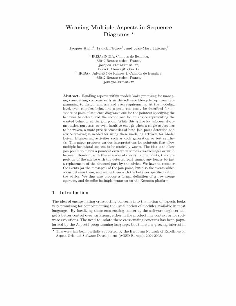
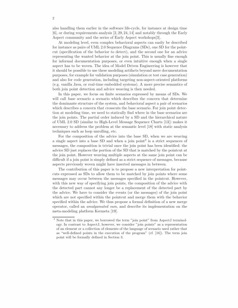
More specifically, bSDs describe a finite number of interactions between a setof objects. They are now considered as collections of events instead of orderedcollections of messages in UML 1.x, which introduce concurrency and asynchro-nism increasing their power of expression. Figure 1 shows several bSDs whichdescribe some interactions between the two objects customer and server. Thevertical lines represent lifelines for the given objects. Interactions between ob-jects are shown as arrows called messages like log in and try again. Each messageis defined by two events: message emission and message reception which inducesan ordering between emission and reception. In this paper, we use arrows rep-resented with an open-head that corresponds to asynchronous messages4 in theUML2.0 standard notation. Asynchronous means that the sending of a mes-sage does not occur at the same time as the corresponding reception (but thesending of a message does necessarily precede the corresponding reception). Con-sequently, in Figure 2, the event e3 corresponding to the reception of the firstmessage a and the event e2 corresponding to the sending of the second messagea are not ordered. Events located on the same lifeline are totally ordered fromtop to bottom (excepted in specific parts of the lifeline called coregions).
We recall that in the UML2.0 specification, the semantics of an Interaction(a Sequence Diagram) is a set of traces, i.e., a set of sequences of events. Conse-quently, all events are not totally ordered. For instance, in Figure 2, the bSD M
4 We use asynchronous messages to be more general
4
generates two traces: {< e1, e3, e2, e4 >; < e1, e2, e3, e4 >}. These traces implythat the events e2 and e3 are not ordered. For this reason, we use the notion ofpartial order as used in other languages of scenarios as Message Sequence Chartsto define formally the notion of bSD:
Fig. 1. Examples of bSDs and combined SD
Fig. 2. Example of a bSD
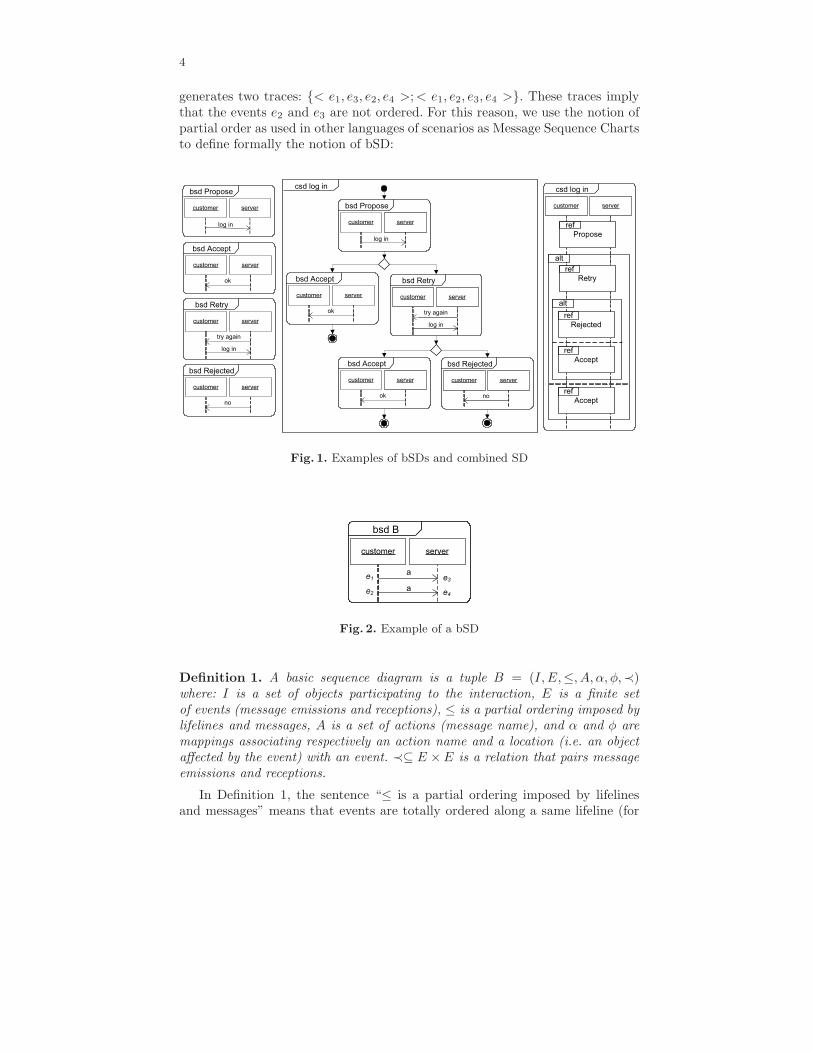
Definition 1. A basic sequence diagram is a tuple B = (I, E,≤, A, α, φ,≺)where: I is a set of objects participating to the interaction, E is a finite setof events (message emissions and receptions), ≤ is a partial ordering imposed bylifelines and messages, A is a set of actions (message name), and α and φ aremappings associating respectively an action name and a location (i.e. an objectaffected by the event) with an event. ≺⊆ E × E is a relation that pairs messageemissions and receptions.
In Definition 1, the sentence “≤ is a partial ordering imposed by lifelinesand messages” means that events are totally ordered along a same lifeline (for
5
instance, in Figure 2 the event e1 precedes the event e2, and the event e3 precedesthe event e4), and a message emission must always precede the correspondingreception (for instance, the event e1 precedes the event e3, and the event e2
precedes the event e4). Then, by transitivity, the partial order ≤ is obtained.Note that the events within an individual lifeline are totally ordered only if eachevent is unique. To ensure the uniqueness of each event, we use a unique identifierfor each event.
We will denote by T (e), the type of an event e. The type of an event indicateswhether an event is a send event or a receive event. We will denote by min(E) ={e ∈ E|∀e′ ∈ E, e′ ≤ e ⇒ e′ = e}, the set of minimal events of E, i.e., the setof events which have no causal predecessor. We will denote by pred≤,E(e) ={e′ ∈ E|e′ ≤ e}, the set of predecessors of the event e, and by succ≤,E(e) ={e′ ∈ E|e ≤ e′}, the set of successor of e. These two notations can be usedwith a subset E′ of the set E: pred≤,E(E′) = {e ∈ E|∃e′ ∈ E′, e ≤ e′} andsucc≤,E(E′) = {e ∈ E|∃e′ ∈ E′, e′ ≤ e}. Slightly misusing the notation, whenM ′ is a bSD which is a “part” of a bSD M , we will denote pred(M ′) as the setof events of M ′ plus the set of predecessors of the events of M ′. Finally, we willalso use, for instance, the notation pred<,E(e) = {e′ ∈ E|e′ < e} to denote theset of strict predecessors of the event e (order < instead of ≤) .
Basic SDs alone do not have sufficient expressive power: they can only definefinite behaviors, without real alternatives. For this reason, they can be composedwith operators such as sequence, alternative and loop to produce a SD calledcombined SDs (cSD) (also called UML 2.0 Interaction Overview Diagram). Fig-ure 1 shows two equivalent views of the same cSD called log in (one view ismore compact). This cSD log in represents the specification of a customer logon a server. If the customer makes two bad attempts, then he/she is rejected.Else, he/she is accepted. We can see that the cSD allows an alternative be-tween the bSDs Accept and Retry, and between the bSDs Accept and Rejected.The cSD also composes sequentially the bSDs Propose and Accept (denotedPropose•Accept), the bSDs Propose and Retry (denoted Propose•Retry), etc...The notion of sequential composition (noted • or seq with the UML2 notation)is central to understanding the semantics of cSD. Note that we use the notionof weak sequential composition presented in the UML 2.0 specification [21](p454). Roughly speaking, (weak) sequential composition of two bSDs consists ofgluing both diagrams along their common lifelines. Note that the sequence op-erator only imposes precedence on events located on the same lifeline, but thatevents located on different lifelines in two bSDs M1 and M2 can be concurrentin M1 • M2. Sequential composition can be formally defined as follows:
6
Definition 2 (Sequential Composition). 5
The sequential composition of two bSDs M1 = (I1, E1,≤1, A1, α1, φ1,≺1) andM2 = (I2, E2,≤2, A2, α2, φ2,≺2) is the bSD M1 • M2 = (I1 ∪ I2, E1 ] E2,≤1•2
, A1 ∪ A2, α1 ∪ α2, φ1 ∪ φ2,≺1 ] ≺2), where: ≤1•2=(
≤1 ] ≤2 ]{(e1, e2) ∈
E1 × E2 | φ1(e1) = φ2(e2)})∗
To calculate the new partial ordering ≤1•2, sequential composition consists inordering events e1 in bMSC M1 and e2 in bMSC M2 if they are situated on thesame lifeline, and then compute the transitive closure of this ordering. In thisdefinition, ] is the disjoint union of two multisets, i.e. an usual union operationwhere common elements of both sets are duplicated. This operator is necessarybecause even if the two operands have two identical events (events with the samename), the two events have to present in the result. Indeed, for instance imaginewe want to make the sequential composition B • B, where B is a bSD whichcontains only one message A. In this case, it is obvious that the two operandscontain the same events, but in the result we want that all the events appear.Thus, in the sequential composition we have to copy and rename the identicalevents and it is made with the disjoint union.
The cSD log in can be considered as a generator of a set of behaviors. For in-stance, the cSD log in generates the set of behaviors {Propose•Accept, Propose•Retry • Accept, Propose • Retry • Rejected}. This set of behaviors can be po-tentially infinite (as soon as a combined SD contains the operator loop, the setof bSDs generated is infinite), but in this paper we will only consider finite SDs.
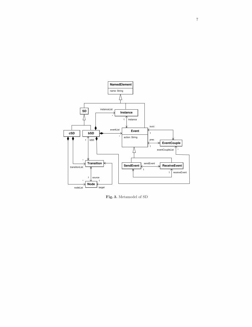
Figure 3 depicts the sequence diagram metamodel used to implement theweaving process presented in this paper (the implementation is described inSection 6). We present this metamodel in this section to show that it fits verywell with the previous definitions of bSD and cSD. In Figure 3, we can note thatcSD has an automata structure, in that a cSD contains a set of nodes and aset of transitions which are linked to bSDs. In this way, cSD can compose bSDsthrough sequences, alternatives and loops. We can also note that a bSD containsa set of objects (class Instance), a set of events (class Event) and a partialorder on the events. The partial order is built with the class EventCouple whichorders two events: the event “prec” precedes the event “succ”. A set of pairs ofevents (prec, succ) forms the partial order. The class Event is linked to the classInstance. In this way, we obtain the mapping φ of Definition 1. Finally, the classEvent contains an attribute “action” which represents the message name (withthis attribute, we easily obtain the mapping α of Definition 1).
2.2 Behavioral Aspects
We define a behavioral aspect as a pair A = (P, Ad) of bSDs. P is a pointcut,i.e. a bSD interpreted as a predicate over the semantics of a base model satisfied
5 We recall that we use the notion of weak sequential composition. It also exists astrong sequential composition. In a strong sequential composition of two bSDs M1
and M2, all the events of M1 have to occur before an event of M2 can occur.
7
Fig. 3. Metamodel of SD
8
by all join points. Ad is an advice, i.e. the new behavior that should replace thebase behavior when it is matched by P . Similarly to AspectJ, where an aspectcan be inserted ’around’, ’before’ or ’after’ a join point, we will show in the nextsections that an advice may equally complete the matched behavior, replace itwith a new behavior, or remove it entirely.
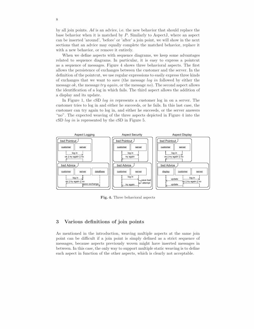
When we define aspects with sequence diagrams, we keep some advantagesrelated to sequence diagrams. In particular, it is easy to express a pointcutas a sequence of messages. Figure 4 shows three behavioral aspects. The firstallows the persistence of exchanges between the customer and the server. In thedefinition of the pointcut, we use regular expressions to easily express three kindsof exchanges that we want to save (the message log in followed by either themessage ok, the message try again, or the message no). The second aspect allowsthe identification of a log in which fails. The third aspect allows the addition ofa display and its update.
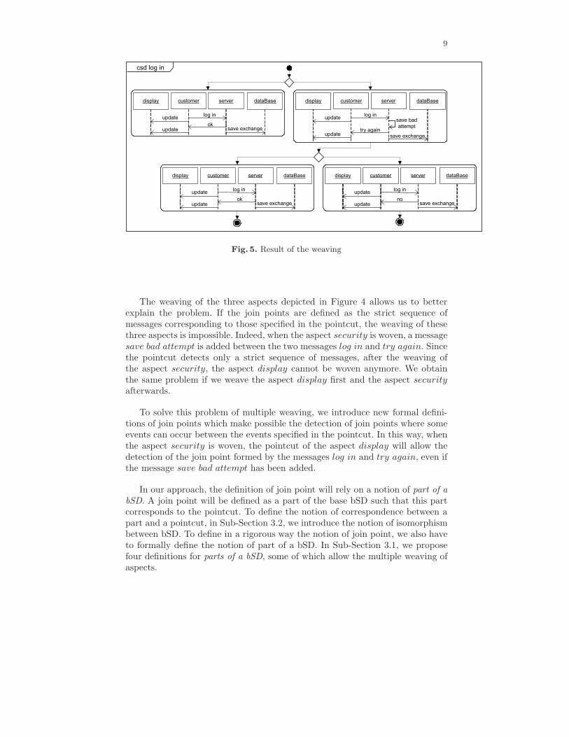
In Figure 1, the cSD log in represents a customer log in on a server. Thecustomer tries to log in and either he succeeds, or he fails. In this last case, thecustomer can try again to log in, and either he succeeds, or the server answers“no”. The expected weaving of the three aspects depicted in Figure 4 into thecSD log in is represented by the cSD in Figure 5.
Fig. 4. Three behavioral aspects
3 Various definitions of join points
As mentioned in the introduction, weaving multiple aspects at the same joinpoint can be difficult if a join point is simply defined as a strict sequence ofmessages, because aspects previously woven might have inserted messages inbetween. In this case, the only way to support multiple static weaving is to defineeach aspect in function of the other aspects, which is clearly not acceptable.
9
Fig. 5. Result of the weaving
The weaving of the three aspects depicted in Figure 4 allows us to betterexplain the problem. If the join points are defined as the strict sequence ofmessages corresponding to those specified in the pointcut, the weaving of thesethree aspects is impossible. Indeed, when the aspect security is woven, a messagesave bad attempt is added between the two messages log in and try again. Sincethe pointcut detects only a strict sequence of messages, after the weaving ofthe aspect security, the aspect display cannot be woven anymore. We obtainthe same problem if we weave the aspect display first and the aspect securityafterwards.
To solve this problem of multiple weaving, we introduce new formal defini-tions of join points which make possible the detection of join points where someevents can occur between the events specified in the pointcut. In this way, whenthe aspect security is woven, the pointcut of the aspect display will allow thedetection of the join point formed by the messages log in and try again, even ifthe message save bad attempt has been added.
In our approach, the definition of join point will rely on a notion of part of abSD. A join point will be defined as a part of the base bSD such that this partcorresponds to the pointcut. To define the notion of correspondence between apart and a pointcut, in Sub-Section 3.2, we introduce the notion of isomorphismbetween bSD. To define in a rigorous way the notion of join point, we also haveto formally define the notion of part of a bSD. In Sub-Section 3.1, we proposefour definitions for parts of a bSD, some of which allow the multiple weaving ofaspects.
10
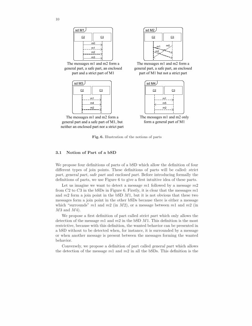
Fig. 6. Illustration of the notions of parts
3.1 Notion of Part of a bSD
We propose four definitions of parts of a bSD which allow the definition of fourdifferent types of join points. These definitions of parts will be called: strict
part, general part, safe part and enclosed part. Before introducing formally thedefinitions of parts, we use Figure 6 to give a first intuitive idea of these parts.
Let us imagine we want to detect a message m1 followed by a message m2from C2 to C3 in the bSDs in Figure 6. Firstly, it is clear that the messages m1and m2 form a join point in the bSD M1, but it is not obvious that these twomessages form a join point in the other bSDs because there is either a messagewhich “surrounds” m1 and m2 (in M2), or a message between m1 and m2 (inM3 and M4).
We propose a first definition of part called strict part which only allows thedetection of the message m1 and m2 in the bSD M1. This definition is the mostrestrictive, because with this definition, the wanted behavior can be presented ina bSD without to be detected when, for instance, it is surrounded by a messageor when another message is present between the messages forming the wantedbehavior.
Conversely, we propose a definition of part called general part which allowsthe detection of the message m1 and m2 in all the bSDs. This definition is the

11
less restrictive. Some messages can be present between the messages forming thewanted behavior.
We also propose one variant of strict part called enclosed part, and onevariant of general part called safe part. An enclosed part allows the detection ofthe message m1 and m2 in the bSDs M1 and M2. As a strict part, an enclosedpart allows the detection of a strict sequence of messages, but in addition, thesequence of messages can be surrounded by others messages as in the bSD M2.A safe part allows the detection of the message m1 and m2 in the bSDs M1, M2and M3, i.e., a safe part allows the detection of a sequence of messages which isnot necessarily a strict sequence of message, but unlike general part, the orderon the events specified in a pointcut have to be preserved in a safe part (thislast remark will be detailed afterwards).
Now, we formally introduce the four definition of parts. A strict part char-acterizing a strict sequence of messages can be defined by:
Definition 3 (Strict Part). Let M be a bSD. We will say that M ′ is a strictpart of M if there exist two bSDs X and Y such that M = X • M ′ • Y , • beingthe operator of sequential composition6.
In Figure 6, the messages m1 and m2 form a strict part only into the bSDM1.
A general part, characterizing a part which can be “surrounded” by messagesand where some messages can occur between the messages of the part, can bedefined by:
Definition 4 (General Part). Let M = (I, E,≤, A, α, φ,≺) be a bSD. We willsay that M ′ = (I ′, E′,≤′, A′, α′, φ′,≺′) is a general part of M if:
– I ′ ⊆ I, E′ ⊆ E, A′ ⊆ A, α′ = α|E′ , φ′ = φ|E′ ;– ≤′⊆≤|E′, ≺′=≺|E′, ∀(e, f) ∈≺, e ∈ E′ ⇔ f ∈ E′.
In Figure 6, the messages m1 and m2 form a general part into all the bSDs.A safe part allows the characterization of a join point where some events can
occur between the events specified in the pointcut, if and only if the order of theevents specified in the pointcut is preserved in the join points. A safe part canbe formally defined by:
Definition 5 (Safe Part). Let M = (I, E,≤, A, α, φ,≺) be a bSD. We will saythat M ′ = (I ′, E′,≤′, A′, α′, φ′,≺′) is a safe part of M if:
– M ′ is a general part of M ;– ≤′=≤|E′.
In Figure 6, the messages m1 and m2 form a safe part into the bSDs M1,M2 and M3. The order of the events of a safe part is the same as the order ofthe events of the initial bSD restricted to the events of the safe part (≤′=≤|E′).
6 Note that according to Definition 2, the sequential composition of two bSDs providesa bSD
12
That is why the messages m1 and m2 do not form a safe part into M4, becausewith only the messages m1 and m2, the receiving of the message m1 and thesending of the message m2 are not ordered whereas in the bSD M4, these twoevents are ordered (by transitivity) because of the message m5.
Finally, an enclosed part defines a strict sequence of messages but this se-quence can be “surrounded” by others messages. More formally:
Definition 6 (Enclosed Part). Let M = (I, E,≤, A, α, φ,≺) be a bSD. Wewill say that M ′ = (I ′, E′,≤′, A′, α′, φ′,≺′) is an enclosed part of M if:
– M ′ is a safe part of M ;– pred≤,E(E′) ∩ succ≤,E(E′) = E′.
In Figure 6, the messages m1 and m2 form an enclosed part into the bSDs M1and M2. Since an enclosed part is a part where no event can be present betweenthe events forming the enclosed part, the message m1 and m2 do not form anenclosed part into M3.
The set pred≤,E(E′) ∩ succ≤,E(E′), which represents the intersection be-tween the set of predecessors of E′ and the set of successors of E′ 7, indi-cates the presence of events “between” the events of E′. Indeed, if an evente /∈ E′ come between two events e′ and e′′ of M ′ (e′ ≤ e ≤ e′′ and φ(e′) =φ(e) = φ(e′′)), then e belongs to pred≤,E(E′) and to succ≤,E(E′). Thereforepred≤,EE′ ∩ succ≤,E(E′) 6= E′
Let us note that for the four proposed definitions of part of a bSD, thedefinitions are based on the semantics of the language of scenarios used, sincewe take account of the message names, but also of the partial order induced bythe pointcut.
3.2 Join Point
Roughly speaking, a join point is defined as a part of the base bSD such that thispart corresponds to the pointcut. Since we have defined four notions for parts ofa bSD, we have four corresponding strategies for detecting join points. It remainsto define the notion of correspondence between the pointcut and the part. To doso, we introduce the notions of morphisms and isomorphisms between bSDs.
Definition 7 (bSD Morphism). Let M = (I, E,≤, A, α, φ,≺) and M ′ =(I ′, E′,≤′, A′, α′, φ′,≺′) be two bSDs. A bSD morphism from M to M ′ is a tripleµ =< µ0, µ1, µ2 > of morphisms, where µ0 : I → I ′, µ1 : E → E′, µ2 : A → A′
and:
(i) ∀(e, f) ∈ E2, e ≤ f ⇒ µ1(e) ≤′ µ1(f) (iii) µ0 ◦ φ = φ′ ◦ µ1
(ii) ∀(e, f) ∈ E2, e ≺ f ⇒ µ1(e) ≺′ µ1(f) (iv) µ2 ◦ α = α′ ◦ µ1
7 Let us note that E′ is necessarily inclued in pred≤,E(E′) and in succ≤,E(E′) becauseeach event of E′ is its own predecessor and its own successor (e ≤ e, ≤ being reflexiveby definition)
13
Fig. 7. Illustration of the notion morphism
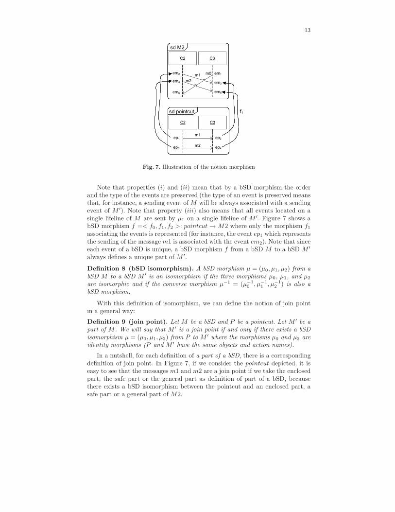
Note that properties (i) and (ii) mean that by a bSD morphism the orderand the type of the events are preserved (the type of an event is preserved meansthat, for instance, a sending event of M will be always associated with a sendingevent of M ′). Note that property (iii) also means that all events located on asingle lifeline of M are sent by µ1 on a single lifeline of M ′. Figure 7 shows abSD morphism f =< f0, f1, f2 >: pointcut → M2 where only the morphism f1
associating the events is represented (for instance, the event ep1 which representsthe sending of the message m1 is associated with the event em2). Note that sinceeach event of a bSD is unique, a bSD morphism f from a bSD M to a bSD M ′
always defines a unique part of M ′.
Definition 8 (bSD isomorphism). A bSD morphism µ = (µ0, µ1, µ2) from abSD M to a bSD M ′ is an isomorphism if the three morphisms µ0, µ1, and µ2
are isomorphic and if the converse morphism µ−1 = (µ−10 , µ−1
1 , µ−12 ) is also a
bSD morphism.
With this definition of isomorphism, we can define the notion of join pointin a general way:
Definition 9 (join point). Let M be a bSD and P be a pointcut. Let M ′ be apart of M . We will say that M ′ is a join point if and only if there exists a bSDisomorphism µ = (µ0, µ1, µ2) from P to M ′ where the morphisms µ0 and µ2 areidentity morphisms (P and M ′ have the same objects and action names).
In a nutshell, for each definition of a part of a bSD, there is a correspondingdefinition of join point. In Figure 7, if we consider the pointcut depicted, it iseasy to see that the messages m1 and m2 are a join point if we take the enclosedpart, the safe part or the general part as definition of part of a bSD, becausethere exists a bSD isomorphism between the pointcut and an enclosed part, asafe part or a general part of M2.
14
3.3 Successive join points
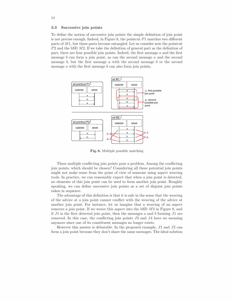
To define the notion of successive join points the simple definition of join pointis not precise enough. Indeed, in Figure 8, the pointcut P1 matches two differentparts of M1, but these parts become entangled. Let us consider now the pointcutP2 and the bSD M2. If we take the definition of general part as the definition ofpart, there are four possible join points. Indeed, the first message a and the firstmessage b can form a join point, as can the second message a and the secondmessage b, but the first message a with the second message b or the secondmessage a with the first message b can also form join points.
Fig. 8. Multiple possible matching
These multiple conflicting join points pose a problem. Among the conflictingjoin points, which should be chosen? Considering all these potential join pointsmight not make sense from the point of view of someone using aspect weavingtools. In practice, we can reasonably expect that when a join point is detected,no elements of this join point can be used to form another join point. Roughlyspeaking, we can define successive join points as a set of disjoint join pointstaken in sequence.
The advantage of this definition is that it is safe in the sense that the weavingof the advice at a join point cannot conflict with the weaving of the advice atanother join point. For instance, let us imagine that a weaving of an aspectremoves a join point. If we weave this aspect into the bSD M2 in Figure 8, andif J1 is the first detected join point, then the messages a and b forming J1 areremoved. In this case, the conflicting join points J3 and J4 have no meaninganymore since one of its constituent messages no longer exists.
However this answer is debatable. In the proposed example, J1 and J2 canform a join point because they don’t share the same messages. The ideal solution
15
is perhaps to give the choice to the user by proposing several semantics of notionof successive join points. Nevertheless, in the sequel of this paper, we will onlygive a definition of the notion of successive join points which is (in an informalway) a sequence of disjoint join points. Other semantics of successive join pointscould be considered as interesting future work.
To define this sequence of disjoint join points, firstly we propose a way toorder the parts of a bSD which are isomorphic to a pointcut in order to findthe first join point matched by the pointcut. Then we show the first join pointis always unique, because the order defined on the parts is a lattice. Secondly,we define successive join points in an inductive way by considering the first joinpoint J which appears in a bSD M , and by continuing with M minus J .
Definition 10 (ordered parts). Let M = (IM , EM ,≤M , AM , αM , φM ,≺M )be a bSD and P = (IP , EP ,≤P , AP , αP , φP ,≺P ) be a pointcut. Let J1 and J2 betwo parts of M such that there exist two bSD isomorphisms f =< f0, f1, f2 >:P → J1 and g =< g0, g1, g2 >: P → J2 . We will say that J1 precedes J2 (orthat J2 succeeds J1), denoted J1 � J2,if and only if:
∀e ∈ EP such that T (e) = send, f1(e) ≤M g1(e).
In Figure 8, with this order we can say that the part J1 precedes J2 in bSDM1. We can also say that the part formed by the first message a and the firstmessage b in the bSD M2 precedes all the other parts formed by a message aand a message b.
Afterwards, we will be especially interested in the minimum part of theorder �, that is to say the part which precedes all the other parts. For a setJP,M of all the parts of a bSD M isomorphic to a pointcut P , we will denote bymin(JP,M ) the minimum part. In the same way, if JP,M is the set of all the joinpoints of P in M , we will call the minimum join point the join point equal tomin(JP,M ). However, � doesn’t define a total order. For instance, in Figure 8,J3 and J4 are not ordered by �. Therefore, it is not obvious that min(JP,M )is unique. To demonstrate the uniqueness of min(JP,M ), we show that � is alattice.
Theorem 1. Let JP,M be the set of join points of a bSD M corresponding to apointcut P and let � be the order on these join points as defined by Definition 10,then (JP,M ,�) is a lattice.
The proof of this theorem is given in Appendix.Now, we can inductively define successive join points as follows:
Definition 11 (Successive Join Points). Let M be a bSD and P be a point-cut. Let J1, J2, . . . Jk be k parts of M isomorphic to P . These k parts are suc-cessive join points of P in M if:
1. J1 is the minimum join point of P in M ;2. ∀i ∈ {2 . . . k}, Ji is the minimum join point of P in M ′, M ′ being the bSD
which contains the events of M minus the events of Ji−1 and all the eventswhich precede the events of Ji−1, so M ′ = M − pred(Ji−1).
16
Taking the minimum join point every time guarantees the uniqueness of thesuccessive join points. Roughly speaking, successive join points are detected insequence at the earliest position where they appear in a bSD.
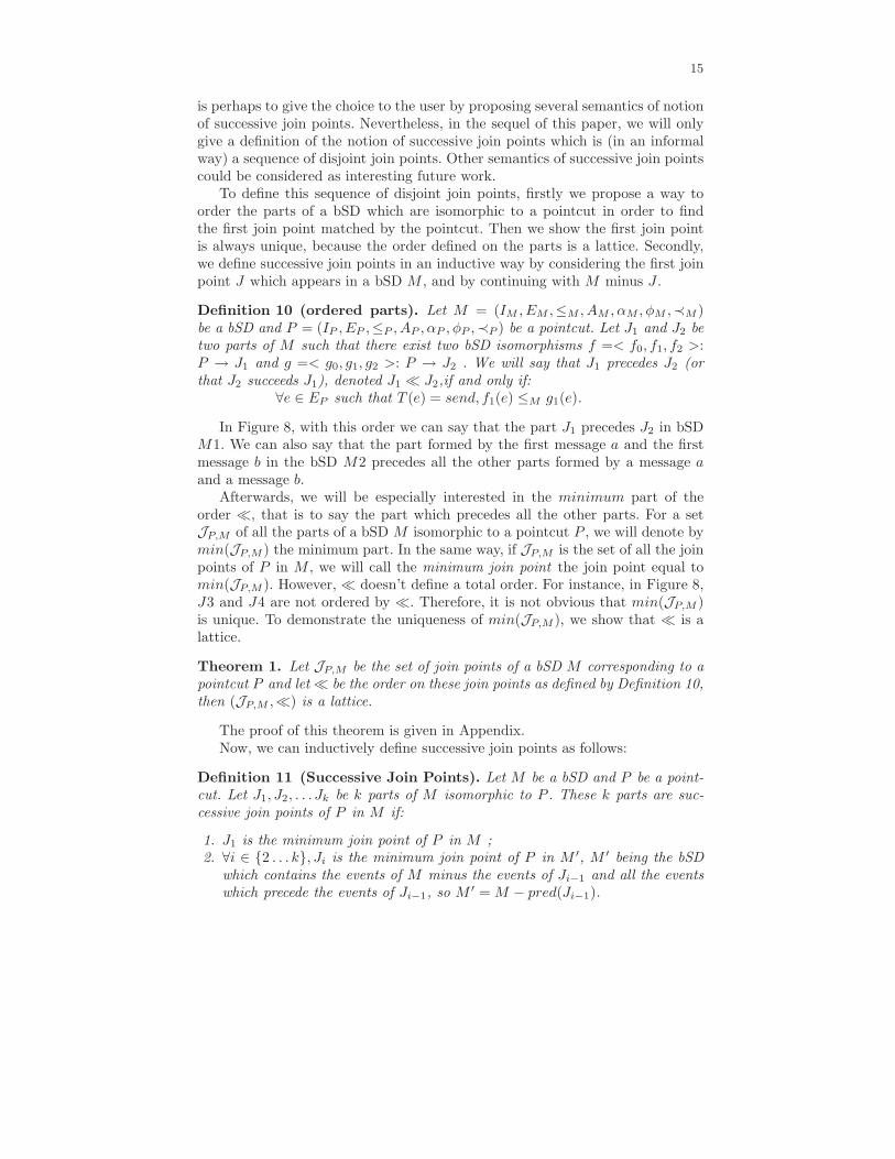
However the result M ′ = M − pred(Ji−1) is not always a well-formed bSD.Indeed, in Figure 9, the minimum join point J1 of P in M is formed by the twofirst messages a and b. When we remove the events pred(J1) (the events of J1
and the events which precede J1), we have to remove the event corresponding tothe sending of the message c. Therefore, the result M ′ = M − pred(J1) is onlyformed by the two last messages a and b, and the event corresponding to thereception of the message c. This is not really a problem because the algorithmsproposed afterwards can be applied even if a bSD is of the kind of M ′.
Fig. 9. Example of a not well-formed bSD
3.4 Which detection stategies should be chosen?
Each definition of part of a bSD presented in the previous sub-section leads to aspecific join point detection strategy. This sub-section discusses some argumentsfor and against these strategies.
First, it is important to note that for the four proposed definitions of partof a bSD (so the four strategies), the definitions are based on the semantics ofthe language of scenarios used, since we take account of the message names, butalso of the partial order induced by the pointcut.
The definition of strict part is the most restrictive, because with this defi-nition, the wanted behavior can be presented in a bSD without being detectedwhen, for instance, it is surrounded by a message. On the other hand, this def-inition is easy: we only search a decomposition of a base bSD M such thatM = M1 •J •M2 (J being the join point). In [18], we have showed that this sim-plicity allows the achieving of good decidability results for join point detectionin infinite scenarios.
Conversely, the definition of general part is the least restrictive. Some mes-sages can be present between the messages forming the wanted behavior. Thisfact can imply the detection of join points interleaved with behaviors not ex-pected by the user. Moreover, the partial order defined by the pointcut is notnecessarily preserved in the detected join point. The major advantage of a joinpoint defined as a general part remains the property to easily weave severalaspects at the same join point.

17
The definitions of enclosed part and safe part combine the advantages andthe drawbacks of a strict part and a general part. An enclosed part looks like astrict part, but it can be surrounded by some messages. Therefore, if we wantto look for a strict sequence of messages in a certain way, this definition seemsto be appropriate. However, an enclosed part has the drawback that it does nottolerate the weaving of multiple aspects at the same join point. If we want toweave several aspects at the same join point, while the partial order definedby the pointcut is preserved, the definition of safe part seems to be appropriate.However, a safe part has the drawback for the detection of join points interleavedwith behaviors not expected by the user, because some messages can be presentbetween the messages of the join points.
Despite this short discussion on the advantage and the drawbacks of eachdefinition, the main interest of the proposed approach is that a user can chooseas he/she wishes the semantics of the weaving in finite scenarios. The user is freeto choose the definition of part which suits him/her the better by adapting thealgorithm of detection according to the chosen definition. We will show how thisflexibility can be easily implemented with the Kermeta environment in Section6.
4 Join point detection
In [18], Klein et al. propose an algorithm to detect a strict part, i.e. a strictsequence of messages. In this paper we propose three new algorithms to detectjoin points defined as an enclosed part, a general part, or a safe part of a bSD.
Firstly, in Sub-Section 4.1, we introduce a general algorithm which containstwo “abstract functions” findSetsOfEvent and min. Secondly, in Sub-Section 4.2,we show how these functions can be specialized for each notion of join points toobtain the three new algorithms.
4.1 General Algorithm
Algorithm 1 allows the construction of an isomorphism µ = (µ0, µ1, µ2) from apointcut P to a part M ′ of a bSD M , such that µ0 and µ2 are identity morphisms.In this way, the isomorphism indicates the first join point M ′ in M . We denoteby πi(M) ⊆ EM the projection of a bSD M on an object i of M and by πE(M)the restriction of a bSD M to a subset E ⊆ EM . Moreover, we use a functionβE which, for an event e of E, gives the position of e on the object containing e.More specifically, the position of an event on an object is defined by the numberof events which precede it on this object: ∀e ∈ E, βE(e) = card({e′ ∈ E|φ(e) =φ(e′) ∧ e′ ≤ e}). Finally, we introduce the function ΓE,o(n) which gives theevent of E localized on the nth position on the object o (ΓE,o(n) = e such thatβE(e) = n ∧ φ(e) = o).
For all objects of a pointcut P , the first part of the algorithm (line 1 to 4)allows the construction of the sets of events of M localized on the same object,such that the actions related to these events are the same as the actions relatedto the events of P . The variable wi represents a word of all events on an objecti of the base bSD M . With the function findSetsOfEvent, we take, for each

18
object i, all the set of (strict or non-strict) sequence of events of M which havethe same action names as the events of P on the object i. Since the decision totake a strict sequence of events or a non-strict sequence of events depends on thedefinition of parts, the function findSetsOfEvent has to be detailed for eachdefinition of parts.
The second part of the algorithm (line 5 to 13) allows the construction of apart M ′ of M when it is possible. After the first part of the algorithm, with thefunction min, we take the first (or minimum) set of events forming a part. Sincewe propose four definitions of parts, this function min has to be specified foreach definition of parts. The notion of minimum set of events or minimum partsis the one defined in the previous section (related to the definition of orderedparts, Definition 10).
An example of how the algorithm works in a practical way is given in thefollowing sub-section.
Note that to detect successive join points in a base bSD M , we start toapply Algorithm 1 on M to obtain the first join point, which we denote J1
(more precisely, we obtain an isomorphism µ = (µ0, µ1, µ2) which defines J1).Secondly, we apply Algorithm 1 on M ′ = M − pred(J1) to obtain the secondjoin point J2, and then we continue in this way as long as the last join pointobtained is not null.
Algorithm 1 Abstract Algorithm of Join Point Detection (P,M)
input:pointcut P = (IP , EP ,≤P , , AP , αP , φP ,≺P ),input: bSD M = (IM , EM ,≤M , AM , αM , φM ,≺M )output:µ = (µ0, µ1, µ2) : P → M ′,M ′ = (IM′ , EM′ ,≤M′ , AM′ , αM′ , φM′ ,≺M′) joinpoint of M
1: For each i ∈ IP do2: aaawi = πi(M) /* a word of all events on the object i */
3: aaaVi = findSetsOfEvent(wi, πi(P ))4: End For5: EM′ = min(∪i∈IP
Vi)6: If (EM′ = ∅) then7: aaareturn(null)8: Else9: aaaµ0 is the identity isomorphism from IP to φM (EM′),
10: aaaµ2 is the identity isomorphism from AP to αM (EM′),11: aaaµ1 is the isomorphism from EP to EM′ such that ∀e ∈ EP ,
aaaµ1(e) = Γvφ(e),φ(e) ◦ βEP(e) aa/* for each object o of Ip, µ1 is built
by associating with the event of o in the ith position, the event
belonging to EM′ on o in the ith position.*/
12: aaareturn(µ = (µ0, µ1, µ2))13: End If
19
4.2 Specialization of the Abstract Algorithm
Enclosed Part Detection
For the detection of enclosed part, the function findSetsOfEvent is equivalentto Vi = {v ∈ E∗
M | ∃u, w, wi = u.v.w ∧ α(v) = α(πi(P ))}. For a word of eventswi on the object i, the function findSetsOfEvent returns a set Vi where eachelement v of Vi is a strict sequence of events which have the same action namesas the events of P on the object i.
With the function min, it remains to check if the order of the events of Pis the same as the order of the events associated to M ′. For that, we check iffor all pairs of sending-reception of events of P , the events of M ′ at the sameposition also form a pair of sending-reception of events. Then, we take the first(or minimum) set of events satisfying the properties. More formally, the functionmin can be rewritten by:
min{v1, . . . , v|IP | ∈ V1 × · · · × V|IP ||
aaaaaaaaaaaaaaaa ∀(e, f) ∈≺P ,(
Γvφ(e),φ(e) ◦ βEP(e), Γvφ(f),φ(f) ◦ βEP
(f))
∈≺M}
Fig. 10. Illustration of the general algorithm using the enclosed part strategy
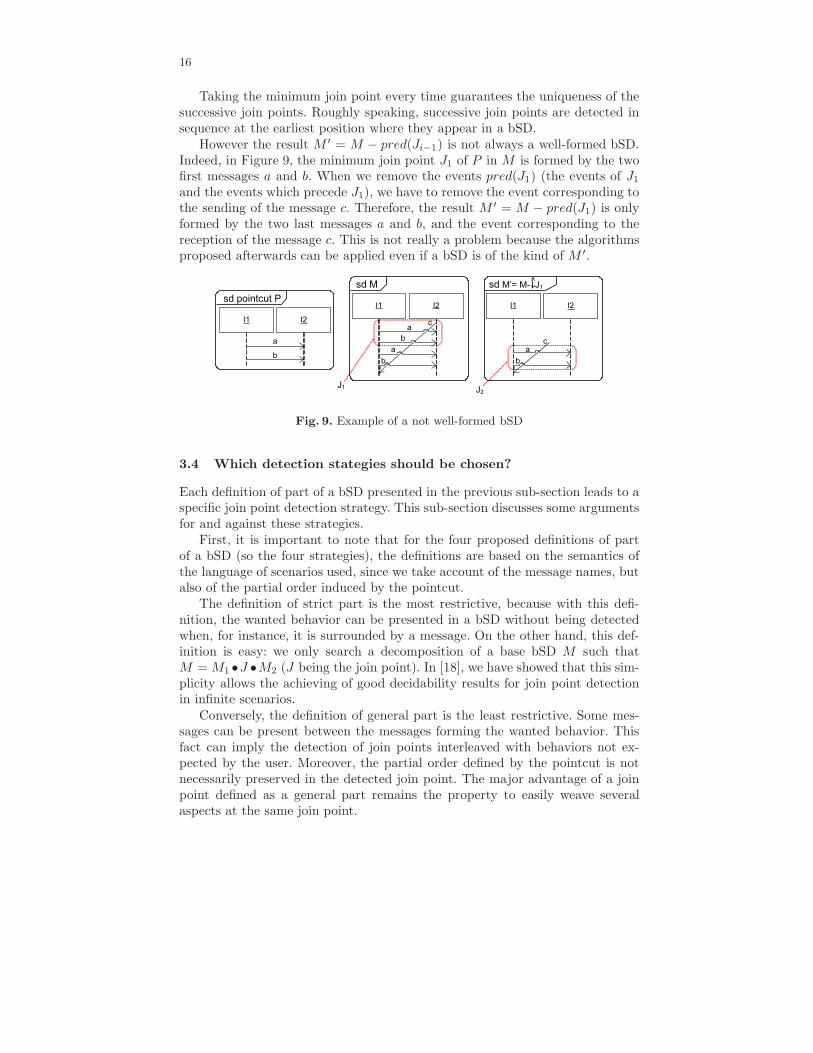
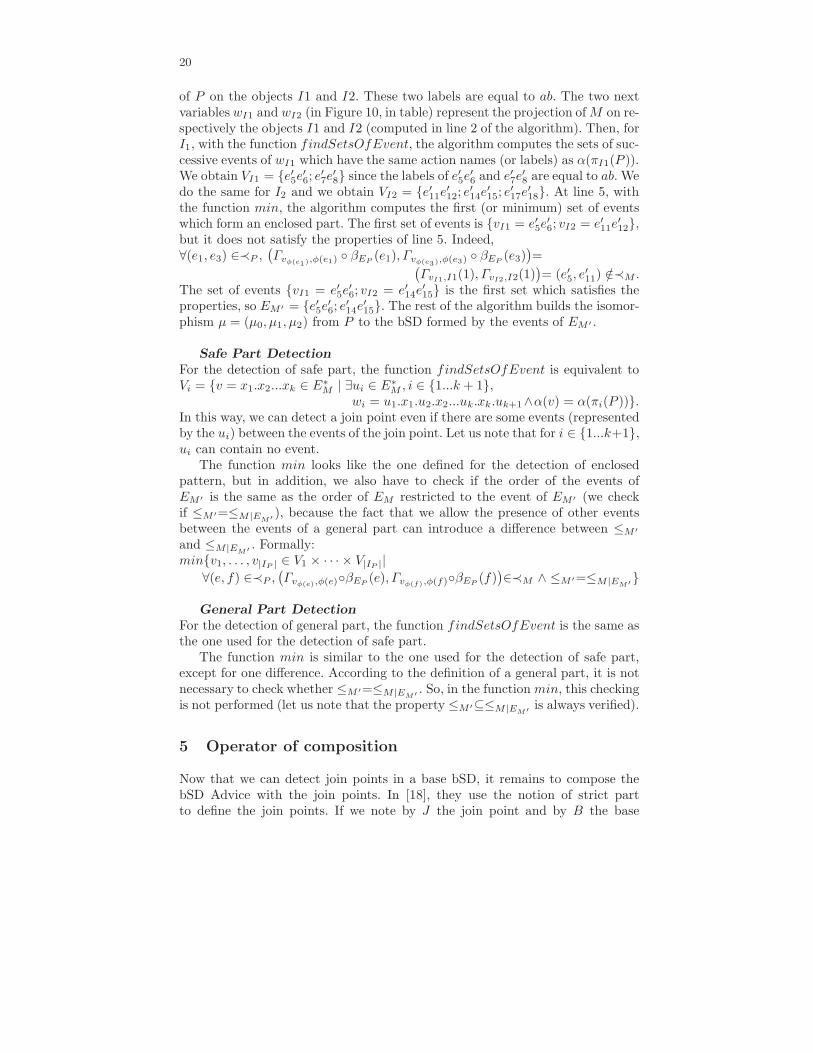
In Figure 10, with the pointcut P and the bSD M , we are going to showhow Algorithm 1 works in a practical way if the function findSetsOfEvent andmin are defined as above. The table in Figure 10 represents the values of somevariables used in the algorithm. The two first variables α(πI1(P )) and α(πI2(P ))(used in line 3 of the algorithm) represent respectively the label of the projection
20
of P on the objects I1 and I2. These two labels are equal to ab. The two nextvariables wI1 and wI2 (in Figure 10, in table) represent the projection of M on re-spectively the objects I1 and I2 (computed in line 2 of the algorithm). Then, forI1, with the function findSetsOfEvent, the algorithm computes the sets of suc-cessive events of wI1 which have the same action names (or labels) as α(πI1(P )).We obtain VI1 = {e′5e
′6; e
′7e
′8} since the labels of e′5e
′6 and e′7e
′8 are equal to ab. We
do the same for I2 and we obtain VI2 = {e′11e′12; e
′14e
′15; e
′17e
′18}. At line 5, with
the function min, the algorithm computes the first (or minimum) set of eventswhich form an enclosed part. The first set of events is {vI1 = e′5e
′6; vI2 = e′11e
′12},
but it does not satisfy the properties of line 5. Indeed,∀(e1, e3) ∈≺P ,
(
Γvφ(e1),φ(e1) ◦ βEP(e1), Γvφ(e3),φ(e3) ◦ βEP
(e3))
=
aaaaaaaaaaaaaaaaaaaaaaaaaaaaaaaaaaa(
ΓvI1,I1(1), ΓvI2,I2(1))
= (e′5, e′11) /∈≺M .
The set of events {vI1 = e′5e′6; vI2 = e′14e
′15} is the first set which satisfies the
properties, so EM ′ = {e′5e′6; e
′14e
′15}. The rest of the algorithm builds the isomor-
phism µ = (µ0, µ1, µ2) from P to the bSD formed by the events of EM ′ .
Safe Part Detection
For the detection of safe part, the function findSetsOfEvent is equivalent toVi = {v = x1.x2...xk ∈ E∗
M | ∃ui ∈ E∗M , i ∈ {1...k + 1},
aaaaaaaaaaaaaaaaaaaaaaaaa wi = u1.x1.u2.x2...uk.xk.uk+1∧α(v) = α(πi(P ))}.In this way, we can detect a join point even if there are some events (representedby the ui) between the events of the join point. Let us note that for i ∈ {1...k+1},ui can contain no event.
The function min looks like the one defined for the detection of enclosedpattern, but in addition, we also have to check if the order of the events ofEM ′ is the same as the order of EM restricted to the event of EM ′ (we checkif ≤M ′=≤M|EM′
), because the fact that we allow the presence of other eventsbetween the events of a general part can introduce a difference between ≤M ′
and ≤M|EM′. Formally:
min{v1, . . . , v|IP | ∈ V1 × · · · × V|IP ||
aaa ∀(e, f) ∈≺P ,(
Γvφ(e),φ(e)◦βEP(e), Γvφ(f),φ(f)◦βEP
(f))
∈≺M ∧ ≤M ′=≤M|EM′}
General Part Detection
For the detection of general part, the function findSetsOfEvent is the same asthe one used for the detection of safe part.
The function min is similar to the one used for the detection of safe part,except for one difference. According to the definition of a general part, it is notnecessary to check whether ≤M ′=≤M|EM′
. So, in the function min, this checkingis not performed (let us note that the property ≤M ′⊆≤M|EM′
is always verified).
5 Operator of composition
Now that we can detect join points in a base bSD, it remains to compose thebSD Advice with the join points. In [18], they use the notion of strict partto define the join points. If we note by J the join point and by B the base
21
bSD, by definition, there exist two bSDs B1 and B2 such that we can writeB = B1 • J •B2 (• being the operator of sequential composition). If we note Adthe advice representing the expected behavior, all you have to do to composethe advice with the join point is to replace the join point by the advice, and thewoven bSD is B = B1 • Ad • B2 .
When we use the notions of general part, safe part or enclosed part to definethe join points, the composition of the advice is not so easy. Indeed, with thesekinds of join points, some messages can surround a join point or some messagescan be present between the messages forming the join point. In these cases, itis not possible to simply replace a join point by an advice because the resultcannot be always expressed with the standard operators of composition such asthe sequential composition operator. Therefore, we have to define a new operatorof composition which takes into account the common parts between a join pointand an advice to produce a new bSD which does not contain copies of similarelements of the two operands. We propose an operator of composition for bSDscalled left amalgamated sum. This sum is inspired by the amalgamated sumproposed in [17]. We add the term left because our operator is not commutative,but it imposes a different role on each operand.
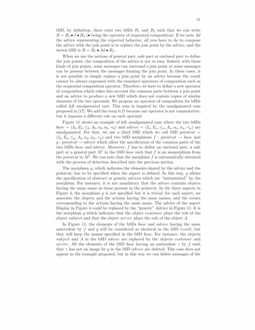
Figure 11 shows an example of left amalgamated sum where the two bSDsbase = (Ib, Eb,≤b, Ab, αb, φb,≺b) and advice = (Ia, Ea,≤a, Aa, αa, φa,≺a) areamalgamated. For that, we use a third bSD which we call bSD pointcut =(Ip, Ep,≤p, Ap, αp, φp,≺p) and two bSD morphisms f : pointcut → base andg : pointcut → advice which allow the specification of the common parts of thetwo bSDs base and advice. Moreover, f has to define an enclosed part, a safepart or a general part M ′ in the bSD base such that f is an isomorphism fromthe pointcut to M ′. We can note that the morphism f is automatically obtainedwith the process of detection described into the previous section.
The morphism g, which indicates the elements shared by the advice and thepointcut, has to be specified when the aspect is defined. In this way, g allowsthe specification of abstract or generic advices which are “instantiated” by themorphism. For instance, it is not mandatory that the advice contains objectshaving the same name as those present in the pointcut. In the three aspects inFigure 4, the morphism g is not specified but it is trivial: for each aspect, weassociate the objects and the actions having the same names, and the eventscorresponding to the actions having the same name. The advice of the aspectDisplay in Figure 4 could be replaced by the “generic” Advice in Figure 11. It isthe morphism g which indicates that the object customer plays the role of theobject subject and that the object server plays the role of the object A.
In Figure 11, the elements of the bSDs base and advice having the sameantecedent by f and g will be considered as identical in the bSD result, butthey will keep the names specified in the bSD base. For instance, the objectssubject and A in the bSD advice are replaced by the objects customer andserver. All the elements of the bSD base having an antecedent γ by f suchthat γ has not an image by g in the bSD advice are deleted. This case does notappear in the example proposed, but in this way we can delete messages of the
22
bSD base. For instance, in an amalgamated sum, if the right operand (the bSDadvice in the example) is an empty bSD then the part of the left operand whichis isomorphic to the pointcut (that is to say the join point), is deleted. Finally,all the elements of the bSDs base and advice having no antecedent by f and gare kept in the bSD result, but the events of the bSD advice will always forma “block” around which the events of the bSD base will be added. For instance,in Figure 11, in the bSD base, if there were an event e on the object customerjust after the message try again, then this event e would be localized just afterthe sending of the message update (event ea7) in the woven SD.
Fig. 11. An example of left amalgamated sum
23
Formally, a left amalgamated sum is defined by:
Definition 12 (left amalgamated sum). Let M0 = (I0, E0,≤0, A0, α0, φ0,≺0
), M1 = (I1, E1,≤1, A1, α1, φ1,≺1) and M2 = (I2, E2,≤2, A2, α2, φ2,≺2) be threebSDs. Let f =< f0, f1, f2 >: M0 → M1 and g =< g0, g1, g2 >: M0 → M2
be two bSDs morphisms such that f(M0) defines a part M ′1 of M1 and that f
is a isomorphism from M0 to M ′1. The left amalgamated sum of M1 and M2
is the bSD M = M1 +f,g M2 where M = (I, E,≤, A, α, φ,≺) is defined by:I = I1 ∪ {i2 ∈ I2|@i0 ∈ I0, g
−10 (i2) = i0};
E = {e1 ∈ E1|∃e0 ∈ E0, ∃e2 ∈ E2, f−11 (e1) = e0 ∧ g1(e0) = e2} ∪ {e1 ∈
E1|@e0 ∈ E0, f−11 (e1) = e0} ∪ {e2 ∈ E2|@e0 ∈ E0, g
−11 (e2) = e0};
≤=
{
(e1, e2) ∈ (E1 ∩ E)2|e1 ≤1 e2
}
∪{
(e1, e2) ∈ (E2 ∩ E)2|e1 ≤2 e2
}
∪{
(e1, e2), e1 ∈ (f1(E0) ∩ E), e2 ∈ (E2 ∩ E)|∃e′2 ∈ E2, e
′2 = g1 ◦ f−1
1 (e1) ∧ e′2 ≤2 e2
}
∪{
(e1, e2), e1 ∈ (E2 ∩ E), e2 ∈ (f1(E0) ∩ E)|∃e′2 ∈ E2, e
′2 = g1 ◦ f−1
1 (e2) ∧ e1 ≤2 e′2}
∪{
(e1, e2), e1 ∈(
pred<1,E1f1(E0) − f1(E0))
, e2 ∈ (E2 ∩ E)|φ(e1) = φ(e2)
}
∪{
(e1, e2), e1 ∈ (E2 ∩ E), e2 ∈(
succ<1,E1f1(E0) − f1(E0))
|φ(e1) = φ(e2)
}
∗
∀e ∈ E, α(e) =
{
α1(e) if e ∈ E1
α2(e) if e ∈ E2;
∀e ∈ E, φ(e) =
{
φ1(e) if e ∈ E1
φ2(e) if e ∈ E2;
A = α(E);≺= (≺1 ∪ ≺2) ∩ E2
The first line of the definition of ≤ means that each pair of events of E1
present in E and ordered by ≤1 remains ordered by ≤. The second line is equiv-alent but for the events of E2. The third line means that an event e1 of E1
present in E precedes an event e2 of E2 present in E, if there exists an evente′2 of E2 preceding e2 and corresponding to e1 in M0. The fourth line meansthat an event e2 of E1 present in E succeeds an event e1 of E2 present in E,if there exists an event e′2 of E2 succeeding e1 and having the same antecedentas e2 in M0. Finally, the fifth line means that an event e1 of E1 preceding thepart detected in M1, will precede all event e2 of E2 if e1 and e2 are localized onthe same object in M . The last line is equivalent but for the events of E1 whichsucceed the detected part.
Let us note that this operator of composition can lead to some situationswhere there are several possibilities to order the events. For instance, in Figure11, let us suppose that the messages update in the bSD advice are sent by theobject A instead of the object customer. Then, when we compose the bSD basewith the bSD advice, the sending of the message update and the message savebad attempt cannot be ordered. In this case, it is the designer who has to specifythe expected order.
24
6 Implementation with Kermeta
To apply the detection and composition algorithms proposed in this paper onpractical examples, we have implemented them within the Kermeta environment.This section is divided in three sub-sections. The first one presents the Kermetaenvironment and details our motivations for using it. The second details how theweaving process is implemented, and the third presents the use of our weaverfrom a user perspective.
6.1 The Kermeta environment
Kermeta [19] is an open source meta-modeling language developed by the Triskellteam at IRISA. It has been designed as an extension to the EMOF 2.0 to be thecore of a meta-modeling platform. Kermeta extends EMOF with an action lan-guage that allows specifying semantics and behaviors of metamodels. The actionlanguage is imperative and object-oriented. It is used to provide an implemen-tation of operations defined in metamodels. As a result the Kermeta languagecan, not only be used for the definition of metamodels but also for implementingtheir semantics, constraints and transformations.
The Kermeta action language has been specially designed to process models.It includes both Object Oriented (OO) features and model specific features.Kermeta includes traditional OO static typing, multiple inheritance and behaviorredefinition/selection with a late binding semantics. To make Kermeta suitablefor model processing, more specific concepts such as opposite properties (i.e.associations) and handling of object containment have been included. In additionto this, convenient constructions of the Object Constraint Language (OCL), suchas closures (e.g. each, collect, select), are also available in Kermeta.
A complete description of the way the language was defined can be foundin [19]. It was successfully used for the implementation of a class diagram com-position technique in [25] but also as a model transformation language in [20].To implement the detection and composition techniques proposed in this paperwe have chosen to use Kermeta for two reasons. First, the language allows im-plementing composition by adding the algorithm in the body of the operationsdefined in the composition metamodel. Second, Kermeta tools are compatiblewith the Eclipse Modeling Framework (EMF) [5] which allows us to use Eclipsetools to edit, store, and visualize models.
6.2 The weaving process as model transformations
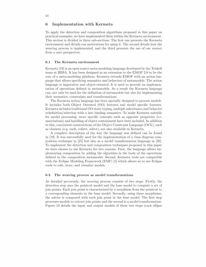
As detailed previously, the weaving process consists of two steps. Firstly, thedetection step uses the pointcut model and the base model to compute a set ofjoin points. Each join point is characterized by a morphism from the pointcut toa corresponding elements in the base model. Secondly, using these morphisms,the advice is composed with each join point in the base model. The first stepprocesses models to extract join points and the second is a model transformation.Figure 12 details the input and output models of these two steps (each ellipse
25
is a model and the black rectangle on the top left-hand corner indicates itsmetamodel). Except for morphisms, all models are SDs.
The first step to process or transform models in Kermeta is the definitionof the input and output metamodels. Thanks to the compatibility of Kermetawith Eclipse tools, we have used Omondo UML [22] which provides a graphicaleditor for metamodels in addition to UML editors. Figure 3 presents the simplemetamodels we are using for SDs. We use this sequence diagram metamodelrather than that of UML2.0 for two major reasons. Firstly, as shown in Section2, the metamodel in Figure 3 fits very well with the formal definitions intro-duced in this paper. So, the metamodel is relatively small, concise and easy tounderstand, and the algorithms presented in this paper are easier to write withthis metamodel rather than with that of UML2.0. Secondly, it is very simple towrite a transformation from the UML2.0 sequence diagram metamodel to themetamodel in Figure 3 because the concepts are very close. So, we can apply theweaving on a model compliant to the UML2.0 metamodel by performing a trans-formation from the UML2.0 sequence diagram metamodel to the metamodel inFigure 3 before the weaving process.
Once the metamodel is defined this way, EMF provides generic tools to cre-ate, edit and save instance models. Kermeta allows, on one hand to complete themetamodel with the specification of the bodies of operation and on the otherhand to process models created with EMF. We used the same process to de-fine a simple metamodel to represent morphisms. This metamodel contains onlyone class called Morphism which encapsulates associations between, instances,messages and events of two SDs.
Fig. 12. Transformation of Models
Using the metamodels for SDs and morphisms, we have designed and imple-mented the complete weaving process. For the detection transformation we havedefined a Kermeta abstract class Detection and three sub-classes to implement
26
the different detection strategies. The composition is implemented in a singleKermeta class.
Both the implementation of detection algorithms and the implementationof the composition operator were used to validate the techniques proposed inthis paper. The composition was implemented first and tested by providing testcases composed of a base scenario, a pointcut scenario, an aspect scenario, andthe morphisms between the pointcut and the advice and between the pointcutand the base scenario. We chose the set of test cases to intuitively cover thestructures of sequence diagrams such as messages between two instances, mes-sages on a single instance, crossing messages or cSD with alternatives, etc. Forall test cases, we checked manually that the composed models correspond to theexpected models. The implementation of the detection algorithms was tested us-ing various simple scenarios corresponding to detection and non-detection cases.We especially had to test the detection algorithms in situations where severalpotential matches could be chosen. In addition to the testing of each step of theweaving, we applied our prototype tool on several small academic examples.
6.3 Using the prototype tool
This goal of this section is to present the use of our weaving technique from auser perspective.
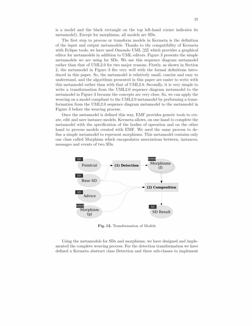
Fig. 13. Screenshot of the base scenario
27
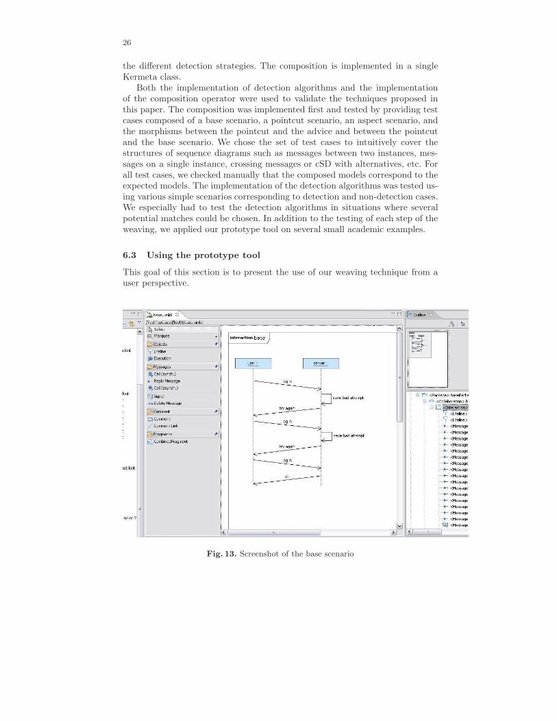
First, the developer has to model the base scenario of his/her application. Todo so we use the UML 2.0 sequence diagram editor available in the TopCaseDeclipse plugin [27]. Figure 13 presents a screenshot of this editor with a basemodel. The base model consists of an interaction between two instances namesuser and server. Figure 14 presents the two scenarios of a behavioral aspect toweave in the base model. The pointcut and advice are presented respectively atthe top and at the bottom of the figure. This goal of this aspect is to update adisplay object whenever a customer object sends a log in message or receives aresponse from the server.
Fig. 14. Screenshot of the aspect scenarios
Once the scenarios for both the base model and the behavioral aspect aredefined, a wizard can be used to perform the weaving. Figure 15 presents ascreenshot of this wizard. To apply our weaving algorithms, the user has toprovide the scenarios corresponding to the pointcut and advice and specify inwhich base models the weaving should be applied. In addition to this, the usercan choose the detection strategy to use. If the strict sequence of messages isselected then the detection strategy corresponds to the notions of strict partand enclosed part of a bSD. The check-box allow surrounding messages allows

28
choosing between these two strategies. It the non-strict sequence of messages isselected, then the notions of safe part and general part of a bSD are used. Thecheck box preserve event order allows choosing between these two strategies.After choosing the detection strategies, the weaving can be performed at onceusing the Weave All button or interactively using the Weave and Skip buttons.
Fig. 15. Screenshot of the weaving wizard
Figure 16 presents the result of the weaving of the behavioral aspect in thebase model of figure 13, with as settings in the wizard, “Non-strict messagesequence” and “Preserve event order” selected.
7 Future Works
The algorithms of join point detection proposed in this paper (when the joinpoints are enclosed parts, safe parts or general parts of a bSD) only work for bSDsor combined SDs which generate a finite number of behaviors (cSDs without loop,in this case the weaving can be applied to each bSDs of the set generated by acSD). When the join points are strict parts of a bSD, the join point detectionwithin infinite behavior is already solved in [18]. More specifically, the detectionof join points within infinite behaviors always terminates when the pointcutis connected, i.e., when the pointcut has no parallel component (the pointcutcannot be written as a parallel composition of two other bSDs). However for the
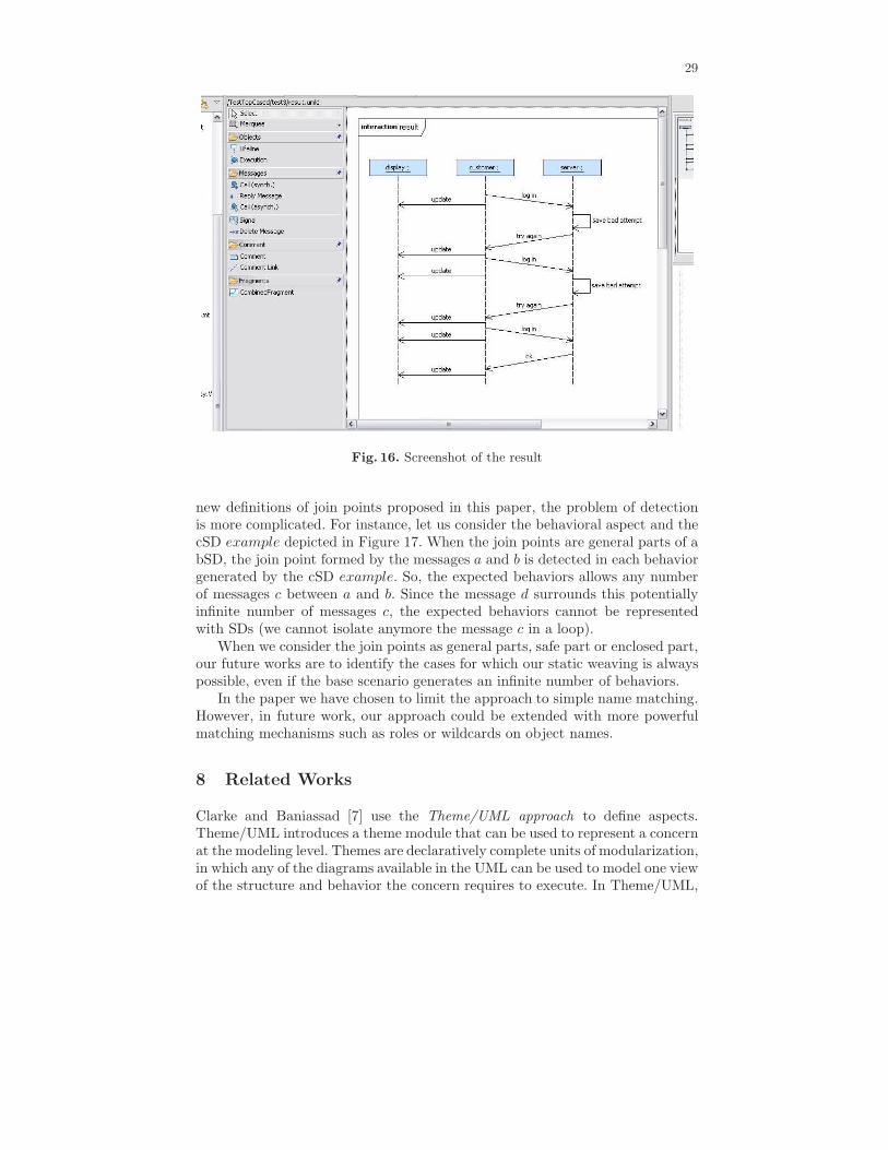
29
Fig. 16. Screenshot of the result
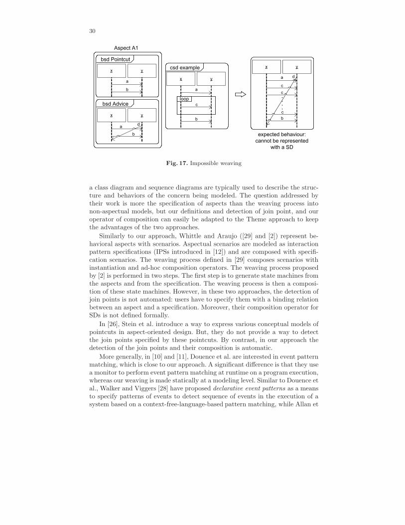
new definitions of join points proposed in this paper, the problem of detectionis more complicated. For instance, let us consider the behavioral aspect and thecSD example depicted in Figure 17. When the join points are general parts of abSD, the join point formed by the messages a and b is detected in each behaviorgenerated by the cSD example. So, the expected behaviors allows any numberof messages c between a and b. Since the message d surrounds this potentiallyinfinite number of messages c, the expected behaviors cannot be representedwith SDs (we cannot isolate anymore the message c in a loop).
When we consider the join points as general parts, safe part or enclosed part,our future works are to identify the cases for which our static weaving is alwayspossible, even if the base scenario generates an infinite number of behaviors.
In the paper we have chosen to limit the approach to simple name matching.However, in future work, our approach could be extended with more powerfulmatching mechanisms such as roles or wildcards on object names.
8 Related Works
Clarke and Baniassad [7] use the Theme/UML approach to define aspects.Theme/UML introduces a theme module that can be used to represent a concernat the modeling level. Themes are declaratively complete units of modularization,in which any of the diagrams available in the UML can be used to model one viewof the structure and behavior the concern requires to execute. In Theme/UML,
30
Fig. 17. Impossible weaving
a class diagram and sequence diagrams are typically used to describe the struc-ture and behaviors of the concern being modeled. The question addressed bytheir work is more the specification of aspects than the weaving process intonon-aspectual models, but our definitions and detection of join point, and ouroperator of composition can easily be adapted to the Theme approach to keepthe advantages of the two approaches.
Similarly to our approach, Whittle and Araujo ([29] and [2]) represent be-havioral aspects with scenarios. Aspectual scenarios are modeled as interactionpattern specifications (IPSs introduced in [12]) and are composed with specifi-cation scenarios. The weaving process defined in [29] composes scenarios withinstantiation and ad-hoc composition operators. The weaving process proposedby [2] is performed in two steps. The first step is to generate state machines fromthe aspects and from the specification. The weaving process is then a composi-tion of these state machines. However, in these two approaches, the detection ofjoin points is not automated: users have to specify them with a binding relationbetween an aspect and a specification. Moreover, their composition operator forSDs is not defined formally.
In [26], Stein et al. introduce a way to express various conceptual models ofpointcuts in aspect-oriented design. But, they do not provide a way to detectthe join points specified by these pointcuts. By contrast, in our approach thedetection of the join points and their composition is automatic.
More generally, in [10] and [11], Douence et al. are interested in event patternmatching, which is close to our approach. A significant difference is that they usea monitor to perform event pattern matching at runtime on a program execution,whereas our weaving is made statically at a modeling level. Similar to Douence etal., Walker and Viggers [28] have proposed declarative event patterns as a meansto specify patterns of events to detect sequence of events in the execution of asystem based on a context-free-language-based pattern matching, while Allan et
31
al. [1] have proposed a new history-based language feature called tracematchesthat enables the programmer to trigger the execution of extra code by specifyinga regular pattern of events in a computation trace. Our approach differs fromboth in that we allow the entire pattern (join point) to be replaced or completed,rather than just the final event in the pattern. We can do that because ourweaving is static. We do not perform the weaving during the execution of thesequence diagram, but we transform a sequence diagram into another sequencediagram where the aspect is woven.
Still at a programming level, recently Bockisch et al. [4] have proposed anovel implementation of the mechanism of cflow present in AspectJ for whichthe efficiency of join point detection for dynamic weaving is improved. However,it is only applicable for the detection of sequence of messages in the controlflow of a method, whereas with our approach, we can detect any interactions.Moreover, since our weaving is static, performance is not a primary issue.
The aspect model and in particular the mechanism to identify join pointsplays a critical role in the applicability of the aspect-oriented methodology. Ac-cording to Kiczales [15], the pointcuts definition language probably has the mostrelevant role in the success of the aspect-oriented technology but most of the so-lutions proposed so far are too tied to the syntax of the programs manipulated.
Ostermann et al. [23] try to address this problem by proposing a static jointpoint model that exploits information from different models of program seman-tics. They show that this model of joint points increases the abstraction leveland the modularity of pointcuts.
9 Conclusion
In this paper we have proposed a technique to statically weave behavioral as-pects into sequence diagrams. Our weaving process is automated, and takes intoaccount the semantics of the model used, i.e., the partial order that a SD induces.
To enable the weaving of multiple aspects, we have proposed a new interpre-tation for pointcuts to allow join points to match them more flexibly. However,with this new way of specifying join points, the composition of the advice withthe detected part could not any longer be a replacement of the detected part bythe advice. We thus had to consider the events (or the messages) of the join pointwhich are not specified within the pointcut and merge them with the behaviorspecified within the advice. We proposed a formal definition for such a mergeoperator, and described its implementation on the Kermeta platform. Moreover,we have presented the use of our weaving technique from a user perspective.
However, our approach suffers from limitations: our algorithms for join pointdetection only work for bSDs or combined SDs which generate a finite numberof behaviors. This has to be considered for further research.
References
1. C. Allan, P. Avgustinov, A. S. Christensen, L. Hendren, S. Kuzins, O. Lhotak,O. de Moor, D. Sereni, G. Sittampalam, and J. Tibble. Adding trace matching

32
with free variables to aspectj. In OOPSLA ’05: Proceedings of the 20th annualACM SIGPLAN conference on Object oriented programming, systems, languages,and applications, volume 40, pages 345–364. ACM Press, 2005.
2. J. Araujo, J. Whittle, and Kim. Modeling and composing scenario-based require-ments with aspects. In Proceedings of RE 2004, Kyoto, Japan, September 2004.
3. E. Aspect, 2006. http://www.early-aspects.net/.4. C. Bockisch, S. Kanthak, M. Haupt, M. Arnold, and M. Mezini. Efficient con-
trol flow quantification. In OOPSLA ’06: Proceedings of the 21th annual ACMSIGPLAN conference on Object oriented programming, systems, languages, andapplications, volume 41, pages 125–138. ACM Press, 2006.
5. F. Budinsky, D. Steinberg, E. Merks, R. Ellersick, and T. Grose. Eclipse ModelingFramework. The Eclipse Series. Addison Wesley Professional, 2003.
6. S. Clarke. Composition of Object-Oriented Software Design Models. PhD thesis,Dublin City University, 2001.
7. S. Clarke and E. Baniassad. Aspect-Oriented Analysis and Design: The ThemeApproach. Number ISBN: 0-321-24674-8. Addison Wesley, 2005.
8. W. Damm and D. Harel. LSCs: Breathing life into message sequence charts. vol-ume 19, pages 45–80, 2001.
9. B. A. Davey and H. A. Priestley. Introduction to Lattices and Order. CambridgeMathematical Textbooks, 1990.
10. R. Douence, P. Fradet, and M. Sudholt. A framework for the detection and reso-lution of aspect interactions. In Proceedings of GPCE’02, LNCS. Springer, 2002.
11. R. Douence, O. Motelet, and M. Sudholt. A formal definition of crosscuts. InReflection’01, pages 170–186, 2001.
12. R. B. France, D.-K. Kim, S. Ghosh, and E. Song. A uml-based pattern specificationtechnique. IEEE TSE, vol.30(3), 193-206, March 2004, 2004.
13. ITU-TS. ITU-TS Recommendation Z.120: Message Sequence Chart (MSC). ITU-TS, Geneva, September 1999.
14. I. Jacobson and P.-W. Ng. Aspect-Oriented Software Development with Use Cases.Addison-Wesley, 2004.
15. G. Kiczales. The fun has just begun. Keynote of AOSD’03, 2003.16. G. Kiczales, E. Hilsdale, J. Hugunin, M. Kersten, J. Palm, and W. G. Griswold.
An overview of AspectJ. Lecture Notes in Computer Science, 2072:327–355, 2001.17. J. Klein, B. Caillaud, and L. Helouet. Merging scenarios. In Workshop on FMICS,
pages 209–226, Linz, Austria, sep 2004.18. J. Klein, L. Helouet, and J.-M. Jezequel. Semantic-based weaving of scenarios. In
AOSD, Bonn, Germany, 2006. ACM.19. P.-A. Muller, F. Fleurey, and J.-M. Jezequel. Weaving executability into object-
oriented meta-languages. In Proc. of MODELS/UML, LNCS, Jamaica, 2005.20. P.-A. Muller, F. Fleurey, D. Vojtisek, Z. Drey, D. Pollet, F. Fondement, P. Studer,
and J.-M. Jezequel. On executable meta-languages applied to model transforma-tions. In Model Transformations In Practice Workshop, Jamaica, 2005.
21. OMG. Uml superstructure, v2.0. OMG Document number formal/05-07-04, 2005.22. Omondo, 2006. http://www.omondo.com.23. K. Ostermann, M. Mezini, and C. Bockisch. Expressive pointcuts for increased
modularity. In Proceedings of ECOOP’05. Springer LNCS, 2005.24. A. Rashid, A. M. D. Moreira, and J. Araujo. Modularisation and composition of
aspectual requirements. In proceedings of AOSD’03, pages 11–20, 2003.25. R. Reddy, R. France, S. Ghosh, F. Fleurey, and B. Baudry. Model composition -
a signature-based approach. In AOM Workshop, Montego Bay, Oct. 2005.

33
26. D. Stein, S. Hanenberg, and R. Unland. Expressing different conceptual models ofjoin point selection in aspect-oriented design. In AOSD, Bonn, Mars 2006.
27. TopCaseD, 2006. http://www.topcased.org/.28. R. J. Walker and K. Viggers. Implementing protocols via declarative event pat-
terns. In ACM Sigsoft International Symposium on Foundations of Software En-gineering (FSE-12), 29(6):159–169, 2004.
29. J. Whittle and J. Araujo. Scenario modelling with aspects. IEE Proceedings -Software, 151(4):157–172, 2004.
Appendix
This appendix contains the proof of Theorem 1.Proof:To demonstrate Theorem 1, we assume that two overtaking messages cannot
have the same name and we use the following lemma which can be found in thebook “Introduction to Lattices and Order” [9](p.110):
Lemma 1. Let (L,∨,∧) be a triple where L is a non-empty set equipped withtwo binary operations ∨ and ∧ which satisfy for all a, b, c ∈ L:
– (1) a ∨ a = a and a ∧ a = a (idempotency laws);– (2) a ∨ b = b ∨ a and a ∧ b = b ∧ a (commutative laws );– (3) (a ∨ b) ∨ c = a ∨ (b ∨ c) et (a ∧ b) ∧ c = a ∧ (b ∧ c) (associative laws);– (4) a ∨ (a ∧ b) = a et a ∧ (a ∨ b) = a (absorption laws).
then:
– (i) ∀a, b ∈ L, a ∨ b = b ⇔ a ∧ b = a;– (ii) If we define ≤ by a ≤ b if a ∨ b = b, then ≤ is an order relation;– (iii) With ≤ as in (ii), (L,≤) is a lattice such that ∀a, b ∈ L, a∨b = sup{a, b}
and a ∧ b = inf{a, b}.
�
We will show that JP,M can be equipped with two binary operations ∨ and∧ which verify the properties 1 to 4 of the lemma.
Let JP,M be the set of join points corresponding to a pointcut P = (IP , EP ,≤P
, AP , αP , φP ,≺P ) in a bSD M = (I, E,≤, A, α, φ,≺). Let ∨ and ∧ be the oper-ators defined for each Ji, Jj of JP,M by:
Ji ∨ Jj = {e, f ∈ Ji|e ≺ f, ∃e′ ∈ EP , e = µi1(e′), µj1 (e
′) ≤ e}∪{e, f ∈ Jj |e ≺ f, ∃e′ ∈ EP , e = µj1(e
′), µi1(e′) ≤ e}
Ji ∧ Jj = {e, f ∈ Ji|e ≺ f, ∃e′ ∈ EP , e = µi1(e′), e ≤ µj1(e
′)}∪{e, f ∈ Jj |e ≺ f, ∃e′ ∈ EP , e = µj1(e
′), e ≤ µi1(e′)}
µi =< µi0 , µi1 , µi2 > and µj =< µj0 , µj1 , µj2 > being the isomorphismsassociating P to the respective join points Ji and Jj .
34
For (JP,M ,∨,∧), the properties (1) and (2) of the lemma are verified (triv-ial). Let Ji, Jj and Jk be three join points and µi =< µi0 , µi1 , µi2 >, µj =<µj0 , µj1 , µj2 > and µk =< µk0 , µk1 , µk2 > the three isomorphisms associatingrespectively P to Ji, Jj and Jk. Let e and f be two events of M such that e ≺ f .If e and f belong to Ji and (Ji ∨ Jj) ∨ Jk, let e′ be the corresponding eventin P such that e = µi1(e
′), then according to the definition of ∨, e succeeds toµj1(e
′) and µk1(e′). Therefore, e and f also belong to Ji ∨ (Jj ∨Jk). In this way,
we easily show that (Ji ∨ Jj) ∨ Jk = Ji ∨ (Jj ∨ Jk). In the same way, we alsoshow that (Ji ∧ Jj) ∧ Jk = Ji ∧ (Jj ∧ Jk). Finally, to prove the property (4),let us consider the two join points Ji and Jj and their associated morphisms µi
and µj . Let e2 and f2 be two events belonging to Jj and Ji ∨ (Ji ∧ Jj) (andconsequently to Ji ∧ Jj) but not to Ji. Let us note e′ the event belonging to Psuch that e2 = µj1(e
′). If e1 = µi1(e′), then since e2 belongs to Ji ∧ Jj , e2 ≤ e1,
and since e2 belongs to Ji∨(Ji∧Jj), e1 ≤ e2. Impossible, therefore all the eventsof Ji ∨ (Ji ∧ Jj) belong to Ji.
According to the lemma, (JP,M ,�′), with �′ defined by Ji �′ Jj if Ji∨Jj =
Jj , is a lattice. Moreover �′ is equivalent to the order � of Definition 10. Theequivalence is easy to demonstrate. Let Ji and Jj be two join points, and µi andµj their associated isomorphisms to P . If Ji �
′ Jj , by definition Ji ∨ Jj = Jj ,and thus all the message send events of Jj succeed those of Ji. The converse istrivial.
�