Embed Size (px)
Citation preview

WEB BASED INVENTORY CONTROL &
ORDER PROCESSING SYSTEM FOR
JC ENTERPRISE
M.P.M.C Fernando
BIT Registration Number: R100674
Index Number: 1006746
Client Name: Chandimal Fernando
Supervisor: M.A.T.C Perera
November 2017
This dissertation is submitted in partial fulfillment of the requirement of the
Degree of Bachelor of Information Technology (external) of the
University of Colombo School of Computing
BIT
ii
DECLARATION

iii
ABSTRACT
JC Enterprise has been distributing all kind of sewing machine & machining parts in various
places in Sri Lanka. Currently JC Enterprise is managing orders, purchasing, and inventory
control do in manual.
The system has adapted Model View Controller (MVC) architecture and Object Oriented
techniques. In addition Unified Modeling Language (UML) is basically used for designing of
the system. Hypertext Pre-Processor (PHP) which is a server-side scripting language was used
to build the system & MySQL was deployed to manage the database of the system.
The proposed system will facilitate such as online customer registration, online order
handling, online supplier handling, and payment, GRN notice handling etc, best support to
business. Accountability can be maintained to proposed system. Only authorized user can log
in to system via login form and can transaction. The system was thoroughly tested in a multi-
stage testing process which included unit testing, integration testing, system testing and
acceptance testing. Overall, system was able to successfully automate machine product
management and end user functionalities as expected resulting positive customer feedback.
At the end of this project would be helpful for JC Enterprise Company in achieving their
goals effectively and efficiently.

iv
ACKNOWLEDGEMENT
First of all I would like to thank the staff of UCSC including the Director, BIT Coordinator
and the academic staff for creating such a great programme as the, students can learn much
and have good exposure to Information Technology.
Secondly, I would like to extend my gratitude to my Project Supervisor Mr. M.A.T.C Perera
always gave me guidance and encouragement me while I was suspicious, and also once again
thank his for giving better subject knowledge and further guidance.
Thirdly, I would like to thank my client, Mr. Chandimal Fernando, for giving me a very
valuable discussion with regarding on this project. They gave all the information I needed to
know about this process, they also worked very closely.
In the end, I am grateful to my lovely friends. My success and the failures of my life were
with me without intervening with me. They share my knowledge and experience with me and
I am happy to have good friends in my life.
v
TABLE OF CONTENT
DECLARATION ............................................................................................................. ii
ABSTRACT .................................................................................................................... iii
ACKNOWLEDGEMENT ............................................................................................. iv
TABLE OF CONTENT .................................................................................................. v
LIST OF FIGURES ........................................................................................................ ix
LIST OF TABLES ......................................................................................................... xi
LIST OF ACRONYMS ................................................................................................. xii
CHAPTER 1 - INTRODUCTION ................................................................................. 1
1.1 Introduction ......................................................................................................................... 1
1.2 Motivation for project ......................................................................................................... 1
1.3 Objectives and scope of Pproposed Pproject ....................................................................... 2
1.4 Scope ................................................................................................................................... 2
1.5 Structure of the Dissertation ................................................................................................ 3
Chapter 2 – Analysis ............................................................................................................. 3
Chapter 3 – Design ................................................................................................................ 3
Chapter 4 – Implementation .................................................................................................. 3
Chapter 5 – Evaluation .......................................................................................................... 3
Chapter 6 – Conclusion ......................................................................................................... 3
CHAPTER 2 – ANALYSIS ............................................................................................ 4
2.1 Introduction ......................................................................................................................... 4
2.2 Fact Finding Techniques ..................................................................................................... 4
2.3 Existing System ................................................................................................................... 5
2.4 Drawbacks of the Existing System ...................................................................................... 6
2.5 Proposed System ................................................................................................................. 6
2.6 Functional Requirements ..................................................................................................... 7
2.6.1 User Management Module ........................................................................................... 7
vi
2.6.2 Report Generate Module .............................................................................................. 7
2.6.3 Invoicing Module ......................................................................................................... 7
2.6.4 Stock Control Module .................................................................................................. 7
2.6.5 Order Module ............................................................................................................... 8
2.7 Non Functional Requirements ............................................................................................. 8
2.8 Existing Similar Systems..................................................................................................... 9
CHAPTER 3 - DESIGN ................................................................................................ 11
3.1 Introduction ....................................................................................................................... 11
3.2 Alternate Solution.............................................................................................................. 11
3.3 Justification of the selected solution.................................................................................. 12
3.4 Design Approach ............................................................................................................... 12
3.5 Object Oriented Design Using the UML ........................................................................... 13
3.5.1 Use Case Diagram for Web Based Inventory Control & Order Processing System .. 14
3.5.2 Class Diagram for Web Based Inventory Control & Order Processing System ........ 15
3.5.3 Sequence Diagram for Web Based Inventory Control & Order Processing System .. 16
3.5.4 ER Diagram for Web Based Inventory Control & Order Processing System ............ 17
3.6 User Interface Design ........................................................................................................ 17
3.6.1 The Home Page .......................................................................................................... 19
3.6.2 Login Interface ........................................................................................................... 20
3.6.3 Administrator Home Page .......................................................................................... 20
3.6.4 Interface for Add, Delete and Update Supplier .......................................................... 21
3.6.5 Data Entry Forms ....................................................................................................... 21
3.6.6 Reports Viewing Interfaces ........................................................................................ 22
3.6.7 Chart Viewing Interface ............................................................................................. 22
CHAPTER 4 - IMPLIMENTATION .......................................................................... 23
4.1 Introduction ....................................................................................................................... 23
4.2 Hardware and Software Requirement ............................................................................... 23
4.2.1 Hardware Requirements ............................................................................................. 23
4.2.2 Software Requirements .............................................................................................. 23
4.3 Support Language and techniques ..................................................................................... 24

vii
4.4 Code and Main Modules of the System ............................................................................ 25
4.4.1 Major Code Segments ................................................................................................ 26
4.4.2 Reused Modules ......................................................................................................... 28
CHAPTER 5 - EVALUATION .................................................................................... 29
5.1 Introduction ....................................................................................................................... 29
5.2 Verification and Validation testing of a System ................................................................ 29
5.3 Test Plan ............................................................................................................................ 29
5.3. 1 Objectives .................................................................................................................. 29
5.3.2 Assumptions ............................................................................................................... 29
5.3.3 Scope .......................................................................................................................... 30
5.3.4 Test Process ................................................................................................................ 30
5.4 Testing Types .................................................................................................................... 31
5.4.1 Unit testing ................................................................................................................. 31
5.4.2 Black Box testing ....................................................................................................... 31
5.4.3 White box testing ........................................................................................................ 31
5.4.4 Integration testing ....................................................................................................... 32
5.4.5 System Testing ........................................................................................................... 32
5.4.6 User acceptance Testing (Beta Testing) ..................................................................... 32
5.5 TEST CASES .................................................................................................................... 32
5.5.1 Purchasing Module (GRN) ......................................................................................... 33
5.5.2 Supplier Registration Module.................................................................................... 33
5.5.3 User Management Module ......................................................................................... 34
5.5.4 Print Report Module ................................................................................................... 34
5.6 ACCEPTANCE TEST ...................................................................................................... 34
5.7 USER EVALUATION ...................................................................................................... 35
CHAPTER 6 - CONCLUTION ................................................................................... 36
6.1 Overview ........................................................................................................................... 36
6.2 Critical Assessment of the Proposed System .................................................................... 36
6.3 Problems Encountered while Developing the System ....................................................... 37
6.4 Lessons learnt .................................................................................................................... 37

viii
6.5 Future Improvements ........................................................................................................ 38
REFERENCES .............................................................................................................. 39
Appendix A – System Documentation ......................................................................... 41
Appendix B – Design Documentation .......................................................................... 46
Appendix C – User Documentation ............................................................................. 54
Appendix D – Management Reports ........................................................................... 61
Appendix E - Test Results ............................................................................................ 64
Appendix F – Code Listing ........................................................................................... 67
Glossary .......................................................................................................................... 84
Index ............................................................................................................................... 85
ix
LIST OF FIGURES
Figure 2.1: Use case Diagram of existing system ................................................................................... 5
Figure 2.2: Use Case Diagram for Proposed System .............................................................................. 6
Figure 2.3: inFlow Inventory Software ................................................................................................... 9
Figure 2.4: Inventory Track Software System ...................................................................................... 10
Figure 3.1: MVC Architecture .............................................................................................................. 13
Figure 3.2: Top level Use Case Diagram of the System ....................................................................... 14
Figure3.3: Class Diagram of the System ............................................................................................... 15
Figure3.4: Sequence Diagram for Login ............................................................................................... 16
Figure 3.5: ER diagrams of the proposed system .................................................................................. 17
Figure 3.6: Home page .......................................................................................................................... 19
Figure 3.7: Login Interface .................................................................................................................... 20
Figure 3.8: Administrator Home Page................................................................................................... 20
figure 3.9: Add new, Delete, Edit Interface ........................................................................................... 21
Figure3.10: Data Entry Form ................................................................................................................ 21
Figure 3.11: Transaction detail report ................................................................................................... 22
Figure3.12: Chart Viewing .................................................................................................................... 22
Figure 4.1: MVC Architecture .............................................................................................................. 25
Figure 5.1: User Evaluation Form ......................................................................................................... 35
Figure 5.2: Employee Feedback ............................................................................................................ 35
Figure B.1: Use Case of User Management .......................................................................................... 46
Figure B.2: Use Case Diagram of the Supplier ..................................................................................... 49
Figure B.3: Use case Diagram of Order Management Module ............................................................. 50
Figure B.4: Activity Diagram for Ordering Model ............................................................................... 52
Figure B.5: Activity diagram for Login ................................................................................................ 53
Figure B.6: Class diagram of the system ............................................................................................... 53
Figure C.1: Login Form......................................................................................................................... 54
Figure C.2: Home Page ......................................................................................................................... 55
Figure C.3: View Items Screen ............................................................................................................. 56
x
Figure C.4: Customer Registration ........................................................................................................ 57
Figure C.5: Current Stock ..................................................................................................................... 57
Figure C.6: Approved Invoices ............................................................................................................. 58
Figure C.7: Purchase Order Form ......................................................................................................... 58
Figure C.8: Goods Receiving Form ...................................................................................................... 59
Figure C.9: Customer Payment Form .................................................................................................... 59
Figure C.10: Pending Invoices .............................................................................................................. 60
Figure C.11: Invoice Form .................................................................................................................... 60
Figure D.1: Transactional Detail Report ............................................................................................... 61
Figure D.2: Customer Details Report .................................................................................................... 61
Figure D.3: Current Stock Level Details Report ................................................................................... 62
Figure D.4: Goods Receiving Details Report ........................................................................................ 62
Figure D.5: Invoice Details Report ....................................................................................................... 63
Figure D.6: Overdue Customer Report ................................................................................................. 63

xi
LIST OF TABLES
Table 5.1: Test Cases for Purchasing Module ....................................................................................... 33
Table 5.2: Test Cases for Supplier Register Module ............................................................................. 33
Table 5.3: Test Cases for User Login .................................................................................................... 34
Table 5.4: Test Cases for Report Module .............................................................................................. 34
Table A.1: Hardware Requirements ...................................................................................................... 41
Table A.2: Software Requirements ....................................................................................................... 41
Table B.1: Use Case Description for Add User .................................................................................... 46
Table B.2: Use Case Description for Edit User ..................................................................................... 47
Table B.3: Use Case Description for Delete User ................................................................................. 48
Table B.4: Use Case Description for Register Supplier ........................................................................ 49
Table B.5: Use Case Description for View Supplier ............................................................................. 50
Table B.6: Use Case Description for Place Order ................................................................................. 51
Table B.7: Use Case Description for View Order ................................................................................. 51
Table B.8: Use Case Description for Modify Order .............................................................................. 52
Table E.1: Test Data of Login Module .................................................................................................. 64
Table E.2: Test Data of Customer Registration Module ....................................................................... 65
Table E.3: Test Data of add New Item to System ................................................................................. 66

xii
LIST OF ACRONYMS
AJAX - Asynchronous JavaScript Technology and XML
BIT – Bachelor of Information Technology
CSS - Cascading Style Sheet
ERD – Entity Relationship Diagram
GRN` - Goods Receiving Notice
GUI - Graphical User Interface
HTML - Hypertext Mark-up Language
MVC – Model View Controller
MySQL – My Structured Query Language
OOP – Object Oriented Programming
PHP – Hypertext Pre-Processor
UML – Unified Modeling Language
XAMPP – Platform (X), Apache (A), MariaDB (M), PHP (P) and Perl (P)

1
CHAPTER 1 - INTRODUCTION
1.1 Introduction
Information Communication Technology is become part of the life for accessing many
applications at present. First of all, every company nowadays uses a computer to store its data
and make different kinds of operations. A company would have to store millions of papers
and documents. Moreover, a customer would have to wait hours to check his order status or
get a piece of information, request to order and about his transactions.
This proposed system is specially targeted on data transferring mechanism, data processing
and report generation. Therefore, this web-based inventory control & order processing system
this project might be able to help achieve this process by reducing the manual paper work at
JC Enterprise.
1.2 Motivation for project
JC Enterprise is a company that import and distribute sewing machine, machine parts and
their equipments. JC Enterprise currently runs their process manually. It doesn’t support to
achieve their goal successfully.
The following issues have been occurred in their day to day operations.
It is difficult to identify urgent purchasing requirements.
Many difficulties arise when they try to generate reports.
It is difficult to analyze and get a decision on stock status, especially individual stock
status of equipments.
Currently, the company has a highly disorganized accessing procedure to modify
company inventory.
It is also difficult to make better decisions and it is a waste of time and resources. Further, by
developing such a system, new technologies can be tried out that have been learnt throughout
the BIT degree program. It fulfills the requirements to complete the BIT degree program as
well.
2
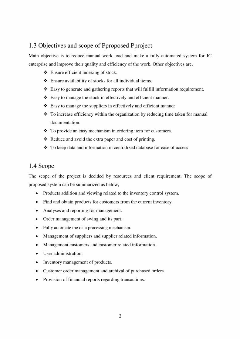
1.3 Objectives and scope of Pproposed Pproject
Main objective is to reduce manual work load and make a fully automated system for JC
enterprise and improve their quality and efficiency of the work. Other objectives are,
Ensure efficient indexing of stock.
Ensure availability of stocks for all individual items.
Easy to generate and gathering reports that will fulfill information requirement.
Easy to manage the stock in effectively and efficient manner.
Easy to manage the suppliers in effectively and efficient manner
To increase efficiency within the organization by reducing time taken for manual
documentation.
To provide an easy mechanism in ordering item for customers.
Reduce and avoid the extra paper and cost of printing.
To keep data and information in centralized database for ease of access
1.4 Scope
The scope of the project is decided by resources and client requirement. The scope of
proposed system can be summarized as below,
Products addition and viewing related to the inventory control system.
Find and obtain products for customers from the current inventory.
Analyses and reporting for management.
Order management of swing and its part.
Fully automate the data processing mechanism.
Management of suppliers and supplier related information.
Management customers and customer related information.
User administration.
Inventory management of products.
Customer order management and archival of purchased orders.
Provision of financial reports regarding transactions.
3
1.5 Structure of the Dissertation
The Dissertation contains six main chapters. It is prepared according to BIT project
guidelines. First one is introduction. After that Other chapters structure are as follows.
Chapter 2 – Analysis
This chapter mainly focuses on how to gather requirements and how it’s used for the
proposed system design, by referring client’s existing system and other similar systems.
Functional and non-functional requirements are documented in this chapter.
Chapter 3 – Design
This chapter discusses what are the alternative solution and justification for the selected
solution. Use case Diagrams, Class diagram, Database design and interface design are used to
provide the system design
Chapter 4 – Implementation
This chapter includes coding segment, interface developing and database creating according
to designs in the design chapter. Design will be converted as shown by implemented by
coding.
Chapter 5 – Evaluation
This chapter describes techniques of testing. Unit testing, Integration testing are described in
detail in this chapter.
Chapter 6 – Conclusion
The last chapter includes closing details of the project and describing what is learned during
the project and how to improve them.
4
CHAPTER 2 – ANALYSIS
2.1 Introduction
System Analysis is the 2nd step of the software development life cycle. It helps to understand
existing system and to collect functional and non-functional requirements. Requirements are
not clearly identified it may lead to failure of the system. So this stage is very important to
develop the good system, which fulfils the client’s requirements perfectly.
2.2 Fact Finding Techniques
We used to several techniques for gathering accurate information. They are
Interviews,
Questionnaires
Observations
Some of the major fact finding techniques used for system analysis.
Following techniques are used to gather requirement for the software solution.
Interviews –Interviewer were used to Interview deep user such as owner, clerk and
store keeper of the system that collect requirement information. I can interview get
maximum requirement as possible.
Questionnaires - Questionnaires is series of questions that is clear, simple and
pointed. These questionnaires were used to collect requirements from all employees of
the company.
Observation – This method observation of the current system process from beginning
to end. After that clear some complex, doubt areas of current manual system.

5
2.3 Existing System
The existing system used by JC enterprise is a manual system which involved in maintaining
document and files to each customer. The work flow of this system is as below,
Customer place and order by contacting JC enterprise.
The owner reviews the customer and either except or denied the order.
If the order is denied customer will be inform as the order has been denied.
If the order has been accepted an invoice will be created for that customer and inform
the customer that the order is processing.
Excepted invoice get forwarded to store keeper who will check product is available in
the invoice.
If the product is not available storekeeper place a purchasing order to the supplier.
If the product is available storekeeper prepare the order and ship it to the customer.
Figure 2.1 shows the use case diagram of the existing system.
Figure 2.1: Use case Diagram of existing system
6
2.4 Drawbacks of the Existing System
JC Enterprise has been distributing all kind of sewing machine & machining parts in various
places in Sri Lanka. This is a well-established and rapidly growing company. The following
major drawbacks have been identified in the existing manual system.
Some deliveries are delayed due to unavailability of the right plan and coordinating.
In some cases they face difficult times such as getting more orders than timely orders
No online accessing.
It is not possible to get details of the actual inventory timely.
Time wasting to get situational details.
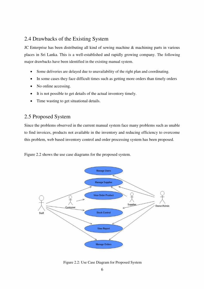
2.5 Proposed System
Since the problems observed in the current manual system face many problems such as unable
to find invoices, products not available in the inventory and reducing efficiency to overcome
this problem, web based inventory control and order processing system has been proposed.
Figure 2.2 shows the use case diagrams for the proposed system.
Figure 2.2: Use Case Diagram for Proposed System

7
2.6 Functional Requirements
Functional requirements “Defines a function of a system or its component. A function is
described as a set of inputs, the behavior, and outputs. Functional requirements may be
calculations, technical details, data manipulation and processing and other specific
functionality that define what a system is supposed to accomplish”[1].
2.6.1 User Management Module
Following shows the functions of user management module.
System should provide a facility to enroll and manage employees with the
system.(add, view, update, delete)
Admin should be able to manage user account types and provide privileges to them.
Employee will be able to login to the system
2.6.2 Report Generate Module
Following shows the functions of reporting module
Viewing and submitting periodic reports on the sale, purchase, distribution, stock and
human resources, and directly directed by director.
The system should allow to print the reports and documents.
2.6.3 Invoicing Module
Following shows the functions of invoicing module
The system should provide to generate invoices.
The system should allow the users to print the invoices.
2.6.4 Stock Control Module
Following shows the functions of stock control module,
The manager should be able to manage GRN.
There should be a facility to check the inventory stock levels.
The system should be provided to monitor updated events in inventory reports.

8
2.6.5 Order Module
Following shows the functions of invoicing module,
Customer will be able to place order
Owner will be able to accept & process
2.7 Non Functional Requirements
Non-Functional requirements are also important facts which we need to consider when
developing the system. Non-functional requirements describe the system properties and
constraints of the system. Those requirements are applied to the whole system, not only for
the individual parts of the system. If we do not consider about non-functional requirements
system can be useless [2].
The User interfaces should be simple and intuitive.
The system should be user friendly.
The system should be reliable.
The system should be accurate.
The system should be secured.
In case of software or hardware failure system should be recover and be up and
running without causing problems.
Availability - The system should be available at any given time. The system should also
allow the customers to access it when needed.
User Friendly – The system should provide button, link, and tool tip etc. then user can easy
to access.
Maintainability –System can modify and upgrade without any problem.
Performance - One of the most important non-functional requirements. How long system
response for given operation, processing time, how long it take to query some record and
display. This thing should be happen as immediately as possible to achieve better
performance.
Secure and safe - the system should provide enough security features in order to protect
business sensitive data. The user privileges should also be provided.
9
2.8 Existing Similar Systems
There are lots of online Ordering systems which were created by organizations for business
purposes. Those systems were basically built for market their readymade products and to do
their day to day operations. Most of these systems do not provide the option to customized
customer needs.
The distinct features of the proposed system are it provides the facility to customize customer
needs, order progress tracking, stock estimation etc.
Online ordering systems have many potential benefits. It can help customer to order product
through the internet, Provide all the product information as well as the order information,
Store all the necessary important data in a computer, manage data accurately and provide
necessary reports to customers, allow customers to make their payments online, etc..
The following systems are refers to some online ordering systems which have some related
similarities with the proposed system.
InFlow Inventory Software System
Figure 2.3 shows the logo of inflow inventory software system.
Inflow is desktop-based inventory management software that helps small and medium-sized
businesses in tracking inventory. Its other features include filling customer orders, reordering
stock, generating purchase orders and invoices, and creating customized reports [3].
Figure 2.3: inFlow Inventory Software

10
Inventory Track System
Figure 2.4 shows the logo of inventory track software system.
Easily track all inventory in your store and warehouse with inventory track. Track stock level
and get automatic restocking notification. Scan manufacturer barcodes or produce barcode
labels directly from inventory track [4].
Track stock level of your inventory
Receive automatic restock notification
Use existing items labels or print your own
Manage inventory information records
View activity logs and reports
Figure 2.4: Inventory Track Software System

11
CHAPTER 3 - DESIGN
3.1 Introduction
The consultants develop several aspects of your system during the design phase. The
consultants determine the overall, high-level design of your system. This part of the design
gives an overview of the entire system. Develop a program design during this part of the
design phase, the consultants break down the system into pieces that can be programmed.
Breaking down the system into manageable modules also makes changes easier to
implement. Small modules allow changes to be implemented more easily. Modules also
assist in efficiency and consistency, a well-designed module can be reused in multiple
parts of the system saving time and also ensuring that the same feature of a system looks
and performs the same way throughout the system. And during this phase of design
determine how the different modules will interface to present you with a coherent system
that is easy to use [5].
3.2 Alternate Solution
Alternate 1- The alternate solution for the proposed system is developing the stand-alone
system. Stand-alone systems can be used within single PC. It can’t access through online.
Stand-alone systems have many difficulties which are Customers cannot make orders in
online & search items in online.
Alternate 2- Purchasing commercial inventory management system and customized it to
company requirement. According to these system very expensive and some features does
not need to client. Considering all the facts finally decided to developed web based online
inventory management system.

12
3.3 Justification of the selected solution
A web based system is selected as the solution for the proposed system because of the
following features.
This project has a limited time, where developer must followed a rapid development
process.
A web based system enables the users to access the system remotely.
As web base systems are platform independence and it can be used in any different
platform. Therefore the system users can move to any platform they wish and that has
no deal with the system.
3.4 Design Approach
We used this system MVC architecture for development because MVC allows you to separate
business logic from your presentation layer. This "Separation of Concerns" allow you to
quickly find and edit portions of your code. It also enables easy reuse of your UI components
across your system.
Process of MCV architecture
Model view controller or MVC as it is popularly called, is a software design pattern for
developing web applications. A model view controller pattern is made up of the following
three parts
Model − the lowest level of the pattern which is responsible for maintaining data.
View − this is responsible for displaying all or a portion of the data to the user.
Controller − Software code that controls the interactions between the model and view.
13
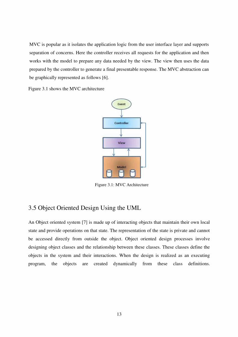
MVC is popular as it isolates the application logic from the user interface layer and supports
separation of concerns. Here the controller receives all requests for the application and then
works with the model to prepare any data needed by the view. The view then uses the data
prepared by the controller to generate a final presentable response. The MVC abstraction can
be graphically represented as follows [6].
Figure 3.1 shows the MVC architecture
3.5 Object Oriented Design Using the UML An Object oriented system [7] is made up of interacting objects that maintain their own local
state and provide operations on that state. The representation of the state is private and cannot
be accessed directly from outside the object. Object oriented design processes involve
designing object classes and the relationship between these classes. These classes define the
objects in the system and their interactions. When the design is realized as an executing
program, the objects are created dynamically from these class definitions.
Figure 3.1: MVC Architecture

14
3.5.1 Use Case Diagram for Web Based Inventory Control & Order Processing
System
Virtually all approaches to system development begin the modeling process with concept of a
use case. The following figure 3.2 show the top level use case diagram of the system.
The following figure 3.2 shows the top level use case diagram of the System.
.
3.5.2 Class Diagram for Web Based Inventory Control & Order Processing
System
Figure 3.3 shows the class diagram of the proposed system.
Figure 3.2: Top level Use Case Diagram of the System

15
Figure3.3: Class Diagram of the System
16
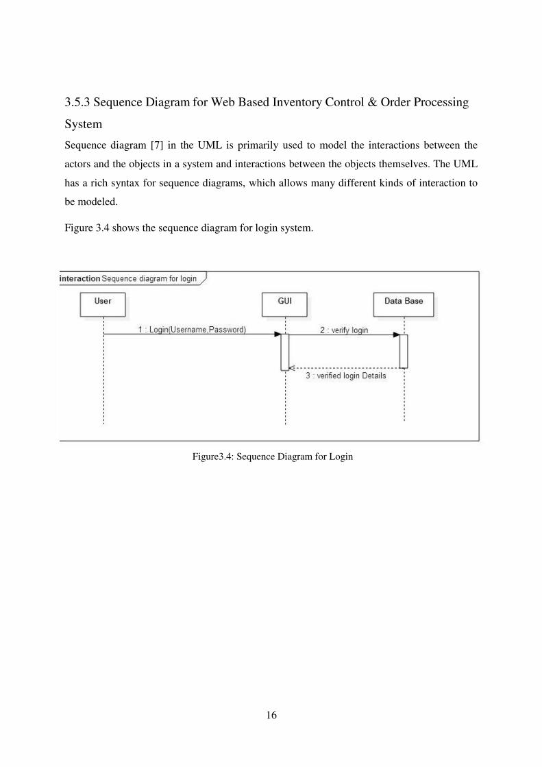
3.5.3 Sequence Diagram for Web Based Inventory Control & Order Processing
System
Sequence diagram [7] in the UML is primarily used to model the interactions between the
actors and the objects in a system and interactions between the objects themselves. The UML
has a rich syntax for sequence diagrams, which allows many different kinds of interaction to
be modeled.
Figure 3.4 shows the sequence diagram for login system.
Figure3.4: Sequence Diagram for Login
17
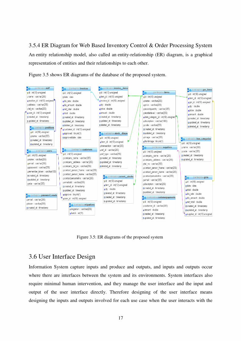
3.5.4 ER Diagram for Web Based Inventory Control & Order Processing System
An entity relationship model, also called an entity-relationship (ER) diagram, is a graphical
representation of entities and their relationships to each other.
Figure 3.5 shows ER diagrams of the database of the proposed system.
3.6 User Interface Design
Information System capture inputs and produce and outputs, and inputs and outputs occur
where there are interfaces between the system and its environments. System interfaces also
require minimal human intervention, and they manage the user interface and the input and
output of the user interface directly. Therefore designing of the user interface means
designing the inputs and outputs involved for each use case when the user interacts with the
Figure 3.5: ER diagrams of the proposed system

18
computer to carry out a task. When designing user interfaces for the Web based inventory
control order processing system following matters are considered.
Keep the Interface simple
All users of the system will be happy to avoiding unnecessary features and clear
everything.
Consistency
The way that information is arranged on forms, the names and arrangement of menu
items, the size and shape of icons, and the sequence followed to carry out tasks are
designed to be steady throughout the system.
Strategically use color and texture
The attention is directed away from items using color, light, contrast, and texture to
your benefits.
Familiarity
Users who are already familiar with the interface that is familiar to the user, will
increase the cordiality of the work flow.
Easy Navigation
Navigation between pages will be easy.
Error handling and forgiveness
The system will tolerate and prevent common and unavoidable human errors by expecting
where mistakes may occur and designing to prevent them. It will provide meaningful
messages when an error does occur. The proposed system will also permit users to review,
change and undo actions whenever necessary. Please refer User Documentation in Appendix:
C for more user interfaces.

19
3.6.1 The Home Page
Since the proposed system is a web based system which is going to serve both customer and
staff users the homepage is designed for the benefit of both sides.
figure 3.6 shows homepage of the proposed system.
Figure 3.6: Home page

20
3.6.2 Login Interface
The following figure 3.7 shows the login interface for users. Only authorized users can access
the system. If an invalid username or password has been submitted won’t be able log into the
system and error messages are displayed.
3.6.3 Administrator Home Page
The home page for system administrator’s account is displayed in figure 3.8 it is designed
according to the requirements of the client and has been studied by other similar web based
systems. The navigation bar on the left side of the page will be accessible to all administrators'
tasks.
Figure 3.8: Administrator Home Page
Figure 3.7: Login Interface

21
3.6.4 Interface for Add, Delete and Update Supplier
The following figure 3.9 interfaces which belong to administrator and it is use to add new
supplier, delete an existing supplier and edit the current supplier information. After every
deletion, or updating a feedback is given to user whether the modification updates the
database or not.
3.6.5 Data Entry Forms
There is several kind of data entry forms are used in the system. All the data entered to this
page is validated before doing any modification and relevant error messages are shown to
user. When user is assigned to particular task by administrator, staff has to enter data to the
system regarding that task. These data entry forms will provide interface for that figure 3.10 is
one of them.
Figure 3.9: Add new, Delete, Edit Interface
Figure3.10:Data Entry Form
22
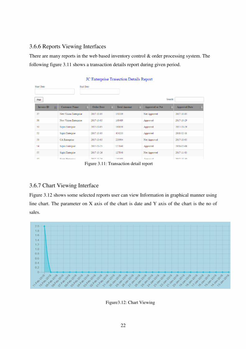
3.6.6 Reports Viewing Interfaces
There are many reports in the web based inventory control & order processing system. The
following figure 3.11 shows a transaction details report during given period.
3.6.7 Chart Viewing Interface
Figure 3.12 shows some selected reports user can view Information in graphical manner using
line chart. The parameter on X axis of the chart is date and Y axis of the chart is the no of
sales.
Figure 3.11: Transaction detail report
Figure3.12: Chart Viewing
23
CHAPTER 4 - IMPLIMENTATION
4.1 Introduction
The Implementation phase is when the end user of your software is foremost in your mind.
During this phase you create the documentation and tools the customer uses to make informed
decisions about how to deploy your software securely. To this end, the Implementation phase
is when you establish development best practices to detect and remove security and privacy
issues early in the development cycle [8].
4.2 Hardware and Software Requirement
This system has been developed using with under following configurations.
4.2.1 Hardware Requirements
1. Processor - Intel Core i3 CPU 1.90Ghz
2. Physical memory - 4.00GB DDR3 RAM
3. Hard disk drive capacity (HDD) - 500 GB
4. Key Board / Mouse
5. Monitor - 15.5 inches screen size with 1366 x 768 resolution
4.2.2 Software Requirements
Microsoft windows 7 X
XAMPP Server
Adobe Photoshop CS3
Notepad++
Google Chrome, Firefox
Star UML
24
4.3 Support Language and techniques
The system has been developed using the following languages and technologies.
HTML was used to build the web interface of the system.
CSS is used to define styles for your web pages, including the design, layout and
variations in display for different devices and screen sizes.
JavaScript is most commonly used as a client side scripting language. This means
that JavaScript code is written into an HTML page. When a user requests an HTML
page with JavaScript in it, the script is sent to the browser and it's up to the browser to
do something with it.
AJAX is a technique for creating fast and dynamic web pages. AJAX allows web
pages to be updated asynchronously by exchanging small amounts of data with the
server behind the scenes. This means that it is possible to update parts of a web page,
without reloading the whole page [9].
PHP (PHP: Hypertext Preprocessor) is a general-purpose scripting language that is
especially suited to server-side web development [10].The development of this system
was the main language which used to develop the entire system and its logic.
jQuery is a fast, small, and feature-rich JavaScript library. It makes things like HTML
document traversal and manipulation, event handling, animation, and Ajax much
simpler with an easy-to-use API that works across a multitude of browsers [11].In this
system jQuery is mostly used in reused components and as well as original coding.
MySQL was used for the creation of the all-important database.

25
4.4 Code and Main Modules of the System
System developed based on Laravel framework (MVC Framework).
Basic MVC architecture advertisements model view controller or MVC as it is popularly
called is a software design pattern for developing web applications. A model view
controller pattern is made up of the following three parts: Model - The lowest level of the
pattern which is responsible for maintaining data.
A Model, which represents the underlying, logical structure of data in a software
application and the high-level class associated with it. This object model does not contain
any information about the user interface.
A View , which is a collection of classes representing the elements in the user interface
(all of the things the user can see and respond to on the screen, such as buttons, display
boxes, and so forth)
A Controller, which represents the classes connecting the model and the view, and is used
to communicate between classes in the model and view.
Following figure 4.1 shows the MVC (Model-View-Control) Architecture
Figure 4.1: MVC Architecture
26
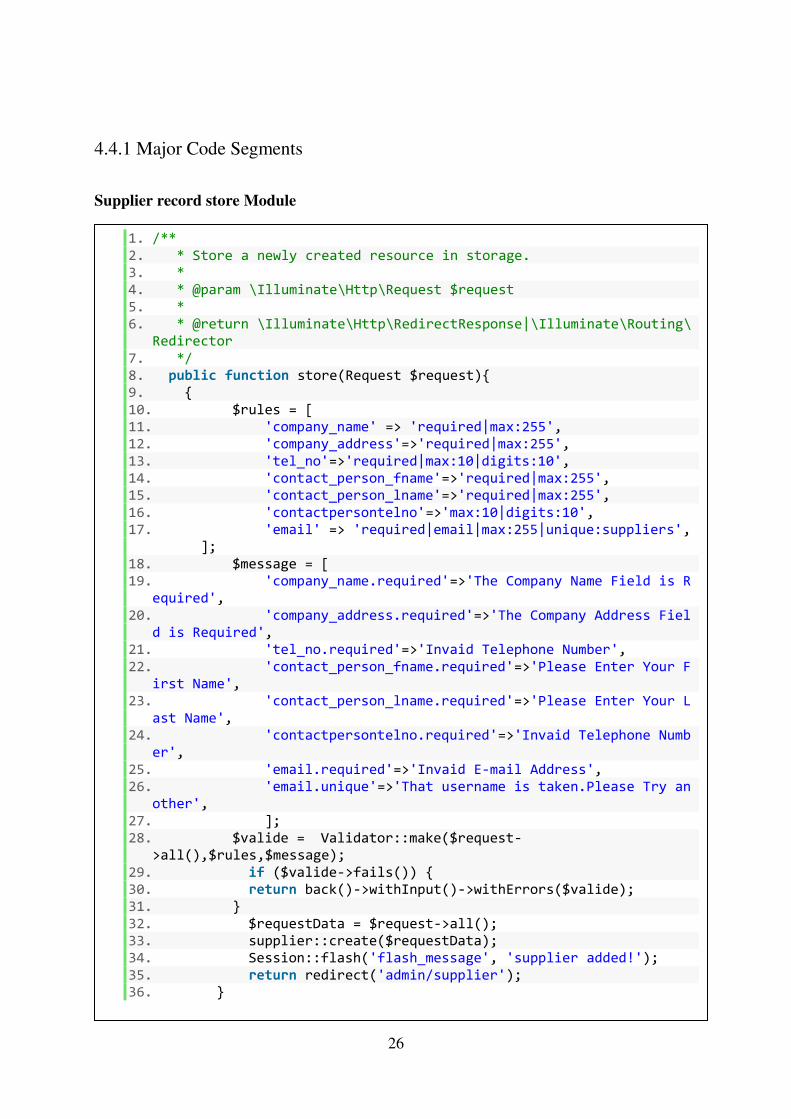
4.4.1 Major Code Segments
Supplier record store Module
Login Module
1. /** 2. * Store a newly created resource in storage. 3. * 4. * @param \Illuminate\Http\Request $request 5. * 6. * @return \Illuminate\Http\RedirectResponse|\Illuminate\Routing\
Redirector 7. */ 8. public function store(Request $request){ 9. { 10. $rules = [ 11. 'company_name' => 'required|max:255', 12. 'company_address'=>'required|max:255', 13. 'tel_no'=>'required|max:10|digits:10', 14. 'contact_person_fname'=>'required|max:255', 15. 'contact_person_lname'=>'required|max:255', 16. 'contactpersontelno'=>'max:10|digits:10', 17. 'email' => 'required|email|max:255|unique:suppliers',
]; 18. $message = [ 19. 'company_name.required'=>'The Company Name Field is R
equired', 20. 'company_address.required'=>'The Company Address Fiel
d is Required', 21. 'tel_no.required'=>'Invaid Telephone Number', 22. 'contact_person_fname.required'=>'Please Enter Your F
irst Name', 23. 'contact_person_lname.required'=>'Please Enter Your L
ast Name', 24. 'contactpersontelno.required'=>'Invaid Telephone Numb
er', 25. 'email.required'=>'Invaid E-mail Address', 26. 'email.unique'=>'That username is taken.Please Try an
other', 27. ]; 28. $valide = Validator::make($request-
>all(),$rules,$message); 29. if ($valide->fails()) { 30. return back()->withInput()->withErrors($valide); 31. } 32. $requestData = $request->all(); 33. supplier::create($requestData); 34. Session::flash('flash_message', 'supplier added!'); 35. return redirect('admin/supplier'); 36. }

27
Supplier record update Module – Edit the specified supplier record
Supplier delete Module - Remove the specified record from database
1. public function update($id, Request $request) 2. { 3. $rules = [ 4. 'company_name' => 'required|max:255', 5. 'company_address'=>'required|max:255', 6. 'tel_no'=>'required|max:10|digits:10', 7. 'contact_person_fname'=>'required|max:255', 8. 'contact_person_lname'=>'required|max:255', 9. 'contactpersontelno'=>'max:10|digits:10', 10. 'email' => 'required|email|max:255|unique:suppliers,
email,'.$id, 11. ]; 12. $message = [ 13. 'company_name.required'=>'The Company Name Field is
Required', 14. 'company_address.required'=>'The Company Address Fie
ld is Required', 15. 'tel_no.required'=>'Invaid Telephone Number', 16. 'contact_person_fname.required'=>'Please Enter Your
First Name', 17. 'contact_person_lname.required'=>'Please Enter Your
Last Name', 18. 'contactpersontelno.required'=>'Invaid Telephone Num
ber', 19. 'email.required'=>'Invaid E-mail Address', 20. ]; 21. $valide = Validator::make($request-
>all(),$rules,$message); 22. 23. if ($valide->fails()) { 24. return back()->withInput()->withErrors($valide); 25. } 26. $requestData = $request->all(); 27. $supplier = supplier::findOrFail($id); 28. $supplier->update($requestData); 29. Session::flash('flash_message', 'supplier updated!');
30. return redirect('admin/supplier'); 31. }
1. public function destroy($id) 2. { 3. supplier::destroy($id); 4. Session::flash('flash_message', 'supplier deleted!'); 5. return redirect('admin/supplier'); 6. }
28
4.4.2 Reused Modules
In order to achieve a better systematic and efficient way, the system's developing codes and
modules were followed.
Bootstrap framework
Bootstrap is a free and open-source collection of tools for creating websites and web
applications. It contains HTML and CSS based design templates for typography, forms,
buttons, navigation and other interface components, as well as optional JavaScript extensions.
jQuery Java Script Library
jQuery is a fast, small, and feature-rich JavaScript library. It makes things like HTML
document traversal and manipulation, event handling, animation, and Ajax much simpler with
an easy-to-use API that works across a multitude of browsers. With a combination of
versatility and extensibility, jQuery has changed the way that millions of people write
JavaScript [11].
In developing this system jQuery is used in throughout the system where it is appropriate
especially in handling Ajax calls.
jQuery UI
jQuery UI is a curated set of user interface interactions, effects, widgets, and themes built on
top of the jQuery JavaScript Library[12].
jQuery UI is used places where jQuery date picker [13] is used.
Chart.js
Simple, clean and engaging HTML5 based JavaScript charts. Chart.js is an easy way to
include animated, interactive graphs on your website [14].

29
CHAPTER 5 - EVALUATION
5.1 Introduction
Testing is the process of evaluating a system or its component with the intent to find whether
it satisfies the specified requirements or not. Further testing is executing a system in order to
identify any gaps, errors or missing requirements in contrary to the actual desire or
requirements [15].
5.2 Verification and Validation testing of a System
In software project management, software testing, and software engineering, verification and
validation (V&V) is the process of checking that a software system meets specifications and
that it fulfills its intended purpose. It may also be referred to as software quality control [16].
5.3 Test Plan
A test plan can be defined as a document describing the scope, approach, resources, and
schedule of intended testing activities. It identifies test items, the features to be tested, the
testing tasks, who will do each task and any risks requiring contingency planning [17].
5.3. 1 Objectives
The primary objective of test plan is to verify whether the web base inventory controls system
satisfy the requirements of JC enterprise company.
5.3.2 Assumptions
The actual data that client is going to input and test data are no difference at all.
The real web based environment and localhost has no difference.

30
5.3.3 Scope
5.3.3.1 Functions to be test
User login
Supplier register
Purchasing Order
report Generation
5.3.3.2 Non Functional Requirements not to be test
Security
Data is not very confidential and non-sensitive, so the security of the system is not checked.
Performance Since the system is not going to handle big volume of data at the same time the performance
of the system is not tested.
5.3.3.3 Browser Compatibility
The system will be tested on latest versions Fire fox and Google Chrome.
5.3.3.4 Platform Compatibility
The system will be tested on the Windows 7 and above other Windows Operating systems.
5.3.4 Test Process
5.3.4.1 Test Design and Execution Process
Understanding requirements
Requirements identified through the client's interview, document reviews and observations.
Preparing test cases
Test cases will be prepared base on the above understand requirements.
Preparing test matrix
The test matrix prepared to match respective requirements. This will ensure that each
requirement is tested during the evaluation.

31
Executing Test cases
The test cases are processed in the local environment based on planned test cases and test data
The test results will be on Appendix: E.
Defect Tracking and Reporting
Issues that found in execution will be tracked and after fixing them again they are re verified.
After fixing and retesting all the issues a full regression test will be done.
5.4 Testing Types
5.4.1 Unit testing
Unit testing is a software testing method by which individual units of source code, sets of one
or more computer program modules together with associated control data, usage procedures,
and operating procedures, are tested to determine whether they are fit for use [18].
5.4.2 Black Box testing
Black-box testing is a method of software testing that examines the functionality of an
application without peering into its internal structures or workings. This method of test can be
applied virtually to every level of software testing: unit, integration, system and acceptance.
It is sometimes referred to as specification-based testing [19].
5.4.3 White box testing
White-box testing (also known as clear box testing, glass box testing, transparent box testing,
and structural testing) is a method of testing software that tests internal structures or workings
of an application, as opposed to its functionality (i.e. black-box testing). In white-box testing
an internal perspective of the system, as well as programming skills, are used to design test
cases [20].

32
5.4.4 Integration testing
Integration testing (sometimes called integration and testing, abbreviated I&T) is the phase
in software testing in which individual software modules are combined and tested as a group
[21].
5.4.5 System Testing
System testing of software or hardware is testing conducted on a complete, integrated system
to evaluate the system's compliance with its specified requirements. System testing falls
within the scope of black-box testing, and as such, should require no knowledge of the inner
design of the code or logic.
As a rule, system testing takes, as its input, all of the "integrated" software components that
have passed integration testing and also the software system itself integrated with any
applicable hardware system(s) [22].
5.4.6 User acceptance Testing (Beta Testing)
User acceptance testing (UAT) consists of a process of verifying that a solution works for the
user. It is not system testing (ensuring software does not crash and meets documented
requirements), but rather ensures that the solution will work for the user (i.e., tests that the
user accepts the solution); software vendors often refer to this as "Beta testing" [23].
5.5 TEST CASES
A test case is a set of conditions or variables under which a tester will determine whether a
system under test satisfies requirements or works correctly. The process of developing test
cases can also help find problems in the requirements or design of an application. Generally
test cases include the test case title, inputs, expected results and the priority.
The following sections describe the modules tested and the relevant test cases.
33
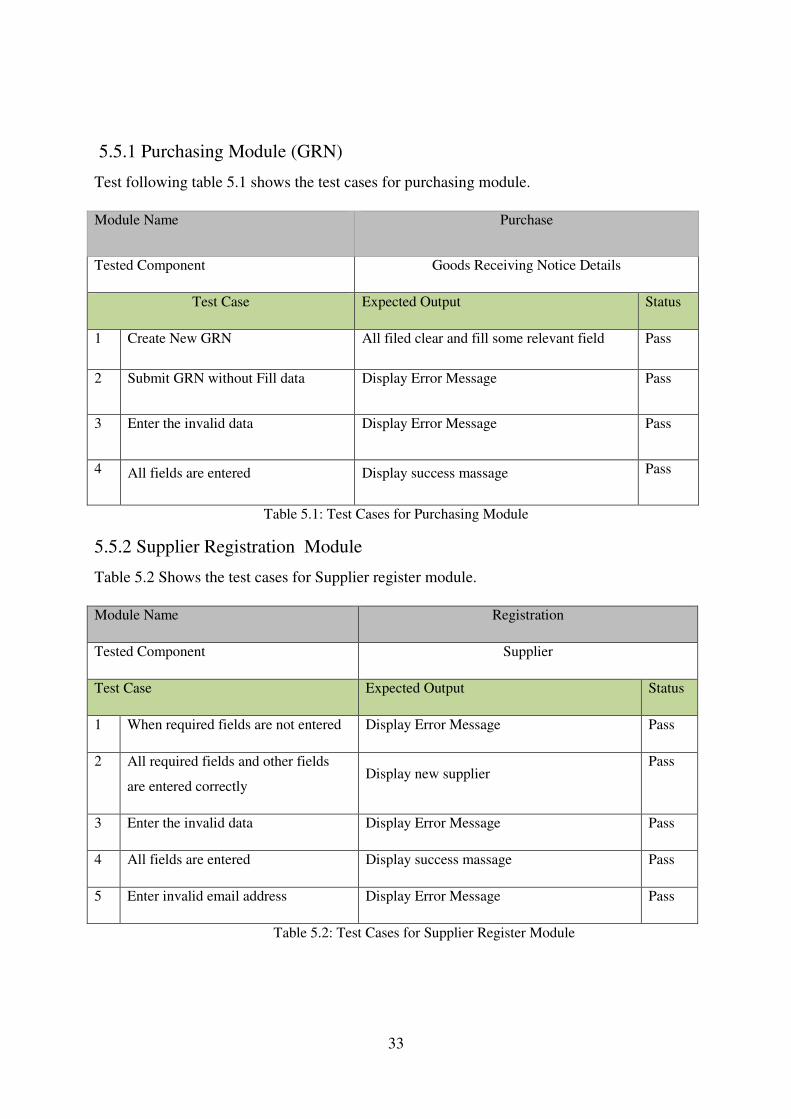
5.5.1 Purchasing Module (GRN)
Test following table 5.1 shows the test cases for purchasing module.
Module Name Purchase
Tested Component Goods Receiving Notice Details
Test Case Expected Output Status
1 Create New GRN All filed clear and fill some relevant field Pass
2 Submit GRN without Fill data Display Error Message Pass
3 Enter the invalid data Display Error Message Pass
4 All fields are entered Display success massage Pass
Table 5.1: Test Cases for Purchasing Module
5.5.2 Supplier Registration Module
Table 5.2 Shows the test cases for Supplier register module.
Module Name Registration
Tested Component Supplier
Test Case Expected Output Status
1 When required fields are not entered Display Error Message Pass
2 All required fields and other fields
are entered correctly Display new supplier
Pass
3 Enter the invalid data Display Error Message Pass
4 All fields are entered Display success massage Pass
5 Enter invalid email address Display Error Message Pass
Table 5.2: Test Cases for Supplier Register Module

34
5.5.3 User Management Module
Table 5.3 shows the test cases for user login.
Module Name Registration
Tested Component Supplier
Test Case Expected Output Status
1 Click login button without filled the username and
password
Display Error Message Pass
2 Enter invalid email Address Display Error Message Pass
3 Click login with valid email and no password Display Error Message Pass
4 Enter correct email which is exist the login table
with wrong password Display Error Message
Pass
5 Enter correct email and password Login to System Pass
Table 5.3: Test Cases for User Login
5.5.4. Print Report Module
Table 5.4 shows the test cases for report module.
Module Name Report Module
Tested Component Report Generate
Test Case Expected Output Status
1 Generate Report User can generate report Specific Criteria Pass
2 Generate Print User get Print all report Pass
Table 5.4: Test Cases for Report Module
5.6 ACCEPTANCE TEST
Acceptance Test was done after implementation of the System for JC Enterprise. Company
Staff who uses the system was operating real data. After accepting system, after accepting
system, it must be identified that the system is user friendly.

35
5.7 USER EVALUATION
Unit testing and system testing were done by developer using his own data set. When the
developer finished testing the system, few random users were selected to test the system.
Then this system gave to the client for acceptance testing. There for a questionnaire was
given to the 10 client side users. Figure 5.1 shows the summery result of that survey.
User Evaluation Form
User feedback results converted into a graphical evaluation chart. The following pie chart in
figure 5.2 provides the feedback in graphically.
Employee Feedback
Figure 5.1: User Evaluation Form
Figure 5.2: Employee Feedback
36
CHAPTER 6 - CONCLUTION
6.1 Overview
JC Enterprise Company is a prominent Swing Machine store in the Colombo District and
commences business as a traditional handbook. However, the business competition requires
some changes in business operations to improve the current situation in the marketplace to
simplify operations utilize resources and improve customer relationships. This was the
beginning of developing this inventory management system, a new business solution for
memory technology.
The developed system supports all operations related to inventory management.
Facilitate the storage of each item's items of customers. Users are not allowed to perform
fraudulent activity to ensure the integrity of the data. All documents, such as invoices,
payment vouchers, scheduled remittances, can be systematically generated. For business
analysis, the system provides daily transaction reports and management track record reports.
To improve customer relations, various services are provided to provide a better service to the
system. Without a stay in queues, the customer can get the outstanding amount in their
system. On-line profiles provide access to details of purchase orders. Customers are
automatically genetically informed about their payments. They will be able to find outward
billing, promotional activity through online systems.
The final result of this project is a highly secure, user friendly application that is remotely
organized by the organization. By studying other inventory systems, I was helped to develop a
more complete and efficient system. Compared to other methods, future development can be
designed to develop this system as a systematic automation system.
6.2 Critical Assessment of the Proposed System
It was satisfied with the system, such as the preparation of the production plan, reporting and
manipulation of production, as included with purchase order management. It will satisfy the
user by providing user performance, reliability, distribution, and user convenience. This
project will support productivity improvements with operational times and customer
satisfaction.

37
This system developed as a web system for the distribution nature. But it can be added to
some management issues, such as lower data transfer speeds and server disconnections
compared to previous systems.
Because stocks are always moving to the inventory location, the current system does not have
sub-locations. Therefore, sub-location manage can add unnecessary complexity to users.
Any specification untraced errors will be concentrated in the coming versions, which are
planned to be developed in the near future.
6.3 Problems Encountered while Developing the System
The main problem with the development of the system was the lack of basic knowledge of
languages on development tools and languages. Online tutorials, forums and books were used
to gain the n required level of knowledge.
6.4 Lessons learnt
Knowledge acquired throughout the project was really important. In addition, I was given this
experience by giving me a complete software development life-cycle from the feasibility
studies to end the project. This project gave me the opportunity to test and implement the
most important theories and technologies learned through the BIT degree program. When
assigning the project proposal did not have much of an idea on how to carry out this project.
A valuable knowledge of how to make a successful professional system development project
can be done when step-by-step takes place according to the guidelines provided by the
university. I learned to schedule my day-to-day activities according to a set schedule,
efficiently managing the time needed for development.
To help me improve system performance, I was able to find next technological discoveries
(AJAX, JQUERY, PHP, MYSQL, Laravel, and CSS) frameworks (MVC) and theories
(OO).Moreover, special efforts have been made to learn the MVC design pattern. Further
contributing to the work of the project helped me to develop technical skills and intellectual
skills.

38
6.5 Future Improvements
In the future it is expected to further improve the functional and non- functional requirements
for satisfying the client.
Registration Details send for mobiles of the users via SMS.
Credit Note, Debit Note Handling.
Online Payments
39
REFERENCES
[1] Functional Requirement [Online].Available:
http://en.wikipedia.org/wiki/Functional_requirement[Accessed: Jan 16, 2018].
[2] Non Functional requirements [Online].Available: https://en.wikipedia.org/wiki/Non-
functional_requirement[Accessed: Jan 16, 2018].
[3] Inflow Inventory: [Online].Available:https://reviews.financesonline.com/p/inflow-
inventory/[Accessed: Jan 16, 2018].
[4] Inventory Track [Online].Available:https://www.jollytech.com/products/inventory-
track/index.php[Accessed: Jan 18, 2018].
[5] Introduction [Online].Available:http://www.dragonpoint.com/whats-the-design-phase-ofa-
software-development-project/ [Accessed: Jan 16, 2018].
[6] MVC architecture [Online].Available:
https://www.tutorialspoint.com/struts_2/basic_mvc_architecture.htm [Accessed: Jan 16, 2018].
[7] J.W Satzinger, R. B Jackson and S. D. Burd, Object Oriented Analysis and Design, 4th
edition Cengage Learning India Private Limited, New Delhi, India, 2011.
[8] Implementation [Online].Available:https://msdn.microsoft.com/en-
us/library/windows/desktop/cc307416.aspx[Accessed: Jan 18, 2018].
[9] AJAX introduction https://www.w3schools.com/php/php_ajax_intro.asp[Accessed: Jan 16, 2018].
[10] Php.net, php. [Online] Available: http://www.php.net/ [Accessed: Jan 19, 2018].
[11] jQuery, What is jQuery [Online] Available: https://jquery.com/ [Accessed: Jan 22, 2018].
[12] jQuery user interface, jQuery UI. [Online] Available: http://jqueryui.com/ [Accessed: Jan
22, 2018].
[13] jQuery user interface,Datepicker.[Online]. Available: https://jqueryui.com/datepicker/
[Accessed: Jan 16, 2018].
[14] Chart.js [Online]. Available: http://www.chartjs.org/ [Accessed: Jan 23, 2018].
40
[15] Software Testing. [Online]. Available:
www.tutorialspoint.com/software_testing/software_testing_quick_guide.htm [Accessed: Jan 23,
2018].
[16] Verification and validation.Available:
https://en.wikipedia.org/wiki/Verification_and_validation[Accessed: Jan 18, 2018].
[17] Systems, software and technology, Test planning. [Online] Available: http://ifs.host.cs.st-
andrews.ac.uk/Books/SE9/Web/Testing/Planning.html [Accessed: Jan 27, 2018].
[18] Unit Testing- Wikipedia. Available: [Online].
https://en.wikipedia.org/wiki/Unit_testing[Accessed: Jan 27, 2018].
[19] Black Box Testing- Wikipedia. Available: [Online].
https://en.wikipedia.org/wiki/Black-box_testing [Accessed: Jan 27, 2018].
[20] Wikipedia. Available: [Online].
https://en.wikipedia.org/wiki/White-box_testing[Accessed: Jan 27, 2018].
[21] Integration testing - Wikipedia. Available: [Online].
https://en.wikipedia.org/wiki/Integration_testing[Accessed: Jan 27, 2018].
[22] System testing - Wikipedia https://en.wikipedia.org/wiki/System_testing[Accessed: Jan
27, 2018].
[23] Acceptance testing - Wikipedia: [Online].Available:
https://en.wikipedia.org/wiki/Acceptance_testing#User_acceptance_testing[Accessed: Jan 27,
2018].

41
Appendix A – System Documentation
The collection of documents that describes the information about how to setup the technical
environment from the start for further development of the project
Following table A.1 shows the developer personal computer Hardware specification.
Hardware Minimum requirement
PC Pentium IV, 1.0 GHz Processor or greater
RAM 1GB or more RAM
Hard Disk Space 1GB hard disk space
Internet Connection Ethernet connection or modem for accessing Internet
Printer Inject or Laser printer for printing reports
Table A.1: Hardware Requirements
Following table A.2 shows the developer personal computer Software specification.
Software Minimum requirement
Operating system Microsoft Windows 7 or higher
XAMPP Server 1GB or more RAM
Note Pad ++ Notepad++ 6.8.4 or upper version
LARAVAL 1GB or more RAM
Web Browser Google Chrome
Table A.2: Software Requirements

42
Download XAMPP from Apache Friends. Choose the download with the version of PHP that
you need
.https://www.apachefriends.org/index.html
Click on the downloaded file to install. Do not start the Control Panel.
In c:\xampp\apache\conf\httpd.conf change the following lines and then restart the XAMPP
console.
Step 1: Install XAMPP Server
XAMPP Control Panel
Installing XAMPP SERVER

43
Starting Apache & MySQL
Install Laraval
For managing dependencies, Laravel uses composer.
Make sure you have a Composer installed on your system before you install Laravel.
Step 1: Visit the following URL and download composer to install it on your system.
https://getcomposer.org/download/

44
Step 2: After the Composer is installed, check the installation by typing the Composer
command in the command prompt
Step 3: Create a new directory anywhere in your system for your new Laravel project. After
that, move to path where you have created the new directory and type the following
command there to install Laravel.
Composer create-project laravel/laravel –prefer-dist
Step 4: The above command will install Laravel in the current directory. Start the Laravel
service by executing the following command.
php artisan serve

45
Step 5: After executing the above command, you will see a screen as shown below:
Database installation
Open Google chrome then type “http://localhost/phpmyadmin/” on address bar.
In the phpMyAdmin window select “Databases” tab create a new database named
“jcenterprise.sql”
Next go to the “Import” tab and click on “Choose File” under File to Import section
and select the CD-ROM Drive: \Database\ jcenterprise.sql
Press “Go” button in the bottom of the page and this will finish the database
installation.

46
Appendix B – Design Documentation
Use Case Diagrams and Description
The following diagrams and description are the complete set of use cases created in the design
phase of the project. Figure B.1 shows the use case of the user management module
Use-Case Description for Add User
Use Case Name Add User
Actor Administrator / Owner
Overview
An administrator of the system add the user in the system
Pre conditions
1. Must be logged in to the system
2. User should have permission
3. Records should not be wrong
Flow of event
1. The actor logs in to the system.
2. System checks if the user has the authentication to add user.
3. Actor can add users.
Post condition
1. The user is added into the database.
Table B.1: Use Case Description for Add User
Figure B.1: Use Case of User Management

47
Use-Case Description for Edit User
Table B.2: Use Case Description for Edit User
Use Case Name Edit User
Actor Administrator / Owner
Overview
An administrator of the System modifies an existing User in the system
Pre conditions
1. Must be logged in to the system
2. User should have permission
3. Records should not be wrong
Flow of event
1. System display current list of users.
2. Administrator select user he/she want to edit.
3. System display corresponding information to the selected user.
4. Administrator edit information accordingly and submit
5. System update information
6. Use case end
Post condition
1. User information is changed.
2. View the edited user to the system.

48
Use-Case Description for Delete User
Table B.3: Use Case Description for Delete User
Use Case Name Delete User
Actor Administrator / Owner
Overview
A administrator of the System Delete an existing user in the system
Pre conditions
1. The Administrator is logged into the system
2. User should have permission
3. Records should not be wrong
Flow of event
1. Administrator select the user he/she want to delete
2. System checks if the user has the authentication to add user.
3. Administrator delete User
Post condition
1. Remove the user from the system.

49
Description of Supplier Management
Figure B.2 shows the use case diagram of the Supplier Module.
Use-Case Description for Register Supplier
Table B.4: Use Case Description for Register Supplier
Use Case Supplier Register
Actors Administrator/Owner, Accountant
Overview
Actor can add supplier to the system
Preconditions
1. Must be logged in to the system 2. User should have permission 3. Records should not be wrong.
Flow of events
1. The actor logs in to the system.
2. System checks if the user has the authentication to add user.
3. Actor can add new supplier in to the system.
Post conditions
1. The new supplier is added into the database.
Figure B.2: Use Case Diagram of the Supplier

50
Use-Case Description for View Supplier
Table B.5: Use Case Description for View Supplier
Description of Order Management
This module handles the placing order process. The customers can place an order. Admin or
owner can either change or confirm the order as well.
Figure B.3 shows the use case diagram of Order Management module.
Use Case Name View Items
Actor Administrator / Owner Accountant
Overview
Actor can view supplier to the system.
Pre conditions
1. Must be logged in to the system
2. User should have permission
3. Records should not be wrong
Flow of event
1. System display current list of Supplier.
Post condition
1. View supplier details to the system.
Figure B.3: Use case Diagram of Order Management Module
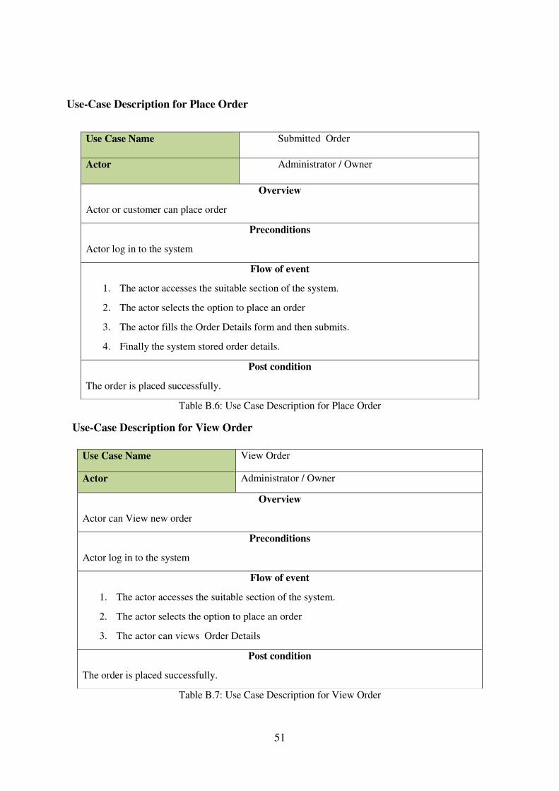
51
Use-Case Description for Place Order
Table B.6: Use Case Description for Place Order
Use-Case Description for View Order
Table B.7: Use Case Description for View Order
Use Case Name Submitted Order
Actor Administrator / Owner
Overview
Actor or customer can place order
Preconditions
Actor log in to the system
Flow of event
1. The actor accesses the suitable section of the system.
2. The actor selects the option to place an order
3. The actor fills the Order Details form and then submits.
4. Finally the system stored order details.
Post condition
The order is placed successfully.
Use Case Name View Order
Actor Administrator / Owner
Overview
Actor can View new order
Preconditions
Actor log in to the system
Flow of event
1. The actor accesses the suitable section of the system.
2. The actor selects the option to place an order
3. The actor can views Order Details
Post condition
The order is placed successfully.

52
Use-Case Description for Modify Order
Table B.8: Use Case Description for Modify Order
Activity Diagram for Order Module
Use Case Name View Order
Actor Administrator / Owner
Overview
Actor can Modify Order
Preconditions
Actor log in to the system
Flow of event
1. The actor logs in to the system.
2. System checks if the user has the authentication to add details.
3. Actor can modify orders
Post condition
View the modified order details.
Figure B.4: Activity Diagram for Ordering Model
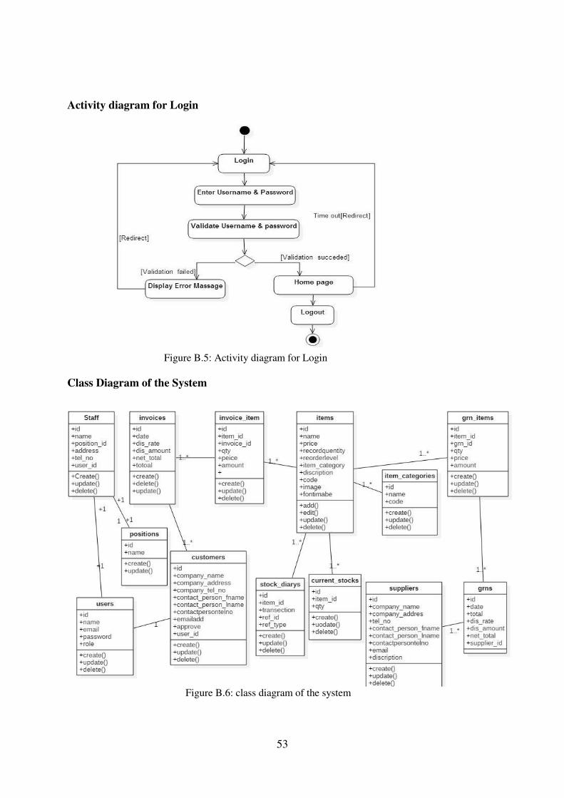
53
Activity diagram for Login
Class Diagram of the System
Figure B.5: Activity diagram for Login
Figure B.6: class diagram of the system

54
Appendix C – User Documentation
User documentation provides guidance regarding navigation within the system and how to use
its functionalities for the system users of web based inventory control and order processing
System. Eligibility to access system is available to administrator, customer, and staff.
Since there are 3 user levels with customized privileges, here in this document administrator’s
account is mainly described as it has all most all the functionalities and system privileges. For
other functionalities that administrator has nothing to deal with are described on the point of
relevant user.
C.1 Login Screen
Figure C.1 shows the login page of the “JC Enterprise Company”. Any authorized user can
login to the system using their user name and password. Any errors regarding the user login
will be displayed via meaningful error messages.
Figure C.1: Login Form

55
C.2 Home Page
The figure C.2 shows that home page of the system. User will be able to search for products,
log in to the system and perform several activities using this screen.
Figure C.2: Home Page

56
C.3 View Item Screen
Figure C.3 user can view all items on the system and a user can search by entering a key word
and filter products by price or category.
Figure C.3: View Items Screen
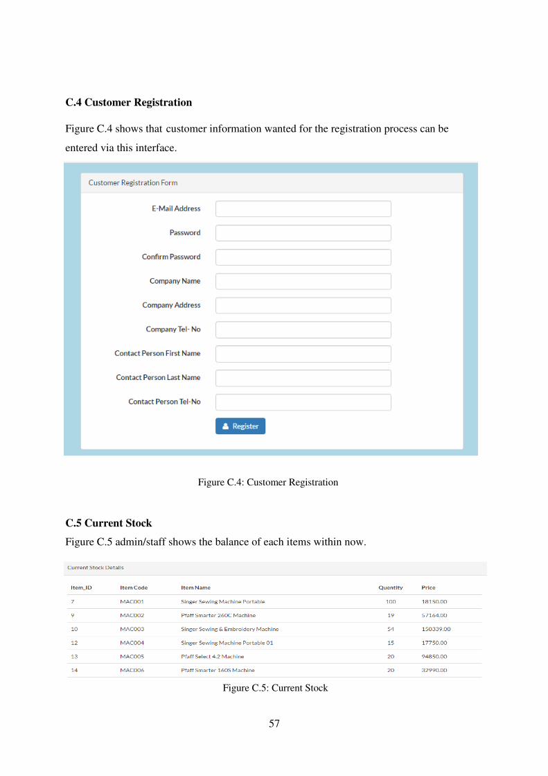
57
C.4 Customer Registration
Figure C.4 shows that customer information wanted for the registration process can be
entered via this interface.
C.5 Current Stock
Figure C.5 admin/staff shows the balance of each items within now.
Figure C.4: Customer Registration
Figure C.5: Current Stock

58
C.6 Approved Invoices
Figure C.6 shows admin/staff can see approved invoices in the system
C.7 Purchase Order
Figure C.7 shows that information about the goods you are looking for in the purchase.
Customer Name
Quantity
Cancel Item
Amount
Figure C.7: Purchase Order Form
Figure C.6: Approved Invoices

59
C.8 Goods Receiving Notice
Figure C.8 shows that goods receiving notice for the products.
C.9 Customer payment details
Figure C.9 shows that the customers in the system and their total payment amount.
Figure C.8: Goods Receiving Form
Figure C.9: Customer Payment Form

60
C.10 Pending Invoices
Figure C.10 shows invoices that have been added by the clerk and waiting for approval of the owner.
C.11 Invoice Form
Figure C.10: Pending Invoices
Figure C.11: Invoice Form

61
Appendix D – Management Reports
JC Enterrise company System provides many reporting facilities. System administrator can
generate folowing reports.
D.1 Transactional Details Report
Figure D.1 shows that all the trasection done customers.
D.2 Customer Details Report
Figure D.2 shows that indetails discription about all the customers in the ststem.
Figure D.1: Transactional Detail Report
Figure D.2: Customer Details Report
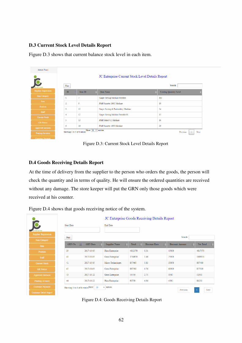
62
D.3 Current Stock Level Details Report
Figure D.3 shows that current balance stock level in each item.
D.4 Goods Receiving Details Report
At the time of delivery from the supplier to the person who orders the goods, the person will
check the quantity and in terms of quality. He will ensure the ordered quantities are received
without any damage. The store keeper will put the GRN only those goods which were
received at his counter.
Figure D.4 shows that goods receiving notice of the system.
Figure D.3: Current Stock Level Details Report
Figure D.4: Goods Receiving Details Report

63
D.5 Invoice Details Report
Your invoice details report gives you a comprehensive overview of all invoices you have
generated in a given time period.
Figure D.5 shows that current balance stock level in each item.
D.6 Overdue customer Report
Figure D.5: Invoice Details Report
Figure D.6: Overdue Customer Report
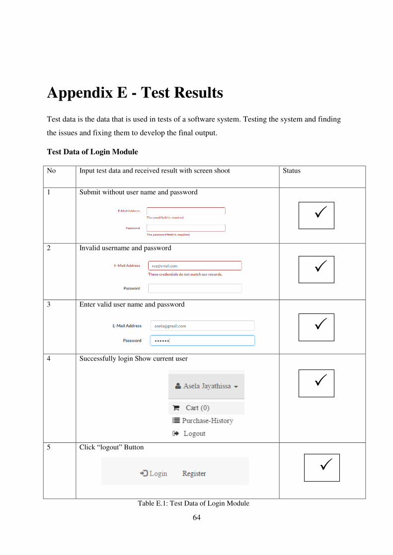
64
Appendix E - Test Results
Test data is the data that is used in tests of a software system. Testing the system and finding
the issues and fixing them to develop the final output.
Test Data of Login Module
No Input test data and received result with screen shoot Status
1 Submit without user name and password
2 Invalid username and password
3 Enter valid user name and password
4 Successfully login Show current user
5 Click “logout” Button
Table E.1: Test Data of Login Module

65
Test Data of Customer Registration Module
No Input test data and received result with screen shoot Status
1 Enter register button without fill the form
2 Invalid email address
3 Enter incorrect telephone number
Table E.2: Test Data of Customer Registration Module

66
Test Data of Add New Item to System
No Input test data and received result with screen shoot Status
1 Enter without fill data
2 Enter already exists Item code on system
3 Enter already exists Item name on system
4 Fill the form valid details and submit button
Table E.3: Test Data of add New Item to System

67
Appendix F – Code Listing
Codes of Modules
The system was developed based on OOP concepts. We used this system MVC architecture
for development because MVC allows you to separate business logic from your presentation
layer. For a complete and comprehensive look at the code of this project please refer to the
supplementary CD.
Controller Class (GrnControlle.php)
<?php
namespace App\Http\Controllers;
use App\Http\Requests;
use App\Http\Controllers\Controller;
use App\Grn;
use App\GrnItems;
use Illuminate\Http\Request;
use Session;
use Validator;
use App\Current_Stocks;
use App\Stock_Diarys;
class GrnController extends Controller
{
public function index(Request $request)
{
$keyword = $request->get('search');
$perPage = 25;
if (!empty($keyword)) {
$grn = Grn::with('supplier')->where('date', 'LIKE', "%$keyword%")
->orWhere('total', 'LIKE', "%$keyword%")
->orWhere('dis_rate', 'LIKE', "%$keyword%")
->orWhere('dis_amount', 'LIKE', "%$keyword%")
->orWhere('net_total', 'LIKE', "%$keyword%")
->paginate($perPage);
} else {
$grn = Grn::with('supplier')->paginate($perPage);

68
}
return view('grn.index', compact('grn'));
}
public function create()
{
$itemcategory= \App\Item::lists("name","id");
$company_name=\App\Supplier::lists("company_name","id");
return view('grn.create',compact('itemcategory','company_name'));
}
public function store(Request $request)
{
$requestData = $request->all();
$rules = [
'item_id.*.required',
'date' => 'required|date|date_format:Y-m-d',
'total'=>['required','regex:/^(?=.+)(?:[1-9]\d*|0)?(?:\.\d+)?$/'],
'dis_amount'=>['regex:/^(?=.+)(?:[1-9]\d*|0)?(?:\.\d+)?$/'],
'net_total'=>['required','regex:/^(?=.+)(?:[1-9]\d*|0)?(?:\.\d+)?$/'],
'supplier_id'=>'required',
'qty.*'=>['required','regex:/^(?=.+)(?:[1-9]\d*|0)?(?:\.\d+)?$/'],
'price.*'=>['required','regex:/^(?=.+)(?:[1-9]\d*|0)?(?:\.\d+)?$/'],
'amount.*'=>['required','regex:/^(?=.+)(?:[1-9]\d*|0)?(?:\.\d+)?$/'],
];
$message = [
'item_id.*.required'=>'Invalid Item',
'date'=>'The Date Field is Required',
'total.required'=>'Total Field is Required',
'net_total.required'=>'Invalid Net Total',
'supplier_id.required'=>'Please Select the supplier',
'qty.*.required'=>'Please Enter valid Quentity',
'price.*.required'=>'Invalid',
'amount.*.required'=>'Not Valid Amount',
];
$valide = Validator::make($request->all(),$rules,$message);

69
if ($valide->fails()) {
return response($valide->errors(),501);
}
try{
$grn=Grn::create($requestData);
$qty=$request->qty;
$item=$request->item_id;
$price=$request->price;
$amount=$request->amount;
for ($i=0; $i < count($item); $i++) {
GrnItems::create([
"item_id"=>$item[$i],
"price"=>$price[$i],
"qty"=>$qty[$i],
"amount"=>$amount[$i],
"grn_id"=>$grn->id,
]);
Current_Stocks::updatequentity($item[$i],$qty[$i],true);
Stock_Diarys::Create([
"item_id"=>$item[$i],
"transection"=>"Create New GRN",
"ref_id"=>$grn->id,
"ref_type"=>"GRN",
]);
}
return response("true",201);
}catch (Exception $Ex){
return response("Error",501);
}
}
public function show($id)
{
$grn = Grn::findOrFail($id);
return view('grn.show', compact('grn'));
}

70
public function edit($id)
{
$grn = Grn::findOrFail($id);
$itemcategory= \App\Item::lists("name","id");
$company_name=\App\Supplier::lists("company_name","id");
return view('grn.edit', compact('grn','company_name','itemcategory'));
}
public function update($id, Request $request)
{
$requestData = $request->all();
Session::flash('flash_message', 'Grn updated!');
$requestData = $request->all();
$rules = [
'item_id.*.required',
'date' => 'required|date|date_format:Y-m-d',
'total'=>['required','regex:/^(?=.+)(?:[1-9]\d*|0)?(?:\.\d+)?$/'],
'dis_amount'=>['regex:/^(?=.+)(?:[1-9]\d*|0)?(?:\.\d+)?$/'],
'net_total'=>['required','regex:/^(?=.+)(?:[1-9]\d*|0)?(?:\.\d+)?$/'],
'supplier_id'=>'required',
'qty.*'=>['required','regex:/^(?=.+)(?:[1-9]\d*|0)?(?:\.\d+)?$/'],
'price.*'=>['required','regex:/^(?=.+)(?:[1-9]\d*|0)?(?:\.\d+)?$/'],
'amount.*'=>['required','regex:/^(?=.+)(?:[1-9]\d*|0)?(?:\.\d+)?$/'],
];
$message = [
'item_id.*.required'=>'Invalid Item',
'date'=>'The Date Field is Required',
'total.required'=>'Total Field is Required',
'net_total.required'=>'Invalid Net Total',
'supplier_id.required'=>'Please Select the supplier',
'qty.*.required'=>'Please Enter valid Quentity',
'price.*.required'=>'Invalid',
'amount.*.required'=>'Not Valid Amount',
];
$valide = Validator::make($request->all(),$rules,$message);
if ($valide->fails()) {

71
return response($valide->errors(),501);
}
try{
$grn = Grn::findOrFail($id);
$grn->update($requestData);
foreach ($grn->grnitems as $key => $value) {
Current_Stocks::updatequentity($value->item_id, $value->qty,false);
}
GrnItems::where('grn_id',$grn->id)->delete();
$qty=$request->qty;
$item=$request->item_id;
$price=$request->price;
$amount=$request->amount;
for ($i=0; $i < count($item); $i++) {
GrnItems::create([
"item_id"=>$item[$i],
"price"=>$price[$i],
"qty"=>$qty[$i],
"amount"=>$amount[$i],
"grn_id"=>$grn->id,
]);
Current_Stocks::updatequentity($item[$i],$qty[$i],true);
Stock_Diarys::Create([
"item_id"=>$item[$i],
"transection"=>"Update GRN",
"ref_id"=>$grn->id,
"ref_type"=>"GRN",
]);
}
return response("true",201);
}catch (Exception $Ex){
return response("Error",501);
}
return redirect('grn');
}

72
public function destroy($id)
{
Grn::destroy($id);
Session::flash('flash_message', 'Grn deleted!');
return redirect('admin/grn'); }}
Model File
Grn Model (Grn.php)
<?php
namespace App;
use Illuminate\Database\Eloquent\Model;
class Grn extends Model
{
protected $table = 'grns';
protected $primaryKey = 'id';
protected $fillable = ['date', 'total', 'dis_rate', 'dis_amount', 'net_total','supplier_id'];
public function supplier(){
return $this->belongsTo('App\supplier');
}
public function GrnItems(){
return $this->hasMany('App\GrnItems');
}}
Create Grn
View Fie(Create.blade.php)
@extends('layouts.app')
@section('content')

73
<link rel="stylesheet" href="https://cdnjs.cloudflare.com/ajax/libs/bootstrap-
datepicker/1.6.4/css/bootstrap-datepicker.css" />
<div class="row">
@include('admin.sidebar')
<div class="col-md-9">
<div class="panel panel-default">
<div class="panel-heading">Create New GRN</div>
<div class="panel-body" >
<a href="{{ url('admin/grn') }}" title="Back"><button class="btn btn-warning btn-xs"><i
class="fa fa-arrow-left" aria-hidden="true"></i> Back</button></a>
<br />
<br />
<div class="alert alert-danger" hidden>
<ul>
</ul>
</div>
{{--Header Row--}}
{!! Form::open(["url" => 'admin/grn',"class" => 'form-horizontal'])!!}
<div class="row">
<div class="col-md-12">
<div class="form-group">
<label class="control-label col-md-2" for="">Date</label>
<div class="col-md-4 ">
<input type="text" class="form-control datepicker" id="date" placeholder=""name="date"
value="{{ date('Y-m-d') }}">
</div>
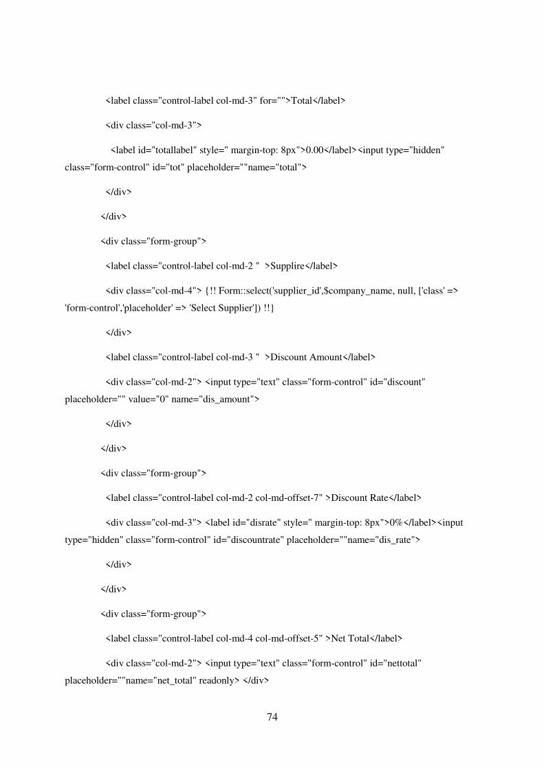
74
<label class="control-label col-md-3" for="">Total</label>
<div class="col-md-3">
<label id="totallabel" style=" margin-top: 8px">0.00</label><input type="hidden"
class="form-control" id="tot" placeholder=""name="total">
</div>
</div>
<div class="form-group">
<label class="control-label col-md-2 " >Supplire</label>
<div class="col-md-4"> {!! Form::select('supplier_id',$company_name, null, ['class' =>
'form-control','placeholder' => 'Select Supplier']) !!}
</div>
<label class="control-label col-md-3 " >Discount Amount</label>
<div class="col-md-2"> <input type="text" class="form-control" id="discount"
placeholder="" value="0" name="dis_amount">
</div>
</div>
<div class="form-group">
<label class="control-label col-md-2 col-md-offset-7" >Discount Rate</label>
<div class="col-md-3"> <label id="disrate" style=" margin-top: 8px">0%</label><input
type="hidden" class="form-control" id="discountrate" placeholder=""name="dis_rate">
</div>
</div>
<div class="form-group">
<label class="control-label col-md-4 col-md-offset-5" >Net Total</label>
<div class="col-md-2"> <input type="text" class="form-control" id="nettotal"
placeholder=""name="net_total" readonly> </div>

75
</div>
<hr>
</div>
<table class="table table-bordered">
<thead>
<tr><button type="button" class="btn btn-primary" id="add">Add New</button></tr>
<tr >
<th>Item ID</th>
<th>Quentity</th>
<th>Price</th>
<th>Amount</th>
<th>Action</th>
</tr>
</thead>
<tbody>
<tr>
<td>{!! Form::select('item_id[]',$itemcategory, null, ['class' => 'form-control
items','placeholder' => 'Select Item']) !!}</td>
<td ><input type="number" class="form-control text-right cal qty" id="qty"value="0.00"
name="qty[]" ></td>
<td><input type="number" class="form-control text-right cal price" id="price"
value="0.00"readonly name="price[]"></td>
<td><input type="number" class="form-control text-right amount" id="amount" readonly
name="amount[]"></td>
<td><button type="button" class="btn btn-danger center-block">X</button></td>
</tr>
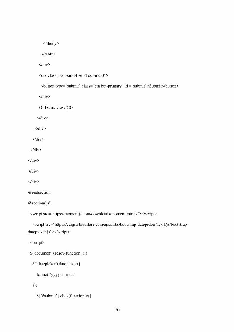
76
</tbody>
</table>
</div>
<div class="col-sm-offset-4 col-md-3">
<button type="submit" class="btn btn-primary" id ="submit">Submit</button>
</div>
{!! Form::close()!!}
</div>
</div>
</div>
</div>
</div>
</div>
</div>
@endsection
@section('js')
<script src="https://momentjs.com/downloads/moment.min.js"></script>
<script src="https://cdnjs.cloudflare.com/ajax/libs/bootstrap-datepicker/1.7.1/js/bootstrap-
datepicker.js"></script>
<script>
$('document').ready(function () {
$('.datepicker').datepicker({
format:"yyyy-mm-dd"
});
$("#submit").click(function(e){

77
e.preventDefault();
formdata= $("form").serializeArray();
$.ajax({
url :"{{ url('admin/grn') }}",
data:formdata,
type:"POST",
}).done(function(){
alert("Success");
location.reload();
$(".alert-danger").hide();
}).fail(function(data){
$(".alert-danger ul li").remove();
$.each(data.responseJSON,function(index,value){
$(".alert-danger ul").append("<li>"+value+"</li>")
})
$(".alert-danger").show();
})
});
$("#tot, #discount").on("keydown keyup ", function() {
sub();
disrate(); });
$("#submit").click(function(){
$("form").submit();
})
$("#add").click(function(){

78
tr=$(".table tbody tr:first")
clonetr=tr.clone()
clonetr.find("input[type='number']").val("0.00")
$(".table tbody tr:last").after(clonetr)
})
$(".table").on("keyup",".cal",function(){
tr=$(this).parent().parent()
calamount(tr)
disrate()
})
$(".table").on("click",".btn-danger",function(){
tr=$(this).parent().parent()
if($(".table tbody tr").length>1){
tr.remove()
totup();
sub();
disrate();
}
});
$(".table").on("change",".items",function(){
tr=$(this).parent().parent()
itemno=$(this).val()
$.ajax({
url:"{{ url('item-price')}}",
data:{itemId:itemno,_token:"{{ csrf_token() }}"},

79
type:"POST",
}).done(function(data){
tr.find(".price").val(data);
calamount(tr);
}).fail(function(data){
alert("Fail");
})
}) });
</script>
<script type="text/javascript">
function calamount(tr){
qty=tr.find(".qty").val()
price=tr.find(".price").val()
amount=qty*price
tr.find(".amount").val(amount);
totup();
sub(); }
function totup(){
sum=0.00;
$(".table tbody tr").each(function(){
amount =$(this).find(".amount").val();
sum=sum+parseFloat(amount); })
$("#totallabel").text(sum);
$("#tot").val(sum);
}

80
function sub() {
var tot = document.getElementById('tot').value;
var dis = document.getElementById('discount').value;
var nettotal = parseFloat(tot) - parseFloat(dis);
document.getElementById('nettotal').value = parseFloat(nettotal);
}
function disrate(){
var tot = document.getElementById('tot').value;
var dis = document.getElementById('discount').value;
var disrate = parseFloat(dis) /parseFloat(tot)*100;
document.getElementById('discountrate').value = parseFloat(disrate).toFixed(2);
$('#disrate').html(parseFloat(disrate).toFixed(2)+"%")
}
</script>
@endsection

81
Update Cart Total
Save to Invoice
1. public function cartupdate(Request $request){ 2. $rowId = $request->id; 3. $qty= $request->qty; 4. $line = Cart::get($rowId); 5. // dd(); 6. try { 7. $item = Item::findOrFail($line->id); 8. $current= Current_Stocks::where('item_id',$item->id)->first()->qty; 9. if($current<$request->qty){ 10. return Response::json(['error'=>"Out Of Stock"],402) ; 11. } 12. Cart::update($rowId,$qty); 13. return Response::json(['msg'=>"sucess",'count'=> Cart::content()-
>count()],200) ; 14. } catch (\Exception $e) { 15. return Response::json(['error'=>$e->getMessage()],401) ; 16. } 17. }
1. public function saveToInvoice(){ 2. // dd(str_replace(',','',Cart::total())); 3. // dd('aaaaa'); 4. $invoiceItem=[]; 5. $user=Auth::user(); 6. $cart=cart::content(); 7. $total=0; 8. foreach ($cart as $row){ 9. $itemId=$row->id; 10. $current= Current_Stocks::where('item_id',$itemId)->first()->qty; 11. $cartqty=$row->qty; 12. if($current<$cartqty){ 13. return Response::json(['error'=>"Out Of Stock"],402) ; 14. }else{ 15. $total+=$row->qty*$row->price; 16. $invoiceItem[]=['item_id'=>$row->id,'qty'=>$row->qty,'price'=>$row-
>price,'amount'=>$row->qty*$row->price]; 17. } 18. } 19. $invoice=Invoices::create([ 20. 'date'=>date('Y-m-d'), 21. 'dis_rate'=>0, 22. 'dis_amount'=>0, 23. 'net_total'=>$total, 24. 'total'=>$total, 25. 'customer_id'=>$user->Customer->id, 26. ]); 27. foreach ($invoiceItem as $row){ 28. $invoiceitem=Invoice_Items::create([ 29. 'item_id'=>$row['item_id'], 30. 'invoice_id'=>$invoice['id'], 31. 'qty'=>$row['qty'], 32. 'price'=>$row['price'], 33. 'amount'=>$row['amount'], 34. ]);

82
Transaction report
1. public function gettransectionData(Request $request){ 2. $transectionreport=\App\Invoices::with('Customer')->where( 3. function($q) use ($request){ 4. // dd($request->enddate); 5. if($request->startdate){ 6. $q->whereDate('date','>=',$request->startdate); 7. } 8. if($request->enddate){ 9. $q->whereDate('date','<=',$request->enddate); 10. } 11. } 12. )->get(); 13. return Datatables::of($transectionreport)-
>editColumn('approved',function($rows) { 14. if($rows->approved==1){ 15. return('Approved'); 16. }else{ 17. return('Not Approved'); 18. } 19. })->make(true); 20. }
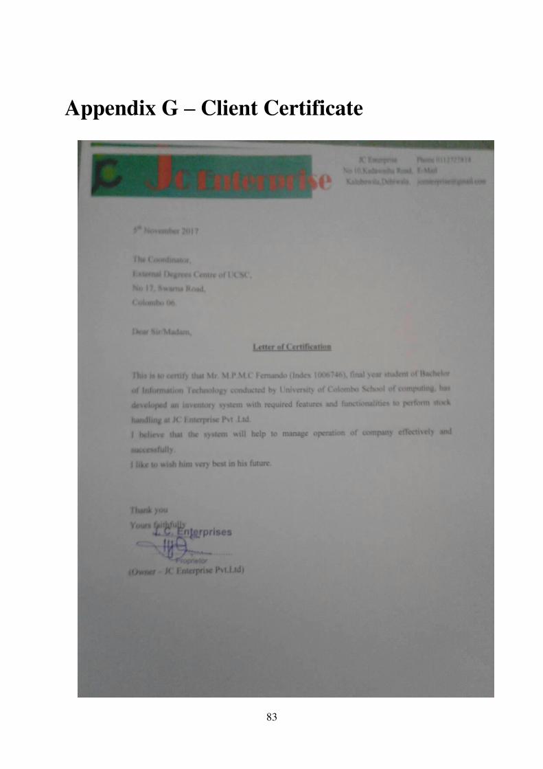
83
Appendix G – Client Certificate

84
Glossary
A
Ajax - Asynchronous JavaScript
Technology and XML
Apache server - This is a HTTP web
server which is developed and maintained
by the Apache software foundation
C
Cascading Style Sheets (CSS) – This is a
language that is used to format the content
of web pages
D
Database – a comprehensive collection of
related data.
E
Entity – a single objet about which data
can be stored.
H
Hyper Text Markup (H.T.M.L) - This is a
predominant markup language for web
pages
J
Java script - This is an object-oriented
scripting language, which supports
prototyping
I
Integration – an act or instance of
combination into an integral whole
M
Module – a separable component.
P
PHP - Hypertext Preprocessor, which is a
powerful server side scripting language
S
Server – something that serves or is used
in serving
Script – a program written in a scripting
language.
V
Validation – to make confirm
Verification – the act of verifying

85
Index
A
Activity Diagram........... x,57,58,89
D
Database........................ iii,
14, 16,26,29,33,37,76,88
E
Entity..........................v, 33,88
I
Integration...........viii, 16, 41, 42,
51, 88
M
Module.................vii,viii,x,19,22,25,29
,37,38,41,42,43,44,45.57,68,69,71,88
P
Procedures.........40
R
Report…………vi,vii,viii,ix,x,xi,12,13,14,16,18,19,20,44,45,46,51,64,65,66
S
Server.............iii, 35, 47,51,52,87
Script.............. v, 79,82,83,87
U
User Interface…………...v, vii, 23, 33
V
Validation.......vii, 40, 49