Embed Size (px)
Citation preview

International Status of Molten Carbonate Fuel Cell (MCFC)Technology
S. McPhail, A. Moreno, R. Bove
Report RSE/2009/181

RICERCA SISTEMA ELETTRICO
International Status of Molten Carbonate Fuel Cell (MCFC) Technology
S. McPhail, A. Moreno, R. Bove
Report RSE/2009/181
Ente per le Nuove tecnologie, l’Energia e l’Ambiente
INTERNATIONAL STATUS OF MOLTEN CARBONATE FUEL CELL (MCFC) TECHNOLOGY
S. McPhail, A. Moreno (ENEA)
R. Bove (JRC – IE, Petten, the Netherlands)
Gennaio 2008
Report Ricerca Sistema Elettrico
Accordo di Programma Ministero dello Sviluppo Economico - ENEA
Area: Produzione e fonti energetiche
Tema: Celle a combustibile per applicazioni stazionarie cogenerative
Responsabile Tema: Angelo Moreno, ENEA
3
Indice
1. Introduction 5
2. Molten Carbonate Fuel Cells: state of the art in the world 7
2.1 FuelCell Energy (FCE) 8
2.2 CFC Solutions GmbH 10
2.3 Ansaldo Fuel Cells (AFCo) 13
2.4 Ishikawajima-Harima Heavy Industries 15
2.5 KEPCO (KEPRI) and POSCO Power (RIST) 16
2.6 GenCell Corporation 18
3. Achievements and demonstration systems in the world 19
3.1 Fuel Cell Energy (USA) and CFC Solutions (Germany) 19
3.2 Ansaldo Fuel Cells (Italy) 21
3.3 Ishikawajima-Harima Heavy Industries (Japan) 23
3.4 KEPCO (KEPRI) and Posco Power (Korea) 25
3.5 GenCell Corporation (USA) 25
4. Potential customers and market 26
5. Concluding remarks 29
Annex – MCFC technology explained 30
A1. General features 31
A2. Materials state of the art 32
A3. Stack and balance of plant design 33
References 38
4
Acknowledgements The authors would like to thank all the contributors to this report. In particular,
information was provided by Mauro Scagliotti from CESI Ricerche, Biagio
Passalacqua and Arturo Torazza from Ansaldo Fuel Cells (Italy), Manfred Bischoff
and Gerhard Huppmann from CFC Solutions GmbH (Germany), Mohammad
Farooque from FuelCell Energy (USA), Dan Connors from GenCell Corporation
(USA), Kazumi Tanimoto from National Institute of Advanced Industrial Science and
Technology (Japan), Yoshihiro Mugikura from CRIEPI (Japan), Tae-Hoon Lim and
Sung Pil Yoon from KIST (South Korea). The north-American MCFC developers
acknowledge the support of the Department Of Energy over the years.

5
1. Introduction
Molten Carbonate Fuel Cells (MCFC) are currently being demonstrated in several sites
around the world. The typical power size is of several hundreds kWs, however, a 40-
125 kW MCFC system for mid size commercial, industrial and municipal applications
was developed by GenCell Corporation, and multi-MW systems are going to be
demonstrated in Europe [1], USA [2] and Japan [3].
Although there are demonstration programs all around the world, a strong R&D activity
is also being undertaken by R&D organizations, industrial companies, and universities.
In fact, there are still technical issues to solve before MCFC can penetrate the market
and compete with traditional energy systems. In particular, increasing useful service life
and reducing costs represent two important priorities upon which R&D is focused.
Durability is limited by corrosion within the cell components, electrolyte loss and due to
dissolution of the cathode into the cell matrix, eventually resulting in nickel shorting of
the two electrodes. While increasing the stack durability also implies decreasing the
system operating and maintenance (O&M) costs, including that of stack replacement,
other cost reduction activities are needed. These include increasing power density (to
reduce investment cost maintaining equal power yield), and exploring less expensive
manufacturing processes. In addition, mass production will contribute substantially to
cost reduction.
In the present paper, a review is offered of the current status of MCFC systems
development and application in the world through the extensive demonstration activities
of the main players in the field. But before that, two important questions should be
addressed, namely:
Why Molten Carbonate Fuel Cells?
The MCFC offers high electric energy conversion efficiency (about 50% based on
Lower Heating Value) in a simple cycle configuration, so that it can significantly reduce
the exploitation of non-renewable as well as renewable energy sources.

6
In addition, for equal power production, a high efficiency is translated into reduced
carbon dioxide emissions.
The MCFC operates at about 650 °C, thus, differently from low temperature fuel cells,
no precious metal is required as the fuel catalyst. Together with productions cost saving,
the main consequence of this is that carbon monoxide is not a poisoning element, but,
on the contrary, that it can be used as a fuel. This peculiarity allows the utilization of a
variety of CO-containing fuels, such as hydrocarbons, syngas derived from biomass or
coal, landfill gas, gas derived by industrial or agricultural by-products.
Does the MCFC require a hydrogen economy?
As mentioned above, the MCFC can operate on a variety of fuels, thus supporting a
better security of supply. Hydrogen is one of the fuels that the MCFC can employ, but it
is not the sole fuel. Actually, MCFCs have primarily been developed to be operated on
natural gas. At present, for economical and ecological reasons, there is a strong interest
towards the use of secondary fuels, of which biogas produced from anaerobic digestion
of renewable resources is an important example. Due to the lack of a hydrogen
infrastructure, no company is currently planning any demonstration of MCFC power
plants on hydrogen. In the eventual case of an hydrogen economy, however, the MCFC
can efficiently convert hydrogen into electricity, like all fuel cell types.
7
2. Molten Carbonate Fuel Cells: state of the art in the world
Fuel cell systems based on MCFC technology are under development in Italy, Japan,
Korea, USA and Germany. Since the 1990s, MCFC systems have been tested in field
trials in the range between 40 kWel and 1.8 MWel.
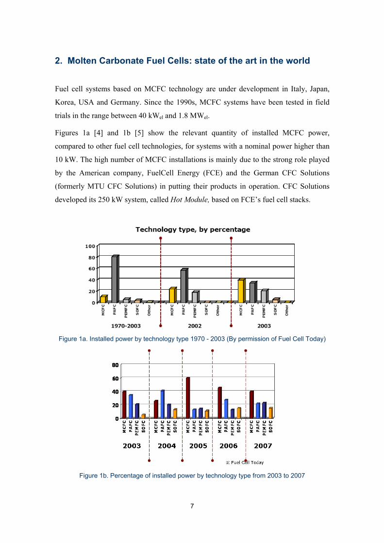
Figures 1a [4] and 1b [5] show the relevant quantity of installed MCFC power,
compared to other fuel cell technologies, for systems with a nominal power higher than
10 kW. The high number of MCFC installations is mainly due to the strong role played
by the American company, FuelCell Energy (FCE) and the German CFC Solutions
(formerly MTU CFC Solutions) in putting their products in operation. CFC Solutions
developed its 250 kW system, called Hot Module, based on FCE’s fuel cell stacks.
Figure 1a. Installed power by technology type 1970 - 2003 (By permission of Fuel Cell Today)
Figure 1b. Percentage of installed power by technology type from 2003 to 2007

8
Figures 1a and 1b also show that, during the period 1970-2003, Phosphoric Acid Fuel
Cells (PAFC) covered a dominant role for this power range, while in the last two years
many more MCFC units have been installed.
Six developers of MCFC technology are considered as the major in the world:
1. FuelCell Energy (FCE, USA)
2. CFC Solutions (Germany)
3. Ansaldo Fuel Cells (AFCo, Italy)
4. Ishikawajima-Harima Heavy Industries (IHI, Japan)
5. POSCO/KEPCO consortium and Doosan Heavy Industries (Korea)
6. GenCell Corportation (USA).
A brief description of them follows.
2.1 FuelCell Energy (FCE) is a world leader in the development and manufacture of
high efficiency fuel cells for clean electric power generation with products ranging from
300 kW to 2.4 MW and has been a fuel cell technology developer for over 30 years.
FCE has the biggest high temperature fuel cell manufacturing plant currently
operational, in Torrington, CT, with a capacity of 50 MW/year. Its headquarters are
located in Danbury, CT (USA).
As of 2007, close on 40 FCE
power plants have been installed
in USA for a total of 11.5 MW,
15 in Asia (mainly through the
sales right agreement with
partners Marubeni Corporation,
Japan, in place since 2001 and
renewed in May 2006)
amounting to 8.5 MW, and 12 in
Europe (the latter being CFC
plants with FCE technology, see also paragraph 2.2), corresponding to about 4.5 MW.
Figure 2 depicts a picture of the 1 MW King County Power Plant (Renton, WA),
operated on biogas from a waste water digester.
Figure 2. King County Power Plant (courtesy of FCE)

9
Product characteristics
FCE has developed three products:
• DFC® 300MA (300 kW)
• DFC® 1500 (1.2 MW)
• DFC® 3000 (2.4 MW)
Their common characteristics are:
o High temperature, high efficiency, carbonate fuel cell power plants for base load
commercial and industrial applications
o Certifications for product safety, interconnection, performance and installation
o High value waste heat by-product for cogeneration
o Internally generated hydrogen from readily available fuels such as natural gas
o Quiet operation: no moving parts incorporated in the generating mechanism
o Very low emissions (NOx< 0.3 ppmv, SOx< 0.01 ppmv, CO< 10 ppmv, VOC<
10 ppmv)
FCE installations are operating at customer sites today. In addition to the above
developed products, FCE is targeting two future systems:
• Shipboard fuel cell system that would run on diesel fuel and provide “hotel”
(non-propulsion) power to a new class of Navy ships.
• DFC-ERG (Direct Fuel Cell-Energy Recovery Generation), a hybrid concept
combining the Direct Fuel Cell (DFC®) and an unfired gas turbine. The fuel cell
is coupled with an upstream expansion turbine which reduces high-pressure gas
streams for gas transport to end-users (“let-down stations”, as in long-distance
gas pipelines) and generates electricity. Some of the expanded gas is then
converted in an MCFC to create further electricity and reheat the gas cooled by
the expansion process. In this way, a combined electrical efficiency of 60% can
be achieved.

10
2.2 CFC Solutions GmbH in Ottobrunn near Munich (Germany), a Tognum Group
company, develops and now markets an environmentally-friendly solution for
decentralized and efficient power supply applications, based on carbonate fuel cells.
CFC Solutions has considered the low carbon dioxide or carbon-neutral production of
electrical and thermal energy always as a main target; therefore the use of biogenic fuels
or residual gases as primary energy sources has played an important role at the
development stage already.
HotModule type fuel cell plants currently provide an output of approx. 250 kW
electrical and 170 kW thermal. The electrical efficiency in AC applications is almost
50%. Within the cells, the electro-chemical process runs at around 600 to 650 °C. This
high operating temperature allows:
• the transformation of hydrocarbons into hydrogen (internal reforming) to take
place within the cells
• the use of nickel as an inexpensive catalyst material
• the extraction of useful heat at elevated temperatures.
Typically the heat can be utilized as high-temperature heat at 400 °C and as low-
temperature heat at 60 °C.
The HotModule owes its name to the design of the plant: all “hot” parts – including the
fuel cell stack – are housed in one vessel. A key feature of the HotModule is its
operation with the fuel cell stack in a horizontal position. This enables feeding the fuel
gas from below while the weight of the stack automatically seals off the stack on the
fuel gas side. The HotModule is suitable for operations with natural gas, biogas, sewage
gas and syngas, as well as methanol.
Prototypes, projects and experiences
The first HotModule installations were put into operation by 1999, running on natural
gas as fuel. In the meantime the HotModules have proven their suitability also for
methanol, sewage gas and biogas in continuous operation. They are also suitable for
dual-fuel systems, which allow a quick change from one fuel to another, like natural gas
to methanol or visa versa, so that one energy source can be held in reserve.

11
Up to now (beginning of 2008) CFC Solutions has installed more than 20 HotModules
in Europe. Application fields are industry, hospitals, sewage works, biogas plants, dis-
trict heating systems and computer centres or telecommunications installations. These
plants have successfully com-
pleted a total of 300,000
operating hours (i.e. a
cumulative total of 35 operat-
ing years). The durability of
the HotModule has been
demonstrated in a clinic
application, where 30,000
operating hours using one
single fuel cell stack have
been achieved.
Latest product developments
CFC Solutions is currently expanding the product range: through modifications to the
original HotModule design, power plant systems with higher capacities become
available, based on standardised components. The HM300 product line can be
manufactured in a range from around 250 kW to 500 kW by equipping the modules
with stacks containing a variable number of fuel cells. In the medium term (see product
line overview at end of text), HotModule systems in the Megawatt range will become
available.
The synergies within the Tognum Group also allow the implementation of hybrid
systems by combining the HotModule with the stationary internal combustion engine-
driven CHP plants supplied by the sister company MDE Dezentrale Energiesysteme
GmbH, Augsburg (Germany). MDE´s 400 product line with an electrical output of up to
400kW is optimised for operation with biogas, sewage gas, landfill gas and natural gas.
With these hybrid systems, the HotModule operates continuously to cover the base load
demand, while the engine-driven CHP provides the power for the peak loads.
Figure 3. The “HotModule” system (courtesy of CFC)

12
Based on this product spectrum, CFC Solutions' programme now includes
environmentally friendly solutions for stationary, low noise power production in
cogeneration (heat and power) and tri-generation (heat, power and cooling) applications.
The high electrical efficiency of almost 50% on part-load and full-load operation, the
fuel utilisation efficiency of up to 90% and the neglect able emissions are of vital
importance in all areas of application. Usable heat at a temperature of around 400 °C is
a major advantage for the production of process steam, or for providing cooling in
absorption chillers.
Special fields of application for the HotModule
In hospitals or district heating plants, the HotModule has a major advantage over
conventional CHP plants. The fuel cell does not need moving parts, what makes its
operation quiet and vibration-free; expensive enclosures or noise-reduction measures
are not necessary.
The HotModule's fuel flexibility and its independence of the power grid (keyword
island operation) are advantageous for a number of highly-sensitive industrial processes
and computer centres. Electricity generated by the HotModule is of high quality, free of
interruptions and grid feedback. In addition, it continuously provides the required
thermal energy needed for the cooling of computer installations.
Fuel cell-engine hybrid systems offer advantages where there is a varying energy
demand and/or where optimal use of a fluctuating gas production is the main priority,
like in sewage plants or for biowaste utilisation, for instance. Here, electricity and heat
production can be directly adapted to the actual gas production as needed.
Another product variant is the HotModule for marine applications, which ensures an
environmentally-friendly power supply on natural-gas powered ships. The first
installation of a HotModule for this application will take place on a supply ship during
2008.

13
HotModule Product Lines
HotModule HM300 product line Power class
• HM310 300 kW • HM320 400 kW • HM330 500 kW
HotModule hybrid
• HM320 + MDE400 gas engine 700 kW
HotModule marine version
• M-HM320 400 kW
HotModule Megawatt product line
• HM360 1 MW • HM380 2 MW
2.3 Ansaldo Fuel Cells (AFCo), situated in Genova, Italy, was formed in 2001 to
continue the work carried on by Ansaldo Ricerche for over 20 years. In 2004 the private
Company EnerTAD, presently owned by ERG, and Fincantieri have joined AFCo as
minority shareholders, thus giving a new impulse, particularly to the perspectives of
renewable energy exploitation and naval applications.
The AFCo mission is the development, industrial production and commercialization of
fuel cells and particularly Molten Carbonate Fuel Cell power plants in the middle size
range, from 0.1 up to a few MW.
To this effect, AFCo has finalized an experience coming from over 20 years of
investment and development activity in the fuel cell field. The main fallout of such
experience has been a thorough demonstration programme which has seen 6 units being
built and tested in different operating environments and with different fuels. The stacks
used for the demonstration phase, FA150, were coupled to form bigger units in a
proprietary configuration (named TWINSTACK®) that integrates the stacks and a
Modular Integrated Reformer (MIR, more details in Annex 1).

14
Presently, the feedback from the demonstration
programme is being implemented into two new
classes of fuel cell stacks, the FA200 series (1st
stack assembled at the end of 2007) which will
mainly be used for stationary units up to 0.5
MW, and the FA400 series, to be released,
targeting MW class and over for stationary
applications. Also compact units are being
developed for special projects.
This advancement fits into AFCo “Product Development & Industrialization”
programme, a substantial effort (both financial and technical) to obtain a commercial
product that can be sold with profit, warranties and liabilities on the unsubsidized
market.
AFCo engineering activities and technological laboratories are located at the
headquarters in Genova (Italy). This is where stack design, R&D activity, system
engineering and small-scale plant testing takes place. Not far from there, near
Alessandria, is where the Tecnodemo pilot plant is being operated, for well over two
years now, clocking in excess of 20,000 hours. A “Research Campus” is being
established there as well, in collaboration with ENEA and Italian Universities. In 2004,
a new factory for porous components manufacturing and stack assembly was
inaugurated in Terni (Italy), with an operational capacity of 2.5 MW/year, upgradeable
to 10 MW/year.
Figure 4 depicts the confi-
guration of the AFCo
Series 2TW plant, while
the evolution of the stack
component design in the
last 10 years is shown in
figure 5.
Figure 4. AFCo Series 2TW demonstration Power Plant
(courtesy of AFCo)
Figure 5. AFCo stack design evolution (courtesy of AFCo)

15
Product characteristics
The “Series 2TW”, used in the demonstration phase, is a hybrid plant, incorporating
four MCFC stacks and a micro-turbine. It has the following main characteristics:
Rated power up to 500 kW
Operating pressure 3.5 abs. bar
Configuration TWINSTACK®
Reforming MIR-Modular Integrated Reformer (for natural gas)
Fuel Landfill-gas, bio-fuels, diesel-oil, hydrogen, CO, coal-gas etc.
The 2-Twinstacks confiduration used for the Series 200 will in principle be maintained
for both mid-size (0.5 MW class) and for MW class plants, where new stacks with much
higher rated power will be used.
A compact version of the plant is also foreseen for special applications such as military
or remote areas.
As part of the Product Development plan a few more plants are foreseen to validate
further steps toward the commercial product. AFCo has recently signed an important
cooperation agreement with ENEL, the major Italian Electric Utility, that, among other
R&D topics, foresees the installation in 2009 of a 0.5 MW plant based on the new
FA200 stacks in ENEL experimental facilities in Livorno, Italy. The plant is expected
by both parties to be followed by a 1 MW plant based on FA400 stacks in 2011.
2.4 Ishikawajima-Harima Heavy Industries
(IHI) (Japan) under the coordination and the
support of NEDO (New Energy and Industrial
Development Organisation), has the responsibility
for commercializing MCFC technology that is in
development since the early 1980s.
Figure 6. Full view of 300 kW class Compact System in Kawagoe Test Station
16
Their mission, started in 2000, is to develop systems ready for commercialization, i.e.
with high reliability, compactness and low costs. In 2002-2003 the demonstration phase
started and four 300 kW MCFC systems have been installed. Two of them at Chubu
Electric power stations to demonstrate a lifetime of more than 10,000 hours. The third is
a hybrid system (50 kW micro-gas turbine from Toyota Turbine & Systems) installed at
a Toyota Motors car plant facility. A fourth system has been recently installed at the
Aichi International Exposition and operated on digester gas produced from waste
collected within the exhibition area. The 300 kW module (figure 6) operates at a
pressure of 4 bar, and a current density of 200 mA/cm2.
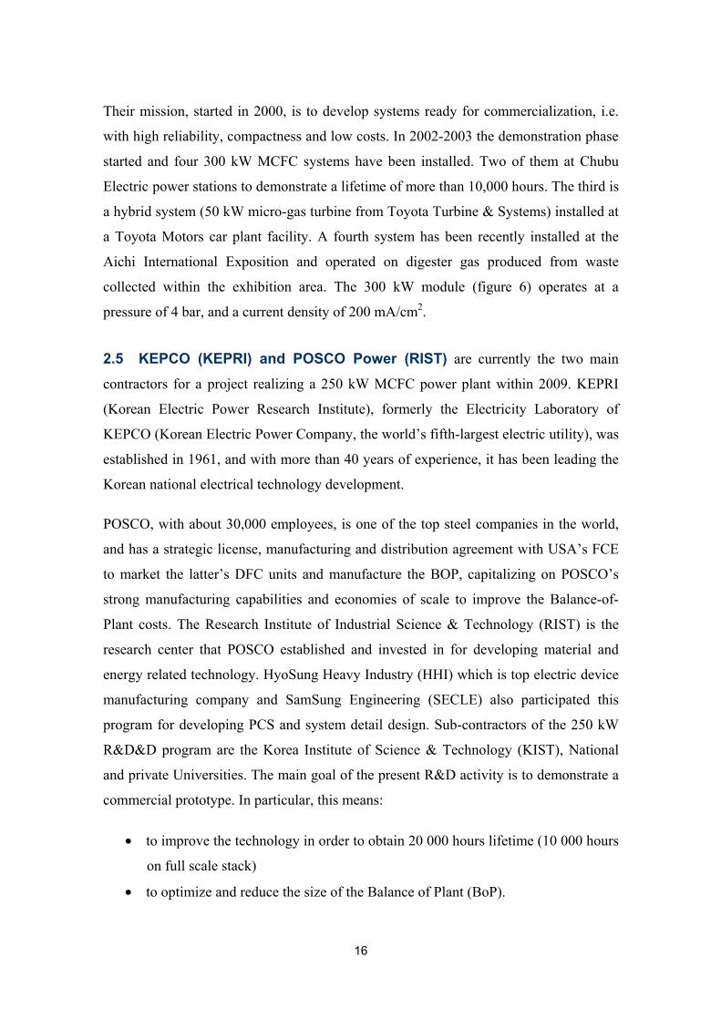
2.5 KEPCO (KEPRI) and POSCO Power (RIST) are currently the two main
contractors for a project realizing a 250 kW MCFC power plant within 2009. KEPRI
(Korean Electric Power Research Institute), formerly the Electricity Laboratory of
KEPCO (Korean Electric Power Company, the world’s fifth-largest electric utility), was
established in 1961, and with more than 40 years of experience, it has been leading the
Korean national electrical technology development.
POSCO, with about 30,000 employees, is one of the top steel companies in the world,
and has a strategic license, manufacturing and distribution agreement with USA’s FCE
to market the latter’s DFC units and manufacture the BOP, capitalizing on POSCO’s
strong manufacturing capabilities and economies of scale to improve the Balance-of-
Plant costs. The Research Institute of Industrial Science & Technology (RIST) is the
research center that POSCO established and invested in for developing material and
energy related technology. HyoSung Heavy Industry (HHI) which is top electric device
manufacturing company and SamSung Engineering (SECLE) also participated this
program for developing PCS and system detail design. Sub-contractors of the 250 kW
R&D&D program are the Korea Institute of Science & Technology (KIST), National
and private Universities. The main goal of the present R&D activity is to demonstrate a
commercial prototype. In particular, this means:
• to improve the technology in order to obtain 20 000 hours lifetime (10 000 hours
on full scale stack)
• to optimize and reduce the size of the Balance of Plant (BoP).

17
Before the construction of 250 kW commercial prototype module units, a 100 kW-class
demonstration plant is being developed as an interim target to verify the domestically
developed MCFC technology. The 100 kW-class demonstration plant was constructed
at the site of Boreyong power plant in Chungnam and was put into operation by the end
of 2005. Recently (2007), a 75kW stack with 7500 cm2 electrode area was installed at
the Boryeong test stand and
operated for evaluation – see
figure 7.
Very recently, a factory was built
in Pohang with a 50 MW/year
capacity; it is scheduled to begin
production in August 2008.
Another important Korean
developer in the area of MCFC
systems is Doosan Heavy
Industries & Construction
(DHI), a world class steam
power plant and desalination plant manufacturing company. They have initiated the
development of 300 kW MCFC models for power generation to be commercialized in
2012. Recently, a 3-year government project to develop a stationary 300 kW Molten
Carbonate Fuel Cell power plant has been launched. DHI, as main contractor of this
project, collaborates with KIER
and Korea Midland Power. The
total budget for this project is
US$ 55.6 million. DHI plans to
build research and production
facilities necessary for cell
component fabrication and stack
manufacturing on the company’s
laboratory area in Daejeon by
early 2008. The first 300 kW
prototype will be released by
Figure 7. 75 kW test stack for the development of the 250 kW system at KEPCO
Figure 8. A 25 kW-class Internal Reforming MCFC stack at DHI

18
late 2010, and the commercial model will be developed by 2012. By virtue of the
established technologies of DHI & Doosan Babcock in power plant system engineering,
various types of the applied products, including a large scale hybrid system for
combined cycle power plants and fuel cell-combined plants with other industrial
systems will be developed by 2015.
DHI is developing all technologies related to MCFC products, such as component
design and fabrication, stack design and manufacturing, and system engineering for
BOP. In 2006, DHI verified its own technology by operating a 25 kW stack – the first of
its kind in Korea. DHI’s stack adopts a unique internal reforming system design.
Various types of BOP are being studied to enhance the operability and to maximize the
system’s efficiency.
2.6 GenCell Corporation, located in Southbury, CT (USA), is a fuel cell developer
and manufacturer with a mission to reduce fuel cell capital costs to first make them
economically viable for the market's early adaptors, and then to further reduce costs to
penetrate the mass market. GenCell started development work
in 1997 and has fourteen patents (issued or pending) to
protect its proprietary fuel cell designs and manufacturing
processes.
GenCell’s MCFC system is positioned in the 40-125 kW
distributed generation market, where there is the largest
number of potential end-users. Commercial scale prototype
stacks are being constructed and operated successfully. The
integral chamber in the MCFC is used as a catalytic indirect internal reformer (patent
pending). Figure 9 is a picture of the 40 kW stack prototype.
Figure 9. 40 kW operational prototype (courtesy of GenCell)

19
3. Achievements and demonstration systems in the world
3.1 Fuel Cell Energy (USA) and CFC Solutions (Germany)
A significant worldwide operational experience has been accumulated with 250 kW
power plants on different fuels and applications.
Based on this experience,
Direct Carbonate Fuel Cells
can be considered ready for
distributed power genera-
tion applications.
However, efforts for further
cost reduction are strongly
needed and are a continuing
part of the companies’
strategy. FCE is also
looking at other possible
applications (hybrid sys-
tems) and markets such as
marine application.
Specifically, the achievements of the two developers sharing the same stack technology,
can be summarized as follows:
o Over 60 systems fielded at customer sites in the US, Japan, and Europe (fig. 10)
o Over 200 million kWh of electricity generated to date at customer sites
o Expanded manufacturing, testing facilities
o Identified and implemented cost reductions, achieved certifications, completed
product standardization
o Completed sub-megawatt field trial program, field follow program in progress,
field units reaching 45-47% efficiency
o Initiated field trial of DFC1500, DFC3000
o DFC-ERG field trial to commence shortly
o Continued development of DFC/T, marine/diesel DFC power plant, and DFC/H2
hydrogen generation plant.
Figure 10. CFC HotModule Installations in Europe (2007, courtesy of CFC Solutions)

20
9,772
8,259
6,254 4,800
3,840
4,300 3.440
20,000
3,250
0
2,000
4,000
6,000
8,000
10,000
12,000
14,000
16,000
18,000
20,000
1996-97 2003 2004 2005 2006 2007 2008
$/kW
Sub-MW 1.2 MW 2.4 MW
Achieved costs for DFC 3000 units (2.4 MW)
It should be noted that, although
FCE and CFC systems were
originally developed for being
operated on natural gas, other
fuels (e.g. coal gas, propane,
diesel, landfill, mine methane,
biogas) were considered as
optional feedstock. In particular,
the use of anaerobic digester gas
(ADG) emerged as an important
commercial fuel during early field trial program and 40% of all installations (including
backlog) use or have used ADG.
FCE has moved its focus from product standardization to further product cost reduction,
developing sustainable markets,
organizational effectiveness, and
continuous product improvement.
Figure 11 shows the cost
reduction from 1996 to 2005 and
the planned cost for 2007, while
figure 12 shows the related
performance improvement, which
includes power density increase.
As capital cost reduction
represents an important factor in
the economical feasibility of a
fuel cell system, O&M costs are
also important factors that need
to be further reduced.
An indication of O&M cost
reduction is provided by figure
13, where the system availability
Figure 11. Cost reduction of FCE products (courtesy of FCE)
Figure 12. Performance improvement (courtesy of FCE)
Figure 13. Availability of FCE systems fleets (courtesy of FCE)

21
is depicted, and by figure 14, reporting the reduction of the fuel cell degradation rate
from 1992 to 2004.
Figure 14. Fuel cell decay rate from 1992 to 2004 (courtesy of FCE)
3.2 Ansaldo Fuel Cells (Italy)
The demonstration program represents a key part of the present phase of development at
AFCo. It mainly aims, through feedback from the field, at extending durability, reduc-
ing costs, simplifying manufacturing processes, improving availability and reliability.
As shown in table 1, the whole program is expected to realize a number of different
plants, both “Series 2TW” and “Series
1ST”. The final goal of the program is to
demonstrate the technology viability for
different fuels and applications, with a to-
tal power of over 4 MW. In addition to
those reported in table 1, preliminary engi-
neering design is on the way for power
plants in the multi-MW class. Figure 15
depicts the hybrid MCFC/Gas turbine
installation at the CESI Ricerca site in Mi-
lan, Italy.
Figure 15. AFCo’s Hybrid MCFC-GT installation in Milan
(courtesy of CESI Ricerche)

22
Table 1. Demonstration program at Ansaldo Fuel Cells (courtesy of AFCo)
Size (Class) Fuel Site Objectives
First of a Kind Series 2TW Natural Gas Guadalix, Spain
Twinstack® and MIR demonstration
WEAO Naval
Application Series 2TW Diesel oil Istanbul,
Turkey Diesel oil fuelled MCFC,
demonstration plant
MCWAP Naval
Application Series 2TW Marine diesel oil On board
Test of onboard MCFC unit, design a multi-MW
system for ship APU
Biomass Application Series 1ST Biomass
gasification Trisaia, Italy Demonstration biomass
gasification/MCFC integrated process
MOCAMI Hybrid Cycle
Series 1ST Natural Gas Milan, Italy MCFC Integration with microturbine
Tecnodemo Series 1ST Natural Gas Alessandria, Italy
MCFC demonstration facility
FISR-BICOCCA Series 2TW Syngas Milan, Italy CO2 separation and management
BICEPS 1 MW class Waste water ADG Terni, Italy Scaling-up with ADG
BICEPS 2 MW class Landfill gas Murcia, Spain
Scaling-up with landfill
AFCo’s main achievements can be summarized as:
o Demonstrated sub-scale single stack system
o Demonstrated 500 kW systems (TWINSTACK®)
o Validated MCFC system and integrated components in hot pressurized vessel
o Validated Integration of stack-microturbine under static and dynamic conditions
(hybrid cycle)
o Validation of control system, power conditioning and grid connection
o 20 000 hrs grid connected (Technodemo)
o Validated the use of alternative fuels (diesel oil, silulated coal gas, simulated
biogas).
23
3.3 Ishikawajima-Harima Heavy Industries (Japan)
IHI MCFC technology was strongly supported by the Japanese New Energy and
Industrial Technology Development Organization (NEDO), which started MCFC
testing activity in 1984, with a 10 kW stack. Later, a 100 kW MCFC was successfully
tested from 1987 to 1992. The results provided the feedback to realize the first Japanese
1 MW power plant, in Kawagoe, which operated for about 5000 hours, producing 2103
MWh.
For the short/mid-term, the goal is to operate a 7 MW MCFC/GT hybrid system, while
the final goal is to replace large-size thermal power plants with MCFC-based ones.
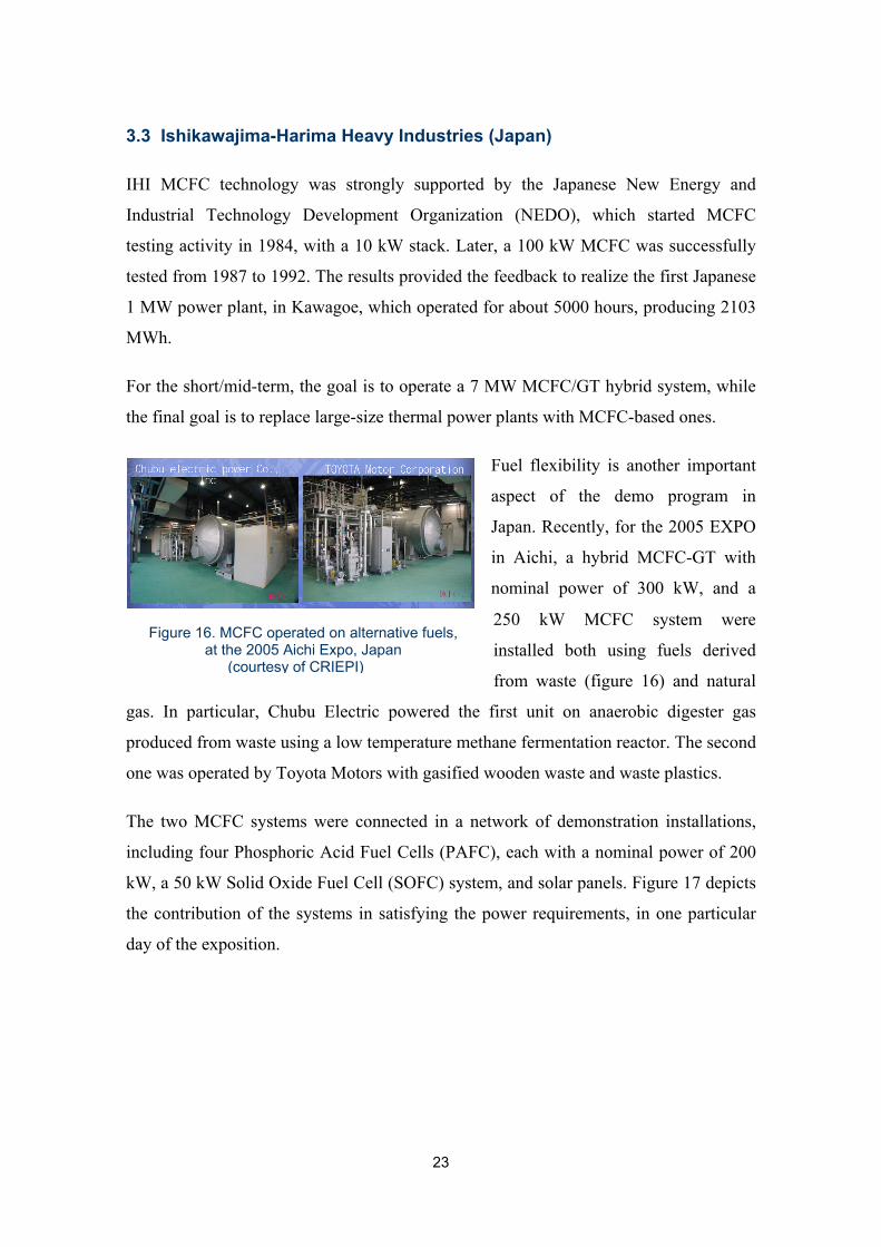
Fuel flexibility is another important
aspect of the demo program in
Japan. Recently, for the 2005 EXPO
in Aichi, a hybrid MCFC-GT with
nominal power of 300 kW, and a
250 kW MCFC system were
installed both using fuels derived
from waste (figure 16) and natural
gas. In particular, Chubu Electric powered the first unit on anaerobic digester gas
produced from waste using a low temperature methane fermentation reactor. The second
one was operated by Toyota Motors with gasified wooden waste and waste plastics.
The two MCFC systems were connected in a network of demonstration installations,
including four Phosphoric Acid Fuel Cells (PAFC), each with a nominal power of 200
kW, a 50 kW Solid Oxide Fuel Cell (SOFC) system, and solar panels. Figure 17 depicts
the contribution of the systems in satisfying the power requirements, in one particular
day of the exposition.
Figure 16. MCFC operated on alternative fuels, at the 2005 Aichi Expo, Japan
(courtesy of CRIEPI)

24
Figure 17. Power demand and power generation during the Aichi Expo (courtesy of CRIEPI)
Main IHI/NEDO plants results include:
• 1 MW, pilot plant realized in Kawagoe and operated for about 5000 hours,
producing 2103 MWh
• Development of commercialization system focused on high reliability,
compactness, and low cost.
• High performance stack realized (250 cells, 1 m2 active area, >1.5 kW/ m2, 350
kW)
• 11 systems installed and operated, for a total of 2.1 MW
• Longest operational time 16 000 hours
• Realization of a 750 kW high performance module as building block for a MW
scale plant (7-8 MW) is in progress
• Realized two 300 kW systems at the Aichi International Exposition, operated on
digester gas produced from waste collected within the exhibition area
• Achieved 51% gross efficiency on Toyota Motor Corporation power plant during Aichi Expo.

25
3.4 KEPCO (KEPRI) and Posco Power (Korea)
The demonstration phase started in 1993, when a 25 kW stack was realized and tested.
This successful phase was followed by tests of stacks of different sizes and system
design and construction. Main plant results in Korea are:
o Realized and operated small-scale stacks (6, 7 and 25 kW, 75 kW)
o Realized and operated a 25 kW stack with high performance and long term
operation, accumulated 4500 hours (ongoing) (pre-test for the 100 kW stack)
o Completed a 100 kW stack and system design
o Almost complete: system construction, stack fabrication, active component
production, BOP fabrication
o 100 kW field tests planned for 2005-2008
o Complete system design for a 250 kW system and prototype of PCS.
POSCO, one of the top steel companies in the world and already a strategic partner of
FuelCell Energy (FCE), has formed a partnership with KEPCO in August 2007 to
develop and jointly market power plants incorporating fuel cell stack modules
manufactured by FCE. POSCO will also provide a 2.4 megawatts (MW) power plant to
KEPCO affiliate Korea South East Power Company (KOSEP) by next year, as a part of
the aggregated 7.8 MW ordered by POSCO this year.
Under the agreement with POSCO announced in February, FuelCell Energy will
continue to manufacture the core fuel cell modules, while POSCO will provide balance
of plant equipment and system integration activities after completion of its
manufacturing plant in 2008.
3.5 GenCell Corporation (USA)
Commercial scale prototypes (40-125 kW) are being built
and operated successfully. GenCell completed operation of a
40 kW unit at the University of Connecticut Campus. The
following figure 18 depicts the system during the
installation.
Figure 18. GenCell’s CHP-40 (courtesy of GenCell)

26
The system operated on natural gas and provided electricity to the Connecticut Global
Fuel Cell Center of the University of Connecticut. GenCell is now starting up its third
40kW MCFC demonstration system.
4. Potential customers and market
The potential market for the current MCFC available products (i.e. in the power range
of 40 kW-2 MW) exceeds the current manufacturing capacity, as reported in [6]. This
fact is mainly due to the high cost and low durability of the systems, which prevents the
technology from penetrating the market adequately. However, despite the cost and
durability issues, at present, there are some niche markets of particular interest for early
adoption of MCFC technology and for facing non-technical issues, such as conformity
to regulation codes and standards. These applications include most of the Distributed
Generation (DG) applications where by-product heat can be recovered in a Combined
Heat and Power (CHP) configuration, including in the CHP definition the integration
with a high temperature fed absorption cooler or a steam injection chiller. The high
temperature outlet gas from the MCFC produces an increased coefficient of power
compared with the presently used thermal coolers.
According to CFC Solutions [7], the revenues for cooling power are significantly higher
than for heat, and the overlapping of heat and cooling power demands over a year
enables a long annual operating time under full load, thus reducing the pay back period
of the system.
CFC and FCE have installed most systems in CHP configuration; in particular hotels,
university campuses and hospitals were found to be ideal candidates for first market
introduction. An example of financial feasibility of a fuel cell-based network operating
in CHP mode was performed by Colella et al. [8] for 200 kW Phosphoric Acid Fuel Cell
(PAFC) systems. The results show the important role of thermal recovery in such
applications.

27
Another point of interest for the early adoption of MCFCs consists in applications
where by-products can be exploited as fuel and replace natural gas. As shown in table 1
and figure 10, there are systems installed or planned to be installed at wastewater
treatment facilities, landfill sites, and breweries. Within the 5th Framework Programme
(FP5), the European Commission funded the EFFECTIVE project, with two main
objectives: 1) to develop gas processing units for upgrading biogas to MCFC quality
requirements and 2) to run MCFC stacks at different locations (Germany, Spain, Austria
and Slovakia) with different types of biogas (from landfill, waste water, agricultural and
co-fermentation facilities). As a result of the project, an MCFC was operated on biogas
for more than 15000 hours, thus demonstrating the technical feasibility of the system,
and in particular of the fuel cell and of the clean-up system. During these fields
operation, the stack achieved 50% of electrical efficiency [9-10].
An estimation of the potential market for fuel cells in the mid term is reported in table 2
[6]. In this study, MCFCs are considered in the range of 250 kW- 2 MW, which reflects
most of the applications available today. As shown in table 2, in 2022 MCFCs could
cover more than 15 GWe. Although the study considers an aggressive market
penetration scenario, it does not take into account possible evolution of the technology
towards multi-MW systems [1-3, 11].
Table 2. Market estimation of fuel cell systems [6]
Potential capacity MW
Technology size & type
Year
5-10 kW
PEM
200 kW
PEM
200-250 kW
SOFC
250-2000 kW
MCFC
2003 7 80 20 52
2007 12 166 118 192
2012 88 1262 893 1.464
2022 848 4.897 5.594 15.029

28
During the 1980s, several studies showed considerable potential of MCFCs in terms of
high efficiency, low emission, and the possibility of separating CO2 for the exploitation
of clean coal.
In most cases, coal-based power plants have a rated power of the order of several
hundreds of MW. Due to the large size of these power plants, no demonstration on real-
scale of such systems has been realized, while the focus for most companies was the
100-500 kW range, based on natural gas. However, in recent years, after many technical
issues have been solved, the option of employing MCFC for coal exploitation has
regenerated much interest.
Ansaldo Fuel Cells is also stressing the interesting role that MCFCs could have in the
short-mid term for CO2 separation. As explained in Annex 1, the MCFC cathode
requires a mixture of oxygen and CO2. The combination of these two gas species
generates CO32- ions, which allows the operation of the fuel cell. As a consequence of
this operation, CO2 is continuously transferred from the cathode to the anode. This
particular feature could be exploited for separating CO2 originating from a traditional
power or thermal power plant (figure 19).
Figure 19. The MCFC as a CO2 separator (courtesy of AFCo)

29
5. Concluding remarks
Molten Carbonate Fuel Cells have been demonstrated at several sites, and in different
sizes. Focus is mostly on the 200 kW-1 MW range, while scale-up to multi-MW power
plants are on the way. Investment cost and durability are still two important issues to be
overcome, in order to ensure a proper market penetration. Therefore, R&D activities are
strongly needed before the technology can be considered mature enough to compete
with traditional energy systems.
However, there are interesting applications where MCFCs already make economical
sense. These include applications where gas is available as a by-product of an industrial
of agricultural process, and/or where Combined Heat and Power (CHP) configurations
can be realized.
Among the number of fuels that MCFCs can employ, hydrogen represents an obvious
option, however, at present there is no demonstration at full scale of a power plant
operated exclusively on hydrogen. The reason for this is the lack of infrastructure, and
the enduring high cost of hydrogen.

30
Annex – MCFC technology explained
Most of the information presented in this section is derived from [27]. In the present
annex, basic information on the technology is reported, in order to allow the reader to
have a better understanding of MCFC technology, and its potential. For a detailed
description of MCFC operating principles, and a comparison with Solid Oxide Fuel
Cells, the reader is referred to [27].
A1. General features
The typical structure of an MCFC is schematically illustrated in figure A1. The
electrolyte is in the liquid and is embedded in a matrix. Ionic transfer inside the
electrolyte is conducted via CO32- ions migrating from the cathode to the anode side.
The chemical reactions that govern the operations are:
−− →++ 2322 2
21 COeOCO (A1)
on the cathode side, while, on the anode: −− ++→+ eCOOHCOH 222
232 (A2)
222 COHOHCO +↔+ (A3)
Expression (A3) is commonly called a shift reaction and converts carbon monoxide and
water into hydrogen. As a consequence of equations (A2)-(A3), water is formed in the
anode side and CO2 is needed in the cathode side. Since the CO2 required for reaction
(A1) is the same formed as consequence of reaction (A2), anodic gas is generally
recycled from the anode to the cathode.
−→++ 2322 2
21 COeOCO
−23CO
eCOOHCOH 222232 ++→+ −
Anodic Gas
Cathodic Gas
e-
e-Electric Load
ANODEANODE
CATHODECATHODE
ELECTROLYTEELECTROLYTE
−→++ 2322 2
21 COeOCO
−23CO
eCOOHCOH 222232 ++→+ −
Anodic Gas
Cathodic Gas
e-
e-Electric Load
ANODEANODE
CATHODECATHODE
ELECTROLYTEELECTROLYTE
Figure A1. Schematic representation of a MCFC

31
The partial pressure of CO2 is not necessarily the same in the cathode and in the anode,
thus the Nernst equation, providing the ideal voltage, is the following:
anode
cathode
COOH
COOH
PPPPP
FRTEE
,22
,222
5.00 ln
2+= (A4)
where E0 is the voltage at standard pressure, R, T, F are, respectively, the universal gas
constant, the temperature and the Faraday constant, while Pi is the partial pressure of the
ith chemical species.
The stable electrolyte/gas interface in the electrodes is based on a capillary pressure
balance [13, 14]. At thermodynamic equilibrium, the diameter of the largest pores that
are flooded, is regulated by the following equation:
e
ee
a
aa
c
cc
DDDϑγϑγϑγ coscoscos
== (A5)
where γ is the interfacial surface tension, ϑ is the contact angle of the electrolyte, and
D is the diameter of the pores. The subscriptions c, a, e refer, respectively, to the
cathode, anode and electrolyte matrix. All the pores with a diameter smaller than D are
filled with the electrolyte, while the pores presenting a larger diameter, remain empty.
The matrix pores present the smallest diameters, and are totally filled with the
electrolyte, while the electrodes are partially filled, according to the pores diameter
distribution.
A2. Materials state of the art
The materials typically used for manufacturing an MCFC are: Nickel-Chromium or
Nickel-Aluminum for the anode, NiO Lithiate for the cathode, Li2CO3/K2CO3 for the
electrolyte, and ⟨-LiAlO2 or ©-LiAlO2 for the matrix ([13, 15, 16]). In order to improve
the cell performance and durability, as well the tolerance of some chemical substances,
present in most of the fuels, alternative materials or particular treatment can be adopted.
As an example, LiNixCo1-xO2 or coated nickel cathode can be considered as alternatives
to the typical NiO Lithiate [17].
One of the most important problems that reduces MCFC longevity is the dissolution of
the cathode in the electrolyte. NiO, in fact reacts with CO2 in the cathode, according to
the following reaction:

32
−+ +↔+ 23
22 CONiCONiO (A6)
Nickel ions migrate through the matrix towards the anode, where they react with the
incoming H2:
22232
2 COOHNiCOHNi ++→++ −+ (A7)
Besides cathode dissolution, another problem related to reactions (A6) and (A7) is that
the resulting metallic nickel precipitates in the matrix, thus leading to short circuiting
across the matrix. As can be noted from expression (A6), a way to reduce cathode
solubility consists in decreasing the CO2 partial pressure. CO2 partial pressure depends
on cathode operating pressure and cathodic gas composition:
cathodeCOcathodeCO XPP,22
⋅= (A8)
(X represents the molar fraction) and so less durability is expected when the stack
operates under pressurized conditions. Several studies have been conducted to assess
NiO solubility, considering different electrolytes and cathodic gas compositions [18-
21].
Various materials are also considered to replace NiO for cathode manufacturing; among
them, LiFeO2, Li2MnO3 and LiCoO2 [22-24] were found to be more stable than NiO,
but their relative performances are noticeably lower. Other possibilities are to reduce the
electrolyte acidity, using particular additives, the performance of the FC is
approximately the same for small percentages of additives such as CaCO3, SrCO3,
BaCO3 [13] or by substituting Li/K electrolyte mixtures with the Li/Na one, with the
aim to find an acceptable compromise between low NiO solubility, ionic conductivity
and low chemical aggressive behavior.
As extensively shown in the present study, one of the main advantages of MCFCs is
that they can operate on a variety of different fuels, such as coal derived fuel, natural
gas, gasified biomass, gasified waste, and landfill gas. While fuel flexibility is a great
advantage for MCFCs, on the other hand, the poisoning effect of some chemical species
contained in these fuels represents a primary issue. Since the most used fuel is currently
natural gas, several investigations have been performed on the effect of sulfur on the
anode and, consequently, on the entire fuel cell performance.
Other harmful substances are NH3, siloxane, chlorine and fluorine. Moreover, since the
anodic gas is generally recycled to the cathode after catalytic combustion, the presence
of NOx in the cathodic gas must also be considered [25].

33
Table A1. Summary of MCFC tolerance to impurities [26]
Contaminants Tolerance limits
Sulphur (H2S) 0.1 - 5 ppm
Nitrogen compounds
NH3
NOx
No effects up to 1%
20 ppm
Halogens (HCl) 0.1-1 ppm
Alkali metals 1-10 ppm
Particulates (> 3 μm) 100 ppm
At the present, the effects of these impurities have been mostly quantified, but not
completely understood at basic level. In table A1 some typical limit values, as well as
the reference, are summarized [26].
A3. Stack and balance of plant design
When realizing an MCFC stack or system, different technical solutions can be adopted.
Each design choice presents its own advantages and disadvantages, and the appropriate
choice is usually the result of an appropriate trade-off analysis. The most significant
differences of MCFC systems regard:
• reforming process (internal or external)
• operating pressure
• manifolding configuration (internal or external).
Table A2 reports the main technical solutions chosen by each MCFC developer.
Table A2. Main design characteristics of MCFC industrial systems
FCE GenCell CFC AFCo IHI POSCO
Manifolding External Anode: int. Cathode: ext.
External External Internal External
Reforming Internal indirect
Internal indirect with ref. chamber in each cell
Internal External External Internal indirect
Operating Pressure
Atm. Atm. Atm. 3.5 bar 1-12 bar Atm.

34
Internal or external reforming process
If the energy source is represented by conventional hydrocarbons, like natural gas,
propane, gasoline etc, a reaction that transforms these into a hydrogen rich gas mixture
is required. There are three main practices that are commonly used:
• Steam Reforming (SR)
• Partial Oxidation (POX)
• Autothermal Reforming (ATR).
The general hydrocarbon conversion reaction can be written in the following form [13]:
( ) ( ) ( ) 222222 76.32/222276.3 NHmpxnnCOOHpxnNOxOHC pmn ++−−+=−−+++ (A9)
The amount of air used in the reaction, denoted with the x symbol, determines the
minimum mole number of the required water, that is 2n-2x-p. In practice, the reaction is
conducted with excess water to ensure the reaction and to avoid carbon deposition.
When no air is used for the fuel conversion (x=0), the process is Steam Reforming (SR),
and is strongly endothermic. By increasing x, the reaction becomes less endothermic
and, according to the selected hydrocarbon, there is a value of x that makes the reaction
thermoneutral. In this case, the conversion process is commonly called Autothermal
Reforming (ATR). When x=1, no water is needed for the reaction and the reaction is
called Partial Oxidation (POX).
A straightforward thermodynamic consideration allows one to estimate which of the
three processes can lead to the highest system efficiency. According to the first
thermodynamic law (energy conservation), and ignoring the thermal losses (adiabatic
reactor), in fact, if heat is provided, (i.e. the reaction is endothermic) the reformed gas
presents an energy content that is higher than the unprocessed fuel. Since in a high
temperature fuel cell system, the heat required for steam reforming is generally recycled
from the fuel cell section, no additional fuel is required for the reforming reaction. This
means that the more endothermic reaction (A9) is, the higher the energy content in the
produced gas is, thus enhancing the system efficiency. When the fuel cell operates at
low temperature, or when the fuel is externally processed and then delivered to the fuel
cell system, the enhanced energy content of the reformed gas is paid by the combustion
of additional fuel and so a system efficiency reduction is possible.

35
In the case of the ATR and POX, instead, no external heat is provided for the reforming
reaction and, therefore, according to the first law, the system efficiency is expected to
be lower than that of the SR.
For the reason explained above, and considering that for MCFC the required heat can be
recovered from the cell itself, if the primary requirement is the realization of highly
efficient systems, SR is chosen as the hydrocarbons processing reaction. For this reason,
all MCFC developers chose SR as the reforming process.
The heat transfer between the fuel cell and the reforming section is substantially
reduced if the reforming process takes place in the anode itself (internal reforming). In
this case, in fact, the heat generated by the electrochemical oxidation of H2 and CO is
directly utilized for the reforming process. It should be stressed, however, that a
complete internal reforming cannot be achieved, therefore a pre-reformer reactor, where
a part of the initial fuel is converted, is needed.
Internal reforming can be conducted in a direct or indirect configuration. As illustrated
in figure A2, in the case of Direct Internal Reforming (DIR), methane is converted into
hydrogen inside the anode section, together with hydrogen oxidation. For Indirect
Internal Reforming (IIR), instead, the reforming section is adjacent to the anode, but
reforming reaction and H2 and CO oxidation do not take place simultaneously.
Figure A2. a) Methane Direct Internal Reforming (DIR);
b) Methane Indirect Internal Reforming (IIR) [27]
C H 4
H 2 C O 2
2224 42 HCOOHCH +↔+
)( )(2 2223
22 COOHCOOH +→+ −−
C A T A L Y S T
H 2O
A N O D E
C H 4
H 2 C O 2
2224 42 HCOOHCH +↔+
)( )(2 2223
22 COOHCOOH +→+ −−
C A T A L Y S T
H 2O
A N O D E
H 2O C H 4
H 2 C O 2
2224 42 HCOOHCH +↔+
)( )(2 2223
22 COOHCOOH +→+ −−
A N O D E
H 2O C H 4
H 2 C O 2
2224 42 HCOOHCH +↔+
)( )(2 2223
22 COOHCOOH +→+ −−
A N O D E
a)
b)
36
This last solution is an intermediate situation between external and internal reforming.
Indirect internal reforming, compared to direct, prevents overcooling effects at the
anode inlet and allows for a high OCV, due to the higher partial pressure of H2. On the
other hand, direct internal allows for a faster and easier reforming process. If methane is
considered, in fact, the following reactions take place simultaneously:
224 3HCOOHCH +→+ (A10)
222 HCOOHCO +↔+ (A11)
OHOH 222 21 →+ (A12)
As a consequence of hydrogen consumption and water production (A12), reaction (A11)
is, in fact, driven to the right.
Pressurized and atmospheric conditions
It is well known that pressurized conditions lead to performance enhancement [13].
Furthermore, pressurized conditions allow for the direct integration of a gas turbine as a
bottoming cycle, which, in turn, is translated into a simple and relatively low cost
system layout.
On the other hand, pressurized conditions lead to several disadvantages. First of all, the
need of a pressurized vessel where the stack is embedded makes the system more
complex and more difficult to control. In particular for MCFC, the pressure difference
between the gas within the fuel cell and the surroundings (i.e. the pressure inside the
vessel) needs to be minimal, in order to avoid fuel cell failure. Secondly, specifically for
MCFC, the partial pressure of CO2 is proportional to cathode dissolution, as explained
in section A2.
Finally, it is important to bear in mind that when pressure increases, backward reaction
of (A10) is favored, thus internal reforming should be limited to fuel cells operating at
atmospheric conditions.
37
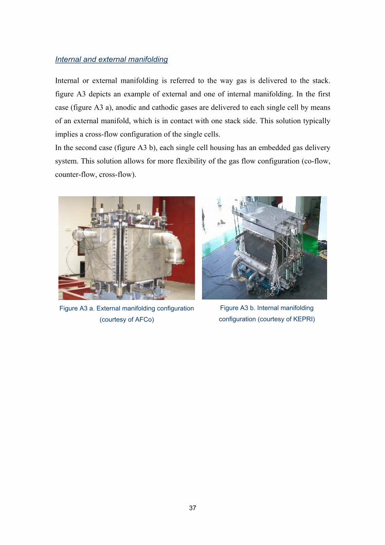
Internal and external manifolding
Internal or external manifolding is referred to the way gas is delivered to the stack.
figure A3 depicts an example of external and one of internal manifolding. In the first
case (figure A3 a), anodic and cathodic gases are delivered to each single cell by means
of an external manifold, which is in contact with one stack side. This solution typically
implies a cross-flow configuration of the single cells.
In the second case (figure A3 b), each single cell housing has an embedded gas delivery
system. This solution allows for more flexibility of the gas flow configuration (co-flow,
counter-flow, cross-flow).
Figure A3 a. External manifolding configuration
(courtesy of AFCo)
Figure A3 b. Internal manifolding
configuration (courtesy of KEPRI)

38
References
[1] Marcenaro B. and Federici F., 2005. MCFC Fuel Cells Development at Ansaldo Fuel Cells.
Proceedings of the. International Hydrogen Energy Congress and Exhibition (ICHET 2005), 13-
15 July, 2005, Istanbul, Turkey.
[2] Ghezel-Ayagh H., Walzak J., Patel D., Daly J., Maru H.. Sanderson R. and Livingood W.,
2005. State of direct fuel cell/turbine systems development. Journal of Power Sources, Volume
152, pp. 219-225
[3] Tooi M., 2005. Development of Molten Carbonate Fuel Cell in Japan. Proceedings of 2005
Fuel Cell Seminar, November 14-18, 2005, Plam Spring, CA.
[4] Cropper M., 2003 “Fuel Cell Market Survey, large Stationary Applications” Survey report
downloadable from www.fuelcelltoday.com
[5] Adamson, K.-A., 2007. Fuel Cell Today Market Survey: Large Stationary Applications
2007. Survey report downloadable from www.fuelcelltoday.com
[6] Anna Monis Shipley, R. Neal Elliott, 2004. “Stationary fuel cells: future promise, current
hype” ACEEE Report number IE041
[7] Personal communication with G. Huppmann, CFC Solutions.
[8] Colella, W., Niemoth, C., Lim, C., Hein, A., “Evaluation of the Financial and Environmental
Feasibility of a Network of Distributed 200 kWe Cogenerative Fuel Cell Systems on the
Stanford University Campus,” Fuel Cells – From Fundamentals to Systems, 1, 148-166, Feb.
2005.
[9] Trogisch S., Hoffmann J. and Daza Bertrand L., 2005. Operation of molten carbonate fuel
cells with different biogas sources: A challenging approach for field trials Journal of Power
Sources, Volume 145, Issue 2, pp. 632-638.
[10] Trogish, S., Baaske, W. E. (eds), 2004. Biogas Powered Fuel Cells. Trauner Verlag, Linz,
Austria.
[11] Farooque M. and Maru H.C., 2006. Carbonate fuel cells: Milliwatts to megawatts. Journal
of Power Sources 160, pp. 827–834.
[12] Bove R., Lunghi P., Lutazi A. and Sammes N. M. (2004) Biogas as fuel for a fuel cell
system: investigation and first experimental results for a molten carbonate fuel cell. Accepted
for publication on ASME Fuel Cell Science and Technology.
[13] Hirchenhofer J.H. et al. (2002) Fuel cell handbook, sixth edition, US Department of
Energy.
[14] Larinne J. and Dicks A. (2000) Fuel Cell Systems Explained. Wiley and Sons, UK.
[15] Carrette L., Friedrich K. A. and Stimming U. (2001) Fuel Cells-fundamentals and
applications. Fuel Cells from Fundamental to Systems 1, 1, 5-39.
[16] Lunghi P. and Bove R. (2003) Life Cycle Assessment of a Molten Carbonate Fuel Cell
Stack. Fuel Cells from Fundamental to Systems 3, 4, 224-230.

39
[17] Colonmer H., Ganesan P. and Subramanian (2002) Optimization of the cathode long-term stability in molten carbonate fuel cells: experimental study and mathematical modeling. Final Report submitted to US DOE. DOE Award number DE-AC26-99FT40714. [18] M. S. and Selman J. R. (1998) Dissolution of partially immersed nickel during in situ oxidation in molten carbonate: cycling, stripping and square wave voltammetry measurements. Journal of Electroanalytical Chemistry 457, 89-97. [19] Peelen W. H., Hemmes K. and de Wit J. H. (1997) Diffusion constants and solubility values of CO2+ and Ni2+ in Li/Na and Li/K carbonate melts. Electrochemical Acta 42, 15, 2389-2397. [20] Ota K., Takeishi Y., Shibata S., Yoshitake H., Kamiya N., Yamazaki N. (1995) Solubility of cobalt oxide in molten carbonate. Journal of Electrochemical Society 142, 10, 3322. [21] Baumgartner C. E. (1984) NiO solubility in molten Li/K carbonate under molten carbonate fuel cell cathode environment. Journal of Electrochemical Society 131, 8, 1850. [22] Lundblad A., Schwartz S. and Bergman B. (2000) Effects of sintering procedures in development of LiCoO2-cathodes for the molten carbonate fuel cell. Journal of Power Sources 90, 224-230. [23] Giorgi L., Carewska M., Patriarca M., Scaccia S., Simonetti E. and Di Bartolomeo A. (1994) Development and characterization of novel cathode materials for molten carbonate fuel cell. Journal of Power Sources 49, 1-3, 227-243. [24] Veldhuis J. B.J., Eckes F.C. and Plomp L. (1992) The dissolution properties of LiCoO2 in molten 62:38 mole percent Li:K carbonate. Journal of Electrochemical Society 139, 1, L6. [25] Kawase M., Mugikura Y., Watanabe T., Hiraga Y.Hujihara T (2002) Effects of NH3 and NOx on the performance of MCFCs. Journal Power Sources 104, 265-271. [26] Desideri U., Lunghi P. and Burzacca R. (2002) State of the art about the effects of impurities on MCFCs and pointing out of additional research for alternative fuel utilization. Proceedings of 1st International Conference of Fuel Cell Science, Engineering and Technology, April 21-23, 2003, Rochester, NY, USA. [27] Moreno A., Bove R., Lunghi P. and Sammes N. M., 2005. High temperature fuel cells. Chapter 18 of the book: “Biofuels for Fuel Cells: Biomass Fermentation Towards Usage in Fuel Cells”, IWA Publishing, London, UK. Edited by P. Liens, P. Westermann, M. Haberbauer and A. Moreno. [28] DoD (2004) Department of Defense/ Fuel cell/ERDC-CERL Programs, website: http://www.dodfuelcell.com [29] DoE (1998) Landfill gas clean up for molten carbonate fuel power generation. US Department of Energy and Electric Power Research Institute, Final Report CRADAMC95-031. [30] EPA (2004) Database of Landfills and Energy Projects, downloadable on http://www.epa.gov/lmop/index.htm

Published by ENEA
Communication Unit
Lungotevere Thaon di Revel, 76 – 00196 Rome
www.enea.it
Editing: Giuliano Ghisu
Printed by Primaprint (Viterbo) - April 2008