Embed Size (px)
DESCRIPTION
UNSW CVEN1300
Citation preview
StructuralStructural AnalysisAnalysis
TRUSSESTRUSSESTRUSSES
M th d fM th d fMethod of Method of JointsJointsJointsJoints
Tutorial Problems:Tutorial Problems:Tutorial Problems:Tutorial Problems:
Chapter 6Chapter 6Chapter 6Chapter 6

TRUSSES – METHOD OF JOINTSTRUSSES METHOD OF JOINTS
Today’s Objectives:
Students will be able to:
a) Define a simple truss.
b) Determine the forces in members of ain members of a simple truss.
c) Identify zero-forcec) Identify zero-force members.

APPLICATIONSAPPLICATIONS
Trusses are commonly used to support a roof.
F i dFor a given truss geometry and load, how can we determine the forces in the truss members andforces in the truss members and select their sizes?
A more challenging question is that for a given load, how can we g ,design the trusses’ geometry to minimize cost?
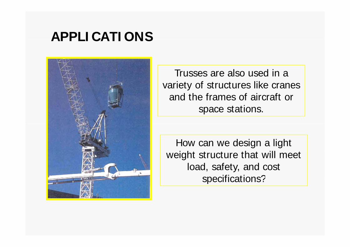
APPLICATIONSAPPLICATIONS
Trusses are also used in a variety of structures like cranes
and the frames of aircraft orand the frames of aircraft or space stations.
How can we design a light i ht t t th t ill tweight structure that will meet
load, safety, and cost specifications?specifications?
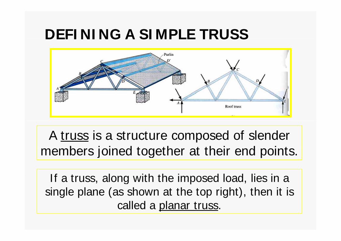
DEFINING A SIMPLE TRUSSDEFINING A SIMPLE TRUSS
A truss is a structure composed of slender b j i d t th t th i d i tmembers joined together at their end points.
If t l ith th i d l d li iIf a truss, along with the imposed load, lies in a single plane (as shown at the top right), then it is
ll d l tcalled a planar truss.

DEFINING A SIMPLE TRUSSDEFINING A SIMPLE TRUSSA simple truss is a planar truss whichplanar truss which
begins with a triangular element and can beelement and can be expanded by adding two members and atwo members and a
joint. For these trusses, the number ofthe number of
members (M) and the number of joints (J) arenumber of joints (J) are related by the equation
M = 2 J – 3.

ANALYSIS and DESIGN ASSUMPTIONS
When designing both the member and the joints of a fi i i d i h f i htruss, first it is necessary to determine the forces in each
truss member. This is called the force analysis of a truss. When doing this two assumptions are made:When doing this, two assumptions are made:
1 All loads are applied at the joints The weight of the1. All loads are applied at the joints. The weight of the truss members is often neglected as the weight is usually small as compared to the forces supported by the members.
2 Th b j i d t th b th i Thi2. The members are joined together by smooth pins. This assumption is satisfied in most practical cases where the joints are formed by bolting or welding.j y g g
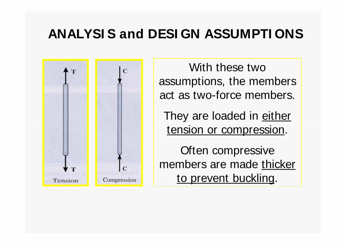
ANALYSIS and DESIGN ASSUMPTIONS
With these twoWith these two assumptions, the members act as two-force membersact as two-force members.
They are loaded in either tension or compression.
Often compressiveOften compressive members are made thicker
to prevent bucklingto prevent buckling.

THE METHOD OF JOINTS
In this method of solving for the forces in truss members theIn this method of solving for the forces in truss members, the equilibrium of a joint (pin) is considered. All forces acting at
the joint are shown in a FBD.
This includes all external forces (including support reactions) as well as the forces acting in the members. Equations of
equilibrium (∑ FX= 0 and ∑ FY = 0) are used to solve for the unknown forces acting at the joints.

QUIZQUIZ
1. One of the assumptions used when analyzing a simple truss is that the members are joined together by __________.
A) welding B) bolting C) riveting
D) smooth pins E) super glueD) smooth pins E) super glue
2 I th th d f j i t t i ll ti2. In the method of joints, typically _________ equations of equilibrium are applied at every joint.
A) two B) three
C) four D) six
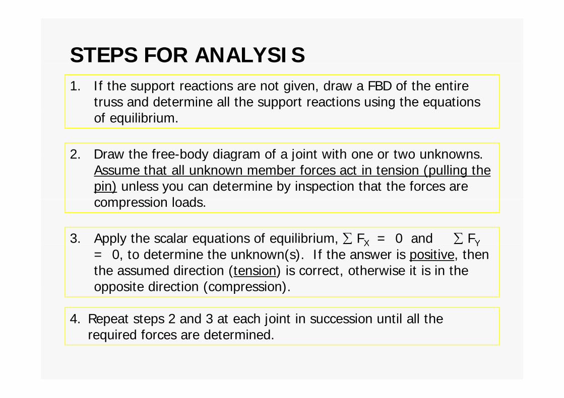
STEPS FOR ANALYSIS1. If the support reactions are not given, draw a FBD of the entire
truss and determine all the support reactions using the equations pp g qof equilibrium.
2 Draw the free-body diagram of a joint with one or two unknowns2. Draw the free-body diagram of a joint with one or two unknowns. Assume that all unknown member forces act in tension (pulling the pin) unless you can determine by inspection that the forces are
i l dcompression loads.
3. Apply the scalar equations of equilibrium, ∑ FX = 0 and ∑ FYpp y q q , X Y= 0, to determine the unknown(s). If the answer is positive, then the assumed direction (tension) is correct, otherwise it is in the opposite direction (compression).opposite direction (compression).
4. Repeat steps 2 and 3 at each joint in succession until all the required forces are determinedrequired forces are determined.

ZERO-FORCE MEMBERSZERO FORCE MEMBERSIf a joint has only two non-colinear members and there is no externalmembers and there is no external load or support reaction at that joint, then those two members are zero-f b I thi lforce members. In this example members DE, CD, AF, and AB are zero force members.
You can easily prove these results by applying the equations of equilibrium to joints D and A.
Zero-force members can be removed (as shown in the figure)
h l hwhen analyzing the truss.

ZERO-FORCE MEMBERSIf three members form a truss joint for which two of the members are collinear
ZERO FORCE MEMBERS
which two of the members are collinear and there is no external load or reaction at that joint, then the third non-collinear j ,member is a zero force member.
Again, this can easily be proven. One g , y pcan also remove the zero-force member, as shown, on the left, for analysing the truss furthertruss further.
Please note that zero-force members are used to increase stability and rigidity of the truss, and to provide support for various different loading conditions.various different loading conditions.

QUIZQUIZP
1. Truss ABC is changed by decreasing its height from H to 0.9 H. Width W and load P k t th Whi h f th
H
A
BP are kept the same. Which one of the following statements is true for the revised truss as compared to the original truss?
B C
Wp g
A) Force in all its members have decreased.
W
B) Force in all its members have increased.
C) Force in all its members have remainedC) Force in all its members have remained the same.
D) None of the aboveD) None of the above.

QUIZF F
F
QUIZ
F
2. For this truss, determine the number of zero-force members.
A) 0 B) 1 C) 2) ) )
D) 3 E) 4

SOLUTIONSOLUTION FBD of pin A
Analyzing pin A:y
AFAC 240 kN
∑FY ↑+ = 0
= – 100 – (5 / 13) FAB F
x13 5
12 100 (5 / 13) FAB
F = 260 kN (C)
FAB12
100 kN
FAB = – 260 kN (C)
∑ F + = 240 F (12 / 13) ( 260) = 0∑ FX+ = 240 – FAC – (12 / 13) (– 260) = 0
FAC = 480 kN (T)FAC 480 kN (T)

QUIZQUIZ
1 Using this FBD you find thatFBC
1. Using this FBD, you find that
FBC = – 500 N. Member BC must be in . FB__________.
A) tension B) compression
C) Can not be determined
FBDB
BC) Can not be determined
2. For the same magnitude of force to be carried, truss members in
BY
g ,compression are generally made _______ as compared to members in tension.
A) hi kA) thicker
B) thinner
C) the same size

TRUSSES –TRUSSES METHOD OFMETHOD OF SECTIONSSECTIONSSECTIONS

TRUSSES–THE METHOD OF SECTIONS
Today’s Objectives:Objectives:
Students will be able to determine forces in truss members using the method ofthe method of sections.

QUIZ1. In the method of sections, generally a “cut” passes through
QUIZ
no more than _____ members in which the forces are unknown.
A) 1 B) 2
C) 3 D) 4
2. If a simple truss member carries a tensile force of T along its length, then the internal force in the member is ______ .A) tensile with magnitude of T/2 B) compressive with magnitude of T/2B) compressive with magnitude of T/2C) compressive with magnitude of T D) tensile with magnitude of TD) tensile with magnitude of T

APPLICATIONSAPPLICATIONS
Long trusses are often used to construct bridges.
The method of joints requires that many joints be analyzed before we can determine the
forces in the middle part of the trusstruss.
Is there another method to determine these forces
directly?

THE METHOD OF SECTIONSTHE METHOD OF SECTIONS

THE METHOD OF SECTIONSTHE METHOD OF SECTIONS
In the method of sections, a truss is divided into two parts by taking an imaginary “cut” (shown here as a-a)
through the truss.
Since truss members are subjected to only tensile or compressive forces along their length, the internal forcescompressive forces along their length, the internal forces
at the cut member will also be either tensile or compressive with the same magnitude.
This result is based on the equilibrium principle and Newton’s third law.

STEPS FOR ANALYSISSTEPS FOR ANALYSIS

STEPS FOR ANALYSISSTEPS FOR ANALYSIS1. Decide how you need to “cut” the truss. This is based
on:on: a) where you need to determine forces, and,
b) h th t t l b f k d tb) where the total number of unknowns does not exceed three (in general).
2. Decide which side of the cut truss will be easier to work with (minimize the number of reactions you havework with (minimize the number of reactions you have to find).
3. If required, determine the necessary support reactions by drawing the FBD of the entire truss and applying the E fEEofE.

4 Draw the FBD of the selected part of the cut truss 4. Draw the FBD of the selected part of the cut truss.
We need to indicate the unknown forces at the cut members.
Initially we assume all the members are in tension, as we did when using the method of joints. when using the method of joints.
Upon solving, if the answer is positive, the member is in tension as per our assumption.
If the answer is negative the member must be in If the answer is negative, the member must be in compression.
(Pl h l f b i h (Please note that you can also assume forces to be either tension or compression by inspection as was done in the figures above )figures above.)

5. Apply the equations of equilibrium 5. Apply the equations of equilibrium (EofE) to the selected cut section of th t t l f th k the truss to solve for the unknown member forces.
Please note that in most cases it is possible to write one equation to solve for one unknown directlysolve for one unknown directly.

EXAMPLEEXAMPLE
Given: Loads as shown on the roof truss.
Find: The force in members DE DL and MLDE, DL, and ML.
PlPlan:
) T k t th h th b DE DL d MLa) Take a cut through the members DE, DL, and ML.
b) Work with the left part of the cut section. Why?
c) Determine the support reaction at A. What are they?
d) Apply the EofE to find the forces in DE DL and MLd) Apply the EofE to find the forces in DE, DL, and ML.

EXAMPLEEXAMPLE

EXAMPLEEXAMPLE

QUIZQUIZ
1.Can you determine the force in member ED by making the cut atmaking the cut at section a-a? Explain your answer.y
A) No, there are 4 unknowns.unknowns.
B) Yes, using Σ MD = 0 .
C) Yes, using Σ ME = 0 .
D) Yes, using Σ MB = 0 .) , g B
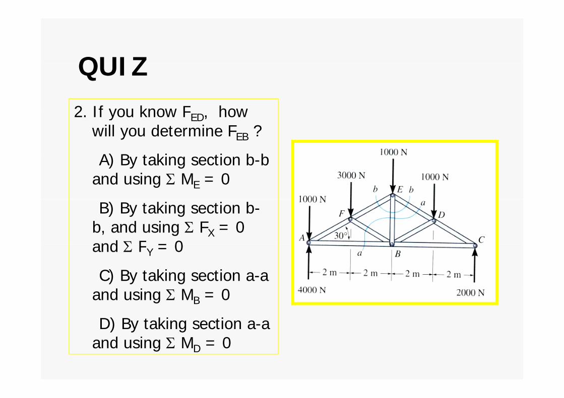
QUIZQUIZ2 If you know F how2. If you know FED, how
will you determine FEB ?
A) B ki i b bA) By taking section b-b and using Σ ME = 0
B) By taking section b-b, and using Σ FX = 0 and Σ F 0and Σ FY = 0
C) By taking section a-a d i M 0and using Σ MB = 0
D) By taking section a-a and using Σ MD = 0

GROUP PROBLEM SOLVING
Given: Loading on the truss as hshown.
Find: The force in members BC, BE, and EF.
Plan:
a) Take a cut through the members BC, BE, and EF.
b) Analyze the top section (no support reactions!).
c) Draw the FBD of the top section.
d) Apply the equations of equilibrium such that every equation yields answer to one unknown.
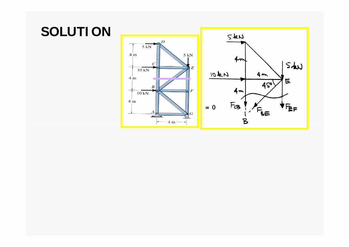
SOLUTION

QUIZQUIZ1. As shown, a cut is made ,
through members GH, BG and BC to determine the forces in them Which sectionforces in them. Which section will you choose for analysis and why?
A) Right, fewer calculations.
B) Left fewer calculationsB) Left, fewer calculations.
C) Either right or left, same amount of workamount of work.
D) None of the above, too many unknownsmany unknowns.

QUIZQUIZ
2. When determining the force in member HG in the
i ti hi hprevious question, which one equation of equilibrium is best to use?best to use?
A) Σ MH = 0
B) Σ MG = 0
C) Σ MB = 0) B
D) Σ MC = 0

Exam 2006Exam 2006
• Determine the force in each member of the truss h i h f ll i fi I di h h hshown in the following figure. Indicate whether the
members are in tension or compression. Assume each member is pin-connectedeach member is pin-connected.

Exam 2007Exam 2007
• Determine the forces in members BC, HG, CD and GF f h b id h i h fi I diof the bridge truss shown in the figure. Indicate
whether the members are in tension or compression. Assume each member is pin-connectedAssume each member is pin-connected.
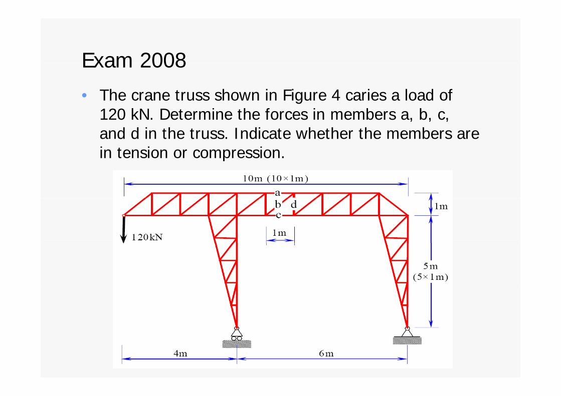
Exam 2008Exam 2008
• The crane truss shown in Figure 4 caries a load of 120 kN D i h f i b b120 kN. Determine the forces in members a, b, c, and d in the truss. Indicate whether the members are in tension or compressionin tension or compression.