Embed Size (px)
Citation preview

Welcome to
and state of the art technologyfor electric power transmission

Content – State-of-the-art technology! Introduction to STRI! What is reliability centered design ?! New substation design with composite insulation! Software to optimize & compare availability for
substations! New transmission line design with composite insulation! Software to optimize & compare availability for
transmission line! What is reliability centered maintenance? ! New possibilities with SOLA on line diagnostics! New possibilities with IEC 61850 on line

Compact 400 kV transmission linewith polymer insulators & arrestors

Compact 400 kV transmission linewith half the size and EM radiation

Transition towers for 220 and 400 kVfrom line to cable (s) with polymer


Content – State-of-the-art technology! Introduction to STRI! What is reliability centered design ?! New substation design with composite insulation! Software to optimize & compare availability for
substations! New transmission line design with composite insulation! Software to optimize & compare availability for
transmission line! What is reliability centered maintenance? ! New possibilities with SOLA on line diagnostics! New possibilities with IEC 61850 on line

Reliability/Availability Insulation EM Field Dynamic load
Software for optimizing the design of transmission lines

Statistical methods in Line Performance Estimator (LPE)
" Service voltage (pollution and ice)! STRI’s statistical method
" Lightning overvoltages! Back flashover rate (CIGRÉ methods)! Shielding failure rate (CIGRÉ methods)
" Switching overvoltages! Switching surge flashover rate (IEC 60071)

Statistical approach: theoretical basis
1. Pollution stress at site: probability density function f(γ)
2. Probability for flashover at maximum operating voltage: cumulative distribution function P(γ)
3. Multiplication of the f and P and the area under this curve defines the risk for flashover
Stress f(γ) Strength P(γ)
Risk for flashover
Pollution severity(γ)
Stre
ss: d
ensi
ty o
f occ
urre
nce
Stre
ngth
: pro
babi
lity
for f
lash
over
)()( γγ Pf •
Stress f(γ) Strength P(γ)
Risk for flashover
Pollution severity(γ)
Stre
ss: d
ensi
ty o
f occ
urre
nce
Stre
ngth
: pro
babi
lity
for f
lash
over
)()( γγ Pf •

,
Verification for UHV 1150 kV (Russia)
! Field data collected from 40 test stations:! Surface conductivity! NSDD! Flashover voltage of
naturally polluted insulators

Verification by service records -Location of OHL with known service records-

Pollution: LPE vs. service recordsFailure rate per year
Source Max.
voltage [kV]
Lines recorded in service
calculated in LPE
420 1 0-0,1 0,2 420 2 0 0,2 420 3 0 0,01
Statnett (Norway)
300 4 0-0,2 0,1 400 1 0,6 1,0 400 2 1,0 0,5 400 3 0,2 0,5
ESKOM (South Africa) 400 4 0 0,02
126 1 0,4 0,4 NIIPT (Russia) 126 2 1,4 3,0

Lightning: LPE vs. service recordsCountry Line System
voltage Recorded
failure rate in service
Calculated failure rate in
LPE
kV 1/100 km/yr 1/100 km/yr
1 420 0,23 0,10 2 420 0,29 0,38 3 420 0,33 0,09
Norw ay
4 300 0,13 0,36 1 420 0,07 0,04 2 420 0,14 0,14 Sweden 3 420 1,1 0,75
Russia 1 115 1,35* 1,4* 1 400 0 0,08
South Africa 2 400 0,8 0,35
* Double circuit line
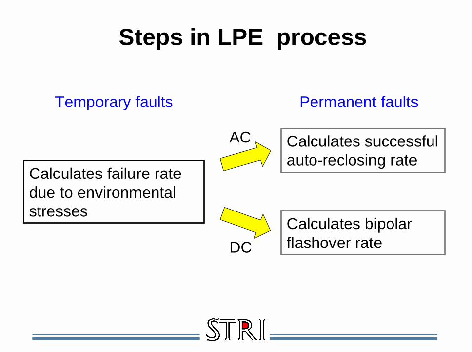
Steps in LPE process
Calculates failure rate due to environmental stresses
Calculates successful auto-reclosing rate
Calculates bipolar flashover rate
AC
DC
Temporary faults Permanent faults

Ice
Pollution
Lightning
High altitude
Line sections in LPE

LPE for HVAC Lines
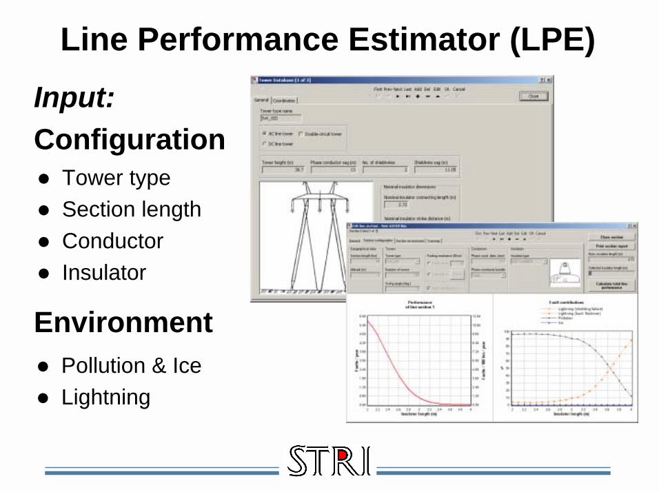
Line Performance Estimator (LPE)Input:Configuration
Environment
! Tower type! Section length! Conductor! Insulator
! Pollution & Ice! Lightning

Line Performance Estimator (LPE)
! Pollution & Ice! Lightning
! Successful autoreclosing rate
OutputFailure rate forline due to:
Availability

Select type of tower from libraryOr create your new

Select type of isolator from libraryOr create your new

Select environment and calculate fault frequency as function of insulator length

Next step: Calculate fault frequency for the whole line

Calculate successful autoreclosingwith and without surge arrester

LPE for HVDC Lines

Configure your HVDC tower

Enter insulator data
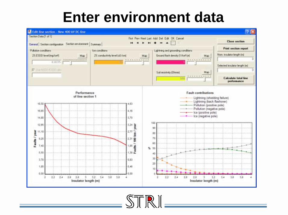
Enter environment data

Read the result and modify input data for sensitivity analysis

Input data through testing – Example:800 kV DC pollution testing of V-string

Compare UHVAC and UHVDC 800 kV

Content – State-of-the-art technology! Introduction to STRI! What is reliability centered design ?! New substation design with composite insulation! Software to optimize & compare availability for
substations! New transmission line design with composite insulation! Software to optimize & compare availability for
transmission line! What is reliability centered maintenance?! New possibilities with SOLA on line diagnostics! New possibilities with IEC 61850 on line

What is Reliability Centered Maintenance?
! Optimum maintenance techniques with on-line monitoring and on-site measurement
! Internet based diagnostics! Including temperature, PD, pollution and
motion analysis! Statistics, trends and fingerprints
! CBM planning! Condition Based Maintenance
! RCM planning! Reliability Centered Maintenance
based on risk, consequence & condition
! Maintenance work with voltage

200 - 800 kV
Industry
Generation
Transmission
Distribution
6 - 200 kV
Stress and ageing of the power system
AGEING
ABNORMALOPERATION
FAULT
REMAINING LIFE TIME FULLASSETVALUE
STRESSMARGIN

! Current withstand! All equipment is designed for a rated continuous load
current and a short circuit withstand limit! Overload with increased temperature and short circuit
with increase mechanical stresses in combination with material ageing could result in accelerated ageing and a failure
! Voltage withstand! All equipment is designed for a rated continuous
operating voltage and LI/SI voltage withstand! Overvoltage in combination with pollution and material
ageing could result in accelerated ageing and a failure! Supervision
! Above conditions has to be supervised
Stress and ageing of the power system

Installed Power
0
500
1000
1500
2000
2500
3000
3500
4000
Y 1950 Y 1960 Y 1970 Y 1980 Y 1990 Y 2000
Year
GW GW
30 GW/year 70 -100 GW/year 70-100 GW year
Total potential = 70 -100 GW new + 70 - 100 GW retro
Life extention or replacement
2% = 70 GW/year
2000 GW
Replace
Retrofit
New
Install Base
Installed eq. 110 -800 kV WORLD TOTALSubtotal GIS & Modules 35000Subtotal LTB 350000Subtotal DTB 90000Subtotal GCB 6000SUB TOTAL CB 481000Current Transformers 1000000Voltage Transformers 500000

STRI Diagnostics Example:! Generators & Large motors:
! Protection: Limiters, O/C, EF, Differential, Z<, Under Excitation, O/V, U/V, Frequency, Negative sequence, P<, Pr
! Evaluate different methods for diagnostics! PD, Temperature, Vibration
! Propose optimum method
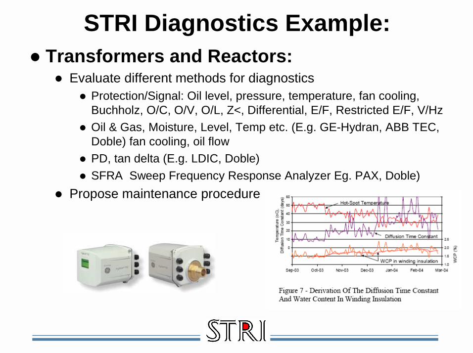
! Transformers and Reactors:! Evaluate different methods for diagnostics
! Protection/Signal: Oil level, pressure, temperature, fan cooling,Buchholz, O/C, O/V, O/L, Z<, Differential, E/F, Restricted E/F, V/Hz
! Oil & Gas, Moisture, Level, Temp etc. (E.g. GE-Hydran, ABB TEC,Doble) fan cooling, oil flow
! PD, tan delta (E.g. LDIC, Doble)! SFRA Sweep Frequency Response Analyzer Eg. PAX, Doble)
! Propose maintenance procedure
STRI Diagnostics Example:
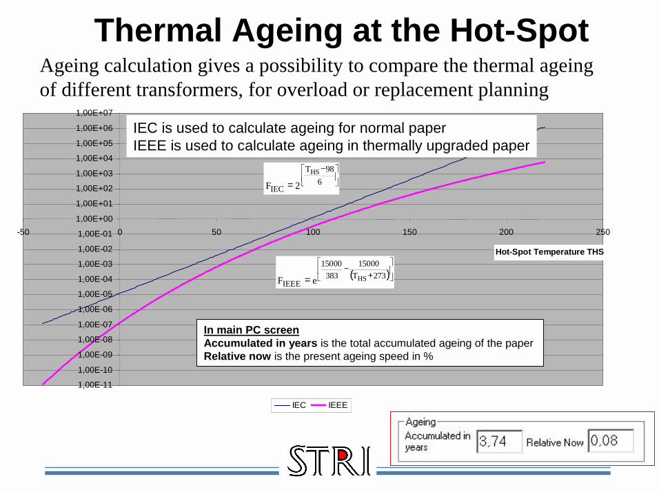
Thermal Ageing at the Hot-Spot
1,00E-11
1,00E-10
1,00E-09
1,00E-08
1,00E-07
1,00E-06
1,00E-05
1,00E-04
1,00E-03
1,00E-02
1,00E-01
1,00E+00
1,00E+01
1,00E+02
1,00E+03
1,00E+04
1,00E+05
1,00E+06
1,00E+07
-50 0 50 100 150 200 250
Hot-Spot Temperature THS
IEC IEEE
−
= 698T
IEC
HS
2F
( )
+
−= 273T
15000383
15000
IEEEHSeF
IEC is used to calculate ageing for normal paperIEEE is used to calculate ageing in thermally upgraded paper
In main PC screenAccumulated in years is the total accumulated ageing of the paperRelative now is the present ageing speed in %
Ageing calculation gives a possibility to compare the thermal ageing of different transformers, for overload or replacement planning

! Moisture!GE Hydran!PAX Diagnostics IDAX 206!DOBLE IDD Moisture in oil!KELMAN TRANSFIX
! Gas detection!Buchholz!GE Hydran!DOBLE IDD DGA!KELMAN TRANSFIX
Example of oil and gas monitoringfor transformers
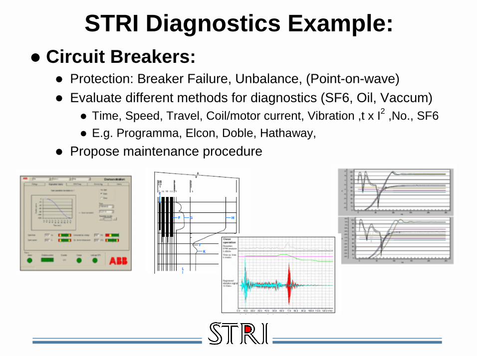
STRI Diagnostics Example:! Circuit Breakers:
! Protection: Breaker Failure, Unbalance, (Point-on-wave)! Evaluate different methods for diagnostics (SF6, Oil, Vaccum)
! Time, Speed, Travel, Coil/motor current, Vibration ,t x I2 ,No., SF6! E.g. Programma, Elcon, Doble, Hathaway,
! Propose maintenance procedure

STRI Diagnostics Example:! Cables:
! Protection: O/C, EF, Pilot wire, Current Diff.! Evaluate different methods for diagnostics
! IR, Temperature! PD
! • Inductive loop! • Capacative sensor! • Inductive UHF-sensor! • Acoustical sensor
! Propose optimum method

STRI Diagnostics Example:! Line joints:
! Protection: Zero & negative sequence! Evaluate different methods for diagnostics
! IR, Temp, Resistance! Propose maintenance procedure
! Disconnectors:! Protection: Zero & negative sequence, busbar! Evaluate different methods for diagnostics
! IR, Temp, Resistance! Propose maintenance procedure
! Insulators:! Protection: Eartfault & shortcircuit protection! Evaluate different methods for diagnostics
! IR, UV, leakage current/pollution monitoring! Propose maintenance procedure

To be monitored and/or tested:# Line ending and joints (Resistance/Temp/IR)# Conductors (Temperature)# Towers (Corrosion)# Cable ending and joints (PD, Temp/IR)# Arresters (Leakage current)# Earthing switch (Resistance to ground)# Voltage transformer (Oil analysis)# Current transformer (Oil analysis)# Disconnector (Resistance/Temp/IR)# Circuit Breaker (SF6, time, resistance, vibration)# Insulators (Temp/IR/UV/Leakage current)# Power Transformer (PD, Oil and gas analysis)# Generator (PD, temperature, vibration)
200 - 800 kV
Example of Condition Monitoring
Industry
Generation
Transmission
Distribution
6 - 200 kV

Content – State-of-the-art technology! Introduction to STRI! What is reliability centered design ?! New substation design with composite insulation! Software to optimize & compare availability for
substations! New transmission line design with composite insulation! Software to optimize & compare availability for
transmission line! What is reliability centered maintenance? ! New possibilities with SOLA on line diagnostics! New possibilities with IEC 61850 on line

Introducing SOLASTRI On Line Analyser
On Line On Line Diagnostics Diagnostics On On Site DiagnosticsSite Diagnostics
CBM & RCMCBM & RCM
My SQL My SQL databasedatabase

SOLA SOLA –– STRI On Line AnalyserSTRI On Line Analyser
SOLA for lines and substations

SOLA SOLA –– STRI On Line AnalyserSTRI On Line Analyser
SOLA for lines and substations

SOLA for lines and substations

SOLA for lines and substations

Grid Owner
InspectorPurchase Order
Report
Website @ STRI
How to get data into database
Selected data
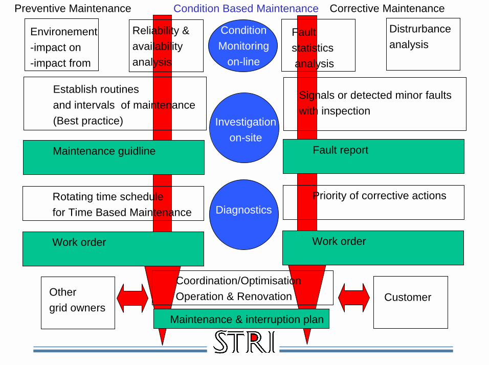
Establish routinesand intervals of maintenance (Best practice)
Maintenance guidline
Rotating time schedulefor Time Based Maintenance
Work order
Environement-impact on-impact from
Reliability &availabilityanalysis
Signals or detected minor faultswith inspection
Fault report
Priority of corrective actions
Work order
Fault statisticsanalysis
Distrurbanceanalysis
Preventive Maintenance Corrective Maintenance
ConditionMonitoring
on-line
Investigationon-site
Diagnostics
Condition Based Maintenance
Othergrid owners
Coordination/OptimisationOperation & Renovation
Maintenance & interruption plan
Customer

200 - 800 kV
Industry
Generation
Transmission
Distribution
6 - 200 kV
Your SOLA Line diagnostics site
! Insulators! Line joints! Towers! ????
! Data base with flexible browser for statistics, trends, mutual dependance per type, age, climate, location manufacturer etc.

200 - 800 kV
Industry
Generation
Transmission
Distribution
6 - 200 kV
Your SOLA system monitoring site
= In critical locations
! Temperature! Leakage current! Ice loading + frost
! On-line monitoring for evaluation of different design and/or early warning to operation

200 - 800 kV
Industry
Generation
Transmission
Distribution
6 - 200 kV
Your SOLA Substation diagnostics site
= In critical substations
! Breakers! Disconnectors! Transformers
! On-line diagnostics for evaluation of trends & fingerprints for early warning to maintenance

Content – State-of-the-art technology! Introduction to STRI! What is reliability centered design ?! New substation design with composite insulation! Software to optimize & compare availability for
substations! New transmission line design with composite insulation! Software to optimize & compare availability for
transmission line! What is reliability centered maintenance? ! New possibilities with SOLA on line diagnostics! New possibilities with IEC 61850 on line

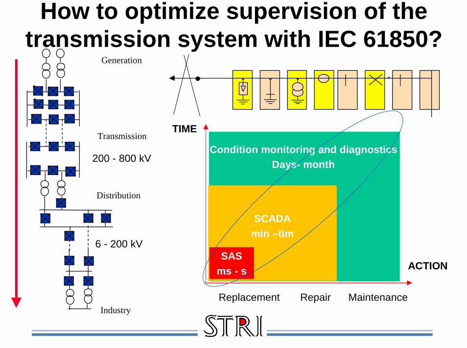
! Substation Automation, Control & Protection (ms -s)! An electrical failure should be detected and cleared with
selectivity with milliseconds form the protection! Additional time delayed protection is available for abnormal
conditions and breaker failure! SCADA/EMS (min-hour)
! The SCADA system provides information to the control centre to supervise the operation and to preventdangerous operation. These actions is normally in the range minutes to hours
! Condition Monitoring and Diagnostics (day –months)! Condition monitoring (on-line or on-site) evaluates the
condition and analyses trends of the equipment in order to determine necessary maintenance, renovation or replacement
Supervising the power system

What, Where, When, Who and then How
IED HMI
Station HSI
Control Centrel Office Home Station Anywhere(On line) (On request)

StationAutomation
StationAutomation
Driftcentral Driftcentral
SPA, LON, DNP 3.0, MODBUS, UCA 2, Profibus, IEC60 870-5-103, K-Bus, ZZZ
IEC60870-6 (TASE2)
SCADAIEC60870-5-101IEC60870-5-104DNP 3.0ELCOM 90RP570/571XXX
EnergimätningIEC61107IEC62056IEC60870-5-102YYY
VindkraftIEC51400-25
IEC G703IEEE C37.94WWW
IEC 61850
= IEC 61850
IEC61970 (CIM)
But why do we need so manyprotocols (and protocol converters)?

200 - 800 kV
Industry
Generation
Transmission
Distribution
6 - 200 kV
Your integrated supervision with IEC 61850
SCADAmin. –hours
SASms - s
Time
CM & Diagnosticsdays to months
Replacement Renovation Maintenance
Action

The ability for IED’s from one or severalmanufacturers to exchange information and use
the information for their own functions
The standard shall support different architecture and allow a free allocation of
functions. E.g. it must work equally well for centralized or decentralized systems.
The standard shall be future proof, i.e. it must be able to follow the progress in
communication technology as well as evolving system requirements
Trend: IEC 61850 for protection and control
IED = Intelligent Electronic Device

Vhat is the new IEC 61850 standard?

A global standard for datamodelling and information exchange...
...in Network Automation

Separation allows technical evolution
Aplication:- E.g. protection
Service:- E.g. report
Communication:- E.g TCP/IP Ethernet
Data model
Service model
Mapping

Vhat is 61850 open communication?Base:! ISO/OSI TCP/IP 7 level standard! Ethernet 100 MBps + GOOSE! Common model and language! Common IEC & ANSI standard
More than a protocol:! Structured data model! Meaningful text instaead of code! Flexible architecture with free allocation! Structured configuration of services
New possibilities:! High speed horisontal & vertical integration! Flexible integration & automation! Interoperability between vendors! Optimized & Future proof solutions
Omicron
Areva
Siemens
ABB

IEC 68150 open communication
MMS = Manufacturing Message Specification ISO 9506

GOOSE
! Peer to peer prioriterad kommunikation max 4 ms! En IED skickar infromation med multicasting! Bara en IED som är definierad att lyssna
(prenumerant) får meddelandet
GOOSE = Generic Object Oriented System-wide Events
Vhat is GOOSE?

Vhat is interoperabilty
!Common standrad for!language (Data modell) ! Services (Service modell)!Communication protocol!Communication media!Dataexchange (For engineering and operation)!Conformity test

Comparison with other protocols

Example of data model
IED1/C3CSWI3.Pos.ctIVal
!E.g. Control of breakersLogisk Device namn (Fri)
Logisk Nod prefix (Fri)Logisk Nod klass (Fast)
Logisk node suffix (Fri)Data objekt (Fast)
Attribut (Fast)

FunctionE.g. Distance protection
Config.data
In data Out data
Standardized data exchange

XCBR Breaker
PDIS Distance prot.PIOC Inst. O/C
CSWI Switch control
MMXU Measurement
Examples of locical nodes (~100)

! ACSI = Abstract Communications Service Interface
! ACSI define how data is collected but not where it is located
! En multifunctional IED can be Locical Nodefor several applications
! This alows free allocation of functions to any IED, I.e. centralized or distributed (If the vendor has fully implemnted the ”soft library”)
Vhat is ACSI?

Service for data access och transfer

IEC 61850 configuration! Common language = Substation Configuration
descriptive Language = SCL i XML format! IEC 61850 define four different files
! ICD = IED Capability Description which describes each IED with LN and data
! SSD = System Specification Description with single linediagram and function allocation
! SCD = Station Configuration Description is the completeconfiguration of all IEDs in a substation with process signals and communication structure
! CID = Configured IED Description include complete IED with vendor specific configuration

IEC 61850 configuration

IEC 61850 configuration tool is necessary !
(ABB PCM 600 example)

(Siemens DIGSI4 example)
IEC 61850 configuration tool is necessary !

(Areva MICOM S1 example)
IEC 61850 configuration tool is necessary !

IEC 61850 independent tools
(SCL validator example)

IEC 61850 independent tools
(Ase-systems Visual SCL example)

IEC 61850 independent tools
(Kalki protocol converter example)

IEC 61850 independent tools
(Omicron IEDScout example)

Example Areva! Areva introduced C264
RTU designed for IEC 61850
! Areva has now designedinterfaces for a number of existing IEDs

Example Areva

Example Siemens! Siemens give firmware
upgrade for SIPROTEC4Vhich version is listed inwww.siprotec.com
! EN100 Ethernet interface modul needed
! Optical or electricalEthernet
! IED ring possible with optical

Example ABB! ABB has developed a
complete new productgeneration based on 61850 in the 600 series E.g. REL 670 with a common Application Function Library
! Some existing productscan be connected via modem, e.g. REF 541

Example ABB
!SAS610 Centralized ring
!SAS670 Decentralized ring

Exampel RUGGEDCOM
! RUGGEDCOM has Ethernet switches designed for IEC 61850 which can handle priority tagging and avoid collisions

IEC 61850 conformity by KEMA/UCA

IEC 61850 GOOSE verification

IEC 61850 interoperability
ABB System verification center Several multi vendor applications are now in service

Station Bus IEC 61850-8-1
TCP/IP Monitoring Bus
IEC 870-5-101/104
Remote workplace in the office or in the field
Utility office LAN Utility
WAN/Internet
Utility substation
LAN
Process Bus IEC 61850-9-2
Internet & 61850 in the station
ON-LINE Monitoring Device

Example for control
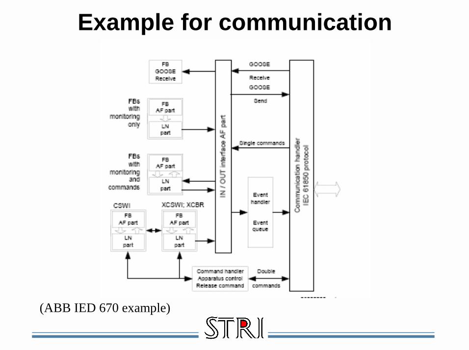
Example for communication
(ABB IED 670 example)

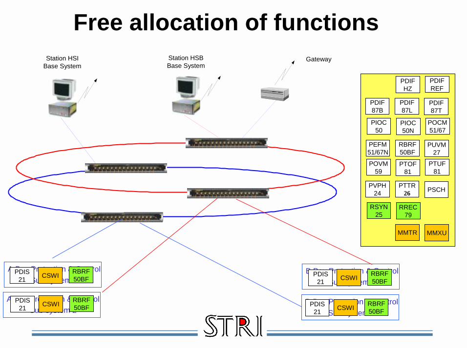
Free allocation of functions
RBRF50BF
RREC79
MMXUMMTR
RSYN25
CSWI
PTUF81
PTOF81
PSCHPTTR49
POVM59
PVPH24
POCM51/67
PIOC50N
PUVM27PGPF
PIOC50
PEFM51/67N
PDIFREF
PDIFHZ
PDIF87T
PDIF87L
PDIS21
PDIF87B
PDIS21
RREC79
MMTR
PDIS21
POCM51/67
RBRF50BF
RREC79
RSYN25
MMXUMMTRCSWI
PDIF87L
PDIS21
PDIFHZ
POCM51/67
RBRF50BF
RREC79
RSYN25
MMXUMMTRCSWI
PDIF87T
PGPF
PVPH24
B24PDIF 87B Bus differential protectionL6CPDIF 87L Line differential protectionT3WPDIF 87T Transformer differential protectionREFPDIF 87N Low impedance differential protectionHZ PDIF 87 High impedance differential protection
ZMQPDIS 21 Distance protectionPH4POCM 51/67 Overcurrent protectionEF4PEFM 51N/67N Overcurrent protectionPOVM 27/59 Overcvoltage protectionPTUF 81 Under frequency protectionPTOF 81 Over frequency protectionPVPH 24 Over excitation protectionLPTTR 26 Overload protectionPGPF XXX Programmable general current/voltage functionCRBRF 50BF Breaker failure protectionRSYN 25 Synchro checkRREC 79 Auto reclosingCSWI ControlRFLO Fault locatorRADR Disturbance reportingMMXU MeasurementMMTR Pulse counter

Station HSIBase System Gateway
A Bay Protection & ControlSub system 1
B Bay Protection & ControlSub system 1
B Bay Protection & ControlSub system 2
A Bay Protection & ControlSub system 2
RBRF50BF
RREC79
MMXUMMTR
RSYN25
CSWI
PTUF81
PTOF81
PSCHPTTR26
POVM59
PVPH24
POCM51/67
PIOC50N
PUVM27
RBRF50BF
PIOC50
PEFM51/67N
PDIFREF
PDIFHZ
PDIF87T
PDIF87L
PDIS21
PDIF87B
Free allocation of functions

Station HSIBase System Gateway
A Bay Protection & ControlSub system 1
B Bay Protection & ControlSub system 1
B Bay Protection & ControlSub system 2
A Bay Protection & ControlSub system 2
RREC79
MMXUMMTR
RSYN25
PTUF81
PTOF81
PSCHPTTR26
POVM59
PVPH24
RBRF50BFCSWI POCM
51/67
PUVM27
PTTR26
PEFM51/67N
PDIFREF
PDIFHZ
PDIF87T
PDIF87L
PIOC50N
PIOC50
PDIS21
PDIF87B
PIOC50N
PIOC50
PDIS21
RBRF50BFCSWI POCM
51/67
Free allocation of functions

Station HSIBase System Gateway
A Bay Protection & ControlSub system 1
B Bay Protection & ControlSub system 1
B Bay Protection & ControlSub system 2
A Bay Protection & ControlSub system 2
RREC79
MMXUMMTR
RSYN25
PTUF81
PTOF81
PSCHPTTR26
POVM59
PVPH24
POCM51/67
PIOC50N
PUVM27
RBRF50BF
PIOC50
PEFM51/67N
PDIFREF
PDIFHZ
PDIF87T
PDIF87L
RBRF50BFCSWIPDIS
21
PDIF87B
RBRF50BFCSWIPDIS
21
RBRF50BFCSWIPDIS
21
RBRF50BFCSWIPDIS
21
Free allocation of functions
Station HSIBase System
Gateway
A Bay Protection & ControlSub system 1
B Bay Protection & ControlSub system 1
B Bay Protection & ControlSub system 2
A Bay Protection & ControlSub system 2
RREC79
MMXUMMTR
RSYN25
PTUF81
PTOF81
PSCHPTTR26
POVM59
PVPH24
POCM51/67
PIOC50N
PUVM27
RBRF50BF
PIOC50
PEFM51/67N
PDIFREF
PDIFHZ
PDIF87T
PDIF87L
RBRF50BFCSWIPDIS
21
PDIF87B
RBRF50BFCSWIPDIS
21
RBRF50BFCSWIPDIS
21
RBRF50BFCSWIPDIS
21
Station HSBBase System
Free allocation of functions

Station HSIBase System Gateway
4 Bay Protection & ControlSub system 1
4 Bay Protection & ControlSub system 2
RBRF50BF
RREC79
MMXUMMTR
RSYN25
CSWI
PTUF81
PTOF81
PSCHPTTR26
POVM59
PVPH24
POCM51/67
PIOC50N
PUVM27
RBRF50BF
PIOC50
PEFM51/67N
PDIFREF
PDIFHZ
PDIF87T
PDIF87L
PDIS21
PDIF87B
Free allocation of functionsIntegrated

Station HSIBase System Gateway
Station Protection & ControlSub system 1
RREC79
MMXUMMTR
RSYN25
PTUF81
PTOF81
PSCHPTTR26
POVM59
PVPH24
PIOC50N
PUVM27
RBRF50BF
PIOC50
PEFM51/67N
PDIFREF
PDIFHZ
PDIF87T
PDIF87L
PDIF87B
Station Protection & ControlSub system 2
I/O I/OI/OI/O I/O I/O
RBRF50BF CSWI
POCM51/67
PDIS21PDIS
21POCM51/67
RBRF50BF CSWI
RBRF50BF CSWI
POCM51/67
PDIS21PDIS
21POCM51/67
RBRF50BF CSWI
Free allocation of functionsDistributed

IEC 61850 continues

New energy
Vidkraft:WROT VindturbinrotorWAPC Vindkraft aktiv effektregulator
Vattenkraft:ASPC varvtalsregulatorAMWR aktiv effektregulator
DER – Distribuerad Energi:DFCL BränslecellDRAT DER generatordata

HVAC Transmission
HVDC Transmission
Distribution S/S
Industrial S/S
Electrification
Transmission S/SGeneration
Continuous supply of electrical energy
Sub transmission S/S
Internet & 61850 everywhere
IEC 62271-3 based on IEC 61850for HV Switchgear
IEC 61850 –7-3 and 7.4extension for PQ
IEC 61850 –7-420Extension for DER
IEC 61850 for substations
IEC 61400-25 based on IEC 61850for Wind Power
IEC 62344 based on IEC 61850for Hydro Power Plants
200 - 800 kV
Industry
Generation
Transmission
Distribution
6 - 200 kV
How to optimize supervision of the transmission system with IEC 61850?
SCADAmin –tim
SASms - s
TIME
Condition monitoring and diagnosticsDays- month
Replacement Repair Maintenance
ACTION

So what can STRI do for you?! STRI has a unique competence within the
High Voltage area for both HVAC and HVDC applications with design, application & diagnostics
! In our international projects we are following, testing and verifying state-of-the-art solutions
! Our combination of STRI Testing, STRI Software and STRI Consulting resources makes it possible to assist you in finding an optimum solution to your application – and to verify it
! We are independent and accredited so we can work with you for the best solution available by integrating different manufacturers & technology

What can STRI do to assist you in your implemenation of new technology?
! Independent evaluation and accredited testing of equipment & insulation! System studies to review the effect and feasibility of different alternatives
(HVAC or HVDC, Upgrading HVAC or conversion to HVDC, Wind Power etc.)! Selection of optimum insulation and towers for HVAC and HVDC depending on
electrical and environmental parameters and required availability! Calculation of temporary dynamic load depending on application & weather! Calculation (and measurement) of EM field for different solutions! Implementation of new technology for compact substations & transmission lines! Implementation of high voltage cables including quality assurance & diagnostics! Comparing reliability and availability of different solutions! Evaluating and implementing on-line diagnostics including pollution & weather
monitoring on critical components for Condition Based Maintenance! Evaluate and implement state-of-the-art solution for fault detection & location! Optimized implementation of IEC 61850 for integration of control, protection &
monitoring and to convert data to useful information ! Implement a structured Asset Management process based on Reliability
Centered Maintenance

Accredited for testing and calibrationISO9001 certified for quality system
Learn more on www.stri.se

Learn more on www.stri.se

How do we work ?
Idea!, problem ? or requirement = ! Identification
! Specification
! Calculation
! Allocation
! Implementation
Specification of goal & method
Work package and cost
Time and resource allocation
Presentation and implementation

Your independent partner for high voltage technology
and applications
Thank you for your attention!