Embed Size (px)
Citation preview

1 1 1
Heat flow in welds
Welding Lecture - 12 27 September, 2016, Tuesday 11.00 -11.50 am
2
Solidification rate • The rate at which weld metal solidifies can
have a profound effect on its microstructure, properties, and response to post weld heat treatment.
• The solidification time, St, in seconds, is given by
3
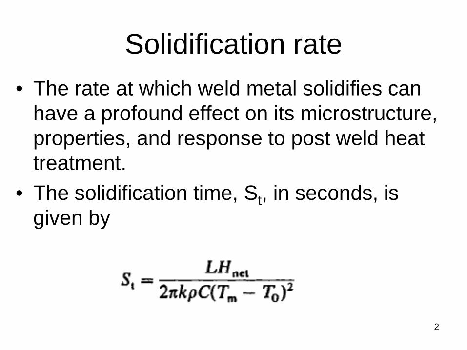
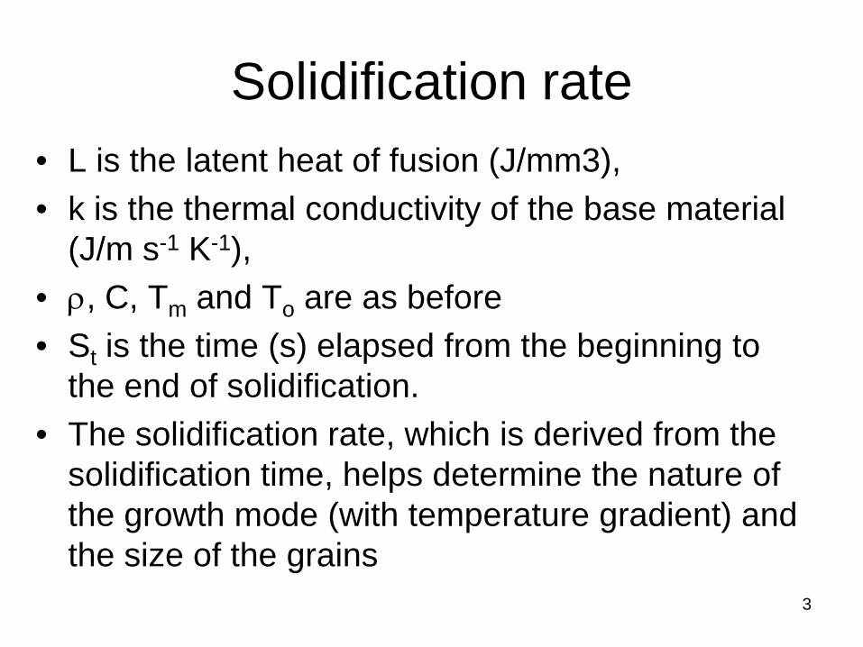
Solidification rate • L is the latent heat of fusion (J/mm3), • k is the thermal conductivity of the base material
(J/m s-1 K-1), • ρ, C, Tm and To are as before • St is the time (s) elapsed from the beginning to
the end of solidification. • The solidification rate, which is derived from the
solidification time, helps determine the nature of the growth mode (with temperature gradient) and the size of the grains
4
Cooling Rates
• The rate of cooling influences – the coarseness or fineness of the resulting structure – the homogeneity, the distribution and form of the phases and
constituents in the microstructure, of both the FZ and the HAZ for diffusion controlled transformations
• Cooling rate determines which transformation (phase) will occur and, thus, which phases or constituents will result.
• If cooling rates are too high in certain steels → hard, untempered martensite → embrittling the weld → adds susceptibility to embrittlement by hydrogen.
• By calculating the cooling rate, it is possible to decide whether undesirable microstructures are likely to result.
• Preheat → To reduce the cooling rate. Cooling rate is primarily calculated to determine the need for preheat.
5
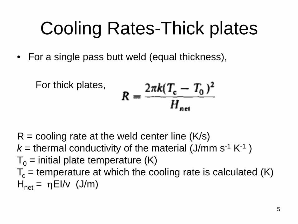
Cooling Rates-Thick plates • For a single pass butt weld (equal thickness),
R = cooling rate at the weld center line (K/s) k = thermal conductivity of the material (J/mm s-1 K-1 ) T0 = initial plate temperature (K) Tc = temperature at which the cooling rate is calculated (K) Hnet = ηEI/v (J/m)
For thick plates,
6
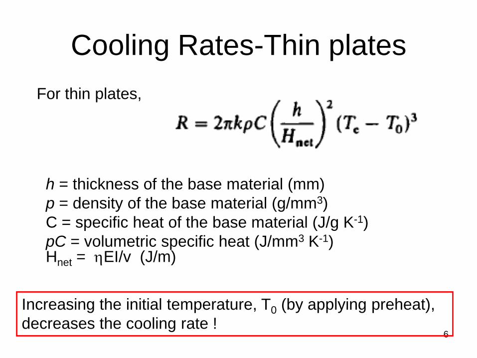
Cooling Rates-Thin plates For thin plates,
h = thickness of the base material (mm) p = density of the base material (g/mm3) C = specific heat of the base material (J/g K-1) pC = volumetric specific heat (J/mm3 K-1) Hnet = ηEI/v (J/m)
Increasing the initial temperature, T0 (by applying preheat), decreases the cooling rate !
7
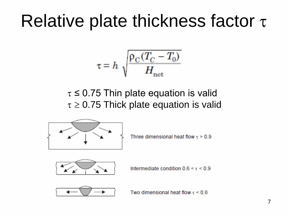
Relative plate thickness factor τ
τ ≤ 0.75 Thin plate equation is valid τ ≥ 0.75 Thick plate equation is valid

8
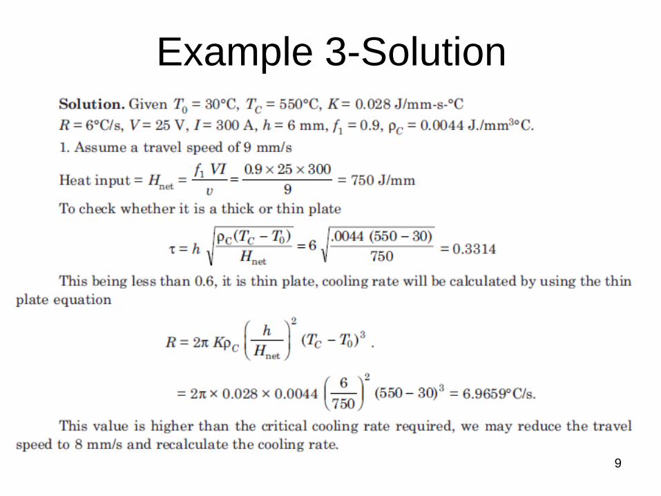
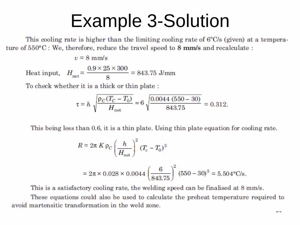
Example 3
Find the best welding speed to be used for welding 6 mm steel plates with an ambient temperature of 30 °C with the welding transformer set at 25 V and current passing is 300 A. The arc efficiency is 0.9 and possible travel speeds ranges from 5-10 mm/s. The limiting cooling rate for satisfactory performance is 6 °C/s at a temperature of 550 °C.
k=0.028 J/mm.s.K pC= 0.0044 J/mm3K
9
Example 3-Solution
10
Example 3-Solution
11 11
Solid state welding processes
Welding Lecture - 13 04 October, 2016 Tuesday 10.00 -11.00 am
12
Solid state/Nonfusion welding • Accomplish welding by bringing the atoms (or
ions or molecules) to equilibrium spacing → through plastic deformation → application of pressure at temperatures below the melting point of the base material
• Without the addition of any filler • Chemical bonds are formed and a weld is
produced as a direct result of the continuity obtained, → always with the added assistance of solid-state diffusion
13
Solid state/Nonfusion welding 1. Pressure Welding → By pressure and
gross deformation 2. Friction welding → By friction and
microscopic deformation 3. Diffusion welding → By diffusion,
without or with some deformation 4. Deposition welding → Solid-state
deposition welding
14
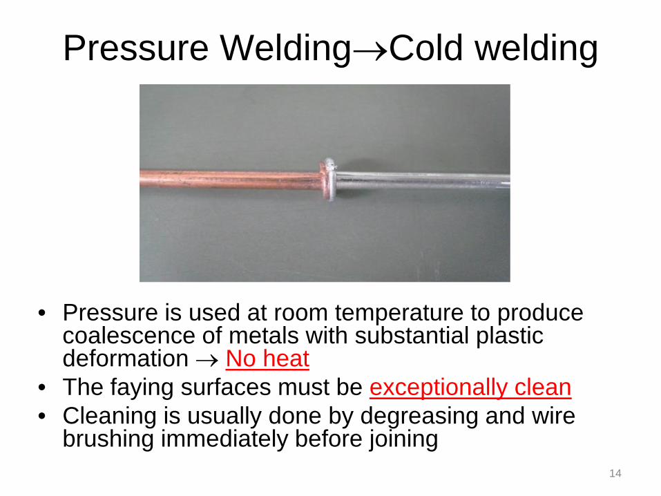
Pressure Welding→Cold welding
• Pressure is used at room temperature to produce coalescence of metals with substantial plastic deformation → No heat
• The faying surfaces must be exceptionally clean • Cleaning is usually done by degreasing and wire
brushing immediately before joining
Pressure Welding →Cold welding
• At least one of the metals to be joined must be highly ductile and not exhibit extreme work hardening
• FCC metals and alloys are best suited for CW. Example- Al, Cu, and Pb
• To a lesser degree, Ni and soft alloys of these metals such as brasses, bronzes, babbitt metals (Sn, Cu, Sb, Pb), and pewter (Sn, Cu, Sb, Bi)
• Precious metals, Au, Ag, Pd, and Pt, are also ideally suited to cold welding, as they are face-centered cubic (soft) and are almost free of oxides
15
16
Pressure Welding → Cold welding • Ideal for joining of dissimilar metals → no
intermixing of the base metals is required • Allows inherent chemical incompatibilities that
make fusion welding difficult to be overcome • E.g. → Cold welding of relatively pure Al to
relatively pure Cu → Electrical connections • Formation of brittle intermetallics (e.g., AI,Cu)
→ either during postweld heat treatment or in service, (resistance heating in the electrical connector)
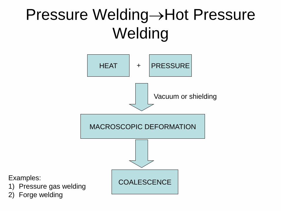
Pressure Welding→Hot Pressure Welding
HEAT PRESSURE
COALESCENCE
Vacuum or shielding
+
Examples: 1) Pressure gas welding 2) Forge welding
MACROSCOPIC DEFORMATION

18
Pressure Welding→ Forge welding (FOW)
• Earliest form of welding → still used today by blacksmiths
• Produces the weld by heating work pieces to hot working temperatures and applying blows sufficient to cause deformation at the faying surfaces
• Low-carbon steels (most commonly forge-welded metal), high-carbon steel
19
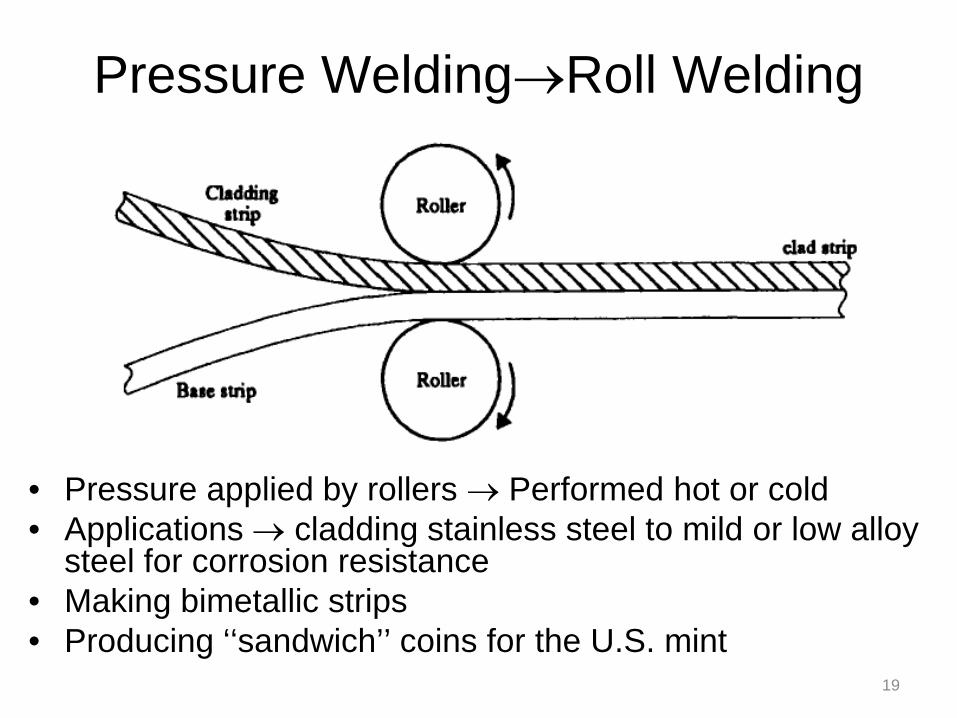
Pressure Welding→Roll Welding
• Pressure applied by rollers → Performed hot or cold • Applications → cladding stainless steel to mild or low alloy
steel for corrosion resistance • Making bimetallic strips • Producing ‘‘sandwich’’ coins for the U.S. mint
20
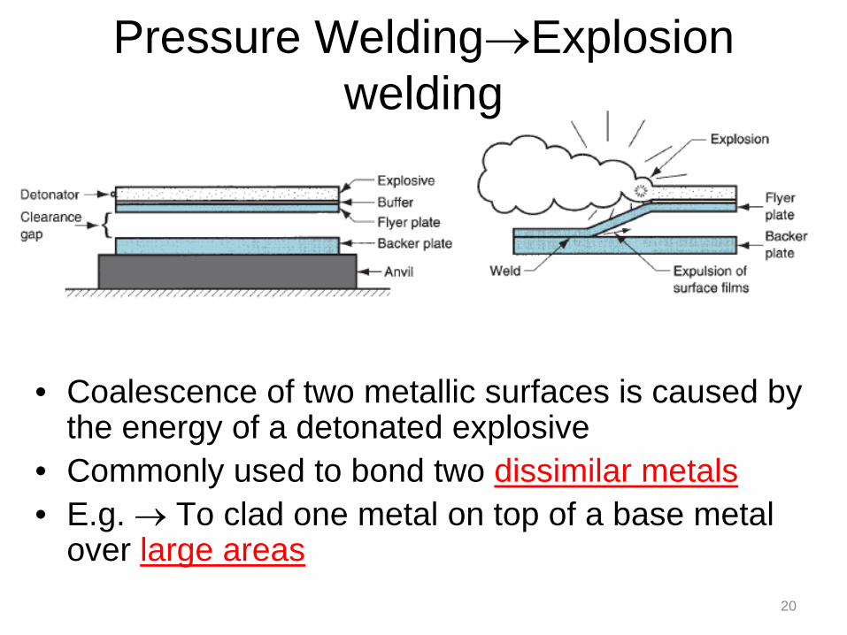
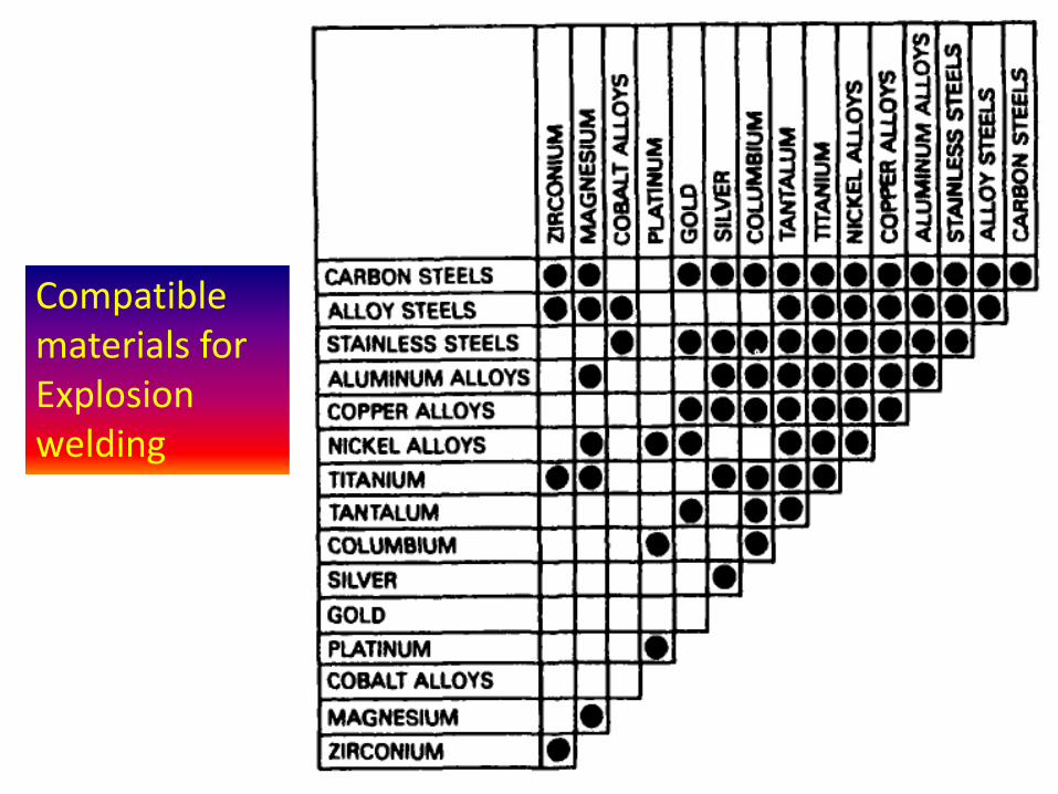
Pressure Welding→Explosion welding
• Coalescence of two metallic surfaces is caused by the energy of a detonated explosive
• Commonly used to bond two dissimilar metals • E.g. → To clad one metal on top of a base metal
over large areas
21
Pressure Welding→Explosion welding: Applications
• Applications include production of corrosion-resistant sheet and making processing equipment in the chemical and petroleum industries
• E.g. Commercially pure titanium clad to mild steel
• Often performed under water to enhance the shock wave to move and deform material
22
Compatible materials for Explosion welding

23
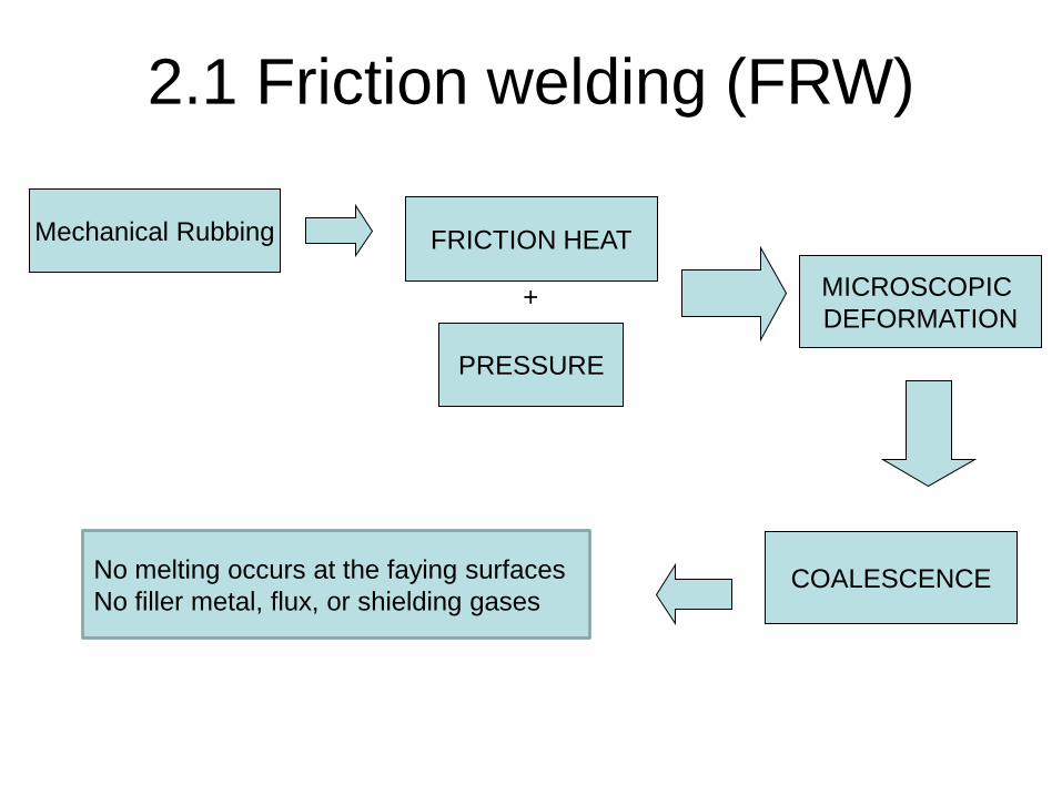
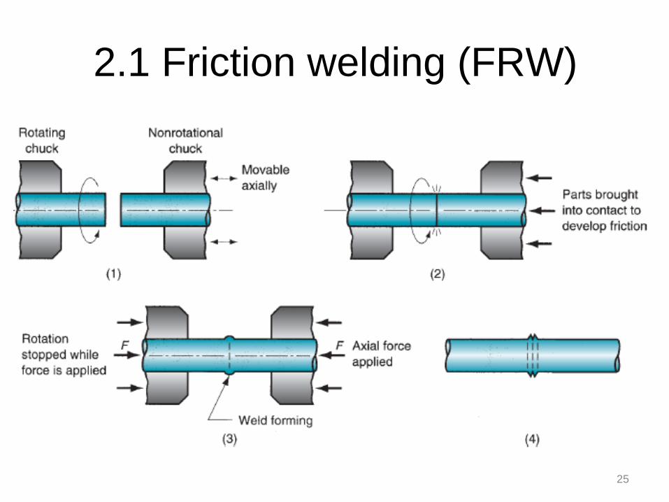
2.1 Friction welding (FRW)
• Solid state welding → Coalescence is achieved by frictional heat combined with pressure
• Friction is induced by mechanical rubbing between two surfaces → usually by rotation of one part relative to the other → raises the temperature at the joint interface to the hot working range → Parts are driven toward each other with sufficient force to form a metallurgical bond
COALESCENCE
MICROSCOPIC DEFORMATION
2.1 Friction welding (FRW)
Mechanical Rubbing FRICTION HEAT
PRESSURE
+
No melting occurs at the faying surfaces No filler metal, flux, or shielding gases
25
2.1 Friction welding (FRW)
26
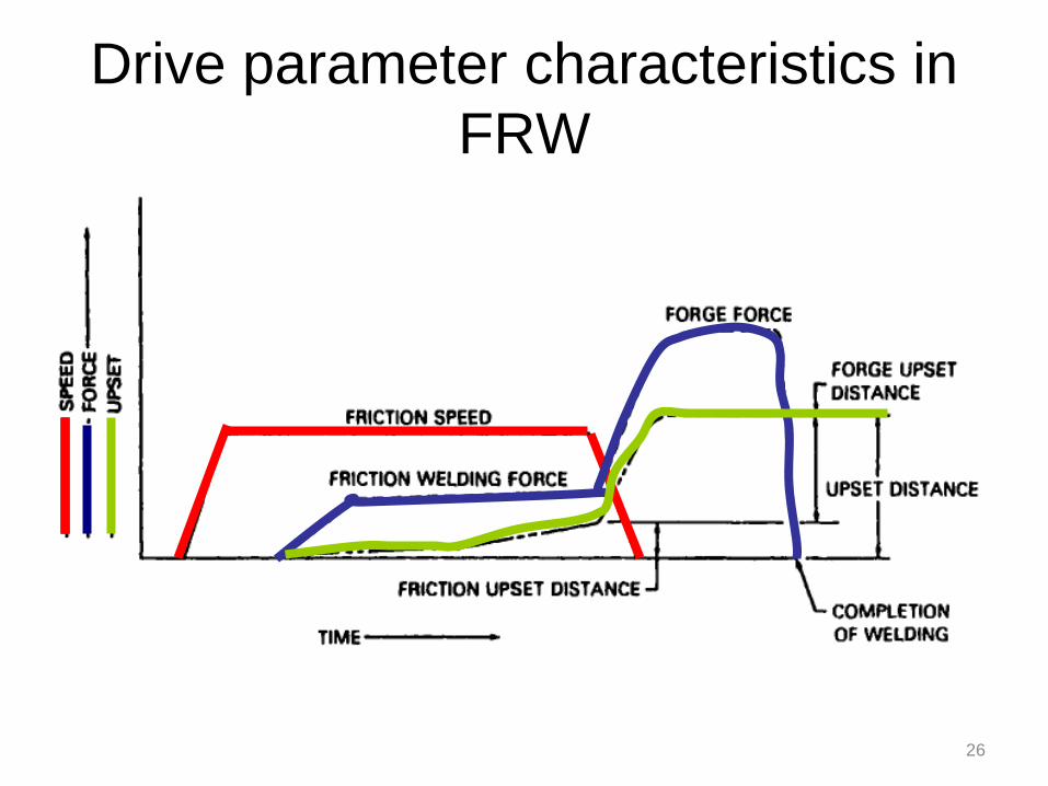
Drive parameter characteristics in FRW
27
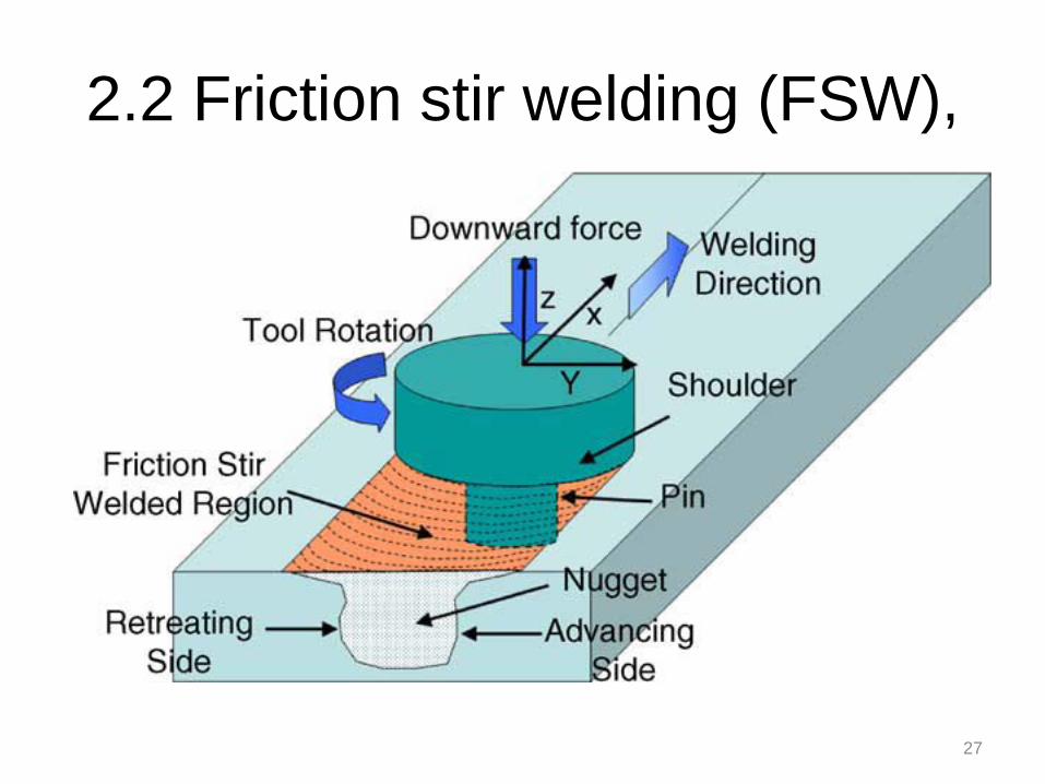
2.2 Friction stir welding (FSW),
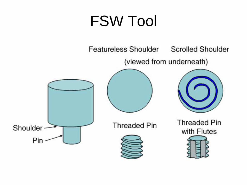
FSW Tool
29
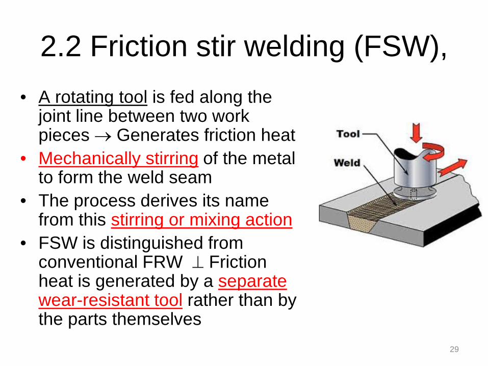
2.2 Friction stir welding (FSW), • A rotating tool is fed along the
joint line between two work pieces → Generates friction heat
• Mechanically stirring of the metal to form the weld seam
• The process derives its name from this stirring or mixing action
• FSW is distinguished from conventional FRW ⊥ Friction heat is generated by a separate wear-resistant tool rather than by the parts themselves
30
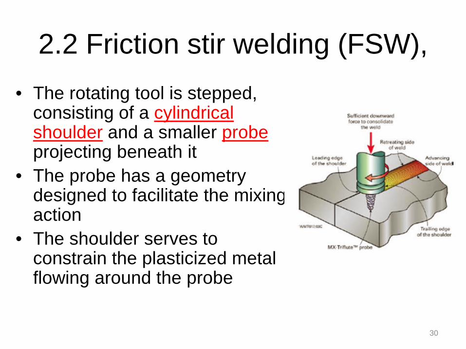
2.2 Friction stir welding (FSW), • The rotating tool is stepped,
consisting of a cylindrical shoulder and a smaller probe projecting beneath it
• The probe has a geometry designed to facilitate the mixing action
• The shoulder serves to constrain the plasticized metal flowing around the probe

2.2 Friction stir welding (FSW), • During welding, the shoulder rubs
against the top surfaces of the two parts, developing much of the friction heat
• While the probe generates additional heat by mechanically mixing the metal along the butt surfaces
• The heat produced by the combination of friction and mixing does not melt the metal but softens it to a highly plastic condition 31
32
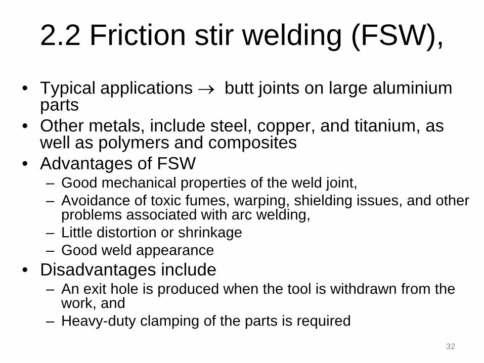
2.2 Friction stir welding (FSW), • Typical applications → butt joints on large aluminium
parts • Other metals, include steel, copper, and titanium, as
well as polymers and composites • Advantages of FSW
– Good mechanical properties of the weld joint, – Avoidance of toxic fumes, warping, shielding issues, and other
problems associated with arc welding, – Little distortion or shrinkage – Good weld appearance
• Disadvantages include – An exit hole is produced when the tool is withdrawn from the
work, and – Heavy-duty clamping of the parts is required
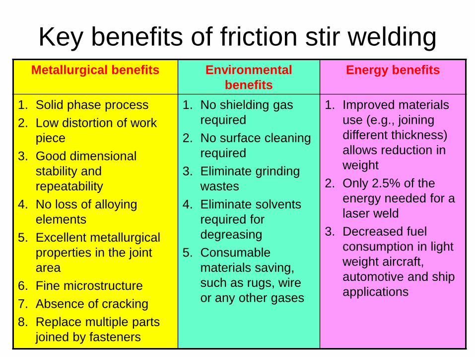
Key benefits of friction stir welding Metallurgical benefits Environmental
benefits Energy benefits
1. Solid phase process 2. Low distortion of work
piece 3. Good dimensional
stability and repeatability
4. No loss of alloying elements
5. Excellent metallurgical properties in the joint area
6. Fine microstructure 7. Absence of cracking 8. Replace multiple parts
joined by fasteners
1. No shielding gas required
2. No surface cleaning required
3. Eliminate grinding wastes
4. Eliminate solvents required for degreasing
5. Consumable materials saving, such as rugs, wire or any other gases
1. Improved materials use (e.g., joining different thickness) allows reduction in weight
2. Only 2.5% of the energy needed for a laser weld
3. Decreased fuel consumption in light weight aircraft, automotive and ship applications
2.3 Ultrasonic welding (USW)
34
2.3 Ultrasonic welding (USW)
• Two components are held together under modest clamping force
• Oscillatory shear stresses of ultrasonic frequency are applied to the interface to cause coalescence
• Oscillatory motion between the two parts breaks down any surface films → allows intimate contact and strong metallurgical bonding between the surfaces
35
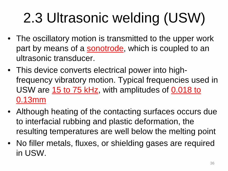
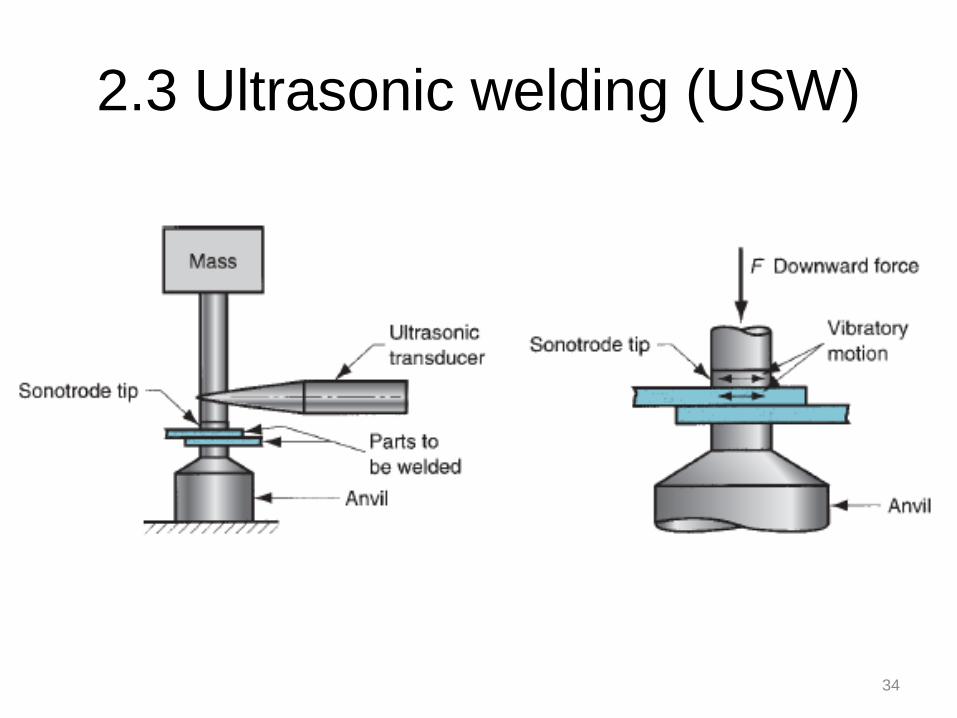
2.3 Ultrasonic welding (USW) • The oscillatory motion is transmitted to the upper work
part by means of a sonotrode, which is coupled to an ultrasonic transducer.
• This device converts electrical power into high-frequency vibratory motion. Typical frequencies used in USW are 15 to 75 kHz, with amplitudes of 0.018 to 0.13mm
• Although heating of the contacting surfaces occurs due to interfacial rubbing and plastic deformation, the resulting temperatures are well below the melting point
• No filler metals, fluxes, or shielding gases are required in USW.
36
2.3 Ultrasonic welding (USW)
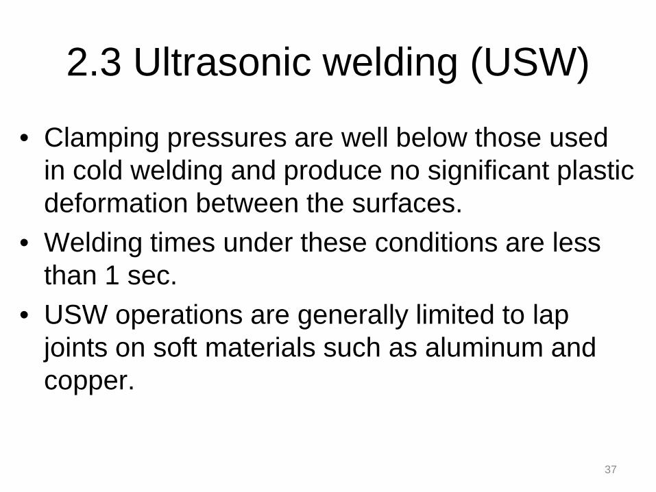
• Clamping pressures are well below those used in cold welding and produce no significant plastic deformation between the surfaces.
• Welding times under these conditions are less than 1 sec.
• USW operations are generally limited to lap joints on soft materials such as aluminum and copper.
37
38 38
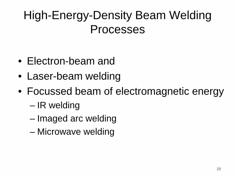
High-Energy-Density Beam Welding Processes
• Electron-beam and • Laser-beam welding • Focussed beam of electromagnetic energy
– IR welding – Imaged arc welding – Microwave welding
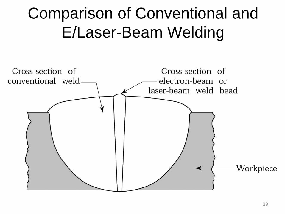
Comparison of Conventional and E/Laser-Beam Welding
39

40 40
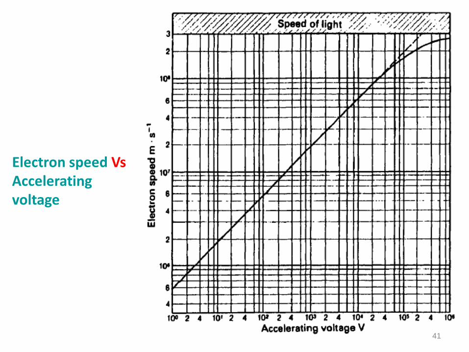
Electron-beam welding (EBW) • Uses kinetic energy of
dense focused electrons • Electrons emitted by
cathode, accelerated by ring shaped anode, focused by electromagnetic field
• High energy density 10 MW/mm2
• Heat focus on few micrometers
• Vacuum chamber
41
Electron speed Vs Accelerating voltage

42
E-Beam interaction with work piece
43
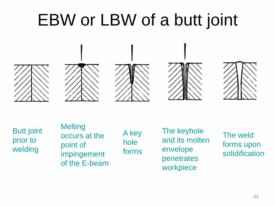
EBW or LBW of a butt joint
Butt joint prior to welding
Melting occurs at the point of impingement of the E-beam
A key hole forms
The keyhole and its molten envelope penetrates workpiece
The weld forms upon solidification
44 44
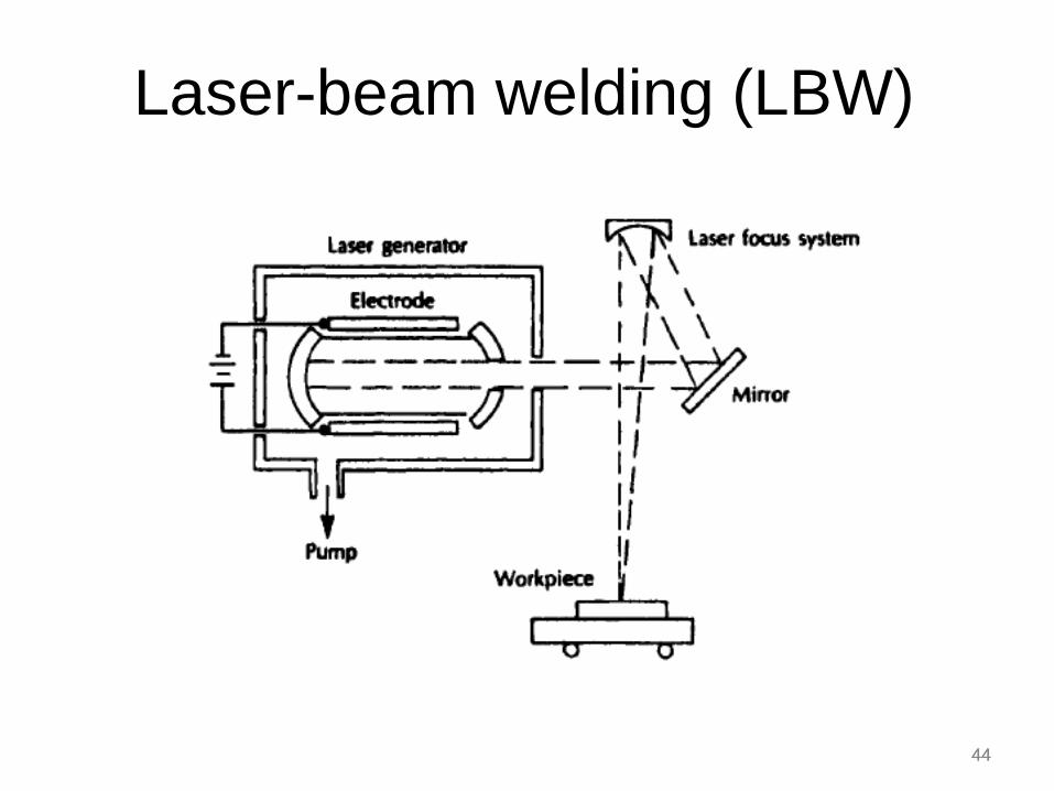
Laser-beam welding (LBW)

45
Laser-beam welding • Coalescence is achieved by the energy of a highly
concentrated, coherent light beam focused on the joint to be welded
• LBW is normally performed with shielding gases (e.g., helium, argon, nitrogen, and carbon dioxide) to prevent oxidation
• No vacuum chamber is required, no X-rays are emitted
• Laser beams can be focused and directed by optical lenses and mirrors.
• LBW does not possess the capability for the deep welds and high depth-to-width ratios of EBW
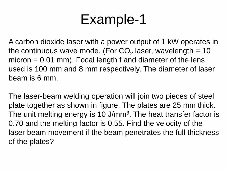
Example-1 A carbon dioxide laser with a power output of 1 kW operates in the continuous wave mode. (For CO2 laser, wavelength = 10 micron = 0.01 mm). Focal length f and diameter of the lens used is 100 mm and 8 mm respectively. The diameter of laser beam is 6 mm. The laser-beam welding operation will join two pieces of steel plate together as shown in figure. The plates are 25 mm thick. The unit melting energy is 10 J/mm3. The heat transfer factor is 0.70 and the melting factor is 0.55. Find the velocity of the laser beam movement if the beam penetrates the full thickness of the plates?
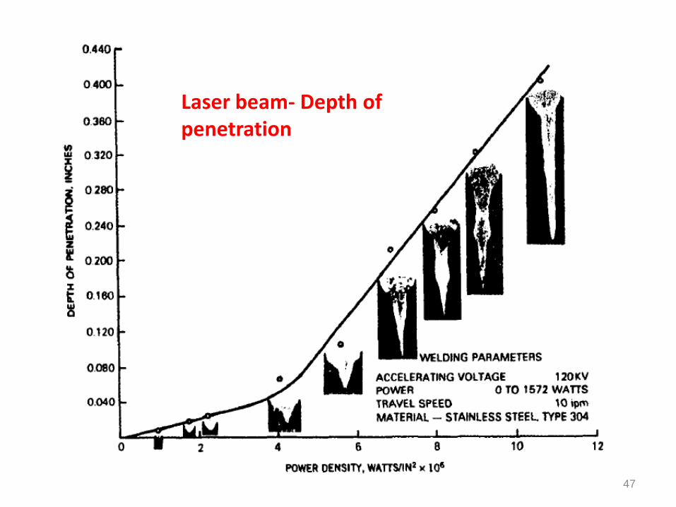
47
Laser beam- Depth of penetration
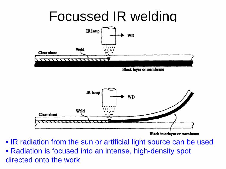
Focussed IR welding
• IR radiation from the sun or artificial light source can be used • Radiation is focused into an intense, high-density spot directed onto the work
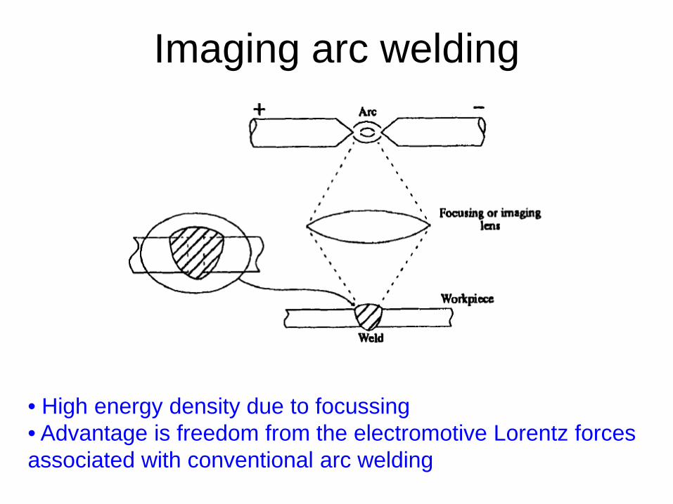
Imaging arc welding
• High energy density due to focussing • Advantage is freedom from the electromotive Lorentz forces associated with conventional arc welding
50 50
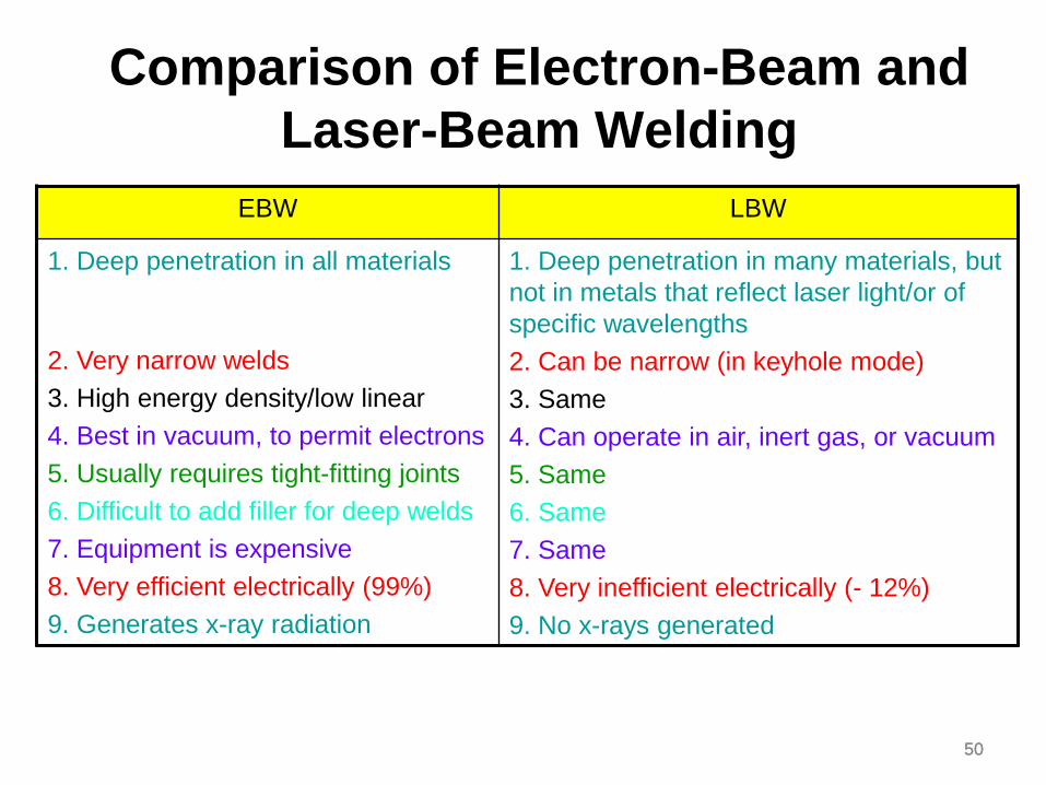
Comparison of Electron-Beam and Laser-Beam Welding
EBW LBW
1. Deep penetration in all materials
2. Very narrow welds 3. High energy density/low linear 4. Best in vacuum, to permit electrons 5. Usually requires tight-fitting joints 6. Difficult to add filler for deep welds 7. Equipment is expensive 8. Very efficient electrically (99%) 9. Generates x-ray radiation
1. Deep penetration in many materials, but not in metals that reflect laser light/or of specific wavelengths 2. Can be narrow (in keyhole mode) 3. Same 4. Can operate in air, inert gas, or vacuum 5. Same 6. Same 7. Same 8. Very inefficient electrically (- 12%) 9. No x-rays generated
51 51 51
Design of Weld joints
Welding Lecture - 14 18 October, 2016 Tuesday 10.00 -11.00 am
(Refer class notes)
52
Design of Weld joints
53
54
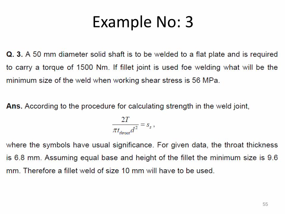
55
Example No: 3
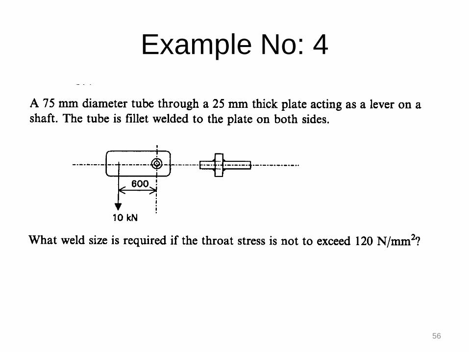
56
Example No: 4
57 57 57
Welding Lecture - 15 25 October, 2016 Tuesday 10.00 -11.00 am
Weld Defects
Weld Defects
58
• Geometric defects • Metallurgical defects
1. Residual stresses
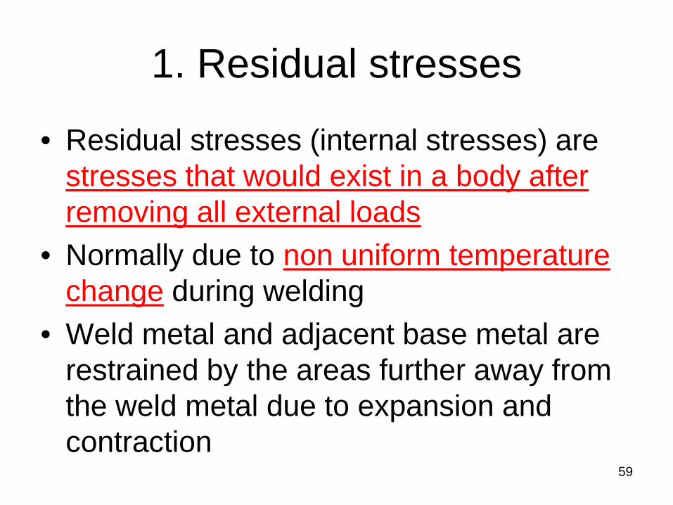
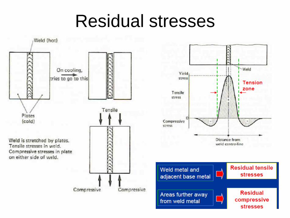
• Residual stresses (internal stresses) are stresses that would exist in a body after removing all external loads
• Normally due to non uniform temperature change during welding
• Weld metal and adjacent base metal are restrained by the areas further away from the weld metal due to expansion and contraction
59
60
Residual stresses
Changes in temperature and stresses during welding
61
Wel
d di
rect
ion
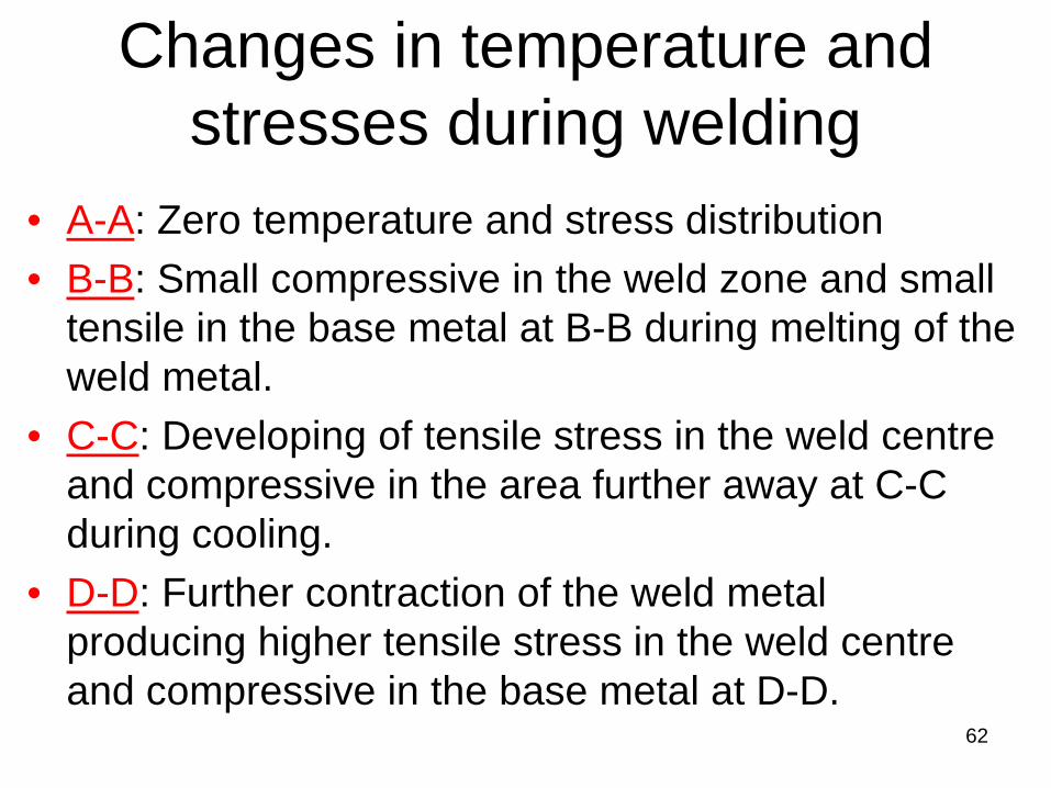
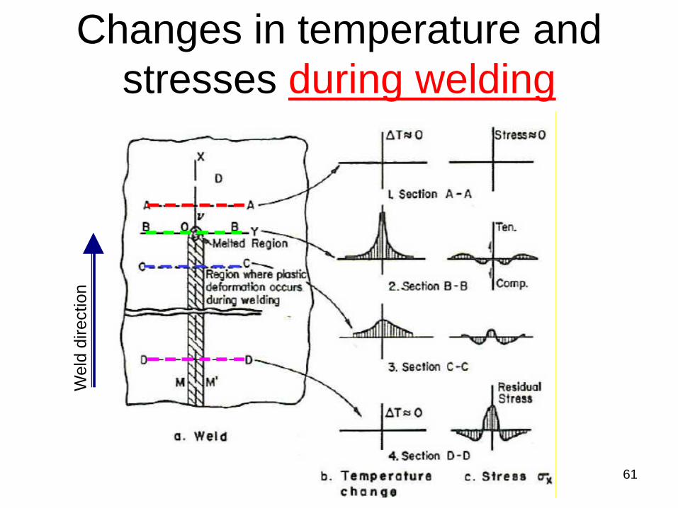
• A-A: Zero temperature and stress distribution • B-B: Small compressive in the weld zone and small
tensile in the base metal at B-B during melting of the weld metal.
• C-C: Developing of tensile stress in the weld centre and compressive in the area further away at C-C during cooling.
• D-D: Further contraction of the weld metal producing higher tensile stress in the weld centre and compressive in the base metal at D-D.
62
Changes in temperature and stresses during welding
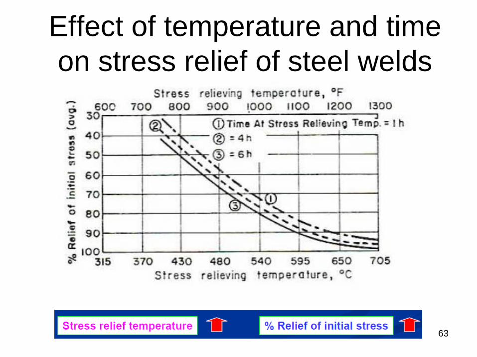
Effect of temperature and time on stress relief of steel welds
63
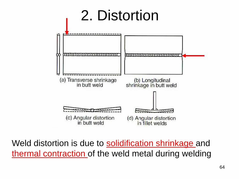
2. Distortion
64
Weld distortion is due to solidification shrinkage and thermal contraction of the weld metal during welding
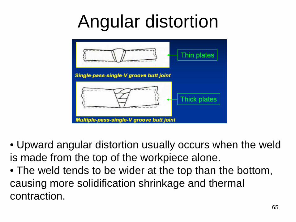
Angular distortion
65
• Upward angular distortion usually occurs when the weld is made from the top of the workpiece alone. • The weld tends to be wider at the top than the bottom, causing more solidification shrinkage and thermal contraction.
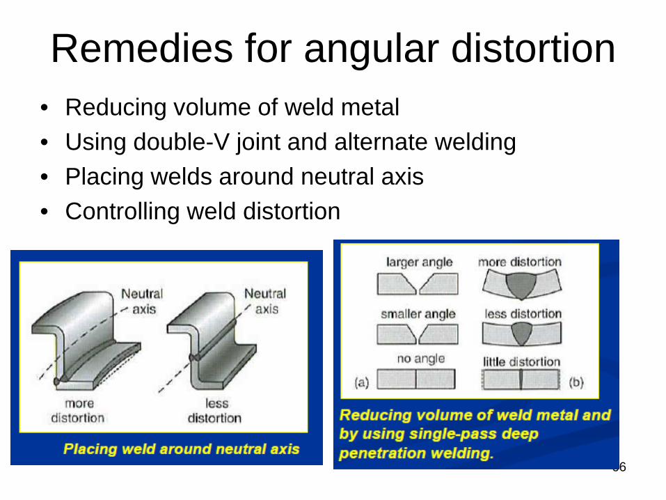
Remedies for angular distortion • Reducing volume of weld metal • Using double-V joint and alternate welding • Placing welds around neutral axis • Controlling weld distortion
66
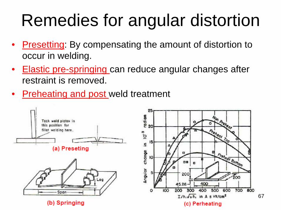
Remedies for angular distortion • Presetting: By compensating the amount of distortion to
occur in welding. • Elastic pre-springing can reduce angular changes after
restraint is removed. • Preheating and post weld treatment
67
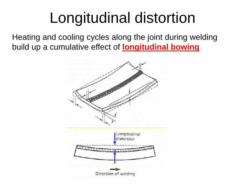
Longitudinal distortion Heating and cooling cycles along the joint during welding build up a cumulative effect of longitudinal bowing
Remedies for Longitudinal distortion
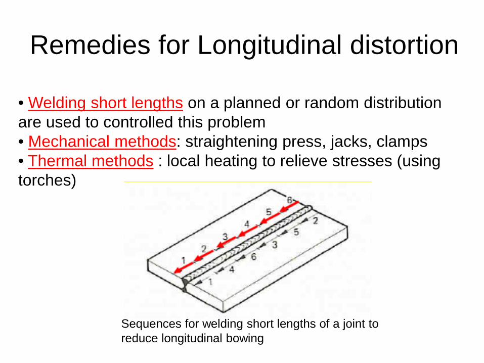
Sequences for welding short lengths of a joint to reduce longitudinal bowing
• Welding short lengths on a planned or random distribution are used to controlled this problem • Mechanical methods: straightening press, jacks, clamps • Thermal methods : local heating to relieve stresses (using torches)
Defects & Discontinuity • Defect: A flaw or flaws that by nature or
accumulated effect render a part or product unable to meet minimum applicable acceptance standards
• Defect: The term designates rejectability • Discontinuity: An interruption of the typical
structure of a material, such as a lack of homogeneity in its mechanical, metallurgical, or physical characteristics.
• A discontinuity is not necessarily a defect
70
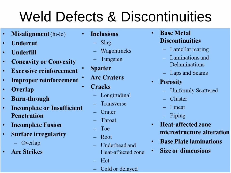
Weld Defects & Discontinuities
71
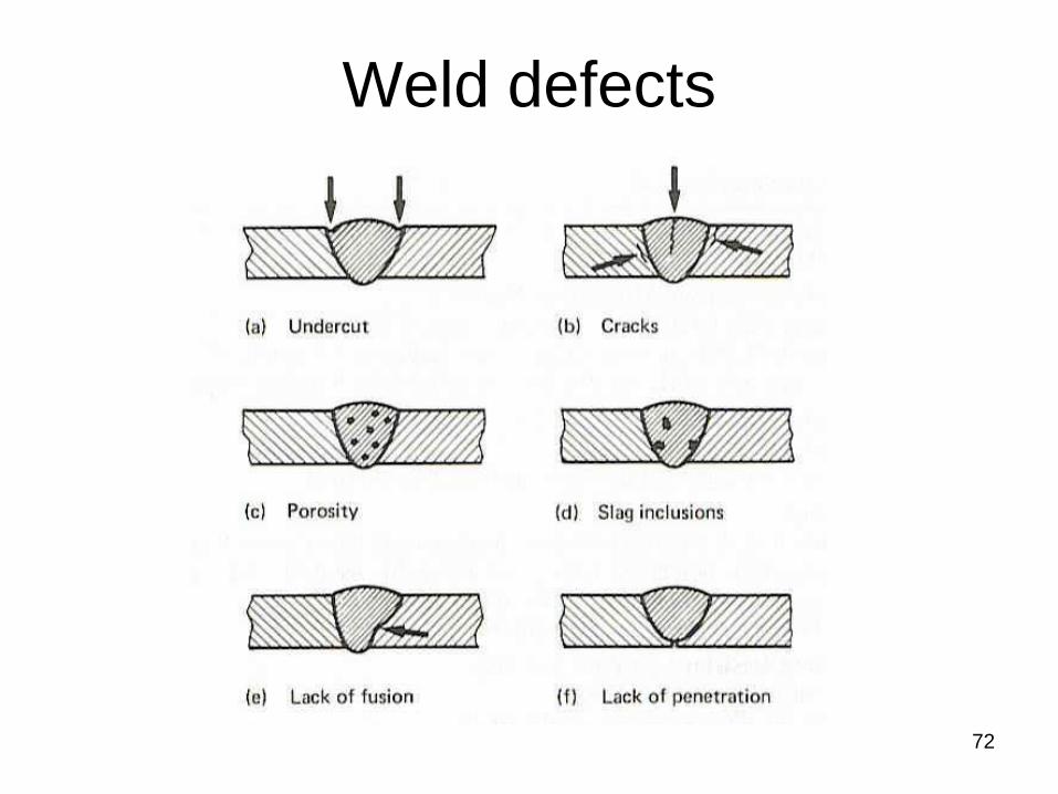
Weld defects
72

73
Mis-alignment
• Amount a joint is out of alignment at the root
• Cause: Transition thickness, carelessness
• Prevention-workmanship • Repair- Grinding
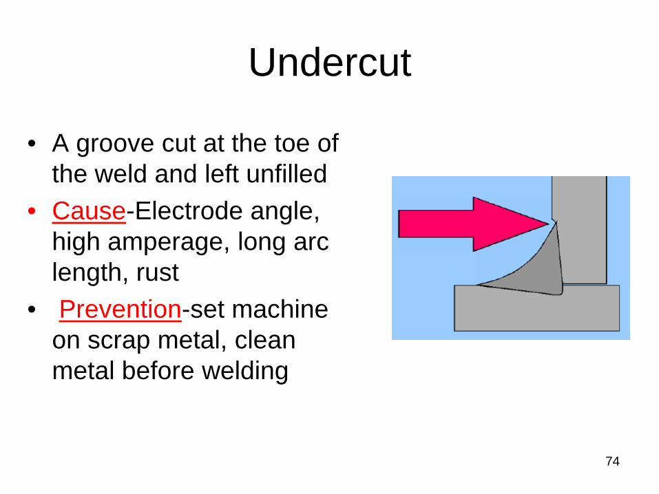
Undercut
• A groove cut at the toe of the weld and left unfilled
• Cause-Electrode angle, high amperage, long arc length, rust
• Prevention-set machine on scrap metal, clean metal before welding
74
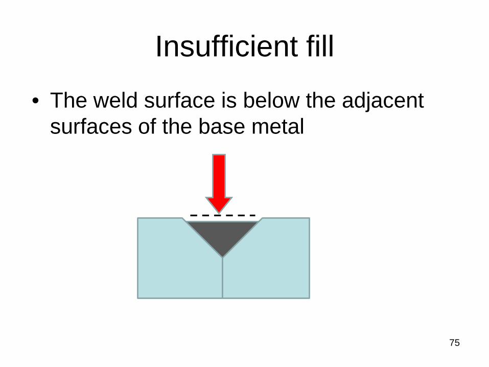
Insufficient fill
• The weld surface is below the adjacent surfaces of the base metal
75
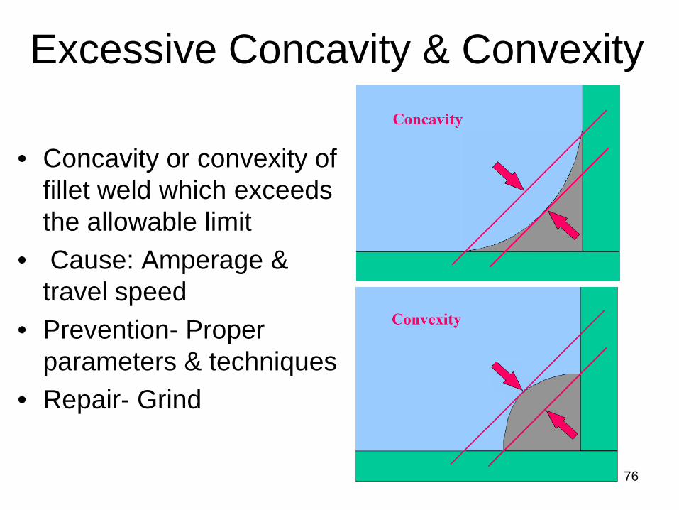
• Concavity or convexity of fillet weld which exceeds the allowable limit
• Cause: Amperage & travel speed
• Prevention- Proper parameters & techniques
• Repair- Grind
76
Excessive Concavity & Convexity
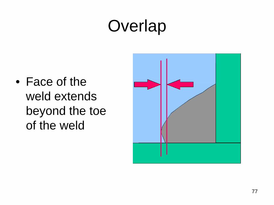
Overlap
• Face of the weld extends beyond the toe of the weld
77
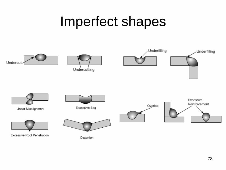
Imperfect shapes
78

Burn through
• Undesirable open hole – completely melted through base metal
• May or maynot left open • Cause- excessive heat input • Prevention-reduce heat input
by adjusting parameters • Repair- Filling
79
80
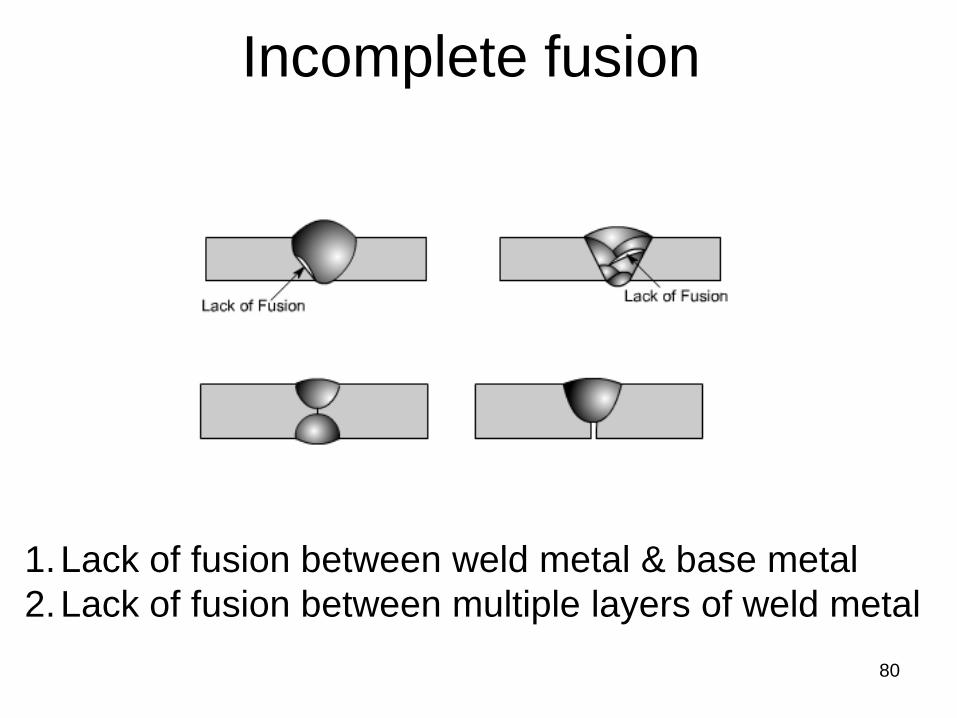
Incomplete fusion
1.Lack of fusion between weld metal & base metal 2.Lack of fusion between multiple layers of weld metal
Incomplete fusion
• Weld metal does not form a cohesive bond with the base metal
• Cause- low amperage, steep electrode angles, fast ravel speed, lack of preheat etc.
• Prevention- eliminate potential causes • Repair- remove & reweld
81
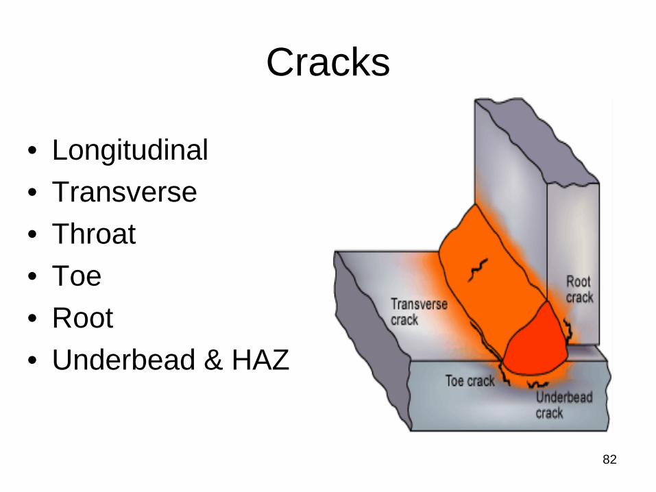
Cracks
82
• Longitudinal • Transverse • Throat • Toe • Root • Underbead & HAZ
Metallurgical defects
83
84
Gas metal reactions
• Metals react with almost any gas except the noble or inert gases
• Gases, including N2, O2 & H2, dissolve in liquids, including molten metals.
• Gas molecules (or atoms or ions) occupy the many rather large spaces between atoms of the metal in liquid form

85
Gas Dissolution and Solublllty In Molten Metal
• The amount of N2, O2 & H2 that can dissolve in molten metal almost always increases with increasing temp. of the liquid
• Also a function of the partial pressure of the gas species above the liquid.
• This is expressed by Sievert’s law:
86
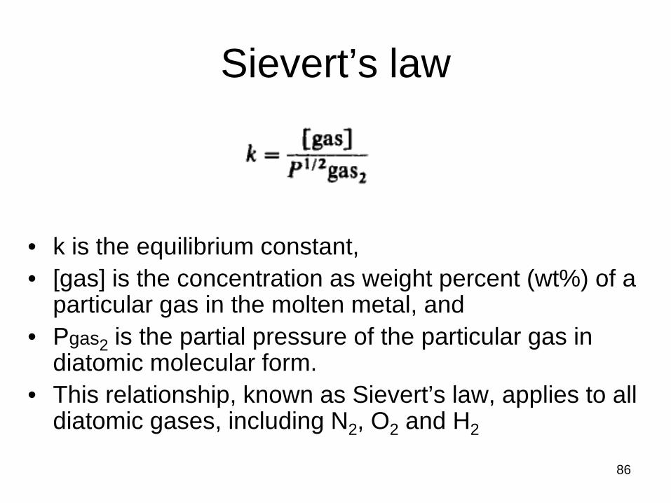
Sievert’s law
• k is the equilibrium constant, • [gas] is the concentration as weight percent (wt%) of a
particular gas in the molten metal, and • Pgas2 is the partial pressure of the particular gas in
diatomic molecular form. • This relationship, known as Sievert’s law, applies to all
diatomic gases, including N2, O2 and H2
87
Gas Dissolution and Solublllty In Molten Metal
• Once dissolved in molten metal, gases like N2, O2 and H2 can lead to one or more of several things: – they can remain in solution to cause hardening; – they can remain in solution and stabilize a particular
phase – they can be rejected from the melt upon
solidification (presuming solubility decreases, as it often does) to produce porosity
– they can lead to formation of brittle compounds
Gas Dissolution & Solid solution hardening
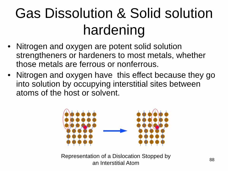
88 Representation of a Dislocation Stopped by
an Interstitial Atom
• Nitrogen and oxygen are potent solid solution strengtheners or hardeners to most metals, whether those metals are ferrous or nonferrous.
• Nitrogen and oxygen have this effect because they go into solution by occupying interstitial sites between atoms of the host or solvent.
89
Solid Solution Hardening and Phase Stabillzatlon
• As small as the atoms of these gases are, they are still too large to fit into interstices without causing fairly substantial distortion of bonds and storing of energy.
• As a result, they increase strength by resisting the motion of dislocations by the repulsion between the strain field they produce and the strain field of dislocations trying to move in response to an applied stress.
• The effectiveness of nitrogen as a strengthening addition is comparable to carbon in iron.
• Unfortunately, increased strength and hardness comes at the expense of ductility and toughness
90
Porosity Formation • Beyond some limit (the solubility limit), every
molten metal oust as every liquid) will be unable to dissolve any more of a particular gas.
• Furthermore, that solubility limit in the molten metal usually decreases with decreasing temperature, until at the melting point, upon solidification, the solubility drops precipitously.
Porosity Formation
91
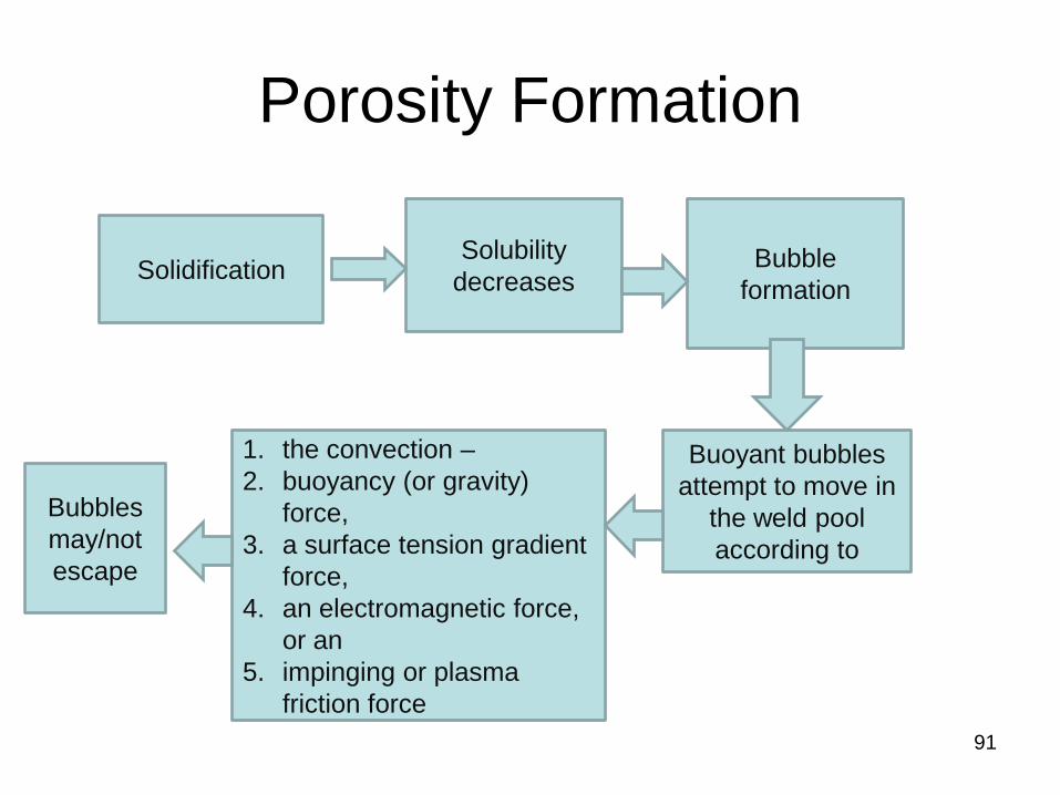
Solidification Solubility
decreases Bubble
formation
Buoyant bubbles attempt to move in
the weld pool according to
1. the convection – 2. buoyancy (or gravity)
force, 3. a surface tension gradient
force, 4. an electromagnetic force,
or an 5. impinging or plasma
friction force
Bubbles may/not escape

92
Porosity → Problems • First, it indicates that shielding was less than
adequate, and that unwanted gas-metal reactions are occurring.
• Second, pores can easily act as stress risers, thereby promoting brittle (over ductile) fracture and aggravating susceptibility to cyclic loading (fatigue). – The fact that a pore can act to arrest a propagating crack
by blunting it, and, thereby, reducing the stress at its tip, is not justification for accepting porosity. Unless every pore is intentionally introduced and controlled in size and location (which is absurd!),
• Third, Porosity indicates that the process is not under proper control
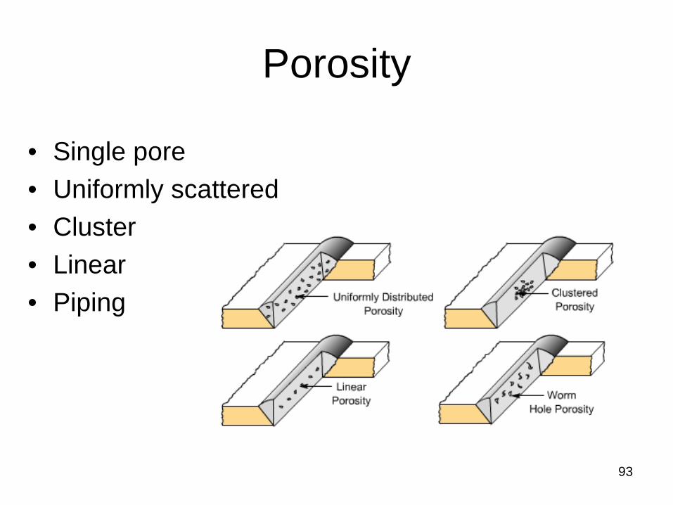
Porosity
• Single pore • Uniformly scattered • Cluster • Linear • Piping
93
Embrittlement Reactions
94
N2, O2, H2
Nitrides
Examples 1. Fe2N in Fe based alloys
which reduce ductility and impact toughness.
2. AlN in Al containing steels → Hardness
Oxides
Examples 1. Fe2O3, 2. Al2O3, 3. SiO2
Hydrides
Examples 1. TiH2 causing
embrittlement
95
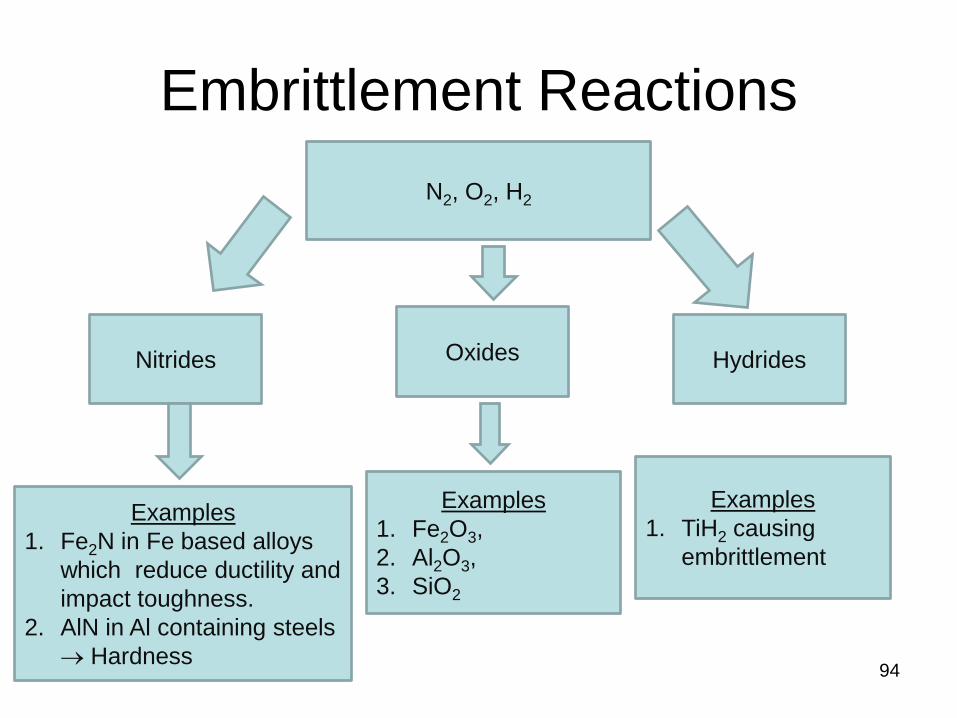
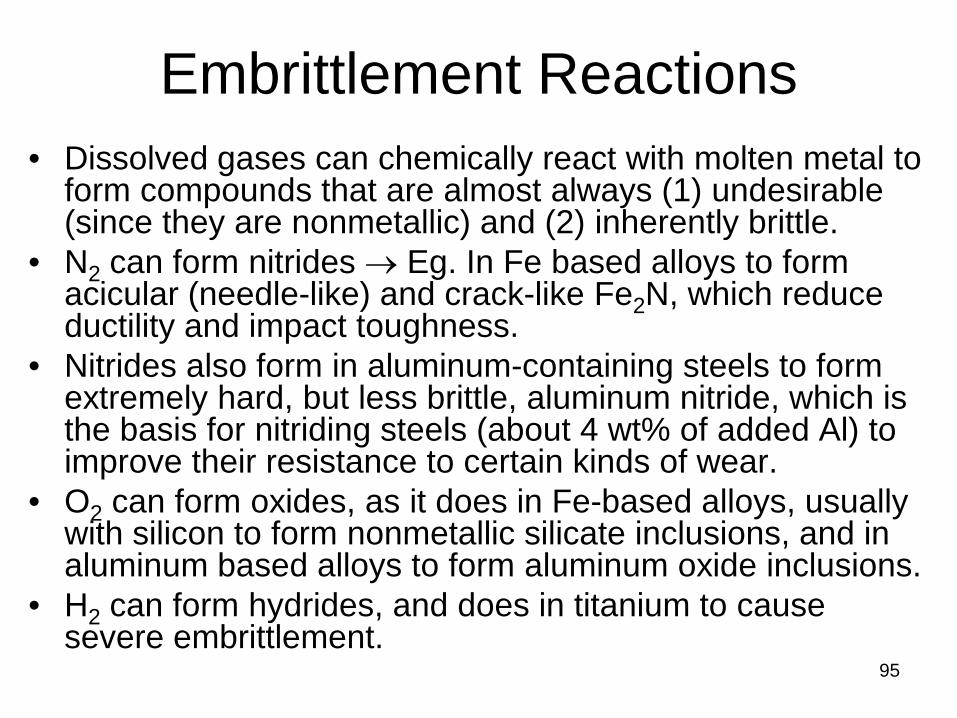
Embrittlement Reactions • Dissolved gases can chemically react with molten metal to
form compounds that are almost always (1) undesirable (since they are nonmetallic) and (2) inherently brittle.
• N2 can form nitrides → Eg. In Fe based alloys to form acicular (needle-like) and crack-like Fe2N, which reduce ductility and impact toughness.
• Nitrides also form in aluminum-containing steels to form extremely hard, but less brittle, aluminum nitride, which is the basis for nitriding steels (about 4 wt% of added Al) to improve their resistance to certain kinds of wear.
• O2 can form oxides, as it does in Fe-based alloys, usually with silicon to form nonmetallic silicate inclusions, and in aluminum based alloys to form aluminum oxide inclusions.
• H2 can form hydrides, and does in titanium to cause severe embrittlement.

96
Hydrogen Effects
• Hydrogen is one of four or five elements (H, C, N, B, and, possibly, O) with a sufficiently small atomic diameter to dissolve interstitially in most metals.
• The introduction of hydrogen into construction steels has three major deleterious effects: – (1) Hydrogen embrittlement, – (2) Hydrogen porosity, and – (3) Hydrogen cracking
97
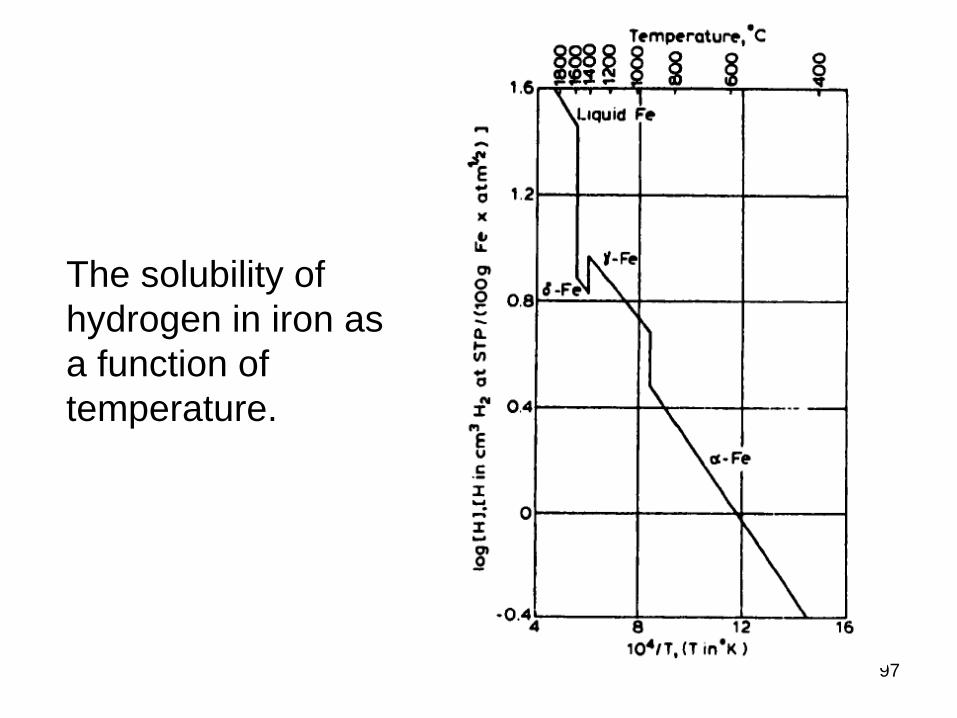
The solubility of hydrogen in iron as a function of temperature.
98
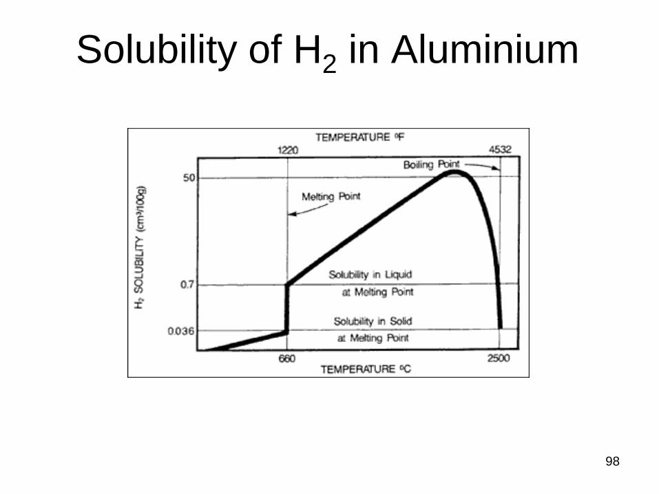
Solubility of H2 in Aluminium

99
Hydrogen Cracking
Hydrogen Cracking
100
Pre-existing defects, cracks
Localized regions of biaxial or tri-
axial stress concentration
Residual or applied stresses
Hydrogen diffuses preferentially to these sites because of the lattice expansion that
exists
As the local H2 concentration increases, the cohesive
energy and strength of the lattice decrease
101
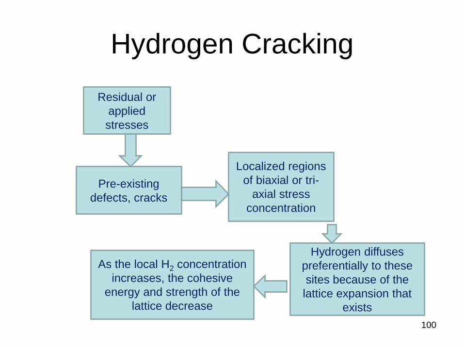
Hydrogen Cracking • Preferred models involve the presence of pre-existing
defect sites in the material, including small cracks or discontinuities caused by minor phase particles or inclusions.
• In the presence of residual or applied stresses, such sites may develop highly localized regions of biaxial or tri-axial stress concentration.
• Hydrogen diffuses preferentially to these sites because of the lattice expansion that exists.
• As the local hydrogen concentration increases, the cohesive energy and strength of the lattice decrease.
• When the cohesive strength falls below the local intensified stress level, spontaneous fracture occurs. Additional hydrogen then evolves in the crack volume, and the process is repeated.