Embed Size (px)
Citation preview

INSTALLATION, OPERATION, AND MAINTENANCE MANUAL
WELKER® HEATED GAS SAMPLER
MODELHGS DRAWING NUMBERSAD590DEAD590DE.1AD590DG.1AD590DG.2 MANUAL NUMBERIOM-095 REVISIONRev. B, 9/28/2016

TABLE OF CONTENTS
2 IOM-095 MODEL: HGS REV: B 13839 West Bellfort Street, Sugar Land, TX 77498 welker.com Service Department 281.491.2331
Welker®, Welker Jet®, WelkerScope®, and OdorEyes® are Registered Trademarks owned by Welker, Inc.
SAFETY 3
1. PRODUCT INFORMATION 4
1.1 Introduction 4
1.2 Product Description 4
1.3 Specifications 5
1.4 Equipment Diagrams 6
2. INSTALLATION & OPERATION 15
2.1 Before You Begin 15
2.2 Principles of Operation 15
2.3 Installation 16
2.4 Sampling 20
3. MAINTENANCE 21
3.1 Before You Begin 21
3.2 Maintenance 22
3.3 Troubleshooting 23
APPENDIX 24
A: Referenced or Attached Documents 24

IMPORTANT SAFETY INFORMATIONREAD ALL INSTRUCTIONS
Notes emphasize information and/or provide additional information to assist the user.
Caution messages appear before procedures that could result in damage to equipment if not observed.
Warning messages appear before procedures that could result in personal injury if not observed.
This manual is intended to be used as a basic installation and operation guide for the Welker® Heated Gas Sampler, HGS. For comprehensive instructions, please refer to the IOM Manuals for each individual component. A list of relevant component IOM Manuals is provided in Appendix A of this manual.
The information in this manual has been carefully checked for accuracy and is intended to be used as a guide for the installation, operation, and maintenance of the Welker® equipment described in this manual. Correct installation and operation, however, are the responsibility of the end user. Welker reserves the right to make changes to this manual and all products in order to improve performance and reliability.
BEFORE YOU BEGIN
Read these instructions completely and carefully.
IMPORTANT - Save these instructions for local inspector's use.
IMPORTANT - Observe all governing codes and ordinances.
Note to Installer - Leave these instructions with the end user.
Note to End User - Keep these instructions for future reference.
Installation of this Heated Gas Sampler is of a mechanical and electrical nature.
Proper installation is the responsibility of the installer. Product failure due to improper installation is not covered under the warranty.
If you received a damaged Heated Gas Sampler, please contact a Welker® representative immediately.
Phone: 281.491.2331Address: 13839 West Bellfort Street
Sugar Land, TX 77498
SAFETY
3 IOM-095 MODEL: HGS REV: B 13839 West Bellfort Street, Sugar Land, TX 77498 welker.com Service Department 281.491.2331

1.1 Introduction
We appreciate your business and your choice of Welker® products. The installation, operation, and maintenance liability for this equipment becomes that of the purchaser at the time of receipt. Reading the applicable Installation, Operation, and Maintenance (IOM) Manuals prior to installation and operation of this equipment is required for a full understanding of its application and performance prior to use.*
If you have any questions, please call Welker at 1-281-491-2331.
*The following procedures have been written for use with standard Welker® parts and equipment. Assemblies that have been modified may have additional
requirements and specifications that are not listed in this manual.
1.2 Product Description
The Welker® HGS Heated Gas Sampler is designed to heat sample equipment to ensure the sampled gas remains above the hydrocarbon dew point, preventing phase change and thus preserving the representativeness of the sample.
The HGS consists of a sampler subassembly and a heater subassembly inside an insulated enclosure. At the heart of the sampler subassembly is the Welker® MPS-2 Gas Sampler, which is actuated by a solenoid. The solenoid can be operated by a Welker® 6Tc Timer/Controller or customer-supplied Programmable Logic Controller (PLC) to sample proportional to flow. The primary components of the heater assembly are the thermostat and heater. An operator sets the thermostat to the desired temperature, and the heater heats the enclosure by convection to maintain the desired internal temperature, which can be verified on site by referring to the temperature gauge on the enclosure exterior. The pipeline-mounted enclosure ensures the internal heat transfer limits the effects of ambient conditions on the sample. The enclosure mounting bracket accommodates multiple pipeline sizes and enables the HGS to be mounted parallel or perpendicular to the pipeline. The modular design of the HGS allows the interior subassemblies to be rearranged to ease installation and removal for maintenance.
For this manual, the term "PLC," or Programmable Logic Controller, will be used to refer to the PLC, DCS, or other signal control
system used by the customer to activate and operate the solenoid.
Welker may custom design the HGS to suit the particular application and specifications of each customer.
SECTION 1: PRODUCT INFORMATION
4 IOM-095 MODEL: HGS REV: B 13839 West Bellfort Street, Sugar Land, TX 77498 welker.com Service Department 281.491.2331

1.3 Specifications
The specifications listed in this section are generalized for this equipment. Welker can modify the equipment according to your
company's needs. Please note that the specifications may vary depending on the customizations of your
equipment.
Table 1: HGS SpecificationsProducts Sampled Gases Compatible With the Materials of Construction
Materials of Construction316/316L Stainless Steel Wetted Parts, Anodized Aluminum Non-Wetted Parts, Carbon Steel, Polyester/Propylene (Enclosure), PTFE, Teflon®, and Viton®
Maximum Allowable Operating Pressure 1440 psig @ -20 °F to 120 °F (99 barg @ -28 °C to 48 °C)
ConnectionsActuation: ¼" FNPTProduct Inlet: ¹⁄₈" FNPTRelief Outlet: ¼" FNPT
Utility Requirements Pneumatic: 65–70 psig (4.4–4.8 barg)
Electrical Connections Electric Heater: AC 110 VSolenoid: DC 12 V or DC 24 V
Sample Volume 0.25 cc
Container Volume 300 cc500 cc
Operation MPS-2: Piston-OperatedMounting Parallel or Perpendicular to Pipeline
Features
Catalytic or Electric Heater With ThermostatInsulated Enclosure With External Temperature GaugeWelker® IR-7 Instrument RegulatorWelker® MPS-2 Gas Sampler
Options
3-Way SolenoidWelker® 6Tc Timer/ControllerWelker® CP-2 Constant Pressure CylinderWelker® FilterWelker® SC Single Cavity Sample Cylinder
5 IOM-095 MODEL: HGS REV: B 13839 West Bellfort Street, Sugar Land, TX 77498 welker.com Service Department 281.491.2331

1.4 Equipment Diagrams
Figure 1: Standard HGS Connections Diagram
6 IOM-095 MODEL: HGS REV: B 13839 West Bellfort Street, Sugar Land, TX 77498 welker.com Service Department 281.491.2331
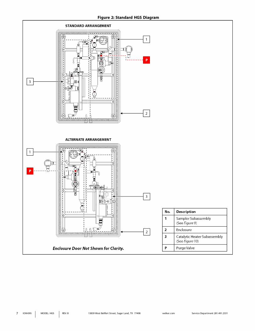
Figure 2: Standard HGS Diagram
7 IOM-095 MODEL: HGS REV: B 13839 West Bellfort Street, Sugar Land, TX 77498 welker.com Service Department 281.491.2331

Figure 3: HGS With Welker® 6Tc Connections Diagram
8 IOM-095 MODEL: HGS REV: B 13839 West Bellfort Street, Sugar Land, TX 77498 welker.com Service Department 281.491.2331

Figure 4: HGS With Welker® 6Tc Diagram
9 IOM-095 MODEL: HGS REV: B 13839 West Bellfort Street, Sugar Land, TX 77498 welker.com Service Department 281.491.2331

Figure 5: HGS With Electric Heater Connections Diagram
Figure 6: HGS With Electric Heater Diagram
10 IOM-095 MODEL: HGS REV: B 13839 West Bellfort Street, Sugar Land, TX 77498 welker.com Service Department 281.491.2331
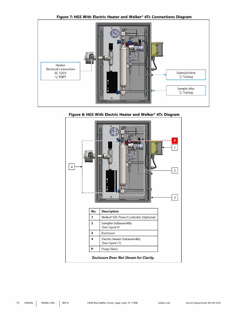
Figure 7: HGS With Electric Heater and Welker® 6Tc Connections Diagram
Figure 8: HGS With Electric Heater and Welker® 6Tc Diagram
11 IOM-095 MODEL: HGS REV: B 13839 West Bellfort Street, Sugar Land, TX 77498 welker.com Service Department 281.491.2331

Figure 9: Sampler Subassembly Diagram
12 IOM-095 MODEL: HGS REV: B 13839 West Bellfort Street, Sugar Land, TX 77498 welker.com Service Department 281.491.2331

Figure 10: Catalytic Heater Subassembly Diagram
13 IOM-095 MODEL: HGS REV: B 13839 West Bellfort Street, Sugar Land, TX 77498 welker.com Service Department 281.491.2331

Figure 11: Electric Heater Subassembly Diagram
14 IOM-095 MODEL: HGS REV: B 13839 West Bellfort Street, Sugar Land, TX 77498 welker.com Service Department 281.491.2331
2.1 Before You Begin
After unpacking the unit, check the equipment for compliance and any damage that may have occurred during shipment.
Immediately contact a Welker® representative if you received damaged equipment.
When sealing fittings with PTFE tape, refer to the proper sealing instructions for the brand used.
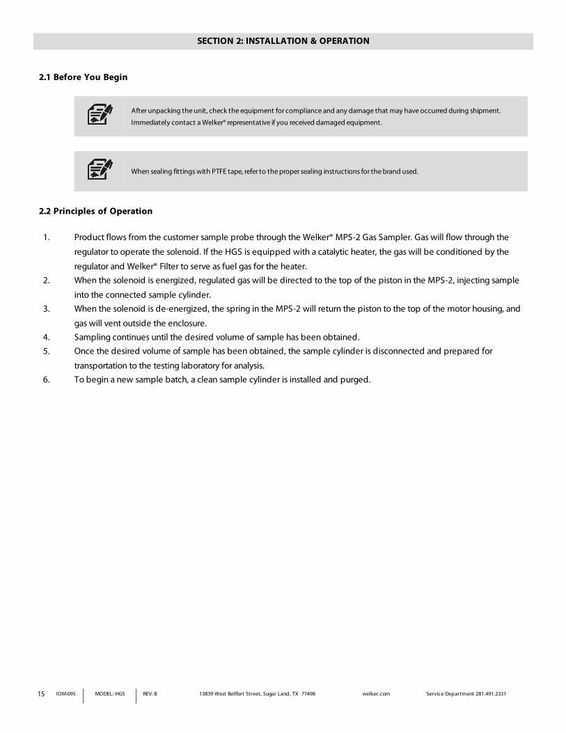
2.2 Principles of Operation
1. Product flows from the customer sample probe through the Welker® MPS-2 Gas Sampler. Gas will flow through the
regulator to operate the solenoid. If the HGS is equipped with a catalytic heater, the gas will be conditioned by the
regulator and Welker® Filter to serve as fuel gas for the heater. 2. When the solenoid is energized, regulated gas will be directed to the top of the piston in the MPS-2, injecting sample
into the connected sample cylinder. 3. When the solenoid is de-energized, the spring in the MPS-2 will return the piston to the top of the motor housing, and
gas will vent outside the enclosure. 4. Sampling continues until the desired volume of sample has been obtained. 5. Once the desired volume of sample has been obtained, the sample cylinder is disconnected and prepared for
transportation to the testing laboratory for analysis. 6. To begin a new sample batch, a clean sample cylinder is installed and purged.
SECTION 2: INSTALLATION & OPERATION
15 IOM-095 MODEL: HGS REV: B 13839 West Bellfort Street, Sugar Land, TX 77498 welker.com Service Department 281.491.2331

2.3 Installation
At least two (2) people are required to correctly and safely install the enclosure to the pipeline.
1. Unlatch both sides of the enclosure door, and then remove the front of the enclosure.
2. Ensure that all valves are closed.
3. Determine if the enclosure is to be installed parallel or perpendicular to the pipeline (Figure 12).
Figure 12: Pipeline Mounting Options
4. Determine if the enclosure will be installed over one (1) or more threaded connections on the customer pipeline or
adjacent to the sample point. 5. If the enclosure will be installed over one (1) threaded connection (i.e., the sample probe), continue to step 6. If the
enclosure will be installed over multiple threaded connections, proceed to step 9. If the enclosure will be installed adjacent to the sample point, proceed to step 22.
Installing the Enclosure Over One (1) Threaded Connection
6. Locate the mounting bracket over the threaded connection parallel or perpendicular to the pipeline as determined by the customer.
7. Set the appropriate hole in the bottom of the enclosure over the desired threaded connection (i.e., the sample probe) on the customer pipeline. The enclosure should rest in the mounting bracket.
8. Proceed to step 24.
16 IOM-095 MODEL: HGS REV: B 13839 West Bellfort Street, Sugar Land, TX 77498 welker.com Service Department 281.491.2331

Installing the Enclosure Over Multiple Threaded Connections
If the enclosure will be mounted over multiple threaded connections, it may be necessary to rearrange the sampler and heater
subassemblies inside the enclosure to ensure there is room for customer equipment.
9. Locate the mounting bracket over the threaded connections parallel or perpendicular to the pipeline as determined by
the customer. 10. Determine whether the subassemblies inside the enclosure need to be rearranged in order to accommodate customer
equipment. If the subassemblies need to be rearranged, continue to step 11. If the subassemblies do not need to be rearranged, set the appropriate holes in the bottom of the enclosure over the desired threaded connections on the customer pipeline, and then proceed to step 24.
Rearranging Subassemblies Inside the Enclosure
11. Loosen the t-bolts connecting the heater subassembly to the enclosure, and then pull the bracket off the track.
12. Remove the heater subassembly and set it aside.
13. Remove the conduit extension attached to the solenoid conduit and set it aside.
14. Loosen the t-bolts connecting the sampler subassembly to the enclosure, and then slide the sampler subassembly to the other side of the enclosure.
15. Tighten the t-bolts to secure the sampler assembly inside the enclosure.
16. Rotate the conduit outlet on the solenoid so it faces the opposite direction.
17. Install the conduit extension to the solenoid conduit.
18. Install the heater subassembly to the track on the other side of the enclosure.
19. Tighten the t-bolts to secure the heater subassembly inside the enclosure.
20. Set the appropriate holes in the bottom of the enclosure over the desired threaded connections on the customer pipeline. The enclosure should rest in the mounting bracket.
21. Proceed to step 24.
Installing the Enclosure Adjacent to the Sample Point
22. Locate the mounting bracket as close to the sample point as possible. The mounting bracket can be parallel or perpendicular to the pipeline as determined by the customer.
23. Continue to step 24.
17 IOM-095 MODEL: HGS REV: B 13839 West Bellfort Street, Sugar Land, TX 77498 welker.com Service Department 281.491.2331

Completing Installation
24. Secure the mounting bracket to the pipeline using the provided brackets, washers, nuts, and bolts (Figure 12).
25. Install the customer-supplied sample probe to the pipeline.
Welker recommends that the probe be installed in the top of the pipe and inserted into the center one-third (¹⁄₃) of the pipeline
in a location where the product is well-mixed and will yield an accurate and representative sample. The sample probe should be
located in the least turbulent area of the flowing stream available (i.e., not in a header or blow-down stack and away from
obstructions, elbows, and partially closed valves).
26. Using customer-supplied tubing with a minimum diameter of ¼", connect from the probe outlet to the product inlet
(Figure 9).
If the enclosure is mounted adjacent to the sample point, Welker recommends that the tubing from the sample outlet on the
probe to the sample inlet on the enclosure be heat-traced.
27. If desired, use customer-supplied ¼" tubing to connect from the solenoid vent to flare (Figure 5 or Figure 7).
28. Connect an appropriate power supply to the heater (Figure 10 or Figure 13). The catalytic heater should be connected to the power starter source.
The electric heater will be HOT once power is supplied. DO NOT touch the heater.
Figure 13: Electric Heater Wiring Diagram
29. As necessary, connect an appropriate power supply from the PLC to the solenoid (Figure 14).
18 IOM-095 MODEL: HGS REV: B 13839 West Bellfort Street, Sugar Land, TX 77498 welker.com Service Department 281.491.2331
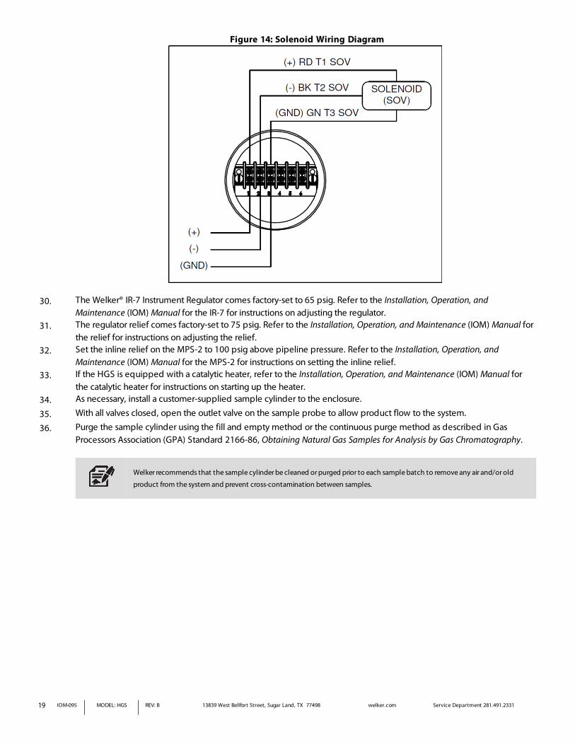
Figure 14: Solenoid Wiring Diagram
30. The Welker® IR-7 Instrument Regulator comes factory-set to 65 psig. Refer to the Installation, Operation, and
Maintenance (IOM) Manual for the IR-7 for instructions on adjusting the regulator. 31. The regulator relief comes factory-set to 75 psig. Refer to the Installation, Operation, and Maintenance (IOM) Manual for
the relief for instructions on adjusting the relief. 32. Set the inline relief on the MPS-2 to 100 psig above pipeline pressure. Refer to the Installation, Operation, and
Maintenance (IOM) Manual for the MPS-2 for instructions on setting the inline relief. 33. If the HGS is equipped with a catalytic heater, refer to the Installation, Operation, and Maintenance (IOM) Manual for
the catalytic heater for instructions on starting up the heater. 34. As necessary, install a customer-supplied sample cylinder to the enclosure.
35. With all valves closed, open the outlet valve on the sample probe to allow product flow to the system.
36. Purge the sample cylinder using the fill and empty method or the continuous purge method as described in Gas Processors Association (GPA) Standard 2166-86, Obtaining Natural Gas Samples for Analysis by Gas Chromatography.
Welker recommends that the sample cylinder be cleaned or purged prior to each sample batch to remove any air and/or old
product from the system and prevent cross-contamination between samples.
19 IOM-095 MODEL: HGS REV: B 13839 West Bellfort Street, Sugar Land, TX 77498 welker.com Service Department 281.491.2331

2.4 Sampling
1. After the sample cylinder has been purged, close purge valve P (Figure 9). 2. Allow pressure to bleed until the pressure gauge on the sample cylinder reads 0 psig. 3. Close the bottom valve on the sample cylinder. The top valve on the sample cylinder must remain open. 4. Return the enclosure door to the front of the enclosure, and then secure the door to the enclosure using the latches. 5. As necessary, program the Welker® 6Tc Timer/Controller (Figure 4 or Figure 8). Refer to the Installation, Operation, and
Maintenance (IOM) Manual for the 6Tc for instructions on setting the 6Tc to sample proportional to flow. 6. As necessary, set the PLC to the desired proportional to flow sampling frequency based on the equations provided
(Figure 15).
Figure 15: Sampling Frequency Equations
7. Continue sampling until the desired volume of sample has been obtained.
The pressure gauge on the sample cylinder will read pipeline pressure when the cylinder is full.
If the sample cylinder continues to collect sample after reaching pipeline pressure, the cylinder pressure will increase.
8. Unlatch both sides of the enclosure door, and then remove the front of the enclosure. 9. Close the top valve on the sample cylinder.
10. Remove the sample cylinder from the HGS, and then tag it and prepare it for transportation to the testing laboratory in
accordance with company policy. 11. Install a clean sample cylinder in its place. 12. Prior to beginning a new sample batch, the sample cylinder must be purged. Purge the sample cylinder using the fill
and empty method or the continuous purge method as described in Gas Processors Association (GPA) Standard 2166-
86, Obtaining Natural Gas Samples for Analysis by Gas Chromatography.
Welker recommends that the sample cylinder be cleaned or purged prior to each sample batch to remove any air and/or old
product from the system and prevent cross-contamination between samples.
20 IOM-095 MODEL: HGS REV: B 13839 West Bellfort Street, Sugar Land, TX 77498 welker.com Service Department 281.491.2331

3.1 Before You Begin
1. Welker recommends that the unit have standard maintenance every six (6) months under normal
operating conditions. In cases of severe service, dirty conditions, excessive usage, or other unique applications that
may lead to excess wear on the unit, a more frequent maintenance schedule may be appropriate. 2. Prior to maintenance or disassembly of the unit, it is advisable to have a repair kit available for repairs of the system in
case of unexpected wear or faulty seals.
New seals supplied in spare parts kits should be lightly lubricated before being installed to ease the installation of the seals and
reduce the risk of damage when positioning them on parts. Wipe excess lubricant from the seals, as it may adversely affect
analytical instrument results.
For sample-exposed seals, Welker recommends non-hydrocarbon-based lubricants, such as Krytox®.
For non-sample-exposed seals, Welker recommends either non-hydrocarbon-based lubricants or silicone-based lubricants, such
as Molykote® 111.
After the seals are installed, the outer diameter of shafts and inner diameter of cylinders may be lubricated to allow smooth
transition of parts.
3. All maintenance and cleaning of the unit should be performed on a smooth, clean surface. 4. Welker recommends having the following tools available for maintenance. Please note that the exact tools required may
vary by model. a. Adjustable Wrench (Qty. 2) b. Channel Lock Pliers c. Hex Key Set d. Seal Pick
SECTION 3: MAINTENANCE
21 IOM-095 MODEL: HGS REV: B 13839 West Bellfort Street, Sugar Land, TX 77498 welker.com Service Department 281.491.2331

22 IOM-095 MODEL: HGS REV: B 13839 West Bellfort Street, Sugar Land, TX 77498 welker.com Service Department 281.491.2331
3.2 Maintenance
1. During system operation, monitor the system for leaks. If leaks are present, halt operation and repair as necessary. 2. If applicable, routinely open filter drain valve D to allow moisture to drain from the filter (Figure 10). 3. Turn OFF all electrical power prior to performing maintenance.
The heater will be HOT after use. Allow approximately thirty (30) minutes for the heater to cool down prior to performing
maintenance.
4. To perform maintenance on system components:
a. Close the outlet valve on the customer sample probe. b. Depressurize the system and close all valves. c. Remove individual system components for maintenance. d. For complete and proper maintenance on individual system components, refer to the appropriate
manufacturer's Installation, Operation, and Maintenance (IOM) Manual. A list of component Installation,
Operation, and Maintenance (IOM) Manuals is available in Appendix A, Referenced or Attached Documents, in this
manual. e. After performing maintenance on component parts, reconnect all instrument tubing.
Check valves for leaks and repair as necessary during reinstallation.

23 IOM-095 MODEL: HGS REV: B 13839 West Bellfort Street, Sugar Land, TX 77498 welker.com Service Department 281.491.2331
3.3 Troubleshooting
Table 2: HGS TroubleshootingIssues Possible Causes Solutions
The sample cylinder will not fill.
The inlet valve on the sample cylinder is closed.
The outlet valve on the sample cylinder is open.
The inline relief in the MSP-2 is set too high.
Ensure that the inlet valve on the sample cylinder is open.
Ensure that the outlet valve on the sample cylinder is closed.
The inline relief should be set approximately 100 psig above pipeline operating pressure. Refer to the Installation, Operation, and Maintenance (IOM) Manual for the MPS-2 for instructions on setting the inline relief.
The sample cylinder is filling too quickly.
Purge valve P is open.
The inline relief in the MPS-2 is set too low.
Close purge valve P.
The inline relief should be set approximately 100 psig above pipeline operating pressure. Refer to the Installation, Operation, and Maintenance (IOM) Manual for the MPS-2 for instructions on setting the inline relief.
The catalytic heater will not start up.
Fuel and/or fresh air are not being provided to the catalytic heater.
Refer to the Installation, Operation, and Maintenance (IOM) Manual for the catalytic heater for troubleshooting instructions.
The catalytic heater will not stay lit.
The fuel / fresh air ratio is not correct. Refer to the Installation, Operation, and Maintenance (IOM) Manual for the catalytic heater for troubleshooting instructions.
The catalytic heater cannot maintain the set temperature.
Fuel and/or fresh air are not being provided to the catalytic heater.
Refer to the Installation, Operation, and Maintenance (IOM) Manual for the catalytic heater for troubleshooting instructions.
The electric heater is not heating up.
Electricity is not being supplied to the heater.
Ensure that the electric heater has been connected to an appropriate electrical supply and that the electrical supply is functioning.
Welker®Installation, Operation, and Maintenance (IOM) Manuals suggested for use with this unit:
l IOM-002: Welker® 6Tc Timer/Controller l IOM-033: Welker® RV-1, RV-2, RV-2CP, and RV-3 Relief Valves l IOM-044: Welker® IR-7 Instrument Regulator l IOM-046: Welker® F-4, F-5, F-19, F-23, and F-31 Filters/Dryers l IOM-056: Welker® MPS-2 Gas Sampler l IOM-105: Welker® NV-1 and NV-2 Instrument Valves l IOM-113: Welker® F-7, F-8, F-9, and F-10 Filters l IOM-146: Welker® SC Single Cavity Sample Cylinder
Other Installation, Operation, and Maintenance (IOM) Manuals suggested for use with this unit:
l Ashcroft Inc. BI Series Bi-Metal Thermometers (Welker® IOM-V235) l Becker Precision Equipment TCV Thermal Check Valve (Welker® IOM-V303) l BelGAS P912 Pressure Regulator (Welker® IOM-V304) l Catalytic Industrial Group, Inc. Bruest Catalytic Heaters (Welker® IOM-V005) l Circle Seal Controls 500 Series Adjustable Popoff & Inline Relief Valves (Welker® IOM-V178) l INTERTEC™ SL DSETHERM Self-limiting Block Heater (Welker® IOM-V316) l INTERTEC™ TS Thermostat (Welker® IOM-V105) l Invensys 777-029 Thermostat (Welker® IOM-V305) l McDaniel Control, Inc. Stainless Steel Utility Gauges R7, T7, and J7 (Welker® IOM-V274) l Norgren R83 UL Listed Pressure Regulator for Industrial Cylinder Gas (Welker® IOM-V014) l Swagelok® Filters FW, F, and TF Series (Welker® IOM-V092) l Versa Products Company, Inc. C-Series Valves (Welker® IOM-V041) l Versa Products Company, Inc. CSG-4222-LA-XX-D012 4-Way Solenoid Valves (Welker® IOM-V071) l WIKA Bourdon Tube Pressure Gauges Type 232.53 and Type 233.53 (Welker® IOM-V171)
Welker® drawings and schematics suggested for use with this unit:
l Assembly Drawing: AD590DE (Standard HGS) l Assembly Drawing: AD590DE.1 (HGS With Catalytic Heater, MPS-2, and 6Tc) l Assembly Drawing: AD590DG.1 (HGS With Electric Heater, MPS-2, and 6Tc) l Assembly Drawing: AD590DG.2 (HGS With Electric Heater and MPS-2)
APPENDIX A: REFERENCED OR ATTACHED DOCUMENTS
24 IOM-095 MODEL: HGS REV: B 13839 West Bellfort Street, Sugar Land, TX 77498 welker.com Service Department 281.491.2331

____________________________________________________________________________________________________
____________________________________________________________________________________________________
____________________________________________________________________________________________________
____________________________________________________________________________________________________
____________________________________________________________________________________________________
____________________________________________________________________________________________________
____________________________________________________________________________________________________
____________________________________________________________________________________________________
____________________________________________________________________________________________________
____________________________________________________________________________________________________
____________________________________________________________________________________________________
____________________________________________________________________________________________________
____________________________________________________________________________________________________
____________________________________________________________________________________________________
____________________________________________________________________________________________________
____________________________________________________________________________________________________
____________________________________________________________________________________________________
____________________________________________________________________________________________________
____________________________________________________________________________________________________
13839 West Bellfort StreetSugar Land, TX 77498Phone: 281.491.2331
welker.com
NOTES
25 IOM-095 MODEL: HGS REV: B 13839 West Bellfort Street, Sugar Land, TX 77498 welker.com Service Department 281.491.2331


![[Jürgen Von Hagen, Michael Welker] Money as God(BookZZ.org)](https://img.pdfslide.net/doc/110x75/563dbb18550346aa9aaa3875/juergen-von-hagen-michael-welker-money-as-godbookzzorg.jpg)