Embed Size (px)
Citation preview
WELL SUSPENSION AND ABANDONMENT GUIDELINES AND INTERPRETATION NOTES
OFFICE OF THE REGULATOR OF OIL AND GAS
OPERATIONS
CONSULTATION AND ENGAGEMENT DRAFT MAY 17, 2016
If you would like this information in another official language, contact us at (867) 767-9097
CONSULTATION AND ENGAGEMENT DRAFT
TABLE OF CONTENTS
1. INTRODUCTION ......................................................................................................... 1
2. WELL CLASSIFICATION FRAMEWORK .................................................................. 4
3. CEMENT REQUIREMENTS ...................................................................................... 6
4. GAS MIGRATION, SURFACE CASING VENT FLOW AND ANNULAR PRESSURE TESTING REQUIREMENTS ........................................................................................... 7
4A. Gas Migration ........................................................................................................ 9
4B. Surface Casing Vent Flow ................................................................................... 10
4C. Annular Pressure ................................................................................................ 11
4D. Casing Failure ..................................................................................................... 12
5. WELL SUSPENSION AND MONITORING REQUIREMENTS ................................ 13
5A – Wellhead Requirements for Suspended Wells .................................................. 15
5B – Downhole Well Suspension Requirements ....................................................... 17
5C – Gas Migration and Surface Casing Vent Flow Testing and Repair Requirements During Well Suspension ............................................................................................ 19
5D –Testing and Inspection Requirements for Suspended Wells .............................. 20
6. WELL ABANDONMENT REQUIREMENTS ............................................................. 22
6A – Downhole Abandonment Requirements ............................................................ 23
6Ai – Requirements for Abandonment of Non Oil and Gas Wells .......................... 27
6B – Groundwater Protection Requirements ............................................................. 28
6C – Requirements for Locating Cement Plugs ......................................................... 29
6D – Gas Migration, Surface Casing Vent Flow and Annular Pressure Testing and Repair Requirements during Well Abandonment ....................................................... 30
6E – Surface Abandonment Requirements ............................................................... 31
6F – Responsibility for Abandoned Wells .................................................................. 34
7. APPLYING TO SUSPEND OR ABANDON A WELL ................................................ 35
8. REGULATOR’S SIGNATURE BLOCK ..................................................................... 37
CONSULTATION AND ENGAGEMENT DRAFT
Page 1 of 37 Version: May 17, 2016
1. INTRODUCTION
Purpose The Well Suspension and Abandonment Guidelines and Interpretation Notes (Guidelines) provide guidance to applicants and operators on the suspension and abandonment of wells and on the monitoring of suspended wells.
Legislative Requirements
The legislative requirements for the suspension and abandonment of wells are:
Section 56 of the Oil and Gas Drilling and Production Regulations (OGDPR) requires operators to suspend or abandon wells so as to meet certain criteria.
Section 57 of the OGDPR requires operators of suspended wells to meet certain monitoring and inspection requirements.
Section 59 of the OGDPR requires operators to maintain the drilling installation on a well drilled under the OGDPR until the well has been terminated in accordance with the regulations.
Minimum Requirements
The Guidelines set out the minimum requirements for well suspension and abandonment. Applicants may suggest alternative approaches, where those approaches are demonstrated to meet or exceed the same standards for the protection of human safety and the environment.
Regulations are Paramount
Where a conflict exists between the Guidelines and the OGDPR, the OGDPR are paramount.
Regulator’s Approval Required
Suspending or abandoning a well is a “well operation” as defined in the OGDPR. Proposals for well operations must be approved by the Regulator before they can proceed (see section 7 for details on the application process).
Objectives The objectives of the Guidelines are to:
Support compliance with the OGDPR;
Ensure good oil field practices are used to suspend and abandon wells in the Regulator’s jurisdiction;
Be consistent with the requirements of other western Canadian regulators, where appropriate; and
Reflect the context of oil and gas activities in the Regulator’s jurisdiction, particularly:
o The legislative framework, and o The remote operating environment.
CONSULTATION AND ENGAGEMENT DRAFT
Page 2 of 37 Version: May 17, 2016
Authority These Guidelines are issued by the Regulator under section 18 of the
Oil and Gas Operations Act (OGOA). Regulator’s Discretion
Application of these Guidelines is subject to the Regulator’s discretion under OGOA.
Scope The Guidelines apply to all suspension and abandonment activities in
the jurisdiction of the Regulator, effective MONTH/DAY/YEAR, unless otherwise required by the Regulator.
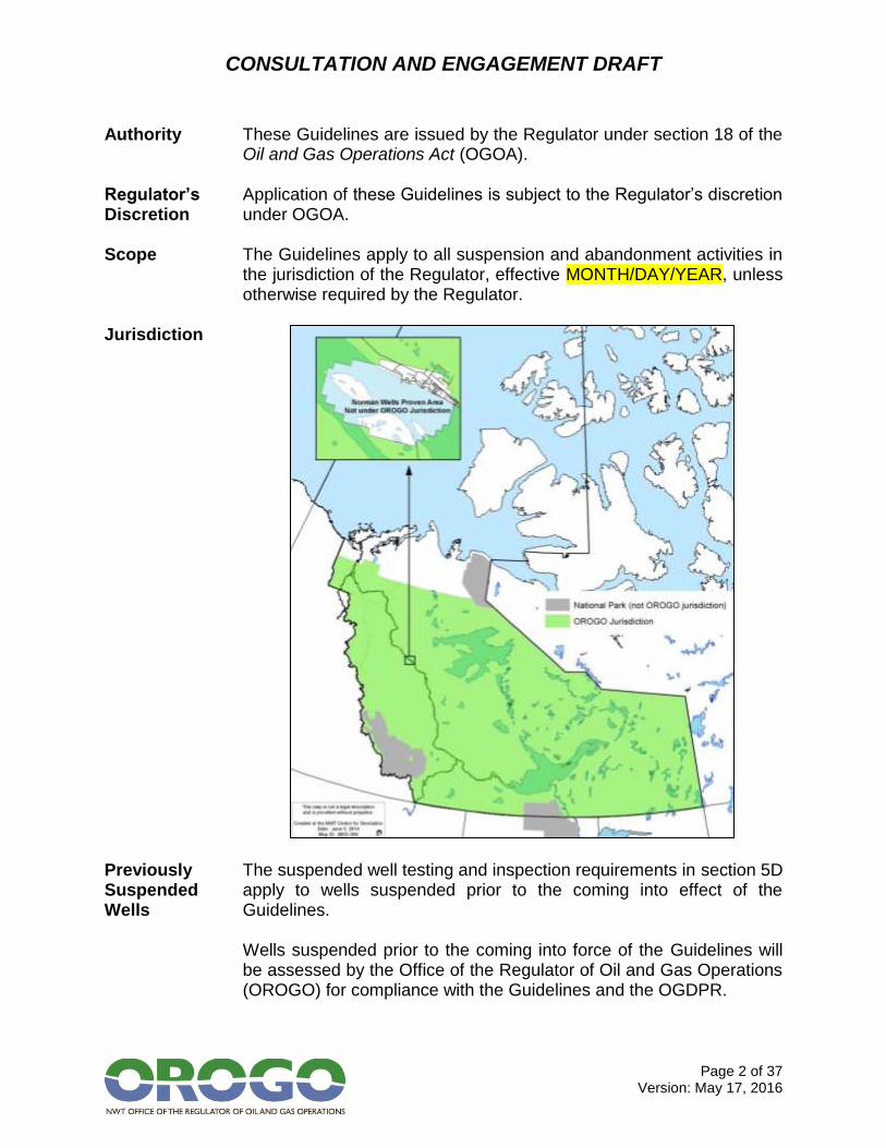
Jurisdiction
Previously Suspended Wells
The suspended well testing and inspection requirements in section 5D apply to wells suspended prior to the coming into effect of the Guidelines. Wells suspended prior to the coming into force of the Guidelines will be assessed by the Office of the Regulator of Oil and Gas Operations (OROGO) for compliance with the Guidelines and the OGDPR.
CONSULTATION AND ENGAGEMENT DRAFT
Page 3 of 37 Version: May 17, 2016
If a previously suspended well is found to be out of compliance with the Guidelines and/or OGDPR, OROGO will notify the operator of the well, which must abandon or re-suspend the well in accordance with these Guidelines within two years of notification. Operators of suspended wells must submit a plan to OROGO for the abandonment of those wells, in compliance with these Guidelines, at least two years before MONTH/DAY/YEAR [6 years after the Guidelines come into effect].
Previously Abandoned Wells and Zones
Wells and zones that were abandoned prior to the coming into force of the Guidelines are not required to be re-abandoned to the standards contained in these Guidelines. If a previously abandoned well or zone is re-entered, it must be abandoned as required in these Guidelines from the re-entry depth to surface. If a previously abandoned well or zone is found to be leaking, it must be re-abandoned as required in these Guidelines from the (repaired) leaking zone to surface.
Contents The Guidelines are organized as follows:
Section Contents Page
2 Well classification framework 4
3 Cement requirements 6
4 Gas migration, surface casing vent flow and annular pressure testing requirements
7
5 Well suspension and monitoring requirements 13
6 Well abandonment requirements 22
7 Process for applying to suspend or abandon a well
35
8 Regulator’s signature 37
CONSULTATION AND ENGAGEMENT DRAFT
Page 4 of 37 Version: May 17, 2016
2. WELL CLASSIFICATION FRAMEWORK
Contents This section describes the well classification framework used in these Guidelines.
Well Classification
These Guidelines classify wells based on their type and their risk level at the time of proposed suspension or abandonment.
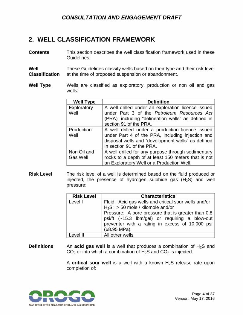
Well Type Wells are classified as exploratory, production or non oil and gas
wells:
Well Type Definition
Exploratory Well
A well drilled under an exploration licence issued under Part 3 of the Petroleum Resources Act (PRA), including “delineation wells” as defined in section 91 of the PRA.
Production Well
A well drilled under a production licence issued under Part 4 of the PRA, including injection and disposal wells and “development wells” as defined in section 91 of the PRA.
Non Oil and Gas Well
A well drilled for any purpose through sedimentary rocks to a depth of at least 150 meters that is not an Exploratory Well or a Production Well.
Risk Level The risk level of a well is determined based on the fluid produced or
injected, the presence of hydrogen sulphide gas (H2S) and well pressure:
Risk Level Characteristics
Level I Fluid: Acid gas wells and critical sour wells and/or H2S: > 50 mole / kilomole and/or Pressure: A pore pressure that is greater than 0.8 psi/ft (~15.3 lbm/gal) or requiring a blow-out preventer with a rating in excess of 10,000 psi (68.95 MPa).
Level II All other wells
Definitions An acid gas well is a well that produces a combination of H2S and
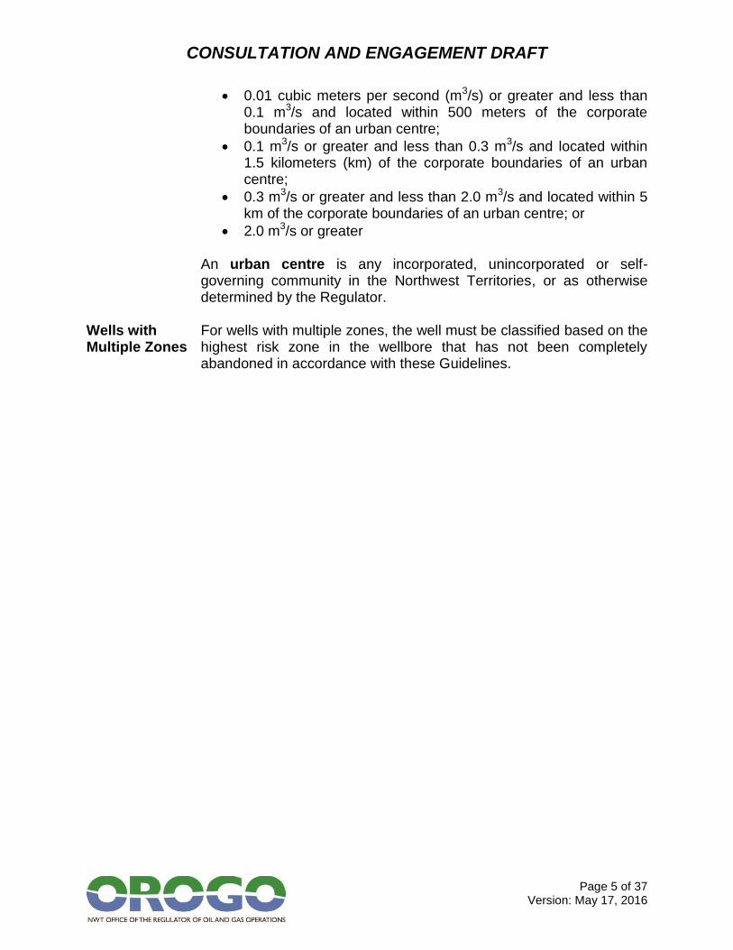
CO2 or into which a combination of H2S and CO2 is injected. A critical sour well is a well with a known H2S release rate upon completion of:
CONSULTATION AND ENGAGEMENT DRAFT
Page 5 of 37 Version: May 17, 2016
0.01 cubic meters per second (m3/s) or greater and less than 0.1 m3/s and located within 500 meters of the corporate boundaries of an urban centre;
0.1 m3/s or greater and less than 0.3 m3/s and located within 1.5 kilometers (km) of the corporate boundaries of an urban centre;
0.3 m3/s or greater and less than 2.0 m3/s and located within 5 km of the corporate boundaries of an urban centre; or
2.0 m3/s or greater An urban centre is any incorporated, unincorporated or self-governing community in the Northwest Territories, or as otherwise determined by the Regulator.
Wells with Multiple Zones
For wells with multiple zones, the well must be classified based on the highest risk zone in the wellbore that has not been completely abandoned in accordance with these Guidelines.
CONSULTATION AND ENGAGEMENT DRAFT
Page 6 of 37 Version: May 17, 2016
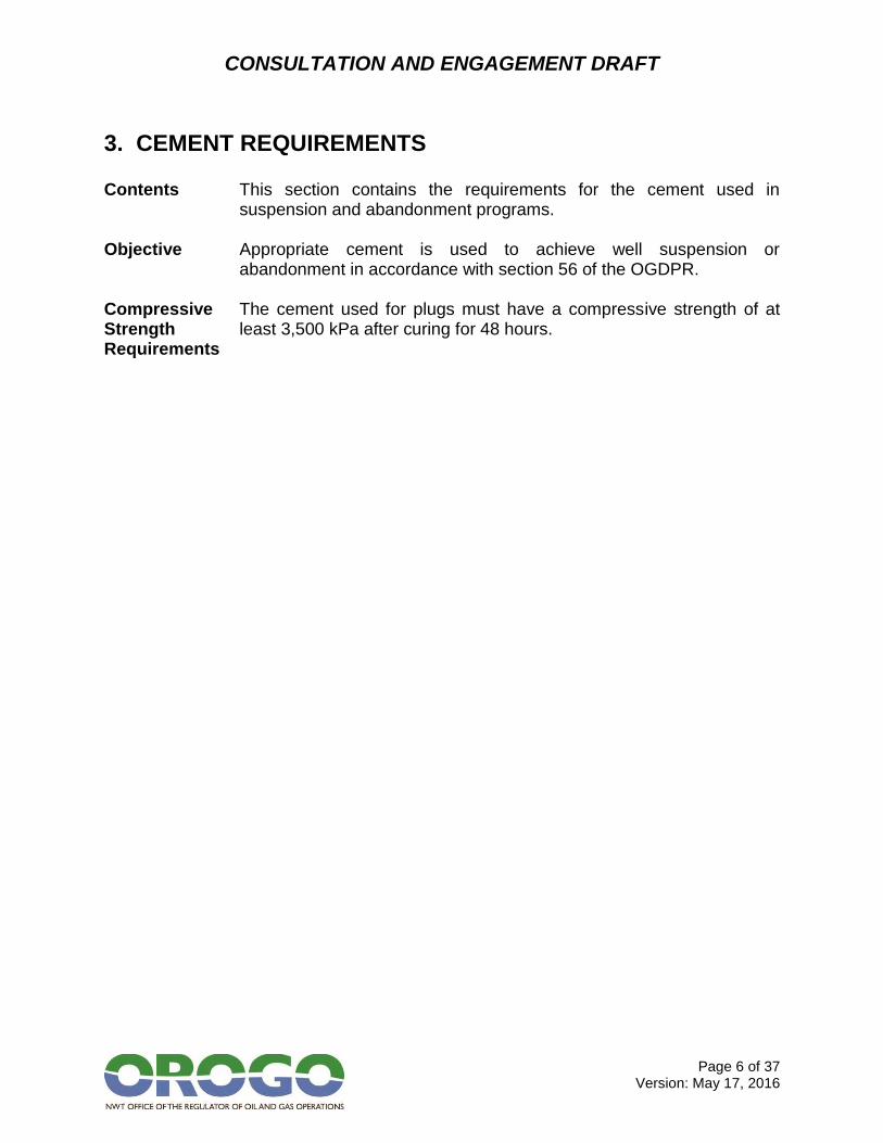
3. CEMENT REQUIREMENTS
Contents This section contains the requirements for the cement used in suspension and abandonment programs.
Objective Appropriate cement is used to achieve well suspension or
abandonment in accordance with section 56 of the OGDPR. Compressive Strength Requirements
The cement used for plugs must have a compressive strength of at least 3,500 kPa after curing for 48 hours.

CONSULTATION AND ENGAGEMENT DRAFT
Page 7 of 37 Version: May 17, 2016
4. GAS MIGRATION, SURFACE CASING VENT FLOW AND ANNULAR PRESSURE TESTING REQUIREMENTS
Contents This section contains the gas migration, surface casing vent flow and
annular pressure testing requirements for all wells:
Section 4A – Gas migration
Section 4B – Surface casing vent flow
Section 4C – Annular pressure
Section 4D – Casing failures Objective Gas migration, surface casing vent flows and annular pressures are
identified and addressed during suspension and abandonment processes.
Definitions Gas migration (GM) is a flow of gas that is detectable at surface
outside of the outermost casing string (often referred to as external migration or seepage). If there is a fire or public safety hazard or off-lease environmental damage, such as groundwater contamination, the GM is considered serious. Otherwise the GM is generally considered non-serious. Surface casing vent flow (SCVF) is the flow of gas and/or liquid or any combination out of the surface casing / casing annulus (often referred to as internal migration). An SCVF is considered serious if the vent flow: 1) Has a stabilized gas flow equal to or greater than 300 m3/day
and/or equal to a surface casing vent stabilized shut-in pressure greater than:
a. One-half the formation leak-off pressure at the surface casing shoe, or
b. 11 kPa/m times the surface casing setting depth; 2) Contains H2S; 3) Contains hydrocarbon liquid (oil); 4) Contains saline water (any water with total dissolved solids greater
than 4,000 mg/l); 5) Contains non-saline water where the surface shut-in pressure is as
referenced in 1(a) or (b); 6) Is due to a wellhead seal failure or casing failure; or
CONSULTATION AND ENGAGEMENT DRAFT
Page 8 of 37 Version: May 17, 2016
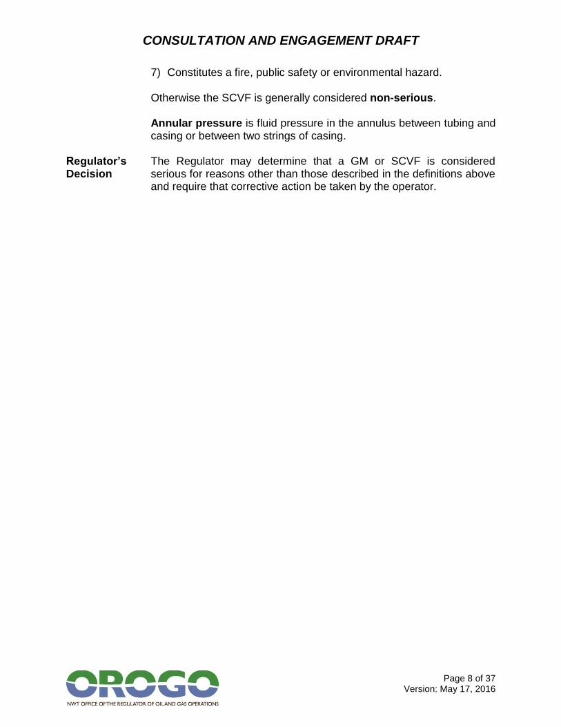
7) Constitutes a fire, public safety or environmental hazard. Otherwise the SCVF is generally considered non-serious. Annular pressure is fluid pressure in the annulus between tubing and casing or between two strings of casing.
Regulator’s Decision
The Regulator may determine that a GM or SCVF is considered serious for reasons other than those described in the definitions above and require that corrective action be taken by the operator.
CONSULTATION AND ENGAGEMENT DRAFT
Page 9 of 37 Version: May 17, 2016
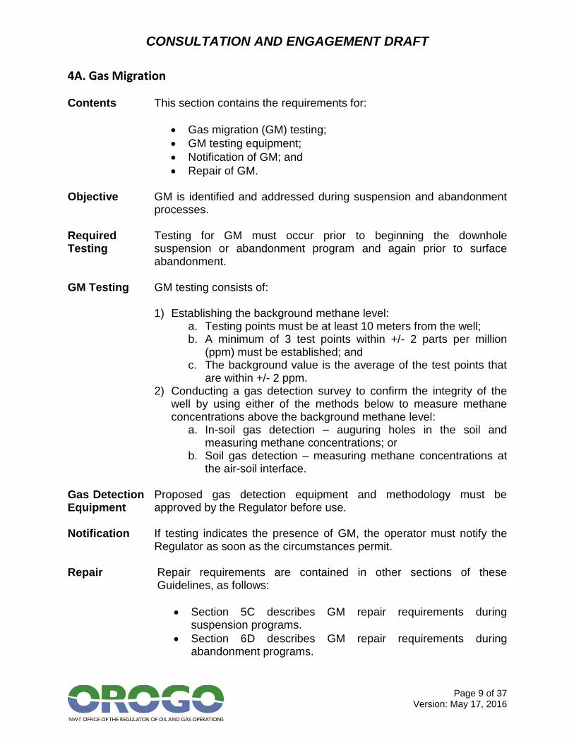
4A. Gas Migration Contents This section contains the requirements for:
Gas migration (GM) testing;
GM testing equipment;
Notification of GM; and
Repair of GM. Objective GM is identified and addressed during suspension and abandonment
processes. Required Testing
Testing for GM must occur prior to beginning the downhole suspension or abandonment program and again prior to surface abandonment.
GM Testing GM testing consists of:
1) Establishing the background methane level:
a. Testing points must be at least 10 meters from the well; b. A minimum of 3 test points within +/- 2 parts per million
(ppm) must be established; and c. The background value is the average of the test points that
are within +/- 2 ppm. 2) Conducting a gas detection survey to confirm the integrity of the
well by using either of the methods below to measure methane concentrations above the background methane level:
a. In-soil gas detection – auguring holes in the soil and measuring methane concentrations; or
b. Soil gas detection – measuring methane concentrations at the air-soil interface.
Gas Detection Equipment
Proposed gas detection equipment and methodology must be approved by the Regulator before use.
Notification If testing indicates the presence of GM, the operator must notify the
Regulator as soon as the circumstances permit. Repair Repair requirements are contained in other sections of these
Guidelines, as follows:
Section 5C describes GM repair requirements during suspension programs.
Section 6D describes GM repair requirements during abandonment programs.

CONSULTATION AND ENGAGEMENT DRAFT
Page 10 of 37 Version: May 17, 2016
4B. Surface Casing Vent Flow Contents This section contains the requirements for:
Surface casing vent flow (SCVF) testing;
SCVF rate determination;
Determination of stabilized shut-in surface casing pressure;
Notification of SCVF; and
Repair of SCVF. Objective SCVF is identified and addressed during suspension and
abandonment processes. Required Testing
Testing for SCVF must occur prior to beginning the downhole suspension or abandonment program and again prior to surface abandonment.
SCVF Testing SCVF testing consists of a bubble test, which must be conducted with
a hose 2.5 cm below the water surface for a minimum of 10 minutes. If any bubbles are presented during the 10 minutes test, the well has a vent flow.
SCVF Rate Determination
If bubbles were present during the bubble test, a surface casing vent flow rate test must be conducted. This test should be continued until a stabilized rated is obtained. The operator must use either a positive displacement gas meter or an orifice well tester to measure vented gas volumes.
Determination of Stabilized Shut-in Surface Casing Pressure
If bubbles were present during the bubble test, the surface casing vent must be shut in until a stabilized pressure is obtained. The pressure is considered stabilized if the change in pressure is less than 2 kPa/hr over a six hour period.
Notification If testing indicates the presence SCVF, the operator must notify the
Regulator as soon as the circumstances permit. Repair Repair requirements are contained in other sections of these
Guidelines, as follows:
Section 5C describes SCVF repair requirements during suspension programs.
Section 6D describes SCVF repair requirements during abandonment programs.
CONSULTATION AND ENGAGEMENT DRAFT
Page 11 of 37 Version: May 17, 2016
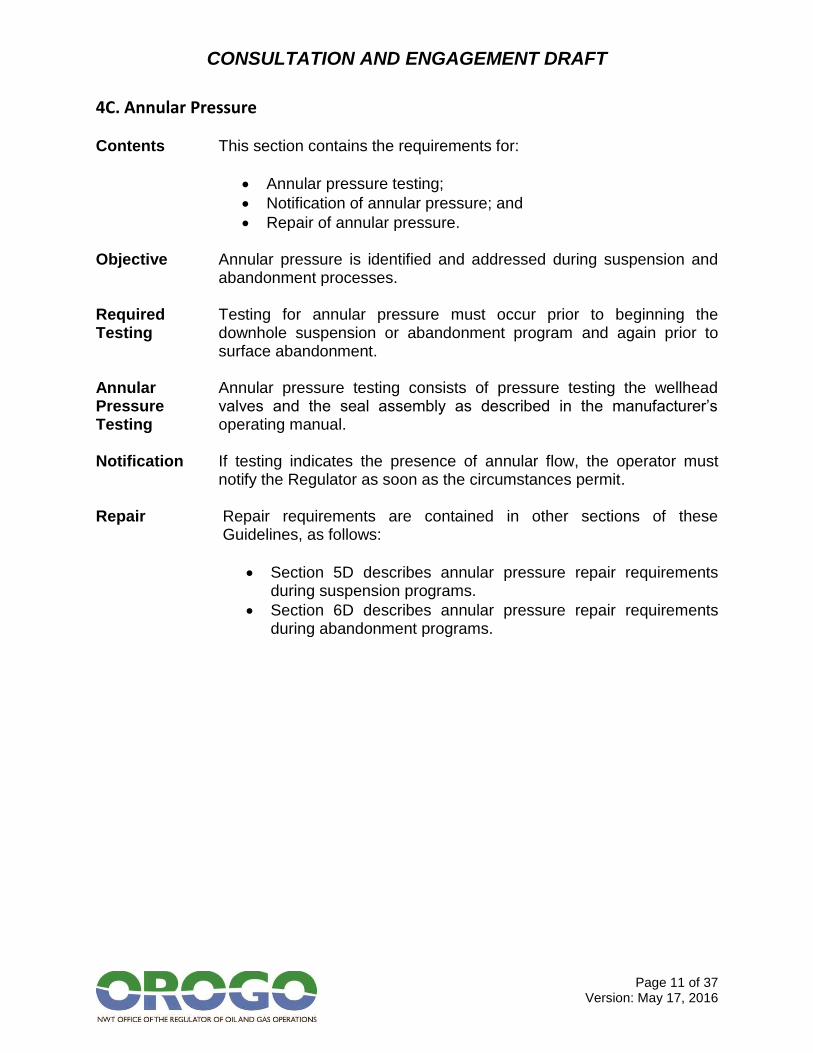
4C. Annular Pressure Contents This section contains the requirements for:
Annular pressure testing;
Notification of annular pressure; and
Repair of annular pressure. Objective Annular pressure is identified and addressed during suspension and
abandonment processes. Required Testing
Testing for annular pressure must occur prior to beginning the downhole suspension or abandonment program and again prior to surface abandonment.
Annular Pressure Testing
Annular pressure testing consists of pressure testing the wellhead valves and the seal assembly as described in the manufacturer’s operating manual.
Notification If testing indicates the presence of annular flow, the operator must
notify the Regulator as soon as the circumstances permit. Repair Repair requirements are contained in other sections of these
Guidelines, as follows:
Section 5D describes annular pressure repair requirements during suspension programs.
Section 6D describes annular pressure repair requirements during abandonment programs.
CONSULTATION AND ENGAGEMENT DRAFT
Page 12 of 37 Version: May 17, 2016
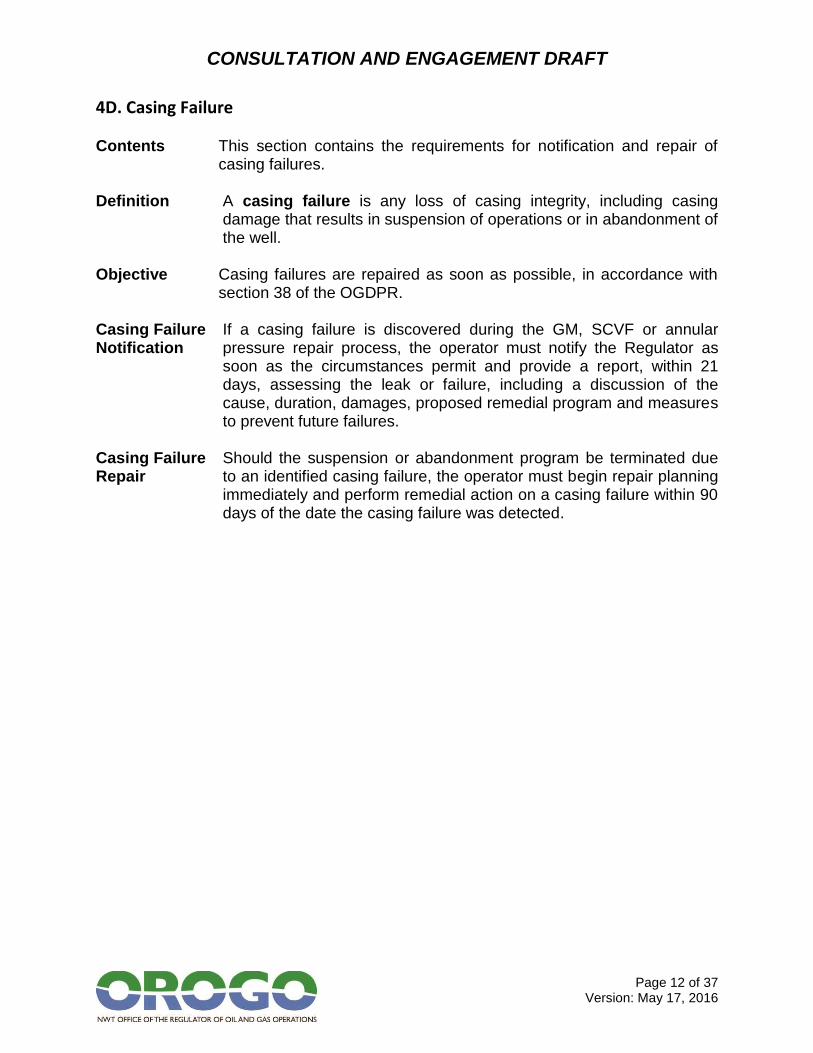
4D. Casing Failure Contents This section contains the requirements for notification and repair of
casing failures. Definition A casing failure is any loss of casing integrity, including casing
damage that results in suspension of operations or in abandonment of the well.
Objective Casing failures are repaired as soon as possible, in accordance with
section 38 of the OGDPR. Casing Failure Notification
If a casing failure is discovered during the GM, SCVF or annular pressure repair process, the operator must notify the Regulator as soon as the circumstances permit and provide a report, within 21 days, assessing the leak or failure, including a discussion of the cause, duration, damages, proposed remedial program and measures to prevent future failures.
Casing Failure Repair
Should the suspension or abandonment program be terminated due to an identified casing failure, the operator must begin repair planning immediately and perform remedial action on a casing failure within 90 days of the date the casing failure was detected.
CONSULTATION AND ENGAGEMENT DRAFT
Page 13 of 37 Version: May 17, 2016
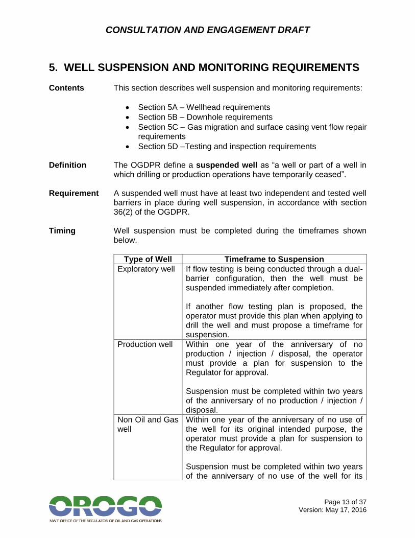
5. WELL SUSPENSION AND MONITORING REQUIREMENTS Contents This section describes well suspension and monitoring requirements:
Section 5A – Wellhead requirements
Section 5B – Downhole requirements
Section 5C – Gas migration and surface casing vent flow repair requirements
Section 5D –Testing and inspection requirements Definition The OGDPR define a suspended well as “a well or part of a well in
which drilling or production operations have temporarily ceased”. Requirement A suspended well must have at least two independent and tested well
barriers in place during well suspension, in accordance with section 36(2) of the OGDPR.
Timing Well suspension must be completed during the timeframes shown
below.
Type of Well Timeframe to Suspension
Exploratory well If flow testing is being conducted through a dual-barrier configuration, then the well must be suspended immediately after completion. If another flow testing plan is proposed, the operator must provide this plan when applying to drill the well and must propose a timeframe for suspension.
Production well Within one year of the anniversary of no production / injection / disposal, the operator must provide a plan for suspension to the Regulator for approval. Suspension must be completed within two years of the anniversary of no production / injection / disposal.
Non Oil and Gas well
Within one year of the anniversary of no use of the well for its original intended purpose, the operator must provide a plan for suspension to the Regulator for approval. Suspension must be completed within two years of the anniversary of no use of the well for its
CONSULTATION AND ENGAGEMENT DRAFT
Page 14 of 37 Version: May 17, 2016
original intended purpose.
Continued Responsibility
Operators must be able to demonstrate to the Regulator that wellbore integrity is being maintained at all times before, during and after well suspension activities.
CONSULTATION AND ENGAGEMENT DRAFT
Page 15 of 37 Version: May 17, 2016
5A – Wellhead Requirements for Suspended Wells Contents This section contains information on:
Standard wellhead requirements;
Critical sour wellhead requirements;
Wellhead maintenance requirements; and
Requirements for securing suspended wells. Objective The wellhead and Christmas tree on a suspended well should function
as a barrier under the maximum load condition. Standard Wellheads
Wellheads for suspended wells must be consistent with Minimum Wellhead Requirements – An Industry Recommended Practice (IRP) for the Canadian Oil and Gas Industry, issued by the Enform Drilling and Completion Committee, unless the well is classified critical sour.
Critical Sour Wellheads
Wellheads for suspended critical sour wells must be consistent with Completing and Servicing Critical Sour Wells – Industry Recommended Practice (IRP), issued by the Enform Drilling and Completion Committee.
Definitions A critical sour well is a well with a known H2S release rate upon
completion of:
0.01 cubic meters per second (m3/s) or greater and less than 0.1 m3/s and located within 500 meters of the corporate boundaries of an urban centre;
0.1 m3/s or greater and less than 0.3 m3/s and located within 1.5 kilometers (km) of the corporate boundaries of an urban centre;
0.3 m3/s or greater and less than 2.0 m3/s and located within 5 km of the corporate boundaries of an urban centre; or
2.0 m3/s or greater An urban centre is any incorporated, unincorporated or self-governing community in the Northwest Territories, or as otherwise determined by the Regulator.
Wellhead Maintenance
Wellhead maintenance requirements for suspended wells are:
There shall be no wellhead leaks;
Regular wellheads require servicing and pressure testing of sealing elements at time of suspension and at each subsequent inspection (see Section 5D);
CONSULTATION AND ENGAGEMENT DRAFT
Page 16 of 37 Version: May 17, 2016
All outlets except surface casing vents are to be bull plugged or blind flanged with needle valves;
Valves must be functional (open/close); and,
Grease and service as required to maintain functionality. Securing Suspended Wells
Requirements for securing suspended wells are:
All wellheads are to be conspicuously marked or fenced such that they are visible in all seasons with well identification sign in plain view;
Land uses in the area must be restricted to safe distances from the wellhead;
Pumpjacks must be left in a secure condition;
Valve handles must be chained and locked or, as an alternative, valve handles may be removed; and
Physical barriers that are clearly visible must be constructed around wellheads to prevent accidental vehicular damage.

CONSULTATION AND ENGAGEMENT DRAFT
Page 17 of 37 Version: May 17, 2016
5B – Downhole Well Suspension Requirements
Contents This section contains information on downhole well suspension requirements:
Downhole suspension options for different well types and risk levels;
Requirements for bridge plugs;
Requirements for packer and tubing plugs; and
Wellbore fluid requirements. Objective A suspended well must have at least two independent and tested
well barriers in place during well suspension and must be suspended in accordance with section 56 of the OGDPR. Wells must be suspended in a manner that enables the safe resumption of operations.
Wellhead is a Barrier
An approved wellhead, properly maintained and functioning as outlined in section 5A, is an independent barrier to flow for the purposes of suspension.
Downhole Suspension
Downhole suspension requirements vary by type of well, as shown below.
Well Type / Risk Level
Downhole Suspension Requirements
Level I exploratory and production wells
Option 1 – Packer and a tubing plug, pressure tested as required in section 5D Option 2 – Bridge plug capped with 8 meters of lineal cement, pressure tested as required in section 5D
Level II exploratory and production wells
Option 1 – Packer and a tubing plug, pressure tested as required in section 5D Option 2 – Bridge plug, pressure tested as required in section 5D
Non oil and gas wells
Option 1 – Suspend using one of the options for Level II exploratory and production wells Option 2 – Apply to the Regulator for a waiver to the Level II well suspension requirements under section 54 of OGOA and propose an alternative approach.
CONSULTATION AND ENGAGEMENT DRAFT
Page 18 of 37 Version: May 17, 2016
Bridge Plugs Retrievable bridge plugs are acceptable for use during suspension,
but not during abandonment. Operators should consider the setting depth required for abandonment when placing bridge plugs for suspension.
Packer and Tubing Plugs
Packer and tubing plugs are acceptable for use during suspension, but not during abandonment.
Wellbore Fluid The wellbore must be filled with inhibited fluid. Non-freezing liquid
must be used within the permafrost zone.
CONSULTATION AND ENGAGEMENT DRAFT
Page 19 of 37 Version: May 17, 2016
5C – Gas Migration and Surface Casing Vent Flow Testing and Repair Requirements during Well Suspension
Contents This section contains direction on addressing GM and SCVF identified
during well suspension programs. Objective GM and SCVF in suspended wells are risk managed in a way that
reflects the severity of the issue. Required Testing
Testing for GM and/or SCVF must occur prior to beginning the downhole suspension (see section 4).
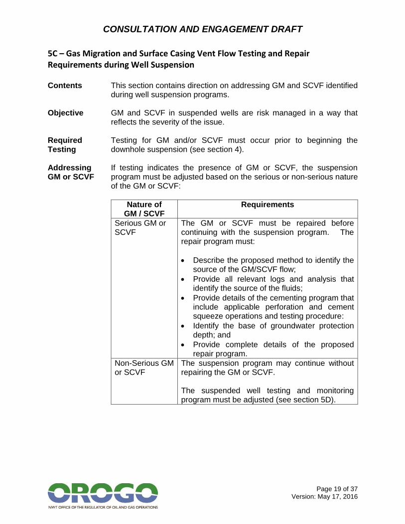
Addressing GM or SCVF
If testing indicates the presence of GM or SCVF, the suspension program must be adjusted based on the serious or non-serious nature of the GM or SCVF:
Nature of GM / SCVF
Requirements
Serious GM or SCVF
The GM or SCVF must be repaired before continuing with the suspension program. The repair program must:
Describe the proposed method to identify the source of the GM/SCVF flow;
Provide all relevant logs and analysis that identify the source of the fluids;
Provide details of the cementing program that include applicable perforation and cement squeeze operations and testing procedure:
Identify the base of groundwater protection depth; and
Provide complete details of the proposed repair program.
Non-Serious GM or SCVF
The suspension program may continue without repairing the GM or SCVF. The suspended well testing and monitoring program must be adjusted (see section 5D).
CONSULTATION AND ENGAGEMENT DRAFT
Page 20 of 37 Version: May 17, 2016
5D –Testing and Inspection Requirements for Suspended Wells
Contents This section contains information on the pressure testing and inspection requirements for suspended wells:
Testing requirements for Level I and Level II exploratory and production wells;
Inspection frequencies for Level I and Level II exploratory and production wells;
Requirements for wells with non-serious GM or SCVF;
Requirements for non oil and gas wells; and
Notification of failures, including annular pressure. Objective All wells are monitored and inspected in accordance with section 57
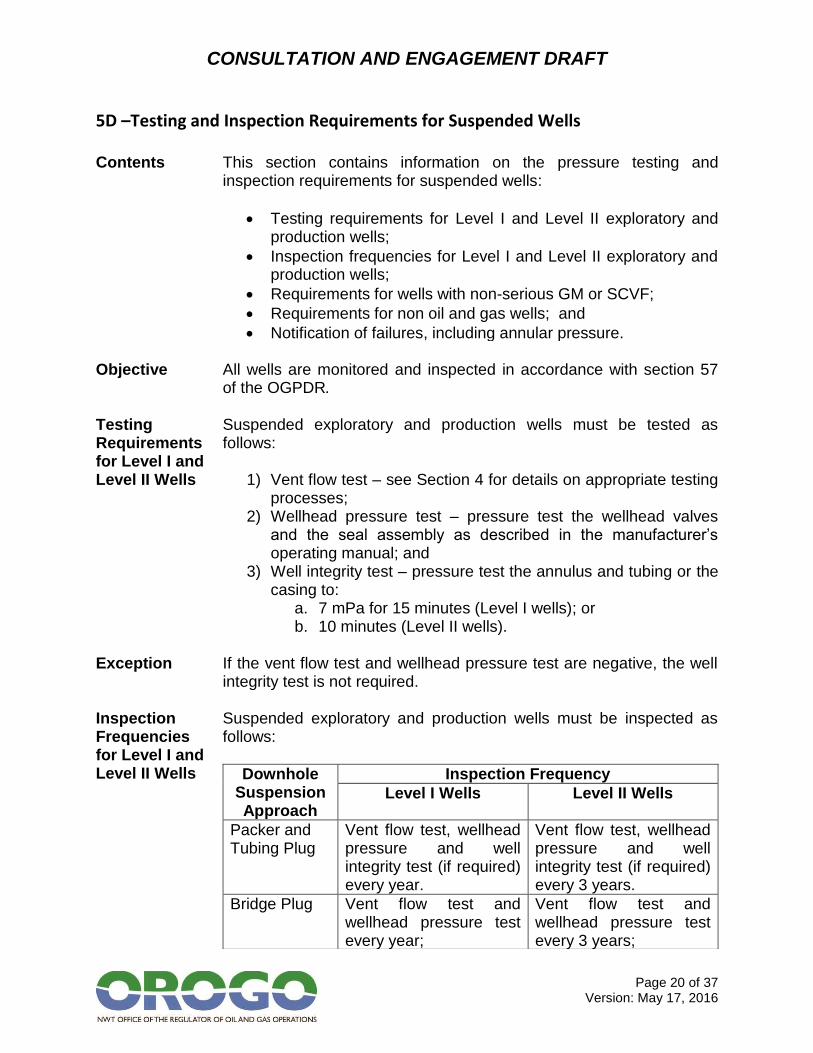
of the OGPDR. Testing Requirements for Level I and Level II Wells
Suspended exploratory and production wells must be tested as follows:
1) Vent flow test – see Section 4 for details on appropriate testing processes;
2) Wellhead pressure test – pressure test the wellhead valves and the seal assembly as described in the manufacturer’s operating manual; and
3) Well integrity test – pressure test the annulus and tubing or the casing to:
a. 7 mPa for 15 minutes (Level I wells); or b. 10 minutes (Level II wells).
Exception If the vent flow test and wellhead pressure test are negative, the well
integrity test is not required. Inspection Frequencies for Level I and Level II Wells
Suspended exploratory and production wells must be inspected as follows:
Downhole Suspension Approach
Inspection Frequency
Level I Wells Level II Wells
Packer and Tubing Plug
Vent flow test, wellhead pressure and well integrity test (if required) every year.
Vent flow test, wellhead pressure and well integrity test (if required) every 3 years.
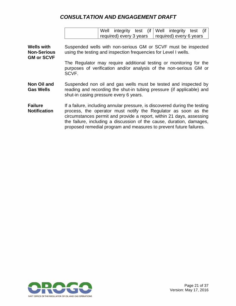
Bridge Plug Vent flow test and wellhead pressure test every year;
Vent flow test and wellhead pressure test every 3 years;
CONSULTATION AND ENGAGEMENT DRAFT
Page 21 of 37 Version: May 17, 2016
Well integrity test (if required) every 3 years
Well integrity test (if required) every 6 years
Wells with Non-Serious GM or SCVF
Suspended wells with non-serious GM or SCVF must be inspected using the testing and inspection frequencies for Level I wells. The Regulator may require additional testing or monitoring for the purposes of verification and/or analysis of the non-serious GM or SCVF.
Non Oil and Gas Wells
Suspended non oil and gas wells must be tested and inspected by reading and recording the shut-in tubing pressure (if applicable) and shut-in casing pressure every 6 years.
Failure Notification
If a failure, including annular pressure, is discovered during the testing process, the operator must notify the Regulator as soon as the circumstances permit and provide a report, within 21 days, assessing the failure, including a discussion of the cause, duration, damages, proposed remedial program and measures to prevent future failures.
CONSULTATION AND ENGAGEMENT DRAFT
Page 22 of 37 Version: May 17, 2016
6. WELL ABANDONMENT REQUIREMENTS
Contents This section contains the abandonment requirements for all wells:
Section 6A – Downhole abandonment requirements o Section 6Ai – Requirements for non oil and gas wells
Section 6B – Groundwater protection
Section 6C – Confirming location of cement plugs
Section 6D – Gas migration and surface casing vent flow repair
Section 6E – Surface abandonment
Section 6F – Responsibility for abandoned wells Definition The OGDPR define an abandoned well as a well or part of a well
that has been permanently plugged. Interpretation Permanently plugging a well requires both downhole abandonment
and surface abandonment. Timing All wells must be abandoned in accordance with these Guidelines
within 6 years of suspension.

CONSULTATION AND ENGAGEMENT DRAFT
Page 23 of 37 Version: May 17, 2016
6A – Downhole Abandonment Requirements
Contents This section contains information on the downhole abandonment requirements for:
Cement evaluation;
Wellbore fluid
Determining the appropriate abandonment method; and
Abandonment methods for: o Cased-hole wells with no perforations; o Wells with cemented liners; o Wells with uncemented liners across more than one
zone; o Wells with casing patching, casing failures and
previously cement squeezed intervals; o Cased hole wells with perforations; and o Wells with existing Level I zonal abandonments.
Application This section of the Guidelines applies to Level I and Level II
exploratory and production wells. Objective Each completed pool or zone must be abandoned separately and all
non-saline groundwater zones must be covered with cement or isolated from each other.
Cement Evaluation
The operator must evaluate the existing cement behind the casing string(s) of a well before beginning abandonment operations. The evaluation must include:
Determining the cement top;
Evaluating cement bond in the casing annulus; and
Assessing any repairs or remedial cementing required to isolate all oil or gas bearing zones, discreet pressure zones and potable water zones, including consideration of any lost circulation zones.
Wellbore Fluid The wellbore must be filled with inhibited fluid. Non-freezing liquid
must be used within the permafrost zone. Determining Abandonment Method
The approved abandonment method varies depending on the structure of the well and its risk level. The operator should work from the bottom of the casing upwards, using an approved method for each section.
CONSULTATION AND ENGAGEMENT DRAFT
Page 24 of 37 Version: May 17, 2016
Cased-hole Wells with No Perforations
For Level I and Level II wells, no additional cement plugs are required to be run if the existing casing string is pressure tested at a stabilized pressure of 7,000 kPa for 10 minutes. Must be filled with nonsaline water.
Wells with Cemented Liners
For Level I and Level II wells, the completed interval must be abandoned in accordance with these Guidelines. Following abandonment of the completed interval, the operator must use one of the following options for abandoning a liner top in a well with a cemented liner before surface abandonment: 1) Setting a permanent bridge plug within 15 meters above the liner
top. 2) Setting a cement plug across the liner top which extends from a
minimum of 15 vertical meters below the cemented liner top to a minimum of 15 vertical meters above the cemented liner top.
Wells with Uncemented Liners Across More Than One Zone
For Level I and Level II wells, the zones behind the liner must be evaluated for porosity and a cement squeeze(s) must be conducted to ensure isolation between the zones. Once the liner has been cemented, follow the requirements for wells with cemented liners.
Wells with Casing Patching, Casing Failures and Previously Cement Squeezed Intervals
The operator must use one of the following options, based on the risk level of the zone where the failure occurred. If previously cement squeezed intervals are drilled out over more than one zone, each zone must be isolated by one of these methods. For casing failures that cover more than one zone, a cement squeeze must be conducted as per option #2: Level I options: 1) Permanent Bridge Plug with Circulated Cement - Setting a
permanent bridge plug within 15 meters above the interval and circulating 30 vertical meters of cement. The plug must be pressure tested at a stabilized pressure of 7,000 kPa for 15 minutes.
2) Cement Plug and Squeeze - Setting a cement plug and squeezing cement from a minimum of 30 vertical meters below the interval to a minimum of 30 vertical meters above the top of the interval. The plug must be circulated in place and have a minimum volume of 1 m3. The final squeeze pressure must be at least 7,000 kPa. After the location of the plug is confirmed (see
CONSULTATION AND ENGAGEMENT DRAFT
Page 25 of 37 Version: May 17, 2016
section 6C), the plug must be pressure tested at a stabilized pressure of 7,000 kPa for 15 minutes.
Level II options: 1) Permanent Bridge Plug with Circulated Cement – setting a
permanent bridge plug within 15 meters above the interval and circulating 15 vertical meters of cement. The bridge plug must be pressure tested at a stabilized pressure of 7,000 kPa for 10 minutes.
2) Cement Plug and Squeeze - Setting a cement plug and squeezing cement from a minimum of 15 vertical meters below the interval to a minimum of 15 vertical meters above the top of the interval. The plug must be circulated in place and have a minimum volume of 1 m3. The final squeeze pressure must be at least 7,000 kPa. After the location of the plug is confirmed (see section 6C), the plug must be pressure tested at a stabilized pressure of 7,000 kPa for 10 minutes
Cased Hole Wells with Perforations
The operator must use one of the following options, based on the risk level of the perforated zone to be abandoned: Level I options: 1) Cement squeeze and cement retainer with a minimum of 60
meters of circulated cement. 2) Cement squeeze and cement/bridge plug with a minimum of 60
meters of circulated cement. 3) Permanent bridge plug with a minimum of 60 meters of circulated
cement. Level II options: 1) Cement squeeze and cement retainer with a minimum of 30
meters of circulated cement. 2) Cement squeeze and cement/bridge plug with a minimum of 30
meters of circulated cement. 3) Permanent bridge plug with a minimum of 30 meters of circulated
cement. Wells with Existing Level I Zonal Abandonments
If a well has an existing Level I zonal abandonment, an additional cement plug must be circulated on top of the uppermost previously abandoned zone. This cement plug must be a minimum length of 30 vertical meters and have a minimum volume of 1 m3. The base of this plug must be located below the non-saline ground water. If the uppermost previously abandoned zone’s plug is above the non-saline groundwater:
CONSULTATION AND ENGAGEMENT DRAFT
Page 26 of 37 Version: May 17, 2016
The plug must be drilled out; and
An additional cement plug must be circulated on top of the uppermost previously abandoned zone. This cement plug must be a minimum length of 3 vertical meters. All perforations above this point must be abandoned as required in these Guidelines.
CONSULTATION AND ENGAGEMENT DRAFT
Page 27 of 37 Version: May 17, 2016
6Ai – Requirements for Abandonment of Non Oil and Gas Wells
Contents This section contains the abandonment requirements for non oil and gas wells.
Limited Application
This section of the Guidelines applies only to non oil and gas wells.
Objective Non oil and gas wells are abandoned in accordance section 56 of the
OGDPR. Downhole Abandonment
Non oil and gas wells may:
Be abandoned as required for Level II wells in section 6A of these Guidelines; or
The operator may apply to the Regulator for approval to abandon the well by cementing from total depth (TD) to at least the bottom 15 meters of the casing string (this approach requires a waiver under section 54 of OGOA).
Pre-Surface Abandonment Testing
A fluid level test must be completed prior to surface abandonment of a non oil and gas well and at least five days after downhole abandonment operations have been completed.
Fluid Level Test
A fluid level test requires a visual inspection of the well to ensure that the fluid level inside the casing is static and there are no gas bubbles present.
Leaking Plug If the fluid level test reveals a leaking plug:
It must be reported to the Regulator as soon as circumstances permit;
The operator must develop and submit a repair program to the Regulator for approval within 21 days; and
The leak must be repaired prior to continuing with the abandonment program.
Surface Abandonment
Non oil and gas wells must be surface abandoned as required in section 6E of these Guidelines.
CONSULTATION AND ENGAGEMENT DRAFT
Page 28 of 37 Version: May 17, 2016
6B – Groundwater Protection Requirements
Contents This section contains information on groundwater protection requirements during well abandonment operations.
Objective All wells must be abandoned in a manner that isolates potable water
zones, in accordance with section 56 of the OGDPR. Interpretation Potable water is interpreted to mean non-saline groundwater. Definition Non-saline groundwater is water that has total dissolved solids less
than or equal to 4,000 milligrams per litre. Lack of Groundwater Data
If no data is available on the salinity of the groundwater, protection must extend to 600 meters below the surface.
Existing Isolation
If non-saline groundwater is already isolated through the construction of the well, the operator must provide proof of this isolation to the Regulator when applying to abandon the well.
Remedial Isolation
If non-saline groundwater is not already isolated, the operator must conduct remedial cementing operations to isolate the non-saline groundwater as follows:
1) Identify the base of the non-saline groundwater requiring isolation;
2) Perforate, mill or slat the casing at the base of non-saline groundwater;
3) Attempt to establish circulation to surface with non-saline water;
a. If circulation to surface is successful, isolate the non-saline ground water using a cement retainer, Bradenhead cement plug and squeeze or Bullhead cement and squeeze.
4) If circulation to surface is unsuccessful, attempt to establish a feed rate.
a. If a feed rate is established, isolate the non-saline groundwater using a cement retainer and squeeze or Bradenhead cement plug and squeeze.
b. If a feed rate is not established, isolate the non-saline groundwater using a Bradenhead cement plug and squeeze.
CONSULTATION AND ENGAGEMENT DRAFT
Page 29 of 37 Version: May 17, 2016
6C – Requirements for Locating Cement Plugs
Contents This section contains information on the acceptable methods for confirming the location of cement plugs.
Objective The location of cement plugs must be accurately determined and
reported to the Regulator. Acceptable Methods
The following methods for confirming the location of cement plugs are acceptable:
Strap tally – measuring and counting joints of drill pipe;
Direct density plug logging – using a radioactive source and a detector run on wireline;
Hydrostatic pressure plug logging – using a pressure transducer run on wireline; and
Radioactive tracer logging – using a radioactive tracer introduced into the lead slurry.
Not Acceptable
The use of slick line or wireline is not an acceptable method for locating the plug top.
Reporting Requirements
The locations of cement plugs, the method used to identify them and the plug logs (for all methods except strap tally) must be reported to the Regulator in the Well Operations Report.
CONSULTATION AND ENGAGEMENT DRAFT
Page 30 of 37 Version: May 17, 2016
6D – Gas Migration, Surface Casing Vent Flow and Annular Pressure Testing and Repair Requirements during Well Abandonment
Contents This section contains direction on addressing GM, SCVF and annular
pressure identified during well abandonment programs. Objective Abandoned wells do not have any GM, SCVF or annular pressure, in
accordance with section 56 of the OGDPR. Required Testing
Testing for GM and/or SCVF and for annular pressure must occur prior to beginning downhole abandonment (see section 4) and prior to surface abandonment.
GM, SCVF or Annular Pressure Repair
All GM or SCVF (serious and non-serious) and annular pressure must be repaired prior to abandoning the well. The repair program must:
Describe the proposed method to identify the source of the GM/SCVF flow;
Provide all related logs and log analysis;
Provide casing and cementing details:
Identify the base of groundwater protection depth; and
Provide complete details of the proposed repair program.
CONSULTATION AND ENGAGEMENT DRAFT
Page 31 of 37 Version: May 17, 2016
6E – Surface Abandonment Requirements
Contents This section contains information on surface abandonment requirements:
Timing of surface abandonment;
Cutting and capping requirements; and
Well signage requirements. Objective All well heads are removed from abandoned wells and the wells are
easily locatable. Definition Surface abandonment is the cutting off of casing string(s) and the
capping of a well. Timing The timing requirements for surface abandonment are:
The operator must not begin surface abandonment until GM/SCVF and annular pressure testing (see section 4) has been performed and the test results indicate the absence of any wellbore problem;
Surface abandonment must be completed within 12 months after downhole abandonment operations are completed and any well integrity issues are repaired;
If the well is being abandoned due to an order of the Regulator, the operator must begin surface abandonment as directed; and
Debris associated with the entire well operation must be removed within 12 months of the cutting and capping operation.
Definition Debris is:
Any installation of structure that was put in place as a result of an authorized activity and that has been abandoned without the Regulator’s authorization; or
Any material that has broken away or been jettisoned or displaced in the course of an authorized activity.
Cutting and Capping
The requirements for cutting and capping are:
The casing string(s) must be cut off a minimum of 1 meter below the natural ground level;
Surface, intermediate and production casing strings must be capped at surface with a steel plate that is fastened and
CONSULTATION AND ENGAGEMENT DRAFT
Page 32 of 37 Version: May 17, 2016
installed in a manner as to prevent any potential for pressure to build up within the casings while restricting access to the casing strings at surface; and
A vented capping system, with consideration given to a capping system that facilitates well control in the event of a failure post-abandonment.
Reporting Field verified coordinates for the well centre must be provided as part
of the Well Operations Report as follows:
The geodetic datum must be specified; and
Coordinates must be provided: o In decimal degrees to 4 decimal places or more, or o In degrees, minutes and seconds to 2 decimal places, if
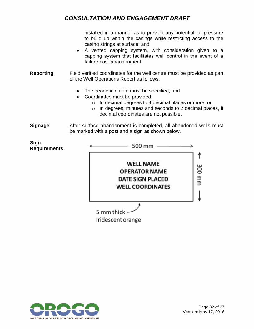
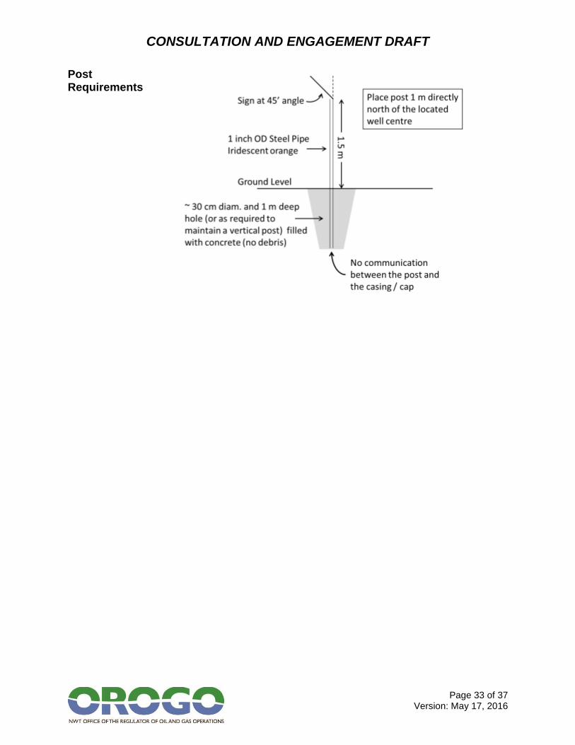
decimal coordinates are not possible. Signage After surface abandonment is completed, all abandoned wells must
be marked with a post and a sign as shown below. Sign Requirements
CONSULTATION AND ENGAGEMENT DRAFT
Page 33 of 37 Version: May 17, 2016
Post Requirements
CONSULTATION AND ENGAGEMENT DRAFT
Page 34 of 37 Version: May 17, 2016
6F – Responsibility for Abandoned Wells
Contents This section contains information on the impact of a change of operator for an abandoned well.
Objective Abandoned wells continue to be the responsibility of an identifiable
operator. Change of Ownership
If the original operator transfers an abandoned well to a successor company, the successor assumes all responsibility for the control or further abandonment of the well and for the costs of doing that work. If a successor company transfers an abandoned well to a further successor company, the responsibility for the control or further abandonment of the well and for the costs of doing that work are also transferred.
Reporting to the Regulator
All changes in well operators must be reported to the Regulator within one month of the change.
CONSULTATION AND ENGAGEMENT DRAFT
Page 35 of 37 Version: May 17, 2016
7. APPLYING TO SUSPEND OR ABANDON A WELL
Well Operation
Suspending or abandoning a well is a “well operation” as defined in the OGDPR. Proposals for well operations must be approved by the Regulator before they can proceed.
Application Requirements
Application requirements depend on whether an Operations Authorization that includes suspension or abandonment within its scope is already in place for the well, as shown below.
Application Requirements
No Existing Operations Authorization
Submission of Application for an Operations Authorization form and supporting documentation as required under OGOA and the OGDPR; and
Submission of an Application to Alter the Condition of a Well form and supporting documentation as required under the OGDPR.
Existing Operations Authorization
Submission of an Application to Alter the Condition of a Well form and supporting documentation as required under the OGDPR.
Application Forms
Application forms are available on the Regulator’s website: www.orogo.gov.nt.ca/documents.
Document Submission Guidelines
Information on the number and type of copies required for an application can be found in the Document Submission Guidelines on the Regulator’s website: www.orogo.gov.nt.ca/documents.
Operations Authorization Process
OROGO reviews an application for an Operations Authorization by:
Reviewing the application for completeness against the requirements of OGOA and the OGDPR;
Ensuring an approved Benefits Plan is in place that covers the scope of the proposed activity;
Assessing whether sufficient consultation has taken place with potential affected Aboriginal governments and organizations;
Confirming that the proposed work or activity conforms with the appropriate Land Use Plan (where available);
Undertaking a technical review of the application;
Issuing Information Requests (if additional information is required to complete the review);
Ensuring the Regulator’s preliminary screening obligations under the Mackenzie Valley Resource Management Act are met; and
CONSULTATION AND ENGAGEMENT DRAFT
Page 36 of 37 Version: May 17, 2016
Assessing the proof of financial responsibility required. Altering the Condition of a Well Process
OROGO reviews an application to Alter the Condition of a Well by:
Reviewing the application for completeness against the requirements of the OGDPR;
Undertaking a technical review of the application; and
Issuing information Requests (if additional information is required to complete the review).
Timeframes for Decision
OROGO’s standards for processing applications are:
For Operations Authorizations related to exploratory work, a maximum of 90 calendar days from receipt of a complete application, not including any additional time required to complete an environmental assessment or environmental impact assessment.
For Well Approvals (including well suspensions and abandonments) under an existing Operations Authorization, a maximum of 30 calendar days from receipt of a complete application.
Definition A complete application contains all of the information required under
OGOA and the OGDPR and requires confirmation of an approved benefits plan.
CONSULTATION AND ENGAGEMENT DRAFT
Page 37 of 37 Version: May 17, 2016
8. REGULATOR’S SIGNATURE BLOCK
These Suspension and Abandonment Guidelines and Interpretation Notes are issued under section 18 of the Oil and Gas Operations Act effective MONTH/DAY/YEAR. _______________________________ Louis Sebert Regulator