Embed Size (px)
Citation preview
DIG
ITAL
MET
ERS
11
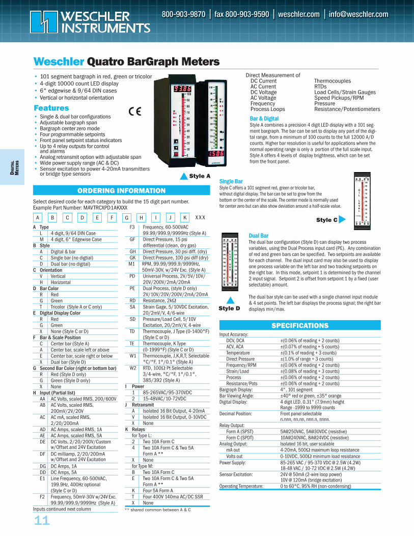
Weschler Quatro BarGraph Meters• 101 segment bargraph in red, green or tricolor• 4-digit 10000 count LED display• 6" edgewise & 9/64 DIN cases• Vertical or horizontal orientation
Style A
Direct Measurement ofDC CurrentAC CurrentDC VoltageAC VoltageFrequencyProcess Loops
ThermocouplesRTDsLoad Cells/Strain GaugesSpeed Pickups/RPMPressureResistance/Potentiometers
SPECIFICATIONS
DDuuaall BBaarrThe dual bar configuration (Style D) can display two process variables, using the Dual Process input card (PE). Any combinationof red and green bars can be specified. Two setpoints are availablefor each channel. The dual input card may also be used to displayone process variable on the left bar and two tracking setpoints onthe right bar. In this mode, setpoint 1 is determined by the channel2 input signal. Setpoint 2 is offset from setpoint 1 by a fixed (userselectable) amount.
The dual bar style can be used with a single channel input module& 4 set points. The left bar displays the process signal; the right bardisplays min/max.
SSiinnggllee BBaarr Style C offers a 101 segment red, green or tricolor bar, without digital display. The bar can be set to grow from the bottom or the center of the scale. The center mode is normally usedfor center zero but can also show deviation around a half-scale value.
BBaarr && DDiiggiittaallStyle A combines a precision 4 digit LED display with a 101 seg-ment bargraph. The bar can be set to display any part of the digi-tal range, from a minimum of 100 counts to the full 12000 A/Dcounts. Higher bar resolution is useful for applications where thenormal operating range is only a portion of the full scale input.Style A offers 4 levels of display brightness, which can be setfrom the front panel.
Style C
Style D
ORDERING INFORMATIONSelect desired code for each category to buiId the 15 digit part number.Example Part Number: MAVTRCXPD1AKXXX
A B C D E F G H X X X
A TypeL 4 digit, 9/64 DIN CaseM 4 digit, 6" Edgewise Case
B StyleA Digital & barC Single bar (no digtial)D Dual bar (no digital)
C OrientationV VerticalH Horizontal
D Bar ColorR RedG GreenT Tricolor (Style A or C only)
E Digital Display ColorR RedG GreenX None (Style C or D)
F Bar & Scale PositionC Center bar (Style A)A Center bar, scale left or aboveE Cemter bar, scale right or belowX Dual bar (Style D)
G Second Bar Color (right or bottom bar) R Red (Style D only)G Green (Style D only)X None
H Input (Partial list)AA AC Volts, scaled RMS, 200/600V AB AC Volts, scaled RMS,
200mV/2V/20V AC AC mA, scaled RMS,
2/20/200mA AD AC Amps, scaled RMS, 1A AE AC Amps, scaled RMS, 5A DE DC Volts, 2/20/200V/Custom
w/Offset and 24V ExcitationDF DC milliamp, 2/20/200mA
w/Offset and 24V ExcitationDG DC Amps, 1ADD DC Amps, 5AE1 Line Frequency, 60-500VAC,
199.9Hz, 400Hz optional (Style C or D)
F2 Frequency, 50mV-30V w/24V Exc.99.99/999.9/9999Hz (Style A)
Inputs continued next column
F3 Frequency, 60-500VAC99.99/999.9/9999Hz (Style A)
GF Direct Pressure, 15 psi differential (clean, dry gas)
GH Direct Pressure, 30 psi diff. (dry)GK Direct Pressure, 100 psi diff (dry)
M1 RPM, 99.99/999.9/9999Hz,50mV-30V, w/24V Exc. (Style A)
PD Universal Process, 2V/5V/10V/20V/200V/2mA/20mA
PE Dual Process, (style D only)2V/10V/20V/200V/2mA/20mA
RD Resistance, 2kΩSA Strain Gage, 5/10VDC Excitation,
20/2mV/V, 4/6-wireSD Pressure/Load Cell, 5/10V
Excitation, 20/2mV/V, 4-wire TD Thermocouple, J Type (0-1400°F)
(Style C or D)TE Thermocouple, K Type
(0-1999°F) (Style C or D)W1 Thermocouple, J,K,R,T; Selectable
°C/°F, 1°/0.1° (Style A)W2 RTD, 100Ω Pt Selectable
3/4-wire, °C/°F, 1°/0.1°,385/392 (Style A)
I Power1 85-265VAC/95-370VDC2 15-48VAC/10-72VDC
J RetransmitA Isolated 16 Bit Output, 4-20mAV Isolated 16 Bit Output, 0-10VDCX None
K Relaysfor Type L:2 Two 10A Form C4 Two 10A Form C & Two 5A
Form A **X Nonefor Type M:B Two 10A Form C E Two 10A Form C & Two 5A
Form A **K Four 5A Form AT Four 400V 140ma AC/DC SSRX None
** shared common between A & C
Features• Single & dual bar configurations• Adjustable bargraph span • Bargraph center zero mode• Four programmable setpoints• Front panel setpoint status indicators• Up to 4 relay outputs for control
and alarms• Analog retransmit option with adjustable span• Wide power supply range (AC & DC)• Sensor excitation to power 4-20mA transmitters
or bridge type sensors
Input Accuracy:DCV, DCA ±(0.06% of reading + 2 counts) ACV, ACA ±(0.07% of reading + 5 counts)Temperature ±(0.1% of reading + 3 counts) Direct Pressure ±(1.0% of range + 3 counts) Frequency/RPM ±(0.06% of reading + 2 counts) Strain/Load ±(0.08% of reading + 3 counts) Process ±(0.06% of reading + 2 counts) Resistance/Pots ±(0.06% of reading + 2 counts)
Bargraph Display: 4", 101 segment Bar Viewing Angle: ±40° red or green, ±35° orangeDigital Display: 4 digit LED, 0.31" (7.9mm) height
Range -1999 to 9999 countsDecimal Position: Front panel selectable
n.nnn, nn.nn, nnn.n, nnnn.Relay Output:
Form A (SPST) 5A@250VAC, 5A@30VDC (resistive)Form C (SPDT) 10A@240VAC, 8A@24VDC (resistive)
Analog Output: Isolated 16 bit, user scalablemA out 4-20mA, 500Ω maximum loop resistanceVolts out 0-10VDC, 500Ω minimum load resistance
Power Supply: 85-265 VAC / 95-370 VDC @ 2.5W (4.2W)18-48 VAC / 10-72 VDC @ 2.5W (4.2W)
Sensor Excitation: 24V @ 50mA (2-wire loop power)10V @ 120mA (bridge excitation)
Operating Temperature: 0 to 60°C, 95% RH (non-condensing)
I J K

DIG
ITALM
ETERS
12
Weschler Tri-Color Bargraph Meters
• Zero and full scale point location• Setpoint type (Hi or Low)• Hysteresis & latching• Setpoint time delay• 16 step dimming• Digital display for engineering units• Enable/disable front buttons• I.D. selection for communication• Bar form• Peak / Valley enable• Color zones• Over / Under range, flashing• Lamp test
CONFIGURATION OPTIONS
• Large, bright display with 16 step dimming• 40, 50 or 100 segment Tri-Color Bar • Bar changes color at user adjustable setpoints —
Red, Green, Amber• 5 or 6 digit resoluton• Versatile selection of inputs• Up to 6 form A or 4 form C relay outputs• Peak/Valley option• RS232, RS485 & Ethernet Communications• Analog retransmit option• AC or DC power• Rugged case
Sizes to replace popular edgewise and circular analog meters.
SIZEBG252 6" Vertical BarGraphBH252 6" Horizontal BarGraphBV5A 7 1/2" Vertical BarGraphBD101 10" Vertical BarGraphBG241 4 1/2" Square BarGraphBG261 8 1/2" Square BarGraphBG281 8" Circle BarGraph
INPUTDC Volts 50mV to 250V full scaleDC Amps 50µA to 5A full scaleAC Volts RMS 50mV to 250V full scaleAC Amps RMS 1mA to 5A full scaleProcess 4-20mA DC
1-5V DC 10-50mA DC
Line Frequency 55-65 HzMAG Pickup 50Hz-20kHzThermocouple J, K or TRTD 100 ohm Pt or 10 ohm CuWatts Single & polyphaseVARsPower Factor
POWER120V AC 50/60Hz240V AC 50/60Hz12V DC24V DC28V DC48V DC125V DC250V DC120V AC / 125V DC
COMMUNICATIONRS232RS485Ethernet ModBus
RETRANSMIT4-20mA 0-1mA1-5V DC0-1V DC10-50mA DC Excitation Power 24 VDC
DIGITAL DISPLAYCOLORGreen Amber Red
BD101TC
BG261TC
BH252TC
FIELD PROGRAMMABLE FUNCTIONS
Over 10,000 combinations available.
More information online at weschler.com/bargraph
DIG
ITAL
MET
ERS
13
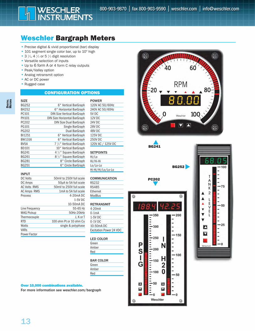
Weschler Bargraph Meters
CONFIGURATION OPTIONS
• Precise digital & vivid proportional (bar) display• 101 segment single color bar, up to 10" high• 3 1/2, 4 1/2 or 5 1/2 digit resolution• Versatile selection of inputs• Up to 6 form A or 4 form C relay outputs• Peak/Valley option• Analog retransmit option• AC or DC power• Rugged case
Over 10,000 combinations available.For more information see weschler.com/bargraph
SIZEBG252 6" Vertical BarGraphBH252 6" Horizontal BarGraphPC101 DIN Size Vertical BarGraphPH101 DIN Size Horizontal BarGraphPC202 DIN Size Dual BarGraphPG101 Single BarGraphPG202 Dual BarGraphBI1251 6" Vertical BarGraphBW1316 6" Vertical BarGraphBV5A 7 1/2" Vertical BarGraphBD101 10" Vertical BarGraphBG241 4 1/2" Square BarGraphBG261 8 1/2" Square BarGraphBG281 8" Circle BarGraphBG251 6" Circle BarGraph
INPUTDC Volts 50mV to 250V full scaleDC Amps 50µA to 5A full scaleAC Volts RMS 50mV to 250V full scaleAC Amps RMS 1mA to 5A full scaleProcess 4-20mA DC
1-5V DC 10-50mA DC
Line Frequency 55-65 HzMAG Pickup 50Hz-20kHzThermocouple J, K or TRTD 100 ohm Pt or 10 ohm CuWatts single & polyphaseVARsPower Factor
BG241
POWER120V AC 50/60Hz240V AC 50/60Hz5V DC12V DC24V DC28V DC48V DC125V DC250V DC120V AC / 125V DC
SETPOINTSHi/LoHi/Hi-HiLo/Lo-LoHi-Hi/Hi/Lo/Lo-Lo
COMMUNICATIONRS232RS485Ethernet ModBus
RETRANSMIT4-20mA 0-1mA1-5V DC0-1V DC10-50mA DC Excitation Power 24 VDC
LED COLORGreen Amber Red
BAR COLORGreen Amber Red
BG252
PC202

DIG
ITALM
ETERS
14
To Order—Insert Code for Each Letter to Select Catalog Number Order Example: BBVRR1RAY1VDL1BX
A Basic Unit Basic UnitBB BB101P BW BW051P BC BB202P (101 Segements each side)* BK BK051P
B Bargraph OrientationH Horizontal (BP101P Only) V Vertical
C Bargraph ColorA Amber R Red (Standard)G Green S Mixed (BW051/BK051 Only)
T TricolorD 4-Digit Display
X None G GreenA Amber R Red (Standard)
E Decimal Location1 000.0 3 0.0002 00.00 X 0000
F Setpoint Options (Must be ordered with Alarm Setpoint) (G)X None A Amber R Red (Standard) G Green
G Alarm Setpoint (Must be ordered with Setpoint Option (F)X None L Low/Low H High/High A High/Low
H Program SwitchesX None Y Yes (Standard)
I Primary Power1 115 VAC 4 24 VDC2 230 VAC 6 12 VDC5 5 VDC 8 48 VDC
J Signal InputsA Amperes M MilliamperesB Millivolts O OtherC Degrees C U MicroamperesF Degrees F V Volts
K Signal TypeA AC D DC O RTD or TC
L Signal LinearityL Linear Q Square RootX Non-linear (TC, RTD, custom)
M Special OptionsX None 1 Isolated 2-wire retransmit3 Auxiliary supply A AC/DC converter (for AC in)B DC amp (for <1V FS in) R RTD inJ Type J TC in K Type K TC inE Type E TC in S Combination of the above
N Bar StartB Bottom C CenterT Top
O Terminals/Conformal CoatingX Standard/none Y Standard/coatedB Barrier strip terminals E End capS Combination of the above
*Specify both sides for BB202P
L M
• Fit Standard Switchboard Cutouts
• Red, Green or Amber LED Bar
• Precise 4 Digit Readout
• Underrange/Overrange Indication
• On/Off Control via SetpointRelays
• Isolated Retransmit Option
• Transducer Excitation Supply
• Minimum 88,000 hour MTBF
• Two Year Warranty
Dixson Bargraph Meters/Controllers
SPECIFICATIONSInput Ranges:
DC Volts 50mV to 250V
DC Current 50mA to 250mA
AC Volts 250mV to 250V
AC Current 1mA to 5A
Thermocouple J, K, T, E
RTD Pt 100
DC Accuracy: ±0.04% of span ±1d
AC Accuracy: ±0.5% of span, above 5% of range
Digital Display: 4 digit LED, 0.01% resolution
Enclosure: Plastic, UL94 V0 or V1
Setpoint Relays: Form C, 0.4A@125VAC, 2A@30VDC
Setability: 0.1%, with 1.0% hysteresis
Operating temperature: 0 to 60°C
Power: 115/230VAC, 50/60/400Hz, 4VA/channel
DC power available
Line Regulation: ±10%
BB101P, BB202P Bar Segments: 101
Dimensions: 2.16"W x 6"H x 5.8"D
Panel Cutout: 1.77" x 5.7"
Orientation: Vertical or horizontal
BW051P Bar Segments: 51
Dimensions: 4.625" x 4.625" x 6.7"D
Panel Cutout: 4" dia ANSI switchboard
BK051P Bar Segments: 51
Dimensions: 3.82"W x 11.25"H x 7.10"D
Panel Cutout: 1.77" x 5.7"
BK051P
BW051P
ORDERING INFORMATION
A B C D E F J KG H I N O
DIG
ITAL
MET
ERS
15
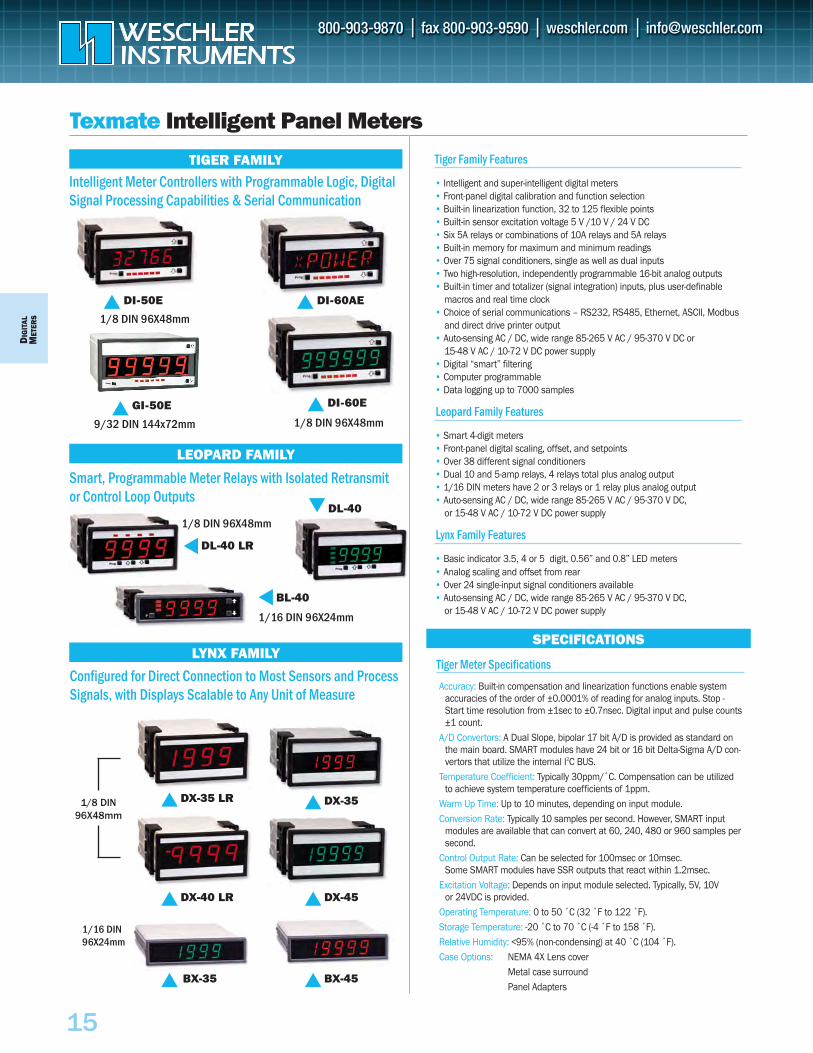
Texmate Intelligent Panel Meters
TIGER FAMILY
LEOPARD FAMILY
LYNX FAMILYSPECIFICATIONS
Intelligent Meter Controllers with Programmable Logic, DigitalSignal Processing Capabilities & Serial Communication
DI-50E
1/8 DIN 96X48mm
DI-60E
1/8 DIN 96X48mm
DL-40
GI-50E
9/32 DIN 144x72mm
DL-40 LR
1/8 DIN 96X48mm
1/16 DIN 96X24mm
1/8 DIN 96X48mm
1/16 DIN96X24mm
BL-40
DX-35DX-35 LR
DX-45DX-40 LR
BX-45BX-35
DI-60AE
Smart, Programmable Meter Relays with Isolated Retransmitor Control Loop Outputs
Configured for Direct Connection to Most Sensors and ProcessSignals, with Displays Scalable to Any Unit of Measure
Tiger Family Features
• Intelligent and super-intelligent digital meters• Front-panel digital calibration and function selection• Built-in linearization function, 32 to 125 flexible points• Built-in sensor excitation voltage 5 V /10 V / 24 V DC• Six 5A relays or combinations of 10A relays and 5A relays• Built-in memory for maximum and minimum readings• Over 75 signal conditioners, single as well as dual inputs• Two high-resolution, independently programmable 16-bit analog outputs• Built-in timer and totalizer (signal integration) inputs, plus user-definable
macros and real time clock• Choice of serial communications – RS232, RS485, Ethernet, ASCII, Modbus
and direct drive printer output• Auto-sensing AC / DC, wide range 85-265 V AC / 95-370 V DC or
15-48 V AC / 10-72 V DC power supply• Digital “smart” filtering• Computer programmable• Data logging up to 7000 samples
Leopard Family Features
• Smart 4-digit meters• Front-panel digital scaling, offset, and setpoints• Over 38 different signal conditioners• Dual 10 and 5-amp relays, 4 relays total plus analog output• 1/16 DIN meters have 2 or 3 relays or 1 relay plus analog output• Auto-sensing AC / DC, wide range 85-265 V AC / 95-370 V DC,
or 15-48 V AC / 10-72 V DC power supply
Lynx Family Features
• Basic indicator 3.5, 4 or 5 digit, 0.56” and 0.8” LED meters • Analog scaling and offset from rear• Over 24 single-input signal conditioners available• Auto-sensing AC / DC, wide range 85-265 V AC / 95-370 V DC,
or 15-48 V AC / 10-72 V DC power supply
Tiger Meter Specifications
Accuracy: Built-in compensation and linearization functions enable systemaccuracies of the order of ±0.0001% of reading for analog inputs. Stop -Start time resolution from ±1sec to ±0.7nsec. Digital input and pulse counts±1 count.
A/D Convertors: A Dual Slope, bipolar 17 bit A/D is provided as standard onthe main board. SMART modules have 24 bit or 16 bit Delta-Sigma A/D con-vertors that utilize the internal I2C BUS.
Temperature Coefficient: Typically 30ppm/˚C. Compensation can be utilizedto achieve system temperature coefficients of 1ppm.
Warm Up Time: Up to 10 minutes, depending on input module.Conversion Rate: Typically 10 samples per second. However, SMART input
modules are available that can convert at 60, 240, 480 or 960 samples persecond.
Control Output Rate: Can be selected for 100msec or 10msec. Some SMART modules have SSR outputs that react within 1.2msec.
Excitation Voltage: Depends on input module selected. Typically, 5V, 10V or 24VDC is provided.
Operating Temperature: 0 to 50 ˚C (32 ˚F to 122 ˚F).Storage Temperature: -20 ˚C to 70 ˚C (-4 ˚F to 158 ˚F).Relative Humidity: <95% (non-condensing) at 40 ˚C (104 ˚F).Case Options: NEMA 4X Lens cover
Metal case surroundPanel Adapters
DMIG
ITALETER
S
16
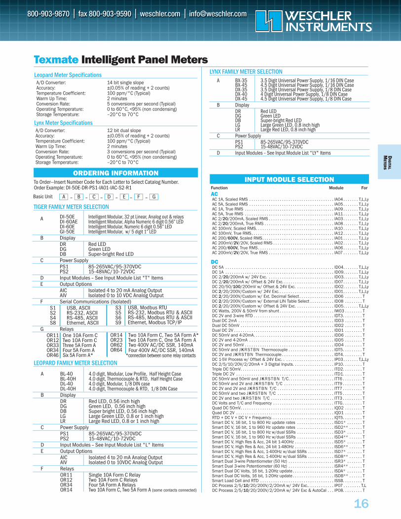
Texmate Intelligent Panel Meters
ORDERING INFORMATIONINPUT MODULE SELECTION
Leopard Meter SpecificationsA/D Converter: 14 bit single slopeAccuracy: ±(0.05% of reading + 2 counts)Temperature Coefficient: 100 ppm/°C (Typical)Warm Up Time: 2 minutesConversion Rate: 5 conversions per second (Typical)Operating Temperature: 0 to 60°C, <95% (non condensing)Storage Temperature: –20°C to 70°C
Lynx Meter SpecificationsA/D Converter: 12 bit dual slopeAccuracy: ±(0.05% of reading + 2 counts)Temperature Coefficient: 100 ppm/°C (Typical)Warm Up Time: 2 minutesConversion Rate: 3 conversions per second (Typical)Operating Temperature: 0 to 60°C, <95% (non condensing)Storage Temperature: –20°C to 70°C
TIGER FAMILY METER SELECTION
LEOPARD FAMILY METER SELECTION
LYNX FAMILY METER SELECTION
To Order—Insert Number Code for Each Letter to Select Catalog Number.Order Example: DI-50E-DR-PS1-IA01-IAC-S2-R1
A DI-50E Intelligent Modular, 32 pt Linear, Analog out & relaysDI-60AE Intelligent Modular, Alpha Numeric 6 digit 0.56” LEDDI-60E Intelligent Modular, Numeric 6 digit 0.56” LEDGI-50E Intelligent Modular, w/ 5 digit 1” LED
B DisplayDR Red LEDDG Green LEDDB Super-bright Red LED
C Power SupplyPS1 85-265VAC/95-370VDCPS2 15-48VAC/10-72VDC
D Input Modules – See Input Module List "T" ItemsE Output Options
AIC Isolated 4 to 20 mA Analog OutputAIV Isolated 0 to 10 VDC Analog Output
F Serial Communications (Isolated)S1S2S4S8
G RelaysOR11OR12OR33OR34OR46
A – B – C – D – E – F – GBasic Unit
A BL-40 4.0 digit, Modular, Low Profile, Half Height CaseBL-40H 4.0 digit, Thermocouple & RTD, Half Height CaseDL-40 4.0 digit, Modular, 1/8 DIN caseDL-40H 4.0 digit, Thermocouple & RTD, 1/8 DIN Case
B DisplayDR Red LED, 0.56 inch highDG Green LED, 0.56 inch highDB Super bright LED, 0.56 inch highLG Large Green LED, 0.8 or 1 inch highLR Large Red LED, 0.8 or 1 inch high
C Power SupplyPS1 85-265VAC/95-370VDCPS2 15-48VAC/10-72VDC
D Input Modules – See Input Module List "L" ItemsE Output Options
AIC Isolated 4 to 20 mA Analog OutputAIV Isolated 0 to 10VDC Analog Output
F RelaysOR11 Single 10A Form C RelayOR12 Two 10A Form C RelaysOR34 Four 5A Form A RelaysOR14 Two 10A Form C, Two 5A Form A (some contacts connected)
A BX-35 3.5 Digit Universal Power Supply, 1/16 DIN Case BX-45 4.5 Digit Universal Power Supply, 1/16 DIN CaseDX-35 3.5 Digit Universal Power Supply, 1/8 DIN CaseDX-40 4 Digit Universal Power Supply, 1/8 DIN CaseDX-45 4.5 Digit Universal Power Supply, 1/8 DIN Case
B DisplayDR Red LEDDG Green LEDDB Super-bright Red LEDLG Large Green LED, 0.8 inch highLR Large Red LED, 0.8 inch high
C Power SupplyPS1 85-265VAC/95-370VDCPS2 15-48VAC/10-72VDC
D Input Modules – See Input Module List "LY" Items
Function Module For
ACAC 1A, Scaled RMS . . . . . . . . . . . . . . . . . . . . . . . . . . . . . . . . . . . . . . . IA04 . . . . . . . T,L,LyAC 5A, Scaled RMS . . . . . . . . . . . . . . . . . . . . . . . . . . . . . . . . . . . . . . . IA05 . . . . . . . T,L,LyAC 1A, True RMS . . . . . . . . . . . . . . . . . . . . . . . . . . . . . . . . . . . . . . . . . IA09 . . . . . . . T,L,LyAC 5A, True RMS . . . . . . . . . . . . . . . . . . . . . . . . . . . . . . . . . . . . . . . . . IA11 . . . . . . . T,L,LyAC 2/20/200mA, Scaled RMS . . . . . . . . . . . . . . . . . . . . . . . . . . . . . . IA03 . . . . . . . T,L,LyAC 2/20/200mA, True RMS . . . . . . . . . . . . . . . . . . . . . . . . . . . . . . . . IA08 . . . . . . . T,L,LyAC 100mV, Scaled RMS. . . . . . . . . . . . . . . . . . . . . . . . . . . . . . . . . . . . IA10 . . . . . . . T,L,LyAC 100mV, True RMS. . . . . . . . . . . . . . . . . . . . . . . . . . . . . . . . . . . . . . IA12 . . . . . . . T,L,LyAC 200/600V, Scaled RMS. . . . . . . . . . . . . . . . . . . . . . . . . . . . . . . . . IA01 . . . . . . . T,L,LyAC 200mV/2V/20V, Scaled RMS . . . . . . . . . . . . . . . . . . . . . . . . . . . . IA02 . . . . . . . T,L,LyAC 200/600V, True RMS . . . . . . . . . . . . . . . . . . . . . . . . . . . . . . . . . . . IA06 . . . . . . . T,L,LyAC 200mV/2V/20V, True RMS . . . . . . . . . . . . . . . . . . . . . . . . . . . . . . IA07 . . . . . . . T,L,Ly
DCDC 5A . . . . . . . . . . . . . . . . . . . . . . . . . . . . . . . . . . . . . . . . . . . . . . . . . . ID04. . . . . . . T,L,LyDC 1A . . . . . . . . . . . . . . . . . . . . . . . . . . . . . . . . . . . . . . . . . . . . . . . . . . ID09. . . . . . . T,L,LyDC 2/20/200mA w/ 24V Exc. . . . . . . . . . . . . . . . . . . . . . . . . . . . . . . ID03. . . . . . . T,L,LyDC 2/20/200mA w/ Offset & 24V Exc. . . . . . . . . . . . . . . . . . . . . . . . ID07. . . . . . . T,L,LyDC 20/50/100/200mV w/ Offset & 24V Exc. . . . . . . . . . . . . . . . . . ID02. . . . . . . T,L,LyDC 2/20/200V/Custom w/ 24V Exc. . . . . . . . . . . . . . . . . . . . . . . . . . ID01. . . . . . . T,L,LyDC 2/20/200V/Custom w/ Ext. Decimal Select . . . . . . . . . . . . . . . . ID06 . . . . . . . . TDC 2/20/200V/Custom w/ External LIN Table Select . . . . . . . . . . . ID08 . . . . . . . . TDC 2/20/200V/Custom w/ Offset & 24V Exc. . . . . . . . . . . . . . . . . . ID05. . . . . . . T,L,LyDC Watts, 200V & 50mV from shunt . . . . . . . . . . . . . . . . . . . . . . . . . IW03 . . . . . . . . TDC 2V and 3-wire RTD . . . . . . . . . . . . . . . . . . . . . . . . . . . . . . . . . . . . . IDT3. . . . . . . . . TDual DC 2mA . . . . . . . . . . . . . . . . . . . . . . . . . . . . . . . . . . . . . . . . . . . . IDD3 . . . . . . . . TDual DC 50mV . . . . . . . . . . . . . . . . . . . . . . . . . . . . . . . . . . . . . . . . . . . IDD2 . . . . . . . . TDual DC 2V . . . . . . . . . . . . . . . . . . . . . . . . . . . . . . . . . . . . . . . . . . . . . . IDD1 . . . . . . . . TDC 50mV and 4-20mA. . . . . . . . . . . . . . . . . . . . . . . . . . . . . . . . . . . . . IDD6 . . . . . . . . TDC 2V and 4-20mA . . . . . . . . . . . . . . . . . . . . . . . . . . . . . . . . . . . . . . . IDD5 . . . . . . . . TDC 2V and 50mV . . . . . . . . . . . . . . . . . . . . . . . . . . . . . . . . . . . . . . . . . IDD4 . . . . . . . . TDC 50mV and JKRSTBN Thermocouple . . . . . . . . . . . . . . . . . . . . . IDT5. . . . . . . . . TDC 2V and JKRSTBN Thermocouple . . . . . . . . . . . . . . . . . . . . . . . . IDT4. . . . . . . . . TDC 1-5V Process w/ Offset & 24V Exc. . . . . . . . . . . . . . . . . . . . . . . . IP03. . . . . . . T,L,LyDC 2/5/10/20V/2/20mA + 3 Digital Inputs. . . . . . . . . . . . . . . . . . . IP10. . . . . . . . . TTriple DC 50mV. . . . . . . . . . . . . . . . . . . . . . . . . . . . . . . . . . . . . . . . . . . ITD2. . . . . . . . . TTriple DC 2V . . . . . . . . . . . . . . . . . . . . . . . . . . . . . . . . . . . . . . . . . . . . . ITD1. . . . . . . . . TDC 50mV and 50mV and JKRSTBN T/C. . . . . . . . . . . . . . . . . . . . . ITT6 . . . . . . . . . TDC 50mV and 2V and JKRSTBN T/C . . . . . . . . . . . . . . . . . . . . . . . ITT9 . . . . . . . . . TDC 2V and 2V and JKRSTBN T/C . . . . . . . . . . . . . . . . . . . . . . . . . . ITT7 . . . . . . . . . TDC 50mV and two JKRSTBN T/C . . . . . . . . . . . . . . . . . . . . . . . . . . ITT5 . . . . . . . . . TDC 2V and two JKRSTBN T/C . . . . . . . . . . . . . . . . . . . . . . . . . . . . . ITT3 . . . . . . . . . TDC Volts and T/C and Frequency . . . . . . . . . . . . . . . . . . . . . . . . . . . . ITTG . . . . . . . . . TQuad DC 50mV. . . . . . . . . . . . . . . . . . . . . . . . . . . . . . . . . . . . . . . . . . . IQD2 . . . . . . . . TQuad DC 2V . . . . . . . . . . . . . . . . . . . . . . . . . . . . . . . . . . . . . . . . . . . . . IQD1 . . . . . . . . TRTD + DC V + DC V + Frequency. . . . . . . . . . . . . . . . . . . . . . . . . . . . . IQT5. . . . . . . . . TSmart DC V, 16 bit, 1 to 800 Hz update rates . . . . . . . . . . . . . . . . . ISD1* . . . . . . . TSmart DC V, 16 bit, 1 to 960 Hz update rates . . . . . . . . . . . . . . . . . ISD2** . . . . . . TSmart DC V, 16 bit, 1 to 800 Hz w/dual SSRs . . . . . . . . . . . . . . . . . ISD3* . . . . . . . TSmart DC V, 16 bit, 1 to 960 Hz w/dual SSRs . . . . . . . . . . . . . . . . . ISD4** . . . . . . TSmart DC V, High Res & Acc, 24 bit 1-400Hz . . . . . . . . . . . . . . . . . . ISD5* . . . . . . . TSmart DC V, High Res & Acc, 24 bit 1-480Hz . . . . . . . . . . . . . . . . . . ISD6** . . . . . . TSmart DC V, High Res & Acc, 1-400Hz w/dual SSRs . . . . . . . . . . . . ISD7* . . . . . . . TSmart DC V, High Res & Acc, 1-400Hz w/dual SSRs . . . . . . . . . . . . ISD8** . . . . . . TSmart Dual 3-wire Potentiometer (50 Hz) . . . . . . . . . . . . . . . . . . . . . ISR3* . . . . . . . TSmart Dual 3-wire Potentiometer (60 Hz) . . . . . . . . . . . . . . . . . . . . . ISR4** . . . . . . TSmart Dual DC Volts, 16 bit, 1-20Hz update . . . . . . . . . . . . . . . . . . . ISDA* . . . . . . . TSmart Dual DC Volts, 16 bit, 1-20Hz update . . . . . . . . . . . . . . . . . . . ISDB** . . . . . . TSmart Load Cell and RTD . . . . . . . . . . . . . . . . . . . . . . . . . . . . . . . . . . ISSB. . . . . . . . . TDC Process 2/5/10/20/200V/2/20mA w/ 24V Exc.. . . . . . . . . . . . IP07 . . . . . . . . T,LDC Process 2/5/10/20/200V/2/20mA w/ 24V Exc & AutoCal . . . IP08. . . . . . . . . T
USB, Modbus RTURS-232, Modbus RTU & ASCIIRS-485, Modbus RTU & ASCIIEthernet, Modbus TCP/IP
USB, ASCIIRS-232, ASCIIRS-485, ASCIIEthernet, ASCII
S3S5S6S9
One 10A Form C Two 10A Form C Three 5A Form A Four 5A Form A Six 5A Form A*
OR14OR23OR62OR64
*connection between some relay contacts
Two 10A Form C, Two 5A Form A* Two 10A Form C, One 5A Form A Two 400V AC/DC SSR, 140mA Four 400V AC/DC SSR, 140mA

DIG
ITAL
MET
ERS
17
COUNTERQuadrature Counter . . . . . . . . . . . . . . . . . . . . . . . . IC02 . . . TQuadrature Counter w/dual SSRs. . . . . . . . . . . . . IC03 . . . TUniversal Freq./ RPM / Up Down Counter . . . . . . IF10 . . . TDual UP/DOWN Counter. . . . . . . . . . . . . . . . . . . . . IDC1. . . TCounter and T/C and 4-20mA . . . . . . . . . . . . . . . . ITTF . . . TSmart Dual Counter and Pressure Direct . . . . . . . ISP1 . . . T
DUAL INPUTS3-wire RTD and DC V . . . . . . . . . . . . . . . . . . . . . . . IDT3 . . . T3-wire RTD and 4-20mA . . . . . . . . . . . . . . . . . . . . . IDP2 . . . TDual DC 2mA. . . . . . . . . . . . . . . . . . . . . . . . . . . . . . IDD3. . . TDual DC 50mV . . . . . . . . . . . . . . . . . . . . . . . . . . . . IDD2. . . TDC 50mV and 4-20mA . . . . . . . . . . . . . . . . . . . . . . IDD6. . . TDC 2V and 4-20mA. . . . . . . . . . . . . . . . . . . . . . . . . IDD5. . . TDC 2V and DC 50mV . . . . . . . . . . . . . . . . . . . . . . . IDD4. . . TStrain Gage and Frequency . . . . . . . . . . . . . . . . . . IDS3 . . . TDual DC 2V . . . . . . . . . . . . . . . . . . . . . . . . . . . . . . . IDD1. . . TDual Direct Pressure (Abs. or Differential/Gage). . . IGYY . . . TDual Frequency . . . . . . . . . . . . . . . . . . . . . . . . . . . . IDF2 . . . TDual Pressure Input . . . . . . . . . . . . . . . . . . . . . . . . IDS2 . . . TDual Process Loop . . . . . . . . . . . . . . . . . . . . . . . . . IDP1 . . . TDual Resistance Input . . . . . . . . . . . . . . . . . . . . . . IDR1. . . TDual RTD Input . . . . . . . . . . . . . . . . . . . . . . . . . . . . IDT2 . . . TDual Smart Pressure/Load Cell, 16 bit. . . . . . . . . ISS5* . . TDual Smart Pressure/Load Cell, 16 bit. . . . . . . . . ISS6**. TDual Strain Gage Input. . . . . . . . . . . . . . . . . . . . . . IDS1 . . . TDual Thermocouple . . . . . . . . . . . . . . . . . . . . . . . . IDT1 . . . TThermocouple and 4-20mA . . . . . . . . . . . . . . . . . . IDP3 . . . TThermocouple and DC mV . . . . . . . . . . . . . . . . . . . IDT5 . . . TThermocouple and DC V . . . . . . . . . . . . . . . . . . . . IDT4 . . . TThermocouple and Load Cell . . . . . . . . . . . . . . . . . IDT6 . . . TDual UP/DOWN Counter. . . . . . . . . . . . . . . . . . . . . IDC1. . . TSmart Dual 3-wire Potentiometer . . . . . . . . . . . . . ISR3 . . . TSmart Load Cell and Process (4-20mA) . . . . . . . . . ISS9 . . . TSmart Dual DC Volts, 16 bit, 1-20Hz update . . . . ISDA* . . TSmart Dual DC Volts, 16 bit, 1-20Hz update . . . . ISD8**. TSmart Dual Photo Diode Input. . . . . . . . . . . . . . . . ISSE . . . TSmart Dual RTD (50Hz) . . . . . . . . . . . . . . . . . . . . . IST5* . . TSmart Dual RTD (60Hz) . . . . . . . . . . . . . . . . . . . . . IST6** . T
4 - 20mA3-wire RTD and 4-20mA . . . . . . . . . . . . . . . . . . . . . IDP2 . . . TDC 50mV and 4-20mA . . . . . . . . . . . . . . . . . . . . . . IDD6. . . TDC 2V and 4-20mA. . . . . . . . . . . . . . . . . . . . . . . . . IDD5. . . TDual Process Loop . . . . . . . . . . . . . . . . . . . . . . . . . IDP1 . . . TThermocouple and 4-20mA . . . . . . . . . . . . . . . . . . IDP3 . . . TProcess Loop 4-20mA . . . . . . . . . . . . . . . . . . . . . . IP01 . T,L,LyProcess Loop 4-20mA w/ Ext. Lin Table . . . . . . . IP09 . T,L,LyProcess Loop 4-20mA w/ 24V Exc. & AutoCal . . IP06 . . . TProcess Loop 4-20mA w/ 24V Exc. . . . . . . . . . . . IP02 . T,L,LyQuad 4-20mA . . . . . . . . . . . . . . . . . . . . . . . . . . . . . IQP1 . . . TSmart Load Cell and Process 4-20mA . . . . . . . . . . ISS9 . . . TTriple 4-20mA . . . . . . . . . . . . . . . . . . . . . . . . . . . . . ITP1 . . . T4-20mA and 4-20mA and T/C . . . . . . . . . . . . . . . . ITT8 . . . TT/C and 4-20mA and Counter . . . . . . . . . . . . . . . . ITTF . . . TT/C and 4-20mA and DC mV . . . . . . . . . . . . . . . . . ITTA . . . TT/C and 4-20mA and DC Volts . . . . . . . . . . . . . . . ITTB . . . TT/C and 4-20mA and Frequency . . . . . . . . . . . . . . ITTF . . . TT/C and T/C and 4-20mA . . . . . . . . . . . . . . . . . . . ITT4 . . . T
FREQUENCY / RPMUniversal Freq./ RPM / Up Down Counter . . . . . . IF10 . . . TUniversal Frequency / RPM . . . . . . . . . . . . . . . . . . IF05 . . . LLine Frequency . . . . . . . . . . . . . . . . . . . . . . . . . . . . IF08 . . . LLine Frequency . . . . . . . . . . . . . . . . . . . . . . . . . . . . IF06 . . . TDual Frequency . . . . . . . . . . . . . . . . . . . . . . . . . . . . IDF2 . . . TStrain Gage and Frequency . . . . . . . . . . . . . . . . . . IDS3 . . . TRTD and RTD and Frequency. . . . . . . . . . . . . . . . . ITTE . . . TT/C and 4-20mA and Frequency . . . . . . . . . . . . . . ITTF . . . TT/C and DC Volts and Frequency. . . . . . . . . . . . . . ITTG . . . TRTD + DC V + DC V + Frequency . . . . . . . . . . . . . . IQT5 . . . T
LVDTSmart Dual LVDT (50 Hz) . . . . . . . . . . . . . . . . . . . . ISL1* . . TSmart Dual LVDT (60 Hz) . . . . . . . . . . . . . . . . . . . . ISL2** . T
OXIDATION REDUCTION POTENTIALOxidation Reduction Potential (ORP). . . . . . . . . . . IOR1. . . T
pHpH. . . . . . . . . . . . . . . . . . . . . . . . . . . . . . . . . . . . . . . IH01 . . . TpH w/ Automatic Temperature Compensation . . . IH02. . . T
POTENTIOMETER3-wire Potentiometer 1kΩ min. . . . . . . . . . . . . . . . IR02 . T,L,LyLinear Potentiometer 1kΩ min . . . . . . . . . . . . . . . IR03 . . T,LSmart Dual 3-wire Potentiometer (50 Hz). . . . . . . ISR3*. . TSmart Dual 3-wire Potentiometer (60 Hz). . . . . . . ISR4**. TSmart Quad Potentiometer/Resistance . . . . . . . . ISSA . . . TSmart Single 3-wire Potentiometer (50 Hz) . . . . . ISR1*. . TSmart Single 3-wire Potentiometer (60 Hz) . . . . . ISR2**. T
PRESSURE / LOAD CELLUniversal Direct Pressure . . . . . . . . . . . . . . . . . . . . IGYZ . T,L,LyDirect Pressure with 2 Digital Inputs . . . . . . . . . . IGYX . . . TDual Direct Pressure (Abs. or Differential/Gage) . IGYY . . . TDual Pressure Input . . . . . . . . . . . . . . . . . . . . . . . . IDS2 . . . TDual Smart Pressure/Load Cell, 16 bit. . . . . . . . . ISS5* . . TDual Smart Pressure/Load Cell, 16 bit. . . . . . . . . ISS6**. TPressure/Load Cell 20/2mV/V, 5/10V Exc, 4-wire . . . . . . . . . . . . . . . . . . . . . . . . . . . . . . . . IS05 . T,L,LyPressure/Load Cell Ext Exc., 20/2mV/V, 4-wire. . IS06 . T,L,LyPressure/Load Cell Ext Exc., High Impedance . . . IS07 . . T,LPressure/Load Cell Ext Exc., 4/6-wire. . . . . . . . . . IS04 . . T,LPressure/Load Cell w/ AutoCal, 4-wire . . . . . . . . . IS03 . . . TPressure/Load Cell, 4/6-wire. . . . . . . . . . . . . . . . . IS02 . . T,LSmart Pressure/Load Cell, Standard Res 16 bit . ISS1* . . TSmart Pressure/Load Cell, Standard Res 16 bit . ISS2**. TSmart Pressure/Load Cell, High Res & Acc 24 bit . ISS3* . . TSmart Pressure/Load Cell, High Res & Acc 24 bit . ISS4** . TSmart Quad Pressure/Load Cell (50 Hz) . . . . . . . ISS7* . . TSmart Quad Pressure/Load Cell (60 Hz) . . . . . . . ISS8**. TSmart Pressure Direct & Dual Counter. . . . . . . . . . ISP1 . . . TSmart Load Cell and Process 4-20mA . . . . . . . . . . ISS9 . . . TSmart Load Cell and RTD. . . . . . . . . . . . . . . . . . . . ISSB . . . TSmart Load Cell and Two Digital Inputs . . . . . . . . . ISSC* . . TSmart Load Cell and Two Digital Inputs . . . . . . . . . ISSD**. TThermocouple and Load Cell . . . . . . . . . . . . . . . . . IDT6 . . . T
PROCESS LOOPDual Process Loop . . . . . . . . . . . . . . . . . . . . . . . . . IDP1 . . . TProcess Loop 4-20mA . . . . . . . . . . . . . . . . . . . . . . IP01 . T,L,LyProcess Loop 4-20mA w/ Ext. Lin Table . . . . . . . . . . IP09 . . . TProcess Loop 4-20mA w/ 24V Exc. & AutoCal. . . . . . IP06 . . . TProcess Loop 4-20mA w/ 24V DC Exc. . . . . . . . . IP02 . T,L,Ly
QUAD INPUTSQuad 4-20mA . . . . . . . . . . . . . . . . . . . . . . . . . . . . . IQP1 . . . TQuad DC 50mV . . . . . . . . . . . . . . . . . . . . . . . . . . . . IQD2. . . TQuad DC 2V. . . . . . . . . . . . . . . . . . . . . . . . . . . . . . . IQD1. . . TQuad RTD Platinum 2 wire connection. . . . . . . . . IQT2 . . . TQuad RTD Platinum 4 wire connection. . . . . . . . . IQT4 . . . TRTD + DC V + DC V + Frequency . . . . . . . . . . . . . . IQT5 . . . TSmart Quad Potentiometer/Resistance . . . . . . . . ISSA . . . TSmart Quad Pressure/Load Cell (50 Hz) . . . . . . . ISS7* . . TSmart Quad Pressure/Load Cell (60 Hz) . . . . . . . ISS8**. TSmart Quad Thermocouple (50 Hz) . . . . . . . . . . . IST3* . . TSmart Quad Thermocouple (60 Hz) . . . . . . . . . . . IST4** . T
RESISTANCEDual Resistance 0.2/2/20kΩ . . . . . . . . . . . . . . . . IDR1. . . TResistance 200/2k/20kΩ, 2/3/4-Wire . . . . . . . . IR01 . . . TResistance 2kΩ . . . . . . . . . . . . . . . . . . . . . . . . . . . IR04 . . . LResistance 2kΩ . . . . . . . . . . . . . . . . . . . . . . . . . . . IR05 . . LySmart Quad Potentiometer/Resistance . . . . . . . . ISSA . . . TSmart Voltage and Resistance . . . . . . . . . . . . . . . ISD9 . . . T
RTD3-wire RTD and DC V . . . . . . . . . . . . . . . . . . . . . . . IDT3 . . . T3-wire RTD and 4-20mA . . . . . . . . . . . . . . . . . . . . . IDP2 . . . TDual RTD . . . . . . . . . . . . . . . . . . . . . . . . . . . . . . . . . IDT2 . . . TQuad RTD Platinum 2 wire. . . . . . . . . . . . . . . . . . . IQT2 . . . TQuad RTD Platinum 4 wire. . . . . . . . . . . . . . . . . . . IQT4 . . . TRTD + DC V + DC V + Frequency . . . . . . . . . . . . . . IQT5 . . . TRTD, 10Ω Copper 2/3/4-wire . . . . . . . . . . . . . . . . IT13 . . . TRTD, 100Ω Pt. 2/3/4-wire . . . . . . . . . . . . . . . . . . . IT02 . . . TRTD, 100Ω Pt. 2/3/4-wire (-199.9 to 199.9˚C). . IT14 . T,L,LyRTD, 100Ω Pt. 2/3/4-wire (-199.9 to 199.9°F). . IT05 . T,L,LyRTD, 100Ω Pt. 2/3/4-wire (-200 to 800°C) . . . . . IT03 . T,L,LyRTD, 100Ω Pt. 2/3/4-wire (-200 to 1470°F) . . . . IT04 . T,L,LyRTD, 100Ω Pt. 3/4-wire, °C/°F, 1°/0.1°. . . . . . . IT11 . . . LRTD, 120Ω Nickel 2/3/4-wire . . . . . . . . . . . . . . . . IT12 . . . TRTD, 1000Ω Pt. Select 3/4-wire, °C/°F, 1°/0.1° . IT15 . . . LSmart Load Cell and RTD. . . . . . . . . . . . . . . . . . . . ISSB . . . TSmart Dual RTD (50Hz) . . . . . . . . . . . . . . . . . . . . . IST5* . . TSmart Dual RTD (60Hz) . . . . . . . . . . . . . . . . . . . . . IST6** . TSmart 6 Input - 3 RTD, 2 Process, 1 Digital . . . . . IST1* . . TSmart 6 Input - 3 RTD, 2 Process, 1 Digital . . . . . IST2** . TTriple RTD Platinum 100Ω, 4-wire . . . . . . . . . . . . . ITTC . . . T
Triple RTD Platinum 100Ω, 2-wire . . . . . . . . . . . . . ITT2 . . . TRTD and RTD and Frequency. . . . . . . . . . . . . . . . . ITTE . . . T
SINGLE PHASE POWERSingle Phase Power, 300V/1A. . . . . . . . . . . . . . . . IW01 . . TSingle Phase Power, 300V/5A. . . . . . . . . . . . . . . . IW02 . . TSingle Phase Power, 600V/1A. . . . . . . . . . . . . . . . IW04 . . TSingle Phase Power, 600V/5A. . . . . . . . . . . . . . . . IW05 . . T
STRAIN GAGEStrain Gage and Frequency . . . . . . . . . . . . . . . . . . IDS3 . . . TDual Strain Gage. . . . . . . . . . . . . . . . . . . . . . . . . . . IDS1 . . . TStrain Gage . . . . . . . . . . . . . . . . . . . . . . . . . . . . . . . IS01 . . T,L
THERMOCOUPLEDual Thermocouple JKRSTBN . . . . . . . . . . . . . . IDT1 . . . TT/C JKRSTBN and 4-20mA. . . . . . . . . . . . . . . . . IDP3 . . . TT/C JKRSTBN and DC 50mV . . . . . . . . . . . . . . . IDT5 . . . TT/C JKRSTBN and DC 2V . . . . . . . . . . . . . . . . . . IDT4 . . . TThermocouple and Load Cell . . . . . . . . . . . . . . . . . IDT6 . . . TSmart Quad Thermocouple (50 Hz) . . . . . . . . . . . IST3* . . TSmart Quad Thermocouple (60 Hz) . . . . . . . . . . . IST4** . TThermocouple JKRSTBN . . . . . . . . . . . . . . . . . . . IT01 . . . TT/C, JKRT, Selectable°C/°F, 1°/0.1° . . . . . . . . IT10 . . . LT/C JKRSTBN, 4-20mA and 4-20mA . . . . . . . . . ITT8 . . . TT/C JKRSTBN, 4-20mA and Counter. . . . . . . . . . ITTF . . . TT/C JKRSTBN, 4-20mA and DC 50mV. . . . . . . . ITTA . . . TT/C JKRSTBN, 4-20mA and DC 2V. . . . . . . . . . . ITTB . . . TT/C JKRSTBN, DC 50mV and DC 50mV . . . . . . ITT6 . . . TT/C JKRSTBN, DC 2V and DC 50mV . . . . . . . . . ITT9 . . . TT/C JKRSTBN, DC 2V and DC 2V . . . . . . . . . . . . ITT7 . . . TT/C JKRSTBN, T/C and 4-20mA. . . . . . . . . . . . . ITT4 . . . TT/C JKRSTBN, T/C and DC 50mV . . . . . . . . . . . ITT5 . . . TT/C JKRSTBN, T/C and DC 2V . . . . . . . . . . . . . . ITT3 . . . TT/C, 4-20mA and Frequency . . . . . . . . . . . . . . . . . ITTF . . . TT/C, DC Volts and Frequency . . . . . . . . . . . . . . . . . ITTG . . . TTriple Thermocouple JKRSTBN . . . . . . . . . . . . . ITT1 . . . T
TRIPLE INPUTSSmart Load Cell and Two Digital Inputs . . . . . . . . . ISSC* . . TSmart Load Cell and Two Digital Inputs . . . . . . . . . ISSD**. TSmart Pressure Direct & Dual Counter . . . . . . . . . . ISP1 . . . TTriple 4-20mA . . . . . . . . . . . . . . . . . . . . . . . . . . . . . ITP1 . . . TTriple DC 50mV . . . . . . . . . . . . . . . . . . . . . . . . . . . . ITD2 . . . TTriple DC 2V. . . . . . . . . . . . . . . . . . . . . . . . . . . . . . . ITD1 . . . TTriple RTD Platinum 100Ω, 4-wire . . . . . . . . . . . . . ITTC . . . TTriple RTD Platinum 100Ω, 2-wire . . . . . . . . . . . . . ITT2 . . . TRTD and RTD and Frequency. . . . . . . . . . . . . . . . . ITTE . . . TT/C JKRSTBN, 4-20mA and 4-20mA . . . . . . . . . ITT8 . . . TT/C JKRSTBN, 4-20mA and Counter. . . . . . . . . . ITTF . . . TT/C JKRSTBN, 4-20mA and DC 50mV. . . . . . . . ITTA . . . TT/C JKRSTBN, 4-20mA and DC 2V. . . . . . . . . . . ITTB . . . TT/C JKRSTBN, DC 50mV and DC 50mV . . . . . . ITT6 . . . TT/C JKRSTBN, DC 2V and DC 50mV . . . . . . . . . ITT9 . . . TT/C JKRSTBN, DC 2V and DC 2V . . . . . . . . . . . . ITT7 . . . TT/C JKRSTBN, T/C and 4-20mA. . . . . . . . . . . . . ITT4 . . . TT/C JKRSTBN, T/C and DC 50mV . . . . . . . . . . . ITT5 . . . TT/C JKRSTBN, T/C and DC 2V . . . . . . . . . . . . . . ITT3 . . . TT/C, 4-20mA and Frequency . . . . . . . . . . . . . . . . . ITTF . . . TT/C, Volts and Frequency . . . . . . . . . . . . . . . . . . . . ITTG . . . TTriple Thermocouple JKRSTBN . . . . . . . . . . . . . ITT1 . . . T
*Optimized for 50 Hz rejection. **Optimized for 60 Hz rejection.
Texmate Intelligent Panel Meters
ENHANCED TIGER FAMILY MODELS
DI-602ADual Display Meters
DI-802XDual Line Alphanumeric LCD
DI-503
Triple DisplayMeters
DI-50/AN6
Digital Meter withAnnunciators
Function Module For Function Module ForINPUT MODULE SELECTION - CONTINUEDFunction Module For
DMIG
ITALETER
S
18
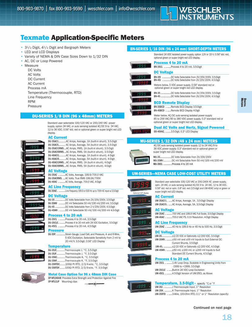
Standard user selectable 100/120 VAC or 200/240 VAC power supply, option 24 VAC, or auto sensing isolated AC/DC 9 to 24 VAC, 12 to 36 VDC. 0.56" std. red or optional green or super bright red LED display.
AC CurrentDU-35AC1….……..AC Amps, Average, 1A (built-in shunt), 3.5-DigitDU-35AC5……….. AC Amps, Average, 5A (built-in shunt), 3.5-DigitDU-35ACI1RMS….AC Amps, RMS, 1A (built-in shunt), 3.5-Digit DU-35ACI5RMS….AC Amps, RMS, 5A (built-in shunt), 3.5-DigitDU-40ACI1….…….AC Amps, Average, 1A (built-in shunt), 4-DigitDU-40ACI5………..AC Amps, Average, 5A (built-in shunt), 4-DigitDU-40ACI1RMS….AC Amps, RMS, 1A (built-in shunt), 4-Digit DU-40ACI5RMS….AC Amps, RMS, 5A (built-in shunt), 4-Digit
AC VoltageDU-35AC . ......AC Volts, Average, 199.9/700.0 VACDU-35ACRMS. ....AC Volts, True RMS 199.9V/700VDU-40AC . ......AC Volts, Average, 700.0 VAC, 4-Digit
AC Line FrequencyDU-35HZ . .......Line Frequency 199.9 or 500 Hz up to 700V AC input w/3.5-Digit
DC VoltageDU-35 ...........DC Volts Selectable from 2V/20V/200V, 3.5-DigitDU-35MV .......DC mV Selectable 50 mV/100 mV/200 mV, 3.5-DigitDU-45 ...........DC Volts Selectable from 2 V/20V/200V, 4.5-DigitDU-45MV . ......DC mV Selectable 50 mV/100 mV/200 mV 4.5-Digit
Process 4 to 20 mADU-35CL . ......Process 4 to 20 mA, 3.5-DigitDU-35CLE. ......Process 4 to 20 mA with 24 VDC Excitation, 3.5-DigitDU-45CL . ......Process 4 to 20 mA, 4.5-Digit
PressureDU-35P. .........Strain Gauge, Load Cell, and Pressure, 4- and 6-Wire,
5 VDC Excitation, Selectable Sensitivity from 2 mV to 20 mV/V, 3.5-Digit, 0.56" LED Display
TemperatureDU-35JC………....Thermocouple J, °C, 3.5-DigitDU-35JF……….….Thermocouple J, °F, 3.5-DigitDU-35KC………....Thermocouple K, °C, 3.5-DigitDU-35KF……….…Thermocouple K, °F, 3.5-DigitDU-35RTDC….…..100Ω Pt RTD, 2/3/4-wire, °C, 3.5-DigitDU-35RTDF………100Ω Pt RTD, 2/3/4-wire, °F, 3.5-Digit
Metal Case Option for 96 x 48mm DIN CaseOP-MTL96X48 Provides Extra Strength and Protection Against FireOP-MTLCLIP Mounting clips
Standard user selectable 100/120 VAC or 200/240V AC power supply,optn. 24 VAC, or auto sensing isolated AC/DC 9 to 24 VAC, 12 to 36 VDC.0.56" std. red or optn. 0.8" std. red (3.5-digit and UM-40AC only) or green or super bright red LED display.
AC CurrentUM-35ACI1. ....AC Amps, Average, 1A , 3.5-Digit DisplayUM-35ACI5. ....AC Amps, Average, 5A, 3.5-Digit Display
AC VoltageUM-35AC . ......700 VAC and 199.9 VAC Full Scale, 3.5-Digit DisplayUM-40AC . ......700.0 VAC FS, 0.1V Resolution, 4-Digit Display
AC Line FrequencyUM-35HZ . ......40 Hz to 199.9 Hz or 40 Hz to 500 Hz, 3.5-Digit
DC VoltageUM-35. ..........±2/20 VDC or Optionally ±2/200 VDC, 3.5-DigitUM-35MV . ......±50 mV and ±00 mV Inputs to Suit External DC
Current Shunts, 3.5-DigitUM-45. .........±2/20 VDC or Optionally ±2/200 VDC, 4.5-DigitUM-45MV . ......±50 mV, ±100 mV, or ±200 mV Inputs to Suit
Standard DC Current Shunts, 4.5-Digit
Process 4 to 20 mAUM-35CL . ......1.4V Loop Drop, Scalable in Engineering Units from
-1999 to +1999, 3.5-DigitUM-35CLE . ....Built-In 24 VDC Loop ExcitationUM-45CL . ......4.5-Digit Version of UM-35CL as Above
Temperature, 3.5-Digit - specify °C or °FUM-35J . ........J Thermocouple Input, 1° ResolutionUM-35K . ........K Thermocouple Input, 1° ResolutionUM-35RTD . ....3-Wire, 100-Ohm RTD, 0.1° or 1° Resolution (specify)
Standard 24 VDC isolated power supply, option 12V or 15 V. 0.56" std. red,optional green or super bright red LED display.
Process 4 to 20 mABN-35CL . ......Process 4 to 20 mA, 3.5-Digit
DC VoltageBN-35I . ........DC Volts Selectable from 2V/20V/200V, 3.5-DigitBN-45I . ........DC Volts Selectable from 2V/20V/200V, 4.5-Digit
Meters below, 5 VDC power supply. 0.56" standard red or optional green or super bright red LED display.
BN-35 ...........DC Volts Selectable from 2V/20V/200V, 3.5-DigitBN-45 ...........DC Volts Selectable from 2V/20V/200V, 4.5-Digit
BCD Remote DisplayBN-35BCD . ....Remote BCD Display 3.5-DigitBN-40BCD . ....Remote BCD Display 4-Digit
Meter below, AC/DC auto sensing isolated power supply 85 to 256 VAC/90 to 380 VDC power supply. 0.3" standard red oroptional green or super bright red LED display.
Dual AC Volts and Hertz, Signal PoweredDD-40VHZ. ......3.5-Digit, 0.3" LED Display
AC/DC auto sensing isolated power supply 12 to 24 VAC/9 to 36 VDC power supply. 0.3" standard red or optional green or super bright red LED display.
MU-35..................DC Volts Selectable from 2V/20V/200VMU-35MV..,..........DC mV Selectable from 50 mV/100 mV/200 mVMU-35CL . ........Process 4 to 20 mA
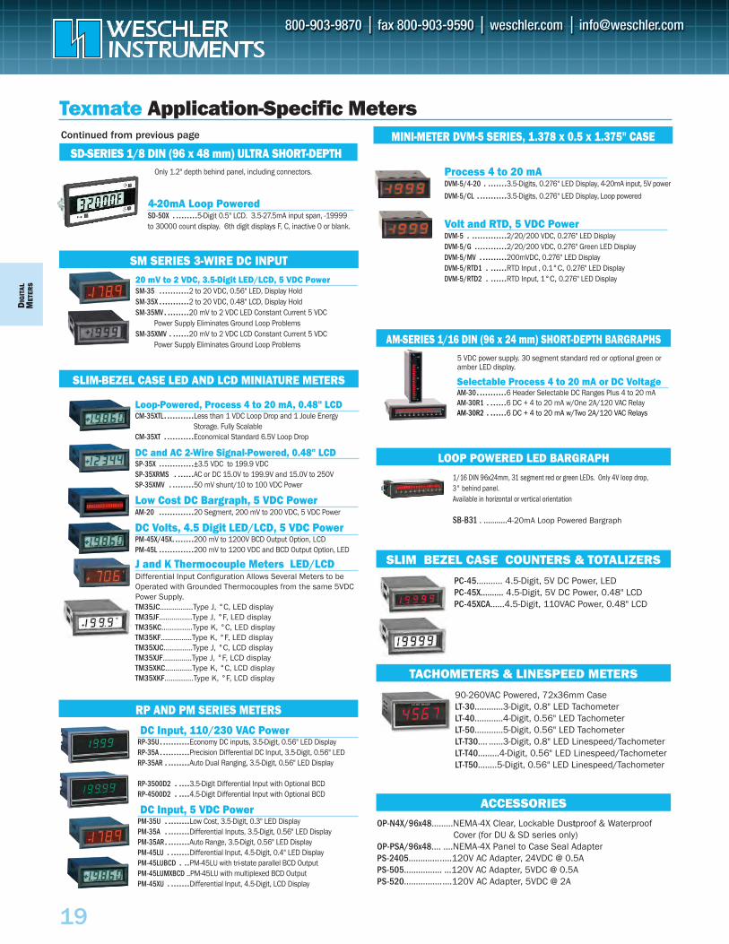
Texmate Application-Specific Meters
DU-SERIES 1/8 DIN (96 x 48mm) METERS
UM-SERIES—NEMA CASE LOW-COST UTILITY METERS
BN-SERIES 1/16 DIN (96 x 24 mm) SHORT-DEPTH METERS
MU-SERIES 1/32 DIN (48 x 24 mm) METERS
Optional 0.8" display
• 31/2 Digit, 41/2 Digit and Bargraph Meters• LED and LCD Displays• Variety of NEMA & DIN Case Sizes Down to 1/32 DIN• AC, DC or Loop Powered• Measure
DC VoltsAC VoltsDC CurrentAC CurrentProcess mATemperature (Thermocouple, RTD)Line FrequencyRPMPressure
Continued on next page
DIG
ITAL
MET
ERS
19
DC Input, 110/230 VAC PowerRP-35U...........Economy DC inputs, 3.5-Digit, 0.56" LED DisplayRP-35A ...........Precision Differential DC Input, 3.5-Digit, 0.56" LED RP-35AR . ........Auto Dual Ranging, 3.5-Digit, 0.56" LED Display
RP-3500D2 . ....3.5-Digit Differential Input with Optional BCDRP-4500D2 . ....4.5-Digit Differential Input with Optional BCD
DC Input, 5 VDC PowerPM-35U . ........Low Cost, 3.5-Digit, 0.3" LED DisplayPM-35A . ........Differential Inputs, 3.5-Digit, 0.56" LED DisplayPM-35AR. ........Auto Range, 3.5-Digit, 0.56" LED Display PM-45LU . .......Differential Input, 4.5-Digit, 0.4" LED DisplayPM-45LUBCD . ..PM-45LU with tri-state parallel BCD OutputPM-45LUMXBCD ..PM-45LU with multiplexed BCD OutputPM-45XU . .......Differential Input, 4.5-Digit, LCD Display
Texmate Application-Specific Meters MINI-METER DVM-5 SERIES, 1.378 x 0.5 x 1.375" CASE
RP AND PM SERIES METERS
SM SERIES 3-WIRE DC INPUT20 mV to 2 VDC, 3.5-Digit LED/LCD, 5 VDC PowerSM-35 ...........2 to 20 VDC, 0.56" LED, Display HoldSM-35X ...........2 to 20 VDC, 0.48" LCD, Display HoldSM-35MV. ........20 mV to 2 VDC LED Constant Current 5 VDC
Power Supply Eliminates Ground Loop Problems SM-35XMV . ......20 mV to 2 VDC LCD Constant Current 5 VDC
Power Supply Eliminates Ground Loop Problems
SLIM-BEZEL CASE LED AND LCD MINIATURE METERS
Loop-Powered, Process 4 to 20 mA, 0.48" LCDCM-35XTL...........Less than 1 VDC Loop Drop and 1 Joule Energy
Storage. Fully ScalableCM-35XT ...........Economical Standard 6.5V Loop Drop
DC and AC 2-Wire Signal-Powered, 0.48" LCDSP-35X .............±3.5 VDC to 199.9 VDC SP-35XRMS . ......AC or DC 15.0V to 199.9V and 15.0V to 250VSP-35XMV . ........50 mV shunt/10 to 100 VDC Power
Low Cost DC Bargraph, 5 VDC PowerAM-20 .............20 Segment, 200 mV to 200 VDC, 5 VDC Power
DC Volts, 4.5 Digit LED/LCD, 5 VDC PowerPM-45X/45X........200 mV to 1200V BCD Output Option, LCDPM-45L .............200 mV to 1200 VDC and BCD Output Option, LED
J and K Thermocouple Meters LED/LCDDifferential Input Configuration Allows Several Meters to beOperated with Grounded Thermocouples from the same 5VDCPower Supply.TM35JC……….……Type J, °C, LED displayTM35JF……….……Type J, °F, LED displayTM35KC……….…..Type K, °C, LED displayTM35KF……….…..Type K, °F, LED displayTM35XJC……….….Type J, °C, LCD displayTM35XJF……….….Type J, °F, LCD displayTM35XKC……….…Type K, °C, LCD displayTM35XKF……..……Type K, °F, LCD display
Process 4 to 20 mA DVM-5/4-20 . .......3.5-Digits, 0.276" LED Display, 4-20mA input, 5V power
DVM-5/CL ...........3.5-Digits, 0.276" LED Display, Loop powered
Volt and RTD, 5 VDC Power DVM-5 . .............2/20/200 VDC, 0.276" LED DisplayDVM-5/G ............2/20/200 VDC, 0.276" Green LED DisplayDVM-5/MV ..........200mVDC, 0.276" LED DisplayDVM-5/RTD1 . ......RTD Input , 0.1°C, 0.276" LED DisplayDVM-5/RTD2 . ......RTD Input, 1°C, 0.276" LED Display
LOOP POWERED LED BARGRAPH1/16 DIN 96x24mm, 31 segment red or green LEDs. Only 4V loop drop, 3" behind panel. Available in horizontal or vertical orientation
SB-B31 . ...........4-20mA Loop Powered Bargraph
5 VDC power supply. 30 segment standard red or optional green oramber LED display.
Selectable Process 4 to 20 mA or DC Voltage AM-30...........6 Header Selectable DC Ranges Plus 4 to 20 mAAM-30R1 . ......6 DC + 4 to 20 mA w/One 2A/120 VAC RelayAM-30R2 . ......6 DC + 4 to 20 mA w/Two 2A/120 VAC Relays
AM-SERIES 1/16 DIN (96 x 24 mm) SHORT-DEPTH BARGRAPHS
PC-45……..... 4.5-Digit, 5V DC Power, LEDPC-45X…....… 4.5-Digit, 5V DC Power, 0.48" LCDPC-45XCA…...4.5-Digit, 110VAC Power, 0.48" LCD
SLIM BEZEL CASE COUNTERS & TOTALIZERS
90-260VAC Powered, 72x36mm CaseLT-30……......3-Digit, 0.8" LED TachometerLT-40……...…4-Digit, 0.56" LED TachometerLT-50……......5-Digit, 0.56" LED TachometerLT-T30…. ......3-Digit, 0.8" LED Linespeed/TachometerLT-T40………4-Digit, 0.56" LED Linespeed/TachometerLT-T50……..5-Digit, 0.56" LED Linespeed/Tachometer
OP-N4X/96x48…......NEMA-4X Clear, Lockable Dustproof & Waterproof Cover (for DU & SD series only)
OP-PSA/96x48…. ....NEMA-4X Panel to Case Seal Adapter PS-2405…………......120V AC Adapter, 24VDC @ 0.5APS-505……………. ...120V AC Adapter, 5VDC @ 0.5APS-520…………….....120V AC Adapter, 5VDC @ 2A
ACCESSORIES
TACHOMETERS & LINESPEED METERS
SD-SERIES 1/8 DIN (96 x 48 mm) ULTRA SHORT-DEPTHOnly 1.2" depth behind panel, including connectors.
4-20mA Loop PoweredSD-50X . ........5-Digit 0.5" LCD. 3.5-27.5mA input span, -19999 to 30000 count display. 6th digit displays F, C, inactive 0 or blank.
Continued from previous page
DIG
ITALM
ETERS
20
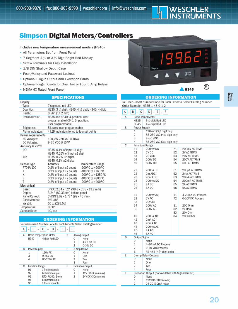
To Order—Insert Number Code for Each Letter to Select Catalog Number. Order Example: H335-1-46-0-1-2
A Basic Panel MeterH335 31/2 digit Red LEDH345 41/2 digit Red LED
B Power Supply1 120VAC (31/2 digit only)2 85-250 VAC (41/2 digit only)3 9–36 VDC4 85-250 VAC (31/2 digit only)
C Function/Range11 200mV DC 51 200mV AC TRMS12 2V DC 52 2V AC TRMS13 20 VDC 53 20V AC TRMS14 200V DC 54 200V AC TRMS15 600V DC 55 600 AC TRMS
21 200µA DC 61 200µA AC TRMS22 2m ADC 62 2mA AC TRMS23 20mA DC 63 20mA AC TRMS24 200mA DC 64 200mA AC TRMS25 2A DC 65 2A AC TRMS26 5A DC 66 5A AC TRMS
31 200mV AC 71 4-20mA DC Process32 2V AC 72 0-10V DC Process33 20V AC34 200V AC 81 200 Ohm35 600V AC 82 2k Ohm
83 20k Ohm41 200µA AC 84 200k Ohm42 2mA AC43 20mA AC44 200mA AC45 2A AC46 5A AC
D Output Signal0 None1 4–20 mA DC Process2 0–10 VDC Process6 RS-485 (4 1 /2 digit only)
E 5 Amp Relay Outputs0 None1 One2 Two4 Four
F Excitation Output (not available with Signal Output)0 None1 12V DC (30mA max)2 24 DC (30mA max)
SPECIFICATIONSDisplay
Type: 7 segment, red LEDQuantity: H335: 3 1/2 digit; H345: 4 1/2 digit; H340: 4 digitHeight: 0.56" (14.2 mm)Decimal Point: H335 and H340: 4-position, user
programmable H345: 5- position, user programmable
Brightness: 5 Levels, user programmableAlarm Indicators: 4 LED indicators for up to four set points
Power RequirementsAC Voltages: 120, 85-250 VAC @ 10VADC Voltages: 9–36 VDC @ 10 VA
Accuracy @ 25°C:DC: H335: 0.1% of input ±1 digit
H345: 0.05% of input ±1 digitAC: H335: 0.2% ±2 digits
H345: 0.1% ±2 digitsSensor Type Accuracy Temperature Range
RTD Pt 100 0.2% of input ±2 count -200°C to +200°CJ 0.2% of input ±2 counts -100°C to +760°CK 0.2% of input ±2 counts -200°C to +1250°CE 0.2% of input ±2 counts -100°C to +800°CT 0.2% of input ±2 counts -200°C to +400°C
MechanicalBezel: 3.93 x 2.04 x .52" (98.8 x 51.8 x 13.2 mm)Depth: 3.24" (82.33mm) behind panelPanel Cut-out: 1/8 DIN 3.62 x 1.77" (92 x 45 mm)Case Material: PBT-ABSWeight: 10 oz (283.5g)
Temperature: 0-50°CSample Rate: 10/sec
Simpson Digital Meters/Controllers
ORDERING INFORMATION
A – B – C – D – E – F
Includes new temperature measurement models (H340)
• All Parameters Set from Front Panel
• 7 Segment 4-1/2 or 3-1/2 Digit Bright Red Display
• Screw Terminals for Easy Installation
• 1/8 DIN Shallow Depth Case
• Peak/Valley and Password Lockout
• Optional Plug-In Output and Excitation Cards
• Optional Plug-In Cards for One, Two or Four 5 Amp Relays
• NEMA 4X Rated Front Panel
To Order—Insert Number Code for Each Letter to Select Catalog Number.
A Basic Temperature Meter D Analog OutputH340 4 digit Red LED 0 None
1 4-20 mA DC2 0-10V DC
B Power Supply E 5 Amp Relays1 120V AC 0 None3 9-36V DC 1 One4 85-250V AC 2 Two
4 FourC Function Range F Excitation Output
91 J Thermocouple 0 None92 K Thermocouple 1 12V DC (30mA max)93 RTD, Pt100, 3-wire 2 24V DC (30mA max)94 E Thermocouple95 T Thermocouple
ORDERING INFORMATION
A – B – C – D – E – F
H345
D IG
ITAL
M
ETER
S
21
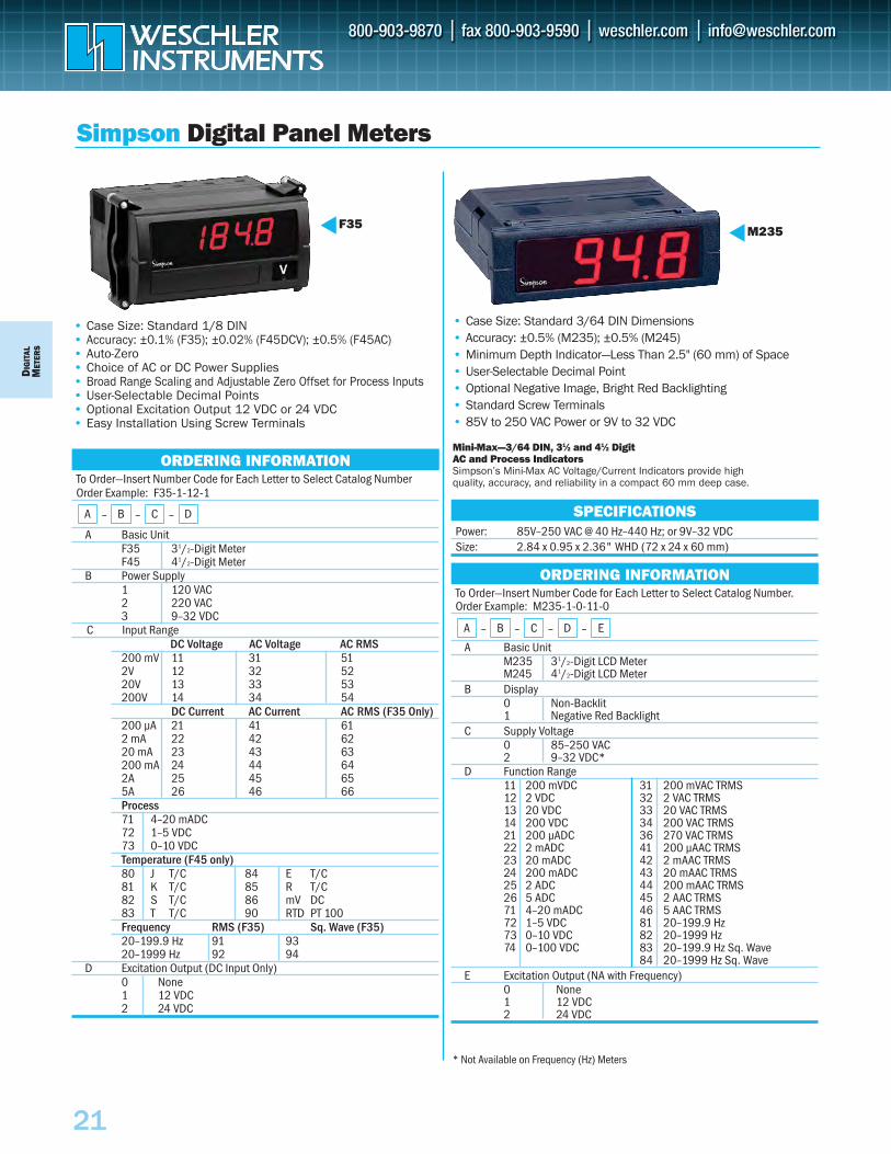
To Order—Insert Number Code for Each Letter to Select Catalog Number Order Example: F35-1-12-1
A Basic Unit F35 31/2-Digit Meter F45 41/2-Digit Meter
B Power Supply1 120 VAC 2 220 VAC 3 9–32 VDC
DC Voltage AC Voltage AC RMS200 mV 11 31 512V 12 32 5220V 13 33 53200V 14 34 54
DC Current AC Current AC RMS (F35 Only)200 µA 21 41 612 mA 22 42 6220 mA 23 43 63200 mA 24 44 642A 25 45 655A 26 46 66Process 71 4–20 mADC 72 1–5 VDC 73 0–10 VDC Temperature (F45 only) 80 J T/C 84 E T/C81 K T/C 85 R T/C82 S T/C 86 mV DC83 T T/C 90 RTD PT 100Frequency RMS (F35) Sq. Wave (F35) 20–199.9 Hz 91 93 20–1999 Hz 92 94
D Excitation Output (DC Input Only)0 None1 12 VDC2 24 VDC
ORDERING INFORMATION
A – B – C – D
Simpson Digital Panel Meters
F35• Case Size: Standard 1/8 DIN• Accuracy: ±0.1% (F35); ±0.02% (F45DCV); ±0.5% (F45AC)• Auto-Zero• Choice of AC or DC Power Supplies• Broad Range Scaling and Adjustable Zero Offset for Process Inputs • User-Selectable Decimal Points• Optional Excitation Output 12 VDC or 24 VDC• Easy Installation Using Screw Terminals
To Order—Insert Number Code for Each Letter to Select Catalog Number. Order Example: M235-1-0-11-0
A Basic Unit M235 31/2-Digit LCD Meter M245 41/2-Digit LCD Meter
B Display0 Non-Backlit 1 Negative Red Backlight
C Supply Voltage0 85–250 VAC 2 9–32 VDC*
D Function Range11 200 mVDC 31 200 mVAC TRMS 12 2 VDC 32 2 VAC TRMS 13 20 VDC 33 20 VAC TRMS 14 200 VDC 34 200 VAC TRMS21 200 µADC 36 270 VAC TRMS22 2 mADC 41 200 µAAC TRMS23 20 mADC 42 2 mAAC TRMS 24 200 mADC 43 20 mAAC TRMS 25 2 ADC 44 200 mAAC TRMS 26 5 ADC 45 2 AAC TRMS 71 4–20 mADC 46 5 AAC TRMS72 1–5 VDC 81 20–199.9 Hz73 0–10 VDC 82 20–1999 Hz 74 0–100 VDC 83 20–199.9 Hz Sq. Wave
84 20–1999 Hz Sq. Wave E Excitation Output (NA with Frequency)
0 None1 12 VDC2 24 VDC
• Case Size: Standard 3/64 DIN Dimensions• Accuracy: ±0.5% (M235); ±0.5% (M245)• Minimum Depth Indicator—Less Than 2.5" (60 mm) of Space• User-Selectable Decimal Point• Optional Negative Image, Bright Red Backlighting• Standard Screw Terminals• 85V to 250 VAC Power or 9V to 32 VDC
Mini-Max—3/64 DIN, 31⁄2 and 41⁄2 Digit AC and Process Indicators Simpson’s Mini-Max AC Voltage/Current Indicators provide high quality, accuracy, and reliability in a compact 60 mm deep case.
Power: 85V–250 VAC @ 40 Hz–440 Hz; or 9V–32 VDC Size: 2.84 x 0.95 x 2.36" WHD (72 x 24 x 60 mm)
SPECIFICATIONS
M235
ORDERING INFORMATION
A – B – C – D – E
* Not Available on Frequency (Hz) Meters
C Input Range
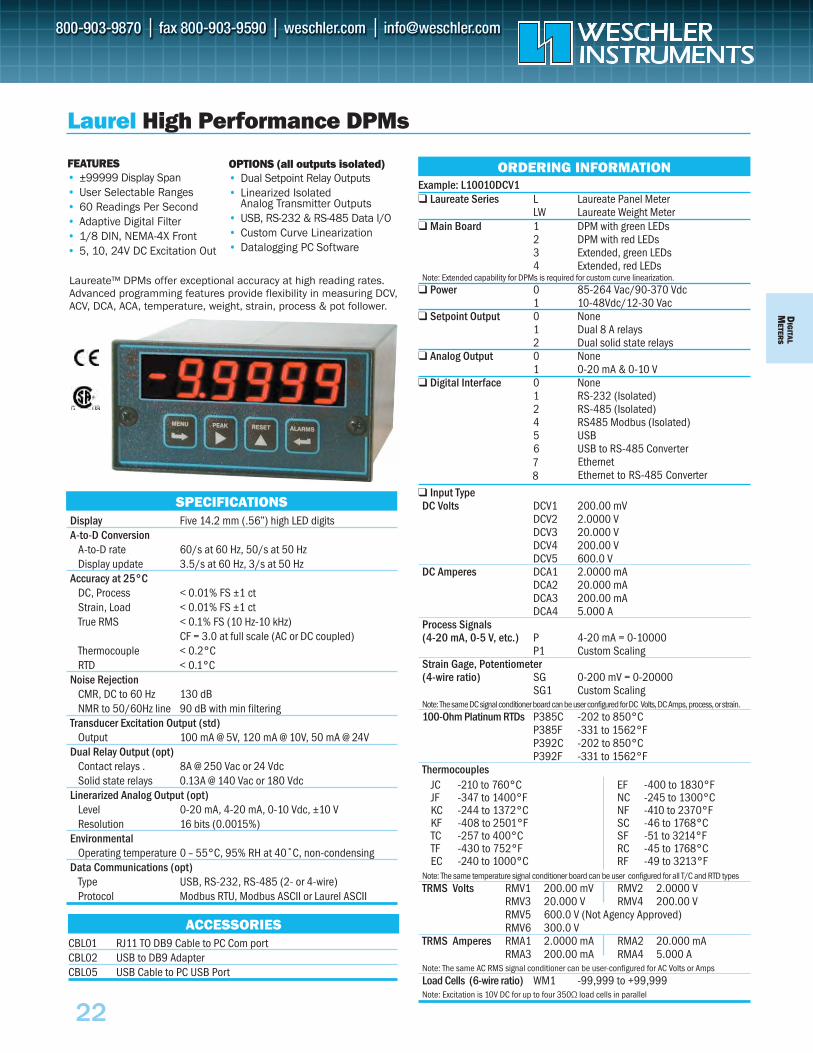
Example: L10010DCV1 Laureate Series L Laureate Panel Meter
LW Laureate Weight Meter Main Board 1 DPM with green LEDs
2 DPM with red LEDs3 Extended, green LEDs4 Extended, red LEDs
Note: Extended capability for DPMs is required for custom curve linearization. Power 0 85-264 Vac/90-370 Vdc
1 10-48Vdc/12-30 Vac Setpoint Output 0 None
1 Dual 8 A relays 2 Dual solid state relays
Analog Output 0 None 1 0-20 mA & 0-10 V
Digital Interface 0 None 1 RS-232 (Isolated) 2 RS-485 (Isolated) 4 RS485 Modbus (Isolated) 5 USB 6 USB to RS-485 Converter
Input Type DC Volts DCV1 200.00 mV
DCV2 2.0000 V DCV3 20.000 V DCV4 200.00 V DCV5 600.0 V
DC Amperes DCA1 2.0000 mA DCA2 20.000 mA DCA3 200.00 mA DCA4 5.000 A
Process Signals (4-20 mA, 0-5 V, etc.) P 4-20 mA = 0-10000
P1 Custom Scaling Strain Gage, Potentiometer (4-wire ratio) SG 0-200 mV = 0-20000
SG1 Custom ScalingNote: The same DC signal conditioner board can be user configured for DC Volts, DC Amps, process, or strain.100-Ohm Platinum RTDs P385C -202 to 850°C
P385F -331 to 1562°F P392C -202 to 850°C P392F -331 to 1562°F
Thermocouples
Note: The same temperature signal conditioner board can be user configured for all T/C and RTD typesTRMS Volts RMV1 200.00 mV RMV2 2.0000 V
RMV3 20.000 V RMV4 200.00 V RMV5 600.0 V (Not Agency Approved) RMV6 300.0 V
TRMS Amperes RMA1 2.0000 mA RMA2 20.000 mARMA3 200.00 mA RMA4 5.000 A
Note: The same AC RMS signal conditioner can be user-configured for AC Volts or AmpsLoad Cells (6-wire ratio) WM1 -99,999 to +99,999Note: Excitation is 10V DC for up to four 350Ω load cells in parallel
DMIG
ITALETER
S
Laureate™ DPMs offer exceptional accuracy at high reading rates. Advanced programming features provide flexibility in measuring DCV, ACV, DCA, ACA, temperature, weight, strain, process & pot follower.
Laurel High Performance DPMs
FEATURES• ±99999 Display Span• User Selectable Ranges• 60 Readings Per Second• Adaptive Digital Filter• 1/8 DIN, NEMA-4X Front• 5, 10, 24V DC Excitation Out
Display Five 14.2 mm (.56”) high LED digits A-to-D Conversion
A-to-D rate 60/s at 60 Hz, 50/s at 50 Hz Display update 3.5/s at 60 Hz, 3/s at 50 Hz
Accuracy at 25°CDC, Process < 0.01% FS ±1 ct Strain, Load < 0.01% FS ±1 ct True RMS < 0.1% FS (10 Hz-10 kHz)
CF = 3.0 at full scale (AC or DC coupled) Thermocouple < 0.2°C RTD < 0.1°C
Noise RejectionCMR, DC to 60 Hz 130 dB NMR to 50/60Hz line 90 dB with min filtering
Transducer Excitation Output (std)Output 100 mA @ 5V, 120 mA @ 10V, 50 mA @ 24V
Dual Relay Output (opt)Contact relays . 8A @ 250 Vac or 24 Vdc Solid state relays 0.13A @ 140 Vac or 180 Vdc
Linerarized Analog Output (opt)Level 0-20 mA, 4-20 mA, 0-10 Vdc, ±10 V Resolution 16 bits (0.0015%)
EnvironmentalOperating temperature 0 – 55°C, 95% RH at 40˚C, non-condensing
Data Communications (opt)Type USB, RS-232, RS-485 (2- or 4-wire) Protocol Modbus RTU, Modbus ASCII or Laurel ASCII
SPECIFICATIONS
ORDERING INFORMATION
JC -210 to 760°C JF -347 to 1400°F KC -244 to 1372°C KF -408 to 2501°F TC -257 to 400°C TF -430 to 752°F EC -240 to 1000°C
EF -400 to 1830°F NC -245 to 1300°C NF -410 to 2370°F SC -46 to 1768°C SF -51 to 3214°F RC -45 to 1768°C RF -49 to 3213°F
ACCESSORIESCBL01 RJ11 TO DB9 Cable to PC Com port CBL02 USB to DB9 Adapter CBL05 USB Cable to PC USB Port
OPTIONS (all outputs isolated)• Dual Setpoint Relay Outputs• Linearized Isolated
Analog Transmitter Outputs• USB, RS-232 & RS-485 Data I/O• Custom Curve Linearization• Datalogging PC Software
EthernetEthernet to RS-485 Converter
22
78
D IG
ITAL
M
ETER
S
23
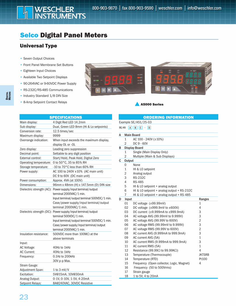
Selco Digital Panel Meters
• Seven Output Choices
• Front Panel Membrane Set Buttons
• Eighteen Input Choices
• Available Two Setpoint Displays
• 90-264VAC or 9-60VDC Power Supply
• RS-232C/RS-485 Communications
• Industry Standard 1/8 DIN Size
• 8-Amp Setpoint Contact Relays
Universal Type
Main display: 4 Digit Red LED 14.2mm Sub display: Dual, Green LED 8mm (Hi & Lo setpoints) Conversion rate: 12.5 times/sec Maximum display: 9999 Overrange indication: When input exceeds the maximum display,
display OL or -OL Zero display: Leading zero suppression Decimal point: Settable to any digit position External control: Start/Hold, Peak Hold, Digital Zero Operating temperature: 0 to 50°C, 35 to 85% RH Storage temperature: -10 to 70°C less than 60% RH Power supply: AC 100 to 240V ±10% (AC main unit)
DC 9 to 60V (DC main unit)Power consumption: Approx. 4VA (at 100V) Dimensions: 96mm x 48mm (H) x 147.5mm (D) DIN size Dielectric strength (AC): Power supply/input terminal/output
terminal 2000VAC/1 min.Input terminal/output terminal 500VDC/1 min. Case/power supply/input terminal/output terminal 2000VAC/1 min.
Dielectric strength (DC): Power supply/input terminal/output terminal 500VDC/1 min.Input terminal/output terminal 500VDC/1 min. Case/power supply/input terminal/output terminal 2000VAC/1 min.
Insulation resistance: 500VDC more than 100MΩ at the above terminals
Input: AC Voltage: 40Hz to 1kHz AC Current: 40Hz to 1kHz Frequency: 0.1Hz to 200kHz
30V p-p Max.Strain Gauge: Adjustment Span: 1 to 3 mV/V Excitation: 5V@15mA, 10V@30mA Analog Output: 0-1V, 0-10V, 1-5V, 4-20mA Setpoint Relays: 8A@240VAC, 30VDC Resistive
Example SE/A51/25-03
A Main Board1 AC 100 - 240V (±10%)2 DC 9 - 60V
B Display Board1 Single (Main Display Only)2 Multiple (Main & Sub Displays)
C Output0 None1 HI & LO setpoint2 Analog output3 RS-232C4 RS-485 5 HI & LO setpoint + analog output 6 HI & LO setpoint + analog output + RS-232C 7 HI & LO setpoint + analog output + RS-485
D Input Ranges01 DC voltage (±99.99mV) 102 DC voltage (±999.9mV to ±600V) 403 DC current (±9.999mA to ±999.9mA) 304 AC voltage AVG (99.99mV to 9.999V) 305 AC voltage AVG (99.99V to 600V) 206 AC voltage RMS (99.99mV to 9.999V) 307 AC voltage RMS (99.99V to 600V) 208 AC current AVG (9.999mA to 999.9mA) 309 AC current AVG (5A) 110 AC current RMS (9.999mA to 999.9mA) 311 AC current RMS (5A) 112 Resistance (99.99Ω to 99.99KΩ) 413 Temperature (Thermocouple) JKTSRB14 Temperature (RTD) Pt10015 Frequency (Open collector, Logic, Magnet) 416 Frequency (50 to 500Vrms)17 Strain gauge 18 1 to 5V, 4 to 20mA
SE/A5 A B C - D
SPECIFICATIONS ORDERING INFORMATION
A5000 Series
23a
To Order—Insert Number Code for Each Letter to Select Catalog Number. Order Example: IDP-0
A Basic Unit IDP 4-Digit Process Meter $195IDT 4-Digit Thermocouple Meter $225 IDpH 4-Digit pH Meter $245
B Display/Power 0 Red/115 VAC N/C1 Red/230 VAC2 Green/115 VAC3 Green/230 VAC4 Red/10–32 VDC5 Green/10–32 VDC
To Order—Insert Number Code for Each Letter to Select Catalog Number. Order Example: INFCAC-0-0-1-0-V5
A Basic Unit INFCAC AC Voltage and Current Controller $ B Power and LED Color 0 115 VAC, Red LED Display N/C 1 230 VAC, Red LED Display 2 115 VAC, Green LED Display N/C3 230 VAC, Green LED Display N/C C Control Output 0 No Control Output N/C1 Two 6A Form “C” Relays$ 70D Analog Output 0 No Analog Output N/C1 4 to 20 mA or 0 to 10 VDC$ 80E Communications 0 No Serial Output N/C1 Isolated RS-232 $1102 Isolated RS-485 Half Duplex$ 110F Input Signal V5 0–750 VAC User Programmable N/CC5 0–5 AAC User Programmable N/C
To Order—Insert Number Code for Each Letter to Select Catalog Number. Order Example: INFCP-5-1-2
A Basic Unit INFCP Process (DC Voltage and Current)INFCS Strain Input NIFCT Thermocouple INFCDT Dual/Differential Thermocouple INFCR RTD INFCDR Dual/Differential RTD INFCPH pH INFCOR ORP INFCOP pH/ORP
B Power and Display0 115 VAC, Red LED Display N/C1 230 VAC, Red LED Display 2 115 VAC, Green LED Display 3 230 VAC, Green LED Display 4 10–32 VDC, Red LED Display 5 10–32 VDC, Green LED Display 6 25–56 VDC, Red LED Display 7 25–56 VDC, Green LED Display
C Relays0 None N/C1 Two 6 Amp Form C Relays $ 70
D Analog Output 0 None N/C1 Non-Isolated Analog $ 802 Isolated Analog Output $ 90
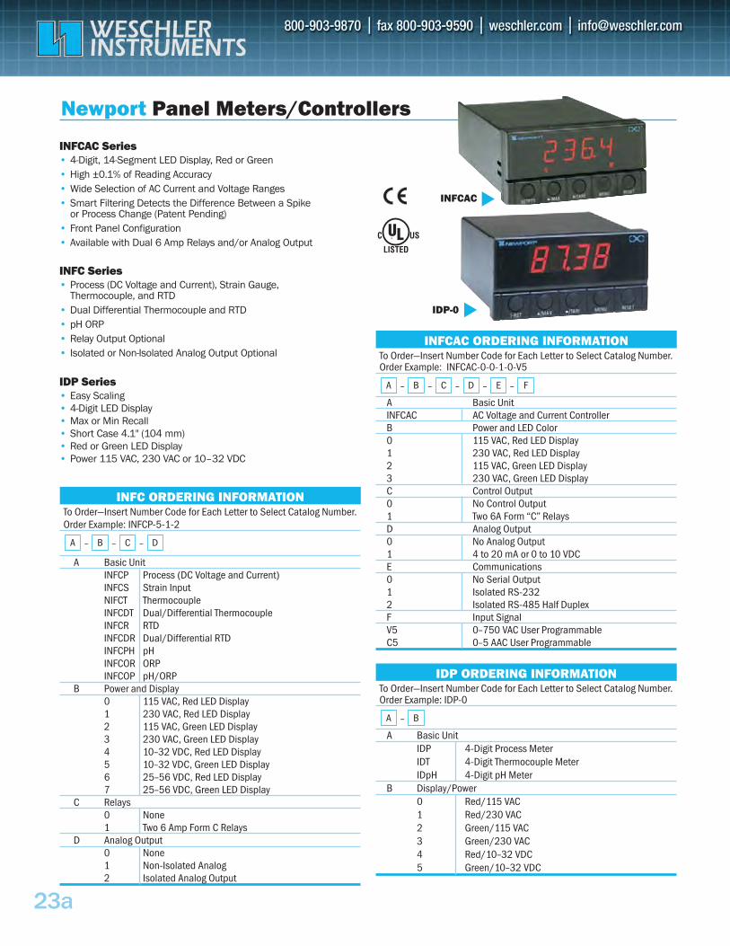
INFCAC Series• 4-Digit, 14-Segment LED Display, Red or Green• High ±0.1% of Reading Accuracy• Wide Selection of AC Current and Voltage Ranges• Smart Filtering Detects the Difference Between a Spike
or Process Change (Patent Pending)• Front Panel Configuration• Available with Dual 6 Amp Relays and/or Analog Output
INFC Series• Process (DC Voltage and Current), Strain Gauge,
Thermocouple, and RTD• Dual Differential Thermocouple and RTD• pH ORP• Relay Output Optional• Isolated or Non-Isolated Analog Output Optional
IDP Series• Easy Scaling• 4-Digit LED Display• Max or Min Recall• Short Case 4.1" (104 mm)• Red or Green LED Display• Power 115 VAC, 230 VAC or 10–32 VDC
Newport Panel Meters/Controllers
INFCAC ORDERING INFORMATION
A – B – C – D – E – F
IDP ORDERING INFORMATION
A – B
INFC ORDERING INFORMATION
A – B – C – D
INFCAC
IDP-0
23b
To Order—Insert Number Code for Each Letter to Select Catalog Number. Order Example: INFP-0210-C2
A Basic Unit INFP Process (DC Voltage and Current) $ 545INFS Strain Gauge $ 545INFW Weight $ 595INFT Thermocouple and RTD $ 595INFU Universal Input (Process, Strain and Temp.) $ 645
B Split Display–Insert Only If RequiredZ Split Display (insert “Z” after INF in basic unit) $
C Power and Display0 115 VAC, Red LED N/C1 230 VAC, Red LED N/C2 115 VAC, Green LED N/C3 230 VAC, Green LED N/C4 10–32 VDC, Red LED $ 1105 10–32 VDC, Green LED $ 110
D Control Output 0 Four NPN Open Collectors N/C1 Isolated Parallel BCD $ 1102 Two 7A Relays $ 753 Two 7A Relays and Two 1A Relay $ 175
E Analog Output 0 None N/C1 Isolated Analog Output $ 110
F Serial Output 0 None N/C1 Isolated RS-232 $ 1102 Isolated RS-485 $ 110
G Input SignalSpecify T/C, RTD type or DC range N/C
To Order—Insert Number Code for Each Letter to Select Catalog Number. Order Example: i822-0-DC
A Base Units i800 Monitor only (no control outputs) 1/8 DIN $ 240i8C00 Monitor only (no control outputs) 1/8 DIN Short Case $ i8A00 Monitor with Isolated Analog Output 1/8 DIN $ 295i8 Two control outputs 1/8 DIN $ 310i8C Two control outputs 1/8 DIN Short Case $ 355i8A Isolated Analog Output with two control outputs 365
B Control Output #1 & #2 Direct (Cool) or Reverse (Heat) Acting22 Two solid state relays (SSR’s) N/C23 SSR and relay: Form “C” SPDT N/C24 SSR and pulsed 10 Vdc(for use with external SSR) 33 2 Relays: Form “C” SPDT N/C34 Relay and pulsed (for use with external SSR) N/C 44 Two pulsed 10 Vdc (for use with external SSR) N/C 52 Analog Output (control or retransmission) N/C 53 Analog Output and Relay N/C54 Analog Outputand Pulse N/C
C Network Options E1 Ethernet with Embedded Web Server 2 $ 55C24 Isolated RS-232 and RS-485 (MODBUS & ASCII) $0 C4EI Ethernet with Embedded Internet + Isolated RS-485 2 $
D Power SupplyAC Standard Power : 90 to 240 VAC/DC N/C DC 10-34 Vac/dc (optional) $ 25
111 Not Available for the i8A Controller222 Not Available in the Short Case
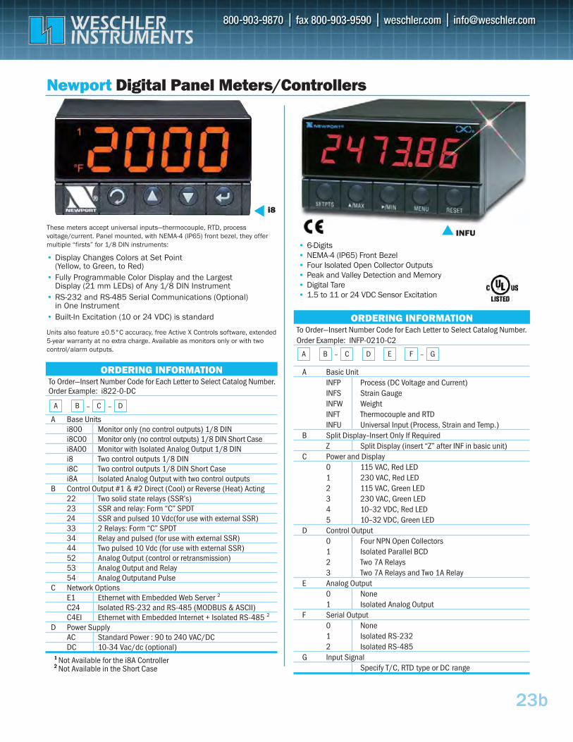
These meters accept universal inputs—thermocouple, RTD, process voltage/current. Panel mounted, with NEMA-4 (IP65) front bezel, they offer multiple “firsts” for 1/8 DIN instruments:
• Display Changes Colors at Set Point (Yellow, to Green, to Red)
• Fully Programmable Color Display and the Largest Display (21 mm LEDs) of Any 1/8 DIN Instrument
• RS-232 and RS-485 Serial Communications (Optional) in One Instrument
• Built-In Excitation (10 or 24 VDC) is standard
Units also feature ±0.5°C accuracy, free Active X Controls software, extended 5-year warranty at no extra charge. Available as monitors only or with two control/alarm outputs.
Newport Digital Panel Meters/Controllers
• 6-Digits• NEMA-4 (IP65) Front Bezel• Four Isolated Open Collector Outputs• Peak and Valley Detection and Memory• Digital Tare• 1.5 to 11 or 24 VDC Sensor Excitation
i8
ORDERING INFORMATION
A B – C – D
INFU
ORDERING INFORMATION
A B – C D E F – G

DIG
ITALM
ETERS
• 1/8 DIN, IP65 Front• Large 0.55" LED Display• Simplified Setup – No Menus• Display Filtering • 10-Point Custom Linearization• 0.05% Basic DC Accuracy• Variable Brightness Display
Input types to match common sensors & process signals.
London Electronics Programmable Meter
Intuitive 2
ORDERING INFORMATION
INT2- A – B – C – D – E – F
®
To Order—Insert Number Code for Each Letter to Select Catalog Number. Order Example: INT2-P-0-0-232-R-AC
A Input TypeP DC Process: 0-10V, 1-5V, 0-10mA, 4-20mAM Millivolt Input for use with DC shuntsT Temperature: J K T R S N & Pt100, °F & °CR 4-Wire Resistance: specify range to 20kΩL Load Cell: 4/6-wire, w/ 10V excitationI Flow Integrator: 0-10V, 4-20mAH Clock/Timer, numeric or HH:MM:SS displayC Counter/Frequency/RPM/QuadratureS Remote Display, serial ASCII data input
B Analog Output (Isolated)0 None ANV 0–10VANI 4–20 mA ANB -10 to +10V
C Relay Output (2A@250 VAC)0 None AL4 4 Form AAL2 2 Form A SPCO 2 Form C
D Serial Data Output0 None232 RS-232 MB RS-485 ModBus RTU485 RS-485, ASCII EN Ethernet
E Display ColorR Red Y YellowG Green
F Supply VoltageAC 100-240 VACDC 11–30 VDC
A Input VoltageL 57.7-139 L-N (100-240 L-L)M 140-277 L-N (241-480 L-L)
B Input Current (CT secondary)5 5A1 1A
C Auxiliary VoltageL 12-48 V DCM 100–250V AC/DC
D Options000 None010 RS-485 Modbus RTU100 One Pulse200 Two Pulse210 Two Pulse & Modbus110 One Pulse & Modbus070 Ethernet Modbus TCP
• 35 Measured Parameters• 0.2% Basic Accuracy• Field Selectable CT & PT Ratios• Ethernet or RS-485 Interface• 1/4 DIN Case
The Integra 1630 has Modbuscommunication and field selec-table system configuration: single-phase, three-phase three-wire or three-phase four-wire.
•• Frequency•• Power factor (overall)•• kVAr, kVA, kW•• kW Hr import, export (7 digits)•• kVArh import, export (7 digits)•• kW demand•• Current demand•• Maximum kW demand •• Maximum current demand•• Hours run
Crompton Digital Metering System
SPECIFICATIONS ORDERING INFORMATION1630
Measure & Display•• System (average) volts•• System (average) current•• System (total) kW•• System volts (average) THD%•• System current (average) THD%•• Volts L1 – N, L2 – N, L3 – N•• Volts L1 – L2, L2 – L3, L3 – L1•• Volts L1 – N THD%•• Volts L2 – N THD%
•• Volts L3 – N THD%•• Volts L1 – L2 THD%•• Volts L2 – L3 THD%•• Volts L3 – L1 THD%•• Current L1, L2, L3•• Current line 1 THD%•• Current line 2 THD%•• Current line 3 THD%•• Neutral current
MMeeaassuurriinngg RRaannggeessVoltage: 80-120% of nominal (functional 5-120%)Current: 5-120% of nominal Frequency: 45-66HzPower Factor: 0.8 capacitive to 0.8 inductiveTHD: Up to 31st harmonic 0% - 40%Energy: 7 digit resolution
IInnppuuttPT Ratio (primary): up to 400kV **CT Ratio: 9999:5A **
OOuuttppuuttssRS-485: Half duplex (2-wire)Baud rates: 4800, 9600, 19200, 38400Pulsed: 1 or 2 Solid state relaysPulse duration: 60, 100 or 200 millisecondsContact rating: 50mA max at 250V AC max.
AAuuxxiilliiaarryy SSuuppppllyyAC/DC supply: 85–287VAC, 85–312VDC, 45–66HzDC supply: 10.2–60VDCBurden: 6VA
** 360MW max at 120% of relevant input
INT-1630 –Example INT-1630-M-5-M-110
A – B – C – D
24
NEW
2255
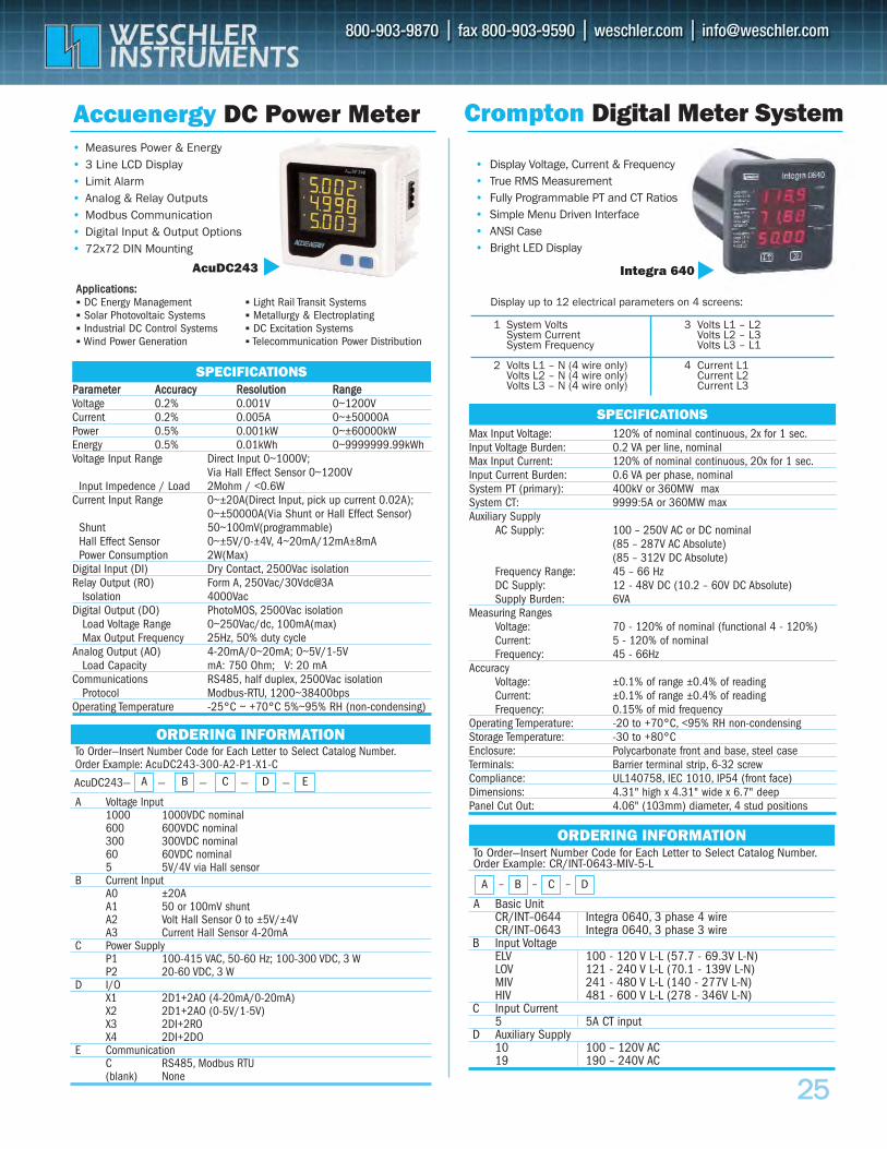
Accuenergy DC Power Meter• Measures Power & Energy• 3 Line LCD Display • Limit Alarm• Analog & Relay Outputs • Modbus Communication• Digital Input & Output Options • 72x72 DIN Mounting
AcuDC243
Crompton Digital Meter System
To Order—Insert Number Code for Each Letter to Select Catalog Number.Order Example: CR/INT-0643-MIV-5-L
A Basic UnitCR/INT–0644 Integra 0640, 3 phase 4 wireCR/INT–0643 Integra 0640, 3 phase 3 wire
B Input VoltageELV 100 - 120 V L-L (57.7 - 69.3V L-N)LOV 121 - 240 V L-L (70.1 - 139V L-N)MIV 241 - 480 V L-L (140 - 277V L-N)HIV 481 - 600 V L-L (278 - 346V L-N)
C Input Current5 5A CT input
D Auxiliary Supply10 100 – 120V AC19 190 – 240V AC
ORDERING INFORMATION
A – B – C – D
Max Input Voltage: 120% of nominal continuous, 2x for 1 sec.Input Voltage Burden: 0.2 VA per line, nominalMax Input Current: 120% of nominal continuous, 20x for 1 sec.Input Current Burden: 0.6 VA per phase, nominalSystem PT (primary): 400kV or 360MW maxSystem CT: 9999:5A or 360MW maxAuxiliary Supply
AC Supply: 100 – 250V AC or DC nominal(85 – 287V AC Absolute)(85 – 312V DC Absolute)
Frequency Range: 45 – 66 HzDC Supply: 12 - 48V DC (10.2 – 60V DC Absolute)Supply Burden: 6VA
Measuring RangesVoltage: 70 - 120% of nominal (functional 4 - 120%)Current: 5 - 120% of nominalFrequency: 45 - 66Hz
AccuracyVoltage: ±0.1% of range ±0.4% of readingCurrent: ±0.1% of range ±0.4% of readingFrequency: 0.15% of mid frequency
Operating Temperature: -20 to +70°C, <95% RH non-condensingStorage Temperature: -30 to +80°CEnclosure: Polycarbonate front and base, steel caseTerminals: Barrier terminal strip, 6-32 screwCompliance: UL140758, IEC 1010, IP54 (front face)Dimensions: 4.31" high x 4.31" wide x 6.7" deepPanel Cut Out: 4.06" (103mm) diameter, 4 stud positions
SPECIFICATIONS
PPaarraammeetteerr AAccccuurraaccyy RReessoolluuttiioonn RRaannggeeVoltage 0.2% 0.001V 0~1200VCurrent 0.2% 0.005A 0~±50000APower 0.5% 0.001kW 0~±60000kWEnergy 0.5% 0.01kWh 0~9999999.99kWhVoltage Input Range Direct Input 0~1000V;
Via Hall Effect Sensor 0~1200VInput Impedence / Load 2Mohm / <0.6W
Current Input Range 0~±20A(Direct Input, pick up current 0.02A);0~±50000A(Via Shunt or Hall Effect Sensor)
Shunt 50~100mV(programmable)Hall Effect Sensor 0~±5V/0-±4V, 4~20mA/12mA±8mAPower Consumption 2W(Max)
Digital Input (DI) Dry Contact, 2500Vac isolationRelay Output (RO) Form A, 250Vac/30Vdc@3A
Isolation 4000VacDigital Output (DO) PhotoMOS, 2500Vac isolation
Load Voltage Range 0~250Vac/dc, 100mA(max)Max Output Frequency 25Hz, 50% duty cycle
Analog Output (AO) 4-20mA/0~20mA; 0~5V/1-5VLoad Capacity mA: 750 Ohm; V: 20 mA
Communications RS485, half duplex, 2500Vac isolationProtocol Modbus-RTU, 1200~38400bps
Operating Temperature -25°C ~ +70°C 5%~95% RH (non-condensing)
SPECIFICATIONS
• Display Voltage, Current & Frequency• True RMS Measurement• Fully Programmable PT and CT Ratios• Simple Menu Driven Interface• ANSI Case• Bright LED Display
Integra 640
1 System VoltsSystem CurrentSystem Frequency
2 Volts L1 – N (4 wire only)Volts L2 – N (4 wire only)Volts L3 – N (4 wire only)
3 Volts L1 – L2Volts L2 – L3Volts L3 – L1
4 Current L1Current L2Current L3
Display up to 12 electrical parameters on 4 screens:
To Order—Insert Number Code for Each Letter to Select Catalog Number.Order Example: AcuDC243-300-A2-P1-X1-C
A Voltage Input1000 1000VDC nominal600 600VDC nominal300 300VDC nominal60 60VDC nominal5 5V/4V via Hall sensor
B Current InputA0 ±20A A1 50 or 100mV shuntA2 Volt Hall Sensor 0 to ±5V/±4VA3 Current Hall Sensor 4-20mA
C Power SupplyP1 100-415 VAC, 50-60 Hz; 100-300 VDC, 3 WP2 20-60 VDC, 3 W
D I/OX1 2D1+2AO (4-20mA/0-20mA)X2 2D1+2AO (0-5V/1-5V)X3 2DI+2ROX4 2DI+2DO
E CommunicationC RS485, Modbus RTU(blank) None
ORDERING INFORMATION
BA C D EAcuDC243— — — — —
AApppplliiccaattiioonnss:: DC Energy Management Solar Photovoltaic Systems Industrial DC Control Systems Wind Power Generation
Light Rail Transit Systems Metallurgy & Electroplating DC Excitation Systems Telecommunication Power Distribution

To Order—Insert Number Code for Each Letter to Select Catalog Number.Order Example: Acuvim-EL-D-60-5A-P1
A ModelII-D Acuvim II IIR-D Acuvim II with DataloggingAL-D Acuvim LBL-D Acuvim L with Energy Pulse & Alarm OutputsCL-D Acuvim L with RS485 Modbus Comm (half-duplex)EL-D Acuvim L with Time of Use & RS485 Modbus Comm
B Frequency50 50 Hz60 60 Hz
C Current Input5A 5 Amp1A 1 Amp
D Power SupplyP1 100-415 VAC, 50-60 Hz; 100-300 VDC, 3 WP2 20-60 VDC, 3 W
PPlluugg--IInn OOppttiioonnss ffoorr AAccuuvviimm IIII:: ((sseelleecctt uupp ttoo 33))DI Four Digital Input (wet) 20-220V AC/DC, 2mA max.RO Two Form A Relay Out 250VAC/30VDC, 5A res., 2A inductive DO Two Isolated Digital Out 0-250V AC/DC, 100mA, photo-MOS AO Two Analog Out specify 0-5V, 1-5V, 0-20mA, 4-20mA (15V max)AI Two Analog In specify 0-5V, 1-5V, 0-20mA, 4-20mANET Ethernet Communications 10/100M Modbus TCP/IP
ORDERING INFORMATION
BA C DAcuvim— — — —
2255aa
Accuenergy Power Meters• Revenue Grade Metering
• 5 Function Display
• Power Quality Analysis
• Over/Under Limit Alarm
• Data-Logging (Acuvim IIR)
• Web Server & Email Enabled
• Remote Switch Control
• Analog & Digital I/O Options
• 92x92 DIN or 4" ANSI RoundMounting
• Multifunction TRMS Meter
• 4 Quadrant Energy
• Power Quality Analysis
• Demand
• Over/Under Limit Alarm
• Wide Temperature Range
• RS485 Modbus Option
• 92x92 DIN or 4" ANSI Round Mounting Acuvim-L Acuvim II
COMMON SPECIFICATIONSSystem Configurations: 3LN/3CT, 3LN/2CT, 2LN/2CT*, 2LN/1CT*, 2LL/3CT,
2LL/2CT, 2LL/1CT*, 1Ø/3Line, 1Ø/2Line Voltage Input: 400 VAC L-N, 690 VAC L-L full scale, 45-65 Hz
Withstand: 1500 VAC continuous, 3250 VAC for 1 minuteInput Z: 2 Mohm per phase
Current Input: 1 or 5 A nominal, 0-6A metering rangeWithstand: 20 Arms continuous, 100A for 1 sec.Burden: 0.05 VA typical @ 5 Arms
Display: LCD with white backlightTemperature: -25 to 70 °C operating, <95% RH (non-condensing)Environment: Pollution degree 2Dimensions: 3.8" H x 3.8" W x 2.0" D (96x96x51mm)
*not on Acuvim IIR or Acuvim-EL
The Acuvim II is a high-end multifunction power meter for monitoring and con-trolling power distribution systems. Plug-in modules expand the I/O capabilities.Alarms can be set for up to 16 parameters, selected from the 51 available.RS485 Modbus communication is standard, Ethernet is optional. The Acuvim IIRhas 4M of onboard memory for datalogging in 3 assignable historical logs.
PPaarraammeetteerr AAccccuurraaccyy RReessoolluuttiioonn RRaannggeeAcuvim-L Acuvim-EL
Voltage 0.5% 0.5% 0.1V 20V~500kVCurrent 0.5% 0.5% 0.02% 0~50000ACurrent Demand 0.5% 0.5% 0.02% 0~50000APower 1.0% 0.5% 0.1% -4294MW~4294MWReactive Power 1.0% 0.5% 0.1% -4294MVar~4294MVarApparent Power 1.0% 0.5% 0.1% 0~4294MVAPower Demand 1.0% 0.5% 0.1% 0~4294MWReactive Power Demand 1.0% 0.5% 0.1% 0~4294MVarApparent Power Demand 1.0% 0.5% 0.1% 0~4294MVAPower Factor 1.0% 0.5% 0.1% -1.0~1.0Frequency 0.2% 0.2% 0.01Hz 45~65HzEnergy 1.0% 0.5% 0.1kWh 0~99999999.9kWhReactive Energy 1.0% 0.5% 0.1kvarh 0~99999999.9kVarhApparent Energy 1.0% 0.5% 0.1VAh 0~99999999.9kVAhHarmonics 2.0% -- 0.1% 0~100.0%Running Time 0.1h 0~9999999.9h
PPaarraammeetteerr AAccccuurraaccyy RReessoolluuttiioonn RRaannggeeAcuvim II Acuvim IIR
Voltage 0.2% 0.2% 0.1V 20V~500kVCurrent 0.2% 0.2% 0.001A 5mA~50000APower 0.5% 0.2% 1W -9999MW~9999MWReactive Power 0.5% 0.2% 1var -9999MVar~9999MvarApparent Power 0.5% 0.2% 1VA 0~9999MVAPower Demand 0.5% 0.2% 1W -9999MW~9999MWReactive Power Demand 0.5% 0.2% 1var -9999MVar~9999MvarApparent Power Demand 0.5% 0.2% 1VA 0~9999MVAPower Factor 0.5% 0.2% 0.001 -1.000~1.000Frequency 0.2% 0.2% 0.01Hz 45.00~65.00HzEnergy, Primary 0.5% 0.2% 0.1kWh 0-99999999.9kWhEnergy, Secondary 0.5% 0.2% 0.001kWh 0-999999.999kWhReactive Energy, Primary 0.5% 0.2% 0.1kvarh 0-99999999.9kvarhReactive Energy, Sec. 0.5% 0.2% 0.001kvarh 0-999999.999kvarhApparent Energy, Primary 0.5% 0.2% 0.1kVAh 0-99999999.9kVAhApparent Energy, Sec. 0.5% 0.2% 0.001kVAh 0-999999.999kVAhHarmonics 2.0% 2.0% 0.1% 0.0%~100.0%Phase Angle 2.0% 2.0% 0.1° 0.0°~359.9°Unbalance Factor 2.0% 2.0% 0.1% 0.0%~100.0%Running Time 0.01h 0~9999999.99h
MMeeaassuurreedd PPaarraammeetteerrss:: Voltage V1, V2, V3, V12, V23, V31 Current I1, I2, I3, In Power P1, P2, P3, Psum Reactive Power Q1, Q2, Q3, Qsum Apparent Power Ssum Frequency F Power Factor PF1, PF2, PF3, PF Energy Ep_imp, Ep_exp
Reactive Energy Eq_imp, Eq_exp Demand Dmd_I1, Dmd_I2,
Dmd_I3, Dmd_P, Dmd_qInput Harmonics 2nd-15th & THD (V & I) Unbalance (V & I) Max/Min (V & I) with time stamps Max Demand (I & P) Running Hours
MMeeaassuurreedd PPaarraammeetteerrss:: Phase Voltage V1, V2, V3, Vlnavg Line Voltage V12, V23, V31, Vllavg Current I1, I2, I3, In, Iavg Power P1, P2, P3, Psum Reactive Power Q1, Q2, Q3, Qsum Apparent Power S1, S2, S3, Ssum Frequency F Power Factor PF1, PF2, PF3, PF Energy Ep_imp, Ep_exp, Ep_total,
Ep_net Reactive Energy Eq_imp, Eq_exp,
Eq_total, Eq_net
Apparent Energy Es Demand Dmd_P, Dmd_Q, Dmd_S,
Dmd_I1, Dmd_I2, Dmd_I3 Harmonics 2nd-31st* & THD (V & I) Voltage Crest Factor THFF (TIF) Current K Factor Unbalance & Unbalance Factor (V & I) Max/Min Statistics with time stamps
for 28 parameters Running Hours and Real Time Clock*up to 63rd harmonic on Acuvim IIR
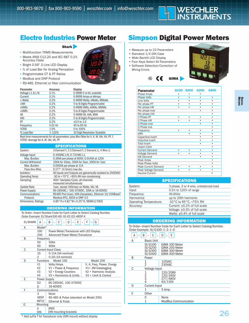
DIG
ITALM
ETERS
26
Electro Industries Power Meter
• Multifunction TRMS Measurements • Meets ANSI C12.20 and IEC 687 0.2%
Accuracy Class• Bright 0.56" 3 Line LED Display• % of Load Bar for Analog Perception• Programmable CT & PT Ratios• Modbus and DNP Protocol • RS-485, Ethernet or fiber communication
Shark
Parameter Accuracy DisplayVoltage L-L & L-N: 0.1% 0-9999 V or kV, scalableCurrent: 0.1% 0-9999 Amps or kAmps± Watts 0.2% 0-9999 Watts, kWatts, MWatts±Wh 0.2% 5 to 8 Digits Programmable±VARs 0.2% 0-9999 VARs, kVARs, MVARs±VARh 0.2% 5 to 8 Digits ProgrammableVA 0.2% 0-9999 VA, kVA, MVAVAh 0.2% 5 to 8 Digits ProgrammablePF 0.2% ±0.5 to 1.0 Frequency 0.01 Hz 45 to 65 Hz%THD 1.0% 0 to 100% % Load Bar 1-120% 10 Digit Resolution Scalable Real time measurements for all parameters; plus Min/Max for V, A, W, VAr, VA, PF, f, %THD: Average for A, W, VAr, VA, PF
System: 3 Element Y, 2.5 Element Y, 2 Element ∆, 4 Wire ∆ Voltage Input: 0-416VAC L-N, 0-721VAC L-L
Max. Burden: 0.36VA per phase at 600V, 0.014VA at 120V Current Withstand: 100A for 10sec, 300A for 3sec, 500A for 1sec
Max. Burden: 0.005VA per phase at 11A Pass-thru Wire: 0.177" (4.5mm) max dia.
Isolation: All Inputs and Outputs are galvanically isolated to 2500VAC Operating Temp: -30 to +70°C, <95% RH non-condensing Sampling: 400+ Samples/Cycle, all channels
measured simultaneously Update Rate: 1sec, except 100msec on Watts, VAr, VA Power Supply: 90-265VAC / 100-370VDC, 10VA or 18-60VDCCommunications: RS485 Port (rear), IrDA (faceplate), Ethernet 10/100BaseT
Protocol: Modbus RTU, ASCII or DNP 3.0 Dimensions, Ratings: 4.85"H x 4.82"W x 4.25"D, NEMA12 FACE
SPECIFICATIONS
ORDERING INFORMATIONTo Order—Insert Number Code for Each Letter to Select Catalog Number. Order Example: EI/Shark100-60-10-V2-D2-485P-X
A Model*100 Power Meter/Transducer with LED Display 200 Advanced Power Meter/Transducer
B Frequency50 50Hz 60 60Hz
C Current Input Class10 0-11A (5A nominal) 2 0-2A (1A nominal)
D Functions Model 100 Model 200V1 Volts/Amps V, A, Freq, Power, Energy V2 V1 + Power & Frequency V1+ 2M DataloggingV3 V2 + Energy Counters V2 + Harmonic AnalysisV4 V3 + Harmonics & Limits V3 + Limit & Control
E Power SupplyD2D
90-265VAC, 100-370VDC18-60VDC
RS-485 & Pulse (standard on Model 200)Ethernet & Pulse
F Communications
X ANSI DIN DIN mounting brackets
* Add suffix T for Transducer only (DIN mount) without display
A – B – C – D – E – FEI/SHARK
• Measure up to 23 Parameters• Standard 1/4 DIN Case• Wide Backlit LCD Display• Four Keys Select All Parameters• Software Detection/Correction of
Wiring Errors
PPaarraammeetteerr GG110000 GG220000 GG330000 GG440000Phase Amps • • •Phase Volts • • • •Line Volts • • • •Per phase PF • • • •Per phase kW • • • •Per phase kvar • •Per phase kVA •3 Phase PF • • • •3 Phase kW • • • •3 Phase kvar • •3 Phase kva •Frequency • • • •kWh • • •Capacitive kvarh • •Inductive kvarh • •Total kvarh • •Import kVah •Current Demand • • • •Voltage Demand • • • •kW Demand • •Peak Amps •Peak Phase Volts •Peak Current Demand • • • •Peak Voltage Demand • • • •Neutral Current •
System: 3 phase, 3 or 4 wire, unbalanced load Input 0.5% to 120% of range Frequency: 45-65Hz Harmonics: up to 20th harmonic Operating Temperature: -10°C to 65°C, <75% RH Accuracy: Current: ±0.2% of full scale
Voltage: ±0.3% of full scaleWatts: ±0.4% of full scale
SPECIFICATIONS
Simpson Digital Power Meters
GIMA
To Order—Insert Number Code for Each Letter to Select Catalog Number. Order Example: SI/G100–1–3–1–0
A Basic UnitSI/G100 GIMA 100 Meter SI/G200 GIMA 200 Meter SI/G300 GIMA 300 Meter SI/G400 GIMA 400 Meter
B Power1 115VAC 2 230VAC
C Voltage Input1 120/208V 2 120/240V 3 277/480V 4 63/110V
D Current Input1 5 Amp
E Other0 None1 ModBus Communication
ORDERING INFORMATION
A – B – C – D – E
G–
G Mounting
None 485PX
INP10
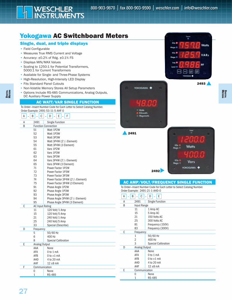
To Order—Insert Number Code for Each Letter to Select Catalog Number.Order Example: 2491-53-11-5-AHF-0
A 2491 Single FunctionB Function Connection
51 Watt 1P2W52 Watt 1P3W53 Watt 3P3W54 Watt 3P4W (21/2 Element)55 Watt 3P4W (3 Element)61 Vars 1P2W62 Vars 1P3W63 Vars 3P3W64 Vars 3P4W (21/2 Element)65 Vars 3P4W (3 Element)71 Power Factor 1P2W72 Power Factor 1P3W73 Power Factor 3P3W74 Power Factor 3P4W (21/2 Element)75 Power Factor 3P4W (3 Element)91 Phase Angle 1P2W92 Phase Angle 1P3W93 Phase Angle 3P3W94 Phase Angle 3P4W (21/2 Element)95 Phase Angle 3P4W (3 Element)
C AC Input Rating11 120 Volt/1 Amp15 120 Volt/5 Amp21 240 Volt/1 Amp25 240 Volt/5 Amp33 Special (Describe)
D Frequency5 50/60 Hz6 400 Hz8 Special Calibration
E Analog OutputAAA NoneAFA 0 to 1 mA AFB 0 to ±1 mA AHD 4 to 20 mAAHF 12 ±8 mA
F Communication0 None1 RS-485
To Order—Insert Number Code for Each Letter to Select Catalog Number. Order Example: 2491-21-1-AHD-0
A 2491 Single FunctionB Input Range
11 1 Amp AC15 5 Amp AC21 150 Volts AC25 300 Volts AC81 Frequency (150V)83 Frequency (300V)
C Frequency1 50/60 Hz2 400 Hz3 Special Calibration
D Analog OutputAAA NoneAFA 0 to 1 mAAFB 0 to ±1 mAAHD 4 to 20 mAAHF 12 ±8 mA
E Communication0 None1 RS-485
Yokogawa AC Switchboard Meters
• Field Configurable• Measures True RMS Current and Voltage• Accuracy: ±0.2% of Rdg. ±0.1% FS• Displays MIN/MAX Values• Scaling to 1250:1 for Potential Transformers,
5000:1 for Current Transformers• Available for Single- and Three-Phase Systems• High-Resolution, High-Intensity LED Display• Fits Standard Panel Cutouts• Non-Volatile Memory Stores All Setup Parameters• Options Include RS-485 Communications, Analog Outputs,
DC Auxiliary Power Supply
Single, dual, and triple displays
2493
2491
AC AMP/VOLT/FREQUENCY SINGLE FUNCTION
A – B – C – D – E
2492
AC WATT/VAR SINGLE FUNCTION
A – B – C – D – E – F
DIG
ITAL
MET
ERS
27
DIG
ITALM
ETERS
To Order—Insert Number Code for Each Letter to Select Catalog Number.Order Example: 2493-08-51-1-AHD-1-1
A 2493 Triple DisplayB Function/Connections
07 Volt/Amp/Hz 1P2W08 Volt/Amp/Hz 3P3W09 Volt/Amp/Hz 3P4W
C AC Volt/Amp Rating51 150V /1 A 55 150V /5 A 61 300V /1 A 65 300V /5 A 71 600V /1 A 75 600V /5 A
D Frequency1 50/60 Hz2 400 Hz
E Analog OutputAAA NoneAFA 0 to 1 mA DCAHD 4 to 20 mA DC
F Communication Protocol1 Yokogawa ASCII2 Modbus
G Auxiliary Power1 120/240 VAC3 24 VDC4 48 VDC5 125 VDC
AC VOLT/AMP/HERTZ
A – B – C – D – E – F – G
DIG
ITALM
ETERS
To Order—Insert Number Code for Each Letter to Select Catalog Number.Order Example: 2493-34-11-1-AFA-1-1
A 2492 Dual Display 2493 Triple DisplayB Function/Connection B Function/Connection
40 Watt/VAR 1P2W 34 Watt/VAR/PF 1P2W41 Watt/VAR 1P3W 35 Watt/VAR/PF 1P3W42 Watt/VAR 3P3W 36 Watt/VAR/PF 3P3W43 Watt/VAR 3P4W (2½ Element) 37 Watt/VAR/PF 3P4W (2½ Element)44 Watt/VAR 3P4W (3 Element) 38 Watt/VAR/PF 3P4W (3 Element)45 Watt/PF 1P2W46 Watt/PF 1P3W47 Watt/PF 3P3W48 Watt/PF 3P4W (2½ Element)49 Watt/PF 3P4W (3 Element)
C AC Input Rating C AC Input Rating12 120 Volt/1 Amp 11 120 Volt/1 Amp13 120 Volt/5 Amp 15 120 Volt/5 Amp16 240 Volt/1 Amp 21 240 Volt/1 Amp17 240 Volt/5 Amp 25 240 Volt/5 Amp
D Frequency D Frequency5 50/60 Hz 1 50/60Hz6 400 Hz 2 400Hz
E Analog Output E Analog OutputAAA None AAA NoneAFA 0 to 1 mA AFA 0 to 1 mAAHD 4 to 20 mA AHD 4 to 20 mA
F Communication F Communication Protocol0 None 1 Yokogawa ASCII1 RS-485 2 Modbus
G Aux. Power Supply G Aux. Power Supply1 120 Volt 50/60 Hz 1 120/240 VAC 2 240 Volt 50/60 Hz 3 24 VDC
4 48 VDC5 125 VDC
To Order—Insert Number Code for Each Letter to Select Catalog Number.Order Example: 2492-16-1-AHD-0-1
A 2492 Dual DisplayB Function Connection
12 150 Volt/1 Amp AC13 300 Volt/1 Amp AC16 150 Volt/5 Amp AC17 300 Volt/5 Amp AC22 150 Volt and 50/60 Hz23 300 Volt and 50/60 Hz26 150 Volt and 400 Hz27 300 Volt and 400 Hz
C Frequency (NA For Frequency Units)1 50/60 Hz2 400 Hz
D Analog OutputAAA NoneAFA 0 to 1 mAAHD 4 to 20 mA
E Communication0 None1 RS-485
F Auxiliary Power Supply1 120 Volt 50/60 Hz2 240 Volt 50/60 Hz
To Order—Insert Number Code for Each Letter to Select Catalog Number.Order Example: 2493-3-01-AFA-1-1
A 2493 Triple DisplayB Connections
1 3P3W Volts AC2 3P4W Volts AC5 3-Phase A, B, C Amps AC
C Input Rating01 1 A05 5 A10 150 V20 300 V30 600 V
D Frequency1 50/60 Hz2 400 Hz
E Analog OutputAAA NoneAFA 0 to 1 mA DCAHD 4 to 20 mA DC
F Communication Protocol1 Yokogawa ASCII1 Modbus
G Auxiliary Power1 120/240 VAC3 24 VDC4 48 VDC5 125 VDC
Yokogawa AC Switchboard MetersAC VOLT OR AMP
A – B – C – D – E – F – G
AC VOLT/AMP AND VOLT/FREQUENCY
A – B – C – D – E – F
AC WATT/VAR/POWER FACTOR
A – B – C – D – E – F – G
28
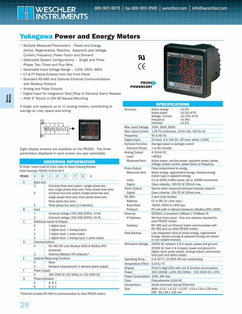
DIG
ITAL
MET
ERS
29
A single unit replaces up to 11 analog meters, contributing tosavings on cost, space and wiring.
Yokogawa Power and Energy Meters
To Order—Insert Code for Each Letter to Select Catalog Number. Order Example: PR300-42203-6A-0
A Basic Unit3 Universal three-wire system (single-phase two-
wire, single-phase three-wire, three-phase three wire)4 Universal four-wire system (single-phase two-wire,
single-phase three-wire, three-phase three-wire, three-phase four-wire)
5 Three-phase four-wire (2.5 element)B Input
1 Universal voltage (150/300/600V), 1A AC2 Universal voltage (150/300/600V), 5A AC
C Additional Inputs & Outputs0 1 digital input1 1 digital input, 1 analog output2 1 digital input, 1 pulse output3 1 digital input, 1 analog input, 1 pulse output
D Communications0 RS-485 (PC Link, Modbus ASCII & Modbus RTU
protocols)3 Ethernet (Modbus TCP protocol)*
E Optional Measuring Functions0 None3 Demand measurement (1 demand alarm output)
F Power Supply6 100-240V AC (50/60Hz) or 130-300V DC
G Phase Indication A A, B, CR R, S, T
SPECIFICATIONS
ORDERING INFORMATION
• Multiple Measured Parameters – Power and Energy (Active, Regenerative, Reactive, Apparent) plus Voltage,Current, Frequency, Power Factor and Demand
• Selectable System Configurations – Single and ThreePhase; Two, Three and Four Wire
• Selectable Input Voltage Range – 120V, 240V, 480V• CT & PT Ratios Entered from the Front Panel• Standard RS-485 and Optional Ethernet Communications
with Modbus Protocol• Analog and Pulse Outputs• Digital Input for Integration Start/Stop or Demand Alarm Release • ANSI 4" Round or DIN 96 Square Mounting
*Ethernet includes RS-485 for communication to other PR300 meters
Eight display screens are available on the PR300. The threeparameters displayed in each screen are user selectable.
BA C D E F GPR300 0
Accuracy: Active energy ±0.5%Active power ±0.5% of FSVoltage, Current ±0.25% of FSFrequency ±0.5HzDemand ±0.5%
Max. Input Voltage: 150V, 300V, 600VMax. Input Current: 1.2X FS continuous, 2X for 10s, 10X for 3sFrequency: 45 to 65 HzDigital Input: On level: 4.5-25V DC, Off level: within ±1VDCDemand Function: Average power or average current
Demand Period: 1 to 60 minutesAnalog Output: 4-20mA DC
Load: <600ΩMeasured Item: Active power, reactive power, apparent power, phase
voltage, phase current, power factor or frequencyPulse Output: Pulse proportional to energy
Measured Item: Active energy, regenerative energy, reactive energy (Lead/Lag) or apparent energy
Units: 0.1 to 5000.0 kWh/pulse; set in 100Wh incrementsSignal: Open collector, 30V DC @ 200mA max.
Alarm Output: Alarms when measured demand exceeds setpointSignal: Open collector, 30V DC @ 200mA max.
RS-485: 2-wire (half-duplex)Address: 01 to 99 (31 units max.)Buad Rate: 19200, 9600 & 2400 bpsProtocol: PC Link (with or without checksum), Modbus (RTU, ASCII)
Ethernet: IEEE802.3 compliant 10Base-T/100Base-TXIP Address: Set from front panel. Only one address required for
each PR300 cluster.Gateway: RS-485 port on Ethernet meter communicates with
RS-485 port on other PR300 meters Data Backup: Last integrated value of active energy, regenerative
energy, reactive energy & apparent energy are stored in non-volatile memory
Withstand Voltage: 2500V AC between V & A inputs, power and ground;2500V AC from V & A inputs, power and ground to digital input, pulse output, analog output, communica-tions port and alarm output
Operating Temp.: 0 to 50°C, 20-90% RH non-condensingTemperature Effect: 0.01%/°C Display: Three 5-digit LEDs with unit & function annunciatorsPower: 100-240VAC ±10% (50/60Hz) , 130-300V DC ±15% Power Consumption: 10VA, 5W max.Case: Polycarbonate UL94-V0Connections: Screw terminals (except Ethernet)Size: ANSI: 4.33" x 4.33" x 5.05" (110 x 110 x 128 mm)
DIN: 96 x 96 x 126 mm
PR300POWERCERT
- - -

49
To Order—Insert Number Code for Each Letter to Select Catalog Number. Order Example: DMMS-300-R-2E-X-KV-KA-MW-120-115A-MODR-X
A Basic UnitDMMS-300 Multi-Function Power Monitor DMMS-350 Multi-Function Power Monitor DMMS-425 Multi-Function Power Monitor
B Reading Type (N/A for DMMS-425)X KVAH Reading R KVARH Reading
C Connection3E 3 Element–3-Phase 4-Wire Wye (3 PTs)2.5E 2.5 Element–3-Phase 4-Wire Wye (2 PTs) 2E 2 Element–3-Phase 3-Wire Delta
D Harmonic Capability (N/A for DMMS-425)X None H Harmonics to 31st Order
E Volts LabelV Volts Label KV Kilovolts Label
F Amps LabelA Amps Label KA Kiloamps Label
G Power LabelKW Kilowatts Label MW Megawatts Label
H Operation Monitoring Voltage120 120/208V (Direct Reading or PTs) G 277/480 (Direct Reading)
I Operating Power115A 115 VAC ±20%, 6 VA 230A 230 VAC ±20%, 6 VA D 24–48 VDC ±20%, 6 VA D2 125 VAC or DC ±20%, 6 VA Universal D4 12 VDC ±20%, 6 VA
J COM ProtocolMODR ModBus RTU MODA ModBus ASCII DNP DNP 3.0 EI EI-Bus
K Relay OptionsX None NL 2 Relays–1 KYZ Pulse (DMMS-300 only) NL2 3 KYZ Pulses
L Output Module OptionSF485DB RS485 Output (Digital)SF532DB RS232 Output (Digital)SHNI-1 10 Channel 0-1mA (DMMS 300 only) SHNI-20 10 Channel 4-20mA (DMMS 300 only)
Electro Industries Multi-Function Power Monitor• Built-in Ethernet Connectivity (DMMS-350)• ANSI Footprint• True RMS .2% Accuracy (DMMS-300)• .3% Accuracy (DMMS-425)• Harmonic Distortion to 31st Order• Harmonic Waveform Capture (DMMS-300)• MIN/MAX Demand• 10 Channels of Analog Transducer Output• ModBus, DNP 3.0• Utility Grade
Accuracy DMMS-300 DMMS-350 DMMS-425Volts: 0.2% of Full Scale 0.2% 0.3%Amperes: 0.2% of Full Scale 0.2% 0.3%KW: 0.4% of Full Scale 0.4% 0.6%KVA: 0.4% of Full Scale 0.4% 0.6%KVAR: 0.4% of Full Scale 0.4% 0.6%PF: 1.0% of Full Scale 0.4% 0.6%KW Hour: 0.4% of Full Scale 0.4% 0.6%KVA Hour: 0.4% of Full Scale 0.4% 0.6%KVAR Hour: 0.4% of Full Scale 0.4% 0.6%Frequency: 0.02 Hz 0.02 Hz 0.02 HzHarmonics: 0.50% 0.50% NA Input Voltage: 150V phase to neutral, 300V phase to phase–std.
300V phase to neutral, 600V phase to phase–G option 300V phase to neutral, 150V phase to phase–75 option
Input Current: 5A at Full Scale, 10A maximum Burden: Voltage 0.1 VA maximum; Current 0.1 VA maximum Operating Temp.:-20°C to +70°C Sensing Method:True RMS sampling at 64 samples per cycle
SPECIFICATIONS
ORDERING INFORMATION
A – B – C – D – E – F – G – H – I – J – K – L
DMMS-300
DMMS-425
The DMMS-300 is a four-quadrant multi-function power meter that measures:
It replaces individual single-function meters by providing three parameter displays and an easy to use front panel interface, as well as digital and analog connections to a control or monitoring system. The DMMS-300 includes advanced power measurements and min/max storage for power analysis & control. User-defined setpoints are available for most measured values.
The DMMS-350 adds a standard Ethernet TCP/IP connection. The meter is ideal for applications requiring real time metering or data streaming to a LAN or through the Internet. Information is reported using the industry standard Modbus TCP/IP protocol. Harmonic measurements are also standard in the DMMS-350.
The DMMS-425 is an economical power monitor that measures and calculates over 80 electrical parameters, including maximum and minimum values for every reading. This full four-quadrant meter has separate positive and negative Watthour counters and complies with ANSI C12 revenue metering accuracy requirements.
• 3Ø Voltage (L-N, L-L)• 3Ø Current• Neutral Current• Bi-directional KW
(3Ø & Total)
• Bi-directional KVAR (3Ø & Total)
• KVA (3Ø & Total)• PF (3Ø & Total)• Bi-directional KWh
• KVAh• Frequency• %THD• K Factor
29a

51
Electro Industries Utility Billing Meter• 0.6% W/Hr Revenue Meter• 20 Year Time of Use• Loss Compensation• Power Quality• Data Logging & Event Recording• Multiple Communication Paths• Modbus, DNP3, Ethernet, Web• Graphical LCD Display
• Normal Mode, Time of Use Mode, Diagnostic Mode
• Two Historic Logs, Multiple Demand Windows
• CBEMA/ITIC Log (Model 1270)• Setup Parameters Stored in
Non-Volatile Memory• Dial Out on Alarm or Event
To Order–Insert Number Code for Each Letter to Select Catalog Number.
A Model1260 Nexus Utility Billing Meter 1270 Nexus Utility Billing Meter with
Advanced Power Quality B Memory
S Standard A Advanced
C Form9S 120-277V L-N; 3E, 4W, Wye 35S 120-480V L-N; 2E, 3W, Delta 36S 120-277V L-N; 2 1/2 E, 4W, Wye SWB 120-277V L-N; programmable
D Class (Amps)02 Class 2 (0 to 2 A )020 Class 20 (0 to 20 A)
E Frequency60HZ 50HZ
F Power SupplyS Standard SE Std External DE 18-60V DC LV 69V AC ±20%
G Internal I/OX None INP2 Dial out Modem INP10 10Mb Ethernet INP100 10/100 Base T 4IPO 4 Pulse Output Relays
ORDERING INFORMATION
A – B – C – D – E – F – G
SPECIFICATIONSAccuracy:
Voltage 0.02%Current 0.05% Frequency 0.001Hz kWh @1.0PF 0.06% kWh @0.5PF 0.1% kVAR 0.1%kVA 0.1%PF 0.1%
Sensing: 16 bit A/D inputsTrue RMS measurements 8 channel sample & hold
Digital Inputs: 8 channels, self excited, dry contact Solid State Outputs (KYZ): 4 channels, form C, 350VDC/120mA Timing: Internal clock accurate to 1 min/month
IRIG-B input for sync to external GPS signal Standard Communications: IR port
Two RS-485 serial ports Modbus RTU, Modus ASCII, DNP3.0 protocols Data Speeds to 115kbps Eight high speed input channels
Optional Communications: Internal modems with data bufferingInternal Ethernet with multiple socket support & Modbus TCP/IP
Operating Temperature: -40°C to 85°C Security: Hardware & Password Locks Standard Power (S): 96-550VAC 50/60Hz auto-ranging meter
power from any of the 3 phases. External Power (SE): 96-275VAC 50/60Hz or
125VDC ±20%Dimensions: S case 6.96" dia x 6.0"deep
SWB case 6.813"W x 9.188"H x 9.30"DMemory: Model Log1 Log2 CBEMA Event Waveform Output Input 1260S 80 days 32 days 1024 512 5121260A 691 days 132 days 1024 512 5121270S 97 days 132 days 1024 1024 64 512 5121270A 602 days 132 days 1024 1024 96 512 512
External Modules EI/1MAON4 4 Channel Analog Outputs, 0-1mA EI/20MAON4 4 Channel Analog Outputs, 4-20mA EI/1MAON8 8 Channel Analog Outputs, 0-1mA EI20MAON8 8 Channel Anaolgo Output, 4-20mA EI/8AI1 8 Channel Analog Input, 0-1mA EI/8AI2 8 Channel Analog Input, 4-20mA EI/8AI3 8 Channel Analog Input, 0-5VDC EI/8AI4 8 Channel Analog Input, 0-1VDC 4RO1 4 Relay Outputs 4PO1 4 Solid State Pulse Outputs 8DI1 8 Digital Status Inputs MBIO I/O Module Mounting Brackets PSIO Additional I/O Power Supply Software NXDS1.0C Single User Dial-in Server License AIREPORTS1 AIREPORTS Single User License
EXTERNAL OPTIONAL MODULES
NEXUS 1270
29b
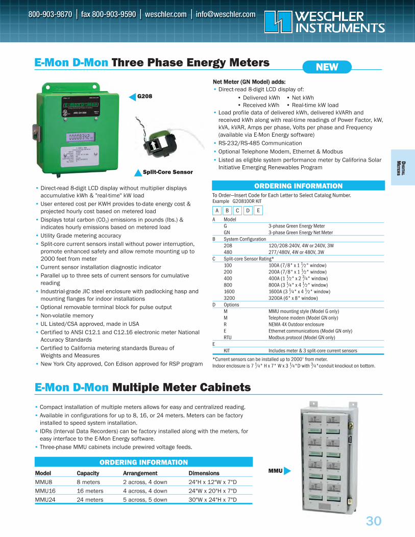
DIG
ITALM
ETERS
30
E-Mon D-Mon Three Phase Energy Meters
MMooddeell CCaappaacciittyy AArrrraannggeemmeenntt DDiimmeennssiioonnss
MMU8 8 meters 2 across, 4 down 24"H x 12"W x 7"D
MMU16 16 meters 4 across, 4 down 24"W x 20"H x 7"D
MMU24 24 meters 5 across, 5 down 30"W x 24"H x 7"D
G208
NNeett MMeetteerr ((GGNN MMooddeell)) aaddddss::• Direct-read 8-digit LCD display of:
• Delivered kWh • Net kWh• Received kWh • Real-time kW load
• Load profile data of delivered kWh, delivered kVARh and received kWh along with real-time readings of Power Factor, kW, kVA, kVAR, Amps per phase, Volts per phase and Frequency (available via E-Mon Energy software)
• RS-232/RS-485 Communication• Optional Telephone Modem, Ethernet & Modbus • Listed as eligible system performance meter by Califorina Solar
Initiative Emerging Renewables Program
• Direct-read 8-digit LCD display without multiplier displays accumulative kWh & "real-time" kW load
• User entered cost per KWH provides to-date energy cost & projected hourly cost based on metered load
• Displays total carbon (CO2) emissions in pounds (lbs.) & indicates hourly emissions based on metered load
• Utility Grade metering accuracy• Split-core current sensors install without power interruption,
promote enhanced safety and allow remote mounting up to 2000 feet from meter
• Current sensor installation diagnostic indicator• Parallel up to three sets of current sensors for cumulative
reading• Industrial-grade JIC steel enclosure with padlocking hasp and
mounting flanges for indoor installations• Optional removable terminal block for pulse output• Non-volatile memory• UL Listed/CSA approved, made in USA• Certified to ANSI C12.1 and C12.16 electronic meter National
Accuracy Standards• Certified to California metering standards Bureau of
Weights and Measures• New York City approved, Con Edison approved for RSP program
To Order—Insert Code for Each Letter to Select Catalog Number. Example G208100R KIT
A ModelG 3-phase Green Energy Meter GN 3-phase Green Energy Net Meter
B System Configuration208 120/208-240V, 4W or 240V, 3W 480 277/480V, 4W or 480V, 3W
C Split-core Sensor Rating* 100 100A (7/8" x 1 1/2" window) 200 200A (7/8" x 1 1/2" window)400 400A (1 1/2" x 2 3/4" window)800 800A (3 1/4" x 4 1/2" window)1600 1600A (3 1/4" x 4 1/2" window) 3200 3200A (6" x 8" window)
D OptionsM MMU mounting style (Model G only)M Telephone modem (Model GN only)R NEMA 4X Outdoor enclosure E Ethernet communications (Model GN only) RTU Modbus protocol (Model GN only)
EKIT Includes meter & 3 split-core current sensors
*Current sensors can be installed up to 2000' from meter. Indoor enclosure is 7 1/4" H x 7" W x 3 1/4"D with 3/4"conduit knockout on bottom.
ORDERING INFORMATION
E-Mon D-Mon Multiple Meter Cabinets
• Compact installation of multiple meters allows for easy and centralized reading.• Available in configurations for up to 8, 16, or 24 meters. Meters can be factory
installed to speed system installation. • IDRs (Interval Data Recorders) can be factory installed along with the meters, for
easy interface to the E-Mon Energy software.• Three-phase MMU cabinets include prewired voltage feeds.
MMUORDERING INFORMATION
Split-Core Sensor
A B C D E
NEW

D IG
ITAL
M
ETER
S
31
2120100WT KIT 120V, 1-Phase, 2W meter with one 100A split-core sensor 2120200WT KIT 120V, 1-Phase, 2W meter with one 200A split-core sensor 3208100WT KIT 120/208-240V, 1- or 2-Phase, 3W meter with two 100A split-core sensors 3208200WT KIT 120/208-240V, 1- or 2-Phase, 3W meter with two 200A split-core sensors
E-Mon D-Mon Wireless Energy Meters
To Order—Insert Code for Each Letter to Select Catalog Number. Example: 208100RWT KIT
A System208 120/208-240V, 4W or 240V, 3W 480 277/480V, 4W or 480V, 3W
B Split-core Sensor Rating 100 100A (7/8" x 11/2" window) 200 200A (7/8" x 11/2" window)400 400A (11/2" x 23/4" window)800 800A (31/4" x 41/2" window) 1600 1600A (31/4" x 41/2" window) 3200 3200A (6" x 8" window)
C ModelRWT Three phase Wireless
Energy Meter D Options (omit if no options)
D DemandE
KIT Includes meter & 3 split-core current sensors
• Direct-read 8-digit LCD displays kW load & accumulative kWh.
• Demand option displays kW Demand & kW Peak date and time (15 min interval stan-dard, 30 min available).
• Certified to ANSI C12.1 & C12.16 for Utility Grade Metering Accuracy (±1% from 1-100% of rated load).
• Built-in wireless transceiver is FCC certified not to interfere with existing infrastructure.
• Operates in the 915 MHz frequency-hopping, spread-spectrum license-free band.
ORDERING INFORMATION
Class 4100 Single Phase Meters
• Easy-to-read 6-digit electro-mechanical display for diagnostics.• Interfaces with E-Mon wireless gateways & software to automatically
compile data.• Can be mounted inside buildings within ~500 feet line-of-sight from each other
(up to 200 feet through walls)• Revenue grade accuracy meets ANSI C12.1 and C12.16.• On-board data memory. • Split-core current sensors allow for safe installation up to 2,000 feet from meter. • Non-metallic enclosure is ideal for installation inside commercial and
residential spaces.• Built-in wireless transceiver is FCC certified not to interfere with existing
infrastructure.• Wireless mesh network operates in the 915 MHz license-free band. • Self-configuring network allows for easy installation - no network
management required.
WGATEWAY Wireless Gateway WRSOFT Wireless Meter Reading Software
ORDERING INFORMATION ACCESSORIES
WT
Dimensions: 7" H x 6" W x 2" D Split-core current sensors have 7/8" x 11/2" window
A B C D E
Class 2100 Three Phase Meters
RWT
All E-Mon products are Made in USA.
Dimensions: 71/2" H x 71/2" W x 4" D
NEW
UL Listed. New York City approved. Con Edison approved for RSP program. Measurement Canada approved for revenue metering. California Bureau of Weights and Measures certified. Made in USA.
• Interfaces with E-Mon wireless gateways & software for in-building remote data collection.
• Self-configuring wireless mesh network installs easily, without network management.
• NEMA 4X outdoor enclosure has 3/4" conduit knockout on bottom. • Non-volatile Memory retains data during power interruption.• Meters can be mounted inside building (range ~500 feet line-of-sight,
up to 200 feet through walls).• Split-core current sensors install without power interruption, up to
2000 feet from meter. • Current sensor diagnostics assist in installation
~
~

DIG
ITALM
ETERS
32
E-Mon Energy software allows users to read and monitor energy con-sumption easily and effectively via on-site or off-site non-dedicated computers. Requires E-Mon meter with RS-485 or wireless interface.
• Windows 2000, XP & Vista compatible• Graphic profiling provides analytical charts and graphs with demand
profiling for 5-, 15-, 30- or 60-minute sampling rates • Generate and print itemized electric bills (using coincidental peak
demand date and time). Software will generate bills from user-specific time periods via profile data
• Reads up to 8 time periods, 4 seasons and multiple holidays for time-of-use (TOU) monitoring
• Reads E-Mon D-Mon meters, either on-site or off-site, via modem (cellular or telephone), Ethernet or a directly connected computer
• Exports data to spreadsheets for analysis (.csv files)• Exports data to MV-90 system (.hhf files)• Optional modem allows meters to be read anywhere in the world
where telephone or cellular service is available.• Wireless metering option allows users to remotely read Class 2100
& Class 4100 E-Mon D-Mon meters via Internet, Ethernet or tele-phone communication.
EMONENERGYSW Energy Monitoring Software* WRSOFT Wireless Option for Software IDR-8 1-8 Meter IDR** IDR-16 1-16 Meter IDR** RS232K E-Mon Energy Key USBK USB Key EKM-T Telephone Key/Modem EKM-E Ethernet Key/Modem
*Software packages include RS-232K Key (RS-485 to RS-232 converter) ** Available with optional two-screw removable terminal blocks. Add suffix “ST” to the end of the model number. (i.e. IDR-8-ST)
• Direct-read kW & kWh (no multiplier)• 8 digit LCD readout• Revenue-grade accuracy: ±1% from 1-100% of rated load • Retains readings during power failure• Split-core sensors for safe & easy installation up to 2000 feet
from meter• Parallel up to three (3) sets of current sensors for cumulative reading.
• Industrial grade JIC steel enclosure for indoor installations with 3/4"conduit knockout on bottom
• UL/CUL Listed, made in USA• New York City approved, Con Edison approved for RSP
program, Listed by the California Energy Commission
To Order—Insert Number Code for Each Letter to Select Catalog Number. Example 2120100-SA KIT
A System 2120 120V, 2-Wire (1 sensor) 3208 120/208-240V 3-Wire (2 sensors) 2277 277V, 2-Wire (4 digit display, 1 sensor)
B Split-core Sensor Rating 25 25A 50 50A 100 100A 200 200A
C Model-SA Class 1000 Single phase KWH Meter
D Options (not available on 277V systems)M MMU mounting style R NEMA 4X outdoor enclosure
EKIT Includes meter & split-core current sensor(s)
ORDERING INFORMATION
E-Mon D-Mon Single Phase KWH Meters
A B C D E
E-Mon D-Mon ENERGY™ Software
ORDERING INFORMATION
Dimensions: 6 3/4" H x 5 3/16" W x 31/4" D Split-core current sensors have 7/8" x 11/2" window
Class 1000
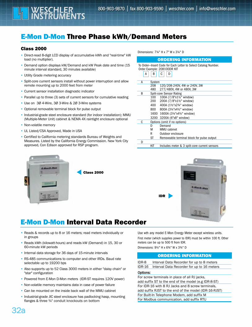
3322aa
To Order—Insert Code for Each Letter to Select Catalog Number.Order Example: 208100DR KIT
A System 208 120/208-240V, 4W or 240V, 3W480 277/480V, 4W or 480V, 3W
B Split-core Sensor Rating100 100A (7/8"x1½" window) 200 200A (7/8"x1½" window)400 400A (1½"x2¾" window)800 800A (3¼"x4½" window)1600 1600A (3¼"x4½" window)3200 3200A (6"x8" window)
C Options (omit if no options)D DemandM MMU cabinetR Outdoor enclosureST Removeable terminal block for pulse output
DKIT Includes meter & 3 split-core current sensors
E-Mon D-Mon Three Phase kWh/Demand Meters
E-Mon D-Mon Interval Data Recorder
• Direct-read 8-digit LCD display of accumulative kWh and "real-time" kWload (no multiplier).
• Demand option displays kW/Demand and kW Peak date and time (15 minute interval standard, 30 minutes available)
• Utility Grade metering accuracy
• Split-core current sensors install without power interruption and allow remote mounting up to 2000 feet from meter
• Current sensor installation diagnostic indicator
• Parallel up to three (3) sets of current sensors for cumulative reading
• Use on 3Ø 4-Wire, 3Ø 3-Wire & 2Ø 3-Wire systems
• Optional removable terminal block for pulse output
• Industrial-grade steel enclosure standard (for indoor installation); MMU(Multiple-Meter Unit) cabinet & NEMA 4X raintight enclosure optional
• Non-volatile memory
• UL Listed/CSA Approved, Made in USA
• Certified to California metering standards Bureau of Weights and Measures. Listed by the California Energy Commission. New York City approved, Con Edison approved for RSP program.
• Reads & records up to 8 or 16 meters; read meters individually or in groups
• Reads kWh (kilowatt-hours) and reads kW (Demand) in 15, 30 or 60-minute kW periods
• Internal data storage for 36 days of 15-minute intervals
• RS-485 communications to computer and other IRDs. Baud rate selectable up to 19200 bps
• Also supports up to 52 Class 3000 meters in either "daisy chain" or "star" configuration
• Powered from E-Mon D-Mon meters (IDR-ST requires 120V power)
• Non-volatile memory maintains data in case of power failure
• Can be mounted on the inside back wall of the MMU cabinet
• Industrial-grade JIC steel enclosure has padlocking hasp, mounting flanges & three ¾" conduit knockouts on bottom
ORDERING INFORMATION
ORDERING INFORMATION
BA C D
Class 2000
IDR
IDR-8 Interval Data Recorder for up to 8 metersIDR-16 Interval Data Recorder for up to 16 meters
OOppttiioonnss::For screw terminals in place of all RJ jacks,add suffix ST to the end of the model (e.g IDR-8-ST)For IDR-16 with 8 RJ Jacks and 8 screw terminals,add suffix RJST to the end of the model (IDR-16-RJST)For Built-In Telephone Modem, add suffix M For Modbus communication, add suffix RTU
Use wth any model E-Mon Energy Meter except wireless units.First meter (which supplies power to IDR) must be within 100 ft. Othermeters can be up to 500 ft from IDR.
Dimensions: 9½" H x 6¾" W x 3¾" D
Dimensions: 7¼" H x 7" W x 3¼" DClass 2000
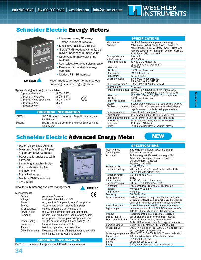
AN
ALOG
METER
S
Schneider Electric Energy Meters• Measures power, PF, energy
- active, apparent, reactive• Single row, backlit LCD display• 4 digit TRMS readout with units dis-
played under each numeric value • Direct read primary values - no
multiplier• User selectable default display page • Permanent & resettable energy
counters • Modbus RS-485 interface
• Use on 3φ LV & MV systems• Measures, V, A, Freq, PF, plus
4 quadrant power & energy• Power quality analysis to 15th
harmonic• Large, bright graphic display • Predicts demand for load
management• Digital kWh output • Modbus RS-485 interface• 1/4DIN size
EM1250
Measurement: True RMS, two quadrant power and energyAccuracy: Active power (kW) & energy (kWh) – class 0.5;
Apparent power (kVA) & energy (kVAh) – class 0.5;Reactive power (kVAR) & energy (kVARh) – class 1.0;Power Factor (PF) – class 0.5;
Data update rate: 1 secondVoltage inputs: V1, V2, V3, Vn
Measured voltage: 80-480 V L-L without PTsUp to 999 kV with external PTs
Overload: 600 V L-LBurden: 0.2 VA per phase max.Impedance: 3MΩ L-L and L-NFrequency: 50/60 Hz ±5%
CT primary rating: 5 A to 99.0 kA for EM1250,1 A to 99.0 kA for EM1251
CT secondary rating: 5 A for EM1250, 1 A for EM1251Current inputs: A1, A2, A3
Measurement range: 250 mA - 6 A (starting at 5 mA) for EM1250150 mA - 1.2 A (starting at 1 mA) for EM1251
Overload: 10 A (EM1250) or 2 A (EM1251), continuousBurden: 0.2 VA per phase max.Input resistance: < 0.1 ohm
Display: 3 parameter, 4 digit LCD with auto-scaling (k, M, G) Displayed parameters: Auto-scrolling with user selectable default display
page & password protected setup parametersCommunications: 2-wire RS-485, Modbus RTUPower supply: 44-277 VAC, 50/60 Hz; 44-277 VDC, 4 VAOperating temperature: -10 to +60°C, 5-95% RH non-condensingDimensions: 96mm x 96mm bezel, 83mm behind panelProtection: IP51 front, IP40 backRating: CATIII, protection class 2, pollution class 2
ORDERING INFORMATION
ORDERING INFORMATION
SPECIFICATIONS
SPECIFICATIONS
EM1250 EM1250 class 0.5 accuracy, 5 Amp CT Secondary andRS 485 port
EM1251 EM1251 class 0.5 accuracy, 1 Amp CT Secondary andRS 485 port
PM5110 Advanced Energy Meter with RS-485 communications
Ideal for sub-metering and cost management.
SSyysstteemm CCoonnffiigguurraattiioonnss (User selectable) 3 phase, 4-wire Y 3 CTs, 3 PTs3 phase, 3-wire delta 2 CTs, 3 PTs3 phase, 3-wire open delta 2 CTs, 2 PTs1 phase, 3-wire 2 CTs1 phase, 2-wire 1 CT
MMeeaassuurreemmeennttssCurrent: per phase & neutralVoltage: total, per phase L-L and L-NPower : real, reactive & apparent; total & per phaseEnergy: accumulated active, reactive & apparent% Unbalance: current, voltage L-L and voltage L-NPower Factor: true & displacement, total and per phaseDemand: present, last, predicted & peak for avg current,
active power, reactive power & apparent powerPower Quality: THD for current, voltage L-L and voltage L-NHarmonics: Individual harmonics to 15thTimers: I/O time, operating time, load timeOther Parameters: Frequency, min/max of instantaneous values with
time stamp, alarms with time stamp
Schneider Electric Advanced Energy Meter NEW
Measurement: True RMS, four quadrant power and energySampling rate: 64 samples per cycleAccuracy: Active energy ±0.5%; reactive energy ±2%;
Active power & apparent power – class 0.5; Current, Voltage - class 0.5Frequency – ±0.05%
Voltage inputs: V1, V2, V3, VnMeasured voltage: 20 to 400 V L-N / 35 to 690 V L-L without PTs
Up to 1 MV with external PTsAbsolute range: 35 V L-L to 760 V L-LImpedance: 5MΩ
Current inputs: A1, A2, A3; 1 A or 5 A nominalMeasured amps: 50 mA - 8.5 A (starting at 5 mA) Withstand: 10 A continuous, 10s/hr 50A, 1s/hr 500ABurden: <0.0262 VA at 8.5 AImpedance: < 0.3 mΩ
Frequency: 50/60 Hz ±5%Demand calculation: Rolling, fixed and rolling block, thermal methods
w/settable interval; can be synchronized to clock or command. Peak demand time stamped & stored
Alarm time stamp: 1s resolution, data stored in non-volatile memory Digital output: one scalable from 1 to 9,999,999 pulses per kWh;
40 VDC, 20 mA, 25 Hz max, 50% duty cycle Display: Backlit monochrome graphic LCD, 128x128 Display modes: Vector, graphical or 6 line numerical readoutFront panel indicators: Green LED for heartbeat/communication;
Amber LED for active alarm & energy pulse output Communications: 2-wire RS-485, Modbus RTU, Modbus ASCIIPower supply: 100-277 VAC L-N or 415V ±5% L-L, 45-65 Hz, <11
VA; 125-250 VDC ±20%, <4WOperating temperature: -25 to +70°C, 5-95% RH @50°C non-condensingDimensions: 96mm x 96mm bezel, 77mm behind panelProtection: IP52 front, IP30 backSafety: cULus per UL61010-1, CERating: CATIII, protection class 2, pollution class 2
PM5110
34
Recommended for load monitoring, loadbalancing, sub-metering & gensets.

AN
ALOG
METER
S
34a
Hoyt Multi-Function Digital Meters
Schneider Electric Multi-Function Digital Meter
• Displays multiple parameters- DC Volts & DC Amps- AC Volts, AC Amps, Frequency
• High visibility LED display• Surface or window mounting • Matches panel cutout of
Yokogawa 260 & Modutec 3S• Made in the USA
• Measure V, A, Freq, PF, Phaseangle, Unbalance, RPM
• Use on 3φ & 1φ systems• Large, bright LED display • Modbus RS-485 interface• Quick front panel setup• Selectable CT & PT ratios• Analog load bar• 1/4DIN size
D-CK920
DC
AC
AACC MMooddeellss:: TRMS SensingAC Volts Accuracy: 1% of reading ±1 count between
45 Hz and 65 HzResolution: 1 VoltRange: 0-285 VAC RMS
AC Amps Accuracy: 2% of reading ± 1 countResolution: 0.1 Amp to 99.9 A; 1 Amp from 100 to 999Range: 999 Amps RMS using CT’s with a maximum
secondary of 100ma.Frequency Accuracy: 0.5% from 45-65 Hz ±1 countCrest Factor: 3:1DDCC MMooddeellss::DC Volts Accuracy: 0.1% of reading ±1 count
Resolution: 0.1 Volts to 99.9 VDC; 1 Volt from 100 to 999Range: Max. direct input is 100 VDC. Use an external
divider to extend the range DC Amps Accuracy: 1% of reading ±1 count (excluding shunt errors)
Resolution: 0.1 Amp to 99.9 Amps; 1 Amp from 100 to 200Range: 200 Amps (requires external shunt)
AAllll MMooddeellss::Display: 0.38" LED, High IntensityCommon Mode Rejection: 86dB TypicalCommon Mode Range: ±2 VoltsOvervoltage Protection: 1.5 times max input for 1 minuteOperating Temperature: -20°C to +60°C, 0-95% RH non-condensingDimensions: 2.98" W x 2.25" H Panel Cutout: 2.90" x 1.26" for window mounting* Overall accuracy of this measurement is predicated on the accuracy ofthe shunt & length of connecting leads between the shunt and the D-CK920.Drift in the least significant digit may occur due to thermal changes in shuntor the operating environment.
Measurement: TRMS up to 9th harmonic,20 samples per cycle at 50Hz
Accuracy: 1.0% of reading (ACV, ACA, PF)*0.1% of reading (Freq)2 degrees (Phase angle)
Data update rate: 1 secondVoltage inputs: V1, V2, V3, Vn
Measured voltage: 80-480 V L-L without PTsUp to 999 kV with external PTs
Overload: 1.1 Un (480 V L-L continuous)Burden: 0.2 VA per phase max.Frequency: 45-65 Hz
Current CT inputs: 1A to 99.0 kA primary, 1 A to 5 A secondaryMeasured current: 50 mA - 6 A (starting at 5mA)Overload: 10 A continuousBurden: 0.2 VA per phase max.Input resistance: < 0.1 ohm
Display: 3 line, 4 digit LED with auto-scaling (k, M, G).Displayed parameters: Auto-scrolling with user selectable default display
page & password protected setup parameters.Analog load bar: 12 segment color coded LEDs Communications: 2-wire RS-485, up to 19200 baud, Modbus RTUPower supply: 44-277 VAC, 50/60 Hz; 44-277 VDC, 3 VAOperating temperature: -10 to +60°C, 5-95% RH non-condensingDimensions: 96mm x 96mm bezel, 83mm behind panelProtection: IP51 front, IP40 backRating: CATIII, protection class 2, pollution class 2
* 0.05% of full scale additional error for input current below 100mA
ORDERING INFORMATION
ORDERING INFORMATION
SPECIFICATIONS
SPECIFICATIONS
DM6200
D-CK920-VADC 99.9ADC, 99.9VDC (STD) D-CK920-VADC-1 200ADC, 99.9VDCD-CK920-VADC-2 1000ADC, 200VDCD-CK920-VADC-3 5.0ADC, 99.9VDCD-CK920-VADC-4 4V@400ADC, 99.9VDC (SPECIAL)D-CK920-VADC-5 99.9ADC, 99.9VDCD-CK920-VADC-6 500ADC, 99.9VDCD-CK920-VADC-7 100ADC, 200VDC, no decimalsD-CK920-VAFAC 99.9AAC, 285VAC (STD)D-CK920-VAFAC-1 199AAC, 285VAC
DM6200 Multi-function digital meter with RS-485 communications
Ideal for control panels, motor control centers & genset panels.
SSyysstteemm CCoonnffiigguurraattiioonnss (User selectable) 3 phase, 4-wire Y 3 CTs, 3 PTs3 phase, 3-wire delta 2 CTs, 3 PTs3 phase, 3-wire open delta 2 CTs, 2 PTs1 phase, 3-wire 2 CTs1 phase, 2-wire 1 CT
MMeeaassuurreemmeennttssCurrent: per phase & neutralVoltage: average phase to phase and phase to neutralPower factor: average & per phaseUnbalance: current & voltagePhase angle: between V & A on ph1, ph2, ph3RPM: speed calculated on output voltage & # of poles
(generators only)Other parameters: Frequency, Operating time (hours), Number of
interruptions

DIG
ITAL
MET
ERS
35
To Order—Insert Number Code for Each Letter to Select Catalog Number. Order Example: NL/PM349/L/G/CS/5/20V
A ModelNL/PM349 31/2 digit DC VoltmeterNL/PM352 31/2 digit DC VoltmeterNL/PM452 41/2 digit DC Voltmeter
B Dislay Option– 0.3" LED digit heightL Large 0.4" digits
C LED Display ColorR RedY YellowG Green
• 0.1% Basic DC Accuracy• Small Stackable Case• Red, Green or Yellow Display• Presettable Decimal Point• MUX BCD Outputs
Temperature: 0-50°C operatingCase Size: 3.125"W x 1.375"H x 3.375"D
MINIATURE PANEL METERS
NLS Panel MetersORDERING INFORMATION
A – B – C – D – E – F
• Only 1/2" behind panel• 0.56" LED or 0.6" LCD• 0.1% or 0.2% Accuracy• Presettable Decimal Point
Power: 5VDC ±5%, 200mA(6mA for X37)
Temperature: 0-50°C operatingCase Size: 4"W x 1.9"H x 1.1"D
SHORT DEPTH DC VOLTMETERS
X37
PM349
ORDERING INFORMATIONTo Order—Insert Number Code for Each Letter to Select Catalog Number. Order Example: NL/RM350/TB/-/G/AC/120/20V
A ModelNL/X32 3 digit, LED (unipolar)NL/X34 31/2 digit, LED (bipolar)NL/X37 3 digit, LCD (bipolar)
B Dislay OptionL Backlit LCD – Standard LCD or LED
C LED Display ColorR Red LEDY Yellow LEDG Green LED– LCD
ORDERING INFORMATION
A – B – C – D – E
To Order—Insert Number Code for Each Letter to Select Catalog Number. Order Example: NL/X37/L/-/20V
A ModelNL/RM350 31/2 digit, 0.56" LEDNL/RM351 31/2 digit, 0.6" LCDNL/RM452 41/2 digit, 0.56" LEDNL/RM453 41/2 digit, 0.4" LCD
B Connector (mating connector included)TB Terminal blockEC Edge connector
C Dislay Option– StandardL 0.8" LED
(RM350 only)D Display Color
R Red LEDY Yellow LEDG Greeen LED– LCD
A – B – C – D – E – F – GE Reading
– NormalS Scaled (specify value)Z Offset (specify value)CS Internal current shunt (specify range)AC AC reading Ohm Ohms reading
F Power5 5VDC ±5%, 200mA12 12VDC24 24VDC28 28VDC18 18-34VDC isolated120 120VAC 240 240VAC
G Range Rin200mV 100MΩ (RM3xx only)2V 1000MΩ 20V 1MΩ 20V 10MΩ 1000V 10MΩ
1/8 DIN PANEL METERS
RM350
• 0.1% or 0.2% Accuracy• Amps, AC, Ω, Ratio Options • Power Supply Options• MUX BCD Outputs
D Reading– NormalS Scaled (specify value)Z Offset (specify value)CS Internal current shunt (specify range)AC AC reading (PM352 only)
E Power– Normal5 5VDC ±5%, 200mA120 with 120VAC adapter240 with 240VAC adapter
F Range Rin200mV 100MΩ (PM349 only)2V 1000MΩ 20V 1MΩ 20V 10MΩ 1000V 10MΩ
Temperature: 0-50°C operatingCase Size: 4.0"W x 1.9"H x 4.5"D
D Reading– NormalS Scaled (specify value)Z Offset (specify value)CS Internal current shunt
(specify range)
E Range X32 X34, X37 Rin100mV 200mV 100MΩ 1V 2V 1MΩ 10V 20V 1MΩ 100V 200V 1MΩ 1000V 1000V 4MΩ

3355aa
Lascar Multi-Function Graphics Meters
The Panel Pilot Series is a family of color TFT graphics meters that users can program todisplay a variety of meter styles. Available in 2.4", 2.8" and 3.5" sizes, the meters areprogrammable via USB interface with free Windows-based configuration software. Userscan select the type of meter style they want and personalize the display by selectingpreferences in color, text and voltage input scaling. Once programming is complete, themeter is detached and mounted in the panel. Each unit is supplied with a variety ofstandard display styles. A 2.4" NEMA 6X model is available for hostile environments.
Input: 0-40V DC (single ended)Ranges: 8 ranges, software selectedAccuracy: 0.05% typical, 0.1% max.Linearity: ± 1 countSample Rate: 3/secondDisplay: 320 x 240 color TFT touchscreenOperating Temperature: 0 - 40°CSupply Voltage: 4 to 30 VDCSupply Current: 35mA at 30V, 190mA at 4V supplyPC Software: Windows 7, Vista, 2000, XP
SPECIFICATIONSPPaarrtt ## DDeessccrriippttiioonn IInnppuutt DDiimmeennssiioonnss ((iinncchh))SGD24-M 2.4" Panel Pilot 0-40 VDC 3.0 x 1.9 x 0.75SGD28-M 2.8" Panel Pilot 0-40 VDC 3.4 x 2.3 x 0.80SGD35-M 3.5" Panel Pilot 0-40 VDC 3.7 x 3.0 x 0.90SGD24-M420 2.4" Panel Pilot 4-20 mA 3.0 x 1.9 x 0.75SGD28-M420 2.8" Panel Pilot 4-20 mA 3.4 x 2.3 x 0.80SGD35-M420 3.5" Panel Pilot 4-20 mA 3.7 x 3.0 x 0.90SGD24-M-IP 2.4" Panel Pilot NEMA 6X 0-40 VDC 3.0 x 1.9 x 0.75SGD ADPT-TC Thermocouple Add-on board, with Type K probeCABLE USB A-MF Type A to Mini USB
DPM950S-FPSI 3.5 Digit Dual Color LCD Meter, ±200mV DC Bipolar InputDPM942S-FPSI 3.5 Digit Dual Color LCD Meter, 4-20mA DC InputBEZ900-IP IP67, NEMA 4X Metal Bezel with Glass Window (fits above meters in same 2.83x1.57" panel cutout)
SP400-EB-W Black LCD w/ white LED backlightSP400-EB-R Black LCD w/ red LED backlightSP400-EB-B Black LCD w/ blue LED backlightSP400-EB-Y Black LCD w/ yellow LED backlightSP400-EB-G Black LCD w/ green LED backlightSP400-EB-O Black LCD w/ orange LED backlightSP400-EB-M Black LCD w/ magenta LED backlight
ORDERING INFORMATION
Panel Pilot
Lascar Enhanced Digital Panel Meters
DPM950SORDERING INFORMATION
ORDERING INFORMATION
PPaarrtt ## DDeessccrriippttiioonn DDiiggiitt HHeeiigghhtt DDiimmeennssiioonnss PPoowweerr SSuuppppllyyDPM1AS-BL ±200mV DC Meter w/backlight 0.22" 1.18 x 0.55" 3.0-7.5 or 6.0-15.0 VDCDPM3AS-BL ±200mV DC Meter w/backlight 0.43" 1.57 x 0.71" 3.0-7.5 or 6.0-15.0 VDCDPM342 4-20mA Meter w/backlight 0.43" 1.57 x 0.71" loop-powered
ORDERING INFORMATION
NEW• Three Color TFT Screen Sizes• Programmed via USB Interface• User Selectable Meter Display Styles
Including Touch Screen Applications• 0–40V or 4–20mA DC Input
• 4 to 30 VDC Supply Voltage• Screw Terminal Connections• Free Windows Configuration Software• Optional Thermocouple Add-on Board• NEMA 6X Version Available
• Backlit 3½ Digit LCD Display• ±200mV DC Bipolar Input • 4.75-7.5V DC Supply • Selectable Decimal Point Position• 1.38" x 0.88" Size, 0.38" Digit Height• Auto-zero, Auto-polarity
• Backlit 3½ Digit LCD Display• Adjustable Hi & Lo Thresholds • Selectable Normal Color - Green or Red• 3 Open Collector Outputs (Hi, Lo, OK)
Choose the best configuration for your application Set-up the analog input scaling in software
Upload configuration and place meter in applicationUpload configuration and place meter in applic ti
Color individual display elements and customize text labelsConnect PanelPilot display to PC via USB
DDUUAALL CCOOLLOORR IINNDDIICCAATTOORRSS
SSPPLLAASSHHPPRROOOOFF LLOOWW LLIIGGHHTT DDIISSPPLLAAYYSS
SSUUBB--MMIINNIIAATTUURREE SSNNAAPP--IINN 33½½ DDIIGGIITT LLCCDD MMEETTEERRSS
SP400
DPM3AS
• 4.5-5.5V DC Supply • Selectable Decimal Point Position• 3.0" x 1.73" Size with Large 0.75" Digits• Simple DIP Switch & Pushbutton Setup
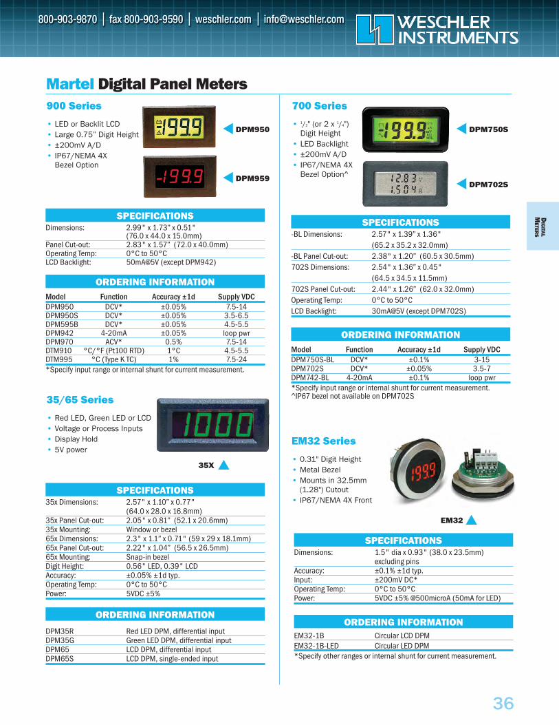
DIG
ITALM
ETERS
36
Martel Digital Panel Meters900 Series
• LED or Backlit LCD• Large 0.75” Digit Height• ±200mV A/D• IP67/NEMA 4X
Bezel Option
DPM950
DPM959Dimensions: 2.99" x 1.73” x 0.51"
(76.0 x 44.0 x 15.0mm) Panel Cut-out: 2.83" x 1.57” (72.0 x 40.0mm) Operating Temp: 0°C to 50°C LCD Backlight: 50mA@5V (except DPM942)
Model Function Accuracy ±1d Supply VDCDPM950 DCV* ±0.05% 7.5-14DPM950S DCV* ±0.05% 3.5-6.5DPM595B DCV* ±0.05% 4.5-5.5DPM942 4-20mA ±0.05% loop pwrDPM970 ACV* 0.5% 7.5-14 DTM910 °C/°F (Pt100 RTD) 1°C 4.5-5.5DTM995 °C (Type K TC) 1% 7.5-24 *Specify input range or internal shunt for current measurement.
SPECIFICATIONS
ORDERING INFORMATION
700 Series
• 1/2" (or 2 x 1/4") Digit Height
• LED Backlight • ±200mV A/D• IP67/NEMA 4X
Bezel Option^
DPM750S
DPM702S
-BL Dimensions: 2.57" x 1.39” x 1.36" (65.2 x 35.2 x 32.0mm)
-BL Panel Cut-out: 2.38" x 1.20” (60.5 x 30.5mm) 702S Dimensions: 2.54" x 1.36” x 0.45"
(64.5 x 34.5 x 11.5mm) 702S Panel Cut-out: 2.44" x 1.26” (62.0 x 32.0mm) Operating Temp: 0°C to 50°C LCD Backlight: 30mA@5V (except DPM702S)
Model Function Accuracy ±1d Supply VDCDPM750S-BL DCV* ±0.1% 3-15DPM702S DCV* ±0.05% 3.5-7DPM742-BL 4-20mA ±0.1% loop pwr *Specify input range or internal shunt for current measurement. ^IP67 bezel not available on DPM702S
SPECIFICATIONS
ORDERING INFORMATION
35/65 Series
• Red LED, Green LED or LCD• Voltage or Process Inputs• Display Hold • 5V power
35x Dimensions: 2.57" x 1.10” x 0.77" (64.0 x 28.0 x 16.8mm)
35x Panel Cut-out: 2.05" x 0.81” (52.1 x 20.6mm) 35x Mounting: Window or bezel 65x Dimensions: 2.3" x 1.1” x 0.71" (59 x 29 x 18.1mm) 65x Panel Cut-out: 2.22" x 1.04” (56.5 x 26.5mm) 65x Mounting: Snap-in bezel Digit Height: 0.56" LED, 0.39" LCD Accuracy: ±0.05% ±1d typ.Operating Temp: 0°C to 50°C Power: 5VDC ±5%
DPM35R Red LED DPM, differential input DPM35G Green LED DPM, differential input DPM65 LCD DPM, differential input DPM65S LCD DPM, single-ended input
SPECIFICATIONS
ORDERING INFORMATION
Dimensions: 1.5" dia x 0.93" (38.0 x 23.5mm) excluding pins
Accuracy: ±0.1% ±1d typ.Input: ±200mV DC* Operating Temp: 0°C to 50°C Power: 5VDC ±5% @500microA (50mA for LED)
EM32-1B Circular LCD DPM EM32-1B-LED Circular LED DPM *Specify other ranges or internal shunt for current measurement.
SPECIFICATIONS
ORDERING INFORMATION
EM32 Series
• 0.31" Digit Height• Metal Bezel• Mounts in 32.5mm
(1.28") Cutout• IP67/NEMA 4X Front
EM32
35X
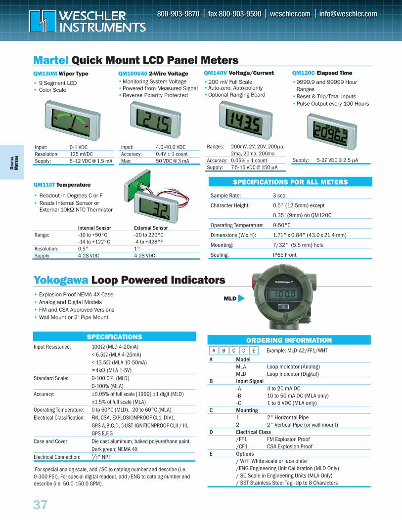
DIG
ITAL
MET
ERS
37
QM130M Wiper Type
• 9 Segment LCD• Color Scale
Input: 0-1 VDCResolution: 125 mVDCSupply: 5–12 VDC @ 1.5 mA
QM140V Voltage/Current
•200 mV Full Scale •Auto-zero, Auto-polarity•Optional Ranging Board
QM120C Elapsed Time
•9999.9 and 99999 Hour Ranges
•Reset & Trip/Total Inputs•Pulse Output every 100 Hours
QM110T Temperature
• Readout in Degrees C or F• Reads Internal Sensor or
External 10kΩ NTC Thermistor
Martel Quick Mount LCD Panel Meters
SPECIFICATIONS FOR ALL METERS
Sample Rate: 3 sec.
Character Height: 0.5" (12.5mm) except
0.35"(9mm) on QM120C
Operating Temperature: 0-50°C
Dimensions (W x H): 1.71" x 0.84" (43.0 x 21.4 mm)
Mounting: 7/32" (5.5 mm) hole
Sealing: IP65 Front
QM100V40 2-Wire Voltage•Monitoring System Voltage•Powered from Measured Signal•Reverse Polarity Protected
Input: 4.0-40.0 VDCAccuracy: 0.4V ± 1 countMax: 50 VDC @ 3 mA
Ranges: 200mV, 2V, 20V, 200µa,2ma, 20ma, 200ma
Accuracy: 0.05% ± 1 countSupply: 7.5-15 VDC @ 150 µA
Internal Sensor External SensorRange: -10 to +50°C -20 to 220°C
-14 to +122°C -4 to +428°FResolution: 0.5° 1°Supply 4-28 VDC 4-28 VDC
• Explosion-Proof NEMA 4X Case • Analog and Digital Models • FM and CSA Approved Versions • Wall Mount or 2" Pipe Mount
A ModelMLA Loop Indicator (Analog)MLD Loop Indicator (Digital)
B Input Signal-A 4 to 20 mA DC-B 10 to 50 mA DC (MLA only)-C 1 to 5 VDC (MLA only)
C Mounting 1 2" Horizontal Pipe2 2" Vertical Pipe (or wall mount)
D Electrical Class/FF1 FM Explosion Proof/CF1 CSA Explosion Proof
E Options / WHT White scale or face plate/ENG Engineering Unit Calibration (MLD Only)/ SC Scale in Engineering Units (MLA Only)/ SST Stainless Steel Tag -Up to 8 Characters
ORDERING INFORMATION
Yokogawa Loop Powered IndicatorsMLD
SPECIFICATIONSInput Resistance: 100Ω (MLD 4-20mA)
< 6.5Ω (MLA 4-20mA)< 13.5Ω (MLA 10-50mA)
~4kΩ (MLA 1-5V)Standard Scale: 0-100.0% (MLD)
0-100% (MLA)Accuracy: ±0.05% of full scale [1999] ±1 digit (MLD)
±1.5% of full scale (MLA)Operating Temperature: 0 to 60°C (MLD), -20 to 60°C (MLA)Electrical Classification: FM, CSA, EXPLOSIONPROOF CL1, DIV1,
GPS A,B,C,D, DUST-IGNITIONPROOF CLII / III,GPS E,F,G
Case and Cover: Die cast aluminum, baked polyurethane paint.Dark green; NEMA 4X
Electrical Connection: 1/2" NPT
For special analog scale, add /SC to catalog number and describe (i.e. 0-300 PSI). For special digital readout, add /ENG to catalog number anddescribe (i.e. 50.0-150.0 GPM).
A B C D E Example: MLD-A2/FF1/WHT
~
Supply: 5-27 VDC @ 2.5 µA
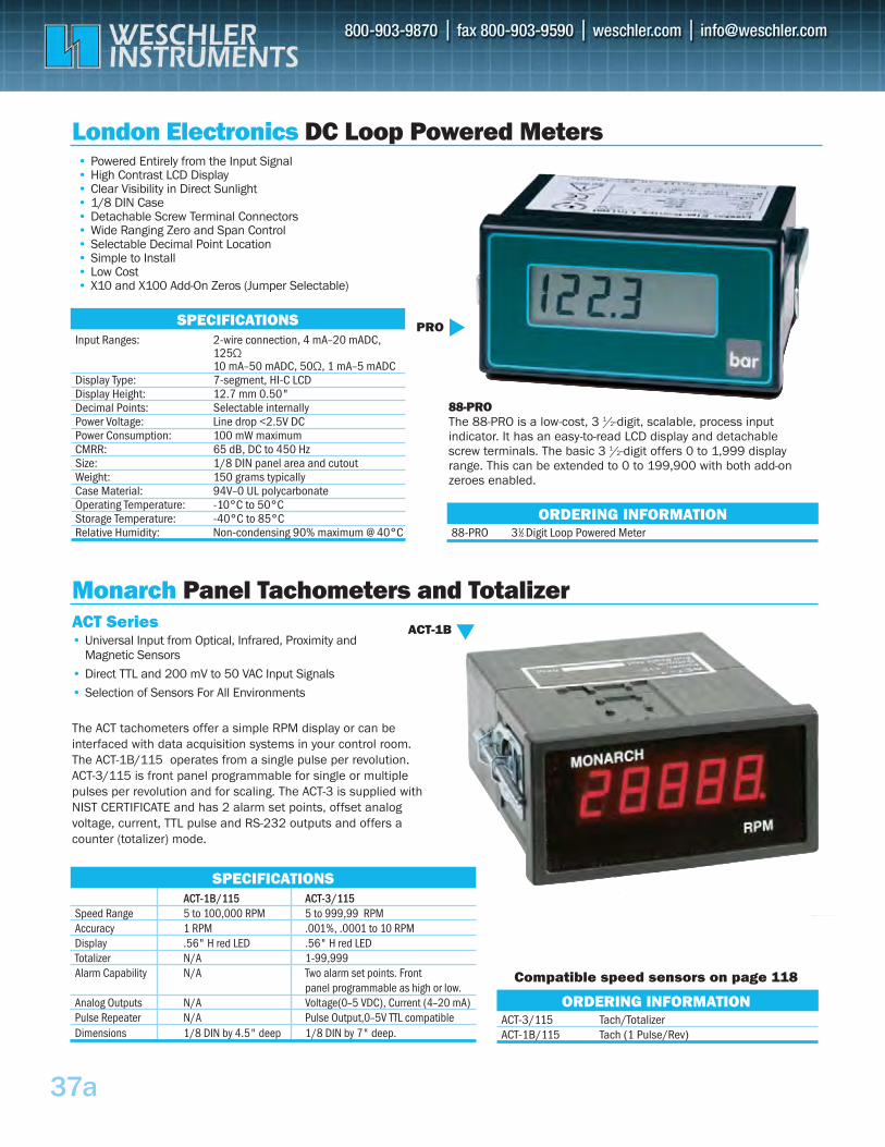
37a
Input Ranges: 2-wire connection, 4 mA–20 mADC, 125Ω 10 mA–50 mADC, 50Ω, 1 mA–5 mADC
Display Type: 7-segment, HI-C LCD Display Height: 12.7 mm 0.50"Decimal Points: Selectable internally Power Voltage: Line drop <2.5V DC Power Consumption: 100 mW maximum CMRR: 65 dB, DC to 450 HzSize: 1/8 DIN panel area and cutout Weight: 150 grams typically Case Material: 94V–0 UL polycarbonate Operating Temperature: -10°C to 50°C Storage Temperature: -40°C to 85°C Relative Humidity: Non-condensing 90% maximum @ 40°C
SPECIFICATIONS
• Powered Entirely from the Input Signal• High Contrast LCD Display• Clear Visibility in Direct Sunlight• 1/8 DIN Case• Detachable Screw Terminal Connectors• Wide Ranging Zero and Span Control• Selectable Decimal Point Location• Simple to Install• Low Cost• X10 and X100 Add-On Zeros (Jumper Selectable)
London Electronics DC Loop Powered Meters
PRO
88-PRO 31⁄2-Digit Loop Powered MeterORDERING INFORMATION
88-PRO The 88-PRO is a low-cost, 3 1/2-digit, scalable, process input indicator. It has an easy-to-read LCD display and detachable screw terminals. The basic 3 1/2-digit offers 0 to 1,999 display range. This can be extended to 0 to 199,900 with both add-on zeroes enabled.
ACT-3/115 Tach/Totalizer ACT-1B/115 Tach (1 Pulse/Rev)
ACT-1B/115 ACT-3/115Speed Range 5 to 100,000 RPM 5 to 999,99 RPMAccuracy 1 RPM .001%, .0001 to 10 RPMDisplay .56" H red LED .56" H red LEDTotalizer N/A 1-99,999 Alarm Capability N/A Two alarm set points. Front
panel programmable as high or low.Analog Outputs N/A Voltage(0–5 VDC), Current (4–20 mA) Pulse Repeater N/A Pulse Output,0–5V TTL compatible Dimensions 1/8 DIN by 4.5" deep 1/8 DIN by 7" deep.
SPECIFICATIONS
Monarch Panel Tachometers and TotalizerACT-1B
Compatible speed sensors on page 118
ORDERING INFORMATION
ACT Series • Universal Input from Optical, Infrared, Proximity and
Magnetic Sensors
• Direct TTL and 200 mV to 50 VAC Input Signals
• Selection of Sensors For All Environments
The ACT tachometers offer a simple RPM display or can be interfaced with data acquisition systems in your control room. The ACT-1B/115 operates from a single pulse per revolution. ACT-3/115 is front panel programmable for single or multiple pulses per revolution and for scaling. The ACT-3 is supplied with NIST CERTIFICATE and has 2 alarm set points, offset analog voltage, current, TTL pulse and RS-232 outputs and offers a counter (totalizer) mode.
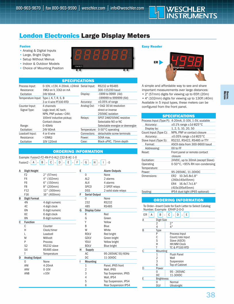
Example: Fusion2-F2-4N-P-0-AL2-232-B-AC-1-0
Fusion2 - - 0
DIG
ITALM
ETERS
38
Process Input (Type P): 4-20mA, 0-10V, 1-5V, scalableAccuracy: ±0.1% range ±1d @25°C Display by: 1, 2, 5, 10, 20, 50
Count Input (Type C): NPN, PNP or contact closureAccuracy: ±0.05% range ±1d @25°C
Slave Input (Type S): RS232, RS422, RS485 or TTYFormat: ASCII data from 300-9600 baud Addressing: 00 to FF
Reset: Front panel or remote contact closureExcitation: 24VDC, up to 30mA (except Slave) Operating 0-50°C, <95% RH non-condensing Temperature: Power: 95-265VAC, 11-30VDC Dimensions: ER2 10.3x5.8x1.8"
(260x140x45mm) ER4 16.4x7.7x1.8" (415x195x45mm)
Sealing: IP54 dust tight (IP65 optional)
Fusion• Analog & Digital Inputs• Large, Bright Digits• Setup Without Menus• Indoor & Outdoor Models• Choice of Mounting Position
A simple and affordable way to see and share important measurements over large distances:• 2" (57mm) digits for viewing up to 65ft (20m)• 4" (102mm) digits for viewing up to 130ft (40m) Available in 5 input types, these meters can be configured from the front panel.
SPECIFICATIONS
London Electronics Large Display MetersEasy Reader
ORDERING INFORMATION
SPECIFICATIONS
ORDERING INFORMATIONTo Order—Insert Code for Each Letter to Select Catalog Number. Example ER4P-2-O-O
A Digit Size2 2" 4 4"
B Type P Process Input C Count/rate Input S Slave (ASCII)H HH:MM Clock T TC & PT100 RTD
C Mounting1 Flush Panel2 Wall3 Suspension6 Top of Cabinet
D Power0 95 - 265VAC DC 11-30VDC
E Brightness0 Normal DLV Ultrabright
A B – CER
ER
Process Input: 0-10V, ±13V, 4-20mA, ±24mAResistance: 1MΩ on V, 33Ω on mA Excitation 24V 60mA
Temperature Input: Type J, K, T, R, S, B3 or 4 wire PT100 RTD
Counter Input: 4 channels Signal Type: Logic level; AC tach;
NPN, PNP pulses <24V; 100mV inductive pickup; Contact closure
Range: 0-40kHz Excitation: 24V 60mA
Loadcell Input: 4 or 6 wireResistance: >10MΩExcitation 10V 120mA
– D – E
Serial Input: RS232 or RS485300-115200 baud
Display: -1999 to 9999 (4d)-199999 to 999999 (6d)
Accuracy: ±0.05% of range Analog Out: >1kΩ 16 bit resolution
direct or inverse 250VAC isolation
Relays: SPST 2A@250VAC resistiveSelectable NO or NC Selectable energize or deenergize
Temperature: 0-50°C operating Connectors: detachable screw terminals Power: 50VA max.Case: Black uPVC, 75mm depth
A Digit HeightF2 2" (57mm) F4 4" (102mm) F6 6" (150mm) F8 8" (200mm) F12 12" (300mm) F16 16" (400mm)
B Digit Format4N 4 digit numeric 4C 4 digit clock 6N 6 digit numeric 6C 6 digit clock 8N 8 digit numeric
C FunctionC Counter H Clock/timer L Loadcell M Millivolt P Process S2 RS232 slave S4 RS485 slave T Temperature
D Analog Output0 None ANI 4-20mA ANV 0-10V ANB ±10V
E Alarm Outputs0 None AL2 2 alarms AL4 4 alarms SPCO 2 SPDT relays DSS 2 solid state relays
F Serial Output0 None 232 RS232 485 RS485
G Display ColorR Red G Green Y Yellow B Blue W White RDLV Red bright GDLV Green bright YDLV Yellow bright BDLV Blue bright
H SupplyAC 95-265VAC 50/60Hz DC 11-30VDC
I Mounting1 Panel, IP65 front2 Wall, IP653 Top Suspension, IP654 Wall, IP545 Top Suspension, IP546 Rear Suspension IP54
A – B – C – D – E – F – G – H – I
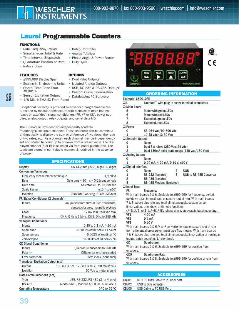
CBL01 RJ11 TO DB9 Cable to PC Com portCBL02 USB to DB9 AdapterCBL05 USB Cable to PC USB Port
DIG
ITAL
MET
ERS
39
FUNCTIONS• Rate, Frequency, Period• Simultaneous Total & Rate• Time Interval, Stopwatch• Quadrature Position or Rate• Ratio / Draw
FEATURES• ±999,999 Display Span• Scaling in Engineering Units• Crystal Time Base Error
<0.001%• Sensor Excitation Output• 1/8 DIN, NEMA-4X Front Panel
Exceptional flexibility is provided by advanced programmable fea-tures and by modular architecture with a choice of main boards(basic or extended), signal conditioners (FR, VF or QD), power sup-plies, analog output, relay outputs, and serial data I/O.
The FR module provides two independently scalablefrequency/pulse input channels. These channels can be combinedarithmetically to display the sum or difference of two flows, the ratioof two rates, etc. As a counter, each channel may be independentlyset and scaled to count up to or down from a preset value. The dis-played channel (A or B) is selected via front panel pushbutton. Thetotals are stored in non-volatile memory & retained in the absenceof power.
Display Six 14.2 mm (.56") high LED digitsConversion Technique
Frequency measurement technique 1/periodRate Gate time + 30 ms + 0-2 input periodsGate time Selectable 0 to 199.99 secScale Factor ±10 -10 to ±106
Isolation 250V RMS working, 2.3kV RMS testFR Signal Conditioner (2 channels)
Inputs AC, pulses from NPN or PNP transistors, contact closures, magnetic pickups
Level ±12 mV min, 250 Vac maxFrequency CH A: 0 Hz to 1 MHz; CH B: 0 Hz to 250 kHz
VF Signal ConditionerInputs 0-10 V, 0-1 mA, 4-20 mASpan error < 0.015% of full scale ±1 countSpan tempco < 0.003% of reading/°CZero tempco < 0.001% of full scale/°C
QD Signal ConditionerInputs Quadrature encoders to 250 kHzPolarity Differential or single-endedError correction Zero index (z-channel)
Transducer Excitation Output (std)Output 100 mA @ 5 V, 120 mA @ 10 V, 50 mA @ 24 VIsolation 50 Vdc to meter ground
Data Communications (opt)Type USB, RS-232, RS-485 (2- or 4-wire)RS-485 Modbus RTU, Modbus ASCII, or Laurel ASCII
Operating Temperature 0°C to 55°C
SPECIFICATIONS
Example: L50010FR L Laureate™ with plug-in screw terminal connectors Main Board
5 Meter with green LEDs6 Meter with red LEDs7 Extended, green LEDs8 Extended, red LEDs
Power0 85-264 Vac/90-300 Vdc1 10-48 Vdc/12-30 Vac
Setpoint Output0 None1 Dual 8 A relays (250 Vac/24 Vdc)2 Dual 130mA solid state relays (140 Vac/180 Vdc)
Analog Output0 None1 0-20 mA, 4-20 mA, 0-10 V, ±10 V
Digital Interface0 None 5 USB1 RS-232 (Isolated) 6 USB to RS-485 Converter2 RS-485 (Isolated)4 RS-485 Modbus (Isolated)
Input TypeFR FrequencyWith main boards 5 & 6: Scalable to ±999,999 for frequency, period, up/down total, interval, rate or square root of rate. With main boards 7 & 8: Above plus rate and total simultaneously, custom curve linearization, atio, draw, arithmetic functions (A*B, A/B, A/B-1, A+B, A-B), phase angle, stopwatch, batch counting.VF1 4-20 mAVF2 0-1 mAVF3 0-10 VWith main boards 5 & 6: V-to-F converter for rate or square root of rate from differential pressure or target type flow meters. With main boards 7 & 8: Above plus rate and total simultaneously, linearization of nonlinear inputs, batch counting, 1/rate (time).QD QuadratureWith main boards 5 & 6: Scalable to ±999,999 for position from encoders. QDR Quadrature RateWith main boards 7 & 8; Scalable to ±999,999 for position or rate from encoders.
ORDERING INFORMATION
Laurel Programmable Counters
OPTIONS• Dual Relay Outputs• Isolated Analog Outputs• USB, RS-232 & RS-485 Data I/O• Custom Curve Linearization• Datalogging PC Software
• Batch Controller• Analog Totalizer• Phase Angle & Power Factor• Duty Cycle
ACCESSORIES
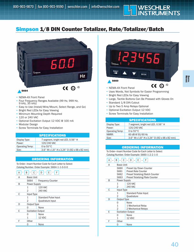
DIG
ITALM
ETERS
40
To Order—Insert Number Code for Each Letter to SelectCatalog Number. Order Example: S660-1-2-2-1-0
A Basic UnitS660 Preset Up/Down CounterS661 Preset Rate CounterS662 Preset Totalizing/Batch CounterS663 Preset Totalizing/Rate Counter
B Power Supply1 120 VAC2 240 VAC
C Input Type1 Standard Pulse Input2 Quadrature
D Output Type0 None1 1 Mechanical Relay2 2 Mechanical Relays
E Excitation Output0 None1 12 VDC
F Other0 None
To Order—Insert Number Code for Each Letter to SelectCatalog Number. Order Example: S664-1-1-0-0-0
A Basic UnitS664 Frequency Counter
B Power Supply1 120 VAC2 240 VAC
C Input Type1 Standard Pulse Input2 Quadrature input
D Output Type0 None
E Excitation Output0 None1 12 VDC
F Other0 None
SPECIFICATIONS
S664
• NEMA-4X Front Panel• Four Frequency Ranges Available (99 Hz, 999 Hz,
9 kHz, 35 kHz)• Easy to Use (Install/Wire/Mount, Select Range, and Go)• Bright Red LEDs for Easy Viewing• Minimum Mounting Depth Required• 120 or 240 VAC • Optional Excitation Output 12 VDC @ 100 mA• Modular Design• Screw Terminals for Easy Installation
Display Type: 7 segment, bright red LED, 0.56" HPower: 120/240 VACOperating Temp: 0 to 55°CSize: 3.6" W x 1.8" H x 3.24" D (92 x 48 x 82 mm)
Simpson 1/8 DIN Counter Totalizer, Rate/Totalizer/Batch
• NEMA-4X Front Panel• Uses Words, Not Symbols for Easier Programming• Bright Red LEDs for Easy Viewing• Large, Tactile Buttons Can Be Pressed with Gloves On• Standard 1/8 DIN Cutout• Up to Two 5 Amp Relays Optional• Optional Excitation Output 12 VDC• Screw Terminals for Easy Installation
S660
SPECIFICATIONSDisplay Type: 7 segment, bright red LED, 0.56" HPower: 120/240 VACOperating Temp: 0 to 55°CNMRR: 60 dB @ 50/60 HzSize: 3.6" W x 1.8" H x 3.24" D (92 x 48 x 82 mm)
ORDERING INFORMATION
A – B – C – D – E – F
ORDERING INFORMATION
A – B – C – D – E – F
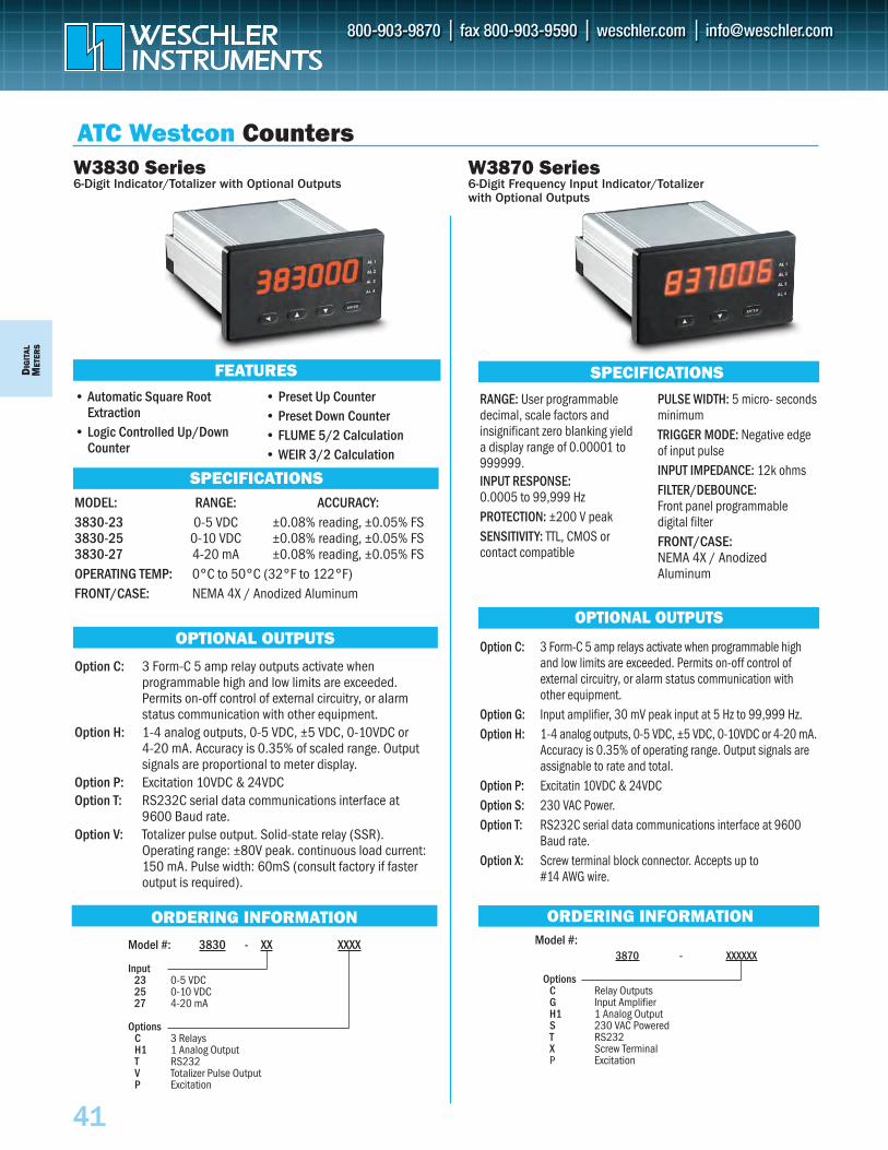
3870 - XXXXXX
OptionsC Relay OutputsG Input AmplifierH1 1 Analog OutputS 230 VAC PoweredT RS232X Screw TerminalP Excitation
PRICE Model #:$ 225
$ 6065
140N/C
6026
DIG
ITAL
MET
ERS
41
ORDERING INFORMATION
W3830 Series6-Digit Indicator/Totalizer with Optional Outputs
• Automatic Square RootExtraction
• Logic Controlled Up/DownCounter
• Preset Up Counter• Preset Down Counter• FLUME 5/2 Calculation• WEIR 3/2 Calculation
SPECIFICATIONS
OPTIONAL OUTPUTS
FEATURES
ORDERING INFORMATION
W3870 Series6-Digit Frequency Input Indicator/Totalizer with Optional Outputs
RANGE: User programmabledecimal, scale factors andinsignificant zero blanking yielda display range of 0.00001 to999999.INPUT RESPONSE:0.0005 to 99,999 HzPROTECTION: ±200 V peakSENSITIVITY: TTL, CMOS orcontact compatible
PULSE WIDTH: 5 micro- secondsminimumTRIGGER MODE: Negative edgeof input pulseINPUT IMPEDANCE: 12k ohmsFILTER/DEBOUNCE:Front panel programmable digital filterFRONT/CASE:NEMA 4X / AnodizedAluminum
SPECIFICATIONS
MODEL: RANGE: ACCURACY:3830-23 0-5 VDC ±0.08% reading, ±0.05% FS3830-25 0-10 VDC ±0.08% reading, ±0.05% FS3830-27 4-20 mA ±0.08% reading, ±0.05% FSOPERATING TEMP: 0°C to 50°C (32°F to 122°F)FRONT/CASE: NEMA 4X / Anodized Aluminum
Model #: 3830 - XX XXXX
Input23 0-5 VDC25 0-10 VDC27 4-20 mA
OptionsC 3 RelaysH1 1 Analog OutputT RS232V Totalizer Pulse OutputP Excitation
Option C: 3 Form-C 5 amp relay outputs activate when programmable high and low limits are exceeded.Permits on-off control of external circuitry, or alarm status communication with other equipment.
Option H: 1-4 analog outputs, 0-5 VDC, ±5 VDC, 0-10VDC or 4-20 mA. Accuracy is 0.35% of scaled range. Outputsignals are proportional to meter display.
Option P: Excitation 10VDC & 24VDCOption T: RS232C serial data communications interface at
9600 Baud rate.Option V: Totalizer pulse output. Solid-state relay (SSR).
Operating range: ±80V peak. continuous load current:150 mA. Pulse width: 60mS (consult factory if fasteroutput is required).
OPTIONAL OUTPUTS
Option C: 3 Form-C 5 amp relays activate when programmable highand low limits are exceeded. Permits on-off control ofexternal circuitry, or alarm status communication withother equipment.
Option G: Input amplifier, 30 mV peak input at 5 Hz to 99,999 Hz.Option H: 1-4 analog outputs, 0-5 VDC, ±5 VDC, 0-10VDC or 4-20 mA.
Accuracy is 0.35% of operating range. Output signals are assignable to rate and total.
Option P: Excitatin 10VDC & 24VDCOption S: 230 VAC Power.Option T: RS232C serial data communications interface at 9600
Baud rate.Option X: Screw terminal block connector. Accepts up to
#14 AWG wire.
ATC Westcon Counters
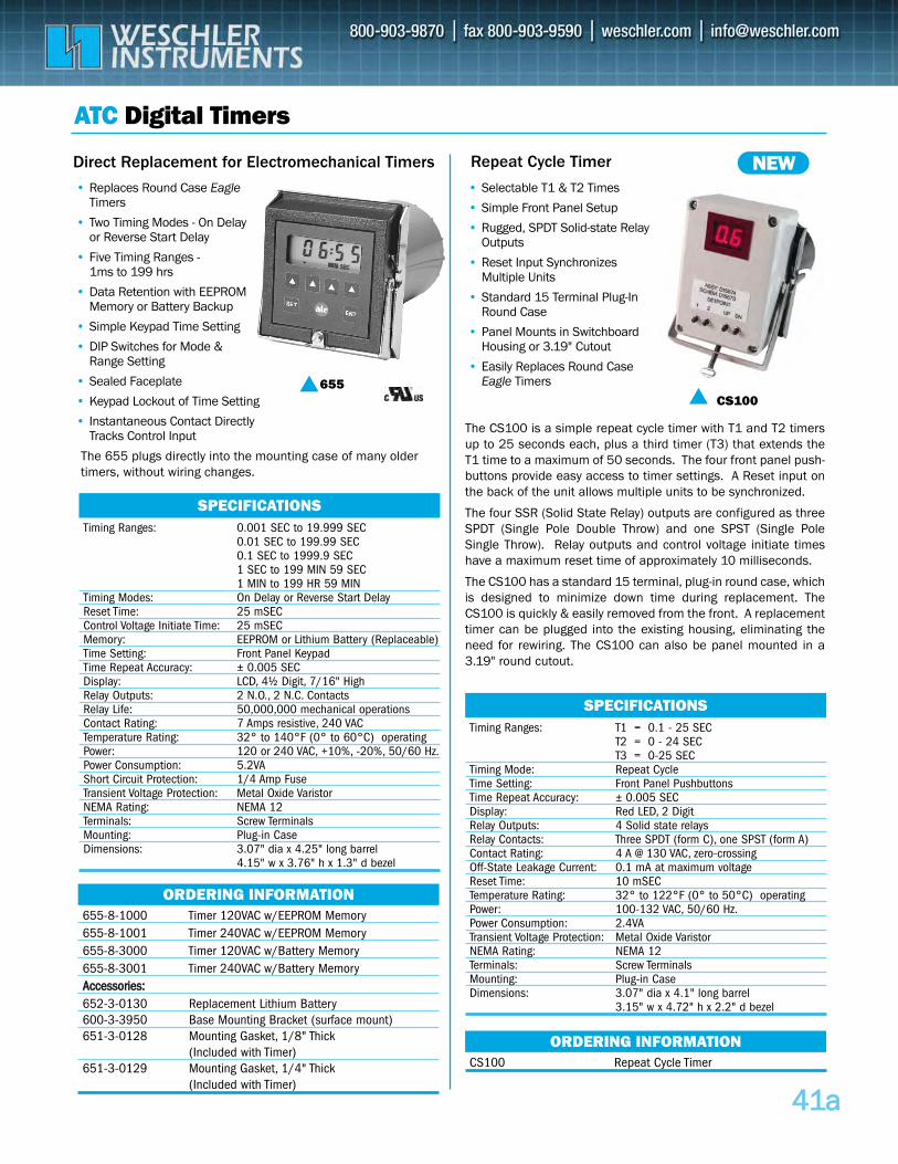
4411aa
655-8-1000 Timer 120VAC w/EEPROM Memory 655-8-1001 Timer 240VAC w/EEPROM Memory 655-8-3000 Timer 120VAC w/Battery Memory 655-8-3001 Timer 240VAC w/Battery Memory AAcccceessssoorriieess::652-3-0130 Replacement Lithium Battery 600-3-3950 Base Mounting Bracket (surface mount) 651-3-0128 Mounting Gasket, 1/8" Thick
(Included with Timer) 651-3-0129 Mounting Gasket, 1/4" Thick
(Included with Timer)
ATC Digital Timers
Direct Replacement for Electromechanical Timers Repeat Cycle Timer
• Replaces Round Case EagleTimers
• Two Timing Modes - On Delay or Reverse Start Delay
• Five Timing Ranges -1ms to 199 hrs
• Data Retention with EEPROMMemory or Battery Backup
• Simple Keypad Time Setting
• DIP Switches for Mode & Range Setting
• Sealed Faceplate
• Keypad Lockout of Time Setting
• Instantaneous Contact Directly Tracks Control Input
• Selectable T1 & T2 Times
• Simple Front Panel Setup
• Rugged, SPDT Solid-state RelayOutputs
• Reset Input Synchronizes Multiple Units
• Standard 15 Terminal Plug-In Round Case
• Panel Mounts in Switchboard Housing or 3.19" Cutout
• Easily Replaces Round Case Eagle Timers655
ORDERING INFORMATION
CS100 Repeat Cycle Timer
ORDERING INFORMATION
CS100
NEW
SPECIFICATIONSTiming Ranges: 0.001 SEC to 19.999 SEC
0.01 SEC to 199.99 SEC0.1 SEC to 1999.9 SEC1 SEC to 199 MIN 59 SEC1 MIN to 199 HR 59 MIN
Timing Modes: On Delay or Reverse Start DelayReset Time: 25 mSECControl Voltage Initiate Time: 25 mSECMemory: EEPROM or Lithium Battery (Replaceable)Time Setting: Front Panel KeypadTime Repeat Accuracy: ± 0.005 SECDisplay: LCD, 4½ Digit, 7/16" HighRelay Outputs: 2 N.O., 2 N.C. ContactsRelay Life: 50,000,000 mechanical operationsContact Rating: 7 Amps resistive, 240 VACTemperature Rating: 32° to 140°F (0° to 60°C) operatingPower: 120 or 240 VAC, +10%, -20%, 50/60 Hz.Power Consumption: 5.2VAShort Circuit Protection: 1/4 Amp FuseTransient Voltage Protection: Metal Oxide VaristorNEMA Rating: NEMA 12Terminals: Screw TerminalsMounting: Plug-in CaseDimensions: 3.07" dia x 4.25" long barrel
4.15" w x 3.76" h x 1.3" d bezel
SPECIFICATIONSTiming Ranges: T1 = 0.1 - 25 SEC
T2 = 0 - 24 SECT3 = 0-25 SEC
Timing Mode: Repeat CycleTime Setting: Front Panel PushbuttonsTime Repeat Accuracy: ± 0.005 SECDisplay: Red LED, 2 Digit Relay Outputs: 4 Solid state relaysRelay Contacts: Three SPDT (form C), one SPST (form A)Contact Rating: 4 A @ 130 VAC, zero-crossing Off-State Leakage Current: 0.1 mA at maximum voltageReset Time: 10 mSECTemperature Rating: 32° to 122°F (0° to 50°C) operatingPower: 100-132 VAC, 50/60 Hz.Power Consumption: 2.4VATransient Voltage Protection: Metal Oxide VaristorNEMA Rating: NEMA 12Terminals: Screw TerminalsMounting: Plug-in CaseDimensions: 3.07" dia x 4.1" long barrel
3.15" w x 4.72" h x 2.2" d bezel
The 655 plugs directly into the mounting case of many oldertimers, without wiring changes.
The CS100 is a simple repeat cycle timer with T1 and T2 timersup to 25 seconds each, plus a third timer (T3) that extends theT1 time to a maximum of 50 seconds. The four front panel push-buttons provide easy access to timer settings. A Reset input onthe back of the unit allows multiple units to be synchronized.
The four SSR (Solid State Relay) outputs are configured as threeSPDT (Single Pole Double Throw) and one SPST (Single PoleSingle Throw). Relay outputs and control voltage initiate timeshave a maximum reset time of approximately 10 milliseconds.
The CS100 has a standard 15 terminal, plug-in round case, whichis designed to minimize down time during replacement. TheCS100 is quickly & easily removed from the front. A replacementtimer can be plugged into the existing housing, eliminating theneed for rewiring. The CS100 can also be panel mounted in a3.19" round cutout.
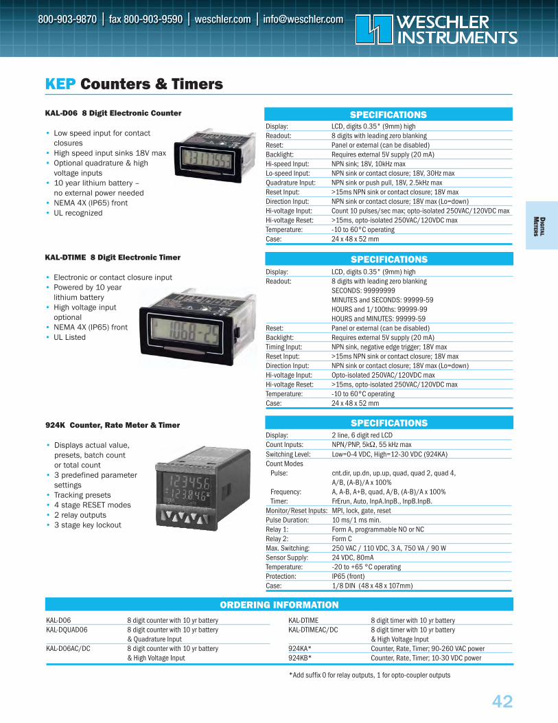
DIG
ITALM
ETERS
42
KEP Counters & Timers
KAL-D06 8 Digit Electronic Counter
• Low speed input for contact closures
• High speed input sinks 18V max• Optional quadrature & high
voltage inputs• 10 year lithium battery –
no external power needed• NEMA 4X (IP65) front• UL recognized
Display: LCD, digits 0.35" (9mm) highReadout: 8 digits with leading zero blanking Reset: Panel or external (can be disabled)Backlight: Requires external 5V supply (20 mA) Hi-speed Input: NPN sink; 18V, 10kHz max Lo-speed Input: NPN sink or contact closure; 18V, 30Hz maxQuadrature Input: NPN sink or push pull, 18V, 2.5kHz maxReset Input: >15ms NPN sink or contact closure; 18V maxDirection Input: NPN sink or contact closure; 18V max (Lo=down)Hi-voltage Input: Count 10 pulses/sec max; opto-isolated 250VAC/120VDC max Hi-voltage Reset: >15ms, opto-isolated 250VAC/120VDC max Temperature: -10 to 60°C operatingCase: 24 x 48 x 52 mm
SPECIFICATIONS
KAL-DTIME 8 Digit Electronic Timer
• Electronic or contact closure input• Powered by 10 year
lithium battery• High voltage input
optional• NEMA 4X (IP65) front• UL Listed
Display: LCD, digits 0.35" (9mm) highReadout: 8 digits with leading zero blanking
SECONDS: 99999999MINUTES and SECONDS: 99999-59HOURS and 1/100ths: 99999-99HOURS and MINUTES: 99999-59
Reset: Panel or external (can be disabled)Backlight: Requires external 5V supply (20 mA)Timing Input: NPN sink, negative edge trigger; 18V max Reset Input: >15ms NPN sink or contact closure; 18V maxDirection Input: NPN sink or contact closure; 18V max (Lo=down)Hi-voltage Input: Opto-isolated 250VAC/120VDC max Hi-voltage Reset: >15ms, opto-isolated 250VAC/120VDC max Temperature: -10 to 60°C operatingCase: 24 x 48 x 52 mm
924K Counter, Rate Meter & Timer
• Displays actual value, presets, batch count or total count
• 3 predefined parameter settings
• Tracking presets • 4 stage RESET modes • 2 relay outputs • 3 stage key lockout
Display: 2 line, 6 digit red LCD Count Inputs: NPN/PNP, 5kΩ, 55 kHz maxSwitching Level: Low=0-4 VDC, High=12-30 VDC (924KA)Count Modes
Pulse: cnt.dir, up.dn, up.up, quad, quad 2, quad 4, A/B, (A-B)/A x 100%
Frequency: A, A-B, A+B, quad, A/B, (A-B)/A x 100%Timer: FrErun, Auto, InpA.InpB., InpB.InpB.
Monitor/Reset Inputs: MPI, lock, gate, resetPulse Duration: 10 ms/1 ms min.Relay 1: Form A, programmable NO or NCRelay 2: Form CMax. Switching: 250 VAC / 110 VDC, 3 A, 750 VA / 90 WSensor Supply: 24 VDC, 80mATemperature: -20 to +65 °C operatingProtection: IP65 (front)Case: 1/8 DIN (48 x 48 x 107mm)
ORDERING INFORMATION
SPECIFICATIONS
SPECIFICATIONS
KAL-D06 8 digit counter with 10 yr batteryKAL-DQUAD06 8 digit counter with 10 yr battery
& Quadrature InputKAL-D06AC/DC 8 digit counter with 10 yr battery
& High Voltage Input
KAL-DTIME 8 digit timer with 10 yr batteryKAL-DTIMEAC/DC 8 digit timer with 10 yr battery
& High Voltage Input924KA* Counter, Rate, Timer; 90-260 VAC power924KB* Counter, Rate, Timer; 10-30 VDC power
*Add suffix 0 for relay outputs, 1 for opto-coupler outputs

42a
To Order—Insert Number Code for Each Letter to Select Catalog Number Order Example: 904K-A-0-A
A Basic Unit 903K Single Output 904K Dual Outputs
B Input VoltageA 115 VAC B 230 VAC C 11 to 30 VDC D 24 VAC E 48 VAC
C Outputs0 Relay 1 Opto-Isolated collector and emitter
D Options— Blank if None A Backlit LCD Display (904K only)
KEP Counter/Timer
LCD preset add/subtract counter, timer, frequency meter
903K/904K Series• 6-Digit Counter, Timer or
Frequency Meter
• 2 Preset Values (Type 903K 1 Preset)
• Input Scaling(0.0001 to 9.9999) Multiplier
• 2-Line LCD Display
• Count and Preset Range of -999999 to 999999
• Add or Subtract Count Control
• AC or DC Operation
• Secondary Preset Batch Counter (904K)
• 24 VDC to Power Peripherals
904K
SPECIFICATIONSDisplay: 6-digit, 2-line, 7 segment LCD with sign
Preset: Type 904 two preset values
Type 903 one preset value
Supply voltage: 115 VAC, 230 VAC, 48 VAC or 24 VAC
(tolerance ± 10%) or 11 to 30 VDC
Housing: 48 x 48 mm DIN
Protection: IP 65 (front)
Power Supply: 24 VDC, 80 mA
ORDERING INFORMATION
A – B – C – D
To Order—Insert Number Code for Each Letter to Select Catalog Number. Order Example: INT69RT-A-L-1-A-C1
A Basic Unit INT69RT Ratemeter/Totalizer INT69R Ratemeter Only INT69PM2 Process Monitor
Displays from -19999 to +49999 INT69T Totalizer Only
B Operating VoltageA 110 VAC ±15% or 12 to 24 VDCB 220 VAC ±15% or 12 to 24 VDC
C Inputs — Blank for INT69PM2 L Linear (standard)S Square Law (optional)
D Control Outputs1 2-Open Collector Outputs (standard) 2 2–10 Amp Form C Relays (optional)
E Options (Multiple Options Available)A Analog Output (4–20 mA)D Rate per Day, Hour or Minute C1 RS-232 communications C2 RS-422 communications
Intellect-69 Series• High/Low Scaling from Front Panel• 2 Set Points Assignable To Rate or Total• Display Rate (Pressure, Level, Watts, Etc.),
Peak and Valley and Integrated Total• 0–5V, 0–10V, 1–5V, 4–20 mA or 0–20 mA Analog Input • NEMA 4X/IP 65 Front Panel• +24V Output for Peripherals• RS-422/RS-232 Serial Communications• 4–20 mA Output• Square Root Extraction• Optional Rate Per Day Feature
KEP Totalizer/Rate MeterRatemeter/totalizer/process monitor from analog inputs
INT69RT
ORDERING INFORMATION
A – B – C – D – E
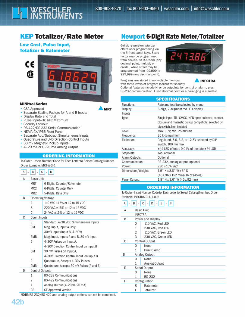
6-digit ratemeter/totalizer offers user programming via the 5 front-panel keys. Scale factor may be programmed from -99,999 to 999,999 (any decimal point, multiply or divide), while offset may be programmed from -99,999 to 999,999 (any decimal point).
Programs are stored in non-volatile memory, with three levels of program lockout for security. Optional features include Hi or Lo setpoints for control or alarm, plus RS-232 communication. Fixed decimal point or autoranging is standard.
42b
To Order—Insert Number Code for Each Letter to Select Catalog Number. Order Example: MRT-A-3-1
A Basic UnitMRT 6-Digits, Counter/Ratemeter MC2 6-Digits, Counter Only MR2 5-Digits, Rate Only
B Operating VoltageA 110 VAC ±15% or 12 to 15 VDC B 220 VAC ±15% or 12 to 15 VDC C 24 VAC ±15% or 12 to 15 VDC
C Count Inputs3 Standard, 4–30 VDC Simultaneous Inputs 3M Mag. Input, Input A Only,
30mV Input (Input B, 4–30V) 3MB Mag. Input, Inputs A and B, 30 mV input 5 4–30V Pulses on Input A,
4–30V Direction Control Input on Input B5M 30 mV Pulses on Input A,
4–30V Direction Control Input on Input B9 Quadrature, Accepts 4–30V Pulses 9MB Quadrature, Accepts 30 mV Pulses (A and B)
D Control Outputs1 RS-232 Communications2 RS-422 Communications A Analog Output (4–20/0–20 mA)CE CE Approved Version
NOTE: RS-232/RS-422 and analog output options can not be combined.
MINItrol Series• CSA Approved• Separate Scaling Factors for A and B Inputs• Display Rate and Total• Pulse Input—10 kHz Maximum• Security Lockout• RS-422/RS-232 Serial Communication • NEMA-4X/IP65 Front Panel• Separate Add/Subtract Simultaneous Inputs• Quadrature and U/D Direction Control Inputs• 30 mV Magnetic Pickup Inputs• 4–20 mA or 0–20 mA Analog Output
KEP Totalizer/Rate MeterLow Cost, Pulse Input, Totalizer & Ratemeter
MRT
ORDERING INFORMATION
A – B – C – D
Newport 6-Digit Rate Meter/Totalizer
SPECIFICATIONSFunctions: Rate and totalize selected by menuDisplay: 6-digit, 7-segment red LED displayInputs Type: Single input. TTL, CMOS, NPN open collector, contact
closure and magnetic pickup compatible; selected by dip switch. Non-isolated
Level: Max. 60V; min. 25 mV rms Frequency: 30 kHz maximum Excitation: Regulated, 5.0, 8.2, or 12.5V selected by DIP
switch, 100 mA maxAccuracy: ± 1/2 LSD of total; 0.01% of the rate ± 1/2 LSD Setpoints: Two, optional Alarm Outputs: Optional Communication: RS-232, analog output, optional Power: 230 ±15% VAC Dimensions/Weight: 1.9" H x 3.8" W x 6" D
(48 x 96 x 152 mm)/16 oz (454g)Panel Cutout: 1.8" H x 3.6" W (45 x 92 mm)
To Order—Insert Number Code for Each Letter to Select Catalog Number. Order Example: INFCTRA-0-1-1-0-R
A Basic UnitINFCTRA
B Power and Display0 115 VAC, Red LED 1 230 VAC, Red LED 2 115 VAC, Green LED 3 230 VAC, Green LED
C Control Output0 None 1 Dual 6 Amp
D Analog Output0 None 1 Analog Output
E Serial Output0 None 1 RS-232
F ConfigurationR Ratemeter T Totalizer
ORDERING INFORMATION
A – B – C – D – E – F
INFCTRA