Embed Size (px)
Citation preview

Page 1 of 12
West Gate Bridge Strengthening Project
1. Introduction From the time of its opening in 1978 the West Gate Bridge has been a critical element in the road network of Melbourne. It provides the only major crossing of the lower section of the Yarra River that connects the Melbourne CBD, the Port of Melbourne and the eastern suburbs with the rapidly developing western suburbs, the regional city of Geelong and the popular tourist destinations along the western coast.
In 2006 the State Government of Victoria announced a major project to carry out essential strengthening of the bridge to ensure the long term sustainability of the structure and ensure that it continued to safely cater for the current and future demands of both commuter and freight traffic in compliance with modern day bridge loading and design standards. The strengthening project was to be planned to be carried out over a 10 year period consistent with the approach adopted for the strengthening of similar bridges elsewhere around the world.
At the time the West Gate Bridge carried approximately 160,000 vehicles per day, with nearly 15% of these being commercial vehicles. This volume compares with the 40,000 vehicles per day that used the bridge when it was first opened to traffic in 1978. Furthermore peak period volumes for both eastbound and westbound traffic had been growing at a steady 3-5% over recent years resulting in significant congestion on the bridge and its approaches.
Within Melbourne’s road network the M1 corridor forms the main arterial spine connecting residential and industrial areas east and west of the city with the central business district and the Port of Melbourne. The M1 is identified as a freight corridor of national economic significance and the West Gate Bridge is a critical element of the corridor. In response to concerns about the increasing congestion along the route, at the same time but independent of deliberations over the need to strengthen the bridge, the State Government entered into a contract with toll road operator, Transurban, to complete a $1.5bn upgrade of the M1 over a length of 75km either side of the bridge. This much broader project was to be delivered within 5 years, including essential works to increase peak hour capacity across West Gate Bridge.
2. A Brief History of West Gate Bridge
Planning for a crossing of the lower Yarra River started in 1955 with construction works commencing in 1966. The 1960’s and 1970’s marked a significant era globally in the development of major long span bridge crossings of estuaries and navigable rivers. New structural design ideas, techniques and construction methods that pushed the boundaries of engineering knowledge at the time resulted in lighter structures and longer spans.
Tragically, within the space of 12 months, three steel box girder bridges; Milford Haven Bridge in West Wales, West Gate Bridge in Australia and South River Bridge in Koblenz, Germany; collapsed during construction with significant loss of life. The West Gate Bridge collapse in 1970 in which 35 people lost their lives, remains Australia’s worst industrial accident.
Following its collapse, and a Royal Commission into the collapse, the West Gate Bridge was re-designed to take account of contemporary research, current international best practice, traffic loading levels relevant at the time and the findings of the UK based Merrison Committee. The Merrison Committee, which was formed following the collapse of the Milford Haven Bridge, was tasked with producing revised rules for the design and workmanship of steel box girder bridges.
The bridge was eventually opened to traffic in 1978. Since then, the legal weight of commercial vehicles using the bridge has more than doubled, and their configurations have moved from predominantly shorter, rigid axle trucks to longer and heavier articulated vehicles.

Page 2 of 12
The West Gate Bridge is 2.5km long and is made up of three different structural types:
a) composite steel beam and concrete deck approach spans;
b) pre-stressed concrete box girder viaducts, and;
c) Central, cable-stayed steel box girder with orthotropic steel deck section.
Figs 1 and 2 below show the general arrangement of the bridge and a typical cross-section prior to the strengthening project.
Fig 1 - Arrangement
Fig 2 – Cross-section prior to bridge strengthening
3. Objectives of the Strengthening Project Management of West Gate Bridge is the responsibility of VicRoads, the state road authority for

Page 3 of 12
Victoria. In mid-2004 VicRoads initiated a structural review of the bridge which indicated that some components of the bridge did not theoretically comply with current bridge design codes under certain extreme load conditions. Following its own investigations, and discussions with internationally recognized experts in the assessment and strengthening of major steel structures, VicRoads made application for funding to the Victorian Government identifying the West Gate Bridge Strengthening Project as a high priority.
Resulting reports recommended the conversion of the existing 2.5m wide emergency stopping lane and standardization of lane widths across the bridge at 3.2m to provide a 5th lane in each direction. The final roadway cross section is shown in fig 3 below.
Fig 3 – Bridge cross-section
In addition, the strengthening project was extended to include the installation of non-scalable public safety barriers along the edges of the bridge over its full length.
The objectives of the strengthening project had therefore grown from the original intent but the timeline for completion had shrunk from 10 years to less than 5 years as the government was committed to providing 5 lanes in the peak directions by 30 June 2011.
Thus the primary objectives of the strengthening project were to:
o Strengthen West Gate Bridge to ensure the long term sustainability of the structure so that it continues to safely cater for the current and future demands of commuter and freight traffic in compliance with modern day bridge loading and design standards.
o Reduce congestion on the bridge by increasing the traffic capacity of the bridge from 4 lanes to 5 lanes in each direction.
o Improve the public and traffic safety across the bridge through the construction of suicide prevention barriers and the provision of refurbished and upgraded outer traffic barriers.
4. The Design and Construction Process In July 2007 VicRoads appointed a team to commence detailed structural analysis and assessment option development, business case development, procurement and implementation of the necessary strengthening. In recognition of the unique challenges and complexity of the project, and the added time imperatives, VicRoads chose to adopt a progressive Alliance model for delivery of the project.

Page 4 of 12
The initial stages were undertaken using a Design Development Alliance to mobilise the highly specialized skills required to undertake the detailed investigations, modeling, analysis, design, constructability assessments and estimating. Through an exhaustive selection process VicRoads entered into an alliance with well regarded local consultants, Sinclair Knight Merz, and London based consultants, Flint and Neill Partnership, who are internationally recognized for their work on the strengthening of similar steel bridges in the UK and Europe. Construction firm, John Holland Ltd, was chosen to join the Alliance during the latter stages of the business case preparation to provide advice on constructability and construction estimating.
In November 2007 the West Gate Bridge Strengthening Alliance commenced work on the complex analysis and option development. In December 2008 the Alliance completed the detailed Business Case for submission to government for final approval to scope and budget. Following the government approval all members of the Alliance were invited to form an alliance going forward to complete the strengthening project.
The choice of an alliance model for the project delivery stages proved to be a very wise decision as the complexity built in to the existing bridge, including the strengthening following the 1970 collapse, proved to be far more challenging to deal with than originally envisaged.
5. Bridge Strengthening Works
5.1 General
Application of current design standards was deemed inappropriate because of the unique characteristics of the bridge. Bridge specific assessment criteria were therefore developed. The Bridge Specific Assessment Live Loading (BSALL) was derived from a probabilistic analysis of existing traffic loads. The end result was a design loading that was greater than that for which the bridge was originally designed but less than the current standard SM1600 loading.
For the full length of the bridge, the epoxy asphalt on the emergency lane was replaced with SMA (stone mastic asphalt) and the outer road traffic barriers were upgraded.
Other works included the upgrade of the HV and LV electrical system, replacement of central median light masts, installation of flagpoles and flags and an upgraded security system
5.2 Steel Bridge
The following summarises the works undertaken on the steel bridge:
Installation of new openings to box girder vertical panels inside the bridge to improve access Enlargement of deck access holes Introduction of access openings in the soffit Construction of compliant walkway within the bridge Addition of significant amounts of small steel components, using bolted connections, to the
existing stiffeners inside the bridge Strengthening of longitudinal and transverse bolted splices Installation of external sloping props to provide added support to the cantilevers Installation of post-tensioning Tower and diaphragm strengthening Strengthening of bearings
One of the first tasks with the design was to compile a single record of constructed details that drew together information from the checkered history of the bridge.
5.3 Concrete Bridge
The strengthening of the concrete viaducts includes:
Introduction of additional access openings in the soffit of the eastern viaduct

Page 5 of 12
Enlarging deck access openings Carbon fibre reinforced polymer (CFRP) applied externally to the box girder and the cantilevers; Longitudinal external post tensioning installed inside the box girder.
5.4 Public Safety Barrier
Public safety barriers (PSBs) were installed along the length of the bridge (fig 4). The PSB’s posts were aligned with barrier posts and connected to end of cantilevers with a bolted bracket connection on both the steel and the concrete bridges.
All of the bridge expansion and contraction is taken at the junction between the steel and concrete bridges at Piers 10 and 15. A special detail was developed at the bridge expansion joint to accommodate these very large bridge movements. It comprises two interconnected cantilevered panels that slide past each other.
5.5 Freeway Management System Gantries
Being part of the section of freeway covered by the M1 Freeway Management System (FMS), four gantries (fig 5) were required on the bridge viaduct, as well as gantries just off the bridge, for mounting variable Lane Use Management Signs. Arriving at a concept for the gantries and accommodation of the loads they applied to a structure not designed originally for such loads presented both a design and constructability challenge.
6. The Logistical Challenge The success of most construction projects depends largely on arranging all the materials and the crew to be at the right place at the right time in an efficient and cost effective way. At the commencement of the West Gate Bridge strengthening project the access to the bridge was highly restricted, as the 1960’s design of the bridge could not have foreseen such a major strengthening project. Not only was the access restricted but the bridge had to remain open throughout the project with limited lane closures during only off peak periods. To make a success of this project, the project team had to go to the extraordinary lengths of reviewing the installation method of every piece of the strengthening work and then finding the best way to get the materials and the crew to the workface.
Fig. 5. FMS gantry Fig. 4. Public Safety Barrier

Page 6 of 12
7. Access around the site
7.1 Introduction
The access into the bridge had been unaltered from the 1970’s as constructed details. The available access to the inside of the bridge consisted of eleven small hatches in the centre median of the steel bridge which were only accessible during lane closures and just one hatchway at the lower end of each of the concrete viaduct in the soffit. The access to the external areas of the bridge was by means of four aging gantries on the steel bridge with no external access provision whatsoever to the concrete viaducts.
The key to success of the project was to maximise the access to both the internal and external areas whilst avoiding any requirement for lane closures. To maximise efficiency of the deployment of labour and materials, five separate site offices and messing facilities were established; two sites were established under the bridge at the viaduct abutments (1 and 27) and another two were established under the bridge near to the transition piers 10 and 15 (junction between the concrete viaduct and the steel cable stayed bridge). The fifth site was established adjacent to the freeway where the traffic management teams were housed.
7.2 Access into the Structures
At the viaduct abutments the hatchways which pre-existed in the soffit were inadequately sized for the purposes of executing the works inside the viaduct. The local area around the hatchway was strengthened and the hole enlarged to provide improved access. System scaffold stairs were built to allow access to the hatchways which were at a height of seven metres above the ground level.
There were no access holes in the concrete viaducts at the Transition Piers (10 and 15) and although it was preferred to add a hole at these locations, it was only on the Eastern viaduct at Pier 15 where to do so was reasonably feasible. Fortunately the majority of the strengthening work was on the Eastern viaduct.
With the only pre-existing access to the steel bridge being in the centre median area, it was essential that new access ways were created which could be utilised without the need for lane closures. Steel strengthening plates were bolted to the steel bridge soffit near the Transition Piers (Piers 10 and 15), these plates enabled new access ways to be cut in the bottom flange panel to provide personnel and a materials access points into the box girder at both ends of the steel bridge.
The bridge soffit at the Transition Piers is approximately 45m above ground level. To gain access to the new access ways into the box girder 20-person, rack and pinion construction hoists were installed at both Transition Piers. With a temporary platform just below the bridge soffit cantilevered off the Transition Pier, personnel were able to alight from the Alimak hoist and make their way up into the steel bridge box girder.
7.3 Dedicated Construction Lane
The bridge had been operated since its opening with four traffic lanes and an emergency lane in each direction. A basic requirement of the project was for the bridge to be strengthened to allow the emergency lane to be used as a full traffic lane thereby providing five traffic lanes in each direction with no emergency lane. To provide access to the external areas of the bridge, the emergency lane was converted into the “construction lane” with the addition of temporary steel and concrete New Jersey Barriers along the full length of the bridge in each direction. These barriers separated the site from the flowing traffic and allowed work to be executed at any time of the day (or night) without lane closures. To further delineate the site and to reduce the risk of suicide attempts, it was decided to provide full fencing along the top of the barriers.
The works to the external areas of the bridge (carbon fibre strengthening, new cantilever props for the steel bridge and public safety barriers) needed in excess of 200 personnel to access the 16 work fronts across the bridge every day. All these work fronts were accessed from the construction lane and all personnel accessed the lane from additional stairways near the abutments and from purpose built hanging stairways that connected the temporary Alimak platforms to the construction lane at the transition piers

Page 7 of 12
7.4 .Internal Access throughout the bridge
Improvement of internal access through the steel bridge was one of the first tasks undertaken. New walkways were installed in the bridge to allow workers to traverse the entire length of the bridge above all the transverse stiffeners. To facilitate passage through diaphragms and inner webs, the existing manholes were enlarged at the diaphragms and new larger openings provided through the inner webs at specific locations. The only exceptions to this improvement in internal access were the openings in the diaphragms over the piers. Because of the critical role these four diaphragms play in the support of the bridge, there was no practical way of enlarging these openings.
Fig. 7. Enlarged inner web manholes (left), diaphragm manholes and new walkway (middle) and diaphragm opening at piers (right).
The original median deck openings were also enlarged to allow larger sized materials to be delivered into the bridge.
The improvements to the internal access now provide a useful legacy for future maintenance work.
7.5 Access Facilities for Personnel
With a peak work force of over 700, the efficient distribution and circulation of people around the site was essential to the success of the project. The potential time lost whilst personnel waited for the Alimak hoist or could not access their work due to weather prompted the implementation of some exceptional measures.
Between the ground level messing facilities and the Alimak hoists, covered walkways consisting of end-to-end shipping containers, with their doors open and rear wall removed, provided all weather access to the hoist. At Pier 10, a public dual carriageway road intersected the site between the
Fig. 6. Temporary steel (left) and concrete barriers (right) separating the construction lane

Page 8 of 12
ground level messing facilities and the Alimak hoist. To provide safe access for personnel, a footbridge was constructed using a 33 metre long modified sign gantry for the main span, along with scaffolding to provide stair access at each of its ends.
Fig. 8. Temporary Pier 10 (Hyde Street) Footbridge.
To minimise downtime for the teams working inside the bridge, particularly the time taken for meal breaks, the project undertook its single largest temporary facility provision by constructing messing and change facilities on birdcage scaffolds just below the soffit of the steel bridge. Two of these facilities were constructed, one at Pier 10 and one at Pier 15, each 45m above ground level, each with messing, changing and toilet facilities for 100 people.
Fig. 9. Temporary Messing Facilities at Pier 15.
8. Temporary Facilities and Specialist Equipment
8.1 Services
The only services that were available at the start of the project were power and internal lighting systems that dated from the time of bridge construction. Neither of these existing services was adequate for the project’s needs or compliant with current standards. Whilst maintaining the existing services, new temporary electrical and emergency lighting systems were installed throughout the entire length of the bridge. These two systems were later handed over to the asset owner to provide a legacy for future maintenance work. On the ground, temporary electrical systems were installed to supply the site office and messing facilities.
The platforms that were suspended under the bridge to access the external strengthening works each carried a generator sufficient to supply its individual power needs. To provide water to these

Page 9 of 12
platforms, both for drinking and project works e.g. wet blasting, a potable water system was installed along the bridge handrail which provided a pumped water supply to all work locations.
The need for extensive internal and localised external blasting to remove the paint systems required innovative solutions to accommodate the large blasting equipment needed to execute the works. For the internal blasting, where red lead paint had to be removed, the blasting equipment was mounted on a semi-trailer that was driven to the nearest available access hatch during a night time lane closure. A similar semi-trailer with a vacuum recovery system was also used to collect the recovered blasting medium and paint dust. Red lead paint dust presents a significant potential health hazard and the procedure for vacuum recovery of the dust was part of the extensive measures implemented to mitigate the risk to personnel.
To enable blasting on the external faces, blasting and vacuum recovery hoses with control cables were suspended from the access platforms on catenary wires. The blasting equipment and vacuum recovery semi-trailers were moved to wherever blasting was required. For the external blasting over the Yarra River, blasting service hoses were run from the ground on the east side and supported on a catenary to the bridge deck where they then ran along the bridge handrail to the access platforms moving across over the river.
8.2 Lifting Gear
Custom-designed mobile hydraulic lifting tugs were installed on the platforms suspended under the bridge to lift the bottom steel bracket for the new cantilever props into position for fixing to the bottom flange of the bridge. This lifting tug was highly effective and minimised the manual handling required for the works. For the top steel bracket for the cantilever props a proprietary mobile, manually operated, forklift was modified for lifting the 60kg piece 3 metres up on to the bridge cantilever beam.
Fig. 10. Mobile hydraulic lifting tug lifting a bottom steel bracket into position
8.3 APS Platforms & Davits
The project required a significant amount of work to be undertaken to the underside of the steel and concrete bridges. This work included placement of carbon fibre, installation of brackets for the public safety barrier, replacement and reinforcement of bolted splices and installation of cantilever props. With such extensive works, an access system was required that would provide safe access to large areas and was also easy to move. The project team worked closely with APS, a Melbourne based access specialist, to provide their modular space frame access platforms to all the external areas on the bridge.

Page 10 of 12
Fig. 11. View looking up at APS platforms (left). Work being undertaken on platform (right).
The platforms were suspended on chains from the cantilever beams of the bridge (concrete and steel). The chains were connected to runway beams mounted on the platform. When the platform were required to be moved, new chains were preinstalled ahead of the platform and then existing chains were unlocked to allow the platform was winched forward. Once the platform reached the new position, the new chains were locked and the platform braced and then work could recommence.
The platforms were designed to include all the requirements of a remote site including:
Generator, potable water, toilets and sewage tank
Messing facilities with office
Davit crane for lifting equipment from the construction lane onto the platform
Storage areas for all permanent and temporary equipment
Deck area to allow the lifting tug and manual forklift to operate
Solid work deck to ensure complete encapsulation during wet and dry blasting
With all these facilities, the work crew could remain on the platform for the whole shift which lead to a very efficient operation. At the peak of production there were 16 platforms, of various configurations, providing 7,000 square metres of access.
8.4 Crane Truck
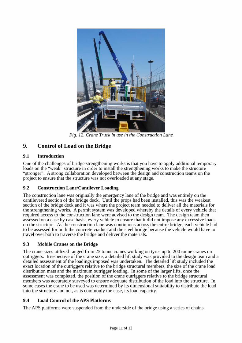
All materials for the APS platforms were delivered via the construction lane. With the New Jersey Barriers between the construction lane and the adjacent traffic lane, the useable width of the construction lane was limited to 2.4 metres. To install the public safety barrier posts without the need for additional lane closures, a lifting device was needed that would fit in this narrow lane. Although some small cranes could fit in the lane, their use was constrained either due to their high loading on the bridge deck or because the drive was tracked thereby making the speed of deployment too slow.
The solution devised was to use a small truck with a relatively large (10 tonne metre) hydraulic crane and winch. As such a vehicle is rare, and there were none readily available, the project opted to purchase the vehicle and the crane and have them customised to suit project requirements. Once delivered, this vehicle was so versatile that it was used around the clock on many more activities than had been originally planned.
Page 11 of 12
Fig. 12. Crane Truck in use in the Construction Lane
9. Control of Load on the Bridge
9.1 Introduction
One of the challenges of bridge strengthening works is that you have to apply additional temporary loads on the “weak” structure in order to install the strengthening works to make the structure “stronger”. A strong collaboration developed between the design and construction teams on the project to ensure that the structure was not overloaded at any stage.
9.2 Construction Lane/Cantilever Loading
The construction lane was originally the emergency lane of the bridge and was entirely on the cantilevered section of the bridge deck. Until the props had been installed, this was the weakest section of the bridge deck and it was where the project team needed to deliver all the materials for the strengthening works. A permit system was developed whereby the details of every vehicle that required access to the construction lane were advised to the design team. The design team then assessed on a case by case basis, every vehicle to ensure that it did not impose any excessive loads on the structure. As the construction lane was continuous across the entire bridge, each vehicle had to be assessed for both the concrete viaduct and the steel bridge because the vehicle would have to travel over both to traverse the bridge and deliver the materials.
9.3 Mobile Cranes on the Bridge
The crane sizes utilized ranged from 25 tonne cranes working on tyres up to 200 tonne cranes on outriggers. Irrespective of the crane size, a detailed lift study was provided to the design team and a detailed assessment of the loadings imposed was undertaken. The detailed lift study included the exact location of the outriggers relative to the bridge structural members, the size of the crane load distribution mats and the maximum outrigger loading. In some of the larger lifts, once the assessment was completed, the position of the crane outriggers relative to the bridge structural members was accurately surveyed to ensure adequate distribution of the load into the structure. In some cases the crane to be used was determined by its dimensional suitability to distribute the load into the structure and not, as is commonly the case, its load capacity.
9.4 Load Control of the APS Platforms
The APS platforms were suspended from the underside of the bridge using a series of chains

Page 12 of 12
connected to the bridge cantilevers. Since both the chains and cantilevers had a limited capacity, a strict load control regime was established for the platform. The weight of equipment on the platforms was known and storage areas were allocated and marked with the quantities allowed to be stored. The largest variable load was that of the personnel on the platforms and a set limit of the number of people per platform was established and assigned.
To control the number of people on the platform, a tag board was set up at the main access point to the platform on the bridge deck. This tag board carried the same number of tags as the number of people allowed on the platform. Each person accessing the platform collected a tag and carried it with them onto the platform where they attached it to a tag board on the platform. This procedure had the added benefit of emphasizing, in the minds of all using the platform, its limited capacity.
9.5 Global Loading on Bridge
Whilst the local loading issues were controlled as described above, the global loads on the bridge, particularly the steel bridge, also needed to be considered. When the project started, four existing maintenance gantries operated under the steel bridge and were only allowed to work within an established proximity of each other. These platforms were used during the course of the project to carry out the replacement and strengthening of bolted splices.
The internal strengthening of the bridge and the installation of the cantilever props and public safety barrier were also happening at the same time as the replacement and reinforcement of bolted splices. Each of these work fronts needed to be coordinated to ensure that the works did not interfere which each other and that the positioning of the platforms and gantries was not such as to overload the bridge.
Programming the construction work to avoid any interference between the work fronts is a normal part of construction work. With the four existing gantries, eight APS platforms and multiple internal work fronts, programming the work to take into account global loading of the bridge requires careful planning and control. Normally unrelated independent work fronts become constrained purely due to the global capacity limitations.
The global program was reviewed by the design team and agreed in principle for global load requirements. As the work progressed, to ensure that global loading issues did not interfere with the progress of the works, the program was presented using time-chainage format and this was provided to the design team. The design team analysed the work sequence to check that it did not globally overload the bridge; the outcome of the analysis was fed back to the construction team. This analysis and feedback process became a weekly iterative process where the teams met to review progress of the works and explore any changes to the sequence of the works. In this way the global loading of the bridge was controlled and never affected the progress of the works.
10. Outcomes of the Project After battling severe industrial relations problems at the start of the project, unforeseen latent conditions within the existing steel structure, extremely difficult occupational health and safety issues associated with the red lead coating inside the steel bridge and significant increases in material costs due to other difficulties encountered during the work, the 5th lane in both directions across West Gate Bridge was opened to traffic in June 2011, ahead of the sunset date written into the M1 Redevelopment Deed.
The three primary objectives of the strengthening project, detailed above, have been met.
West Gate Bridge has been strengthened to allow it to meet future demands of both commuter and freight traffic, and to do so in compliance with current day bridge loading and design standards. In particular, the traffic loading model used for the design had regard for the weight and mix of traffic currently using the bridge and VicRoads planning for the introduction of heavier High Productivity articulated vehicles.
Traffic capacity across the bridge has been increased by the opening of a 5th lane in each direction and the bridge is no longer a constraint on the traffic capacity of the M1.
Public and traffic safety across the bridge has been dramatically improved through the provision of suicide prevention barriers and the refurbishment and increased strength of the outer traffic barriers.