Embed Size (px)
Citation preview
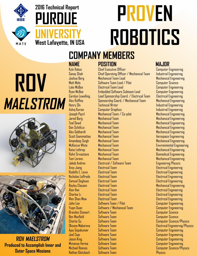
PROVEN ROBOTICSWest Lafayette, IN USA
2016 Technical Report
PURDUEUNIVERSITY
NAME POSITION MAJORKyle Rakos Chief Executive Officer Computer EngineeringSanay Shah Chief Operating Officer / Mechanical Team Industrial EngineeringJoshua Berg Mechanical Team Lead Mechanical EngineeringMatt Molo Software Team Lead / Pilot Computer ScienceLuke McBee Electrical Team Lead Computer EngineeringRyan McBee Embedded Software Subteam Lead Computer EngineeringCarolyn Lewelling Lead Sponsorship Coord. / Electrical Team Electrical EngineeringAlex Ruffino Sponsorship Coord. / Mechanical Team Mechanical EngineeringHenry Shi Technical Writer Industrial EngineeringAshiq Kurian Computer Graphics Industrial EngineeringJoseph Pejril Mechanical Team / Co-pilot Mechanical EngineeringJared Borg Mechanical Team Mechanical EngineeringTeal Dowd Mechanical Team Mechanical EngineeringDan Schillizzi Mechanical Team Mechanical EngineeringAlex Gebhardt Mechanical Team Mechanical EngineeringScott Giammatteo Mechanical Team Aerospace EngineeringAmandeep Singh Mechanical Team Mechanical EngineeringMcKenzie White Mechanical Team Environmental EngineeringKatie Lothrop Mechanical Team Mechanical EngineeringRohit Srivastava Mechanical Team Biomedical EngineeringTom Lorenc Mechanical Team Mechanical EngineeringJakob Andren Electrical / Software Team Engineering PhysicsXinyi Jiang Electrical Team Electrical EngineeringRodolfo E. Leiva Electrical Team Electrical EngineeringNicholas Loffredo Electrical Team Electrical EngineeringSamuel Deghuee Electrical Team Electrical EngineeringBayley Clausen Electrical Team Mechanical EngineeringAlan Han Electrical Team Electrical EngineeringCharles Li Electrical Team Electrical EngineeringWen Shen Mow Electrical Team Electrical EngineeringJohn Lee Software Team / Pilot Computer EngineeringYuqin Duan Software / Mechanical Team Computer EngineeringBrandon Stewart Software Team Computer ScienceBen Maxfield Software Team Computer ScienceCharlie Su Software Team Computer Science/PhysicsOksana Makarova Software Team Electrical Engineering/PhysicsAjay Gopakumar Software Team Computer EngineeringJoel Copi Software Team Computer EngineeringJason King Software Team Computer EngineeringMimansa Verma Software Team Computer EngineeringMichael Reeves Software Team Computer Science/PhysicsNathan Glotzbach Software Team Physics
ROV MAELSTROM
COMPANY MEMBERS
ROV MAELSTROMProduced to Accomplish Inner and
Outer Space Missions
Proven Robotics
2
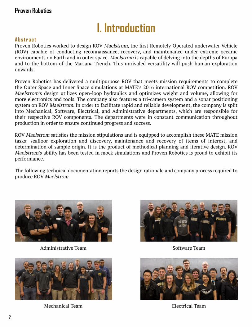
Abstrac tProven Robotics worked to design ROV Maelstrom, the first Remotely Operated underwater Vehicle (ROV) capable of conducting reconnaissance, recovery, and maintenance under extreme oceanic environments on Earth and in outer space. Maelstrom is capable of delving into the depths of Europa and to the bottom of the Mariana Trench. This unrivaled versatility will push human exploration onwards. Proven Robotics has delivered a multipurpose ROV that meets mission requirements to complete the Outer Space and Inner Space simulations at MATE’s 2016 international ROV competition. ROV Maelstrom’s design utilizes open-loop hydraulics and optimizes weight and volume, allowing for more electronics and tools. The company also features a tri-camera system and a sonar positioning system on ROV Maelstrom. In order to facilitate rapid and reliable development, the company is split into Mechanical, Software, Electrical, and Administrative departments, which are responsible for their respective ROV components. The departments were in constant communication throughout production in order to ensure continued progress and success.
ROV Maelstrom satisfies the mission stipulations and is equipped to accomplish these MATE mission tasks: seafloor exploration and discovery, maintenance and recovery of items of interest, and determination of sample origin. It is the product of methodical planning and iterative design. ROV Maelstrom’s ability has been tested in mock simulations and Proven Robotics is proud to exhibit its performance.
The following technical documentation reports the design rationale and company process required to produce ROV Maelstrom.
Administrative Team
Mechanical Team
Software Team
Electrical Team
I. Introduction
3
ROV Maelstrom Technical Report
Tab le o f Conten tsI. Introduction 2
Abstract 2Table of Contents 3
II. Safety 4A. Safety Philosophy 4B. Safety Standards 4C. Safety Features 4
III. Mechanical Design Rationale 5Mechanical Overview 5A. Frame 5B. Power Distribution Box 5C. Electronics Tube 6D. Main Camera Housing and Tilt Mechanism 6E. Secondary Camera Housings 7F. Buoyancy 7G. Open-Loop Hydraulics 7Mission Tools 8A. Main Manipulator 8B. Environmental Sample Processor (ESP) Manipulator 9C. Wellhead Tool 9D. Temperature Sensor 9
IV. Electrical Design Rationale 10Electronics Overview 10A. Power Distribution Board 10B. Blue Robotics T200 Thrusters 11C. Backplane 11D. Power Regulator Board 12E. Main Microcontroller Board 12F. Application Board 12G. Navigation Board 13H. Sonar Receiver Board 13
V. Software Design Rationale 14Software Overview 14A. BattleStation 14B. Camera View Application 14C. Movement Control 15D. Tether Communications 15E. CAN Bus Communication 15
VI. Logistics 16A. Company Organization 16C. Project Management 16D. Project Costing and Budget 16
VII. Conclusion 18A. Challenges 18B. Lessons Learned and Skills Gained 18C. Future Improvements 18D. Reflections 18
VIII. Appendix 20A. Safety Checklist 21B. System Interconnect Diagrams 22C. Acknowledgments 24D. References 25
Proven Robotics
4
Fig. 1 - Having fun while working towards ROV Maelstrom
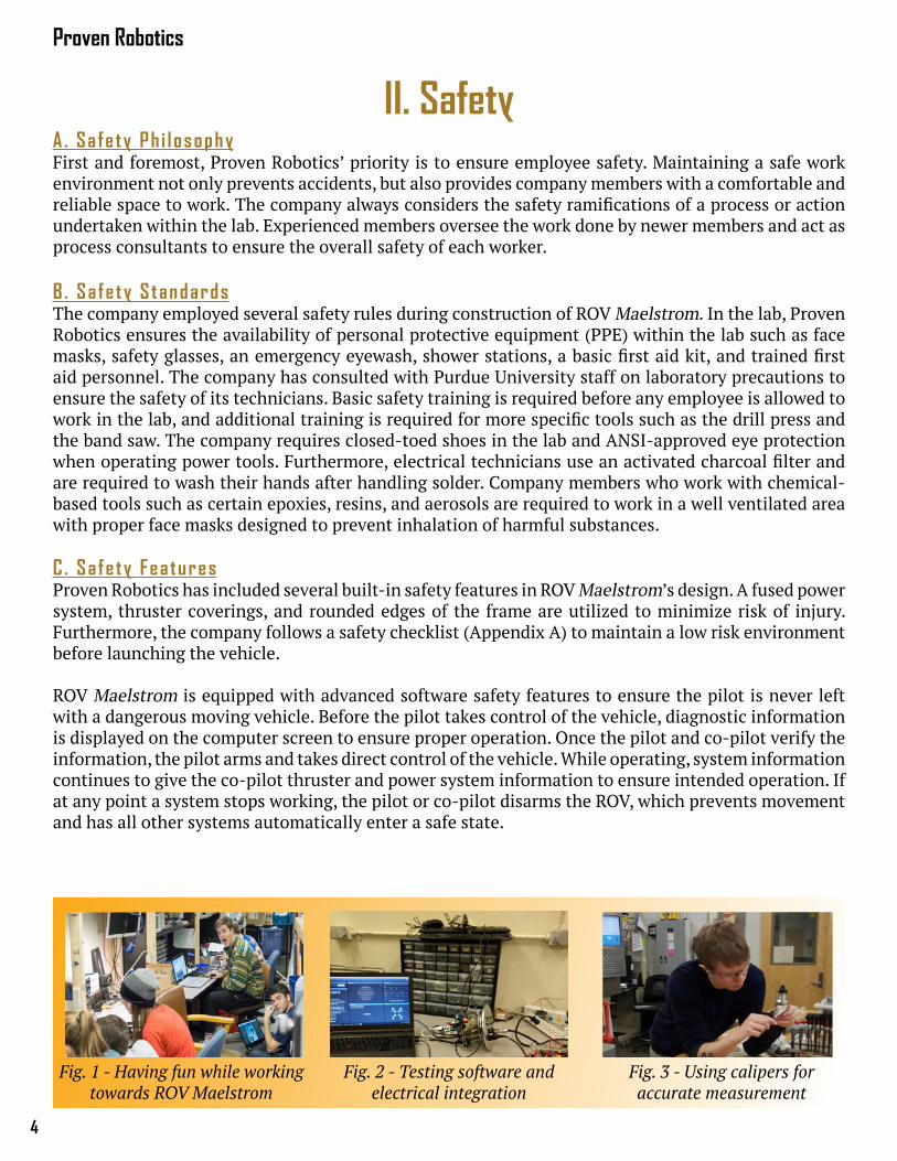
II. SafetyA. Sa fe ty Ph i l osophyFirst and foremost, Proven Robotics’ priority is to ensure employee safety. Maintaining a safe work environment not only prevents accidents, but also provides company members with a comfortable and reliable space to work. The company always considers the safety ramifications of a process or action undertaken within the lab. Experienced members oversee the work done by newer members and act as process consultants to ensure the overall safety of each worker.
B . Sa fe ty S tandardsThe company employed several safety rules during construction of ROV Maelstrom. In the lab, Proven Robotics ensures the availability of personal protective equipment (PPE) within the lab such as face masks, safety glasses, an emergency eyewash, shower stations, a basic first aid kit, and trained first aid personnel. The company has consulted with Purdue University staff on laboratory precautions to ensure the safety of its technicians. Basic safety training is required before any employee is allowed to work in the lab, and additional training is required for more specific tools such as the drill press and the band saw. The company requires closed-toed shoes in the lab and ANSI-approved eye protection when operating power tools. Furthermore, electrical technicians use an activated charcoal filter and are required to wash their hands after handling solder. Company members who work with chemical-based tools such as certain epoxies, resins, and aerosols are required to work in a well ventilated area with proper face masks designed to prevent inhalation of harmful substances.
C . Sa fe ty Fea turesProven Robotics has included several built-in safety features in ROV Maelstrom’s design. A fused power system, thruster coverings, and rounded edges of the frame are utilized to minimize risk of injury. Furthermore, the company follows a safety checklist (Appendix A) to maintain a low risk environment before launching the vehicle.
ROV Maelstrom is equipped with advanced software safety features to ensure the pilot is never left with a dangerous moving vehicle. Before the pilot takes control of the vehicle, diagnostic information is displayed on the computer screen to ensure proper operation. Once the pilot and co-pilot verify the information, the pilot arms and takes direct control of the vehicle. While operating, system information continues to give the co-pilot thruster and power system information to ensure intended operation. If at any point a system stops working, the pilot or co-pilot disarms the ROV, which prevents movement and has all other systems automatically enter a safe state.
Fig. 2 - Testing software and electrical integration
Fig. 3 - Using calipers for accurate measurement
5
ROV Maelstrom Technical Report
III. Mechanical Design RationaleMechan ica l Overv iewAll mechanical aspects of ROV Maelstrom were thoroughly discussed before designs were finalized. Following the internal review process among the technical departments, all designs were converted to SolidWorks drawings. Stress analysis and simulation data were used to fine-tune the CAD models. Prototypes were then tested under conditions similar to the mission's, which provided knowledge to fine tune the final mechanical features to satisfy mission needs.
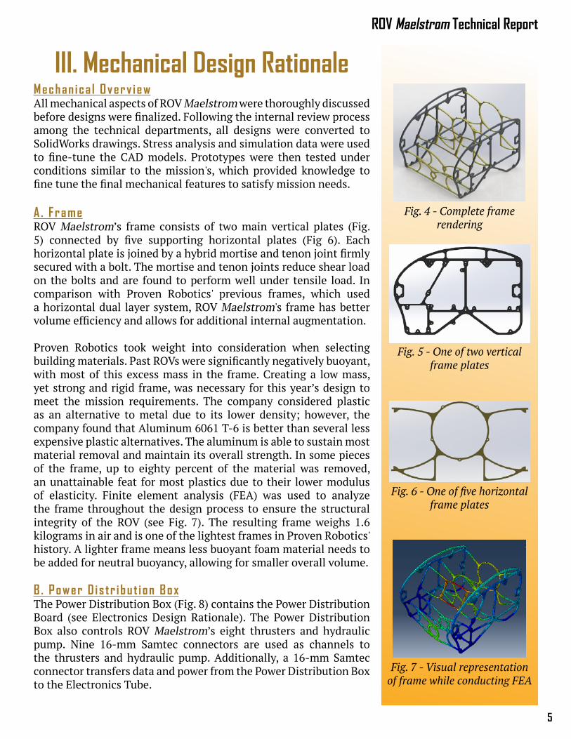
A . FrameROV Maelstrom’s frame consists of two main vertical plates (Fig. 5) connected by five supporting horizontal plates (Fig 6). Each horizontal plate is joined by a hybrid mortise and tenon joint firmly secured with a bolt. The mortise and tenon joints reduce shear load on the bolts and are found to perform well under tensile load. In comparison with Proven Robotics' previous frames, which used a horizontal dual layer system, ROV Maelstrom's frame has better volume efficiency and allows for additional internal augmentation.
Proven Robotics took weight into consideration when selecting building materials. Past ROVs were significantly negatively buoyant, with most of this excess mass in the frame. Creating a low mass, yet strong and rigid frame, was necessary for this year’s design to meet the mission requirements. The company considered plastic as an alternative to metal due to its lower density; however, the company found that Aluminum 6061 T-6 is better than several less expensive plastic alternatives. The aluminum is able to sustain most material removal and maintain its overall strength. In some pieces of the frame, up to eighty percent of the material was removed, an unattainable feat for most plastics due to their lower modulus of elasticity. Finite element analysis (FEA) was used to analyze the frame throughout the design process to ensure the structural integrity of the ROV (see Fig. 7). The resulting frame weighs 1.6 kilograms in air and is one of the lightest frames in Proven Robotics' history. A lighter frame means less buoyant foam material needs to be added for neutral buoyancy, allowing for smaller overall volume.
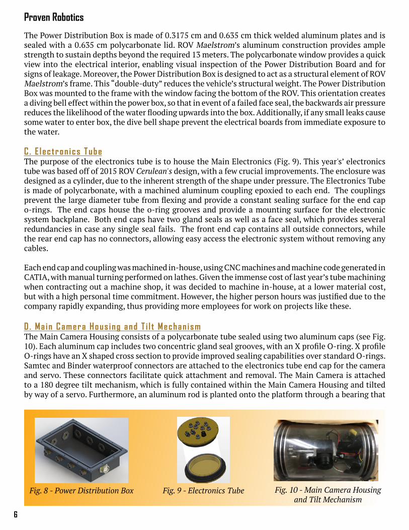
B . Power D is tr ibu t i on BoxThe Power Distribution Box (Fig. 8) contains the Power Distribution Board (see Electronics Design Rationale). The Power Distribution Box also controls ROV Maelstrom’s eight thrusters and hydraulic pump. Nine 16-mm Samtec connectors are used as channels to the thrusters and hydraulic pump. Additionally, a 16-mm Samtec connector transfers data and power from the Power Distribution Box to the Electronics Tube.
Fig. 5 - One of two vertical frame plates
Fig. 6 - One of five horizontal frame plates
Fig. 7 - Visual representation of frame while conducting FEA
Fig. 4 - Complete frame rendering
Proven Robotics
6
The Power Distribution Box is made of 0.3175 cm and 0.635 cm thick welded aluminum plates and is sealed with a 0.635 cm polycarbonate lid. ROV Maelstrom’s aluminum construction provides ample strength to sustain depths beyond the required 13 meters. The polycarbonate window provides a quick view into the electrical interior, enabling visual inspection of the Power Distribution Board and for signs of leakage. Moreover, the Power Distribution Box is designed to act as a structural element of ROV Maelstrom’s frame. This “double-duty” reduces the vehicle’s structural weight. The Power Distribution Box was mounted to the frame with the window facing the bottom of the ROV. This orientation creates a diving bell effect within the power box, so that in event of a failed face seal, the backwards air pressure reduces the likelihood of the water flooding upwards into the box. Additionally, if any small leaks cause some water to enter box, the dive bell shape prevent the electrical boards from immediate exposure to the water.
C . E l ec tron ics TubeThe purpose of the electronics tube is to house the Main Electronics (Fig. 9). This year's’ electronics tube was based off of 2015 ROV Cerulean's design, with a few crucial improvements. The enclosure was designed as a cylinder, due to the inherent strength of the shape under pressure. The Electronics Tube is made of polycarbonate, with a machined aluminum coupling epoxied to each end. The couplings prevent the large diameter tube from flexing and provide a constant sealing surface for the end cap o-rings. The end caps house the o-ring grooves and provide a mounting surface for the electronic system backplane. Both end caps have two gland seals as well as a face seal, which provides several redundancies in case any single seal fails. The front end cap contains all outside connectors, while the rear end cap has no connectors, allowing easy access the electronic system without removing any cables.
Each end cap and coupling was machined in-house, using CNC machines and machine code generated in CATIA, with manual turning performed on lathes. Given the immense cost of last year’s tube machining when contracting out a machine shop, it was decided to machine in-house, at a lower material cost, but with a high personal time commitment. However, the higher person hours was justified due to the company rapidly expanding, thus providing more employees for work on projects like these.
D . Ma in Camera Hous ing and T i l t Mechan ismThe Main Camera Housing consists of a polycarbonate tube sealed using two aluminum caps (see Fig. 10). Each aluminum cap includes two concentric gland seal grooves, with an X profile O-ring. X profile O-rings have an X shaped cross section to provide improved sealing capabilities over standard O-rings. Samtec and Binder waterproof connectors are attached to the electronics tube end cap for the camera and servo. These connectors facilitate quick attachment and removal. The Main Camera is attached to a 180 degree tilt mechanism, which is fully contained within the Main Camera Housing and tilted by way of a servo. Furthermore, an aluminum rod is planted onto the platform through a bearing that
Fig. 8 - Power Distribution Box Fig. 9 - Electronics Tube Fig. 10 - Main Camera Housing and Tilt Mechanism
7
ROV Maelstrom Technical Report
supports the weight of the camera to keep it aligned. To avoid image warping as the camera rotates up and down, it was specifically located to be on the central axis of the polycarbonate tube.The design of this mechanism is a response to last year’s camera box and its shortcomings. The previous design consisted of a two-axis gimbaled system that was actuated by two stepper motors housed outside the camera housing. The design included dynamic seals that proved unreliable. Consequently, the company opted for a single servo that contains all actuation inside the housing. This allows for using static seals and simplifies electrical requirements for tilting the camera.
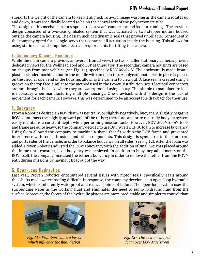
E . Secondary Camera Hous ingsWhile the main camera provides an overall frontal view, the two smaller stationary cameras provide dedicated views for the Wellhead Tool and ESP Manipulator. The secondary camera housings are based on designs from past vehicles (see Fig. 11), specifically ROV Model N. The enclosure is made from a plastic cylinder machined out in the middle with an open top. A polycarbonate plastic piece is placed on the circular open end of the housing, allowing the camera to view out. A face seal is created using a groove on the top face, similar to the method used in the Power Distribution Box. Electrical connectors are run through the back, where they are waterproofed using epoxy. This simple to manufacture idea is necessary when manufacturing multiple housings. One drawback with this design is the lack of movement for each camera. However, this was determined to be an acceptable drawback for their use.
F . BuoyancyProven Robotics desired an ROV that was neutrally, or slightly negatively, buoyant. A slightly negative ROV counteracts the slightly upward pull of the tether; therefore, an entire neutrally buoyant system easily maintains a constant depth while performing mission tasks. However, ROV Maelstrom’s tools and frame are quite heavy, so the company decided to use Divinycell HCP 30 foam to increase buoyancy. Using foam allowed the company to machine a shape that fit within the ROV frame and prevented interference with tools, thrusters and other components. This design is symmetric to the starboard and ports sides of the vehicle, in order to balance buoyancy on all sides (see Fig 12). After the foam was added, Proven Robotics adjusted the ROV’s buoyancy with the addition of small weights placed around the frame until constant, level buoyancy was achieved. In addition to buoyancy adjustments on the ROV itself, the company increased the tether’s buoyancy in order to remove the tether from the ROV’s path during missions by having it float out of the way. G . Open-Loop Hydrau l i csLast year, Proven Robotics encountered several issues with motor seals; specifically, seals around the shafts made waterproofing difficult. In response, the company developed an open-loop hydraulic system, which is inherently waterproof and reduces points of failure. The open-loop system uses the surrounding water as the working fluid and eliminates the need to pump hydraulic fluid from the surface. Moreover, the forces of the hydraulic pistons are more predictable and simpler to control than
Fig. 11 - Prototype camera boxes which influence the final design
Fig. 12 - The custom shaped foam over ROV Maelstrom
Proven Robotics
8
a motor’s, since only basic opening and closing actions were needed. Water is also nearly incompressible and, given an input pumping pressure, provided the system with a consistent force value.To pressurize water, a Blue Robotics M100 brushless DC motor is coupled with a 24-V diaphragm pump for a high pressure output. The pump’s output is routed through a solenoid bank and directs water to the pistons for firing and releasing. The solenoid bank is encased in a plastic open top container and was potted with “Magic Gel”, a bicomponent gel used in industry to waterproof electronics. The design made installing the solenoid banks to the container easier with minimal risk of leakage. The hydraulic system powered the actuators for the Main Manipulator and Wellhead Tool. A fluid diagram of the system can be found in Appendix B.
Miss ion Too lsTo attack each challenge, Proven Robotics devised a set of Mission Tools to quickly and efficiently accomplish each mission tasks. For task one, the Temperature Sensor measures the venting fluid, and the ESP Manipulator is used to work with the ESP cable connector. The Main Manipulator is used for the remaining tasks to position and transport equipment, collect oil and coral samples, and install the wellhead flange and cap. For the fifth task, the additional Wellhead Tool secures both the wellhead flange and cap.
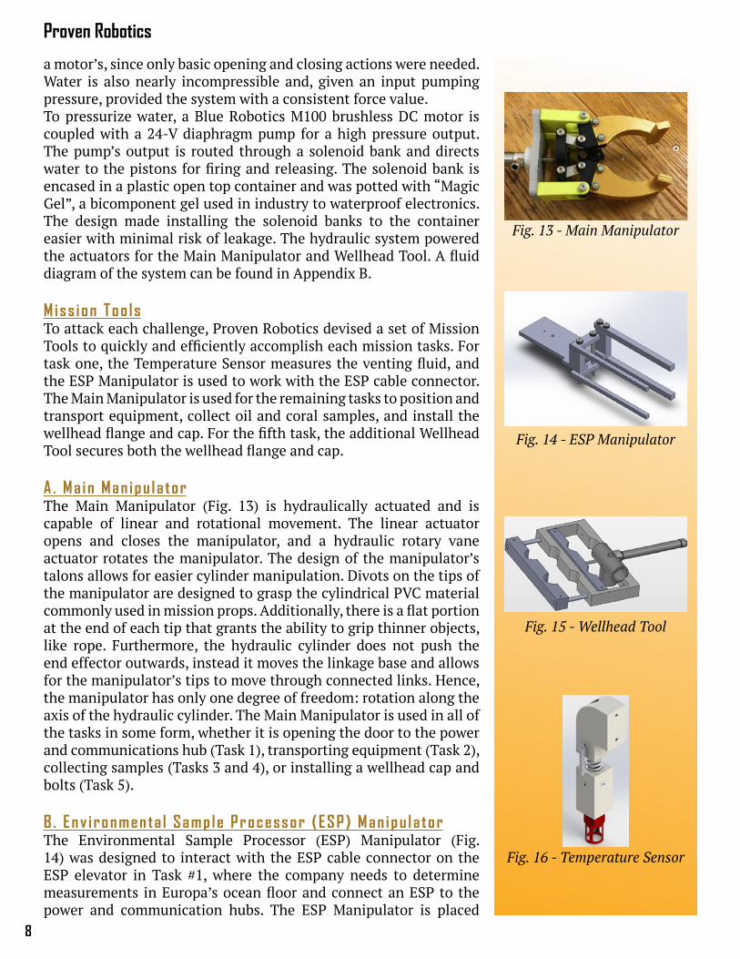
A . Ma in Man ipu la torThe Main Manipulator (Fig. 13) is hydraulically actuated and is capable of linear and rotational movement. The linear actuator opens and closes the manipulator, and a hydraulic rotary vane actuator rotates the manipulator. The design of the manipulator’s talons allows for easier cylinder manipulation. Divots on the tips of the manipulator are designed to grasp the cylindrical PVC material commonly used in mission props. Additionally, there is a flat portion at the end of each tip that grants the ability to grip thinner objects, like rope. Furthermore, the hydraulic cylinder does not push the end effector outwards, instead it moves the linkage base and allows for the manipulator’s tips to move through connected links. Hence, the manipulator has only one degree of freedom: rotation along the axis of the hydraulic cylinder. The Main Manipulator is used in all of the tasks in some form, whether it is opening the door to the power and communications hub (Task 1), transporting equipment (Task 2), collecting samples (Tasks 3 and 4), or installing a wellhead cap and bolts (Task 5).
B . Env i ronmenta l Samp le Processor (ESP) Man ipu la torThe Environmental Sample Processor (ESP) Manipulator (Fig. 14) was designed to interact with the ESP cable connector on the ESP elevator in Task #1, where the company needs to determine measurements in Europa’s ocean floor and connect an ESP to the power and communication hubs. The ESP Manipulator is placed
Fig. 14 - ESP Manipulator
Fig. 15 - Wellhead Tool
Fig. 16 - Temperature Sensor
Fig. 13 - Main Manipulator
9
ROV Maelstrom Technical Report
on the right of the Main Manipulator to avoid positioning problems between the ROV and the cable connector while conducting missions.
The ESP Manipulator consists of a stationary side with two straight fingers, and a mobile side with two L-shaped arms that act as grippers. The mobile side is actuated using a hydraulic cylinder that is attached on the Main Manipulator’s base plate. This positioning for the hydraulic cylinder allows the ESP Manipulator to be placed on the lower frame; preventing the ESP Manipulator from protruding from the ROV and lowering damage risks.
The ESP manipulator exerts its maximum torque when the ESP cable connector is in its grasp; this design lowers the risk of dropping item. The company had originally considered a system in which both sides of the claw could be moved; however, the company decided against this system because there was a smaller chance for the single-side design to fail. Furthermore, the single-side design is more pragmatic because it shrank the overall plate size.
C . We l l head Too lThe 5th task requests the attachment of a flange to the top of a decommissioned wellhead and the installment of a wellhead cap to the top of the flange. Performing the wellhead task requires a series of smaller sub-tasks that must be performed in a specific order. In order to aid in the ease of some of the more repetitive tasks, such as the installation of bolts on the wellhead, the Wellhead Tool (Fig. 15) was designed to place all four bolts on in a single pass. The bolts are brought to the Control Center by the ROV, and are collected by a company member for positioning. The clamping blocks have grooves to keep each bolt in position. The Wellhead Tool clamps the bolts into a position where all the bolts can be inserted in a single step. This tool is controlled by hydraulics, therefore only allowing for two possible positions: fully open and fully closed. Due to the design, the following steps are done manually by company members: the company must place all top bolts into position within the Wellhead Tool, close the tool, and position it over the wellhead. Once in position over the wellhead, the ROV maneuvers down, placing the bolts into their corresponding holes. After the bolts are placed in the holes, the tool opens up and releases the bolts.
D . Temperature SensorThe Temperature Sensor (Fig. 16) was designed to make positioning ROV Maelstrom during thermal readings an effortless task. The sensory tool is positioned on the left side of the ROV at an open space to avoid tool blockage during other mission tasks. The sensor is connected to ROV Maelstrom via a spring coupling system, composed of two blocks, four extension springs, and two compression springs. The spring coupling system allows the Temperature Sensor to deflect upon impact; this feature facilitates easy alignment and helps ensure the Temperature Sensor is guided into the vent.
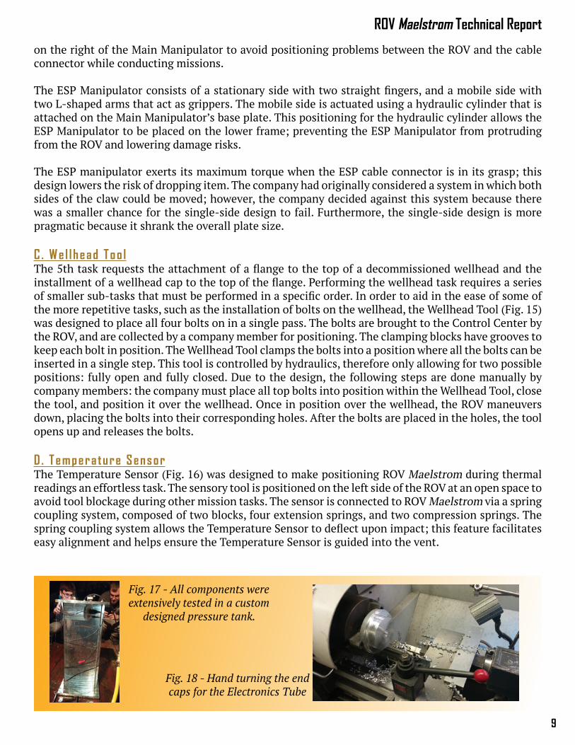
Fig. 18 - Hand turning the end caps for the Electronics Tube
Fig. 17 - All components were extensively tested in a custom
designed pressure tank.
Proven Robotics
10
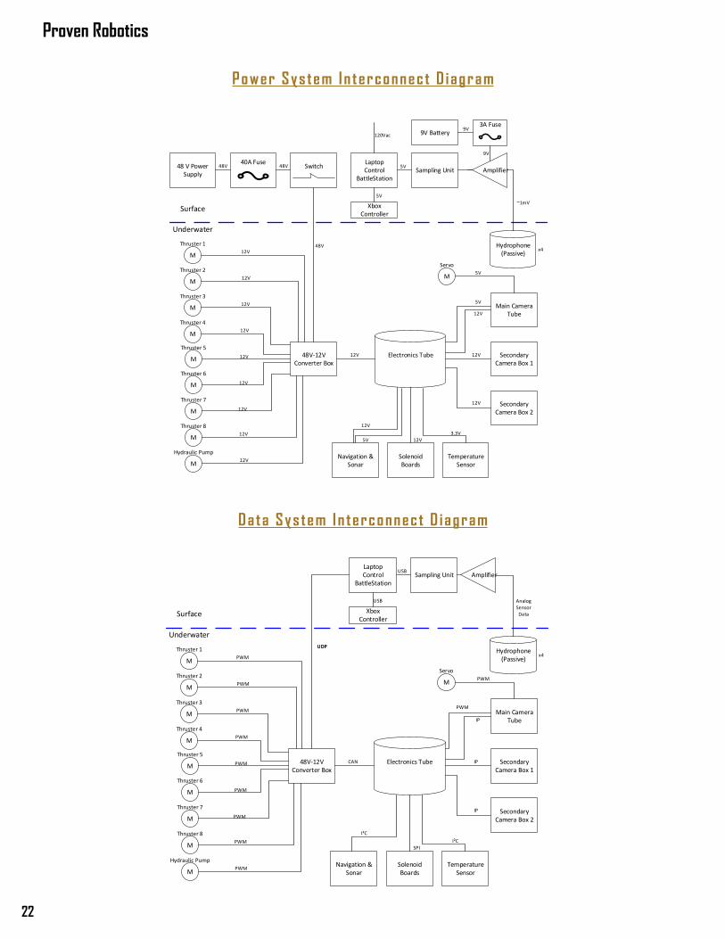
IV. Electrical Design RationaleElectron ics Overv iewROV Maelstrom’s electronics were designed to facilitate easy and reliable command over the course of the ROV’s lifetime. Command starts at the Control Center, the surface electronics that the user interfaces with. This includes a laptop computer, a network router, and a 48 V power supply protected with a 40-A fuse.
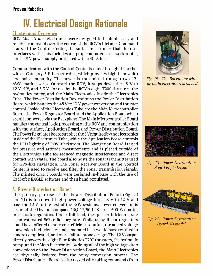
Communication with the Control Center is done through the tether with a Category 5 Ethernet cable, which provides high bandwidth and noise immunity. The power is transmitted through two 12-AWG marine wires. Onboard the ROV, it steps down the 48 V to 12 V, 5 V, and 3.3 V for use by the ROV’s eight T200 thrusters, the hydraulics motor, and the Main Electronics inside the Electronics Tube. The Power Distribution Box contains the Power Distribution Board, which handles the 48 V to 12 V power conversion and thruster control. Inside of the Electronics Tube are the Main Microcontroller Board, the Power Regulator Board, and the Application Board which are all connected via the Backplane. The Main Microcontroller Board handles the central logic processing of the ROV and communication with the surface, Application Board, and Power Distribution Board. The Power Regulator Board supplies the 5 V required by the electronics inside of the Electronics Tube, while the Application Board controls the LED lighting of ROV Maelstrom. The Navigation Board is used for pressure and attitude measurements and is placed outside of the Electronics Tube for reduced magnetic interference and direct contact with water. The board also hosts the sonar transmitter used for GPS-like navigation. The Sonar Receiver Board in the Control Center is used to receive and filter the sonar transmission signals. The printed circuit boards were designed in-house with the use of CadSoft's EAGLE software and then hand populated.
A . Power D is tr ibu t i on BoardThe primary purpose of the Power Distribution Board (Fig. 20 and 21) is to convert high power voltage from 48 V to 12 V and pass the 12 V to the rest of the ROV systems. Power conversion is accomplished by four compact DRQ-12/50-L48 series 600-W quarter brick buck regulators. Under full load, the quarter-bricks operate at an estimated 96% efficiency rate. While using linear regulators could have offered a more cost efficient solution, the added voltage conversion inefficiencies and generated heat would have resulted in a more complicated, and more failure prone design. The 12 V output directly powers the eight Blue Robotics T200 thrusters, the hydraulic pump, and the Main Electronics. By doing all of the high voltage drop conversions on the Power Distribution Board, the Main Electronics are physically isolated from the noisy conversion process. The Power Distribution Board is also tasked with taking commands from
Fig. 20 - Power Distribution Board Eagle Layout
Fig. 21 - Power Distribution Board 3D model
Fig. 19 - The Backplane with the main electronics attached
11
ROV Maelstrom Technical Report
the Main Microcontroller over the CAN bus and translating those commands into outputs for the thrusters. This is done through an I2C-to-PWM integrated circuit, which takes commands over I2C and outputs the 8 different PWM (Pulse-Width-Modulation) channels required to allow for discrete command of each thruster. While I2C was originally intended to control the thrusters, back voltage left the original Electronic Speed Controllers (ESCs) inoperable. This lead the company to use PWM controlled ESCs. The I2C-to-PWM chip was added to produce PWM signals without taking up the majority of the dedicated PWM pins on the microcontroller.
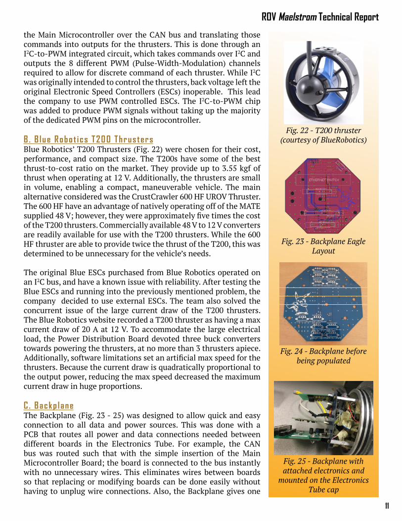
B . B lue Robot i cs T200 Thrus tersBlue Robotics’ T200 Thrusters (Fig. 22) were chosen for their cost, performance, and compact size. The T200s have some of the best thrust-to-cost ratio on the market. They provide up to 3.55 kgf of thrust when operating at 12 V. Additionally, the thrusters are small in volume, enabling a compact, maneuverable vehicle. The main alternative considered was the CrustCrawler 600 HF UROV Thruster. The 600 HF have an advantage of natively operating off of the MATE supplied 48 V; however, they were approximately five times the cost of the T200 thrusters. Commercially available 48 V to 12 V converters are readily available for use with the T200 thrusters. While the 600 HF thruster are able to provide twice the thrust of the T200, this was determined to be unnecessary for the vehicle’s needs.
The original Blue ESCs purchased from Blue Robotics operated on an I2C bus, and have a known issue with reliability. After testing the Blue ESCs and running into the previously mentioned problem, the company decided to use external ESCs. The team also solved the concurrent issue of the large current draw of the T200 thrusters. The Blue Robotics website recorded a T200 thruster as having a max current draw of 20 A at 12 V. To accommodate the large electrical load, the Power Distribution Board devoted three buck converters towards powering the thrusters, at no more than 3 thrusters apiece. Additionally, software limitations set an artificial max speed for the thrusters. Because the current draw is quadratically proportional to the output power, reducing the max speed decreased the maximum current draw in huge proportions.
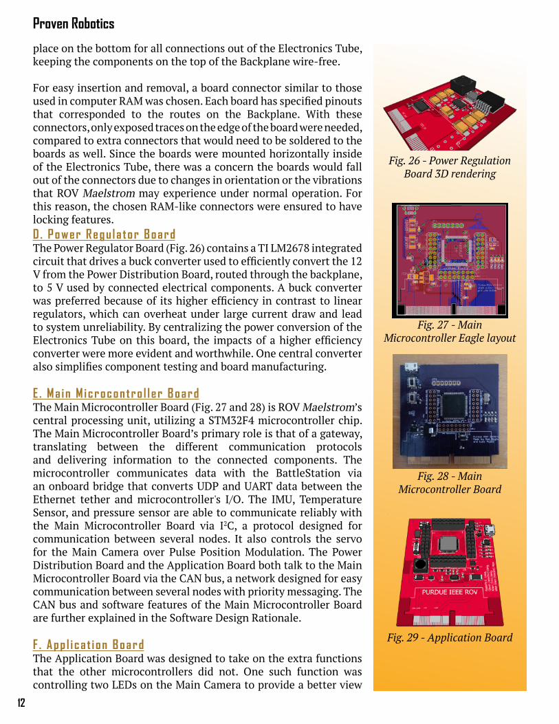
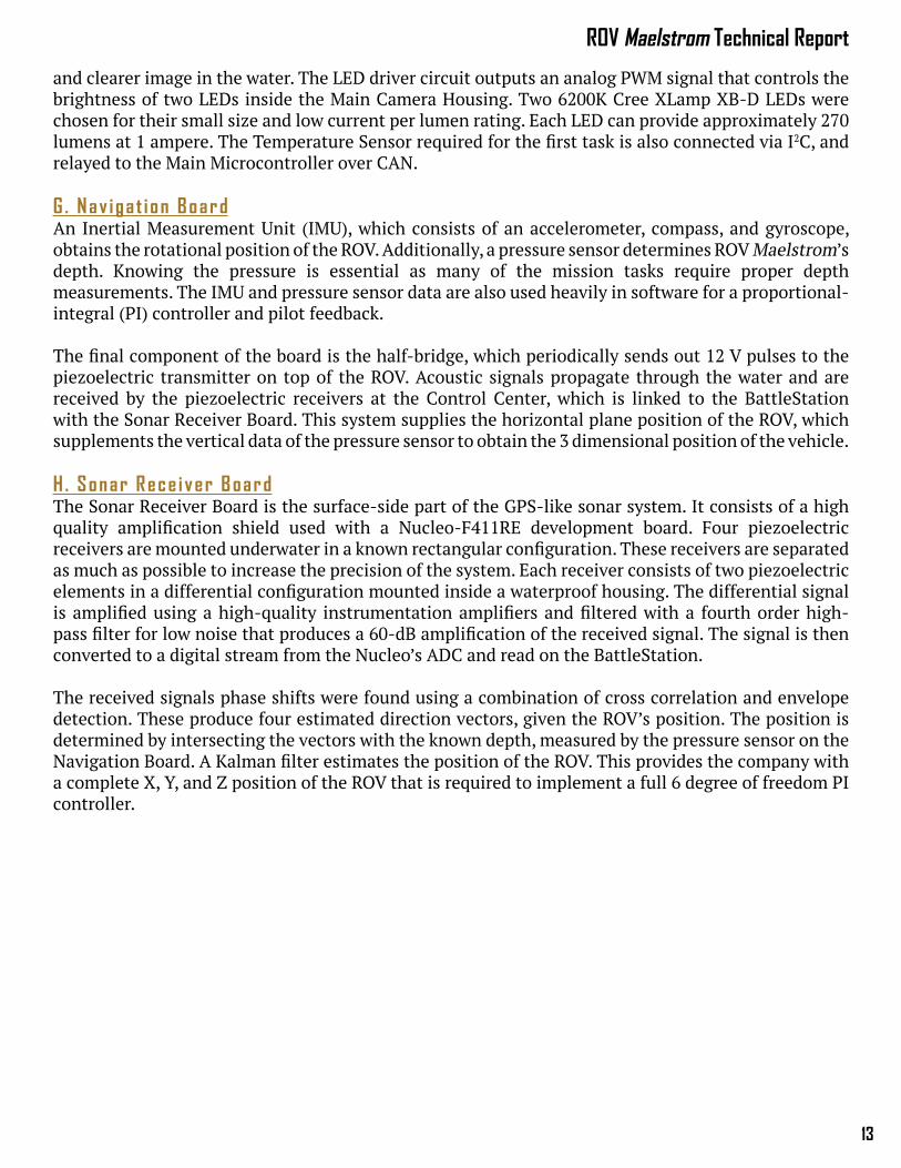
C . Backp laneThe Backplane (Fig. 23 - 25) was designed to allow quick and easy connection to all data and power sources. This was done with a PCB that routes all power and data connections needed between different boards in the Electronics Tube. For example, the CAN bus was routed such that with the simple insertion of the Main Microcontroller Board; the board is connected to the bus instantly with no unnecessary wires. This eliminates wires between boards so that replacing or modifying boards can be done easily without having to unplug wire connections. Also, the Backplane gives one
Fig. 23 - Backplane Eagle Layout
Fig. 24 - Backplane before being populated
Fig. 25 - Backplane with attached electronics and
mounted on the Electronics Tube cap
Fig. 22 - T200 thruster (courtesy of BlueRobotics)
Proven Robotics
12
place on the bottom for all connections out of the Electronics Tube, keeping the components on the top of the Backplane wire-free.
For easy insertion and removal, a board connector similar to those used in computer RAM was chosen. Each board has specified pinouts that corresponded to the routes on the Backplane. With these connectors, only exposed traces on the edge of the board were needed, compared to extra connectors that would need to be soldered to the boards as well. Since the boards were mounted horizontally inside of the Electronics Tube, there was a concern the boards would fall out of the connectors due to changes in orientation or the vibrations that ROV Maelstrom may experience under normal operation. For this reason, the chosen RAM-like connectors were ensured to have locking features.D . Power Regu la tor BoardThe Power Regulator Board (Fig. 26) contains a TI LM2678 integrated circuit that drives a buck converter used to efficiently convert the 12 V from the Power Distribution Board, routed through the backplane, to 5 V used by connected electrical components. A buck converter was preferred because of its higher efficiency in contrast to linear regulators, which can overheat under large current draw and lead to system unreliability. By centralizing the power conversion of the Electronics Tube on this board, the impacts of a higher efficiency converter were more evident and worthwhile. One central converter also simplifies component testing and board manufacturing.
E . Ma in M icrocontro l l er BoardThe Main Microcontroller Board (Fig. 27 and 28) is ROV Maelstrom’s central processing unit, utilizing a STM32F4 microcontroller chip. The Main Microcontroller Board’s primary role is that of a gateway, translating between the different communication protocols and delivering information to the connected components. The microcontroller communicates data with the BattleStation via an onboard bridge that converts UDP and UART data between the Ethernet tether and microcontroller's I/O. The IMU, Temperature Sensor, and pressure sensor are able to communicate reliably with the Main Microcontroller Board via I2C, a protocol designed for communication between several nodes. It also controls the servo for the Main Camera over Pulse Position Modulation. The Power Distribution Board and the Application Board both talk to the Main Microcontroller Board via the CAN bus, a network designed for easy communication between several nodes with priority messaging. The CAN bus and software features of the Main Microcontroller Board are further explained in the Software Design Rationale.
F . App l i ca t i on BoardThe Application Board was designed to take on the extra functions that the other microcontrollers did not. One such function was controlling two LEDs on the Main Camera to provide a better view
Fig. 27 - Main Microcontroller Eagle layout
Fig. 28 - Main Microcontroller Board
Fig. 29 - Application Board
Fig. 26 - Power Regulation Board 3D rendering
13
ROV Maelstrom Technical Report
and clearer image in the water. The LED driver circuit outputs an analog PWM signal that controls the brightness of two LEDs inside the Main Camera Housing. Two 6200K Cree XLamp XB-D LEDs were chosen for their small size and low current per lumen rating. Each LED can provide approximately 270 lumens at 1 ampere. The Temperature Sensor required for the first task is also connected via I2C, and relayed to the Main Microcontroller over CAN.
G . Nav iga t i on BoardAn Inertial Measurement Unit (IMU), which consists of an accelerometer, compass, and gyroscope, obtains the rotational position of the ROV. Additionally, a pressure sensor determines ROV Maelstrom’s depth. Knowing the pressure is essential as many of the mission tasks require proper depth measurements. The IMU and pressure sensor data are also used heavily in software for a proportional-integral (PI) controller and pilot feedback.
The final component of the board is the half-bridge, which periodically sends out 12 V pulses to the piezoelectric transmitter on top of the ROV. Acoustic signals propagate through the water and are received by the piezoelectric receivers at the Control Center, which is linked to the BattleStation with the Sonar Receiver Board. This system supplies the horizontal plane position of the ROV, which supplements the vertical data of the pressure sensor to obtain the 3 dimensional position of the vehicle.
H . Sonar Rece iver BoardThe Sonar Receiver Board is the surface-side part of the GPS-like sonar system. It consists of a high quality amplification shield used with a Nucleo-F411RE development board. Four piezoelectric receivers are mounted underwater in a known rectangular configuration. These receivers are separated as much as possible to increase the precision of the system. Each receiver consists of two piezoelectric elements in a differential configuration mounted inside a waterproof housing. The differential signal is amplified using a high-quality instrumentation amplifiers and filtered with a fourth order high-pass filter for low noise that produces a 60-dB amplification of the received signal. The signal is then converted to a digital stream from the Nucleo’s ADC and read on the BattleStation.
The received signals phase shifts were found using a combination of cross correlation and envelope detection. These produce four estimated direction vectors, given the ROV’s position. The position is determined by intersecting the vectors with the known depth, measured by the pressure sensor on the Navigation Board. A Kalman filter estimates the position of the ROV. This provides the company with a complete X, Y, and Z position of the ROV that is required to implement a full 6 degree of freedom PI controller.
Proven Robotics
14
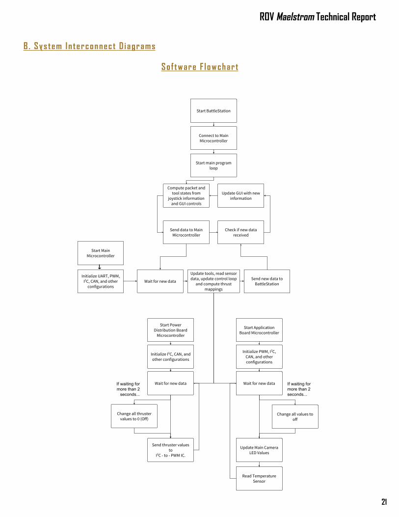
V. Software Design RationaleSof tware Overv iewROV Maelstrom comes with software guaranteeing easy control, usability, and strong reliability. Proven Robotics has written custom software that runs on a topside computer. This software, dubbed the BattleStation, was designed for ease of control and safety awareness. The BattleStation communicates with the embedded microcontrollers on the ROV. The embedded software controls the tooling, reads the sensors, and implements a control loop for improved maneuverability.
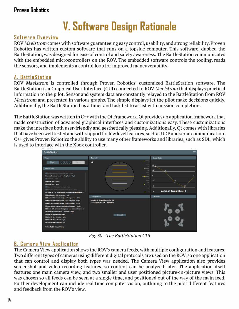
A . Ba t t l eS ta t i onROV Maelstrom is controlled through Proven Robotics’ customized BattleStation software. The BattleStation is a Graphical User Interface (GUI) connected to ROV Maelstrom that displays practical information to the pilot. Sensor and system data are constantly relayed to the BattleStation from ROV Maelstrom and presented in various graphs. The simple displays let the pilot make decisions quickly. Additionally, the BattleStation has a timer and task list to assist with mission completion.
The BattleStation was written in C++ with the Qt Framework. Qt provides an application framework that made construction of advanced graphical interfaces and customizations easy. These customizations make the interface both user-friendly and aesthetically pleasing. Additionally, Qt comes with libraries that have been well tested and with support for low level features, such as UDP and serial communication. C++ gives Proven Robotics the ability to use many other frameworks and libraries, such as SDL, which is used to interface with the Xbox controller.
B . Camera V iew App l i ca t i onThe Camera View application shows the ROV's camera feeds, with multiple configuration and features. Two different types of cameras using different digital protocols are used on the ROV, so one application that can control and display both types was needed. The Camera View application also provides screenshot and video recording features, so content can be analyzed later. The application itself features one main camera view, and two smaller and user positioned picture-in-picture views. This was chosen so all feeds can be seen at a single time, and positioned out of the way of the main feed. Further development can include real time computer vision, outlining to the pilot different features and feedback from the ROV's view.
Fig. 30 - The BattleStation GUI
15
ROV Maelstrom Technical Report
C . Movement Contro lThe BattleStation and Xbox Controller maneuvers and controls ROV Maelstrom. The controls are similar to conventional driving games and are configurable for the pilot’s preferences. Different precision settings are implemented, which change input sensitivity.
New this year, Proven Robotics implemented a more advanced thrust mapping algorithm that uses a linear transformation on the six dimensional force and torque vectors, to produce an eight dimensional motor thrust output. This change allows for dynamically changing the transformation vector, in case of thruster failure or repositioning, and still outputting the desired movement. This means the ROV can still be controllable, even with failures of multiple thrusters. Another feature of thrust mapping is a controllable pivot, that provide a point about which the ROV would rotate. It can be directly changed in the BattleStation to a point such as the Main Manipulator, making it easier to retrieve items.
The thrust mapping also enables an easier implementation of a proportional-integral (PI) controller, used for stabilization in all 6 degrees. By using the rotational and depth data from the Navigation Board and the horizontal plane position estimates from the sonar positioning system, each of the ROV's location and rotation axes can be individually locked. This makes maneuverability easier, such as when needing to stay at a specific depth while inserting the ESP Cable Connector.
D . Te ther Commun ica t ionsCommunication from the Control Center to ROV is done with one Ethernet cable and a network router. The router provides the ROV's Main Microcontroller Board, three cameras and the BattleStation an IP address that is used to communicate between devices. Transmission between the BattleStation and Main Microcontroller Board is done with the User Datagram Protocol (UDP), a connectionless protocol for sending messages that is commonly used on the Internet. Using a full featured Internet protocol was essential, so the camera feeds and ROV data could be transmitted over the same Ethernet cable. It was chosen over Transmission Control Protocol (TCP) for its messaged based formation, speed, and smaller overhead. The Main Microcontroller Board contains hardware that listens and transmit data over UDP. The BattleStation broadcasts UDP messages that will be picked up by the Main Microcontroller Board. Data is sent from the BattleStation to the ROV every 10 ms, which provides near-instantaneous response to the pilot's input. Similarly, data from the ROV's sensors, tools and other systems is collected on the Main Microcontroller and sent to the BattleStation every 10 ms for control feedback and data collection. Pre structured packets were designed that pack all commands and data between the ROV and BattleStation into the smallest possible size, ensuring no bit is transmitted unnecessarily. The packet structure also defines the type of message, which allows for future additions to the packet spec. All data packets also have a checksum, computed on the sender’s side and verified on the receiver’s end to avoid data corruption in the transmission. An 8-bit cyclic redundancy algorithm is used for fast computation, while providing unique outputs for different messages.
E . CAN Bus Commun ica t ionThree microcontrollers were chosen this year to distribute work between boards, however, data needed to be transmitted quickly and reliably between all three. Proven Robotics chose to use the CAN protocol, commonly used in cars and other vehicles, to communicate between the microcontrollers. This protocol allows multiple controllers to freely communicate on a bus without crosstalk. Additionally, CAN is designed with an error check that ensures reliable information can be transmitted in noisy environments. Another feature of the CAN protocol is message based communication, avoiding issues of locating the start and end of data packets through specific characters in a data stream. These features make it easier and more reliable than serial or I2C communication.
Proven Robotics
16
VI. LogisticsA. Company Organ i za t i onProven Robotics was composed of four distinct departments to properly delegate the responsibilities of designing, manufacturing, and testing the ROV. The mechanical, electrical, and software department were all headed by individual department leads who reported directly to the CEO. This facilitated a system where a common vision was shared between the departments while allowing specialties to develop. In addition to the three primary departments, an administrative department helped the CEO with various responsibilities ranging from sponsorship acquisition to technical report writing.
B . Pro jec t ManagementProven Robotics employed a Gantt chart to guide the decisions to produce ROV Maelstrom in a timely fashion. The schedule was divided into four main phases: training, design, build, and testing. Inexperienced employees were trained immediately at the beginning of the competition year. Depending on their interest, they focused on SolidWorks design, EAGLE PCB design, or software that consists of C++ and the Qt framework. After proficiency was obtained, the company moved into the design phase. Before the mission specifications were released the company focused on the ROV core components such as the frame, cameras, power conversion, and hydraulics. Once the company received the full mission specifications the mission specific tools were designed and the previous designs were fine-tuned. The design phase was particularly stressed to ensure any oversights in the future were minimized. Ideas were first brainstormed and discussed before drafting them in SolidWorks or EAGLE. After the designs were analyzed and critiqued at a formal design review, the company moved into the build phase. Frame and tools were machined and assembled, the circuit boards were printed and populated, and the software code was written. Finally, Proven Robotics entered the testing phase where everything was verified. This phase also consisted of pilot practice and regional qualification.
In order to effectively meet these deadlines, various productivity software tools were utilized. GitHub was the version control system of choice for software and PCB designs, while GrabCAD was used for SolidWorks designs. Both of these systems enabled multiple people to edit the designs while preserving previous versions. Additionally, the company employed the use of Slack to facilitate company-wide communication which provided the ability of separate “channels” that focused on certain parts of the company.
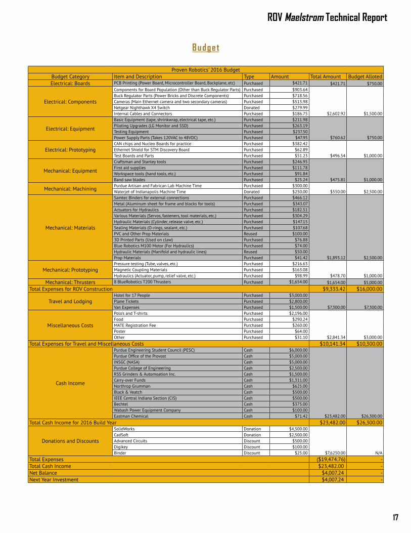
C . Pro jec t Cos t ing and BudgetProven Robotics began the year with a budget created from referencing the previous years’ expenses. The budget included all projected administrative and vehicle expenditures. Proven Robotics also pays for travel and lodging for as many employees as possible. Funds are procured through writing grants, soliciting donations, and applying for school based funding.
Proven Robotics follows a strict budget plan with set amounts allocated to each section of the budget. However, as can be seen on the following page, sometimes Proven Robotics needed to underspend in some categories and overspend in other categories. This is only done if absolutely needed and the overall budget does not change to ensure the company maintains within their financial means. For example, $7,500 was originally allocated for thrusters and machining. However, it soon became apparent that money could be saved in these categories and would be better utilized in electrical components. The company collected and analyzed the usage of the funds through the team's custom software, Boiler Books, which was used for tracking expenses and income.
17
ROV Maelstrom Technical Report
Proven Robotics' 2016 BudgetBudget Category Item and Description Type Amount Total Amount Budget AllotedElectrical: Boards PCB Printing (Power Board, Microcontroller Board, Backplane, etc) Purchased $421.71 $421.71 $750.00
Electrical: Components
Components for Board Population (Other than Buck Regulator Parts) Purchased $903.64
$2,602.92 $1,500.00
Buck Regulator Parts (Power Bricks and Discrete Components) Purchased $718.56Cameras (Main Ethernet camera and two secondary cameras) Purchased $513.98Netgear Nighthawk X4 Switch Donated $279.99Internal Cables and Connectors Purchased $186.75
Electrical: Equipment
Basic Equipment (tape, shrinkwrap, electrical tape, etc.) Purchased $211.98
$760.62 $750.00
Piloting Upgrades (LG Monitor and SSD) Purchased $263.19Testing Equipment Purchased $237.50Power Supply Parts (Takes 120VAC to 48VDC) Purchased $47.95
Electrical: PrototypingCAN chips and Nucleo Boards for practice Purchased $382.42
$496.54 $1,000.00Ethernet Shield for STM Discovery Board Purchased $62.89Test Boards and Parts Purchased $51.23
Mechanical: Equipment
Craftsman and Stanley tools Purchased $246.95
$475.81 $1,000.00
First aid supplies Purchased $111.78Workspace tools (hand tools, etc.) Purchased $91.84Band saw blades Purchased $25.24
Mechanical: MachiningPurdue Artisan and Fabrican Lab Machine Time Purchased $300.00
$550.00 $2,500.00Waterjet of Indianapolis Machine Time Donated $250.00
Mechanical: Materials
Samtec Binders for external connections Purchased $466.12
$1,893.12 $2,500.00
Metal (Aluminum sheet for frame and blocks for tools) Purchased $343.07Actuators for Hydraulics Purchased $182.51Various Materials (Servos, fasteners, tool materials, etc.) Purchased $304.29Hydraulic Materials (Cylinder, release valve, etc.) Purchased $147.15Sealing Materials (O-rings, sealant, etc.) Purchased $107.68PVC and Other Prop Materials Reused $100.003D Printed Parts (Used on claw) Purchased $76.88Blue Robotics M100 Motor (For Hydraulics) Purchased $74.00Hydraulic Materials (Manifold and hydraulic lines) Reused $50.00Prop Materials Purchased $41.42
Mechanical: PrototypingPressure testing (Tube, valves, etc.) Purchased $216.63
$478.70 $1,000.00Magnetic Coupling Materials Purchased $163.08Hydraulics (Actuator, pump, relief valve, etc.) Purchased $98.99
Mechanical: Thrusters 8 BlueRobotics T200 Thrusters Purchased $1,654.00 $1,654.00 $5,000.00Total Expenses for ROV Construction $9,333.42 $16,000.00
Travel and LodgingHotel for 17 People Purchased $3,000.00
$7,300.00 $7,300.00Plane Tickets Purchased $2,800.00Van Expenses Purchased $1,500.00
Miscellaneous Costs
Polo’s and T-shirts Purchased $2,196.00
$2,841.34 $3,000.00
Food Purchased $290.24MATE Registration Fee Purchased $260.00Poster Purchased $64.00Other Purchased $31.10
Total Expenses for Travel and Miscellaneous Costs $10,141.34 $10,300.00
Cash Income
Purdue Engineering Student Council (PESC) Cash $6,000.00
$23,482.00 $26,300.00
Purdue Office of the Provost Cash $5,000.00INSGC (NASA) Cash $5,000.00Purdue College of Engineering Cash $2,500.00RSS Grinders & Automoation Inc. Cash $1,500.00Carry-over Funds Cash $1,311.00Northrop Grumman Cash $625.00Black & Veatch Cash $500.00IEEE Central Indiana Section (CIS) Cash $500.00Bechtel Cash $375.00Wabash Power Equipment Company Cash $100.00Eastman Chemical Cash $71.42
Total Cash Income for 2016 Build Year $23,482.00 $26,300.00
Donations and Discounts
SolidWorks Donation $4,500.00
$7,6250.00 N/A
CadSoft Donation $2,500.00Advanced Circuits Discount $500.00Digikey Discount $100.00Binder Discount $25.00
Total Expenses ($19,474.76) -Total Cash Income $23,482.00) -Net Balance $4,007.24) -Next Year Investment $4,007.24) -
Budget
Proven Robotics
18
VII. ConclusionA. Cha l l engesThroughout the build and design process various challenges that were faced. The biggest challenge was time management. During the training and design phase the company did fairly well staying on track; however, the building phase took longer than expected which led to a delay in reaching the testing phase. Balancing the busy schedule of volunteer employees, who had various priorities, made it difficult for the CEO and department leads to ensure all of the needed work got done in a timely fashion. However, by staying in constant communication with all employees, Proven Robotics was able to ensure they knew the importance of their system being ready for the final product. If the employee was still unable to properly contribute, the leadership would assign the task to another employee.
There were also various technical challenges throughout the year. While every system had its own unique challenges, some were more difficult to overcome than others. One unique challenge was the complex sonar positioning system. In order to ensure the sonar code could run on limited hardware, fixed precision numbers were required instead of floating point math. An appropriate scaling was needed to prevent underflow and overflow values while maintaining an acceptable amount of precision. The team consulted various resources, from veteran members to online resources and was able to successfully overcome the problem. Proven Robotics always does its best to acquire the needed knowledge to successfully complete a task, even talking to professors and previous Proven Robotics members when necessary.
B . Lessons Learned and Sk i l l s Ga inedA variety of diverse technical skills were learned by each employee. The mechanical department, learned how to design and manufacture parts. These employees started with learning various features of SolidWorks from basic design to FEA. They then fabricated the designed parts. This enabled them to follow their design from start to finish which showed the need for both good design and manufacturability. Electrical members learned how to start with technical requirements, devise the needed circuit, and then design the schematic and board layout in EAGLE. This cumulated in learning how to populate and test the boards. Similarly, software department employees learned how to design code on both custom embedded systems and a general purpose computer. During testing, software members also learned how to use basic electrical tools such as multimeters, digital logic analyzers, and oscilloscopes to aid in their debugging. Employees of all departments learned how to work together and communicate with eyes towards a common goal while taking into account their individual specialties. In addition to the countless technical skills acquired, the administrative team learned many lessons, the biggest was the need for effective delegation. With a forty-two person company, it was easy for some employees to be overlooked for a task they were otherwise capable of completing. It was learned that a system was needed to keep track of what needed to be done and who was working on what; however, it was discovered that this system could not become burdensome to the company. Proven Robotics attempted to use Trello in the beginning; however, in its given implementation it proved to take more time than it was worth. The most effective method used was creating a weekly to-do list by the department leads in a Google Document. This idea led the department's closer to a proper balance between needed documentation and scheduling while also ensuring it did not take so much time as to inhibit employee contribution towards productive technical endeavors.
C . Fu ture ImprovementsThe production of ROV Maelstrom was not without challenges and discovery. Thus Proven Robotics has recorded improvements and notes to consider for next year’s design. Planning ahead, not just for the time needed for design and physical labor, but for ordering items is important. There were times where employees were ready to work on an item but stock or components were not available. There was also a need to focus on starting complex items earlier. While it was tempting to get the easier items finished immediately, it often led to a lack of focus on complex items that take longer to complete. This could
19
ROV Maelstrom Technical Report
be done by breaking the final deadlines for completing items into various smaller tasks with shorter deadlines.
Electrically, Proven Robotics hopes to modularize the power conversion system next year. The company had difficulty debugging the DC-DC quarter brick converters because they were all connected to the same power system. To solve this problem, it is hoped to be able to separate each quarter brick such that they can be tested independently.
Due to the abstracted nature of this year’s software design, successive years can use code modules such as the thrust mapping, stabilization/PI controller, and hardware sensor libraries on future vehicles, enabling them to spend more time on improving reliability, and adding features such as computer vision and machine learning.
Mechanically, the final lessons learned from the open loop hydraulic system will dictate whether Proven Robotics will continue to use the system. It has yet to be tested as a fully integrated system, and utilization of the current hydraulic pump has already caused wear and tear, requiring the purchase of a replacement pump. Due to this, the company needs to devise a new more durable pump system for future years.
D . Re f l ec t i onsPurdue IEEE ROV has participated in the MATE competition eight years now. Each year individuals share their experiences and pass on the knowledge.
As the newly appointed Electrical Team Lead, this year has been both challenging and rewarding. Given that I had no prior leadership experience, I had to quickly learn what it took to be an effective leader. Yes, I learned all of the technical knowledge like every engineer should, but I learned that technical knowledge can only get you so far. I learned that an effective leader has to believe that the team can overcome any obstacle; he must have trust in his teammates to do any task; and he must have fun. When I look back at my time on the ROV team, what I remember will be my teammates and all of the fun moments I had with them. That is the reason why I am glad that I am on the ROV team.
-Luke McBee (Electrical Team Lead)
The IEEE ROV team has been one of the most influential part of my college experience so far. The most challenging obstacle I encountered while on the team was the fast pace of the team during the design and manufacturing stages. This forced me to work quicker than I was used to while also maintaining the same quality of work. My tasks with the Administrative Team were to communicate with companies and organizations to secure sponsorships for the team. This involved explaining what the team needs to accomplish this year, and reasons for them to sponsor us. Being part of the Administrative Team helped me develop a better understanding of the components of the ROV that I’m not directly working on, and a deeper understanding of how it works as a whole. Overall, my time on ROV has been invaluable to my development as an engineer. By applying the design skills such as SolidWorks that I learned on the team, as well as manufacturing skills, I am better prepared to handle my life as both a student and an engineer.
-Alex Ruffino (Sponsorship Coordinator and Mechanical Team)
This is my first time working on a technical team. ROV gave me the most beautiful memories in my first year. I learned how to do CAD modeling with SolidWorks, how to design a complex framework, and how to analyze a complex problem step by step. My teammates are so sweet: they took care of my poor English. As a non-mechanical major, I gained manufacturing experiences that I may never have the chance to do. Next time if you ask me what kind of tools I have used, my answer won’t be just a hammer anymore.
-Yuqin Sophia Duan (Software and Mechanical Team)
Proven Robotics
20
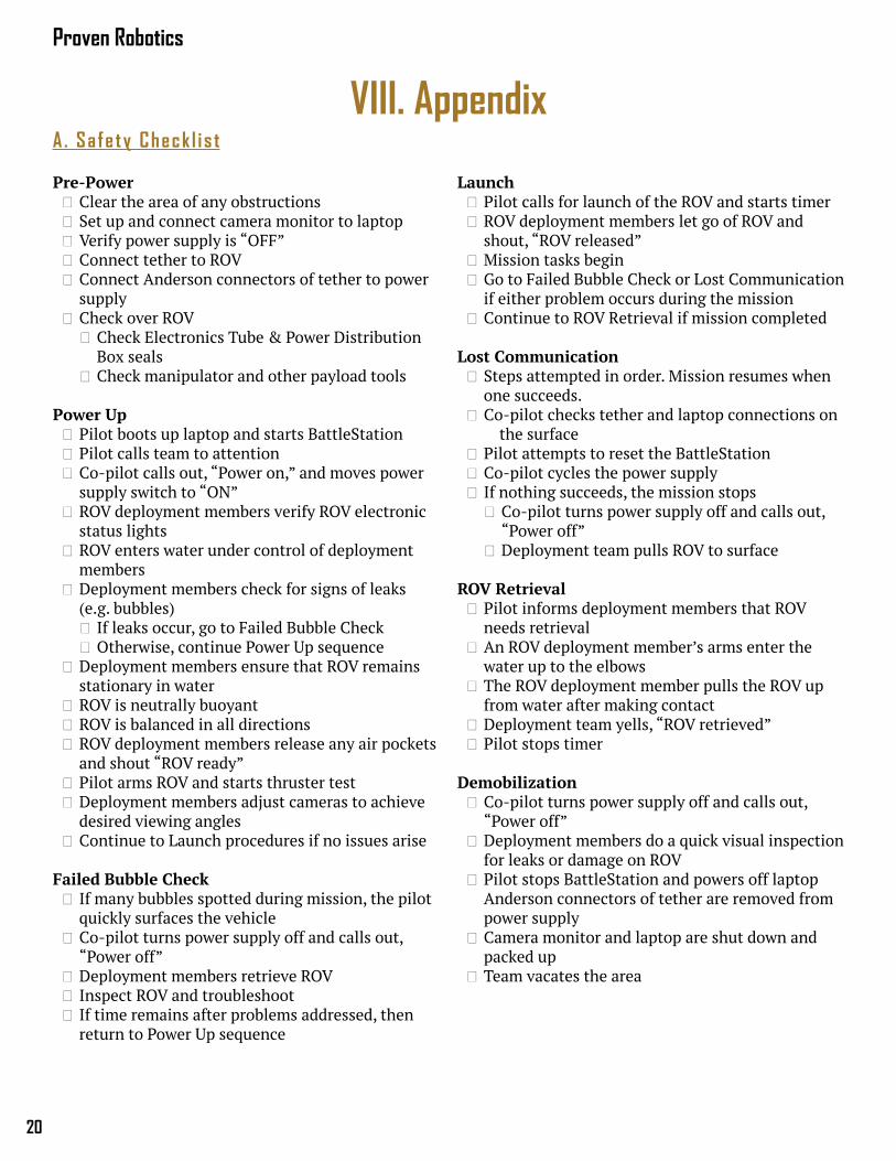
Launch Pilot calls for launch of the ROV and starts timer ROV deployment members let go of ROV and shout, “ROV released”
Mission tasks begin Go to Failed Bubble Check or Lost Communication if either problem occurs during the mission
Continue to ROV Retrieval if mission completed
Lost Communication Steps attempted in order. Mission resumes when one succeeds.
Co-pilot checks tether and laptop connections on the surface
Pilot attempts to reset the BattleStation Co-pilot cycles the power supply If nothing succeeds, the mission stops
Co-pilot turns power supply off and calls out, “Power off”
Deployment team pulls ROV to surface
ROV Retrieval Pilot informs deployment members that ROV needs retrieval
An ROV deployment member’s arms enter the water up to the elbows
The ROV deployment member pulls the ROV up from water after making contact
Deployment team yells, “ROV retrieved” Pilot stops timer
Demobilization Co-pilot turns power supply off and calls out, “Power off”
Deployment members do a quick visual inspection for leaks or damage on ROV
Pilot stops BattleStation and powers off laptop Anderson connectors of tether are removed from power supply
Camera monitor and laptop are shut down and packed up
Team vacates the area
VIII. AppendixA. Sa fe ty Check l i s t
Pre-Power Clear the area of any obstructions Set up and connect camera monitor to laptop Verify power supply is “OFF” Connect tether to ROV Connect Anderson connectors of tether to power supply
Check over ROV Check Electronics Tube & Power Distribution Box seals
Check manipulator and other payload tools
Power Up Pilot boots up laptop and starts BattleStation Pilot calls team to attention Co-pilot calls out, “Power on,” and moves power supply switch to “ON”
ROV deployment members verify ROV electronic status lights
ROV enters water under control of deployment members
Deployment members check for signs of leaks (e.g. bubbles)
If leaks occur, go to Failed Bubble Check Otherwise, continue Power Up sequence
Deployment members ensure that ROV remains stationary in water
ROV is neutrally buoyant ROV is balanced in all directions ROV deployment members release any air pockets and shout “ROV ready”
Pilot arms ROV and starts thruster test Deployment members adjust cameras to achieve desired viewing angles
Continue to Launch procedures if no issues arise
Failed Bubble Check If many bubbles spotted during mission, the pilot quickly surfaces the vehicle
Co-pilot turns power supply off and calls out, “Power off”
Deployment members retrieve ROV Inspect ROV and troubleshoot If time remains after problems addressed, then return to Power Up sequence
21
ROV Maelstrom Technical Report
B . Sys tem In terconnect D iagrams
Sof tware F lowchar t
Start BattleStation
Connect to Main Microcontroller
Start Main Microcontroller
Initialize UART, PWM, I2C, CAN, and other
configurationsWait for new data
Update tools, read sensor data, update control loop
and compute thrust mappings
Send new data to BattleStation
Start main program loop
Compute packet and tool states from
joystick information and GUI controls
Send data to Main Microcontroller
Check if new data received
Update GUI with new information
Start Power Distribution Board
Microcontroller
Initialize I2C, CAN, and other configurations
Wait for new data
Send thruster values to
I2C - to - PWM IC.
Change all thruster values to 0 (Off)
If waiting for more than 2
seconds...
Start Application Board Microcontroller
Initialize PWM, I2C, CAN, and other configurations
Wait for new data
Update Main Camera LED Values
Change all values to off
If waiting for more than 2 seconds...
Read Temperature Sensor
Proven Robotics
22
Power Sys tem In terconnect D iagram
Data Sys tem In terconnect D iagram
48 V Power Supply
40A Fuse Laptop Control
BattleStationSampling Unit
48V-12V Converter Box
M
Thruster 1
M
Thruster 2
M
Thruster 3
M
Thruster 4
M
Thruster 5
M
Thruster 6
M
Thruster 7
M
Thruster 8
M
Hydraulic Pump
Electronics Tube
Navigation & Sonar
Solenoid Boards
Temperature Sensor
Secondary Camera Box 1
Main Camera Tube
Secondary Camera Box 2
12V
12V
Hydrophone(Passive)
12V
12V
12V
12V
12V
12V
12V
48V
48V48V Switch
120Vac
5V
9V Battery 9V
~1mV
x4
12V
12V
5V 12V3.3V
12V
12V
12V
5V
Surface
Underwater
Fuse Calculations:8 thrusters @ 12V, 10A; pump @12V, 4A; Electronics Tube @12V, 3APower Consumption: 1,044W1,044W / 48V = 21.75 A, 21.75A * 1.5 = 32.625ANext standard fuse: 40A
Power System Interconnection Diagram (SID)
Xbox Controller
5V
M
Servo5V
3A Fuse
9V
Amplifier
Laptop Control
BattleStationSampling Unit Amplifier
48V-12V Converter Box
M
Thruster 1
M
Thruster 2
M
Thruster 3
M
Thruster 4
M
Thruster 5
M
Thruster 6
M
Thruster 7
M
Thruster 8
M
Hydraulic Pump
Electronics Tube
Navigation & Sonar
Solenoid Boards
Temperature Sensor
Secondary Camera Box 1
Main Camera Tube
Secondary Camera Box 2
PWM
PWM
Hydrophone(Passive)
PWM
PWM
PWM
PWM
PWM
PWM
PWM
USB
x4
CAN
I²C
SPII²C
IP
IP
IP
Surface
Underwater
Data System Interconnection Diagram (SID)
Xbox Controller
USB
UDPUDP
M
Servo
PWM
PWM
Analog Sensor Data
23
ROV Maelstrom Technical Report
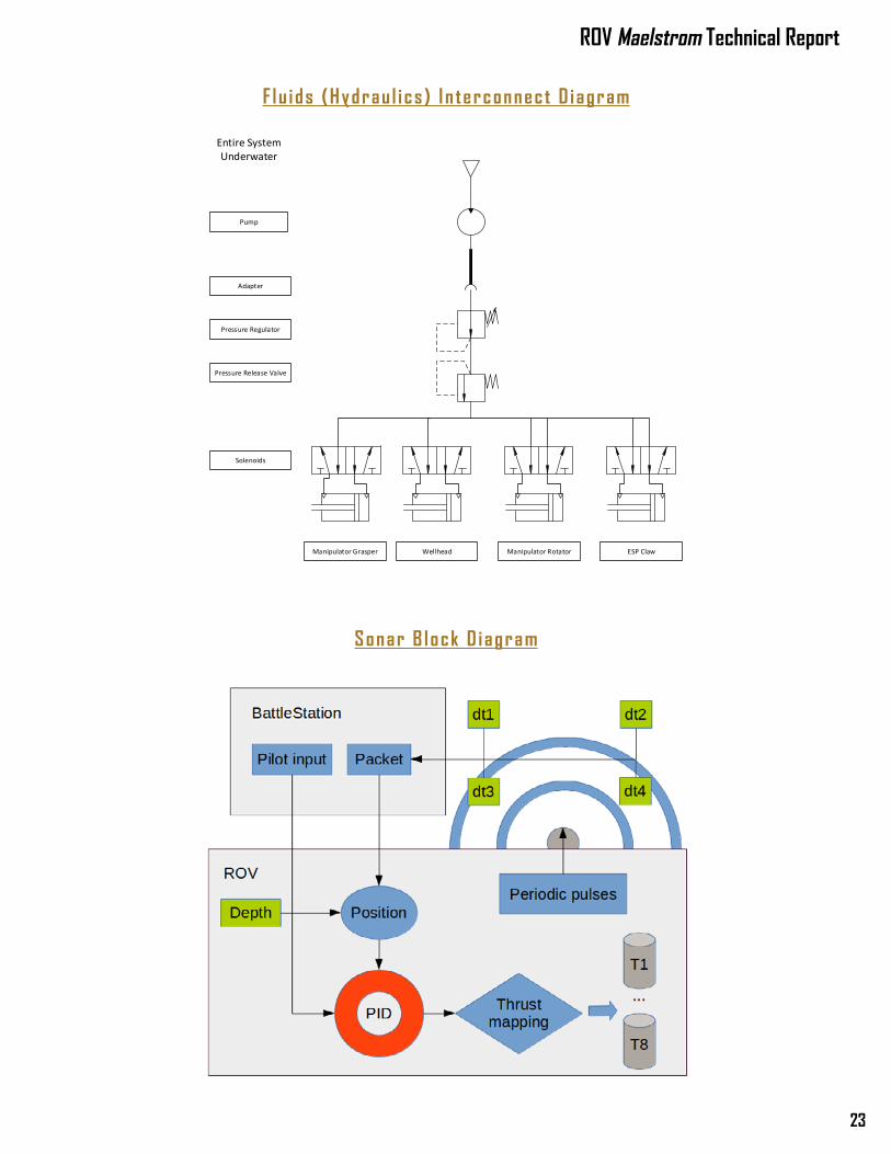
F lu ids (Hydrau l i cs ) I n terconnect D iagram
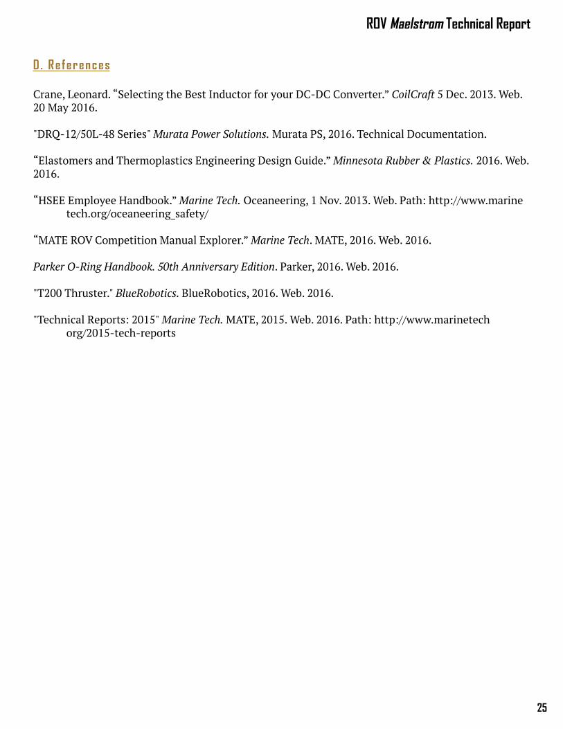
Sonar B lock D iagram
Manipulator Grasper
Solenoids
Pressure Regulator
Pump
Adapter
Wellhead
Pressure Release Valve
Manipulator Rotator ESP Claw
Entire System Underwater
Fluids System Interconnection Diagram (SID)

Proven Robotics
24
C . Acknowledgments
NetgearDigi-Key
Binder USAAdvanced CircuitsEastman Chemical
Waterjet Cutting of IndianaWabash Power Equipment Company
Proven Robotics Thanks:Parents and family for advice and support
Volunteer judges of the MATE CompetitionMATE Center for providing us with this opportunity
Purdue IEEE Student Branch for being a great parent organizationThe Boilermaker Aquatic Center and Jefferson High School for use of their pools
Seth Baklor, Michael Hayashi and Nicholas Molo for their continued guidance of the team
25
ROV Maelstrom Technical Report
D . Re ferences
Crane, Leonard. “Selecting the Best Inductor for your DC-DC Converter.” CoilCraft 5 Dec. 2013. Web. 20 May 2016.
"DRQ-12/50L-48 Series" Murata Power Solutions. Murata PS, 2016. Technical Documentation.
“Elastomers and Thermoplastics Engineering Design Guide.” Minnesota Rubber & Plastics. 2016. Web. 2016.
“HSEE Employee Handbook.” Marine Tech. Oceaneering, 1 Nov. 2013. Web. Path: http://www.marine tech.org/oceaneering_safety/
“MATE ROV Competition Manual Explorer.” Marine Tech. MATE, 2016. Web. 2016.
Parker O-Ring Handbook. 50th Anniversary Edition. Parker, 2016. Web. 2016.
"T200 Thruster." BlueRobotics. BlueRobotics, 2016. Web. 2016.
"Technical Reports: 2015" Marine Tech. MATE, 2015. Web. 2016. Path: http://www.marinetech org/2015-tech-reports