Embed Size (px)
Citation preview
WG-E Summary Beam Instruments and Interactions
Conveners Hee-Seock Lee (PAL)Tom Shea (ESS)Michiko Minty (BNL)
Organization 15 invited talks 2 discussion sessionsposters
Topics Beam instruments for high intensity acceleratorsBeam loss and activationCollimationBeam material interactions
M. Minty, HB2016, Malmö , Sweden 07/08/2016

Beam instrumentation for high intensity accelerators (5 talks)
Beam loss and activationCollimationBeam material interactions
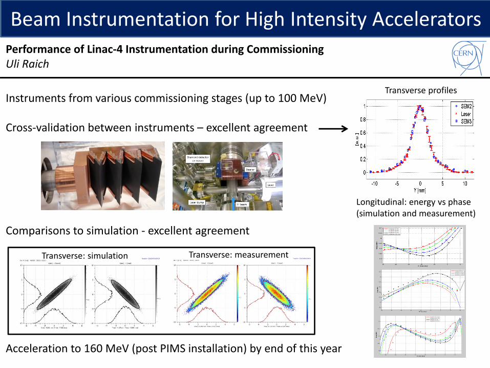
Instruments from various commissioning stages (up to 100 MeV)
Cross-validation between instruments – excellent agreement
Comparisons to simulation - excellent agreement
Acceleration to 160 MeV (post PIMS installation) by end of this year
Beam Instrumentation for High Intensity Accelerators
Transverse: simulation Transverse: measurement
Transverse profiles
Longitudinal: energy vs phase(simulation and measurement)
Performance of Linac-4 Instrumentation during CommissioningUli Raich

Complete suite of diagnostics successfully commissioned:
BLMs (ionization chambers and differential transformer msrmts.)beam current measurements (ACCT, FCT, NPCT, ACCT, MCT)BPMs (including cold button BPMs)BPMs for phase measurement, rms phase 0.4 deg, slide 12pair of BPMs for energy measurement , phase rms 1 degwire scannersemittance: double slit + FCelectron scanner
Good agreement between simulations and measurements
Future work: extend interlock systems, IPM, longitudinal profiles and tuning of longitudinal matching
Beam Instrumentation for High Intensity Accelerators
Presentation with overview and detail on beam commissioning of C-ADS linac beam instrumentation (p, 10 MeV, 10 mA, 100 kW).
Beam Commissioning of C-ADS Linac InstrumentationYanfeng Sui

Beam Instrumentation for High Intensity Accelerators
Linear IFMIF Prototype Accelerator (LIPAc) in Rokkasho, Japan supporting the International Fusion Materials Irradiation Facility (IFMIF) to test materials under very high neutron fluxes for future fusion reactors
DDCCBBAALIPAc…
• Commissioning has already begun, and is almost finish for the injector
• Assembling of the RFQ is in good progress. Beam commissioning should start in June 2017
µLoM for high intensity Linacs• µLoM are requested by Beam Dyn. for beam
tuning while keeping losses below 1W/m (hands-on maintenance)
• CVD diamonds should be good candidates for this purpose
Propriety: radiation tolerant, cryogenic… Counting rate estimates:
1W/m look reasonable and were checked experimentallyBG (vault + cavity emission) < 1W/m
Cautions: electron cavity emission (care about high Efield)FEE was tested and proposed
CVD diamond
HV
Signal
scattered neutron
3 diamonds per solenoid, inside the linac cryostat
R&D on micro-Loss Monitors for High Intensity Linacs like LIPAcJacques Marroncle

Beam Instrumentation for High Intensity Accelerators
New wire scanner design development for beam profile measurements, features all moveable components in vacuum, permanent magnet – based braking system. Extensive evaluation of systematic effects presented (fork shaft assembly: actuator motion, shaft twist, inertial deflection of fiber support fork, wire deflection)
Systematic studies presented based on analytical models (e.g. ANSYS), vibration measurements (strain gauge, piezoresistive effects) and more.
Device, with FPGA-based digital control, is under test in the SPS; anoptimized second design for the CERN Booster is in production. Thisdesign is envisioned to be the basis for the LHC injector rings with installation during the 2019/20 technical stop.
15 m/s PS scan
Developments in High-Precision Fast Wire Scanners for High Intensity ProtonAccelerators Bernd Dehning

Beam Instrumentation for High Intensity AcceleratorsDevelopments in Non-destructive Beam Profile Monitors, Carsten Peter Welsch
Synchrotron light – challenges: need to separate radiation from beam, large bending radius, depth-of-field issues, diffraction limit new developments with interferometry and core masking (coronograph)
Gas sheet/jet monitor (also 2-D image) – challenges: jet focussing, pressure in vacuum
Presentation with examples on beam monitoring options for high E and high I beams
Ionization profile monitors – challenges: required residual gas pressure, 1D onlyBeam-induced fluorescence – challenges: low cross section, isotropic light emission,
rest gas pressure requirements
Gas jet at the Cockcroft Institute :
Simulations (CST and WARP) underway, working on jet focussing ( with Fresnel zone plate)

Beam instrumentation for high intensity accelerators
Beam loss and activation (2 talks)CollimationBeam material interactions

Path to Beam Loss Reduction in the SNS Linac Using Measurements, Simulation and Collimation
Beam Loss and Activation
Presented development of tools for large dynamic range (DR) measurements, simulation and collimation to facilitate low loss linac tuning.
Alexander V. Aleksandrov
Have tools for control of rms, ‘matching’, yetnot guaranteed to prevent halo formation.
Detection lost particles not a halo measurement.
SNS linac is a good test bench for new methods development, reducing beam loss due to intra-beam stripping is a realistic first goal.
SNS 2.5 MeV Beam Test Facility to address: (1) how to construct 6D from 1D, 2D, 4D?(2) does mismatch create halo?
Reviewed measurement methods and the DR achievable including - 2D phase space measurement at low energy using double-slit emittance
measurements / at high energy using laser wires for H- beam- halo measurements using large DR wire scanners (1D) - reconstruction of 2D distributions from 1D profiles Compared methods.

Presented many beautiful measurements, two selected here:
1) 2D phase space (2-slit measurements) corresponding to 2 different times along the chopped linac pulse length
Path to Beam Loss Reduction in the SNS Linac Using Measurements, Simulation and Collimation Alexander V. Aleksandrov
~ 105 dynamic range or 20ns temporal resolution2) Comparison of phase space density measured at SNS MEBT and HEBT
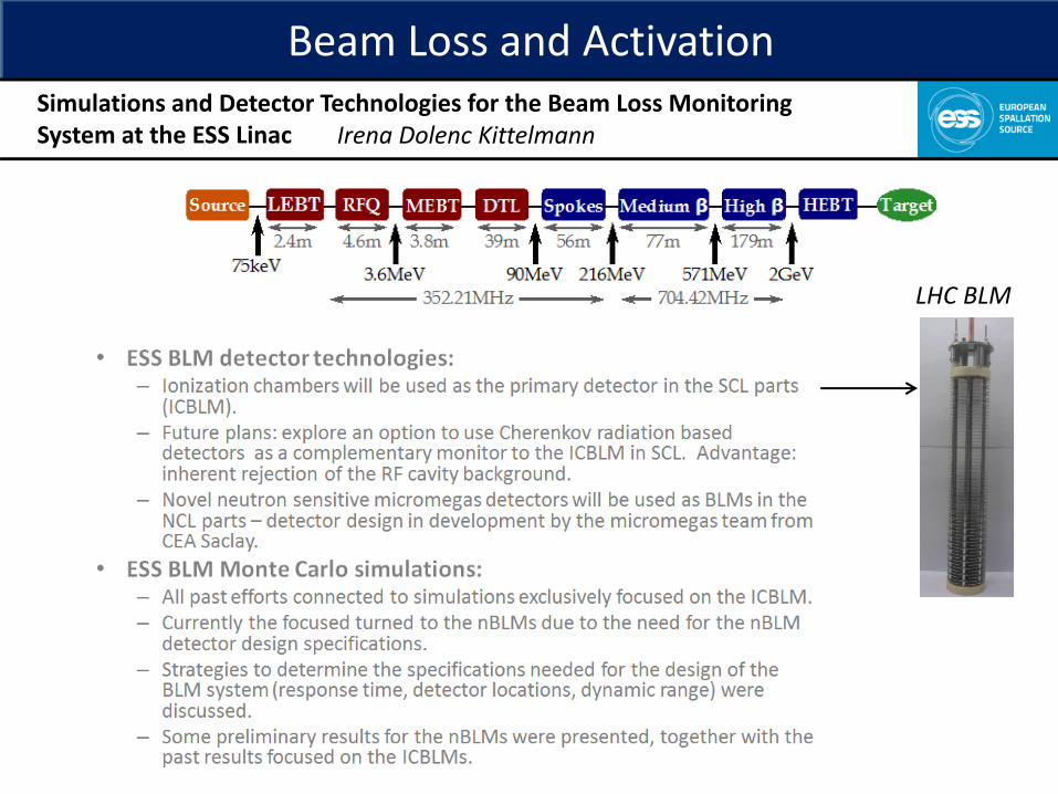
Beam Loss and ActivationSimulations and Detector Technologies for the Beam Loss Monitoring System at the ESS Linac Irena Dolenc Kittelmann
LHC BLM

Beam instrumentation for high intensity accelerators
Beam loss and activation Collimation (5 talks)Beam material interactions
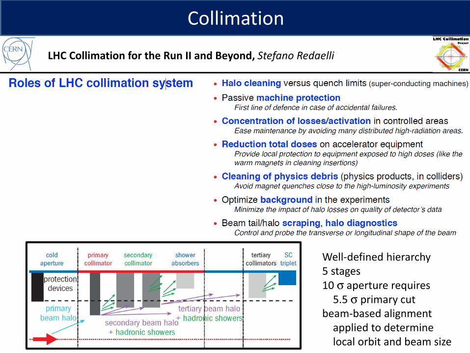
LHC Collimation for the Run II and Beyond, Stefano Redaelli
Collimation
Well-defined hierarchy5 stages10 σ aperture requires
5.5 σ primary cutbeam-based alignment
applied to determine local orbit and beam size

LHC Collimation for the Run Ii and Beyond, Stefano Redaelli
will employorbit positioninterlocks forlower β* reach
FLUKA+SixTrack+couplingversus measurement
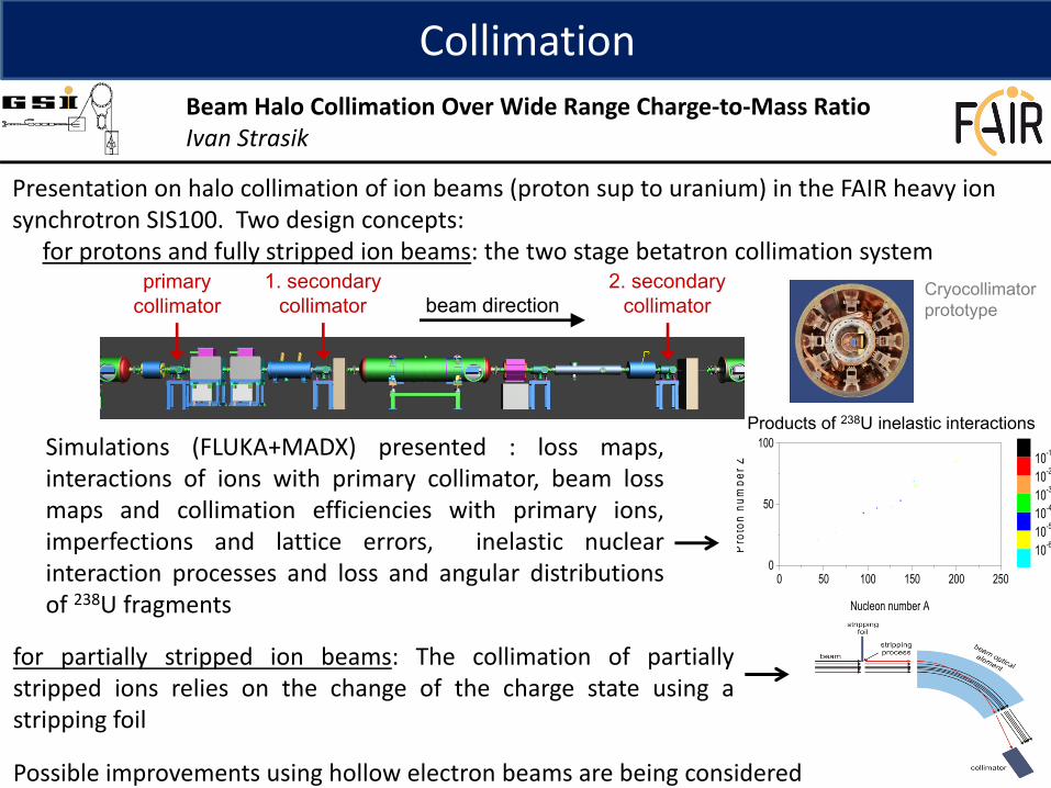
CollimationBeam Halo Collimation Over Wide Range Charge-to-Mass RatioIvan Strasik
Presentation on halo collimation of ion beams (proton sup to uranium) in the FAIR heavy ion synchrotron SIS100. Two design concepts:
for protons and fully stripped ion beams: the two stage betatron collimation system 1. secondary
collimatorprimary
collimator
rectangular aperture
beam direction2. secondary
collimator
Simulations (FLUKA+MADX) presented : loss maps,interactions of ions with primary collimator, beam lossmaps and collimation efficiencies with primary ions,imperfections and lattice errors, inelastic nuclearinteraction processes and loss and angular distributionsof 238U fragments
Cryocollimatorprototype
0 50 100 150 200 2500
50
100
Pro
ton
num
ber Z
Nucleon number A
10-610-510-410-310-210-1
for partially stripped ion beams: The collimation of partiallystripped ions relies on the change of the charge state using astripping foil
Possible improvements using hollow electron beams are being considered
Products of 238U inelastic interactions

CollimationNew Arrangement of Collimators of J-PARC Main RingMasashi Shirakata
History of collimation at the JPARC MR was presented
MR Beam Collimation SystemFirst design: Scraper-catchersFirst update: Replace of scraper (2012)Second update: Seven collimators (2014, design
loss capacity 3.5 kW) but later removed Third update: Add 2 4-axis collimators (2015)Fourth update: Requirements and future layout
2011, 140 kW 2013, 218 kW
RotatorTilter
Rotation
TiltTilt
(+)
(−)
(+)(−)

CollimationThe Application of the Optimization Algorithm in the Collimation System for CSNS/RCS, Hongfei Ji
The robust conjugate direction search method is applied to optimize the beam collimation system for Rapid Cycling Synchrotron (RCS) of the China Spallation Neutron Source (CSNS).
The uncontrolled beam loss of the total beam during acceleration can be reduced to 1.7×10⁻⁴,which is lower than that obtained by previous optimization.
As a result, an approach is established to efficiently give an optimal parameter combination ofthe secondary collimators for the present machine model.
The parameters of secondary collimators are optimized with RCDS algorithm based on- a two stage collimation system- a realistic intitial distribution arising from the injection painting scheme
The study presents a way to quickly find an optimal parameter combination of the secondary collimators for a machine model for preparation for CSNS/RCS commissioning.
Physics analysis and modelling methods presented.

CollimationCollimation Design and Beam Loss Detection at FRIBFelix Marti / Zhengzheng Liu
Presentation on simulations and design for collimation systems designed particularly for (1) ECR contaminants that are separated from primary beam after stripper

Collimation Design and Beam Loss Detection at FRIBFelix Marti / Zhengzheng Liu
(2) beam halo induced by stripper or bending arc (3) in FS1 potential charge exchange with residual gas due to higher pressure
Due to FRIB folded structure, linac faces big challenges on loss detection. A loss monitor network is designed to fulfill MPS requirements (15µs for large losses and 1 W/m slow losses)
Large intentional losses in FS1 make loss detection very difficult there. If the intentional losses are stable on the time scale of slow loss monitoring, we should be able to detect small uncontrolled losses

Beam instrumentation for high intensity accelerators
Beam loss and activation Collimation Beam material interactions (3 talks)

Recently achieved equivalent power of 1 MW to targets.
Beam power limited (0.5 MW) due to target pitting erosion / cavitation damage, which scales as 4th power of peak current density.
Several measures to mitigate: - gas micro-bubbles (offer ‘padding’ to cavitation bubbles)- dual-octupole beam flattening system: SAD code used as
beam tuning tool. Beam profiles controlled as designed;peak intensity will be reduced by 30%.
- “anti-correlated” painting reduced beam losses further
New 2D profile monitor developments.
Planning underway for new facilityat J-PARC for R&D of ADS.
Beam power will be ramped up to 1 MW after revisions to mercury target welds.
Octupole: 800 T/m3
0
1000
2000
Inte
nsity
(Arb
uni
t)
-100 0 1000
1000
2000
Position (mm)
Inte
nsity
(Arb
uni
t)
Horizontal
Vertical
Simulation and measurement
Fujikura rad-hard fiber
0 Gy 1 MGy 2 MGy
High Power Target Instrumentation at J-PARC for Neutron and Muon SourcesShin-ichiro Meigo
Beam-Material Interactions

Beam-Material Interactions
5000 MW-hr design, two recent target failures – costly to replace (1 M$ , 1 week)
Cause believed to be due totensile pressure wave / strain on Mercury vessel wall
Presentation of functional tests and test results with optical strain sensors:
new multi-mode fiber (2 week survival)new single-mode fiber (5 week survival)
Inner Reflecto
r Plug
Outer Reflector
Plug
Shutter
Target
sensors positioned on vessel nose-cone
– Is the strain on the target higher than we expected?– Are we hitting a resonance frequency?– How will we know if future mitigation methods are
working?
no dynamic stress build-up
Tests successfully addressed these questions:
Beam power on target at SNS
No additional cause for target failures found, no additional mitigation besides those already planned
Measurements of Beam Pulse Induced Mechanical Strain inside the SNS* Target Module, Willem Blokland

Beam-Material InteractionsBeam-Material Issues for Instrumentation in a 5 MW MonolithMonika Hartl
Linear proton accelerator
Neutron science systems
Rotating tungsten targetHelium cooled
Presentation of challenges for - multi-wired grids for beam profile monitoring, - TCs s and secondary emission blades for aperture monitoring - a luminescent coating for imaging the beam spot on the target. Radiation damage is to be expected and it is challenging to ensure full functionality of the diagnostic system over a set period of runtime.
Material choices for these components in the PBIP with respect to lifetime in a radiation field and operational criteria were reviewed.
Proton Beam Instrumentation Plug (PBIP)
Proton Beam Window (PBW)
Proton beam2 GeV/5 MW
Target Wheel
Moderator-Reflector Plug (MR Plug)

Discussion session #1• What instrumentation should be planned for rapid commissioning?• What are the lessons learned from the facilities that have been recently
commissioned or recommissioned after upgrade?
One starts with anaccelerator one doesn’t know , instruments one doesn’t know cross-checking instruments is vital to guarantee performance
(think: LINAC4 and C-ADS linac!)
For safety, instruments are crucial; redundancy is very important
• What did you wish you had but did not? What did you have that you could have left out? Linac energy at injection to RCS’s, better resolution TOF measurements
Need more diagnosticsfor commissioning than for operations; diagnostics for commissioning is insuranceSometimes
add diagnostics for better under-standing, but usually for R&D (not
operations)

Discussion session #2
For HI it shouldbe less because
of Bragg peak
1 W/m should be usedfor shielding but not foractual maintenance; most
accurate way is to calc-ulate (with e.g. GEANT)
to yield 10’s ofmW/m
1 W/m
Real Op.
LE proton or LE section
HE proton or HE section
• Is the limitation of 1 W/m still the rule of thumb? What is the suggestion based on two operational experiences at SNS and J-PARC ?
• Is any practical data of damage of SC material available from high energy accelerators? TBD, if not available, measurements should be performed
If activation of interest, use FLUKA to
know precisely loss per unit
length
For <25 MeV or SC cavities, 1 W/m is too high