Embed Size (px)
Citation preview
www.sensata.com
1
WHITE PAPER
WHAT YOU NEED TO KNOW ABOUT VIBRATION MONITORING ON YOUR ROTATING EQUIPMENT
In this first series that explores vibration sensing in the context of machine health monitoring, learn why you should monitor vibration on your rotating equipment, the language of vibration, the most important vibration analysis tool, and an overview of vibration sensors.
By Scott Mayo, Field Application Engineer – Smart Factory & Smart Building, Sensata TechnologiesOf all the technologies available in the world of machine health monitoring, more commonly known as condition monitoring, vibration monitoring has proven one of the most effective at facilitating predictive maintenance. If a plant operator has decided to implement a predictive maintenance program to manage the plant’s rotating assets, then an understanding of machine vibration is required.
WHAT IS MACHINE VIBRATION?Vibration is simply the repetitive motion of a mechanical system. All sufficiently complex mechanical systems can be modeled as a dynamic “mass-spring-damped” system. If such a system is mechanically excited by a hammer strike, for example, the response will be repetitive motion, at least for a brief time. That motion is vibration. In the case of a motor-fan set, the motor will start spinning once energized and, in addition to the machine doing the work it was intended to do, that system will vibrate in response to the mechanical excitation from the motor turning.
WHY MONITOR VIBRATION ON ROTATING MACHINES?Vibration monitoring is the dominant sensing technology in a machine condition monitoring program. Measuring and analyzing the vibration response of a rotating machine allows for the determination of the following:
• How the machine is behaving dynamically• If the machine is changing, particularly if its performance is deteriorating • The diagnosis of machine faults or the “condition” of the machine
Understanding these factors is the basis of vibration “condition monitoring.”
Figure 1
All sufficiently complex mechanical systems can be modeled as a dynamic “mass-spring-damped” system.
MACHINE HEALTH MONITORING SERIES PART 1: UNDERSTANDING VIBRATION MONITORING
www.sensata.com
2
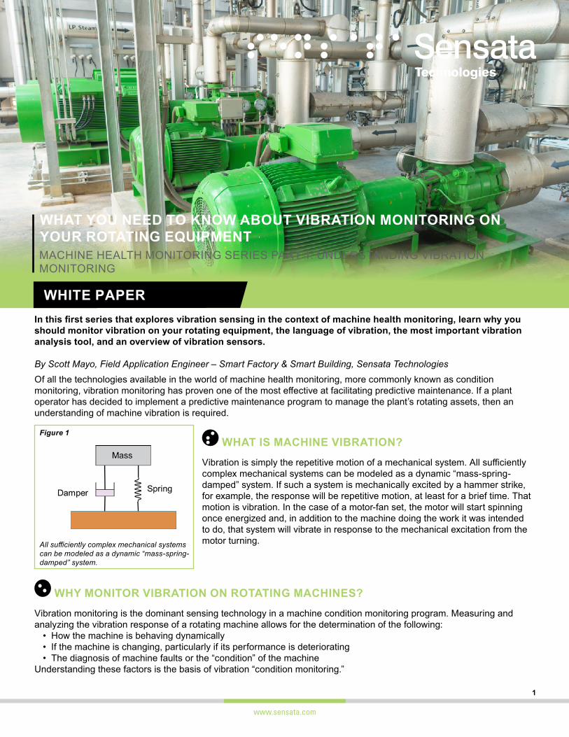
Why does this matter? Studies show that just over 50% of electric motor failures are due to premature bearing failures. Many of the rotating machine faults that can be diagnosed with vibration condition monitoring such as unbalance, misalignment and mechanical looseness, directly impact the motor’s bearings. If these machine faults can be detected in their early stages, they can be corrected, and the life of the bearings can be extended, thus saving on machine operating costs.
CONDITION MONITORING IS AN ESSENTIAL TOOL IN THE RELIABILITY PROFESSIONAL’S TOOLKIT The purpose of condition monitoring is to maximize the remaining useful life of rotating assets, thereby reducing operating costs and maximizing profits. Stated another way, the goal is to maximize uptime, thus increasing the reliability of the machine. All rotating equipment will eventually fail when it reaches a functional failure point due to natural wear on machine components such as bearings. But if operational anomalies occur, which can shorten useful life, can the operator intervene in time to mitigate the faults? It is the responsibility of the machine operator to run and maintain the machine such that its actual operating life is as close to the manufacturer’s design life as possible.
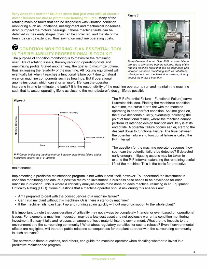
The P-F (Potential Failure – Functional Failure) curve illustrates this idea. Plotting the machine’s condition over time, the curve starts flat with the machine operating in near perfect condition. As time goes on, the curve descends quickly, eventually indicating the point of functional failure, where the machine cannot perform its intended design function and likely is at its end of life. A potential failure occurs earlier, starting the descent down to functional failure. The time between the potential failure and functional failure is called the P-F Interval.
The question for the machine operator becomes: how soon can the potential failure be detected? If detected early enough, mitigating actions may be taken to extend the P-F Interval, extending the remaining useful life of the machine. This is the basis for predictive
maintenance.
Implementing a predictive maintenance program is not without cost itself, however. To understand the investment in condition monitoring and ensure a positive return on investment, a business case needs to be developed for each machine in question. This is where a criticality analysis needs to be done on each machine, resulting in an Equipment Criticality Rating (ECR). Some questions that a machine operator should ask during this analysis are:
• Am I prepared to deal with the consequences of a machine failure?• Can I run my plant without this machine? Or is there a stand-by machine? • If the machine fails, can I get it up and running again quickly without major disruption to the whole plant?
It is important to note that consideration of criticality may not always be completely financial or even based on operational issues. For example, a machine in question may be a low-cost asset and not obviously warrant a condition monitoring investment. But say it fails and releases an amount of toxic material into the environment. What are the impacts to the environment and the surrounding community? What about regulatory penalties for such a release? Even if environmental effects are negligible, will there be public relations consequences for the plant operator with the surrounding community in such an event?
The answers to these questions, and others, can guide the machine operator when deciding whether to invest in a predictive maintenance program.
Figure 2
Motor-fan machine set. Over 50% of motor failures are due to premature bearing failures. Many of the rotating machine faults that can be diagnosed with vibration condition monitoring such as unbalance, misalignment, and mechanical looseness, directly impact the motor’s bearings
Figure 3
P-F Curve, indicating the time interval between a potential failure and a functional failure; the P-F Interval.
www.sensata.com
3
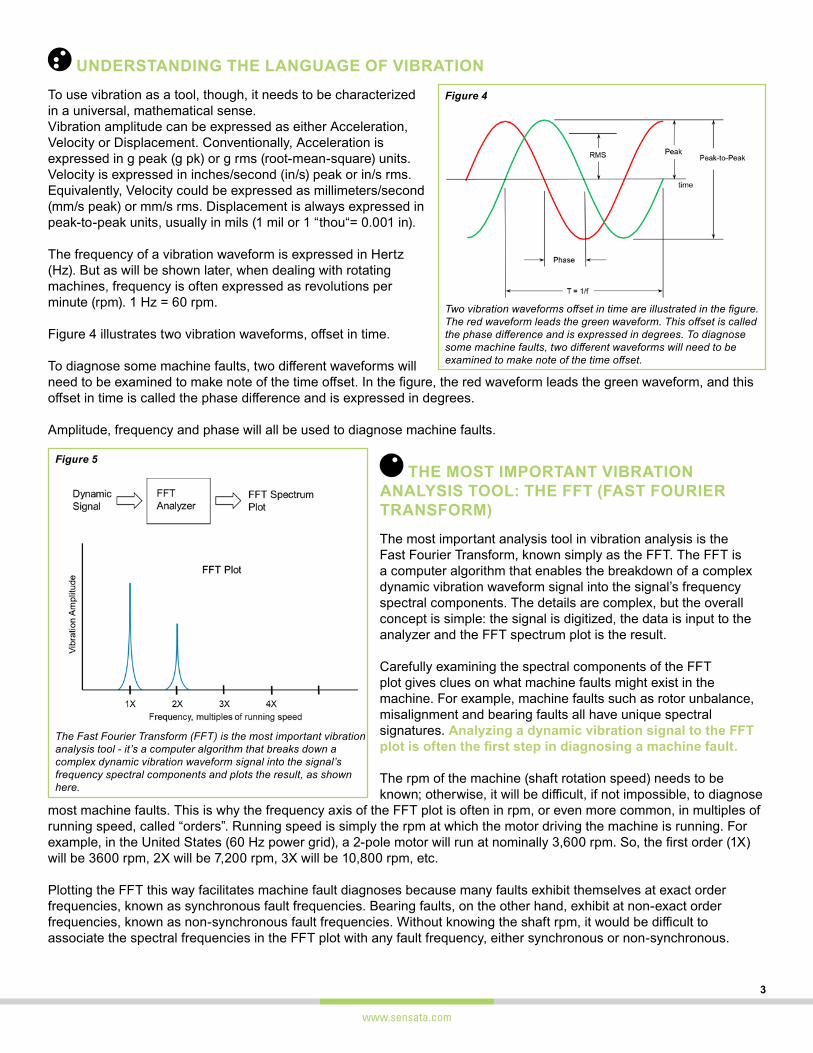
UNDERSTANDING THE LANGUAGE OF VIBRATION To use vibration as a tool, though, it needs to be characterized in a universal, mathematical sense.Vibration amplitude can be expressed as either Acceleration, Velocity or Displacement. Conventionally, Acceleration is expressed in g peak (g pk) or g rms (root-mean-square) units. Velocity is expressed in inches/second (in/s) peak or in/s rms. Equivalently, Velocity could be expressed as millimeters/second (mm/s peak) or mm/s rms. Displacement is always expressed in peak-to-peak units, usually in mils (1 mil or 1 “thou“= 0.001 in).
The frequency of a vibration waveform is expressed in Hertz (Hz). But as will be shown later, when dealing with rotating machines, frequency is often expressed as revolutions per minute (rpm). 1 Hz = 60 rpm.
Figure 4 illustrates two vibration waveforms, offset in time.
To diagnose some machine faults, two different waveforms will need to be examined to make note of the time offset. In the figure, the red waveform leads the green waveform, and this offset in time is called the phase difference and is expressed in degrees.
Amplitude, frequency and phase will all be used to diagnose machine faults.
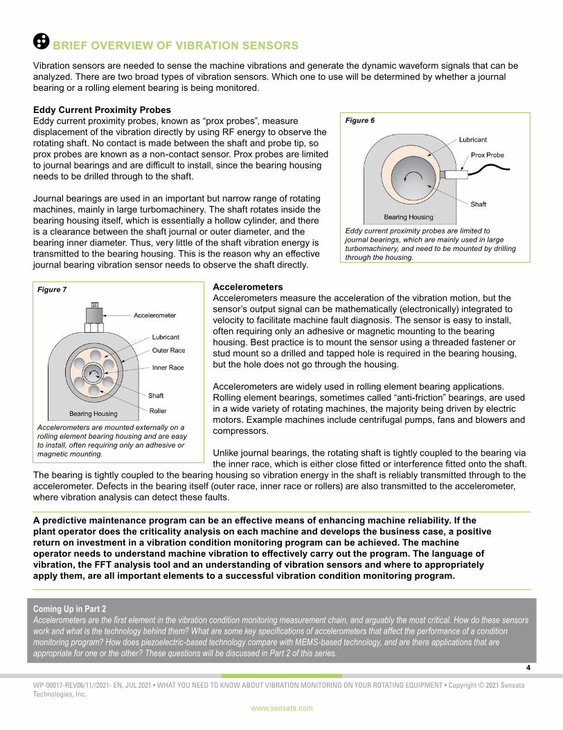
THE MOST IMPORTANT VIBRATION ANALYSIS TOOL: THE FFT (FAST FOURIER TRANSFORM)The most important analysis tool in vibration analysis is the Fast Fourier Transform, known simply as the FFT. The FFT is a computer algorithm that enables the breakdown of a complex dynamic vibration waveform signal into the signal’s frequency spectral components. The details are complex, but the overall concept is simple: the signal is digitized, the data is input to the analyzer and the FFT spectrum plot is the result.
Carefully examining the spectral components of the FFT plot gives clues on what machine faults might exist in the machine. For example, machine faults such as rotor unbalance, misalignment and bearing faults all have unique spectral signatures. Analyzing a dynamic vibration signal to the FFT plot is often the first step in diagnosing a machine fault.
The rpm of the machine (shaft rotation speed) needs to be known; otherwise, it will be difficult, if not impossible, to diagnose
most machine faults. This is why the frequency axis of the FFT plot is often in rpm, or even more common, in multiples of running speed, called “orders”. Running speed is simply the rpm at which the motor driving the machine is running. For example, in the United States (60 Hz power grid), a 2-pole motor will run at nominally 3,600 rpm. So, the first order (1X) will be 3600 rpm, 2X will be 7,200 rpm, 3X will be 10,800 rpm, etc.
Plotting the FFT this way facilitates machine fault diagnoses because many faults exhibit themselves at exact order frequencies, known as synchronous fault frequencies. Bearing faults, on the other hand, exhibit at non-exact order frequencies, known as non-synchronous fault frequencies. Without knowing the shaft rpm, it would be difficult to associate the spectral frequencies in the FFT plot with any fault frequency, either synchronous or non-synchronous.
Figure 4
Two vibration waveforms offset in time are illustrated in the figure. The red waveform leads the green waveform. This offset is called the phase difference and is expressed in degrees. To diagnose some machine faults, two different waveforms will need to be examined to make note of the time offset.
Figure 5
The Fast Fourier Transform (FFT) is the most important vibration analysis tool - it’s a computer algorithm that breaks down a complex dynamic vibration waveform signal into the signal’s frequency spectral components and plots the result, as shown here.
www.sensata.com
4
WP-00017-REV06/11//2021- EN, JUL 2021 • WHAT YOU NEED TO KNOW ABOUT VIBRATION MONITORING ON YOUR ROTATING EQUIPMENT • Copyright © 2021 Sensata Technologies, Inc.
BRIEF OVERVIEW OF VIBRATION SENSORS Vibration sensors are needed to sense the machine vibrations and generate the dynamic waveform signals that can be analyzed. There are two broad types of vibration sensors. Which one to use will be determined by whether a journal bearing or a rolling element bearing is being monitored.
Eddy Current Proximity ProbesEddy current proximity probes, known as “prox probes”, measure displacement of the vibration directly by using RF energy to observe the rotating shaft. No contact is made between the shaft and probe tip, so prox probes are known as a non-contact sensor. Prox probes are limited to journal bearings and are difficult to install, since the bearing housing needs to be drilled through to the shaft.
Journal bearings are used in an important but narrow range of rotating machines, mainly in large turbomachinery. The shaft rotates inside the bearing housing itself, which is essentially a hollow cylinder, and there is a clearance between the shaft journal or outer diameter, and the bearing inner diameter. Thus, very little of the shaft vibration energy is transmitted to the bearing housing. This is the reason why an effective journal bearing vibration sensor needs to observe the shaft directly.
AccelerometersAccelerometers measure the acceleration of the vibration motion, but the sensor’s output signal can be mathematically (electronically) integrated to velocity to facilitate machine fault diagnosis. The sensor is easy to install, often requiring only an adhesive or magnetic mounting to the bearing housing. Best practice is to mount the sensor using a threaded fastener or stud mount so a drilled and tapped hole is required in the bearing housing, but the hole does not go through the housing.
Accelerometers are widely used in rolling element bearing applications. Rolling element bearings, sometimes called “anti-friction” bearings, are used in a wide variety of rotating machines, the majority being driven by electric motors. Example machines include centrifugal pumps, fans and blowers and compressors.
Unlike journal bearings, the rotating shaft is tightly coupled to the bearing via the inner race, which is either close fitted or interference fitted onto the shaft.
The bearing is tightly coupled to the bearing housing so vibration energy in the shaft is reliably transmitted through to the accelerometer. Defects in the bearing itself (outer race, inner race or rollers) are also transmitted to the accelerometer, where vibration analysis can detect these faults.
A predictive maintenance program can be an effective means of enhancing machine reliability. If the plant operator does the criticality analysis on each machine and develops the business case, a positive return on investment in a vibration condition monitoring program can be achieved. The machine operator needs to understand machine vibration to effectively carry out the program. The language of vibration, the FFT analysis tool and an understanding of vibration sensors and where to appropriately apply them, are all important elements to a successful vibration condition monitoring program.
Coming Up in Part 2Accelerometers are the first element in the vibration condition monitoring measurement chain, and arguably the most critical. How do these sensors work and what is the technology behind them? What are some key specifications of accelerometers that affect the performance of a condition monitoring program? How does piezoelectric-based technology compare with MEMS-based technology, and are there applications that are appropriate for one or the other? These questions will be discussed in Part 2 of this series.
Figure 6
Eddy current proximity probes are limited to journal bearings, which are mainly used in large turbomachinery, and need to be mounted by drilling through the housing.
Figure 7
Accelerometers are mounted externally on a rolling element bearing housing and are easy to install, often requiring only an adhesive or magnetic mounting.