Embed Size (px)
Citation preview
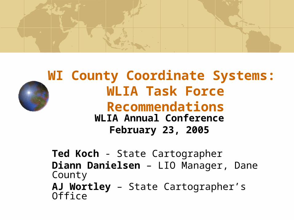
WI County Coordinate Systems: WLIA Task Force Recommendations
WLIA Annual ConferenceFebruary 23, 2005
Ted Koch - State CartographerDiann Danielsen – LIO Manager, Dane CountyAJ Wortley – State Cartographer’s Office
WI Coordinate Systems Task Force
Mission:Analyze and document the foundations of the WCCSInvestigate, analyze and document software implementations of WCCSInvestigate the redesign of the WCCSRegister WCCS with standards setting organizationDocument WCCS proceedingsDevelop user-focused documentationEvaluate and make recommendations regarding statutory changes Present TF recommendations to WLIA Board
Task Force MembersBrett Budrow, St Croix CountyTom Bushey, ESRIDiann Danielsen, Dane CountyJohn Ellingson, Jackson CountyBob Gurda, SCO (ended 4/30/04)Pat Ford, Brown CountyGene Hafermann, WI DOTDavid Hart, UW-Madison Sea GrantTed Koch, State Cartographer, ChairMike Koutnik, ESRIJohn Laedlein, WI Dept of Natural ResourcesTim Lehmann, Buffalo County
Gerald Mahun, Madison Area Technical CollegeDavid Moyer, Acting State Advisor, Nat’l Geodetic SurveyKent Pena, USDA - NRCSCarl Sandsnes, Ayres AssociatesGlen Schaefer, WI DOTJerry Sullivan, WI DOAPeter Thum, GeoAnalytics. Inc.Al Vonderohe, UW-Madison, Civil & Environmental EngineeringJay Yearwood, City of AppletonAJ Wortley, State Cartographer’s Office

Today’s Presentation
Ted – IntroductionDiann – WCCS: Why & What + ConcernsAJ – WCCS Design SolutionsTed – Summary: Where are we headed?
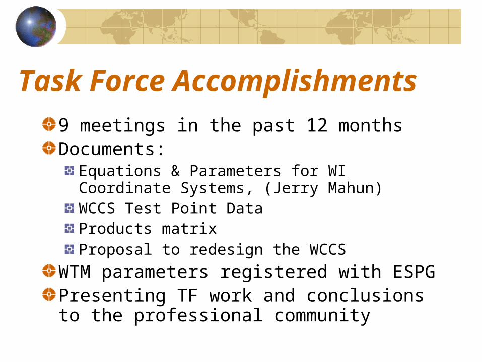
Task Force Accomplishments
9 meetings in the past 12 monthsDocuments:
Equations & Parameters for WI Coordinate Systems, (Jerry Mahun)WCCS Test Point DataProducts matrixProposal to redesign the WCCS
WTM parameters registered with ESPGPresenting TF work and conclusions to the professional community
Next:
Local coordinate systems and the WCCS: Why and What + Concerns
Diann Danielsen
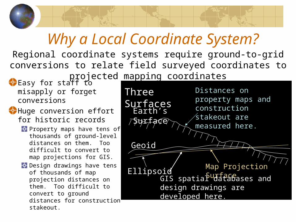
Why a Local Coordinate System?
Easy for staff to misapply or forget conversions
Huge conversion effort for historic records
Property maps have tens of thousands of ground-level distances on them. Too difficult to convert to map projections for GIS.Design drawings have tens of thousands of map projection distances on them. Too difficult to convert to ground distances for construction stakeout.
Regional coordinate systems require ground-to-grid conversions to relate field surveyed coordinates to projected mapping coordinates
Earth’s Surface
Geoid
EllipsoidMap Projection Surface
Distances on property maps and construction stakeout are measured here.
GIS spatial databases and design drawings are developed here.
Three Surfaces
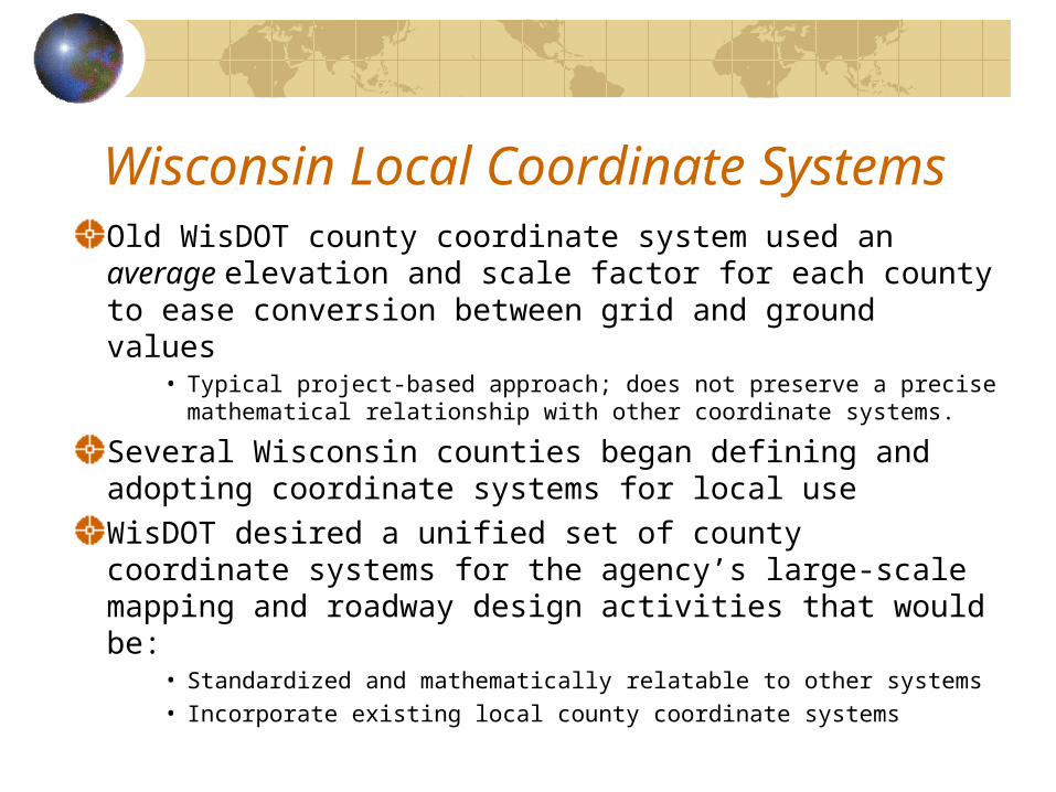
Wisconsin Local Coordinate SystemsOld WisDOT county coordinate system used an average elevation and scale factor for each county to ease conversion between grid and ground values
• Typical project-based approach; does not preserve a precise mathematical relationship with other coordinate systems.
Several Wisconsin counties began defining and adopting coordinate systems for local useWisDOT desired a unified set of county coordinate systems for the agency’s large-scale mapping and roadway design activities that would be:
• Standardized and mathematically relatable to other systems • Incorporate existing local county coordinate systems
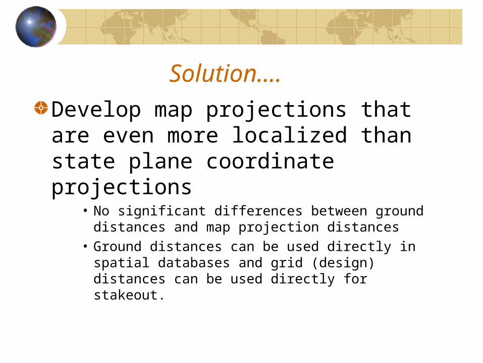
Solution….
Develop map projections that are even more localized than state plane coordinate projections
• No significant differences between ground distances and map projection distances
• Ground distances can be used directly in spatial databases and grid (design) distances can be used directly for stakeout.
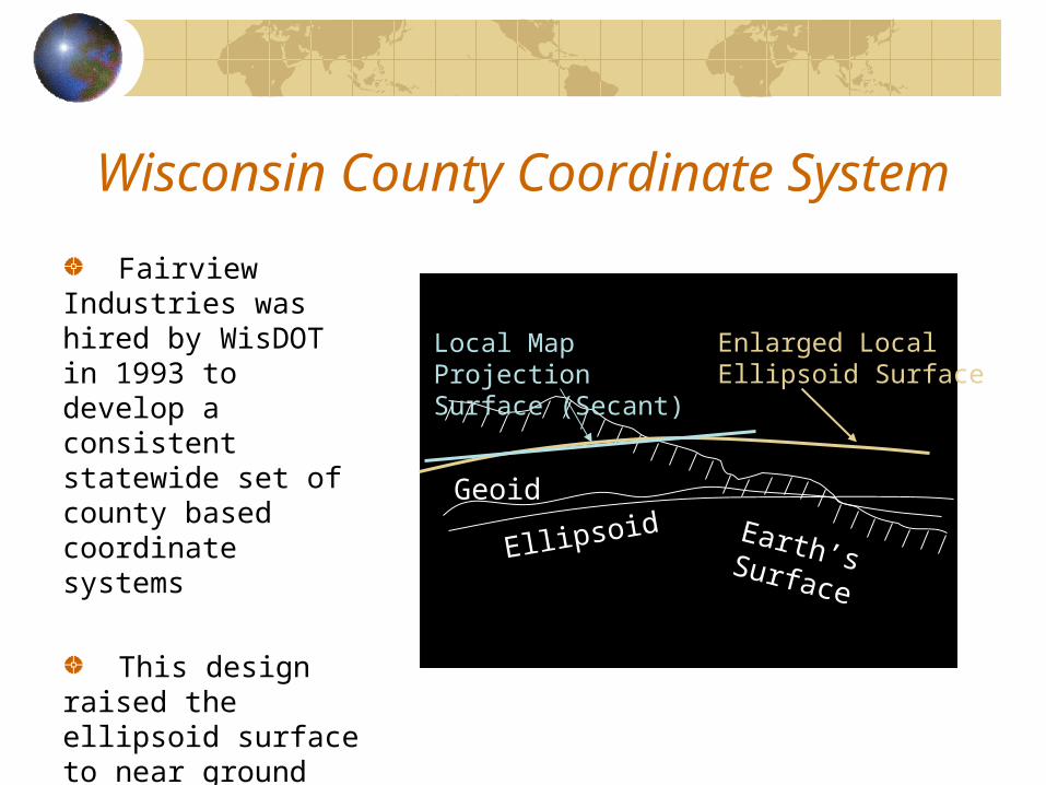
Wisconsin County Coordinate System
Fairview Industries was hired by WisDOT in 1993 to develop a consistent statewide set of county based coordinate systems
This design raised the ellipsoid surface to near ground level to minimize ground and grid differences
Geoid
Ellipsoid
Enlarged Local Ellipsoid Surface
Local Map Projection Surface (Secant)
Earth’s Surface
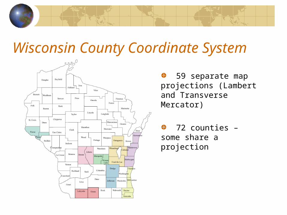
Wisconsin County Coordinate System
59 separate map projections (Lambert and Transverse Mercator)
72 counties – some share a projection
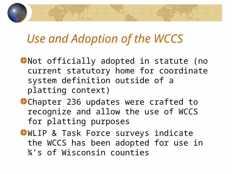
Use and Adoption of the WCCS
Not officially adopted in statute (no current statutory home for coordinate system definition outside of a platting context)Chapter 236 updates were crafted to recognize and allow the use of WCCS for platting purposesWLIP & Task Force surveys indicate the WCCS has been adopted for use in ¾’s of Wisconsin counties
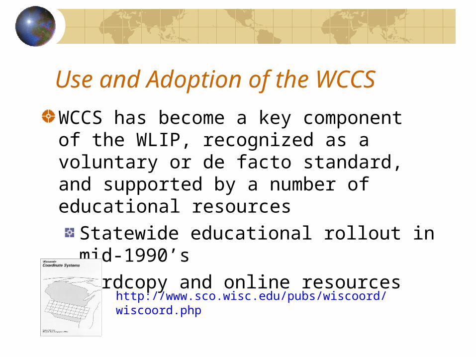
Use and Adoption of the WCCS
WCCS has become a key component of the WLIP, recognized as a voluntary or de facto standard, and supported by a number of educational resources
Statewide educational rollout in mid-1990’sHardcopy and online resources
http://www.sco.wisc.edu/pubs/wiscoord/wiscoord.php
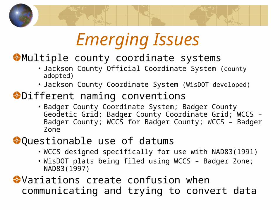
Emerging IssuesMultiple county coordinate systems
• Jackson County Official Coordinate System (county adopted)• Jackson County Coordinate System (WisDOT developed)
Different naming conventions• Badger County Coordinate System; Badger County
Geodetic Grid; Badger County Coordinate Grid; WCCS – Badger County; WCCS for Badger County; WCCS – Badger Zone
Questionable use of datums• WCCS designed specifically for use with NAD83(1991)• WisDOT plats being filed using WCCS – Badger Zone;
NAD83(1997)
Variations create confusion when communicating and trying to convert data
Other ConcernsVendor Implementation
Difficult because of the WCCS’s unconventional design; mathematically correct, but less understoodVendor implementation methodology differs, resulting in different coordinate values for the same feature
Lack of Formal RegistrationSome local systems adopted in ordinance; most are notNot registered with European Petroleum Survey Group/EPSG
• Aids consistent interpretation and implementation
Lack of State Custodian/OversightNo designated entity responsible for Wisconsin coordinate systems or other spatial reference parameters (land and water datums, geoid models, ellipsoids, etc)No single point of contact for assistance

WCCS: Design Solutions
AJ Wortley
Emerging IssueEnlarging the ellipsoid has the mathematical effect of modifying the underlying geodetic datum.This has caused difficulties in both the vendor and user communities.
Vendors want to support WCCS, but there is complexity.User community has limited understanding of datums and map projections.
WLIA Task Force
The WLIA Task Force on Wisconsin Coordinate Systems was formed early this year to address this and other issues associated with location referencing in Wisconsin.A question that emerged:Can the WCCS be re-designed so that:
1. There is no need to change the ellipsoid from GRS 80. That is, there will be one datum for all projections.
2. Coordinate differences between the existing and re-designed systems will be within negligible bounds. In this way, legacy databases and records will not have to be modified.
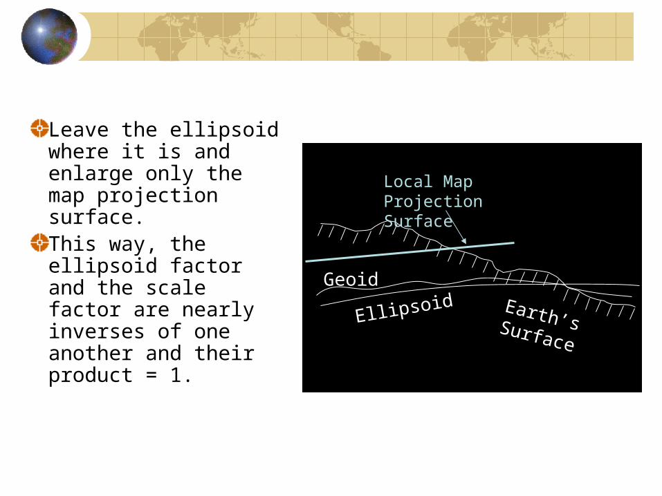
Leave the ellipsoid where it is and enlarge only the map projection surface. This way, the ellipsoid factor and the scale factor are nearly inverses of one another and their product = 1.
Map Projection SurfaceGeoid
Ellipsoid
Local Map Projection Surface
Earth’s Surface
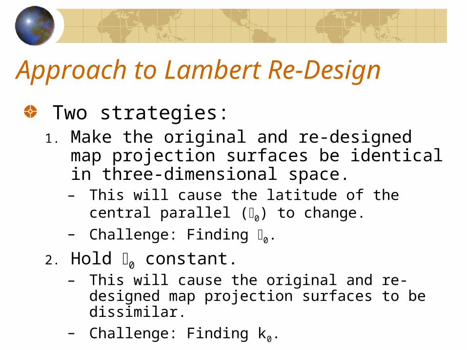
Approach to Lambert Re-Design
Two strategies:1. Make the original and re-designed map
projection surfaces be identical in three-dimensional space.– This will cause the latitude of the central
parallel (0) to change.– Challenge: Finding 0.
2. Hold 0 constant.– This will cause the original and re-designed
map projection surfaces to be dissimilar.– Challenge: Finding k0.
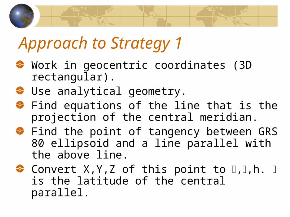
Approach to Strategy 1Work in geocentric coordinates (3D rectangular).Use analytical geometry.Find equations of the line that is the projection of the central meridian.Find the point of tangency between GRS 80 ellipsoid and a line parallel with the above line.Convert X,Y,Z of this point to ,,h. is the latitude of the central parallel.
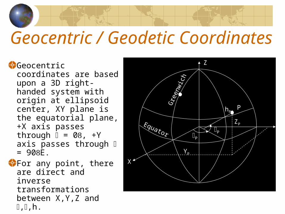
Geocentric / Geodetic Coordinates
Geocentric coordinates are based upon a 3D right-handed system with origin at ellipsoid center, XY plane is the equatorial plane, +X axis passes through = 0, +Y axis passes through = 90E.For any point, there are direct and inverse transformations between X,Y,Z and ,,h.
P
Y
Z
XP
Equator
Gre
enw
ich
P
P
P
X
Z
YP
ZP
hP
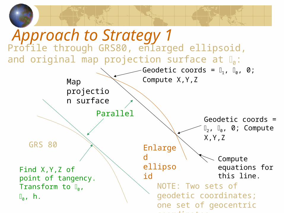
Approach to Strategy 1Profile through GRS80, enlarged ellipsoid, and original map projection surface at 0:
GRS 80 Enlarged ellipsoid
Map projection surface
Geodetic coords = 1, 0, 0; Compute X,Y,Z
Geodetic coords = 2, 0, 0; Compute X,Y,Z
Compute equations for this line.
Parallel
Find X,Y,Z of point of tangency. Transform to 0, 0, h. NOTE: Two sets of geodetic
coordinates; one set of geocentric coordinates.
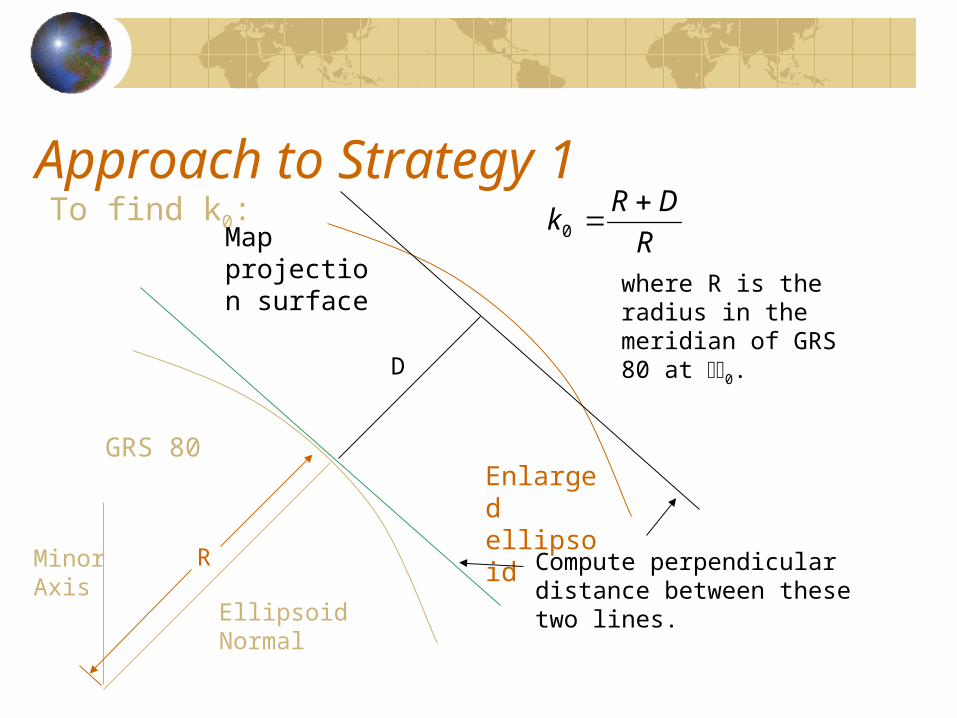
Approach to Strategy 1To find k0:
GRS 80Enlarged ellipsoid
Map projection surface
Compute perpendicular distance between these two lines.
D
where R is the radius in the meridian of GRS 80 at 0.
Ellipsoid Normal
Minor Axis
R
R
DRk
0
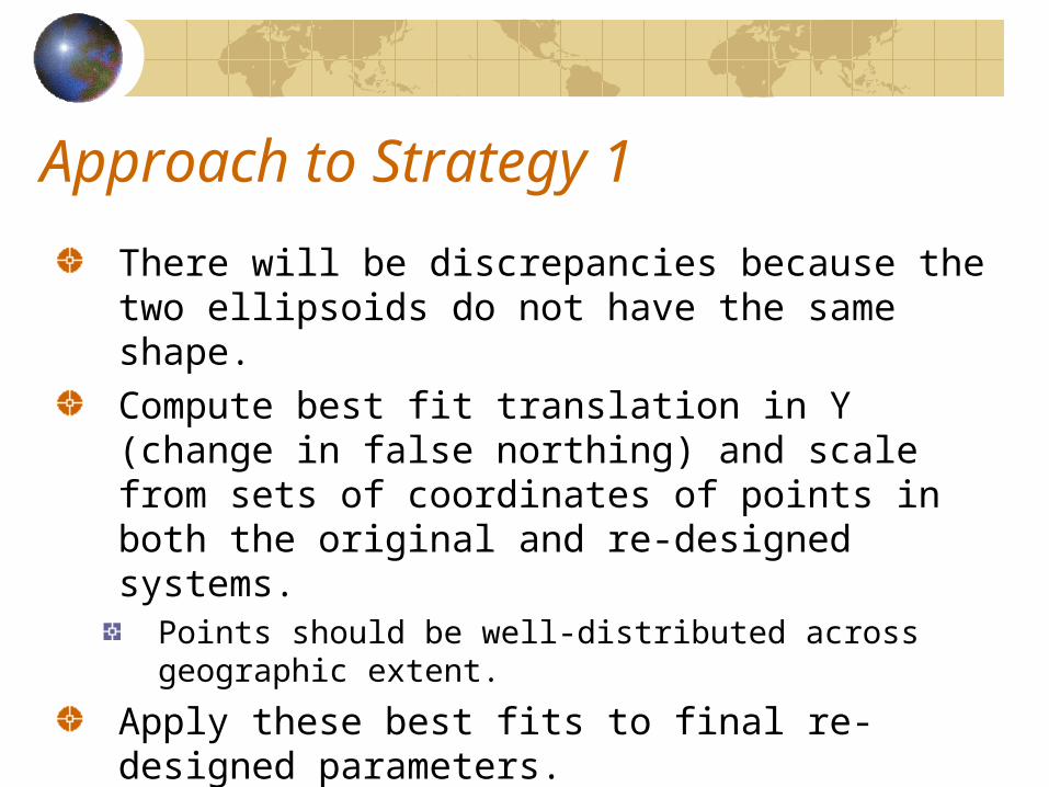
Approach to Strategy 1
There will be discrepancies because the two ellipsoids do not have the same shape.Compute best fit translation in Y (change in false northing) and scale from sets of coordinates of points in both the original and re-designed systems.
Points should be well-distributed across geographic extent.
Apply these best fits to final re-designed parameters.
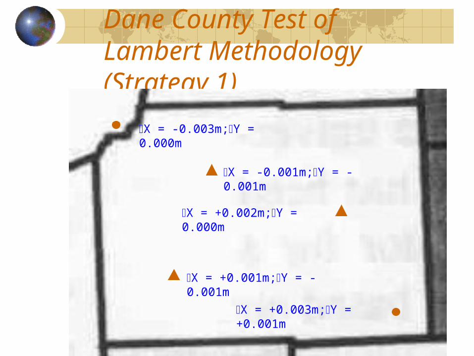
Dane County Test of Lambert Methodology (Strategy 1)
X = -0.003m;Y = 0.000m
X = +0.003m;Y = +0.001m
X = +0.001m;Y = -0.001m
X = -0.001m;Y = -0.001m
X = +0.002m;Y = 0.000m
Approach to Transverse Mercator Re-Design
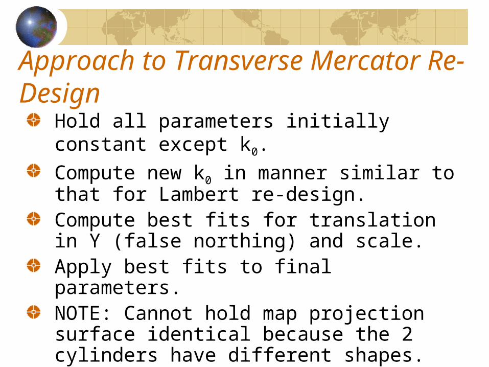
Hold all parameters initially constant except k0.
Compute new k0 in manner similar to that for Lambert re-design.Compute best fits for translation in Y (false northing) and scale.Apply best fits to final parameters.NOTE: Cannot hold map projection surface identical because the 2 cylinders have different shapes.
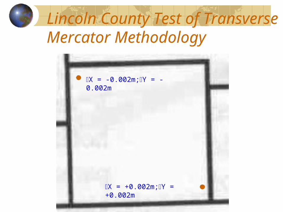
Lincoln County Test of Transverse Mercator Methodology
X = -0.002m;Y = -0.002m
X = +0.002m;Y = +0.002m
Conclusions
Under the re-design, all WCCS would have a single, common datum based upon the GRS 80 ellipsoid.Initial tests indicate that WCCS can be re-designed to within 5mm or better.The WLIA Task Force has deemed 5mm to be a negligible difference.The WLIA Task Force is recommending re-design.

Summary
Where are we headed?Ted Koch

Summary
Where are we headed?WCCS redesign proposal approved by
WLIA – October ’04WCCS redesign proposal approved by
WLIB – November ’04WLIB approves $35 K for redesign costsContract for redesign through a single
county using WLIB Strategic Initiative Grant
Summary
Where are we headed? (Continued)
WCCS redesign completed by Sept. ’05WCCS redesign documentation completed by Dec. ’05During ’05, TF will continue to address
issues of registration, legislation and usePrepare a TF final reportContinue to inform the community

Thank You
Questions???