Embed Size (px)
Citation preview
Research ArticleWideband RCS Reduction of Microstrip ArrayAntenna Based on Absorptive Frequency Selective Surface andMicrostrip Resonators
Jingjing Xue, Wen Jiang, and Shuxi Gong
National Laboratory of Antennas and Microwave Technology, Xidian University, Xi’an, Shaanxi 710071, China
Correspondence should be addressed to Wen Jiang; [email protected]
Received 21 January 2017; Revised 29 March 2017; Accepted 2 April 2017; Published 2 May 2017
Academic Editor: N. Nasimuddin
Copyright © 2017 Jingjing Xue et al. This is an open access article distributed under the Creative Commons Attribution License,which permits unrestricted use, distribution, and reproduction in any medium, provided the original work is properly cited.
An approach forwideband radar cross section (RCS) reduction of amicrostrip array antenna is presented anddiscussed.The schemeis based on the microstrip resonators and absorptive frequency selective surface (AFSS) with a wideband absorptive propertyover the low band 1.9–7.5 GHz and a transmission characteristic at high frequency 11.05GHz. The AFSS is designed to realizethe out-of-band RCS reduction and preserve the radiation performance simultaneously, and it is placed above the antenna withthe operating frequency of 11.05GHz. Moreover, the microstrip resonators are loaded to obtain the in-band RCS reduction. As aresult, a significant RCS reduction from 1.5GHz to 13GHz for both types of polarization has been accomplished. Compared withthe reference antenna, the simulated results exhibit that themonostatic RCS of the proposed array antenna in 𝑥- and 𝑦-polarizationcan be reduced as much as 17.6 dB and 21.5 dB, respectively. And the measured results agree well with the simulated ones.
1. Introduction
With the rapid development of the defense electronics andadvanced detection technology,much attention has been paidto the reduction of radar cross section (RCS). For a low-observable platform, antennas are the main contribution tothe total RCS [1]. Not all common approaches to reduceRCS are suitable for antennas on account of its feature toradiate and receive electromagnetic wave effectively. Thus itis a challenge to realize a remarkable RCS reduction andpreserve the radiation characteristic simultaneously.
Several methods have been proposed in literatures toreduce the RCS of antenna. Shaping the radiation patchor ground plane [2, 3] is one way to obtain the low RCSantennas, while the RCS reduction is usually in a relativelynarrow frequency band and the reduction effect is not ideal.With the random or ladder arrangement of antenna arrayelements [4, 5], the RCS of antenna array can be reduced,which provides an effective method to reduce the RCS ofmultielement arrays. The reactive impendence surface (RIS)is introduced in [6–8] and a two-layer mushroom-like RIS ispresented in [9] to realize the antenna miniaturization and
improve the radiation performance. And the mushroom-likestructures also can be utilized to reduce RCS of patch antennaarrays [10]. Chessboard configurations of the perfect electricconductor (PEC) and artificial magnetic conductors (AMC)obtain a 180∘ (±30∘) phase difference of the reflected wavesin a narrow band, realizing the RCS reduction in the corre-sponding band. By replacing the PEC and AMC with twodifferent AMC cells, 180∘ (±30∘) reflection phase differenceis obtained in a broadband frequency region, achieving thewideband RCS reduction [11]. Another approach based onthe principle of passive cancellation is the implementation ofthe polarization conversion metasurfaces [12–14]. With theproper arrangement of the polarization conversion metasur-faces cells, 180∘ (±30∘) phase difference of the reflected wavescan be realized, thus reducing the RCS.
The radar absorbing material (RAM) absorbs the incom-ing wave and converts the energy into heat, but the antennaradiation performance will be affected. Frequency selectivesurface (FSS) is widely employed as a band-pass radome todeflect the out-of-band signals away from the threat angulardomain [15, 16], or a band-stop ground plane of antennas toreduce out-of-band RCS [17]. However, FSS is only suitable
HindawiInternational Journal of Antennas and PropagationVolume 2017, Article ID 1260973, 11 pageshttps://doi.org/10.1155/2017/1260973

2 International Journal of Antennas and Propagation
for out-of-band RCS reduction. In 1995, a concept of absorp-tive/transmissive radome was presented [18], combining theresistive absorber with a band-pass FSS at the bottom.Instead of reflecting the electromagnetic wave, the out-of-band energy is consumed with the resistors, and the in-bandsignal is transparent with little loss. Different designs of theabsorptive/transmissive radome composed of the resistivelayer and band-pass FSS were proposed [19–22]. In [19, 20],the absorptive/transmissive radome has a lower pass-bandand a higher wide absorbing band. In [21, 22], the absorptivefrequency selective surface (AFSS) with the absorbing bandlocating lower than the transmission band is introduced,but the designs are polarization dependent because of theasymmetric structure. A planar stealthy radome composedof AFSS is applied to a microstrip antenna to absorb the out-of-band electromagnetic waves, not considering the in-bandRCS reduction [23].
In this paper, a low RCS microstrip array antenna basedon the AFSS and microstrip resonators is presented. Thedesign of the AFSS is introduced in Section 2. Different fromthe AFSS in [21, 22], the proposed AFSS has the advantageof polarization stability and wider absorbing band. In orderto illustrate the effect of AFSS, reference antenna only withAFSS placed above it is analyzed in Section 3, reducing theout-of-band RCS.Then, reference antenna loaded with AFSSand microstrip resonators is presented in Section 4, realizinga wideband RCS reduction from 1.5GHz to 13GHz for 𝑥-and𝑦-polarization.Theprototypes of reference and proposedantenna are fabricated and measured to verify the reliabilityand performance of the proposed design. All simulationworks are accomplished by using Ansoft’s High FrequencySolution Solver (HFSS) software.
2. AFSS Design
Traditional absorber consists of a resistive absorbing layer,substrate layer, and metal reflection plate. By replacing themetal reflection plate with a band-pass FSS, an AFSS canbe designed. The proposed AFSS realizes a wide absorptiveproperty over the low band and a good transmission charac-teristic at high frequency. At high frequency, the same as theresonant frequency of band-pass FSS, the absorber does notwork and the signals can transmit. In low frequency band,the absorbing layer resonates and the band-pass FSS acts asthe ground plate.
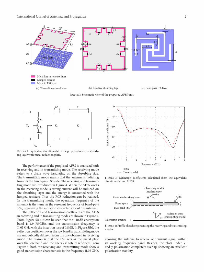
The schematic view of the proposed AFSS unit is shownin Figure 1. It consists of a resistive absorbing layer anda band-pass FSS layer separated by a PMI foam with thepermittivity closed to air and thickness of ℎ = 14mm. Theresistive layer and FSS layer are printed on the substrates withthe permittivity of 2.2 and thickness of 0.254mm. It is worthmentioning that the proposed AFSS gains some advantagesover the AFSS in the existing literatures, such as polarizationstability andwider absorbing band.The design of the resistiveabsorbing layer is introduced as follows.
The square-ring-shaped structure is widely utilized todesign themetamaterial absorber [24–27], and the equivalentcircuit model for arrays of square loops is introduced in[25, 28]. Based on the structure in [25], the structure of
Table 1: Parameters of the proposed AFSS.
Parameter Value(mm)
px 17.2𝐿1 4.7𝐿5 1.7𝑊1 0.4py 17.2𝐿2 1.6𝐿6 2.2𝑊2 0.2ℎ2 0.254𝐿3 1.5𝐿7 1𝑠 0.3ℎ1 14𝐿4 0.7𝐿8 0.4𝑠1 0.25
the resistive layer in the submitted paper is proposed. Themeandering metal lines are designed to realize the minia-turization. The design guidelines of a wideband absorber areintroduced in [26]. Following the steps in [26], the resistivelayer dimensions can be determined.The detailed parametersof the proposed AFSS are presented in Table 1. Besides,resistance 𝑅1 and resistance 𝑅2 in Figure 1 are optimizedfor optimum frequency responses, which are 10Ohms and43Ohms, respectively.
The equivalent circuit model of the proposed resistiveabsorbing layer with metal reflection plate named absorber ispresented in Figure 2. 𝑌0 and 𝑌in are the intrinsic admittanceof air and the input admittance of the absorber, respectively.To verify the validity of the equivalent circuit model, thereflectivity performance of the absorber by the circuit modelagainst HFSS software is compared, illuminated in Figure 3.The circuit model is conducted using the values: 𝑅 = 235Ω,𝐶 = 0.3 pF, and 𝐿 = 7.4 nH. From Figure 3, the resultsbetween the circuit model and HFSS simulations are in goodagreement. And there are two resonances within the operat-ing frequency band. Based on the two resonances, the pro-posed AFSS realizes the wideband absorbing performance.
An important step in the FSS design is the choice ofthe element form, which affects the operating bandwidthand polarization stability of FSS. Generally, various FSScan be applied in the AFSS design if the FSS satisfies twocharacteristics: (1) in the transmission band, the insertionloss of the AFSS should be as small as possible for theeffective transmission of signal; (2) in the absorbing band, thereflection property of the FSS should be as close as possibleto themetal plate.The band-pass FSS element dimensions aredetermined using FSS design theory [29]. Considering theeffect between the absorbing layer and FSS layer, the arrayand spacing of FSS element are optimized to realize the lowerinsertion loss.
International Journal of Antennas and Propagation 3
h1
h2
h2
py
px
PMI foam
Metal line in resistive layer Lumped resistorMetal in FSS layer
(a) Three-dimensional view
s
w1
L2
L1
L4
L3
R1 R1
R1
R1
R2
R2
R2R2
R2
R2 R2
R2
(b) Resistive absorbing layer
s1
L5
L6
L7 L8
W2
(c) Band-pass FSS layer
Figure 1: Schematic view of the proposed AFSS unit.
R
L
C
h1h2
Yin
Y0 Y01Y02
Yd
Figure 2: Equivalent circuit model of the proposed resistive absorb-ing layer with metal reflection plate.
The performance of the proposed AFSS is analyzed bothin receiving and in transmitting mode. The receiving moderefers to a plane wave irradiating on the absorbing side.The transmitting mode means that the antenna is radiatingtowards the band-pass FSS side. The receiving and transmit-ting mode are introduced in Figure 4. When the AFSS worksin the receiving mode, a strong current will be induced onthe absorbing layer and the energy is consumed with thelumped resisters. Thus the RCS reduction can be realized.In the transmitting mode, the operation frequency of theantenna is the same as the resonant frequency of band-passFSS, preserving the radiation characteristics of the antenna.
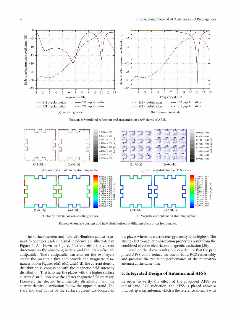
The reflection and transmission coefficients of the AFSSin receiving and in transmitting mode are shown in Figure 5.From Figure 5(a), it can be seen that the −10 dB absorptionband is 1.9–7.5GHz, and the transmission frequency is11.05GHz with the insertion loss of 0.8 dB. In Figure 5(b), thereflection coefficients over the low band in transmittingmodeare undoubtedly different from the one obtained in receivingmode. The reason is that the FSS acts as the metal plateover the low band and the energy is totally reflected. FromFigure 5, both the receiving and transmitting mode show agood transmission characteristic in the frequency 11.05GHz,
HFSSCircuit model
−25
−20
−15
−10
−5
0Re
flect
ion
coeffi
cien
t (dB
)
2 3 4 5 6 7 81Frequency (GHz)
Figure 3: Reflection coefficients calculated from the equivalentcircuit model and HFSS.
Resistive absorbing layer
Pass-band FSSFoam space
AFSS
Incident wave
kE
H
Microstrip antenna
k
EH Radiation wave
(Receiving mode)
(transmitting mode)
Figure 4: Profile sketch representing the receiving and transmittingmodes.
allowing the antenna to receive or transmit signal withinits working frequency band. Besides, the plots under 𝑥-and 𝑦-polarization completely overlap, showing an excellentpolarization stability.
4 International Journal of Antennas and Propagation
S11 x-polarization S21 x-polarization
S11 y-polarization S21 y-polarization
2 3 4 5 6 7 8 9 10 11 12 131Frequency (GHz)
−35
−30
−25
−20
−15
−10
−5
0Re
flect
ion/
tran
smiss
ion
coeffi
cien
t (dB
)
(a) Receiving mode
S22 x-polarization S12 x-polarization
S22 y-polarization S12 y-polarization
2 3 4 5 6 7 8 9 10 11 12 131Frequency (GHz)
−35
−30
−25
−20
−15
−10
−5
0
Refle
ctio
n/tr
ansm
issio
n co
effici
ent (
dB)
(b) Transmitting mode
Figure 5: Simulated reflection and transmission coefficients of AFSS.
0.0000e + 000
1.1429e + 001
2.2857e + 001
3.4286e + 001
4.5714e + 001
5.7143e + 001
6.8571e + 001
8.0000e + 001
Jsur
f [A
_per
_m]
(6.6GHz)(2.4 GHz)
(a) Current distributions on absorbing surface
0.0000e + 000
1.1429e + 001
2.2857e + 001
3.4286e + 001
4.5714e + 001
5.7143e + 001
6.8571e + 001
8.0000e + 001
Jsur
f [A
_per
_m]
(6.6GHz)(2.4GHz)
(b) Current distributions on FSS surface
1.0000e + 0017.2357e + 0021.4371e + 0032.1507e + 0032.8643e + 0033.5779e + 0034.2914e + 0035.0050e + 0035.7186e + 0036.4321e + 003
7.8593e + 0037.1457e + 003
8.5729e + 0039.2864e + 0031.0000e + 004
Efie
ld [V
_per
_m]
(6.6GHz)(2.4GHz)
(c) Electric distributions on absorbing surface
0.0000e + 0007.1429e + 0001.4286e + 0012.1429e + 0012.8571e + 0013.5714e + 0014.2857e + 0015.0000e + 0015.7143e + 0016.4286e + 0017.1429e + 0017.8571e + 0018.5714e + 0019.2857e + 0011.0000e + 002
Hfie
ld [A
_per
_m]
(6.6GHz)(2.4GHz)
(d) Magnetic distributions on absorbing surface
Figure 6: Surface current and field distributions at different absorption frequencies.
The surface current and field distributions at two reso-nant frequencies under normal incidence are illustrated inFigure 6. As shown in Figures 6(a) and 6(b), the currentdirections on the absorbing surface and the FSS surface areantiparallel. These antiparallel currents on the two layerscreate the magnetic flux and provide the magnetic reso-nances. From Figures 6(a), 6(c), and 6(d), the current densitydistribution is consistent with the magnetic field intensitydistribution. That is to say, the places with the higher surfacecurrent distribution have the greater magnetic field intensity.However, the electric field intensity distribution and thecurrent density distribution follow the opposite trend. Thestart and end points of the surface current are located in
the places where the electric energy density is the highest.Thestrong electromagnetic absorption properties result from thecombined effect of electric and magnetic excitation [30].
Based on the above results, one can deduce that the pro-posed AFSS could reduce the out-of-band RCS remarkablyand preserve the radiation performance of the microstripantenna at the same time.
3. Integrated Design of Antenna and AFSS
In order to verify the effect of the proposed AFSS onout-of-band RCS reduction, the AFSS is placed above amicrostrip array antenna, which is the reference antennawith
International Journal of Antennas and Propagation 5
W
L
a
b
dis1
dis2
c4
c2c1
c3
x
y
(a) Reference antenna
PMI foam
Metal line in resistive layer Lumped resistorMetal in FSS layer
Radiation patchGround plate
d1
d2
x
y
(b) Reference antenna with AFSS (Antenna2)
(c) Fabricated reference antenna and reference antenna withAFSS (Antenna2)
Figure 7: Schematic diagrams of reference antenna and integrated design.
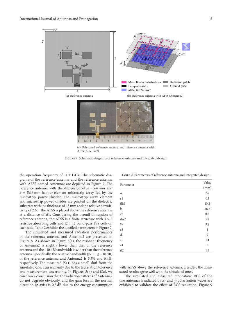
the operation frequency of 11.05GHz. The schematic dia-grams of the reference antenna and the reference antennawith AFSS named Antenna2 are depicted in Figure 7. Thereference antenna with the dimension of 𝑎 = 66mm and𝑏 = 56.6mm is four-element microstrip array fed by themicrostrip power divider. The microstrip array elementand microstrip power divider are printed on the dielectricsubstratewith the thickness of 1.5mmand the relative permit-tivity of 2.65.The AFSS is placed above the reference antennaat a distance of 𝑑1. Considering the overall dimension ofreference antenna, the AFSS is a finite structure with 3 × 3resistive absorbing cells and 12 × 12 band-pass FSS cells oneach side. Table 2 exhibits the detailed parameters in Figure 7.
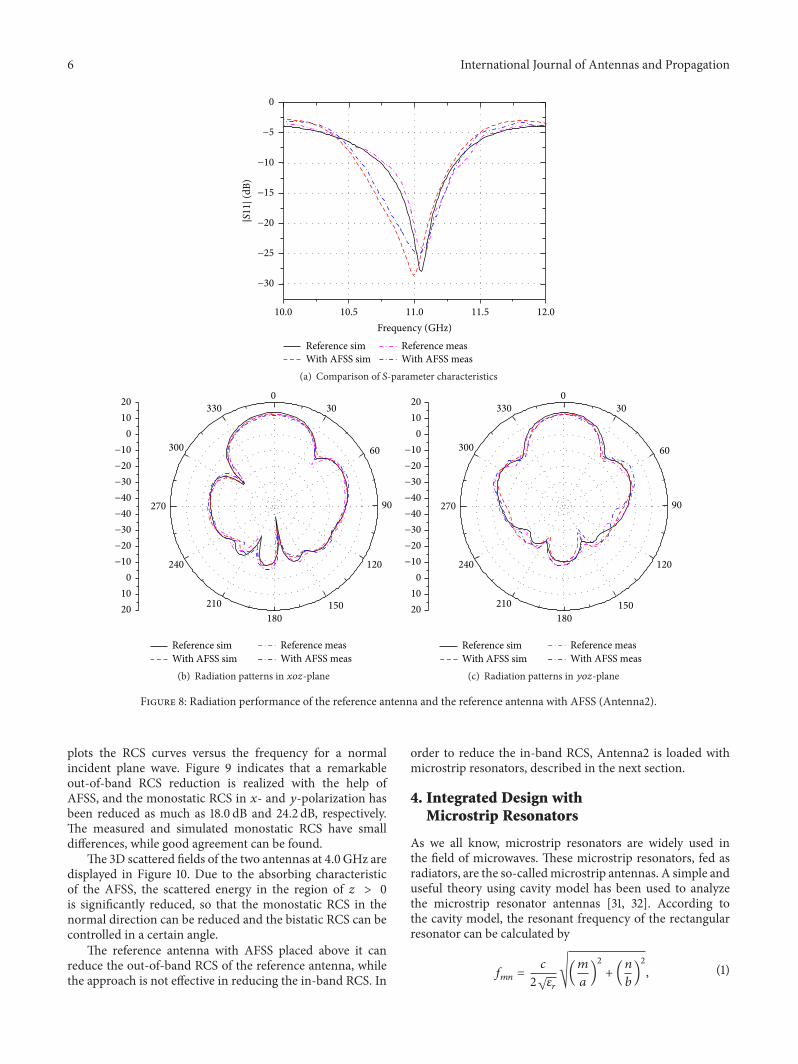
The simulated and measured radiation performancesof the reference antenna and Antenna2 are presented inFigure 8. As shown in Figure 8(a), the resonant frequencyof Antenna2 is slightly lower than that of the referenceantenna and the−10 dB bandwidth is wider than the referenceantenna. Specifically, the relative bandwidth (|𝑆11| ≤ −10 dB)of the reference antenna and Antenna2 is 5.5% and 6.4%,respectively. The measured |𝑆11| has a small shift from thesimulated one.This is mainly due to the fabrication toleranceand measurement uncertainty. In Figures 8(b) and 8(c), wecan draw a conclusion that the radiation patterns of Antenna2do not degrade obviously, and the gain loss in the normaldirection (𝑧-axis) is 0.8 dB due to the energy consumption
Table 2: Parameters of reference antenna and integrated design.
Parameter Value(mm)
𝑎 66𝑐1 0.1dis1 10.2𝑏 56.6𝑐2 0.6dis2 7.8𝑊 9.8𝑐3 1𝑑1 9𝐿 7.4𝑐4 5𝑑2 1.5
with AFSS above the reference antenna. Besides, the mea-sured results agree well with the simulated ones.
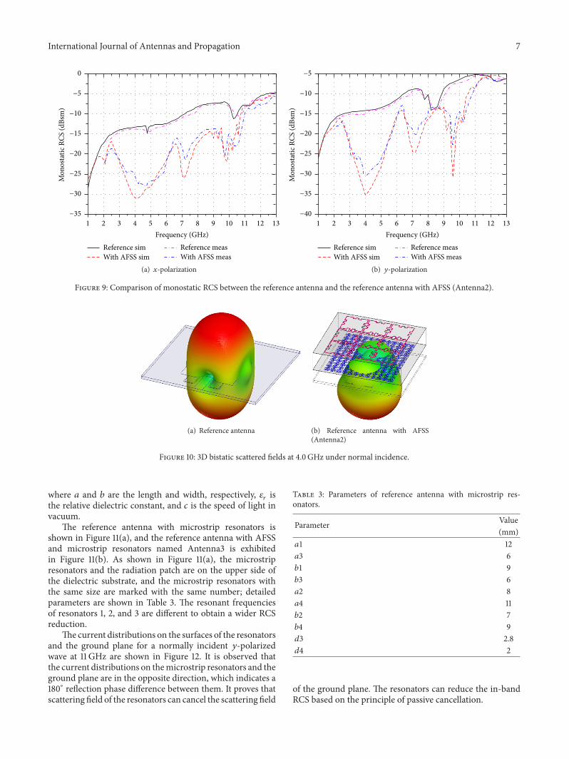
The simulated and measured monostatic RCS of thetwo antennas irradiated by 𝑥- and 𝑦-polarization waves areexhibited to validate the effect of RCS reduction. Figure 9
6 International Journal of Antennas and Propagation
Reference simWith AFSS sim
Reference measWith AFSS meas
−30
−25
−20|S11|
(dB)
−15
−10
−5
0
10.5 11.0 11.5 12.010.0Frequency (GHz)
(a) Comparison of 𝑆-parameter characteristics
030
60
90
120
150180
210
240
270
300
330
Reference simWith AFSS sim
Reference measWith AFSS meas
2010
0−10−20−30−40−40−30−20−10
01020
(b) Radiation patterns in 𝑥𝑜𝑧-plane
030
60
90
120
150180
210
240
270
300
330
Reference simWith AFSS sim
Reference measWith AFSS meas
2010
0−10−20−30−40−40−30−20−10
01020
(c) Radiation patterns in 𝑦𝑜𝑧-plane
Figure 8: Radiation performance of the reference antenna and the reference antenna with AFSS (Antenna2).
plots the RCS curves versus the frequency for a normalincident plane wave. Figure 9 indicates that a remarkableout-of-band RCS reduction is realized with the help ofAFSS, and the monostatic RCS in 𝑥- and 𝑦-polarization hasbeen reduced as much as 18.0 dB and 24.2 dB, respectively.The measured and simulated monostatic RCS have smalldifferences, while good agreement can be found.
The 3D scattered fields of the two antennas at 4.0GHz aredisplayed in Figure 10. Due to the absorbing characteristicof the AFSS, the scattered energy in the region of 𝑧 > 0is significantly reduced, so that the monostatic RCS in thenormal direction can be reduced and the bistatic RCS can becontrolled in a certain angle.
The reference antenna with AFSS placed above it canreduce the out-of-band RCS of the reference antenna, whilethe approach is not effective in reducing the in-band RCS. In
order to reduce the in-band RCS, Antenna2 is loaded withmicrostrip resonators, described in the next section.
4. Integrated Design withMicrostrip Resonators
As we all know, microstrip resonators are widely used inthe field of microwaves. These microstrip resonators, fed asradiators, are the so-calledmicrostrip antennas. A simple anduseful theory using cavity model has been used to analyzethe microstrip resonator antennas [31, 32]. According tothe cavity model, the resonant frequency of the rectangularresonator can be calculated by
𝑓𝑚𝑛 = 𝑐2√𝜀𝑟√(𝑚𝑎 )2 + (𝑛𝑏)
2, (1)
International Journal of Antennas and Propagation 7
2 3 4 5 6 7 8 9 10 11 12 131Frequency (GHz)
−35
−30
−25
−20
−15
−10
−5
0M
onos
tatic
RCS
(dBs
m)
Reference simWith AFSS sim
Reference measWith AFSS meas
(a) 𝑥-polarization
2 3 4 5 6 7 8 9 10 11 12 131Frequency (GHz)
Reference simWith AFSS sim
Reference measWith AFSS meas
−40
−35
−30
−25
−20
−15
−10
Mon
osta
tic R
CS (d
Bsm
)
−5
(b) 𝑦-polarization
Figure 9: Comparison of monostatic RCS between the reference antenna and the reference antenna with AFSS (Antenna2).
(a) Reference antenna (b) Reference antenna with AFSS(Antenna2)
Figure 10: 3D bistatic scattered fields at 4.0GHz under normal incidence.
where 𝑎 and 𝑏 are the length and width, respectively, 𝜀𝑟 isthe relative dielectric constant, and 𝑐 is the speed of light invacuum.
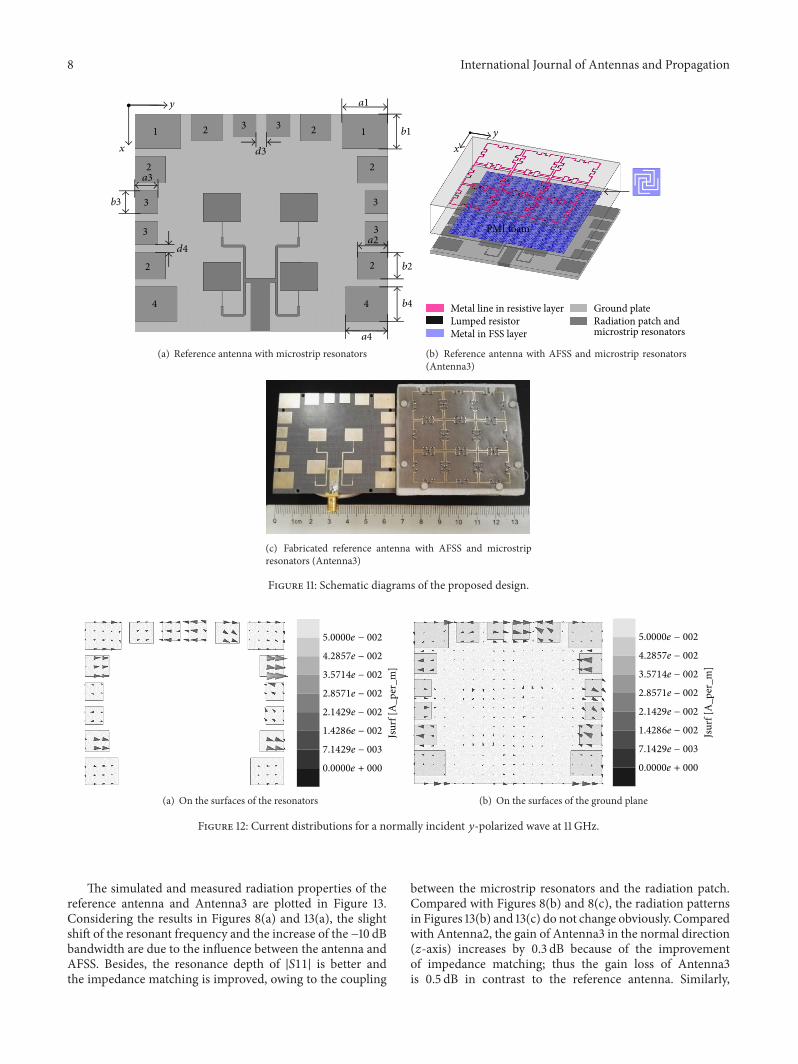
The reference antenna with microstrip resonators isshown in Figure 11(a), and the reference antenna with AFSSand microstrip resonators named Antenna3 is exhibitedin Figure 11(b). As shown in Figure 11(a), the microstripresonators and the radiation patch are on the upper side ofthe dielectric substrate, and the microstrip resonators withthe same size are marked with the same number; detailedparameters are shown in Table 3. The resonant frequenciesof resonators 1, 2, and 3 are different to obtain a wider RCSreduction.
The current distributions on the surfaces of the resonatorsand the ground plane for a normally incident 𝑦-polarizedwave at 11 GHz are shown in Figure 12. It is observed thatthe current distributions on themicrostrip resonators and theground plane are in the opposite direction, which indicates a180∘ reflection phase difference between them. It proves thatscattering field of the resonators can cancel the scattering field
Table 3: Parameters of reference antenna with microstrip res-onators.
Parameter Value(mm)
𝑎1 12𝑎3 6𝑏1 9𝑏3 6𝑎2 8𝑎4 11𝑏2 7𝑏4 9𝑑3 2.8𝑑4 2
of the ground plane. The resonators can reduce the in-bandRCS based on the principle of passive cancellation.
8 International Journal of Antennas and Propagation
1
a1
b112 2
2
2
2
2
a2
b2
3 3
3
3
3
3
a3
b3
4 4
a4
b4
d3
d4
x
y
(a) Reference antenna with microstrip resonators
PMI foam
Metal line in resistive layer Lumped resistorMetal in FSS layer
Ground plate
x
y
Radiation patch and microstrip resonators
(b) Reference antenna with AFSS and microstrip resonators(Antenna3)
(c) Fabricated reference antenna with AFSS and microstripresonators (Antenna3)
Figure 11: Schematic diagrams of the proposed design.
0.0000e + 000
7.1429e − 003
1.4286e − 002
2.1429e − 002
2.8571e − 002
3.5714e − 002
4.2857e − 002
5.0000e − 002
Jsur
f [A
_per
_m]
(a) On the surfaces of the resonators
0.0000e + 000
7.1429e − 003
1.4286e − 002
2.1429e − 002
2.8571e − 002
3.5714e − 002
4.2857e − 002
5.0000e − 002
Jsur
f [A
_per
_m]
(b) On the surfaces of the ground plane
Figure 12: Current distributions for a normally incident 𝑦-polarized wave at 11 GHz.
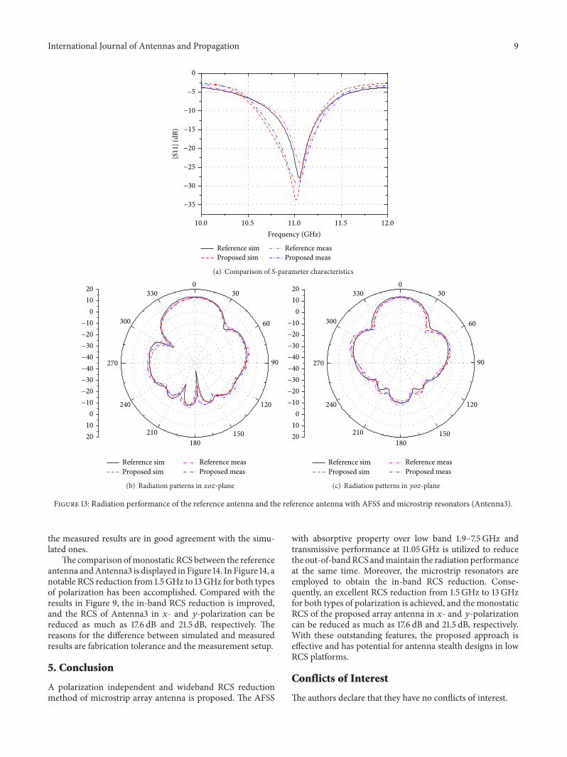
The simulated and measured radiation properties of thereference antenna and Antenna3 are plotted in Figure 13.Considering the results in Figures 8(a) and 13(a), the slightshift of the resonant frequency and the increase of the −10 dBbandwidth are due to the influence between the antenna andAFSS. Besides, the resonance depth of |𝑆11| is better andthe impedance matching is improved, owing to the coupling
between the microstrip resonators and the radiation patch.Compared with Figures 8(b) and 8(c), the radiation patternsin Figures 13(b) and 13(c) do not change obviously. Comparedwith Antenna2, the gain of Antenna3 in the normal direction(𝑧-axis) increases by 0.3 dB because of the improvementof impedance matching; thus the gain loss of Antenna3is 0.5 dB in contrast to the reference antenna. Similarly,
International Journal of Antennas and Propagation 9
Reference sim Reference meas
−35
−30
−25
−20
|S11|
(dB) −15
−10
−5
0
10.5 11.0 11.5 12.010.0Frequency (GHz)
Proposed sim Proposed meas
(a) Comparison of 𝑆-parameter characteristics
030
60
90
120
150180
210
240
270
300
330
Reference simProposed sim
Reference measProposed meas
2010
0−10−20−30−40−40−30−20−10
01020
(b) Radiation patterns in 𝑥𝑜𝑧-plane
030
60
90
120
150180
210
240
270
300
330
Reference simProposed sim
Reference measProposed meas
2010
0−10−20−30−40−40−30−20−10
01020
(c) Radiation patterns in 𝑦𝑜𝑧-plane
Figure 13: Radiation performance of the reference antenna and the reference antenna with AFSS and microstrip resonators (Antenna3).
the measured results are in good agreement with the simu-lated ones.
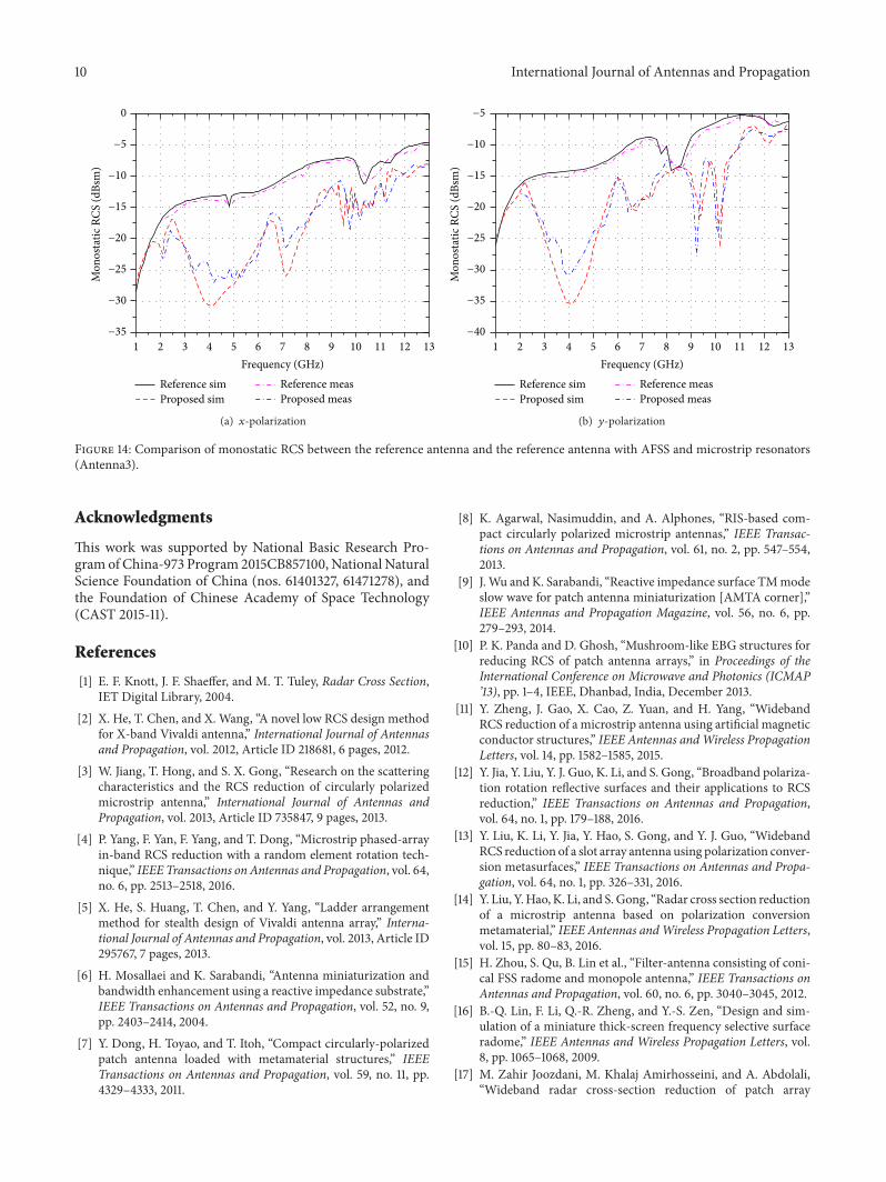
The comparison ofmonostatic RCS between the referenceantenna andAntenna3 is displayed in Figure 14. In Figure 14, anotable RCS reduction from 1.5GHz to 13GHz for both typesof polarization has been accomplished. Compared with theresults in Figure 9, the in-band RCS reduction is improved,and the RCS of Antenna3 in 𝑥- and 𝑦-polarization can bereduced as much as 17.6 dB and 21.5 dB, respectively. Thereasons for the difference between simulated and measuredresults are fabrication tolerance and the measurement setup.
5. Conclusion
A polarization independent and wideband RCS reductionmethod of microstrip array antenna is proposed. The AFSS
with absorptive property over low band 1.9–7.5GHz andtransmissive performance at 11.05GHz is utilized to reducethe out-of-bandRCS andmaintain the radiation performanceat the same time. Moreover, the microstrip resonators areemployed to obtain the in-band RCS reduction. Conse-quently, an excellent RCS reduction from 1.5GHz to 13GHzfor both types of polarization is achieved, and the monostaticRCS of the proposed array antenna in 𝑥- and 𝑦-polarizationcan be reduced as much as 17.6 dB and 21.5 dB, respectively.With these outstanding features, the proposed approach iseffective and has potential for antenna stealth designs in lowRCS platforms.
Conflicts of Interest
The authors declare that they have no conflicts of interest.
10 International Journal of Antennas and Propagation
2 3 4 5 6 7 8 9 10 11 12 131Frequency (GHz)
−35
−30
−25
−20
−15
−10
−5
0M
onos
tatic
RCS
(dBs
m)
Reference sim Reference measProposed sim Proposed meas
(a) 𝑥-polarization
2 3 4 5 6 7 8 9 10 11 12 131Frequency (GHz)
−40
−35
−30
−25
−20
−15
−10
−5
Mon
osta
tic R
CS (d
Bsm
)
Reference sim Reference measProposed sim Proposed meas
(b) 𝑦-polarization
Figure 14: Comparison of monostatic RCS between the reference antenna and the reference antenna with AFSS and microstrip resonators(Antenna3).
Acknowledgments
This work was supported by National Basic Research Pro-gram of China-973 Program 2015CB857100, National NaturalScience Foundation of China (nos. 61401327, 61471278), andthe Foundation of Chinese Academy of Space Technology(CAST 2015-11).
References
[1] E. F. Knott, J. F. Shaeffer, and M. T. Tuley, Radar Cross Section,IET Digital Library, 2004.
[2] X. He, T. Chen, and X. Wang, “A novel low RCS design methodfor X-band Vivaldi antenna,” International Journal of Antennasand Propagation, vol. 2012, Article ID 218681, 6 pages, 2012.
[3] W. Jiang, T. Hong, and S. X. Gong, “Research on the scatteringcharacteristics and the RCS reduction of circularly polarizedmicrostrip antenna,” International Journal of Antennas andPropagation, vol. 2013, Article ID 735847, 9 pages, 2013.
[4] P. Yang, F. Yan, F. Yang, and T. Dong, “Microstrip phased-arrayin-band RCS reduction with a random element rotation tech-nique,” IEEE Transactions on Antennas and Propagation, vol. 64,no. 6, pp. 2513–2518, 2016.
[5] X. He, S. Huang, T. Chen, and Y. Yang, “Ladder arrangementmethod for stealth design of Vivaldi antenna array,” Interna-tional Journal of Antennas and Propagation, vol. 2013, Article ID295767, 7 pages, 2013.
[6] H. Mosallaei and K. Sarabandi, “Antenna miniaturization andbandwidth enhancement using a reactive impedance substrate,”IEEE Transactions on Antennas and Propagation, vol. 52, no. 9,pp. 2403–2414, 2004.
[7] Y. Dong, H. Toyao, and T. Itoh, “Compact circularly-polarizedpatch antenna loaded with metamaterial structures,” IEEETransactions on Antennas and Propagation, vol. 59, no. 11, pp.4329–4333, 2011.
[8] K. Agarwal, Nasimuddin, and A. Alphones, “RIS-based com-pact circularly polarized microstrip antennas,” IEEE Transac-tions on Antennas and Propagation, vol. 61, no. 2, pp. 547–554,2013.
[9] J.Wu and K. Sarabandi, “Reactive impedance surface TMmodeslow wave for patch antenna miniaturization [AMTA corner],”IEEE Antennas and Propagation Magazine, vol. 56, no. 6, pp.279–293, 2014.
[10] P. K. Panda and D. Ghosh, “Mushroom-like EBG structures forreducing RCS of patch antenna arrays,” in Proceedings of theInternational Conference on Microwave and Photonics (ICMAP’13), pp. 1–4, IEEE, Dhanbad, India, December 2013.
[11] Y. Zheng, J. Gao, X. Cao, Z. Yuan, and H. Yang, “WidebandRCS reduction of a microstrip antenna using artificial magneticconductor structures,” IEEE Antennas andWireless PropagationLetters, vol. 14, pp. 1582–1585, 2015.
[12] Y. Jia, Y. Liu, Y. J. Guo, K. Li, and S. Gong, “Broadband polariza-tion rotation reflective surfaces and their applications to RCSreduction,” IEEE Transactions on Antennas and Propagation,vol. 64, no. 1, pp. 179–188, 2016.
[13] Y. Liu, K. Li, Y. Jia, Y. Hao, S. Gong, and Y. J. Guo, “WidebandRCS reduction of a slot array antenna using polarization conver-sion metasurfaces,” IEEE Transactions on Antennas and Propa-gation, vol. 64, no. 1, pp. 326–331, 2016.
[14] Y. Liu, Y.Hao, K. Li, and S.Gong, “Radar cross section reductionof a microstrip antenna based on polarization conversionmetamaterial,” IEEE Antennas andWireless Propagation Letters,vol. 15, pp. 80–83, 2016.
[15] H. Zhou, S. Qu, B. Lin et al., “Filter-antenna consisting of coni-cal FSS radome and monopole antenna,” IEEE Transactions onAntennas and Propagation, vol. 60, no. 6, pp. 3040–3045, 2012.
[16] B.-Q. Lin, F. Li, Q.-R. Zheng, and Y.-S. Zen, “Design and sim-ulation of a miniature thick-screen frequency selective surfaceradome,” IEEE Antennas and Wireless Propagation Letters, vol.8, pp. 1065–1068, 2009.
[17] M. Zahir Joozdani, M. Khalaj Amirhosseini, and A. Abdolali,“Wideband radar cross-section reduction of patch array
International Journal of Antennas and Propagation 11
antenna with miniaturised hexagonal loop frequency selectivesurface,” Electronics Letters, vol. 52, no. 9, pp. 767–768, 2016.
[18] W. S. Arceneaux, R. D. Akins, andW. B.May, “Absorptive/trans-missive radome,” US Patent 5,400,043, 1995.
[19] Q. Chen, J. Bai, L. Chen, and Y. Fu, “A miniaturized absorptivefrequency selective surface,” IEEE Antennas and Wireless Prop-agation Letters, vol. 14, pp. 80–83, 2015.
[20] B. Yi, P. Liu, G. Li, and Y. Dong, “Design of miniaturizedand ultrathin absorptive/transmissive radome with widebandabsorbing property,”Microwave and Optical Technology Letters,vol. 58, no. 8, pp. 1870–1875, 2016.
[21] Q. Chen, L. Chen, J. Bai, and Y. Fu, “Design of absorptivefrequency selective surface with good transmission at highfrequency,” Electronics Letters, vol. 51, no. 12, pp. 885–886, 2015.
[22] Q. Chen, L. Liu, L. Chen, J. Bai, andY. Fu, “Absorptive frequencyselective surface using parallel LC resonance,” Electronics Let-ters, vol. 52, no. 6, pp. 418–419, 2016.
[23] Q. Chen and Y. Fu, “A planar stealthy antenna radome usingabsorptive frequency selective surface,”Microwave and OpticalTechnology Letters, vol. 56, no. 8, pp. 1788–1792, 2014.
[24] C. Huang, W. Pan, X. Ma, and X. Luo, “Wideband radar cross-section reduction of a stacked patch array antenna using meta-surface,” IEEE Antennas and Wireless Propagation Letters, vol.14, pp. 1369–1372, 2015.
[25] S. Ghosh, S. Bhattacharyya, and K. V. Srivastava, “Design andanalysis of a broadband single layer circuit analog absorber,” inProceedings of the 46th EuropeanMicrowave Conference (EuMC’16), pp. 584–587, London, UK, October 2016.
[26] Y. Shang, Z. Shen, and S. Xiao, “On the design of single-layercircuit analog absorber using double-square-loop array,” IEEETransactions on Antennas and Propagation, vol. 61, no. 12, pp.6022–6029, 2013.
[27] J. Yang and Z. Shen, “A thin and broadband absorber usingdouble-square loops,” IEEE Antennas and Wireless PropagationLetters, vol. 6, pp. 388–391, 2007.
[28] R. J. Langley and E. A. Parker, “Equivalent circuit model forarrays of square loops,” Electronics Letters, vol. 18, no. 7, pp. 294–296, 1982.
[29] B. A. Munk, Frequency Selective Surfaces: Theory and Design,John Wiley & Sons, New York, NY, USA, 2000.
[30] X. Shen, T. J. Cui, J. Zhao, H. F. Ma, W. X. Jiang, and H. Li,“Polarization-independent wide-angle triple-band metamate-rial absorber,”Optics Express, vol. 19, no. 10, pp. 9401–9407, 2011.
[31] A. G. Derneryd and A. G. Lind, “Extended analysis of rect-angular microstrip resonator antennas,” IEEE Transactions onAntennas and Propagation, vol. 27, no. 6, pp. 846–849, 1979.
[32] I. Wolff and N. Knoppik, “Rectangular and circular microstripdisk capacitors and resonators,” IEEE Transactions on Micro-wave Theory and Techniques, vol. 22, no. 10, pp. 857–864, 1974.

RoboticsJournal of
Hindawi Publishing Corporationhttp://www.hindawi.com Volume 2014
Hindawi Publishing Corporationhttp://www.hindawi.com Volume 2014
Active and Passive Electronic Components
Control Scienceand Engineering
Journal of
Hindawi Publishing Corporationhttp://www.hindawi.com Volume 2014
International Journal of
RotatingMachinery
Hindawi Publishing Corporationhttp://www.hindawi.com Volume 2014
Hindawi Publishing Corporation http://www.hindawi.com
Journal of
Volume 201
Submit your manuscripts athttps://www.hindawi.com
VLSI Design
Hindawi Publishing Corporationhttp://www.hindawi.com Volume 201
Hindawi Publishing Corporationhttp://www.hindawi.com Volume 2014
Shock and Vibration
Hindawi Publishing Corporationhttp://www.hindawi.com Volume 2014
Civil EngineeringAdvances in
Acoustics and VibrationAdvances in
Hindawi Publishing Corporationhttp://www.hindawi.com Volume 2014
Hindawi Publishing Corporationhttp://www.hindawi.com Volume 2014
Electrical and Computer Engineering
Journal of
Advances inOptoElectronics
Hindawi Publishing Corporation http://www.hindawi.com
Volume 2014
The Scientific World JournalHindawi Publishing Corporation http://www.hindawi.com Volume 2014
SensorsJournal of
Hindawi Publishing Corporationhttp://www.hindawi.com Volume 2014
Modelling & Simulation in EngineeringHindawi Publishing Corporation http://www.hindawi.com Volume 2014
Hindawi Publishing Corporationhttp://www.hindawi.com Volume 2014
Chemical EngineeringInternational Journal of Antennas and
Propagation
International Journal of
Hindawi Publishing Corporationhttp://www.hindawi.com Volume 2014
Hindawi Publishing Corporationhttp://www.hindawi.com Volume 2014
Navigation and Observation
International Journal of
Hindawi Publishing Corporationhttp://www.hindawi.com Volume 2014
DistributedSensor Networks
International Journal of