Embed Size (px)
Citation preview
7750 SR Triple Play Service Delivery Architecture Page 1823
WIFI Aggregation and Offload
In This Section
This section describes features and functionality for 7750 SR to act as a WLAN-GW providing
subscriber management (ESM), mobility and 3G/4G interworking functions for WIFI subscribers
gaining access from WLANs in hot-spots and home-spots.
Topics in this section include:
• WIFI Aggregation and Offload Overview on page 1824
• Layer 2 over Soft-GRE Tunnels on page 1826
• Tunnel Level Egress QoS on page 1832
• Authentication on page 1840
• Address Assignment on page 1850
• WIFI Mobility Anchor on page 1852
• Wholesale on page 1853
• CGN on WLAN-GW on page 1854
• Lawful Intercept on WLAN-GW on page 1855
• WIFI Offload – 3G/4G Interworking on page 1860
• Migrant User Support on page 1875
• Layer 2 Wholesale on page 1911
• Distributed Subscriber Management (DSM) on page 1882
• Distributed RADIUS Proxy on page 1895
• IPv6-only Access on page 1905
• Layer 2 Wholesale on page 1911
• VLAN to WLAN-GW IOM/IMM Steering via Internal Epipe on page 1912
WIFI Aggregation and Offload Overview
Page 1824 7750 SR Triple Play Service Delivery Architecture
WIFI Aggregation and Offload Overview
This solution set adds support for managing subscribers gaining network access over WLAN. The
WLAN access enables a service provider to offer a mobile broadband service to its subscribers or
to offload traffic on its or a partners macro cellular (3G/4G) network. The WLAN access can be
from public hot-spots (indoor or outdoor APs), venues, enterprises, or home-spots (with public
SSID).
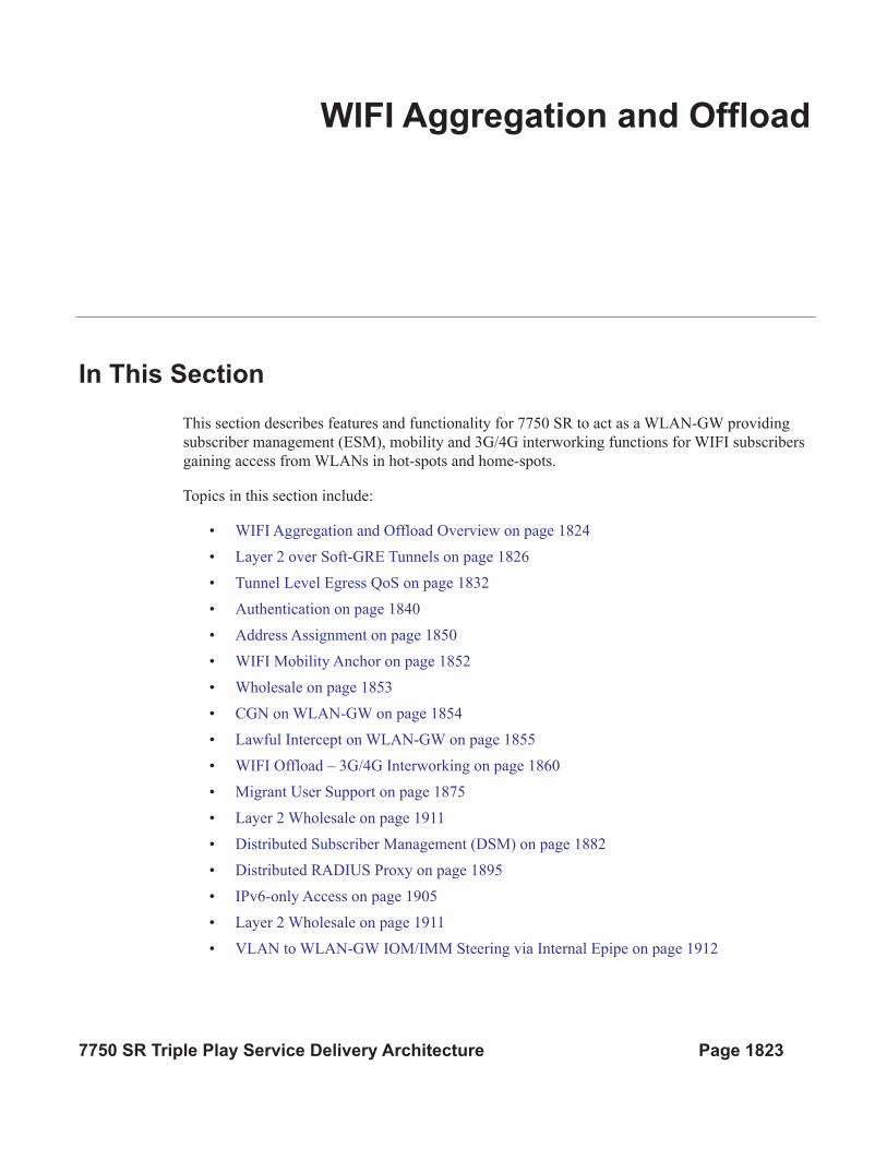
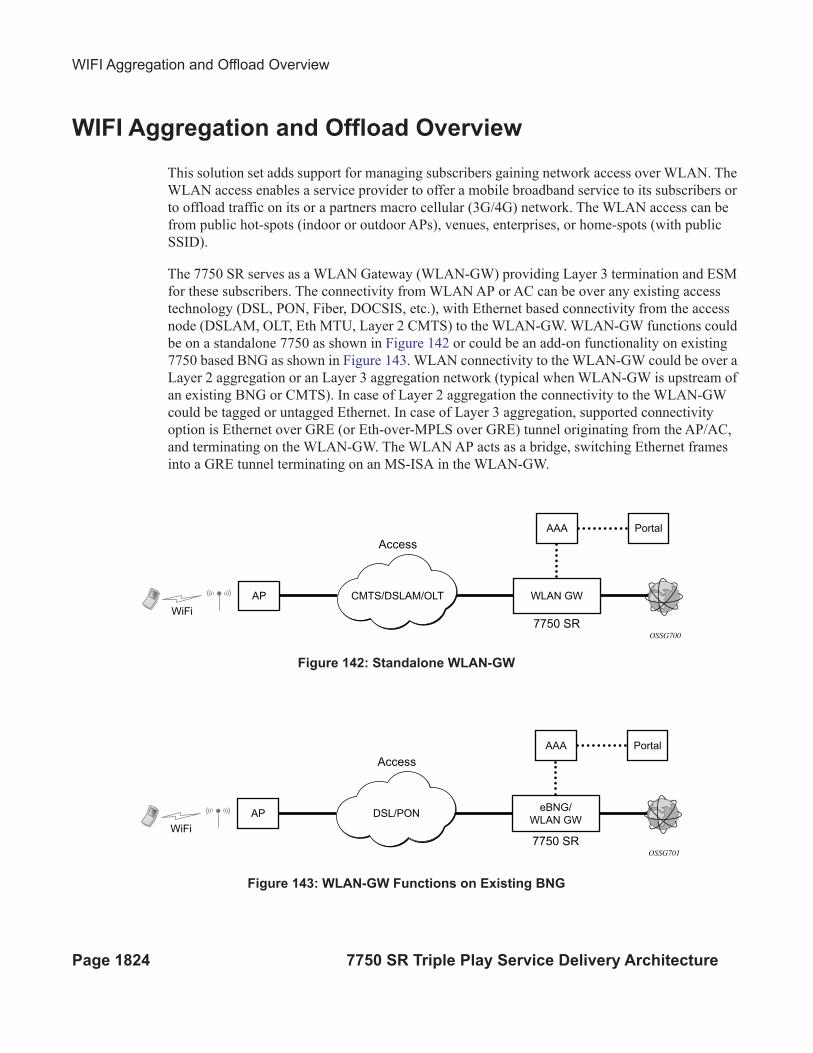
The 7750 SR serves as a WLAN Gateway (WLAN-GW) providing Layer 3 termination and ESM
for these subscribers. The connectivity from WLAN AP or AC can be over any existing access
technology (DSL, PON, Fiber, DOCSIS, etc.), with Ethernet based connectivity from the access
node (DSLAM, OLT, Eth MTU, Layer 2 CMTS) to the WLAN-GW. WLAN-GW functions could
be on a standalone 7750 as shown in Figure 142 or could be an add-on functionality on existing
7750 based BNG as shown in Figure 143. WLAN connectivity to the WLAN-GW could be over a
Layer 2 aggregation or an Layer 3 aggregation network (typical when WLAN-GW is upstream of
an existing BNG or CMTS). In case of Layer 2 aggregation the connectivity to the WLAN-GW
could be tagged or untagged Ethernet. In case of Layer 3 aggregation, supported connectivity
option is Ethernet over GRE (or Eth-over-MPLS over GRE) tunnel originating from the AP/AC,
and terminating on the WLAN-GW. The WLAN AP acts as a bridge, switching Ethernet frames
into a GRE tunnel terminating on an MS-ISA in the WLAN-GW.
Figure 142: Standalone WLAN-GW
Figure 143: WLAN-GW Functions on Existing BNG
OSSG700
AP
AAA Portal
CMTS/DSLAM/OLT WLAN GW
7750 SR
WiFi
Access
OSSG701
AP
WiFi
AAA Portal
DSL/PONeBNG/
WLAN GW
7750 SR
Access
WLAN GW For Mobile Data Offload
7750 SR Triple Play Service Delivery Architecture Page 1825
AP Connectivity to the WLAN-GW could be direct Ethernet (tagged or untagged) or could be
Ethernet over GRE. In future releases, other tunnels encapsulations will be considered. With the
bridged AP using GRE tunnels, the WLAN-GW solution elements are discussed in the following
sections.
Layer 2 over Soft-GRE Tunnels
Page 1826 7750 SR Triple Play Service Delivery Architecture
Layer 2 over Soft-GRE Tunnels
Soft-GRE refers to stateless GRE tunneling, whereby the AP forwards GRE encapsulated traffic to
the WLAN-GW, and the GW reflects back the encapsulation in the downstream traffic towards the
AP. WLAN-GW does not require any per-AP end-point IP address configuration. The WLAN-
GW learns the encapsulation as part of creating the subscriber state on processing the encapsulated
control and data traffic. Following are some of the advantages of soft-GRE:
• Resources are only consumed on the WLAN-GW if there is one or more active subscriber
on the AP. Merely broadcasting an SSID from an AP does not result in any state on the
WLAN-GW.
• No per-AP tunnel end-point configuration on WLAN-GW. This is important as the AP
can get renumbered.
• No control protocol to setup and maintain tunnel state on WLAN-GW.
Soft-GRE tunnel termination is performed on dedicated IOMs with MS-ISAs (referred to as
WLAN-GW IOM) Each slot requires two MS-ISAs dedicated for soft-GRE tunnel termination.
MS-ISA provides tunnel encapsulation/de-capsulation, bandwidth shaping per tunnel (or per-
tunnel per SSID), and anchor point for inter-AP mobility. The ESM function such as per-
subscriber anti-spoofing (IP and MAC), filters, hierarchical policing, and lawful intercept are
provided on the carrier IOM corresponding to the ISA where the subscriber is anchored.
In future releases, other tunnels encapsulations will be considered.
Encapsulation
The GRE encapsulation is based on RFC 1701/2784, Generic Routing Encapsulation (GRE),
WLAN-GW will encapsulate according to RFC 1701 with all the flag fields set to 0, and no
optional fields present. WLAN-GW is able to receive both encapsulation specified in RFC 1701
and RFC 2784, with all flag fields set to 0, and no optional fields present in the header.
WLAN GW For Mobile Data Offload
7750 SR Triple Play Service Delivery Architecture Page 1827
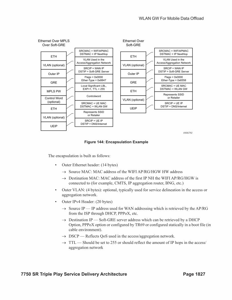
Figure 144: Encapsulation Example
The encapsulation is built as follows:
• Outer Ethernet header: (14 bytes)
→ Source MAC: MAC address of the WIFI AP/RG/HGW HW address
→ Destination MAC: MAC address of the first IP NH the WIFI AP/RG/HGW is
connected to (for example, CMTS, IP aggregation router, BNG, etc.)
• Outer VLAN: (4 bytes): optional, typically used for service delineation in the access or
aggregation network.
• Outer IPv4 Header: (20 bytes)
→ Source IP — IP address used for WAN addressing which is retrieved by the AP/RG
from the ISP through DHCP, PPPoX, etc.
→ Destination IP — Soft-GRE server address which can be retrieved by a DHCP
Option, PPPoX option or configured by TR69 or configured statically in a boot file (in
cable environment).
→ DSCP — Reflects QoS used in the access/aggregation network.
→ TTL — Should be set to 255 or should reflect the amount of IP hops in the access/
aggregation network
ETH
SRCMAC = WIFIAPMAC
DSTMAC = IP NextHop
SRCMAC = UE MAC
DSTMAC = WLAN GW
SRCIP = WAN IP
DSTIP = Soft-GRE Server
SRCIP = UE IP
DSTIP = DNS/Internet
Flags = 0x0000
Ether-Type = 0x8847
Local Significant LBL,
EXP=1, TTL = 255
Controlword
Represents SSID
or Retailer
SRCMAC = UE MAC
DSTMAC = WLAN GW
SRCIP = UE IP
DSTIP = DNS/Internet
Represents SSID
or Retailer
VLAN Used in the
Access/Aggregation Network
SRCMAC = WIFIAPMAC
DSTMAC = IP NextHop
SRCIP = WAN IP
DSTIP = Soft-GRE Server
Flags = 0x0000
Ether-Type = 0x6558
VLAN Used in the
Access/Aggregation NetworkVLAN (optional)
Outer IP
ETH
VLAN (optional)
UEIP
GRE
MPLS PW
Control Word
(optional)
Ethernet Over MPLS
Over Soft-GRE
ETH
VLAN (optional)
Outer IP
ETH
VLAN (optional)
UEIP
GRE
Ethernet Over
Soft-GRE
OSSG702
Encapsulation
Page 1828 7750 SR Triple Play Service Delivery Architecture
• GRE: (4 bytes)
→ All flags are set to 0, such as checksum, sequence number and keys are not present.
→ The Ether-Type is set to 0x6558 for native Ethernet is used, and 0x8847 when MPLS
encapsulation is used.
• MPLS Pseudowire Label (4 bytes)
→ Label Value, statically assigned in the WiFi AP/Controller and reflected back from the
soft-GRE server to the WIFI AP/Controller. The Label is unique within the context of
the source IP address of the tunnel.
→ EXP: 0 (not used)
→ TTL: 255 (not used)
• Inner Ethernet header: (14 bytes)
→ Source MAC: MAC address of the UE
→ Destination MAC: MAC address of the soft-GRE server/WLAN-GW.
• Inner VLAN: (4 bytes): optional, inserted by AP/RG per unique SSID (typically, when the
AP is providing SSID per retailer). WLAN-GW allows mapping the VLAN to a service
context per retailer, in the data plane.
• Inner IPv4 Header: (20 bytes)
→ Source IP: Client’s IP address obtained via DHCP (tunneled).
→ Destination IP: IP address of the destination client trying to reach.
→ DSCP: set by the client/application
→ TTL: set by the client/application
Soft-GRE tunnel termination is performed on dedicated IOMs with MS-ISAs (referred to as
WLAN-GW IOM). Each WLAN-GW IOM requires both MS-ISAs to be plugged in for soft-GRE
tunnel termination. MS-ISA provides tunnel encapsulation/de-capsulation and anchor point for
inter-AP mobility. The carrier IOMs of the ISA where the tunnel is terminated performs
bandwidth shaping per tunnel (or per-tunnel per SSID). ESM function such as per-subscriber anti-
spoofing (IP and MAC), filters, hierarchical policing, and lawful intercept are provided on the
carrier IOM corresponding to the ISA where the subscriber is anchored.
N:M warm standby redundancy is supported for WLAN-GW IOM slots. Up to 4 WLAN-GW
IOMs can be configured per 7750. A maximum 3 WLAN-GW IOMs can be active. One or more
WLAN-GW group can be configured with set of WLAN-GW IOMs, and a limit of active IOMs.
Incoming soft-GRE tunnel contexts and corresponding subscribers are load-balanced amongst the
MS-ISAs on active IOMs. Tunnel load-balancing is based on outer source IP address of the tunnel.
Subscriber load-balancing is based on UE’s MAC address in the source MAC of the Ethernet
payload in the tunnel. IOM(s) beyond the active limit act as warm standby, and take over the
tunnel termination and subscriber management functions from failed WLAN-GW slot.MS-ISAs
on WLAN-GW IOMs can also be configured to perform NAT function.
WLAN GW For Mobile Data Offload
7750 SR Triple Play Service Delivery Architecture Page 1829
config isa wlan-gw-group <group-id>
[no] active-iom-limit <number>
[no] description <description-string>
[no] distributed-sub-mgmt
[no] isa-aa-group <aa-group-id>
[no] * iom <slot-number>
nat
[no] radius-accounting-policy <nat-accounting-policy>
[no] session-limits
[no] reserved <num-sessions>
[no] watermarks high <percentage> low <percentage>
[no] shutdown
An ESM and soft-gre configuration is required for wlan-gw functions. Subscriber and group
interfaces are configured as part of normal ESM configuration. The group interface is enabled for
wlan-gw by configuration. L2oGRE is the currently supported soft tunnel types. The wlan-gw
related configuration includes the following:
• Tunnel end-point IP address.
• Service context for tunnel termination.
• TCP MSS segment size. This is set in TCP SYN and SYN-ACKs by wlan-gw to adjust to
the MTU on access/aggregation network in order to prevent fragmentation of upstream
and downstream TCP packets.
• Mobility related configuration, including mobility trigger packet types (normal data or
special Ethernet IAPP fame), and hold-down time between successive mobility triggers.
• VLAN to retailer mapping. The AP typically inserts a unique dot1Q tag per retail service
provider in the Ethernet payload. The mapping of dot1Q tag to retail service context is
configured under wlan-gw tunnel. The subscriber is then created in the configured retail
service context. The retail service context can also be provided by AAA server in
authentication-accept message based on subscriber credentials or SSID information
contained in DHCP Option82.
• Egress QoS configuration for downstream traffic entering the wlan-gw module for tunnel
encapsulation. This includes type of aggregate bandwidth shaping (per-tunnel or per-
retailer), aggregate-rate-limit, egress QoS policy and scheduler policy. The tunnel shaping
can be configured to be applied only when there is more than one subscriber on the tunnel.
By default the shaping if configured is applied when first subscriber on the tunnel logs in.
*B:Dut-C>config>service>vprn>sub-if>grp-if>wlan-gw# info detail
----------------------------------------------
authentication
no authentication-policy
hold-time sec 5
exit
no data-triggered-ue-creation
dhcp
shutdown
active-lease-time min 10
initial-lease-time min 10
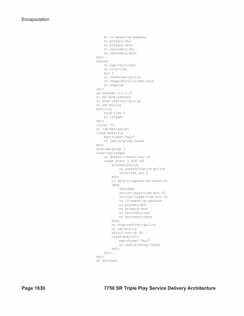
Encapsulation
Page 1830 7750 SR Triple Play Service Delivery Architecture
no l2-aware-ip-address
no primary-dns
no primary-nbns
no secondary-dns
no secondary-nbns
exit
egress
no agg-rate-limit
no hold-time
qos 1
no scheduler-policy
no shape-multi-client-only
no shaping
exit
gw-address 1.1.1.57
no gw-ipv6-address
no http-redirect-policy
no nat-policy
mobility
hold-time 5
no trigger
exit
router 70
no tcp-mss-adjust
track-mobility
mac-format "aa:"
no radius-proxy-cache
exit
wlan-gw-group 3
vlan-tag-ranges
no default-retail-svc-id
range start 0 end 100
authentication
no authentication-policy
hold-time sec 5
exit
no data-triggered-ue-creation
dhcp
shutdown
active-lease-time min 10
initial-lease-time min 10
no l2-aware-ip-address
no primary-dns
no primary-nbns
no secondary-dns
no secondary-nbns
exit
no http-redirect-policy
no nat-policy
retail-svc-id 35
track-mobility
mac-format "aa:"
no radius-proxy-cache
exit
exit
exit
no shutdown
WLAN GW For Mobile Data Offload
7750 SR Triple Play Service Delivery Architecture Page 1831
Data Path
In the upstream direction, the ingress IOM receiving the GRE tunneled packets from the WIFI AP
or AC, load-balances tunnel processing amongst the set of MS-ISAs on the active WLAN-GW
IOMs in the WLAN-GW group. The load-balancing is based on a hash of source IP address in the
outer IP header. The MS-ISA receiving the GRE encapsulated packets removes the tunnel
encapsulation, and internally tunnels (MAC-in-MAC, using BVPLS) the packet to an anchor MS-
ISA on the WLAN-GW IOM. All traffic from a given UE is always forwarded to the same anchor
MS-ISA based on hashing on UE’s MAC address. The MS-ISA provides a mobility anchor point
for the UE. The UE MAC’s association to the GRE tunnel identifier is created or updated. The
corresponding IOM provides ESM functions including ESM lookup, ingress ACLs and QoS.
DHCP packets are forwarded to the CPM from the anchor IOM.
In the downstream direction, the IP packets are forwarded as normal from the network IOM
(based on route lookup yielding subscriber subnet) to the IOM where the ESM host is anchored.
ESM processing including per UE hierarchical policing and LI is performed on the anchor IOM.
Configured MTU on the group-interface is enforced on the IOM, and if required packets are
fragmented. The packets are then forwarded to the appropriate anchor MS-ISA housed by this
IOM. Lookup based on UE’s MAC address is performed to get the tunnel identification, and the
packets are MAC-in-MAC tunneled to the MS-ISA terminating the GRE tunnel. Aggregate
shaping on the tunneled traffic (per tunnel or per retailer) is performed on the carrier IOM housing
the tunnel termination MS-ISA. The tunnel termination MS-ISA removes MAC-in-MAC
encapsulation, and GRE encapsulates the Layer 2 packet, which exits on the Layer 3 SAP to the
carrier IOM. The GRE tunneled packet is forwarded to the right access IOM towards the WIFI AP
based on a routing lookup on IP DA in the outer header.
Tunnel Level Egress QoS
Page 1832 7750 SR Triple Play Service Delivery Architecture
Tunnel Level Egress QoS
Downstream traffic can be subjected to aggregate rate-limit per tunnel or per tunnel and per
retailer combination (in case of wholesale). Typically a unique SSID is used per retailer for
wholesale on the AP, and is reflected via unique dot1Q tag. In the case of a wlan-gw tunnel per AP,
the tunnel encapsulation is performed on the tunnel ISA. The downstream traffic on the tunnel
IOM is received over B-VPLS from the anchor IOM, and is MAC-in-MAC (802.1ah)
encapsulated. I-SID in the packet represents the GRE tunnel or tunnel and retailer combination.
SAP-egress QoS policy defining queues (with rates), and FC to queue mapping, can be specified
under the wlan-gw interface. This policy is applicable to all tunnels (or tunnel and SSID
combinations) associated with the wlan-gw interface, and is attached to corresponding I-SIDs on
the B-VPLS SAP. Traffic is shaped into these queues based on configured queue rates. An
aggregate rate-limit applied across queues on an I-SID (representing tunnel or tunnel and retailer
combination) can be configured under the wlan-gw interface (represented by the wlan-gw node
under the group-interface configuration). The aggregate rate-limit works in conjunction with a
port-scheduler. The port-scheduler corresponds to the internal port between tunnel ISA and its
carrier IOM, and is specified at the wlan-gw IOM group level. The rate-limit includes the B-VPLS
encapsulation overhead. The configuration is shown in Figure 145. Queues per I-SID also work
with virtual-scheduler (with or without a port scheduler). Virtual-scheduling and aggregate-rate
enforcement are mutually exclusive. Configuration is shown in Figure 146. Egress SAP QoS
policy, aggregate rate-limit, port-scheduler, and virtual-schedulers are described in the 7x50 SR
OS QoS Guide. The SAP egress QoS policy associated with a wlan-gw interface implicitly creates
queues (and scheduler association) on ISIDs as corresponding wlan-gw tunnels are created.
General ISID queuing and shaping is defined in the 7x50 SR OS Services Guide.
A configuration node under wlan-gw interface (egress) controls where the egress shaping is
applied, and can specify either tunnel or retailer (tunnel and retailer combination in case of
wholesale). Per I-SID shaping resources can be held after the last subscriber on the tunnel is
deleted, for a configurable amount of time (hold-time) configured under the wlan-gw interface.
During ISA or IOM failover the tunnel resources on the IOM kept due to hold-time are reclaimed.
ISID shaping can be configured (via knob shape-multi-client) to be applied only when there is
more than one UE on the corresponding tunnel (or tunnel and retailer combination). A total of
40,000 shaped tunnels (or shaped tunnel & retailer combinations) are supported per WLAN-GW
IOM. Hardware resources for tunnel (ISID) shapers are shared with subscribers. With 3 WLAN-
GW IOMs per chassis, a maximum of 98,000 (3 *64K / 2) shaped tunnels and subscribers can be
supported per chassis.
WLAN GW For Mobile Data Offload
7750 SR Triple Play Service Delivery Architecture Page 1833
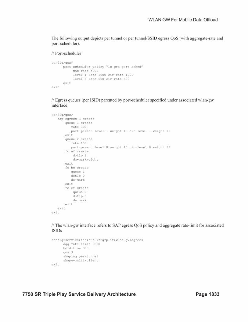
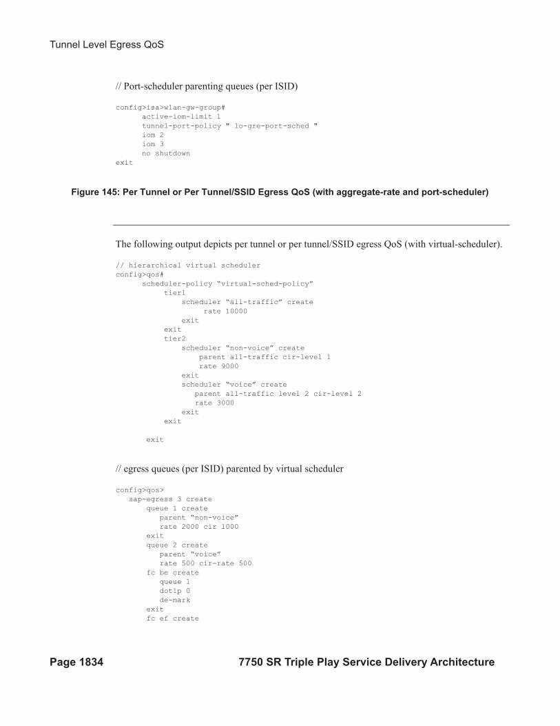
The following output depicts per tunnel or per tunnel/SSID egress QoS (with aggregate-rate and
port-scheduler).
// Port-scheduler
config>qos#
port-scheduler-policy “lo-gre-port-sched”
max-rate 5000
level 1 rate 1000 cir-rate 1000
level 8 rate 500 cir-rate 500
exit
exit
// Egress queues (per ISID) parented by port-scheduler specified under associated wlan-gw
interface
config>qos>
sap-egress 3 create
queue 1 create
rate 300
port-parent level 1 weight 10 cir-level 1 weight 10
exit
queue 2 create
rate 100
port-parent level 8 weight 10 cir-level 8 weight 10
fc af create
dot1p 2
de-markweight
exit
fc be create
queue 1
dot1p 0
de-mark
exit
fc ef create
queue 2
dot1p 5
de-mark
exit
exit
exit
// The wlan-gw interface refers to SAP egress QoS policy and aggregate rate-limit for associated
ISIDs
config>service>ies>sub-if>grp-if>wlan-gw>egress
agg-rate-limit 2000
hold-time 300
qos 3
shaping per-tunnel
shape-multi-client
exit
Tunnel Level Egress QoS
Page 1834 7750 SR Triple Play Service Delivery Architecture
// Port-scheduler parenting queues (per ISID)
config>isa>wlan-gw-group#
active-iom-limit 1
tunnel-port-policy " lo-gre-port-sched "
iom 2
iom 3
no shutdown
exit
Figure 145: Per Tunnel or Per Tunnel/SSID Egress QoS (with aggregate-rate and port-scheduler)
The following output depicts per tunnel or per tunnel/SSID egress QoS (with virtual-scheduler).
// hierarchical virtual scheduler
config>qos#
scheduler-policy “virtual-sched-policy”
tier1
scheduler “all-traffic” create
rate 10000
exit
exit
tier2
scheduler “non-voice” create
parent all-traffic cir-level 1
rate 9000
exit
scheduler “voice” create
parent all-traffic level 2 cir-level 2
rate 3000
exit
exit
exit
// egress queues (per ISID) parented by virtual scheduler
config>qos>
sap-egress 3 create
queue 1 create
parent “non-voice”
rate 2000 cir 1000
exit
queue 2 create
parent “voice”
rate 500 cir-rate 500
fc be create
queue 1
dot1p 0
de-mark
exit
fc ef create
WLAN GW For Mobile Data Offload
7750 SR Triple Play Service Delivery Architecture Page 1835
queue 2
dot1p 5
de-mark
exit
exit
exit
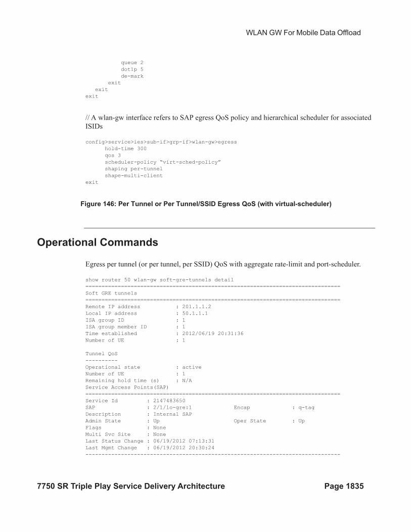
// A wlan-gw interface refers to SAP egress QoS policy and hierarchical scheduler for associated
ISIDs
config>service>ies>sub-if>grp-if>wlan-gw>egress
hold-time 300
qos 3
scheduler-policy “virt-sched-policy”
shaping per-tunnel
shape-multi-client
exit
Figure 146: Per Tunnel or Per Tunnel/SSID Egress QoS (with virtual-scheduler)
Operational Commands
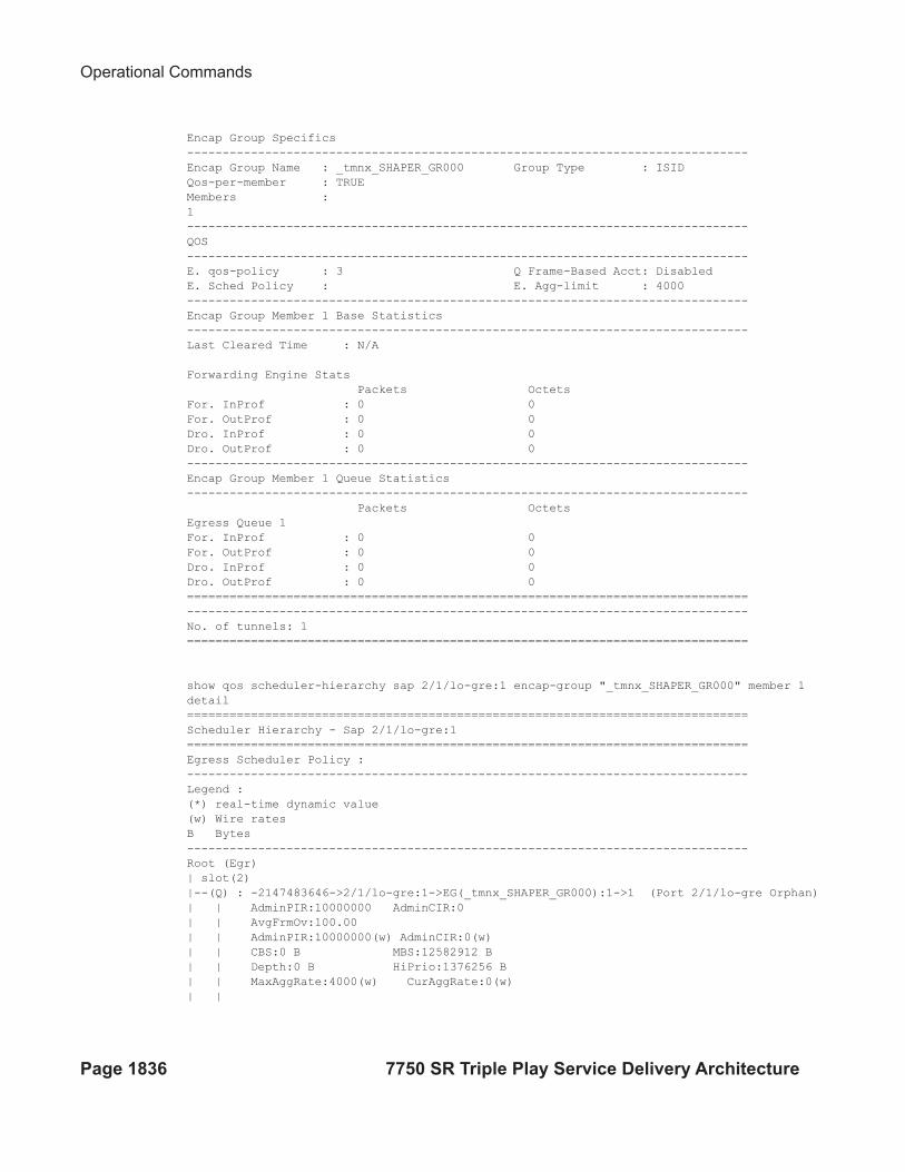
Egress per tunnel (or per tunnel, per SSID) QoS with aggregate rate-limit and port-scheduler.
show router 50 wlan-gw soft-gre-tunnels detail
===============================================================================
Soft GRE tunnels
===============================================================================
Remote IP address : 201.1.1.2
Local IP address : 50.1.1.1
ISA group ID : 1
ISA group member ID : 1
Time established : 2012/06/19 20:31:36
Number of UE : 1
Tunnel QoS
----------
Operational state : active
Number of UE : 1
Remaining hold time (s) : N/A
Service Access Points(SAP)
===============================================================================
Service Id : 2147483650
SAP : 2/1/lo-gre:1 Encap : q-tag
Description : Internal SAP
Admin State : Up Oper State : Up
Flags : None
Multi Svc Site : None
Last Status Change : 06/19/2012 07:13:31
Last Mgmt Change : 06/19/2012 20:30:24
-------------------------------------------------------------------------------
Operational Commands
Page 1836 7750 SR Triple Play Service Delivery Architecture
Encap Group Specifics
-------------------------------------------------------------------------------
Encap Group Name : _tmnx_SHAPER_GR000 Group Type : ISID
Qos-per-member : TRUE
Members :
1
-------------------------------------------------------------------------------
QOS
-------------------------------------------------------------------------------
E. qos-policy : 3 Q Frame-Based Acct: Disabled
E. Sched Policy : E. Agg-limit : 4000
-------------------------------------------------------------------------------
Encap Group Member 1 Base Statistics
-------------------------------------------------------------------------------
Last Cleared Time : N/A
Forwarding Engine Stats
Packets Octets
For. InProf : 0 0
For. OutProf : 0 0
Dro. InProf : 0 0
Dro. OutProf : 0 0
-------------------------------------------------------------------------------
Encap Group Member 1 Queue Statistics
-------------------------------------------------------------------------------
Packets Octets
Egress Queue 1
For. InProf : 0 0
For. OutProf : 0 0
Dro. InProf : 0 0
Dro. OutProf : 0 0
===============================================================================
-------------------------------------------------------------------------------
No. of tunnels: 1
===============================================================================
show qos scheduler-hierarchy sap 2/1/lo-gre:1 encap-group "_tmnx_SHAPER_GR000" member 1
detail
===============================================================================
Scheduler Hierarchy - Sap 2/1/lo-gre:1
===============================================================================
Egress Scheduler Policy :
-------------------------------------------------------------------------------
Legend :
(*) real-time dynamic value
(w) Wire rates
B Bytes
-------------------------------------------------------------------------------
Root (Egr)
| slot(2)
|--(Q) : -2147483646->2/1/lo-gre:1->EG(_tmnx_SHAPER_GR000):1->1 (Port 2/1/lo-gre Orphan)
| | AdminPIR:10000000 AdminCIR:0
| | AvgFrmOv:100.00
| | AdminPIR:10000000(w) AdminCIR:0(w)
| | CBS:0 B MBS:12582912 B
| | Depth:0 B HiPrio:1376256 B
| | MaxAggRate:4000(w) CurAggRate:0(w)
| |
WLAN GW For Mobile Data Offload
7750 SR Triple Play Service Delivery Architecture Page 1837
| | [Within CIR Level 0 Weight 0]
| | Assigned:0(w) Offered:0(w)
| | Consumed:0(w)
| |
| | [Above CIR Level 1 Weight 0]
| | Assigned:4000(w) Offered:0(w)
| | Consumed:0(w)
| |
| | TotalConsumed:0
| | OperPIR:4000 OperCIR:0
| |
| | PktByteOffset:add 0*
| | OnTheWireRates:false
| | ATMOnTheWireRates:false
| | LastMileOnTheWireRates:false
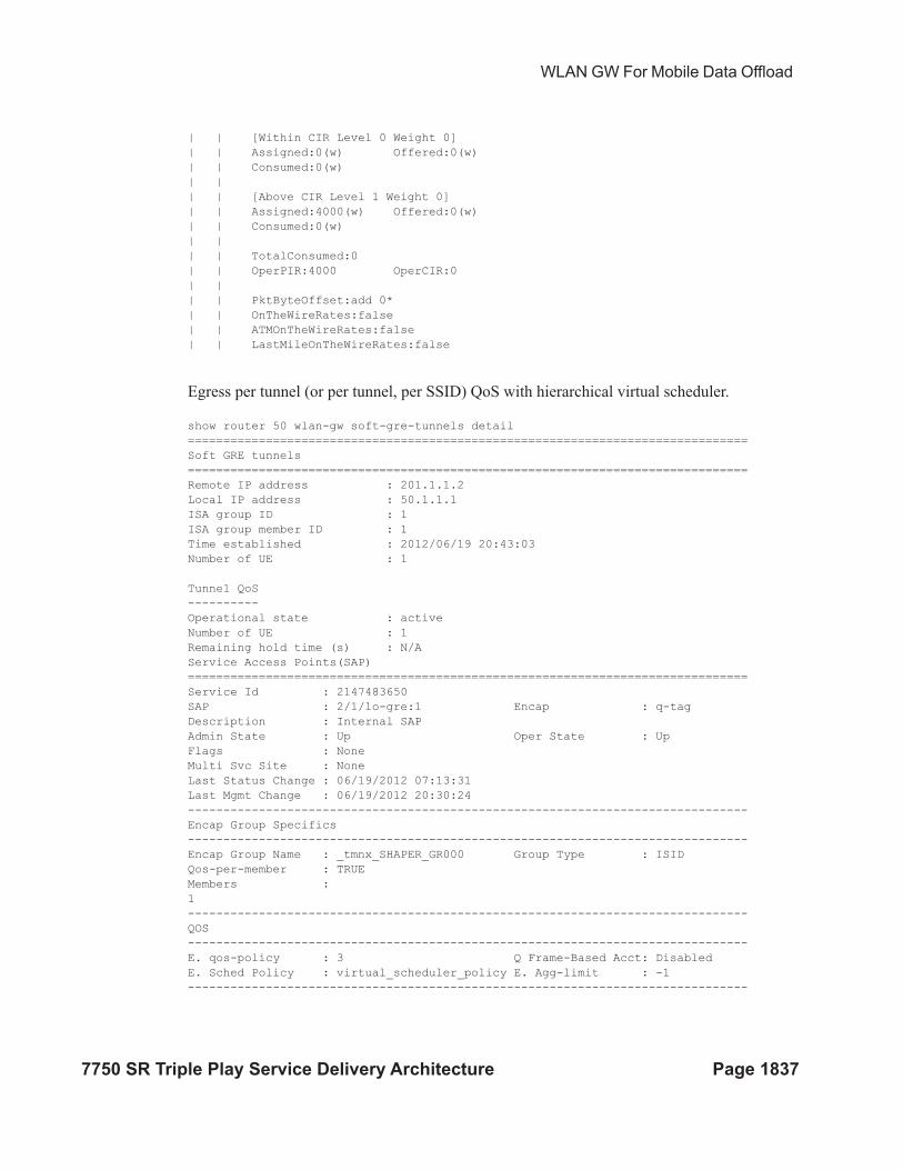
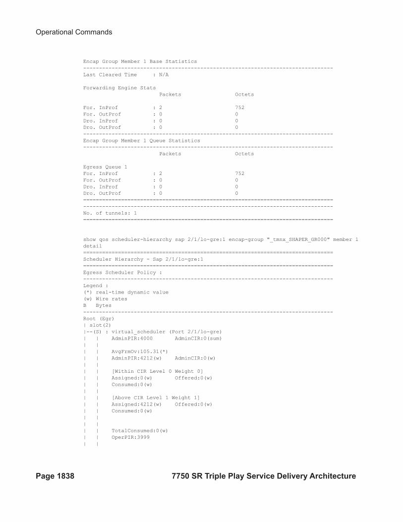
Egress per tunnel (or per tunnel, per SSID) QoS with hierarchical virtual scheduler.
show router 50 wlan-gw soft-gre-tunnels detail
===============================================================================
Soft GRE tunnels
===============================================================================
Remote IP address : 201.1.1.2
Local IP address : 50.1.1.1
ISA group ID : 1
ISA group member ID : 1
Time established : 2012/06/19 20:43:03
Number of UE : 1
Tunnel QoS
----------
Operational state : active
Number of UE : 1
Remaining hold time (s) : N/A
Service Access Points(SAP)
===============================================================================
Service Id : 2147483650
SAP : 2/1/lo-gre:1 Encap : q-tag
Description : Internal SAP
Admin State : Up Oper State : Up
Flags : None
Multi Svc Site : None
Last Status Change : 06/19/2012 07:13:31
Last Mgmt Change : 06/19/2012 20:30:24
-------------------------------------------------------------------------------
Encap Group Specifics
-------------------------------------------------------------------------------
Encap Group Name : _tmnx_SHAPER_GR000 Group Type : ISID
Qos-per-member : TRUE
Members :
1
-------------------------------------------------------------------------------
QOS
-------------------------------------------------------------------------------
E. qos-policy : 3 Q Frame-Based Acct: Disabled
E. Sched Policy : virtual_scheduler_policy E. Agg-limit : -1
-------------------------------------------------------------------------------
Operational Commands
Page 1838 7750 SR Triple Play Service Delivery Architecture
Encap Group Member 1 Base Statistics
-------------------------------------------------------------------------------
Last Cleared Time : N/A
Forwarding Engine Stats
Packets Octets
For. InProf : 2 752
For. OutProf : 0 0
Dro. InProf : 0 0
Dro. OutProf : 0 0
-------------------------------------------------------------------------------
Encap Group Member 1 Queue Statistics
-------------------------------------------------------------------------------
Packets Octets
Egress Queue 1
For. InProf : 2 752
For. OutProf : 0 0
Dro. InProf : 0 0
Dro. OutProf : 0 0
===============================================================================
-------------------------------------------------------------------------------
No. of tunnels: 1
===============================================================================
show qos scheduler-hierarchy sap 2/1/lo-gre:1 encap-group "_tmnx_SHAPER_GR000" member 1
detail
===============================================================================
Scheduler Hierarchy - Sap 2/1/lo-gre:1
===============================================================================
Egress Scheduler Policy :
-------------------------------------------------------------------------------
Legend :
(*) real-time dynamic value
(w) Wire rates
B Bytes
-------------------------------------------------------------------------------
Root (Egr)
| slot(2)
|--(S) : virtual_scheduler (Port 2/1/lo-gre)
| | AdminPIR:4000 AdminCIR:0(sum)
| |
| | AvgFrmOv:105.31(*)
| | AdminPIR:4212(w) AdminCIR:0(w)
| |
| | [Within CIR Level 0 Weight 0]
| | Assigned:0(w) Offered:0(w)
| | Consumed:0(w)
| |
| | [Above CIR Level 1 Weight 1]
| | Assigned:4212(w) Offered:0(w)
| | Consumed:0(w)
| |
| |
| | TotalConsumed:0(w)
| | OperPIR:3999
| |
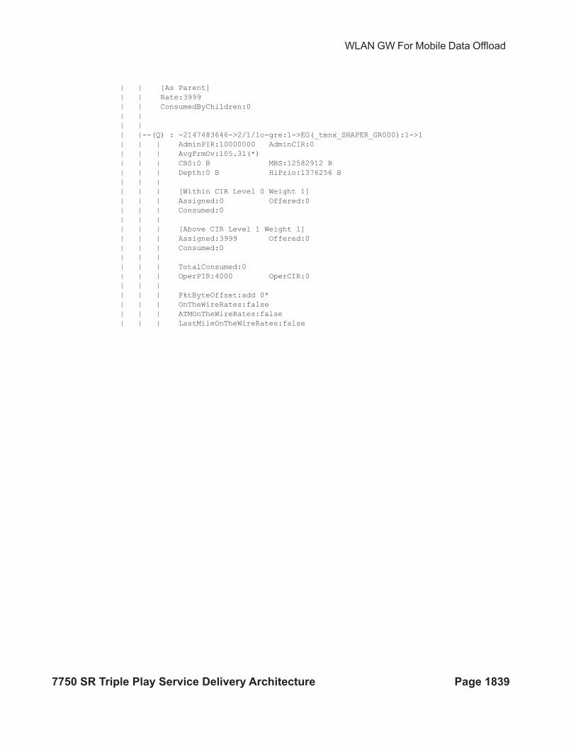
WLAN GW For Mobile Data Offload
7750 SR Triple Play Service Delivery Architecture Page 1839
| | [As Parent]
| | Rate:3999
| | ConsumedByChildren:0
| |
| |
| |--(Q) : -2147483646->2/1/lo-gre:1->EG(_tmnx_SHAPER_GR000):1->1
| | | AdminPIR:10000000 AdminCIR:0
| | | AvgFrmOv:105.31(*)
| | | CBS:0 B MBS:12582912 B
| | | Depth:0 B HiPrio:1376256 B
| | |
| | | [Within CIR Level 0 Weight 1]
| | | Assigned:0 Offered:0
| | | Consumed:0
| | |
| | | [Above CIR Level 1 Weight 1]
| | | Assigned:3999 Offered:0
| | | Consumed:0
| | |
| | | TotalConsumed:0
| | | OperPIR:4000 OperCIR:0
| | |
| | | PktByteOffset:add 0*
| | | OnTheWireRates:false
| | | ATMOnTheWireRates:false
| | | LastMileOnTheWireRates:false
Authentication
Page 1840 7750 SR Triple Play Service Delivery Architecture
Authentication
The solution supports multiple authentication mechanisms. Type of authentication support
depends on the WIFI AP, UE capabilities and customer preference. In case of 802.1x/EAP capable
WIFI APs, supporting secure SSIDs via 802.11i/WPA2, various EAP based authentication such as
SIM/uSIM based (SIM/AKA/AKA’), TTLS, PEAP, certs, etc., are supported. The solution also
supports web-portal based authentication with or without WISPr client on the UE. EAP and portal
authentication works independent of the type of connectivity from the AP (tunneled or native IP).
EAP-Based Authentication
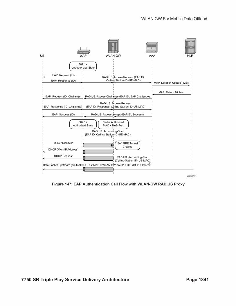
In this model the WIFI AP supports a RADIUS client, and originates RADIUS messages based on
802.1x/EAP exchange with the UE. It sends EAP payload in RADIUS messages towards the
RADIUS server or RADIUS proxy. 7750 WLAN-GW can be configured as a RADIUS proxy for
the WIFI APs. The WIFI AP should be configured with the IP address of the RADIUS proxy, and
should send authentication and accounting messages non-tunneled, natively routed to the
RADIUS proxy. See Figure 147.
The RADIUS proxy function allows 7750 SR to look at the RADIUS authentication and
accounting messages and create or update corresponding subscriber state. RADIUS proxy
transparently forwards RADIUS messages between AP (authenticator) and the AAA server. The
access-request message contains standard RADIUS attributes (including user-name), and the EAP
payload. Standard authentication algorithms negotiated with EAP involve multiple round-trips
(challenge/response) between AP (and UE) and the AAA server.
Once authentication is complete, AAA server passes back subscriber related configuration
parameters as well as the computed session keys (aka pair-wise master key) for 802.11i to the AP.
These keys are encrypted using shared secret between AP (authenticator) and the AAA server.
7750 WLAN-GW can optionally cache authentication information of the subscriber from access-
request and access-accept messages. The cached information allows local authorization of
subsequent DHCP messages from the UEs behind the AP against the cached state on the 7750
RADIUS proxy, and avoids another trip to the RADIUS server.
WLAN GW For Mobile Data Offload
7750 SR Triple Play Service Delivery Architecture Page 1841
Figure 147: EAP Authentication Call Flow with WLAN-GW RADIUS Proxy
WLAN GW AAA
OSSG703
EAP: Request (ID)
EAP: Response (ID)
EAP: Request (ID, Challenge)
EAP: Response (ID, Challenge)
MAP: Location Update (IMSI)
MAP: Return Triplets
RADIUS: Access-Request (EAP ID,
Calling-Station-ID=UE-MAC)
RADIUS: Accounting-Start
(EAP ID, Calling-Station-ID=UE-MAC)
RADIUS: Accounting-Start
(Calling-Station-ID=UE-MAC)
RADIUS: Access-Challenge (EAP ID, EAP Challenge)
EAP: Success (ID) RADIUS: Access-Accept (EAP ID, Success)
RADIUS: Access-Request
(EAP ID, Response, Calling-Station-ID=UE-MAC)
DHCP Discover
DHCP Offer (IP Address)
DHCP Request
802.1X
Unauthorized State
802.1X
Authorized State
Cache Authorized
MAC + NAS-Port
Soft GRE Tunnel
Created
WAPUE HLR
Data Packet Upstream (src MAC=UE, dst MAC = WLAN GW, src IP = UE, dst IP = Internet
EAP-Based Authentication
Page 1842 7750 SR Triple Play Service Delivery Architecture
RADIUS Proxy
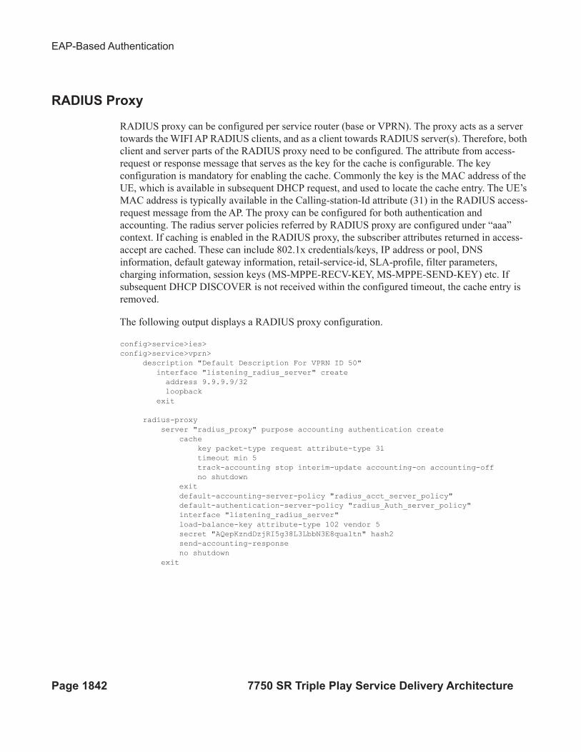
RADIUS proxy can be configured per service router (base or VPRN). The proxy acts as a server
towards the WIFI AP RADIUS clients, and as a client towards RADIUS server(s). Therefore, both
client and server parts of the RADIUS proxy need to be configured. The attribute from access-
request or response message that serves as the key for the cache is configurable. The key
configuration is mandatory for enabling the cache. Commonly the key is the MAC address of the
UE, which is available in subsequent DHCP request, and used to locate the cache entry. The UE’s
MAC address is typically available in the Calling-station-Id attribute (31) in the RADIUS access-
request message from the AP. The proxy can be configured for both authentication and
accounting. The radius server policies referred by RADIUS proxy are configured under “aaa”
context. If caching is enabled in the RADIUS proxy, the subscriber attributes returned in access-
accept are cached. These can include 802.1x credentials/keys, IP address or pool, DNS
information, default gateway information, retail-service-id, SLA-profile, filter parameters,
charging information, session keys (MS-MPPE-RECV-KEY, MS-MPPE-SEND-KEY) etc. If
subsequent DHCP DISCOVER is not received within the configured timeout, the cache entry is
removed.
The following output displays a RADIUS proxy configuration.
config>service>ies>
config>service>vprn>
description "Default Description For VPRN ID 50"
interface "listening_radius_server" create
address 9.9.9.9/32
loopback
exit
radius-proxy
server "radius_proxy" purpose accounting authentication create
cache
key packet-type request attribute-type 31
timeout min 5
track-accounting stop interim-update accounting-on accounting-off
no shutdown
exit
default-accounting-server-policy "radius_acct_server_policy"
default-authentication-server-policy "radius_Auth_server_policy"
interface "listening_radius_server"
load-balance-key attribute-type 102 vendor 5
secret "AQepKzndDzjRI5g38L3LbbN3E8qualtn" hash2
send-accounting-response
no shutdown
exit
WLAN GW For Mobile Data Offload
7750 SR Triple Play Service Delivery Architecture Page 1843
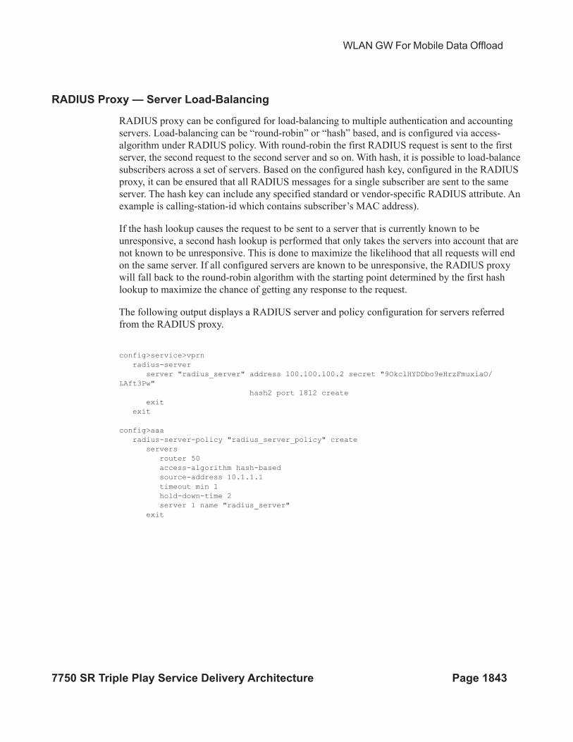
RADIUS Proxy — Server Load-Balancing
RADIUS proxy can be configured for load-balancing to multiple authentication and accounting
servers. Load-balancing can be “round-robin” or “hash” based, and is configured via access-
algorithm under RADIUS policy. With round-robin the first RADIUS request is sent to the first
server, the second request to the second server and so on. With hash, it is possible to load-balance
subscribers across a set of servers. Based on the configured hash key, configured in the RADIUS
proxy, it can be ensured that all RADIUS messages for a single subscriber are sent to the same
server. The hash key can include any specified standard or vendor-specific RADIUS attribute. An
example is calling-station-id which contains subscriber’s MAC address).
If the hash lookup causes the request to be sent to a server that is currently known to be
unresponsive, a second hash lookup is performed that only takes the servers into account that are
not known to be unresponsive. This is done to maximize the likelihood that all requests will end
on the same server. If all configured servers are known to be unresponsive, the RADIUS proxy
will fall back to the round-robin algorithm with the starting point determined by the first hash
lookup to maximize the chance of getting any response to the request.
The following output displays a RADIUS server and policy configuration for servers referred
from the RADIUS proxy.
config>service>vprn
radius-server
server "radius_server" address 100.100.100.2 secret "9OkclHYDDbo9eHrzFmuxiaO/
LAft3Pw"
hash2 port 1812 create
exit
exit
config>aaa
radius-server-policy "radius_server_policy" create
servers
router 50
access-algorithm hash-based
source-address 10.1.1.1
timeout min 1
hold-down-time 2
server 1 name "radius_server"
exit
EAP-Based Authentication
Page 1844 7750 SR Triple Play Service Delivery Architecture
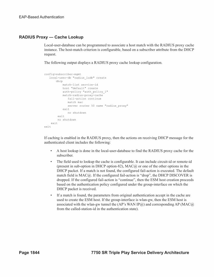
RADIUS Proxy — Cache Lookup
Local-user-database can be programmed to associate a host match with the RADIUS proxy cache
instance. The host-match criterion is configurable, based on a subscriber attribute from the DHCP
request.
The following output displays a RADIUS proxy cache lookup configuration.
config>subscriber-mgmt
local-user-db "radius_ludb" create
dhcp
match-list service-id
host "default" create
auth-policy "auth_policy_1"
match-radius-proxy-cache
fail-action continue
match mac
server router 50 name "radius_proxy"
exit
no shutdown
exit
no shutdown
exit
exit
If caching is enabled in the RADIUS proxy, then the actions on receiving DHCP message for the
authenticated client includes the following:
• A host lookup is done in the local-user-database to find the RADIUS proxy cache for the
subscriber.
• The field used to lookup the cache is configurable. It can include circuit-id or remote-id
(present in sub-option in DHCP option-82), MAC@ or one of the other options in the
DHCP packet. If a match is not found, the configured fail-action is executed. The default
match field is MAC@. If the configured fail-action is “drop”, the DHCP DISCOVER is
dropped. If the configured fail-action is “continue”, then the ESM host creation proceeds
based on the authentication policy configured under the group-interface on which the
DHCP packet is received.
• If a match is found, the parameters from original authentication accept in the cache are
used to create the ESM host. If the group-interface is wlan-gw, then the ESM host is
associated with the wlan-gw tunnel the (AP’s WAN IP@) and corresponding AP (MAC@
from the called-station-id in the authentication state).
WLAN GW For Mobile Data Offload
7750 SR Triple Play Service Delivery Architecture Page 1845
RADIUS Proxy — Accounting
An ESM accounting-start is generated once the ESM host is created on successful authorization of
DHCP against cached authentication state, and IP@ allocation is complete. The accounting-start
contains information from locally cached 802.1x/EAP authentication such as calling-station-id,
called-station-id, NAS-port-id, Subscriber-profile, SLA-profile, NAT port range for subscriber-
aware NAT etc.
If RADIUS proxy is configured as an accounting proxy in addition to authentication proxy, then
the RADIUS proxy transparently forwards the accounting messages to the authentication server(s)
referred from the RADIUS proxy, and can also load-balance. If caching is enabled, then the proxy
can be configured to also track and locally act on the accounting messages, while still
transparently forwarding these messages. The possible actions if accounting messages are tracked
include the following:
• Accounting-start — The WIFI AP RADIUS client generates an accounting-start when a
UE has successfully authenticated and associated with the AP. In cases where after
mobility, the new AP does not re-authenticate due to key caching. accounting-start can be
used as a mobility trigger on the WLAN-GW. Also, in cases where a UE associates with a
single AP but pre-authenticates with multiple APs in range, tracking mobility based on
authentication can falsely associate a UE with incorrect AP. Mobility tracking based on
authentication can be disabled via CLI (no track-authentication under radius-proxy
cache), and instead be performed based on accounting-start. On receiving accounting-
start, the RADIUS proxy on WLAN-GW finds the corresponding ESM host based on the
calling-station-id attribute (typically the MAC@) of the subscriber) in accounting-start
and associates the UE with the RADIUS client (for example, WIFI AP).
• Accounting-stop — The WIFI AP RADIUS client generates an accounting stop if it
detects the UE has disassociated or is deleted due to inactivity or session timeout. The
RADIUS proxy finds the corresponding ESM host based on the calling-station-id
(typically the MAC@) of the subscriber. Note that if the called-station-id is filled out this
must also match with what is currently stored as a security measure. When a UE moves
the called-station-id should get updated and as such an accounting-stop from a previous
AP cannot delete this UE anymore.
• The ESM host is deleted, an ESM accounting-sop message is sent, and the accounting-
stop message from the AP is forwarded to the accounting-server.
• Accounting-ON or Accounting-OFF — This would be received from the AP if the AP has
restarted. The RADIUS proxy will find all the impacted subscribers for the AP based on
the called-station-id attribute (the AP’s MAC@) in the accounting message, and delete all
the corresponding ESM hosts.
• Interim Accounting Updates — If the client moves and re-associates with a new AP, the
RADIUS client in the new AP generates interim-update. The RADIUS-proxy will locate
the impacted ESM host, and update its state to point to the new AP’s MAC@ (as available
in called-station-id in the accounting message). The ESM interim-updates to accounting
EAP-Based Authentication
Page 1846 7750 SR Triple Play Service Delivery Architecture
servers are sent on scheduled interval configured in accounting-policy, but with the
updated information from the interim updates received from the AP.
WLAN GW For Mobile Data Offload
7750 SR Triple Play Service Delivery Architecture Page 1847
Portal Authentication
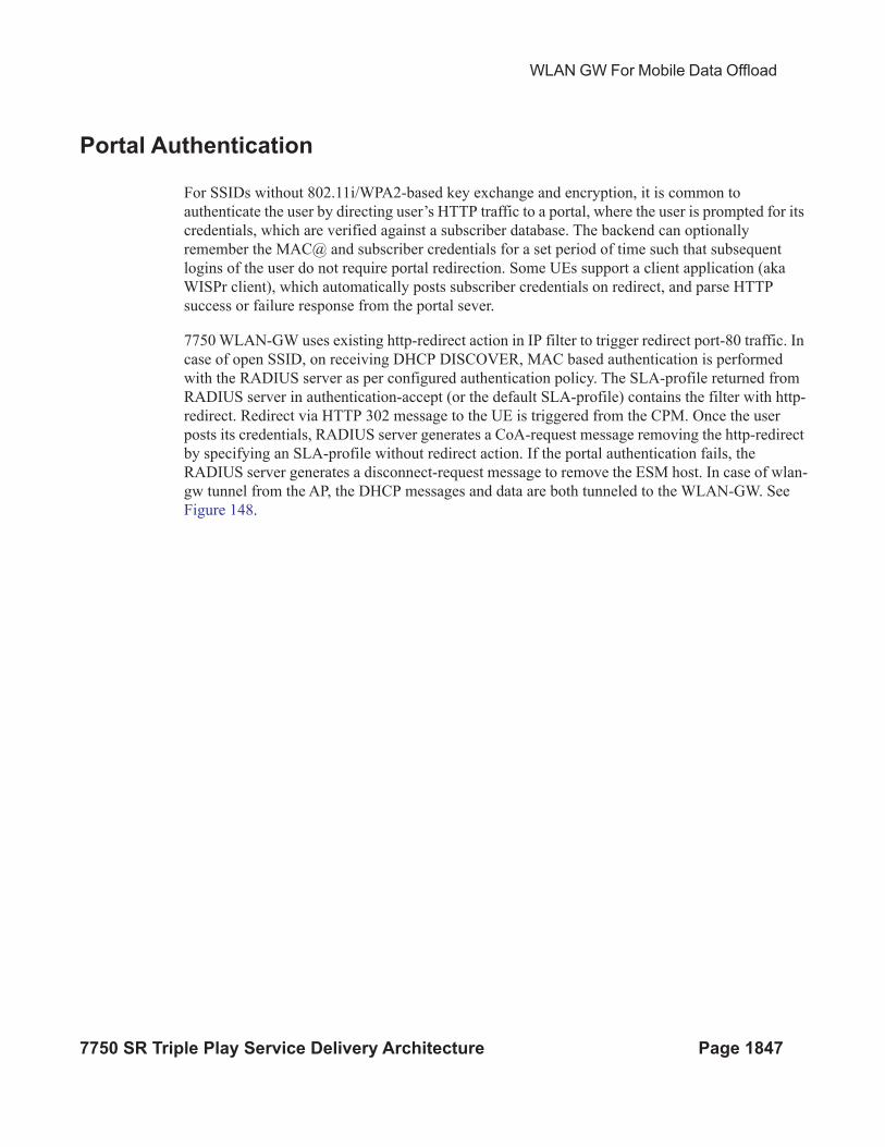
For SSIDs without 802.11i/WPA2-based key exchange and encryption, it is common to
authenticate the user by directing user’s HTTP traffic to a portal, where the user is prompted for its
credentials, which are verified against a subscriber database. The backend can optionally
remember the MAC@ and subscriber credentials for a set period of time such that subsequent
logins of the user do not require portal redirection. Some UEs support a client application (aka
WISPr client), which automatically posts subscriber credentials on redirect, and parse HTTP
success or failure response from the portal sever.
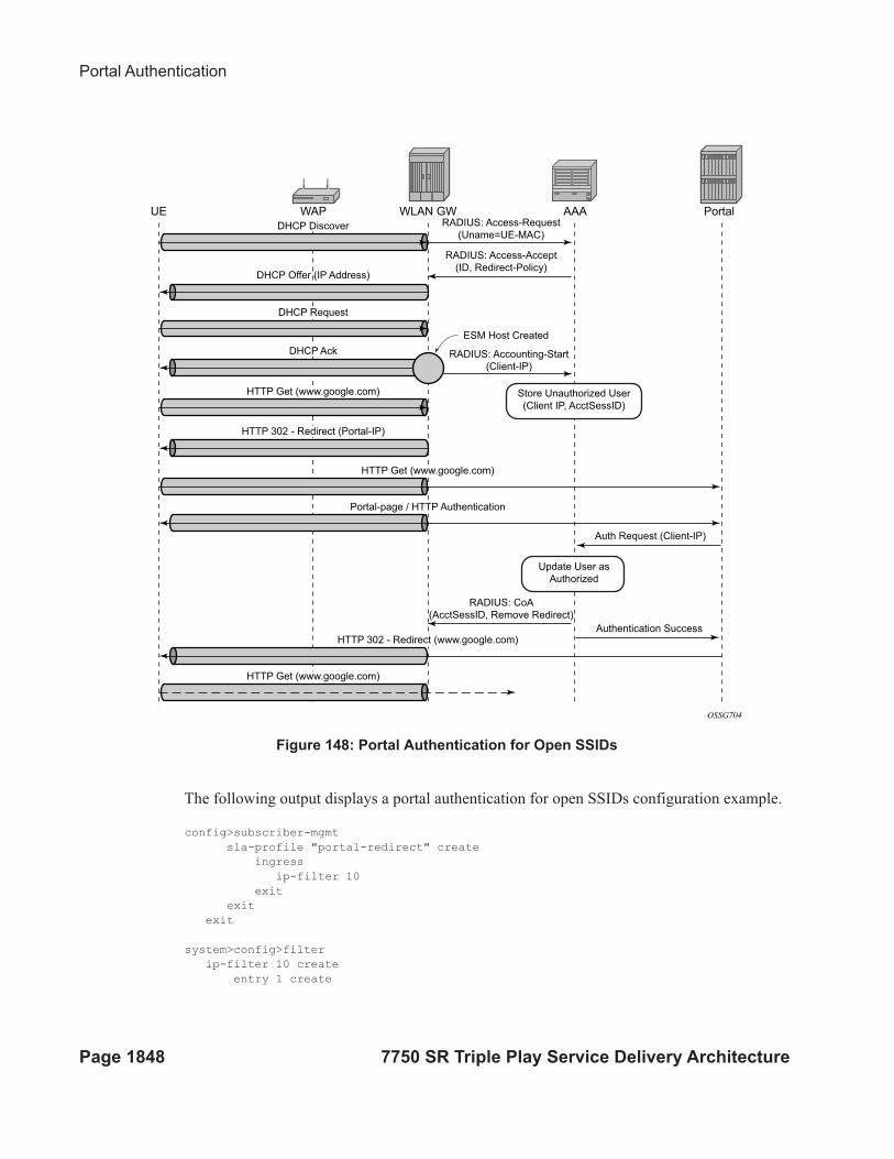
7750 WLAN-GW uses existing http-redirect action in IP filter to trigger redirect port-80 traffic. In
case of open SSID, on receiving DHCP DISCOVER, MAC based authentication is performed
with the RADIUS server as per configured authentication policy. The SLA-profile returned from
RADIUS server in authentication-accept (or the default SLA-profile) contains the filter with http-
redirect. Redirect via HTTP 302 message to the UE is triggered from the CPM. Once the user
posts its credentials, RADIUS server generates a CoA-request message removing the http-redirect
by specifying an SLA-profile without redirect action. If the portal authentication fails, the
RADIUS server generates a disconnect-request message to remove the ESM host. In case of wlan-
gw tunnel from the AP, the DHCP messages and data are both tunneled to the WLAN-GW. See
Figure 148.
Portal Authentication
Page 1848 7750 SR Triple Play Service Delivery Architecture
Figure 148: Portal Authentication for Open SSIDs
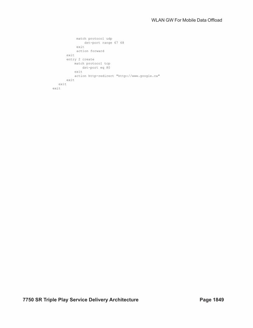
The following output displays a portal authentication for open SSIDs configuration example.
config>subscriber-mgmt
sla-profile "portal-redirect" create
ingress
ip-filter 10
exit
exit
exit
system>config>filter
ip-filter 10 create
entry 1 create
WLAN GW AAA
OSSG704
RADIUS: Access-Request
(Uname=UE-MAC)
RADIUS: Access-Accept
(ID, Redirect-Policy)
RADIUS: Accounting-Start
(Client-IP)
ESM Host Created
Authentication Success
RADIUS: CoA
(AcctSessID, Remove Redirect)
Auth Request (Client-IP)
DHCP Discover
DHCP Offer (IP Address)
DHCP Request
HTTP Get (www.google.com)
HTTP Get (www.google.com)
HTTP Get (www.google.com)
Portal-page / HTTP Authentication
HTTP 302 - Redirect (www.google.com)
HTTP 302 - Redirect (Portal-IP)
Store Unauthorized User
(Client IP, AcctSessID)
Update User as
Authorized
WAPUE Portal
DHCP Ack
WLAN GW For Mobile Data Offload
7750 SR Triple Play Service Delivery Architecture Page 1849
match protocol udp
dst-port range 67 68
exit
action forward
exit
entry 2 create
match protocol tcp
dst-port eq 80
exit
action http-redirect "http://www.google.ca"
exit
exit
exit
Address Assignment
Page 1850 7750 SR Triple Play Service Delivery Architecture
Address Assignment
The address to the UEs can be assigned via local DHCP server from locally defined pools, or from
RADIUS server via local DHCP proxy, or from an external DHCP server. Subscriber-interface
and group-interface are configured as part of normal ESM configuration. In case of wlan-gw, the
group-interface is wlan-gw enabled. Subnets on the subscriber interface are used for the pools
from which the DHCP local server assigns addresses to UEs.
The following output displays an address assignment configuration example.
config>service>vprn
dhcp
local-dhcp-server "dhcp" create #### create local DHCP server
pool “1” create #### define Pool
options
dns-server 8.8.8.8 8.8.4.4
lease-time min 5
exit
subnet 128.203.254.180/30 create
options
subnet-mask 255.255.0.0
default-router 128.203.254.181
exit
address-range 128.203.254.182 128.203.254.183
exit
exit
exit
exit
interface "DHCP-lb" create #### loopback interface with DHCP server
address 10.1.1.1/32
local-dhcp-server "dhcp"
loopback
exit
subscriber-interface "sub-int" create #### subscriber interface
address 128.203.254.181/30 #### Subnets out of which UE
address 10.10.0.1/16 ###### addresses are allocated.
group-interface "group-int" wlgw create
sap-parameters
sub-sla-mgmt
def-sla-profile "sla_def"
def-sub-profile "sub_def"
sub-ident-policy "sub_ident"
exit
exit
exit
dhcp
proxy-server
emulated-server 10.10.0.1 #### proxy to get IP address from AAA
lease-time min 5 #### or from DHCP server. Can provide
no shutdown #### split lease (shorter lease towards client,
exit #### and longer lease towards AAA or DHCP server.
no option
server 10.1.1.1 #### DHCP local server
WLAN GW For Mobile Data Offload
7750 SR Triple Play Service Delivery Architecture Page 1851
trusted
lease-populate 32000
gi-address 128.203.254.181
user-db "radius_ludb" #### LUDB for proxy cache co-relation
no shutdown
exit
exit
WIFI Mobility Anchor
Page 1852 7750 SR Triple Play Service Delivery Architecture
WIFI Mobility Anchor
7750 WLAN-GW supports seamless handling for UE mobility, when a UE moves from one AP to
another, where the new AP is broadcasting the same SSID, and is anchored on the same WLAN-
GW. In case of open SSID, when the UE re-associates with the same SSID on the new AP and
already has an IP@ from association with previous AP, the UE can continue to send and receive
data. The WLAN-GW learns the association of the UE’s MAC address to the GRE tunnel
corresponding to the new AP, and updates its state on the MS-ISA as well as on the CPM. The UE
continues to be anchored on the same anchor MS-ISA, thereby avoiding any disruption in ESM
functions (SLA enforcement and accounting). State update based on data learning results in fast
convergence after mobility and minimal packet loss. The data-triggered mobility can be turned on
via configuration. Mobility trigger can be configured to be restricted to special Ethernet IAPP
frame (originated by the AP with the source MAC of UE).
For 802.1x/EAP based SSIDs, by default the AP requires re-authentication to learn the new
session keys (PMK). 7750-SR as WLAN-GW RADIUS proxy infers mobility from the re-
authentication, and updates the ESM host to point to the new AP. The new AP’s IP address is
derived from the RADIUS attribute NAS-IP-address.The re-authentication also provides the new
session keys to the AP in access-accept RADIUS response. In case the WIFI AP or ACs are
capable of PMK key caching or standard 802.11r (or OKC, the opportunistic key caching pre-
802.11r), the re-authentication on re-association can be avoided. In this case the UE can continue
to send data, and the WLAN-GW can provide fast data-triggered mobility as defined in context of
open SSIDs.
The following output provides a mobility anchor configuration example.
config>service>ies>
config>service>vprn>
subscriber-interface <if-name>
group-interface <if-name> wlangw
wlan-gw
[no] router (base | <vprn-id>) # tunnel service context
[no] wlan-gw-group <group-id>
....snip
mobility
[no] trigger {data | iapp}
[no] hold-time <seconds> // [0..255 secs]
exit
exit
exit
WLAN GW For Mobile Data Offload
7750 SR Triple Play Service Delivery Architecture Page 1853
Wholesale
With EAP the AAA server can look at the realm from the user credential (IMSI) in authentication
request and appropriately provide the service context in retail-service-id, for the ESM host
corresponding to the UE.
For open SSID, the decision can be made by the AAA server based on the SSID. The SSID is
encapsulated in circuit-id sub-option of option-82. The recommended format for the circuit-id is a
string composed of multiple parts (separated by a delimiter) as shown below.
AP-MAC;SSID-STRING;SSID-TYPE
Delimiter is the character ‘;’, and MUST not be allowed in configured SSIDs. AP-MAC sub-string
MUST contain the MAC address of the AP in the format “xx:xx:xx:xx:xx:xx”
SSID-TYPE is “o” for open, and “s” for secure.
For example, if AP-MAC is “00:10:A4:23:19:C0”, SSID is “SP1-wifi”, and SSID-type is secure,
then the value of circuit-id would be the string “00:10:A4:23:19:C0;SP1-wifi;s”.
The circuit-id is passed to the AAA server in initial MAC based authentication on DHCP
DISCOVER. The retail-service-id can be returned in access-accept. This assumes the AP
broadcasts unique SSID per retail provider, and inserts it in Option82 as a DHCP relay-agent. As
an alternative to SSID in option-82, the AP can insert a unique dot1Q tag per retail provider,
before tunneling the Ethernet frame, using single GRE tunnel per AP to the WLAN-GW. 7750
supports configuring a map of .dot1Q tags to retail-service-id. Therefore, the determination of the
retail provider for the subscriber can be made in the data plane when DHCP is received, and the
subscriber state can be created and processed in the right service context.
The following output displays a wholesale configuration example.
config>service>ies>
config>service>vprn>
subscriber-interface <if-name>
group-interface <if-name> wlangw
wlan-gw
[no] router (base | <vprn-id>) # tunnel service context
[no] wlan-gw-group <group-id>
....snip
vlan-tag-ranges # Precedence for retail-service-id:
# RADIUS, vlan-retail-service-map, default-retail-svc [no] vlan start <start-tag> end <end-tag> retail-svc-id <svc-id>
[no] default-retail-svc-id
exit
exit
exit
CGN on WLAN-GW
Page 1854 7750 SR Triple Play Service Delivery Architecture
CGN on WLAN-GW
Both LSN and L2-aware NAT for WIFI subscribers over wlan-gw tunnels is supported. NAT on
WLAN-GW is only supported for locally terminated subscribers and not for GTP tunneled
subscribers. NAT can be performed on the same set of ISAs that are used for WLAN-GW
functions, by referring to the WLAN-GW ISA group from NAT configuration. Alternatively,
dedicated set of ISAs can be used for NAT function by creating and referencing a separate NAT-
group. Configuration related to LSN and L2-aware NAT is provided in SROS MS-ISA guide.
WLAN GW For Mobile Data Offload
7750 SR Triple Play Service Delivery Architecture Page 1855
Lawful Intercept on WLAN-GW
Mirroring traffic for WIFI subscribers to a mediation device, when the subscriber is under legal
intercept is supported. The mirroring function is performed on the anchor IOM where the
subscriber is anchored. Both Ether and IP-only mirror is supported. With Ether mirror, VLAN tags
which are part of internal SAP between ISA and IOM, are included in the mirrored Ethernet frame
of the subscriber. IP-only mirror includes the IP header and the payload. Conventional IP-only
mirror service can be used with direct p2p or MPLS (for remote mirroring) connection to the
mediation device. In addition, routable-encapsulation added in 10R1 is also supported. Both IP/
UDP encapsulation with optional shim-header for subscriber correlation on the mediation device,
and IP/GRE encapsulation is supported with routable-encapsulation of mirrored data. LI can be
triggered via CLI, SNMPv3 or RADIUS, as supported with ESM. RADIUS triggered LI can be
via LI related VSAs in access-accept or in CoA. The CoA is keyed on accounting-session-id. LI is
supported for both local and GTP tunnelled subscribers.
Existing LI support with ESM is described in the SROS OAM and diagnostics guide.
WLAN Location Enhancements
Page 1856 7750 SR Triple Play Service Delivery Architecture
WLAN Location Enhancements
This feature adds configurable support for learning and reporting AP’s MAC address (which
represents WLAN location of the UE), to the AAA server. Support is also added for triggered
interim accounting-updates to report the AP’s MAC@ to the AAA server.
Triggered Interim Accounting-Updates
Using location based policy for WIFI subscribers is important. The business logic in AAA could
use the location of the subscriber. Therefore, it is important to notify location change of the
subscriber to AAA. Standard way to do this is by generating an interim accounting update when
the WLAN-GW learns of the location change for a subscriber. The location for a WIFI subscriber
can be inferred from MAC@ (preferred) or WAN IP@ of the AP.
For open-SSID, learning about mobility could be “data-triggered” or “IAPP packet triggered.” If
triggered, interim accounting-update is configured via CLI, then on detecting a location change for
the UE, an interim accounting-update is sent immediately to the AAA server with the new AP’s
MAC@ (if already known to WLAN-GW). The accounting-update contains NASP-port-id (which
contains the AP’s IP@), and circuit-id (from DHCP option-82) which contains AP’s MAC@ and
SSID. In case of data-triggered mobility, if the new AP’s MAC@ is not already known to WLAN-
GW, a GRE encapsulated ARP packet is generated towards the AP to learn the MAC@ of the AP.
The AP is expected to reply with a GRE encapsulated ARP response containing its MAC@. The
generation of ARP to learn the AP’s MAC@ is controlled via CLI. The GRE encapsulated ARP
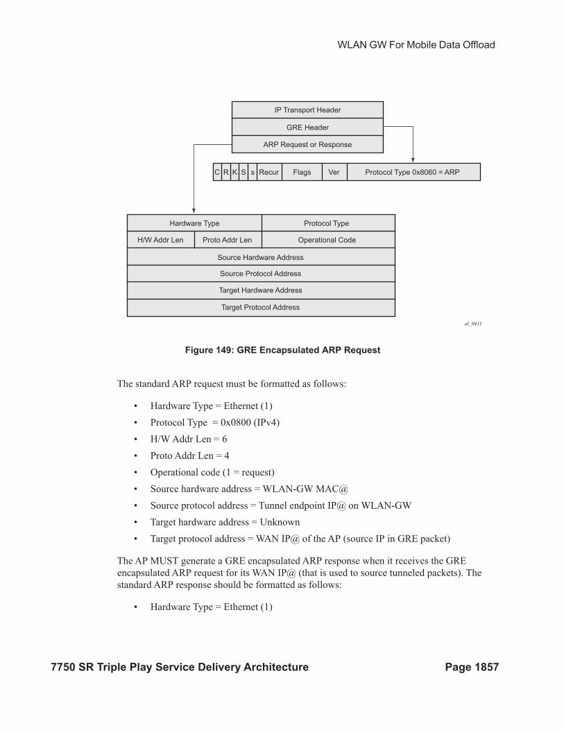
packet is shown in Figure 149.
WLAN GW For Mobile Data Offload
7750 SR Triple Play Service Delivery Architecture Page 1857
Figure 149: GRE Encapsulated ARP Request
The standard ARP request must be formatted as follows:
• Hardware Type = Ethernet (1)
• Protocol Type = 0x0800 (IPv4)
• H/W Addr Len = 6
• Proto Addr Len = 4
• Operational code (1 = request)
• Source hardware address = WLAN-GW MAC@
• Source protocol address = Tunnel endpoint IP@ on WLAN-GW
• Target hardware address = Unknown
• Target protocol address = WAN IP@ of the AP (source IP in GRE packet)
The AP MUST generate a GRE encapsulated ARP response when it receives the GRE
encapsulated ARP request for its WAN IP@ (that is used to source tunneled packets). The
standard ARP response should be formatted as follows:
• Hardware Type = Ethernet (1)
al_0411
IP Transport Header
GRE Header
ARP Request or Response
Protocol Type 0x8060 = ARPVerFlags
Hardware Type
H/W Addr Len Proto Addr Len Operational Code
Source Hardware Address
Source Protocol Address
Target Hardware Address
Target Protocol Address
Protocol Type
RecursSKRC
Operational Support
Page 1858 7750 SR Triple Play Service Delivery Architecture
• Protocol Type = 0x0800 (IPv4)
• H/W Addr Len = 6
• Proto Addr Len = 4
• Operational code (2 = response)
• Source hardware address = AP MAC@
• Source protocol address = WAN IP@ of AP (used for sourcing tunneled packets)
• Target hardware address = source hardware address from the request
• Target protocol address = source protocol address from ARP request
For 802.1x/EAP SSID, the location change (mobility) is learnt from an interim-accounting update
from the AP. The called-station-Id (containing the AP MAC@) is compared against the current
stored called-station-Id that the subscriber is associated with. If the called-station-id is different
then the received interim accounting update is immediately forwarded to the accounting server, if
triggered interim accounting-update is configured via CLI. In previous releases, the interim-
update received from the AP is not immediately forwarded by the accounting proxy. Only a
regularly scheduled interim-update is sent.
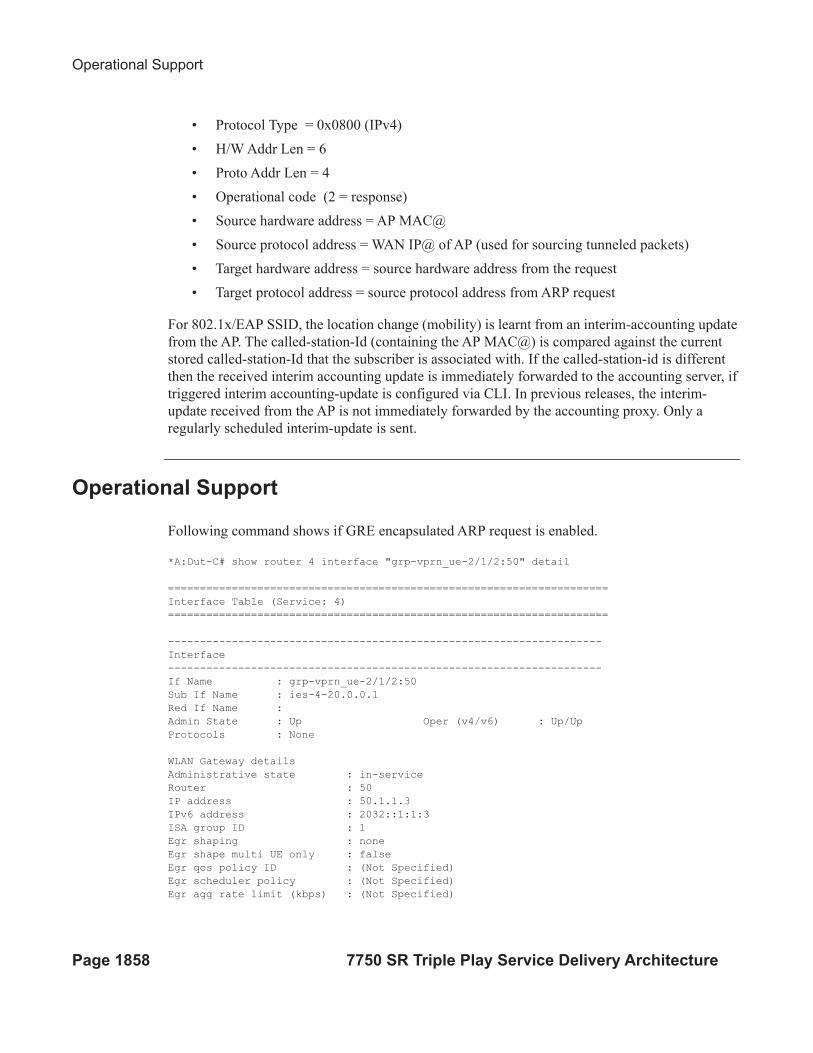
Operational Support
Following command shows if GRE encapsulated ARP request is enabled.
*A:Dut-C# show router 4 interface "grp-vprn_ue-2/1/2:50" detail
=====================================================================
Interface Table (Service: 4)
=====================================================================
--------------------------------------------------------------------
Interface
--------------------------------------------------------------------
If Name : grp-vprn_ue-2/1/2:50
Sub If Name : ies-4-20.0.0.1
Red If Name :
Admin State : Up Oper (v4/v6) : Up/Up
Protocols : None
WLAN Gateway details
Administrative state : in-service
Router : 50
IP address : 50.1.1.3
IPv6 address : 2032::1:1:3
ISA group ID : 1
Egr shaping : none
Egr shape multi UE only : false
Egr qos policy ID : (Not Specified)
Egr scheduler policy : (Not Specified)
Egr agg rate limit (kbps) : (Not Specified)
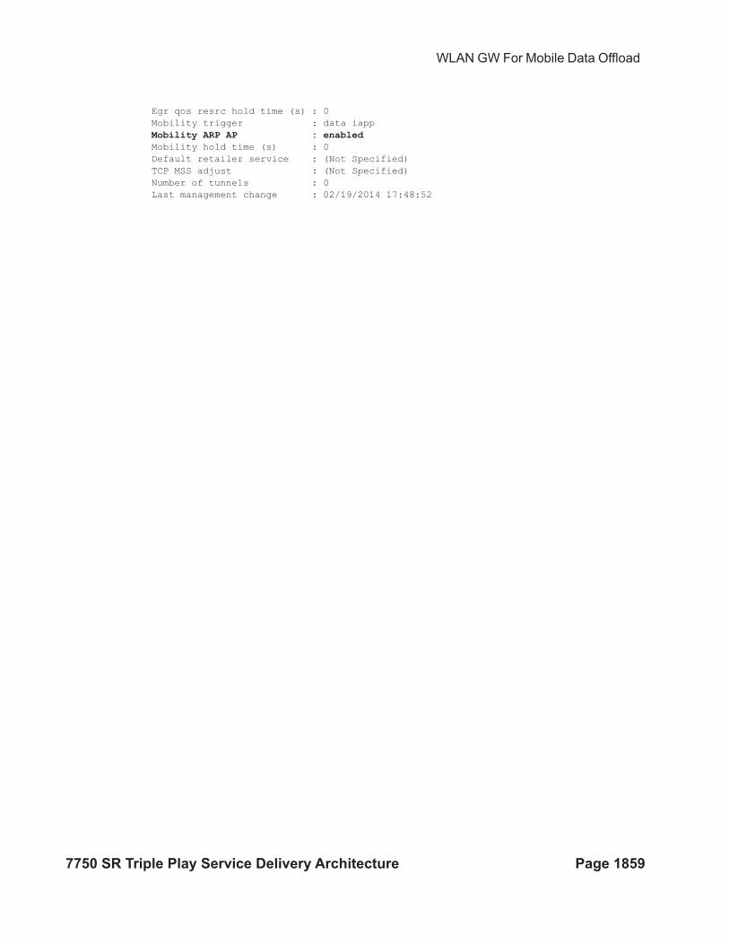
WLAN GW For Mobile Data Offload
7750 SR Triple Play Service Delivery Architecture Page 1859
Egr qos resrc hold time (s) : 0
Mobility trigger : data iapp
Mobility ARP AP : enabled
Mobility hold time (s) : 0
Default retailer service : (Not Specified)
TCP MSS adjust : (Not Specified)
Number of tunnels : 0
Last management change : 02/19/2014 17:48:52
WIFI Offload – 3G/4G Interworking
Page 1860 7750 SR Triple Play Service Delivery Architecture
WIFI Offload – 3G/4G Interworking
This feature adds support for WIFI to 3G/4G interworking on WLAN-GW based on setting up
per-UE GTP tunnel from WLAN-GW to the mobile packet core. The feature involves setting up
per-UE GTP tunnel from the WLAN-GW to the GGSN or PGW based on authenticating the UE.
Access to only a single APN (default WLAN APN) per UE is supported. This default WLAN
APN for the UE is obtained in authentication response from the AAA server. A single primary
PDP context per UE is supported on the Gn interface (3GPP TS 29.060 Release 8) from WLAN-
GW to the GGSN. Single default-bearer per UE is supported on S2b interface (3GPP TS 29.274
Release 10), and S2a interface (work-in-progress for SAMOG Release 11) from WLAN-GW to
the PGW. The GTP tunnel setup is triggered via DHCP from the UE after it is successfully
authenticated. The IP@ for the UE is obtained via GTP from the GGSN or PGW and returned to
the UE in DHCP. The bridged WIFI AP connectivity with the WLAN-GW can be wlan-gw based
(L2oGRE or L2VPNoGRE) or can be a native L2 (VLAN). A maximum of 128,000 PDP-contexts
or bearers are supported per WLAN-GW. GTP-U encapsulation requires IOM3.
Signaling Call Flow
The decision to setup a GTP tunnel for a subscriber or locally breakout subscriber’s traffic is AAA
based, and received in authentication response. If the traffic is to be tunneled to the PGW or
GGSN, the signaling interface or PGW/GGSN interface would be provided via AAA. Absence of
these attributes in the authentication response implicitly signifies local-breakout.
GTP Setup with EAP Authentication
Once the EAP authentication completes as described in the section on authentication, the
RADIUS proxy caches the authentication response, including any attributes related to GTP
signaling. Subsequently DHCP is initiated from the UE. On receiving DHCP DISCOVER, the
RADIUS proxy cache is matched to get the AAA parameters related to the UE from the original
authentication response. If PGW/GGSN (mobile gateway) IP address is not present in cached
authentication, DNS resolution as described in section 1.2 is initiated for the WLAN APN
obtained from AAA (in the cache) or for locally configured APN in the service associated with the
UE. The DNS resolution provides a set of IP addresses for the mobile gateways. The GTP tunnel
setup is attempted to the selected mobile gateway. The IP address provided by PGW/GGSN in the
GTP response is returned in DHCP offer to the UE. The WLAN-GW acts as a DHCP to GTP
proxy. The WLAN-GW is the default-GW for the UE. Any packets from the UE are then GTP
tunneled to the mobile gateway. If the UE requests an IP address (for which it may have an
existing lease on one of its interface) via DHCP option 50 in the DHCP request, then WLAN-GW
sets the “handover bit” in the GTP session create message, and indicates the requested address in
the PDN Address Allocation (PAA) field. This allows the PGW to look for existing session
corresponding to the signaled IMSI and APN (with potentially different RAT-Type) and return its
WLAN GW For Mobile Data Offload
7750 SR Triple Play Service Delivery Architecture Page 1861
existing IP address in session create response. The old session and bearer is deleted by the PGW.
The signaling of “handover bit” is supported with S2a and S2b (release 10 and beyond). The IP
address cannot be preserved over the Gn interface. The call flow in Figure 156 shows basic GTP
setup (with S2a), the output provided on page 1878 show IP address preservation across inter-
access (WIFI <-> 4G) moves.
DHCP release or lease timeout on WLAN-GW will result in deletion of the GTP tunnel
corresponding to the UE. The session or PDP context deactivation from PGW/GGSN will also
result in removal of the GTP state for the UE and the corresponding ESM host on WLAN-GW. In
this SR-OS release, only default bearer (or primary PDP context) for single default APN is
handled over WIFI. GTP path-management messages (echo request and reply) are supported.
Mandatory IEs are supported in GTP signaling. Hard coded default values are signaled for QoS
and charging related IEs. For GTPv2, the bearer is signaled as non-GBR bearer with QCI value of
8, and MBR/GBR values of 0. APN-AMBR default values signaled are 20Mbps/10Mbps
downstream/upstream. For GTPv1, reliability and priority classes default to “best-effort”,
allocation/retention priority defaults to 1, and the default peak-rate corresponds to class 9 (bit-wise
1001) which is slightly over 2Mbps. Charging characteristics IE which contains a 16 bit flag
defaults to 0. In the future, RADIUS returned values or locally configurable values will be
signaled in QoS and charging IEs.
The IP address is returned in the create PDP context response or Create session response. The
DNS server addresses for the UE are retuned in IP control protocol (IPCP) option in a PCO IE in
the response. The default gateway address provided to the UE in DHCP is auto-generated
algorithmically on the WLAN-GW from the IP address returned by the PGW/GGSN for the UE.
The WIFI AP is required to provide a split-horizon function, where there is no local switching on
the AP, and all communication to/from any AP is via WLAN-GW. The WLAN-GW implements
proxy-ARP and forwards all received traffic from the UE into the GTP tunnel. In the future, the
default-GW address to be returned to the UE could be obtained in a PCO from the PGW/GGSN.
The GTP-U processing of data packets is done in the IOM.
APN Resolution
The default WLAN APN is either configured via CLI or obtained from RADIUS in authentication
response. The APN FQDN is constructed and resolved in DNS to obtain a set of GGSN/PGW IP
addresses. The GTP sessions for UEs are load-balanced across the set of these gateways in a
round-robin fashion. The APN FQDN generated for DNS resolution is composed of the Network-
ID (NI) portion and the Operator-ID (OI) portion (MCC and MNC) as per 3GPP TS 29.303 and is
formatted as APN-NI.apn.epc.mnc<MNC>.mcc<MCC>.3gppnetwork.org. Only basic DNS
procedure and A-records from DNS server are supported in this release. S-NAPTR procedure is
not yet supported and will be added in a follow-on release. The NI portion or both NI and OI
portions of the APN can be locally configured or supplied via RADIUS in a VSA (Alc-Wlan-
APN-Name). By default the Operator-ID (OI) portion of the APN is learnt from the IMSI. If the
RADIUS returns both the NI and OI portions in the APN attribute, then it is used as is for the
FQDN construction. A DNS resolution is limited to a maximum of 20 IP addresses in this
Configuration Objects
Page 1862 7750 SR Triple Play Service Delivery Architecture
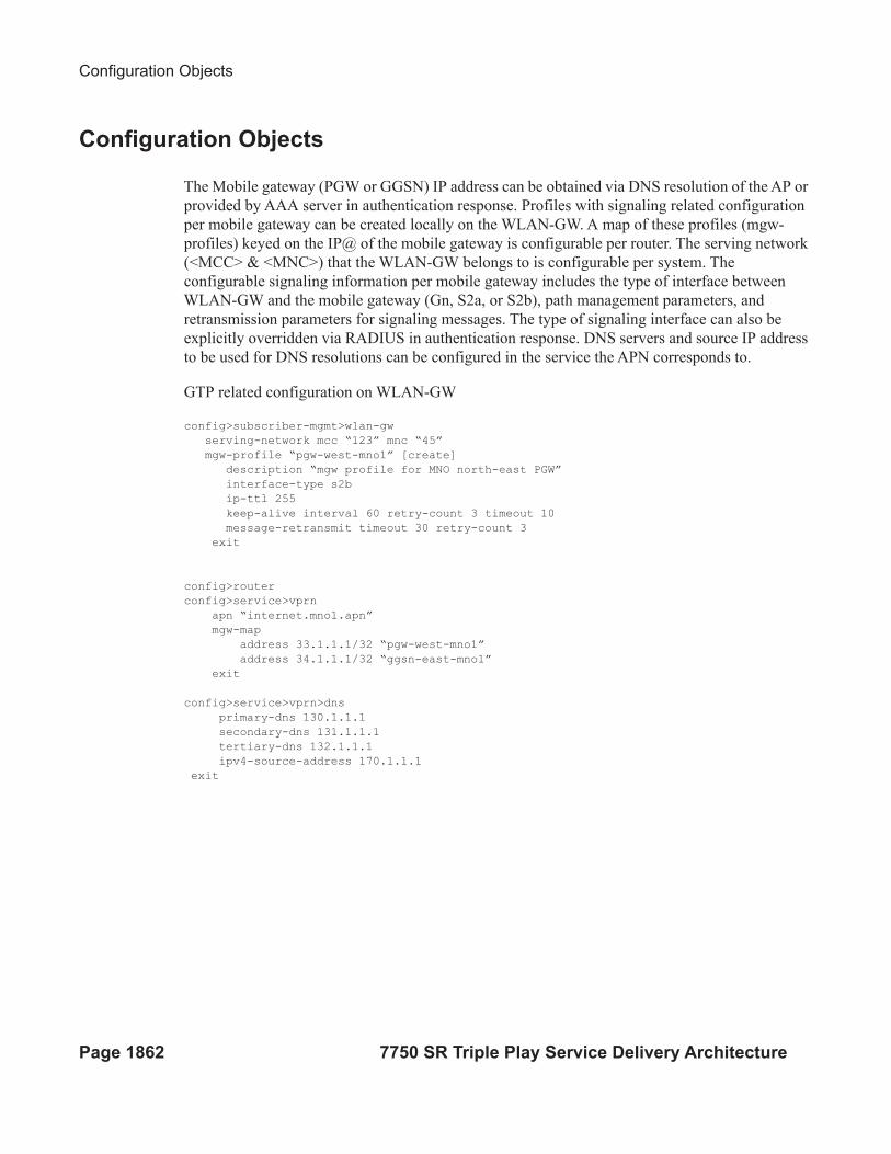
Configuration Objects
The Mobile gateway (PGW or GGSN) IP address can be obtained via DNS resolution of the AP or
provided by AAA server in authentication response. Profiles with signaling related configuration
per mobile gateway can be created locally on the WLAN-GW. A map of these profiles (mgw-
profiles) keyed on the IP@ of the mobile gateway is configurable per router. The serving network
(<MCC> & <MNC>) that the WLAN-GW belongs to is configurable per system. The
configurable signaling information per mobile gateway includes the type of interface between
WLAN-GW and the mobile gateway (Gn, S2a, or S2b), path management parameters, and
retransmission parameters for signaling messages. The type of signaling interface can also be
explicitly overridden via RADIUS in authentication response. DNS servers and source IP address
to be used for DNS resolutions can be configured in the service the APN corresponds to.
GTP related configuration on WLAN-GW
config>subscriber-mgmt>wlan-gw
serving-network mcc “123” mnc “45”
mgw-profile “pgw-west-mno1” [create]
description “mgw profile for MNO north-east PGW”
interface-type s2b
ip-ttl 255
keep-alive interval 60 retry-count 3 timeout 10
message-retransmit timeout 30 retry-count 3
exit
config>router
config>service>vprn
apn “internet.mno1.apn”
mgw-map
address 33.1.1.1/32 “pgw-west-mno1”
address 34.1.1.1/32 “ggsn-east-mno1”
exit
config>service>vprn>dns
primary-dns 130.1.1.1
secondary-dns 131.1.1.1
tertiary-dns 132.1.1.1
ipv4-source-address 170.1.1.1
exit
WLAN GW For Mobile Data Offload
7750 SR Triple Play Service Delivery Architecture Page 1863
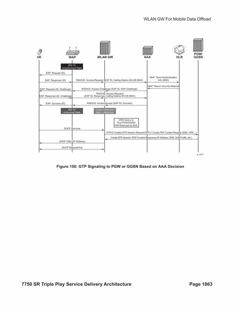
Figure 150: GTP Signaling to PGW or GGSN Based on AAA Decision
al_0071
EAP: Request (ID)
RADIUS: Access-Request (EAP ID, Calling-Station-ID=UE-MAC)
MAP: Send AuthenticationInfo (IMSI)
MAP: Return Security MaterialRADIUS: Access-Challenge (EAP ID, EAP Challenge)
RADIUS: Access-Request(EAP ID, Response, Calling-Station-ID=UE-MAC)
RADIUS: Access-Accept (EAP ID, Success)
EAP: Response (ID)
EAP: Request (ID, Challenge)
EAP: Response (ID, Challenge)
EAP: Success (ID)
DHCP Offer (IP Address)
DHCP Request/Ack
DHCP Discover
GTPv2 Creates EPS Session Request/GTPv1 Create PDP Context Request (IMSI, APN,...)
Create EPS Session /PDP Context Response (IP Address, DNS, QoS Profile, etc.)
UE WAP WLAN GW
PGW/
GGSNAAA HLR
802.1XUnauthorized State
802.1XAuthorized State
Cache AuthorizedMAC + NAS-Port
DNS Query toFind PGW/GGSN
OR Returned by AAA
Configuration Objects
Page 1864 7750 SR Triple Play Service Delivery Architecture
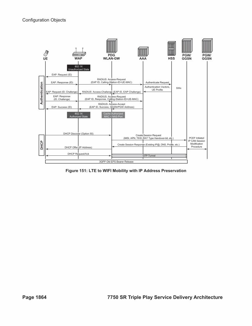
Figure 151: LTE to WIFI Mobility with IP Address Preservation
al_0072
Authenticate Request
Authentication Vectors,UE Profile
SWx
RADIUS: Access-Request(EAP ID, Calling-Station-ID=UE-MAC)
RADIUS: Access-Challenge (EAP ID, EAP Challenge)
RADIUS: Access-Request(EAP ID, Response, Calling-Station-ID=UE-MAC)
RADIUS: Access-Accept(EAP ID, Success, GGSN/PGW Address)
EAP: Request (ID)
EAP: Response (ID)
EAP: Request (ID, Challenge)
EAP: Response(ID, Challenge)
EAP: Success (ID)
DHCP Offer (IP Address)
DHCP Request/Ack
3GPP Old EPS Bearer Release
DHCP Discover (Option 50)Create Session Request
(IMSI, APN, TEID, RAT Type Handover-bit, etc.)
Create Session Response (Existing IP@, DNS, Profile, etc.)
GTP Tunnel
PCEF InitiatedIP CAN Session
ModificationProcedure
UE
Authentication
DHCP
WAP
PGW/
GGSN
PGW/
GGSN
PDG
WLAN-GW AAA HSS
802.1XUnauthorized State
802.1XAuthorized State
Cache AuthorizedMAC + NAS-Port
WLAN GW For Mobile Data Offload
7750 SR Triple Play Service Delivery Architecture Page 1865
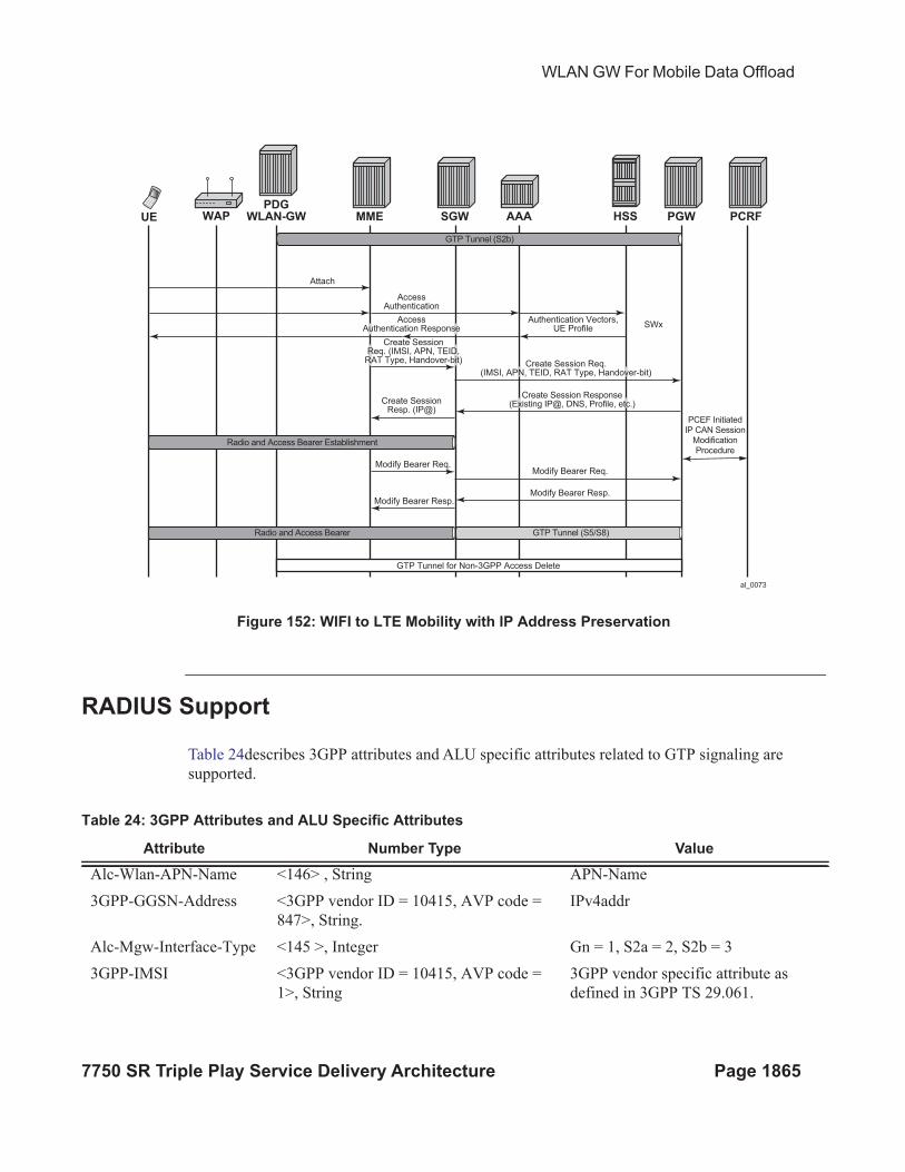
Figure 152: WIFI to LTE Mobility with IP Address Preservation
RADIUS Support
Table 24describes 3GPP attributes and ALU specific attributes related to GTP signaling are
supported.
al_0073
Attach
Modify Bearer Req.
PCEF InitiatedIP CAN Session
ModificationProcedure
Modify Bearer Req.
Modify Bearer Resp.Modify Bearer Resp.
SWx
AccessAuthentication
Create SessionResp. (IP@)
Create SessionReq. (IMSI, APN, TEID,
RAT Type, Handover-bit) Create Session Req.(IMSI, APN, TEID, RAT Type, Handover-bit)
Create Session Response(Existing IP@, DNS, Profile, etc.)
AccessAuthentication Response
Authentication Vectors,UE Profile
GTP Tunnel for Non-3GPP Access Delete
GTP Tunnel (S2b)
Radio and Access Bearer Establishment
Radio and Access Bearer GTP Tunnel (S5/S8)
UE WAP
PDG
WLAN-GW MME SGW PGW PCRFAAA HSS
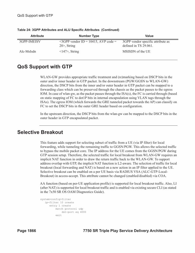
Table 24: 3GPP Attributes and ALU Specific Attributes
Attribute Number Type Value
Alc-Wlan-APN-Name <146> , String APN-Name
3GPP-GGSN-Address <3GPP vendor ID = 10415, AVP code =
847>, String.
IPv4addr
Alc-Mgw-Interface-Type <145 >, Integer Gn = 1, S2a = 2, S2b = 3
3GPP-IMSI <3GPP vendor ID = 10415, AVP code =
1>, String
3GPP vendor specific attribute as
defined in 3GPP TS 29.061.
QoS Support with GTP
Page 1866 7750 SR Triple Play Service Delivery Architecture
QoS Support with GTP
WLAN-GW provides appropriate traffic treatment and (re)marking based on DSCP bits in the
outer and/or inner header in GTP packet. In the downstream (PGW/GGSN to WLAN-GW)
direction, the DSCP bits from the inner and/or outer header in GTP packet can be mapped to a
forwarding class which can be preserved through the chassis as the packet passes to the egress
IOM. In case of wlan-gw, as the packet passes through the ISA(s), the FC is carried through (based
on static mapping of FC to dot1P bits in internal encapsulation using VLAN tags through the
ISAs). The egress IOM (which forwards the GRE tunneled packet towards the AP) can classify on
FC to set the DSCP bits in the outer GRE header based on configuration.
In the upstream direction, the DSCP bits from the wlan-gw can be mapped to the DSCP bits in the
outer header in GTP encapsulated packet.
Selective Breakout
This feature adds support for selecting subset of traffic from a UE (via IP filter) for local
forwarding, while tunneling the remaining traffic to GGSN/PGW. This allows the selected traffic
to bypass the mobile packet core. The IP address for the UE comes from the GGSN/PGW during
GTP session setup. Therefore, the selected traffic for local breakout from WLAN-GW requires an
implicit NAT function in order to draw the return traffic back to the WLAN-GW. To support
address overlap with GTP, the implicit NAT function is L2-aware. The selection of traffic for local
breakout (local forwarding and NAT) is based on a new action in an IP filter applied to the UE.
Selective breakout can be enabled on a per UE basis via RADIUS VSA (ALC-GTP-Local-
Breakout) in access-accept. This attribute cannot be changed (enabled/disabled) via COA.
AA function (based on per-UE application profile) is supported for local breakout traffic. Also, LI
(after NAT) is supported for local breakout traffic and is enabled via existing secure CLI (as stated
in the 7x50 SR OS OAM Diagnostics Guide).
system>config>filter
ip-filter 10 create
entry 1 create
match protocol udp
dst-port eq 4000
exit
3GPP-IMEISV <3GPP vendor ID = 10415, AVP code =
20>, String
3GPP vendor specific attribute as
defined in TS 29.061.
Alc-MsIsdn <147>, String MSISDN of the UE
Table 24: 3GPP Attributes and ALU Specific Attributes (Continued)
Attribute Number Type Value
WLAN GW For Mobile Data Offload
7750 SR Triple Play Service Delivery Architecture Page 1867
action gtp-local-breakout
exit
On traffic ingressing WLAN-GW from the UE, normal ESM host lookup and CAM lookup with
ingress host filter is performed. If there is a match in the filter indicating “gtp-local-breakout,” the
traffic is forwarded within the chassis to the WLAN-GW anchor IOM for the UE, where it is
subjected to L2-aware NAT function and is IP forwarded to the destination based on FIB lookup.
The inside IP address is the address returned in GTP, and the outside IP is an address belonging to
NAT outside IP address range on the ISA. If there is no match in the filer, the traffic is GTP
tunneled using the TEIDs corresponding to the ESM host. The traffic received from the network
can be a normal L3 packet or a GTP encapsulated packet. The normal L3 packet is expected to be
destined to the NAT outside IP and is normally routed to the NAT ISA.
By default, per UE accounting includes counters that are aggregated across GTP and local-
breakout traffic. Separate counters can be obtained by directing the GTP and local-breakout traffic
into different queues associated with the corresponding ESM host. NAT information (outside IP
and port range) associated with an ESM host subjected to selective breakout is included in
accounting-updates.
Location Notification in S2a
Page 1868 7750 SR Triple Play Service Delivery Architecture
Location Notification in S2a
This feature adds support on WLAN-GW for reporting UE’s WLAN location (TWAN Identifier
IE) and cellular location (ULI IE) over S2a interface to PGW and UE’s cellular location (ULI IE)
to GGSN (over Gn interface). Location information is useful for charging on PGW/GGSN.
WLAN Location over S2a
The WLAN location information consists of the TWAN Identifier IE as described in 29 274
V11.6.0 (2013-04) and is sent in GTPv2 “create session request” message. If present, this IE
carries BSSID (MAC address of the AP) and the SSID. WLAN-GW learns the AP’s MAC@ from
calling-station-id attribute in the RADIUS messages from the AP (both authentication and
accounting messages) or from circuit-id in DHCP DISCOVE or REQUEST messages. In this
release, the IE is only sent at session creation time. Therefore, it reports location on initial attach,
on handover from LTE to WIFI, and on AP mobility across WLAN-GWs. Mobility across APs
anchored on the same WLAN-GW does not result in location update. 3GPP release 11 does not
define location update mechanism for S2a.
By default, location is not reported. It can be enabled via CLI.
config>subscriber-mgmt>wlan-gw>
mgw-profile "pgw-west-mn01"
[no] report-wlan-location
Cellular Location over S2a
The “User Location Info” IE is included in “Create Session Request and is described in 3GPP TS
29.274 version 8.1.1 Release 8. The encoding for individual location identifiers (CGI, SAI, RAI,
TAI, and ECGI) is also defined in the same reference (as shown in Figure 153).
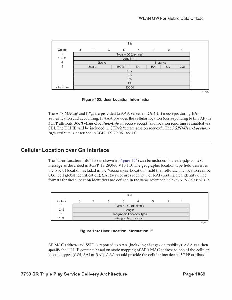
WLAN GW For Mobile Data Offload
7750 SR Triple Play Service Delivery Architecture Page 1869
Figure 153: User Location Information
The AP’s MAC@ and IP@ are provided to AAA server in RADIUS messages during EAP
authentication and accounting. If AAA provides the cellular location (corresponding to this AP) in
3GPP attribute 3GPP-User-Location-Info in access-accept, and location reporting is enabled via
CLI. The ULI IE will be included in GTPv2 “create session request”. The 3GPP-User-Location-
Info attribute is described in 3GPP TS 29.061 v9.3.0.
Cellular Location over Gn Interface
The “User Location Info” IE (as shown in Figure 154) can be included in create-pdp-context
message as described in 3GPP TS 29.060 V10.1.0. The geographic location type field describes
the type of location included in the “Geographic Location” field that follows. The location can be
CGI (cell global identification), SAI (service area identity), or RAI (routing area identity). The
formats for these location identifiers are defined in the same reference 3GPP TS 29.060 V10.1.0.
Figure 154: User Location Information IE
AP MAC address and SSID is reported to AAA (including changes on mobility). AAA can then
specify the ULI IE contents based on static mapping of AP’s MAC address to one of the cellular
location types (CGI, SAI or RAI). AAA should provide the cellular location in 3GPP attribute
al_0412
Bits
Type = 86 (decimal)
Length = n
Octets
1
2 of 3
4
5
x to (n+4)
Spare
Spare ECGI TAI
CGI
SAI
RAI
TAI
ECGI
RAI SAI CGI
Instance
8 7 6 5 4 3 2 1
al_0413
Bits
Type = 152 (decimal)
Length
Geographic Location Type
Geographic Location
Octets
1
2–3
4
5–m
8 7 6 5 4 3 2 1
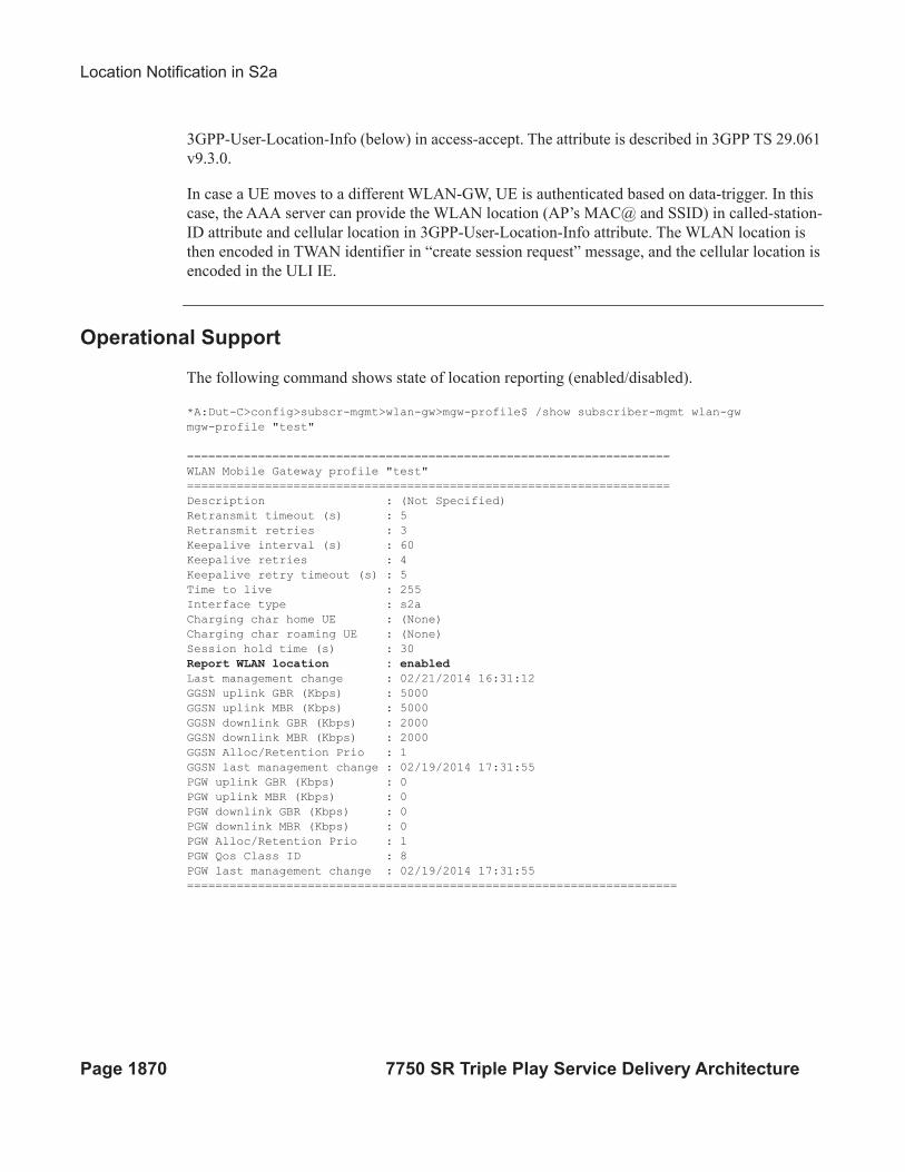
Location Notification in S2a
Page 1870 7750 SR Triple Play Service Delivery Architecture
3GPP-User-Location-Info (below) in access-accept. The attribute is described in 3GPP TS 29.061
v9.3.0.
In case a UE moves to a different WLAN-GW, UE is authenticated based on data-trigger. In this
case, the AAA server can provide the WLAN location (AP’s MAC@ and SSID) in called-station-
ID attribute and cellular location in 3GPP-User-Location-Info attribute. The WLAN location is
then encoded in TWAN identifier in “create session request” message, and the cellular location is
encoded in the ULI IE.
Operational Support
The following command shows state of location reporting (enabled/disabled).
*A:Dut-C>config>subscr-mgmt>wlan-gw>mgw-profile$ /show subscriber-mgmt wlan-gw
mgw-profile "test"
====================================================================
WLAN Mobile Gateway profile "test"
====================================================================
Description : (Not Specified)
Retransmit timeout (s) : 5
Retransmit retries : 3
Keepalive interval (s) : 60
Keepalive retries : 4
Keepalive retry timeout (s) : 5
Time to live : 255
Interface type : s2a
Charging char home UE : (None)
Charging char roaming UE : (None)
Session hold time (s) : 30
Report WLAN location : enabled
Last management change : 02/21/2014 16:31:12
GGSN uplink GBR (Kbps) : 5000
GGSN uplink MBR (Kbps) : 5000
GGSN downlink GBR (Kbps) : 2000
GGSN downlink MBR (Kbps) : 2000
GGSN Alloc/Retention Prio : 1
GGSN last management change : 02/19/2014 17:31:55
PGW uplink GBR (Kbps) : 0
PGW uplink MBR (Kbps) : 0
PGW downlink GBR (Kbps) : 0
PGW downlink MBR (Kbps) : 0
PGW Alloc/Retention Prio : 1
PGW Qos Class ID : 8
PGW last management change : 02/19/2014 17:31:55
=====================================================================
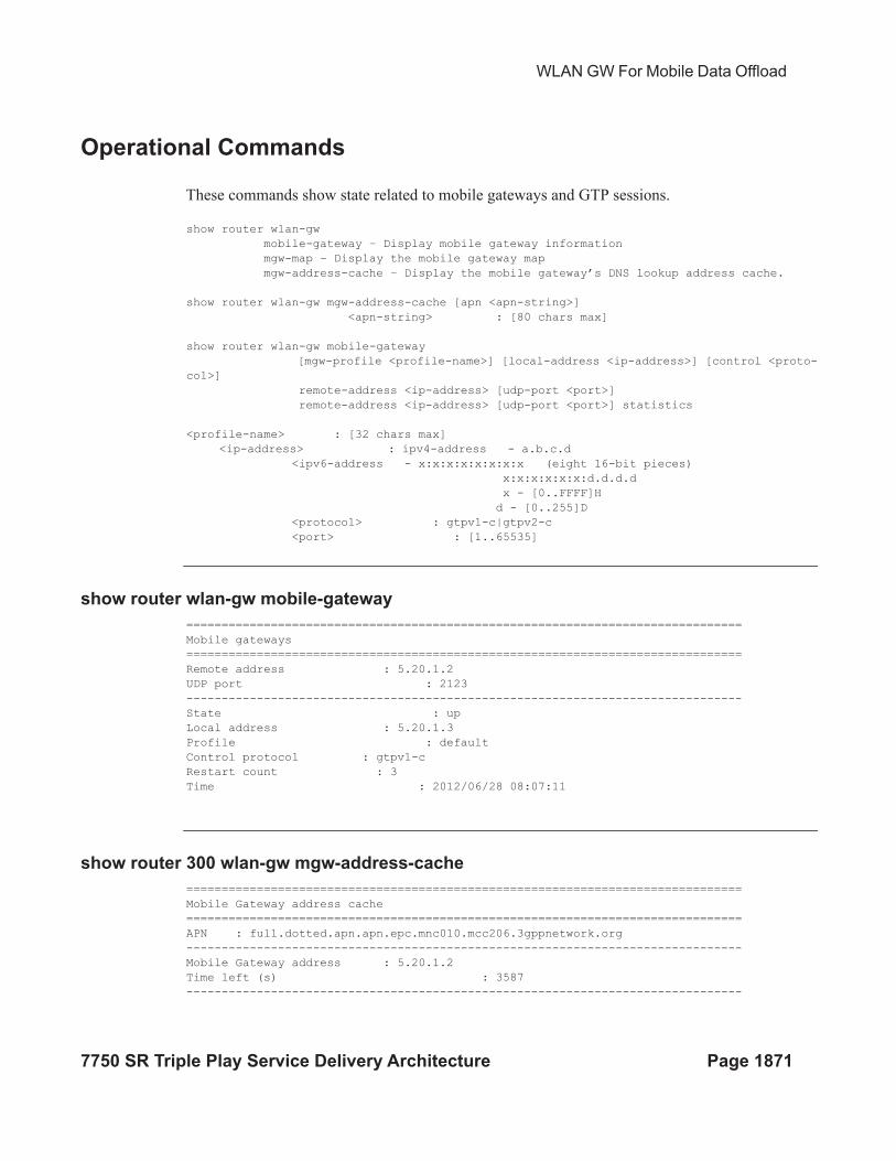
WLAN GW For Mobile Data Offload
7750 SR Triple Play Service Delivery Architecture Page 1871
Operational Commands
These commands show state related to mobile gateways and GTP sessions.
show router wlan-gw
mobile-gateway – Display mobile gateway information
mgw-map – Display the mobile gateway map
mgw-address-cache – Display the mobile gateway’s DNS lookup address cache.
show router wlan-gw mgw-address-cache [apn <apn-string>]
<apn-string> : [80 chars max]
show router wlan-gw mobile-gateway
[mgw-profile <profile-name>] [local-address <ip-address>] [control <proto-
col>]
remote-address <ip-address> [udp-port <port>]
remote-address <ip-address> [udp-port <port>] statistics
<profile-name> : [32 chars max]
<ip-address> : ipv4-address - a.b.c.d
<ipv6-address - x:x:x:x:x:x:x:x (eight 16-bit pieces)
x:x:x:x:x:x:d.d.d.d
x - [0..FFFF]H
d - [0..255]D
<protocol> : gtpv1-c|gtpv2-c
<port> : [1..65535]
show router wlan-gw mobile-gateway
===============================================================================
Mobile gateways
===============================================================================
Remote address : 5.20.1.2
UDP port : 2123
-------------------------------------------------------------------------------
State : up
Local address : 5.20.1.3
Profile : default
Control protocol : gtpv1-c
Restart count : 3
Time : 2012/06/28 08:07:11
show router 300 wlan-gw mgw-address-cache
===============================================================================
Mobile Gateway address cache
===============================================================================
APN : full.dotted.apn.apn.epc.mnc010.mcc206.3gppnetwork.org
-------------------------------------------------------------------------------
Mobile Gateway address : 5.20.1.2
Time left (s) : 3587
-------------------------------------------------------------------------------
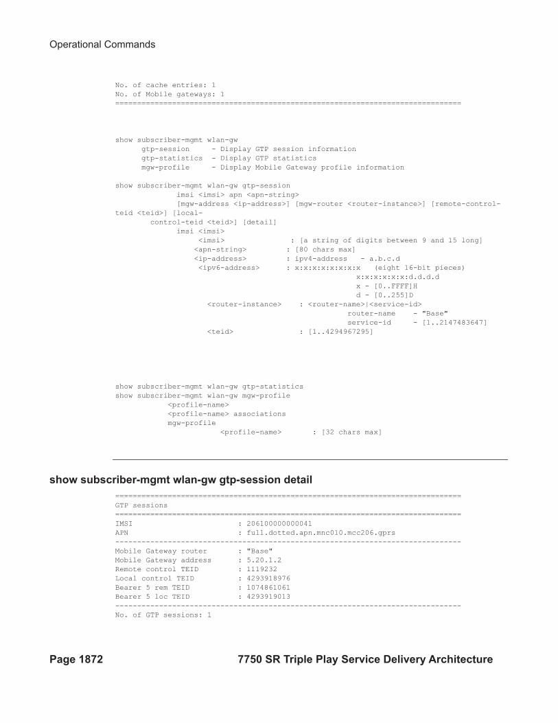
Operational Commands
Page 1872 7750 SR Triple Play Service Delivery Architecture
No. of cache entries: 1
No. of Mobile gateways: 1
===============================================================================
show subscriber-mgmt wlan-gw
gtp-session - Display GTP session information
gtp-statistics - Display GTP statistics
mgw-profile - Display Mobile Gateway profile information
show subscriber-mgmt wlan-gw gtp-session
imsi <imsi> apn <apn-string>
[mgw-address <ip-address>] [mgw-router <router-instance>] [remote-control-
teid <teid>] [local-
control-teid <teid>] [detail]
imsi <imsi>
<imsi> : [a string of digits between 9 and 15 long]
<apn-string> : [80 chars max]
<ip-address> : ipv4-address - a.b.c.d
<ipv6-address> : x:x:x:x:x:x:x:x (eight 16-bit pieces)
x:x:x:x:x:x:d.d.d.d
x - [0..FFFF]H
d - [0..255]D
<router-instance> : <router-name>|<service-id>
router-name - "Base"
service-id - [1..2147483647]
<teid> : [1..4294967295]
show subscriber-mgmt wlan-gw gtp-statistics
show subscriber-mgmt wlan-gw mgw-profile
<profile-name>
<profile-name> associations
mgw-profile
<profile-name> : [32 chars max]
show subscriber-mgmt wlan-gw gtp-session detail
===============================================================================
GTP sessions
===============================================================================
IMSI : 206100000000041
APN : full.dotted.apn.mnc010.mcc206.gprs
-------------------------------------------------------------------------------
Mobile Gateway router : "Base"
Mobile Gateway address : 5.20.1.2
Remote control TEID : 1119232
Local control TEID : 4293918976
Bearer 5 rem TEID : 1074861061
Bearer 5 loc TEID : 4293919013
-------------------------------------------------------------------------------
No. of GTP sessions: 1
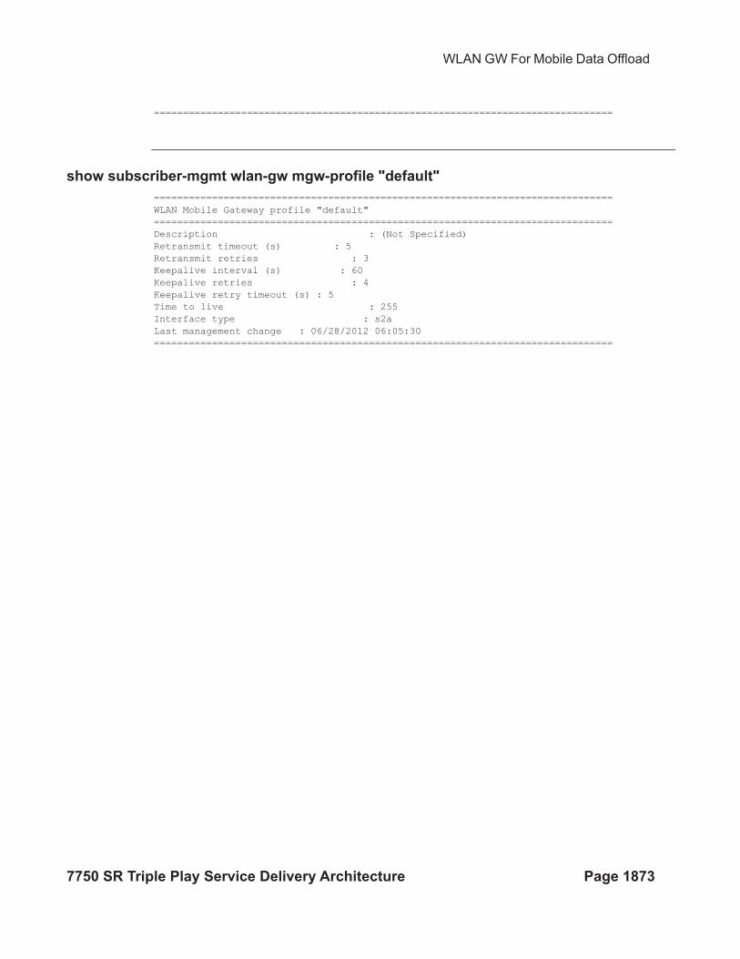
WLAN GW For Mobile Data Offload
7750 SR Triple Play Service Delivery Architecture Page 1873
===============================================================================
show subscriber-mgmt wlan-gw mgw-profile "default"
===============================================================================
WLAN Mobile Gateway profile "default"
===============================================================================
Description : (Not Specified)
Retransmit timeout (s) : 5
Retransmit retries : 3
Keepalive interval (s) : 60
Keepalive retries : 4
Keepalive retry timeout (s) : 5
Time to live : 255
Interface type : s2a
Last management change : 06/28/2012 06:05:30
===============================================================================
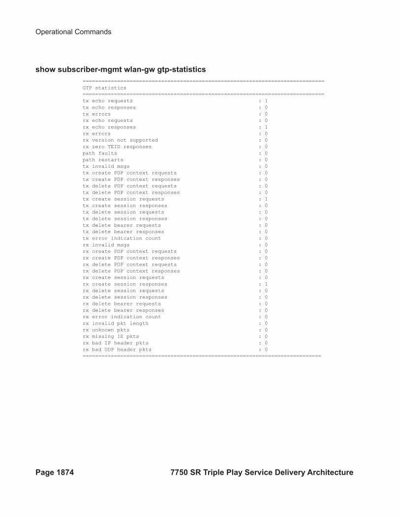
Operational Commands
Page 1874 7750 SR Triple Play Service Delivery Architecture
show subscriber-mgmt wlan-gw gtp-statistics
=============================================================================
GTP statistics
=============================================================================
tx echo requests : 1
tx echo responses : 0
tx errors : 0
rx echo requests : 0
rx echo responses : 1
rx errors : 0
rx version not supported : 0
rx zero TEID responses : 0
path faults : 0
path restarts : 0
tx invalid msgs : 0
tx create PDP context requests : 0
tx create PDP context responses : 0
tx delete PDP context requests : 0
tx delete PDP context responses : 0
tx create session requests : 1
tx create session responses : 0
tx delete session requests : 0
tx delete session responses : 0
tx delete bearer requests : 0
tx delete bearer responses : 0
tx error indication count : 0
rx invalid msgs : 0
rx create PDP context requests : 0
rx create PDP context responses : 0
rx delete PDP context requests : 0
rx delete PDP context responses : 0
rx create session requests : 0
rx create session responses : 1
rx delete session requests : 0
rx delete session responses : 0
rx delete bearer requests : 0
rx delete bearer responses : 0
rx error indication count : 0
rx invalid pkt length : 0
rx unknown pkts : 0
rx missing IE pkts : 0
rx bad IP header pkts : 0
rx bad UDP header pkts : 0
============================================================================
WLAN GW For Mobile Data Offload
7750 SR Triple Play Service Delivery Architecture Page 1875
Migrant User Support
“Migrant users” are UEs that connect to an SSID, but move out of the range of the access-point
before initiating or completing authentication. For open-SSIDs, a migrant user may stay in the
range of the access-point just enough to get a DHCP lease from the WLAN-GW. In real WIFI
deployments with portal authentication, it has been observed that a large percentage of users are
migrant, such as get a DHCP lease but do not initiate or complete authentication. Prior to this
feature, an ESM host is created when DHCP completes. This results in consumption of resources
on both CPM and IOM, limiting the ESM scale and performance for fully authenticated active
users. This feature adds support to only create an ESM host after a user has been fully
authenticated, either via web portal or with a AAA server based on completing EAP exchange. In
addition, with this feature L2-aware NAPT is enabled on the ISA, such that each UE gets the same
shared configured inside IP@ from the ISA via DHCP. Until a user is authenticated, forwarding of
user traffic is constrained (via policy) to only access DNS and portal servers. Each user is
allocated a small number of configured NAT outside ports to minimize public IP address
consumption for unauthenticated users. Once the user is successfully authenticated, as indicated
via a RADIUS COA on successful portal authentication, an ESM host is created, and the L2-aware
NAT is applied via a normal per-subscriber NAT policy. The inside IP address of the user does not
change. The outside IP pool used is as per the NAT policy, and the L2-aware NAT could be 1:1 or
NAPT with larger number of outside ports than in the un-authenticated phase. If a user is already
pre-authenticated (for example, if RADIUS server remembers the MAC@ of the UE from
previous successful portal authentication), then the initial access-accept from RADIUS will
trigger the creation of the ESM host.
Migrant user support is only applicable to EAP based closed SSIDs when RADIUS-proxy is not
enabled on WLAN-GW. This is described in Migrant User Support with EAP Authentication on
page 1877.
Migrant User Support with Portal-Authentication
Page 1876 7750 SR Triple Play Service Delivery Architecture
Migrant User Support with Portal-Authentication
DHCP
Based on DHCP and L2 NAT configuration on the ISA, IP address is assigned to the user via
DHCP. A different DHCP lease-time can be configured for an un-authenticated user and an
authenticated user for which an ESM host has been created. DHCP return options, for example,
DNS and NBNS server addresses can be configured. This configuration can be per wlan-gw group
interface or per VLAN range (where a VLAN tag corresponds to an SSID). Once the DHCP ACK
is sent back to the UE from the ISA, the UE will be created on the ISA in “migrant (or
unauthenticated) state”. ARP requests coming from the UE in migrant state will be responded to
from the ISA. The authentication to RADIUS is triggered on receiving first L3 data-packet as
opposed to on DHCP DISCOVER.
Authentication and Forwarding
The authentication is initiated from RADIUS client on the ISA anchoring the user, based on an
isa-radius-policy (configured under aaa) and specified on the wlan-gw group-interface. The initial
access-accept from RADIUS can indicate if a user needs to be portal authenticated or is a pre-
authenticated user. The indication is based on inclusion of a “redirect policy” applicable to the
user, in a VSA (Alc-Wlan-Portal-Redirect, type = string). The access-accept can also include a
redirect URL VSA (Alc-Wlan-Portal-Url, type = string) for the user. An empty Alc-Wlan-
Portal_redirect VSA forces the use of locally configured redirect policy. Also, if neither of the
above two VSAs are included, then this indicates a “pre-authenticated user”, and an ESM host is
created for the subscriber with subscriber-profile and other subscriber configuration from access-
accept, and from here normal ESM based forwarding occurs for the subscriber.
However, if a user needs portal authentication (as indicated in access-accept), then while the user
is pending authentication, forwarding is restricted to DNS and portal servers via the redirect
policy. The redirect policy is an IP ACL that restricts forwarding based on IP destination,
destination port, and protocol, and also specifies http-redirect for http traffic that does not match
any of the forwarding rules. The URL for re-direct is configured in the redirect policy or can be
provided in authentication-accept. A maximum of 16 redirect policies can be created in the
system, with a maximum of 64 forward rules across all redirect policies. During this
“authentication pending” phase all forwarded traffic is subjected to L2-aware NAT on the ISA.
The NAT policy to use for these users can be configured on the wlan-gw interface or per VLAN
range under the wlan-gw interface. After an access-accept has been received from RADIUS for
such a user, the next http packet triggers a redirect function from the ISA, and an http 302 is sent to
the client. The redirect can be configured to append original-URL, subscriber’s MAC address and
IP address to the redirect URL sent back in http 302. The client presents its credentials to the
portal and once it is successfully authenticated, a COA is generated from the RADIUS server
WLAN GW For Mobile Data Offload
7750 SR Triple Play Service Delivery Architecture Page 1877
(triggered by the portal). The COA message triggers creation of an ESM host with the subscriber
configuration contained in the COA such as subscriber-profile, SLA-profile, NAT-profile and
application-profile. From this point normal ESM based forwarding occurs for the subscriber.
The configuration related to migrant users is shown on page 1879.
Migrant User Support with EAP Authentication
Migrant user support can only be used for closed SSIDs when there is no RADIUS-proxy
configured on WLAN-GW. If no RADIUS proxy is configured, then initial RADIUS request
carrying EAP from the AP is normally forwarded to a RADIUS server. The RADIUS exchange is
between AP and the AAA server, and no information from EAP authentication is cached on the
WLAN-GW. The subsequent DHCP DISCOVER after successful EAP authentication is received
on the ISA. However, for subscriber that needs to be GTP tunneled to PGW/GGSN, the DHCP is
forwarded to the CPM, where it triggers a RADIUS authorization. RADIUS correlates the MAC
address with calling-station-id from EAP authentication for the user. GTP tunnel initiation, and
ESM host creation then follows after receiving an access-accept. However, for a “local-breakout”
subscriber DHCP and L2-aware NAT is handled on the ISA (as in the case for migrant users with
portal based authentication). Shared inside IP address can be handed out to each subscriber. The
first L3 packet triggers MAC address based RADIUS authorization from the ISA. RADIUS server
can correlate the EAP authentication with the MAC address of the user and send an access-accept.
This triggers ESM host creation as normal.
For closed SSIDs with EAP authentication, if a RADIUS proxy function is configured on WLAN-
GW, then the initial EAP authentication from the AP is processed by the RADIUS-proxy on the
CPM, and is forwarded to the RADIUS server based on configured authentication policy. Based
on authentication response, ESM host creation with local DHCP address assignment or GTP
tunnel initiation proceeds as usual.
Data Triggered Subscriber Creation
With data-triggered-ue-creation configured under wlan-gw group interface or per VLAN range
(such as, per one or more SSIDs), the first UDP or TCP packet received on WLAN-GW ISA from
an unknown subscriber (with no prior state, such as an unknown MAC address) will trigger
RADIUS authentication from the ISA. The authentication is based on configured isa-radius-policy
(under aaa context). If RADIUS authentication succeeds, then ESM host is created from the CPM.
The ESM host can get deleted based on idle-timeout. Data-triggered authentication and subscriber
creation enables stateless inter WLAN-GW redundancy, as shown in Figure 155. If the AP is
configured with a backup WLAN-GW address (or FQDN), it can tunnel subscriber traffic to the
backup WLAN-GW, when it detects failure of the primary WLAN-GW (based on periodic
liveness detection). With “data-triggered-ue-creation” configured, the first data packet results in
authentication and ESM host creation on the backup WLAN-GW. If the subscriber had obtained
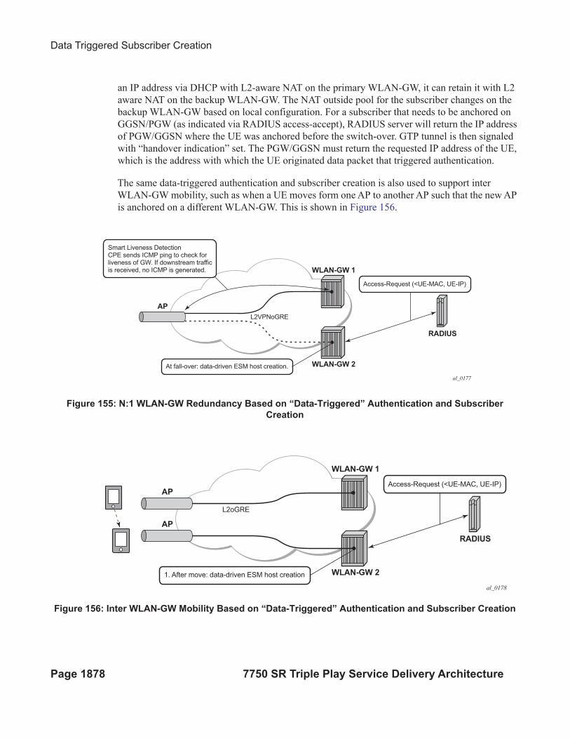
Data Triggered Subscriber Creation
Page 1878 7750 SR Triple Play Service Delivery Architecture
an IP address via DHCP with L2-aware NAT on the primary WLAN-GW, it can retain it with L2
aware NAT on the backup WLAN-GW. The NAT outside pool for the subscriber changes on the
backup WLAN-GW based on local configuration. For a subscriber that needs to be anchored on
GGSN/PGW (as indicated via RADIUS access-accept), RADIUS server will return the IP address
of PGW/GGSN where the UE was anchored before the switch-over. GTP tunnel is then signaled
with “handover indication” set. The PGW/GGSN must return the requested IP address of the UE,
which is the address with which the UE originated data packet that triggered authentication.
The same data-triggered authentication and subscriber creation is also used to support inter
WLAN-GW mobility, such as when a UE moves form one AP to another AP such that the new AP
is anchored on a different WLAN-GW. This is shown in Figure 156.
Figure 155: N:1 WLAN-GW Redundancy Based on “Data-Triggered” Authentication and Subscriber
Creation
Figure 156: Inter WLAN-GW Mobility Based on “Data-Triggered” Authentication and Subscriber Creation
WLAN-GW 1
AP
L2VPNoGRE
Smart Liveness DetectionCPE sends ICMP ping to check forliveness of GW. If downstream trafficis received, no ICMP is generated.
Access-Request (<UE-MAC, UE-IP)
At fall-over: data-driven ESM host creation. WLAN-GW 2
RADIUS
al_0177
WLAN-GW 1
AP
AP
L2oGRE
Access-Request (<UE-MAC, UE-IP)
1. After move: data-driven ESM host creation WLAN-GW 2
RADIUS
al_0178
WLAN GW For Mobile Data Offload
7750 SR Triple Play Service Delivery Architecture Page 1879
output
The following output displays the configuration for migrant user support and “data-triggered”
subscriber creation.
#------------------------------------------------------
NAT configuration for migrant and authenticated users
#------------------------------------------------------
service
vprn 300 customer 1 create
nat
inside
l2-aware
address 21.1.1.1/16
exit
exit
outside
pool "migrant_outside_pool" nat-group 1 type wlan-gw-anchor create
address-range 22.22.0.0 22.22.0.255 create
exit
no shutdown
exit
pool "wifi_outside_pool" nat-group 1 type l2-aware create
address-range 22.0.0.0 22.0.0.255 create
exit
no shutdown
exit
exit
exit
exit
nat
nat-policy "migrant_nat_300" create
pool "migrant_outside_pool" router 300
timeouts
tcp-established min 1
exit
exit
nat-policy "wifi_nat_300" create
pool "wifi_outside_pool" router 300
exit
exit
#--------------------------------------------------------------------------------
echo "AAA Configuration" - ISA-RADIUS-Policy for authentication from WLAN-GW ISA
#--------------------------------------------------------------------------------
aaa
isa-radius-policy "wifi_isa_radius" create
description "Default authentication policy for migrant users"
password "i2KzVe9XPxgy4KN2UEIf6jKeMT3X4mT6JcUmnnPZIrw" hash2
servers
router "Base"
source-address-range 100.100.100.4
server 1 create
Data Triggered Subscriber Creation
Page 1880 7750 SR Triple Play Service Delivery Architecture
authentication
coa
ip-address 100.100.100.2
secret "ABIQRobhHXzq13ycwqS74FSrj.OdTwh5IdjhRB.yAF." hash2
no shutdown
exit
exit
exit
radius-server-policy "radius_server_policy" create
servers
router "Base"
server 1 name "radius_server"
exit
exit
exit
#--------------------------------------------------
echo "Subscriber-mgmt Configuration" - Redirect Policy
#--------------------------------------------------
subscriber-mgmt
http-redirect-policy "migrant_redirect" create
url "portal.ipdtest.alcatel-lucent.com:8081/start/?mac=$MAC&url=$URL&ip=$IP"
portal-hold-time 10
forward-entries
dst-ip 8.8.8.1 protocol tcp dst-port 8081
dst-ip 8.8.8.7 protocol tcp dst-port 8007
dst-ip 8.8.8.8 protocol udp dst-port 53
exit
exit
exit
service
#----------------------------------------------------------------
echo "migrant user configuration under wlan-gw group interface”
#---------------------------------------------------------------
vprn 300 customer 1 create
subscriber-interface "ies-4-20.1.1.1" create
address 20.1.1.1/16
group-interface "grp-vprn_ue-2/1/2:51" wlangw create
sap-parameters
sub-sla-mgmt
def-sla-profile "slaprof_1"
def-sub-profile "subprof_1"
sub-ident-policy "identprof"
exit
exit
dhcp
proxy-server
emulated-server 20.1.1.1
no shutdown
exit
trusted
lease-populate 32767
user-db "radius_ludb"
no shutdown
exit
WLAN GW For Mobile Data Offload
7750 SR Triple Play Service Delivery Architecture Page 1881
host-connectivity-verify interval 1000
wlan-gw
gw-address 50.1.1.4
mobility
hold-time 0
trigger data iapp
exit
router 50
wlan-gw-group 1
vlan-tag-ranges
range start 100 end 100
authentication
authentication-policy "wifi_isa_radius"
exit
data-triggered-ue-creation
dhcp
l2-aware-ip-address 21.1.1.2
primary-dns 130.1.1.1
secondary-dns 131.1.1.1
no shutdown
exit
nat-policy "migrant_nat_4"
exit
exit
no shutdown
exit
exit
exit
exit
Distributed Subscriber Management (DSM)
Page 1882 7750 SR Triple Play Service Delivery Architecture
Distributed Subscriber Management (DSM)
With this feature, once the UE is successfully authenticated (portal, auto-signed-in, or EAP), the
corresponding subscriber can be created on the anchor ISA, and both control plane and forwarding
plane for the subscriber are handled on the ISA. This mode of subscriber management is
henceforth referred to as Distributed Subscriber Management (DSM).
Prior to this feature, only ESM is supported for WLAN UEs, where the ESM host state is created
on the IOM/IMMs from the CPM (triggered by the ISA on successful authentication). With ESM,
the initial DHCP process and authentication could be triggered from the ISA (based on a per
VLAN-range configuration for DHCP) under the group-interface with of type wlangw. However,
control plane operations after the ESM host creation (such as accounting and DHCP renews) are
handled on the CPM.
With DSM, in addition to initial DHCP and authentication, once the subscriber state exists on the
anchor ISA, accounting and DHCP renews are also handled from the anchor ISA for the UE. This
allows a higher UE scale and better control plane performance (including DHCP transactions per
second, rate of authentications, and web redirects) due to load-balancing amongst set of ISAs in
the WLAN-GW group. With DSM, the UE data-plane functions (such as per UE IP filtering,
ingress/egress policing, legal intercept, per UE counters, and web-redirect) are performed on the
ISA.
The decision to create an authenticated UE as an ESM or DSM UE can be controlled from
RADIUS via inclusion of Alc-Wlan-Ue-Creation-Type VSA. The VSA can be included in access-
accept for a UE that is auto-signed-in (for example, it does not need web redirect to portal), or in a
COA message triggered to remove web redirect for a UE after successful portal authentication.
The VSA is described in the RADIUS guide. If Alc-Wlan-Ue-Creation-Type is not present in
access-accept (for auto-signed UE) or in the COA message (for UE creation of portal
authenticated UE), then the UE is created as an ESM host. In this release DSM is not supported for
dual-stack UEs or UEs which require a GTP host. If Alc-Wlan-Ue-Creation-Type indicates a DSM
UE then any IPv6 or GTP related parameters in access-accept or COA will be ignored, and the UE
will be created as a DSM host. Alc-Wlan-Ue-Creation-Type cannot be changed mid-session via
COA. A COA containing Alc-Wlan-Ue-Creation-Type for an existing UE does not result in any
change of state, and is NACK’ed.
WLAN GW For Mobile Data Offload
7750 SR Triple Play Service Delivery Architecture Page 1883
DHCP
Based on DHCP and L2 NAT configuration on the ISA, the configured IP address (l2-aware-ip-
address configured under vlan-range or default vlan-range) is assigned to the user via DHCP. A
different DHCP lease-time can be configured for an un-authenticated and an authenticated user for
which an ESM or DSM host has been created. DHCP return options, for example, DNS and
NBNS server addresses can be configured. This configuration can be per soft-wlan-gw group
interface (by explicitly configuring it under vlan-range default), or per VLAN range (where a
VLAN tag corresponds to an SSID). By default, for open SSIDs, DHCP DORA is completed, and
authentication request is is sent to AAA server only on reception of the first Layer 3 packet.
However, with a authenticate-on-dhcp command configured under vlan-range (default or
specific range), authentication can be triggered on received DHCP DISCOVER or REQUEST
when no UE state is present. If UE anchoring on GGSN/PGW is required, then authenticate-on-
dhcp must be enabled, since the decision to setup GTP tunnel (in which case the IP@ for the UE
comes from the GGSN/PGW) is based on RADIUS response.
Authentication and Accounting
The authentication is initiated from RADIUS client on the ISA anchoring the user, based on an
isa-radius-policy (configured under aaa) and specified on the wlan-gw group-interface. This
support exists in prior releases and is described in Authentication and Forwarding on page 1876.
The auth-policy can contain up to ten servers, five of which can be for authentication and all ten
can be COA servers.
In order to generate accounting updates for DSM UEs, an accounting policy (type isa-radius-
policy) must be configured under the aaa node and specified under vlan-range (default or
specific range) on the wlan-gw interface. Accounting for DSM UEs includes accounting-start,
accounting-stop and interim-updates. Interim-update interval is configurable under vlan-range
on wlan-gw interface. The user-name format to be included in RADIUS messages is configurable
in the auth-policy and accounting-policy via the user-name-format command. By default, the
user-name contains the UE MAC address, but can be configured to include the UEs MAC address
and IP address, or circuit-id or DHCP vendor options. If authenticate-on-dhcp is enabled, then
the IP address for the UE is not known prior to authentication, and, if the user-name is configured
to contain both MAC and IP address, then only the MAC address will be included.
The accounting-policy can be configured with attributes to be included in the accounting
messages. The details of the attributes are covered in the 7750 SR-OS RADIUS Attributes
Reference Guide. The attributes are included here for reference.
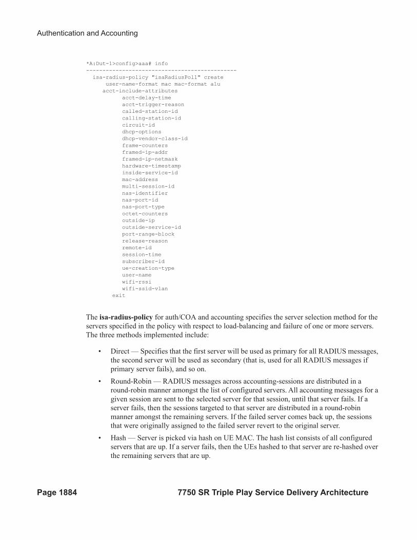
Authentication and Accounting
Page 1884 7750 SR Triple Play Service Delivery Architecture
*A:Dut-1>config>aaa# info
----------------------------------------------
isa-radius-policy "isaRadiusPol1" create
user-name-format mac mac-format alu
acct-include-attributes
acct-delay-time
acct-trigger-reason
called-station-id
calling-station-id
circuit-id
dhcp-options
dhcp-vendor-class-id
frame-counters
framed-ip-addr
framed-ip-netmask
hardware-timestamp
inside-service-id
mac-address
multi-session-id
nas-identifier
nas-port-id
nas-port-type
octet-counters
outside-ip
outside-service-id
port-range-block
release-reason
remote-id
session-time
subscriber-id
ue-creation-type
user-name
wifi-rssi
wifi-ssid-vlan
exit
The isa-radius-policy for auth/COA and accounting specifies the server selection method for the
servers specified in the policy with respect to load-balancing and failure of one or more servers.
The three methods implemented include:
• Direct — Specifies that the first server will be used as primary for all RADIUS messages,
the second server will be used as secondary (that is, used for all RADIUS messages if
primary server fails), and so on.
• Round-Robin — RADIUS messages across accounting-sessions are distributed in a
round-robin manner amongst the list of configured servers. All accounting messages for a
given session are sent to the selected server for that session, until that server fails. If a
server fails, then the sessions targeted to that server are distributed in a round-robin
manner amongst the remaining servers. If the failed server comes back up, the sessions
that were originally assigned to the failed server revert to the original server.
• Hash — Server is picked via hash on UE MAC. The hash list consists of all configured
servers that are up. If a server fails, then the UEs hashed to that server are re-hashed over
the remaining servers that are up.
WLAN GW For Mobile Data Offload
7750 SR Triple Play Service Delivery Architecture Page 1885
If a response is not received for a RADIUS message from a particular server for a configurable
timeout value (per server), and the time elapsed since the last packet received from this RADIUS
server is longer than this configured timeout value, then the server is deemed to be down.
Periodically an accounting-on message is sent to a server that is marked as down, to probe if it has
become responsive. If a response is received then the server is marked as up.
*A:Dut-1>config>aaa# info
isa-radius-policy "isaRadiusPol1" create
nas-ip-address-origin system-ip
password "6mNsKxvTe.0.nNCTIpGFcu.rr/qtdijazQ3ED8WAFfk" hash2
user-name-format mac mac-format alu release-reason
servers
access-algorithm hash-based
retry 3
router "Base"
source-address-range 81.1.0.1
timeout sec 5
server 1 create
accounting port 1813
authentication port 1812
coa port 3799
ip-address 10.13.0.2
secret "3BmWbBfDO38hPY8DtLFn8bYDBaduy6w.ogeSUsouoHc" hash2
no shutdown
exit
exit
exit
----------------------------------------------
*A:Dut-1>config>aaa#
DSM Data-Plane
In this release NAT on the anchor ISA is required for forwarding of traffic to/from a DSM UE.
There is no UE state in the IOM/IMM for a DSM UE. The downstream forwarding is based on
FIB lookup that should match a route corresponding to the NAT outside pool, and get the
downstream traffic to the right anchor ISA, where NAT is performed for the UE. The inside IP
address assigned to the UE is the configured l2-aware-ip-address on the vlan-range (default or
specific range) under wlan-gw interface. Therefore every UE corresponding to the default or
specific vlan-range will get the same inside IP@. The NAT is L2-aware, and uses UE MAC to de-
multiplex.
IP Filtering
Page 1886 7750 SR Triple Play Service Delivery Architecture
IP Filtering
Filtering based on protocol, destination IP, destination port or any combination is supported for
traffic to and from the UE. The match entries and corresponding actions can be specified within
the dsm-ip-filter which can be created in the subscriber-mgmt>wlan-gw>dsm context. The
filter can be associated with a vlan-range (default or specific vlan-range) on wlan-gw interface, in
which case all subscribers associated with the vlan-range will be associated with an instance of
this filter.
The supported filter actions include drop and forward. The first match will cause corresponding
action to be executed and no further match entries will be executed. In case there is no match or no
action configured for a match, configurable default action for the filter will be executed. The filter
can be overridden on a per UE basis via RADIUS access-accept or COA. The new VSA Alc-
Wlan-Dsm-Ip-Filter is defined for specifying the per UE filter from RADIUS. The VSA is defined
in the RADIUS guide.
A:system>config>subscr-mgmt>wlan-gw>dsm>dsm-ip-filter# info
----------------------------------------------
dsm-ip-filter “foo” create
default-action forward
entry 1 create
action drop
match protocol udp
dst-ip 203.0.113.0/32
dst-port eq 53
exit
exit
ipv6
default-action forward
entry 1 create
action drop
match protocol tcp
dst-ip 2001:db8::/120
dst-port eq 80
exit
exit
exit
----------------------------------------------
*A:vsim>config>service>vprn# info
----------------------------------------------
subscriber-interface "s1" create
group-interface "g1" wlangw create
wlan-gw
vlan-tag-ranges
range default
distributed-sub-mgmt
dsm-ip-filter “foo”
exit
exit
exit
WLAN GW For Mobile Data Offload
7750 SR Triple Play Service Delivery Architecture Page 1887
exit
----------------------------------------------
IP Filtering
Page 1888 7750 SR Triple Play Service Delivery Architecture
Policing
Per UE policing for both ingress and egress direction is supported. Policers can be created under
subscriber-mgmt>wlan-gw>dsm. The policers can be of type single-bucket (PIR) bandwidth
limiting or dual-bucket (PIR and CIR) bandwidth limiting. In this release only policer action
supported is permit-deny i.e. non-conformant traffic is dropped, as opposed to marked out-of-
profile. The administrative peak and committed rates and peak and committed burst sizes are
configurable. For single-bucket bandwidth policers, cir and cbs are not applicable, and only pir
and mbs are configurable.
*A:vsim>config>subscr-mgmt>wlan-gw>distributed-sub-mgmt>dsm-policer# info detail
----------------------------------------------
no description
action permit-deny
cbs 100
mbs 200
rate 1000 cir 500
The policers can be associated with a vlan-range (default or specific vlan-range) on wlan-gw
interface, in which case all subscribers associated with the vlan-range will be associated with an
instance of these policers. These ingress and egress policers can be overridden on per UE basis via
RADIUS access-accept or COA. The new VSAs Alc-Wlan-Dsm-Ingress-Policer and Alc-Wlan-
Dsm-Egress-Policer are defined for specifying the per UE policers from RADIUS. The VSAs are
defined in the 7750 SR-OS RADIUS Attributes Reference Guide. If the policers specified in
access-accept are not found the message is dropped. If the policers specified in COA are not
found, a NACK is sent back.
*A:vsim>config>service>vprn# info
----------------------------------------------
subscriber-interface "s1" create
group-interface "g1" wlangw create
wlan-gw
vlan-tag-ranges
range default
distributed-sub-mgmt
egress-policer "silver-egress"
ingress-policer "silver-ingress"
exit
exit
exit
exit
----------------------------------------------
WLAN GW For Mobile Data Offload
7750 SR Triple Play Service Delivery Architecture Page 1889
Lawful Intercept (LI)
LI can be triggered for a DSM UE LI via CLI or RADIUS, and is performed post-NAT. Only
routable encaps (IP/UDP/LI-shim) and IP-only mirror-dest are supported. A maximum of 2K
DSM UEs per-chassis can be under LI simultaneously. LI mirror dest (service in which mirrored
packets are injected) along with other required mirror information (mirror-dest type,
encapsulation-type e.g. ip-udp-shim, and encapsulation information e.g. IP and UDP header
information) is configurable. A DSM UE identified by its MAC address can be associated with the
mirror-dest (service in which mirrored packets for the host are injected) via li-source command.
For routable encapsulation (IP/UDP/LI-Shim), the session-id and transaction-id to be inserted in
the LI-Shim are configured under li-source.
A:Dut-1>config>mirror# info
----------------------------------------------
mirror-dest 60000 type ip-only create
encap
layer-3-encap ip-udp-shim create
gateway create
ip src 1.1.1.1 dest 2.2.2.2
udp src 2048 dest 2049
exit
exit
exit
no shutdown
exit
----------------------------------------------
A:Dut-1>config>li# info
----------------------------------------------
li-source 60000
wlan-gw
dsm-subscriber mac 00:00:00:07:02:03
intercept-id 10000
session-id 20000
exit
exit
no shutdown
exit
LI can be enabled or disabled from RADIUS via inclusion of the Alc-LI-Action VSA in access-
accept or COA. The Alc-LI-Destination VSA is required to indicate the mirror-dest service that the
DSM UE under LI is associated with. The Intercept-Id and Session-Id for a DSM UE can be
provided from RADIUS access-accept or COA via inclusion of Alc-LI-Intercept-Id and Alc-LI-
Session-Id VSAs. These LI related VSAs are described in the RADIUS guide.
Idle-Timeout and Session-Timeout Management
Page 1890 7750 SR Triple Play Service Delivery Architecture
Information for a particular li-source, and its associated mirror-dest can be shown via CLI.
Data-Triggered UE Creation
Similar to data-triggered UE creation with ESM, a DSM UE can also be created based on data-
triggered authentication discussed in Data Triggered Subscriber Creation on page 1877. The
decision to create ESM versus DSM UE is based on the value of RADIUS VSA Alc-Wlan-Ue-
Creation-Type present in the access-accept message. The data-triggered authentication and UE
creation if configured provides for WLAN-GW IOM redundancy. The DSM UE is created on the
standby ISA based on successful data-triggered authentication. Also, inter-chassis redundancy is
supported for DSM UE based on data-triggered authentication, and is identical to ESM (as
described in Data Triggered Subscriber Creation on page 1877.
Idle-Timeout and Session-Timeout Management
The per UE idle-timeout value can be provided in RADIUS access-accept or COA for a DSM UE
in standard Idle-Timeout attribute. The minimum idle-timeout allowed is 150 seconds. The idle-
timeout is enforced on the ISA for a DSM UE. If there is no data to/from a UE for up to idle-
timeout value, the UE is removed and accounting-stop is sent. Subsequently, if a UE re-associates
and connects to an open SSID on an AP, and has an IP address with a valid lease, then the first data
packet from the UE triggers authentication. Successful authentication results in creation of DSM
UE.
To improve idle-timeout behavior an optional SHCV check can be performed after idle-timeout
expires. This check verifies connectivity to all of the DHCP, DHCPv6 and /128 SLAAC addresses
using ARP and/or NDP. While the check is performed for every address, the result is applied to the
whole UE. The UE is only deleted when verification of all addresses fails. When at least one
connectivity verification succeeds the UE and all of the allocated addresses are kept and the idle-
timeout process is restarted.
The per UE session timeout value can be provided in RADIUS access-accept or COA in standard
Session-Timeout attribute. The value is interpreted as “absolute value”, and the UE is
unconditionally deleted regardless of activity. The minimum allowed value for session-timeout is
300 seconds.
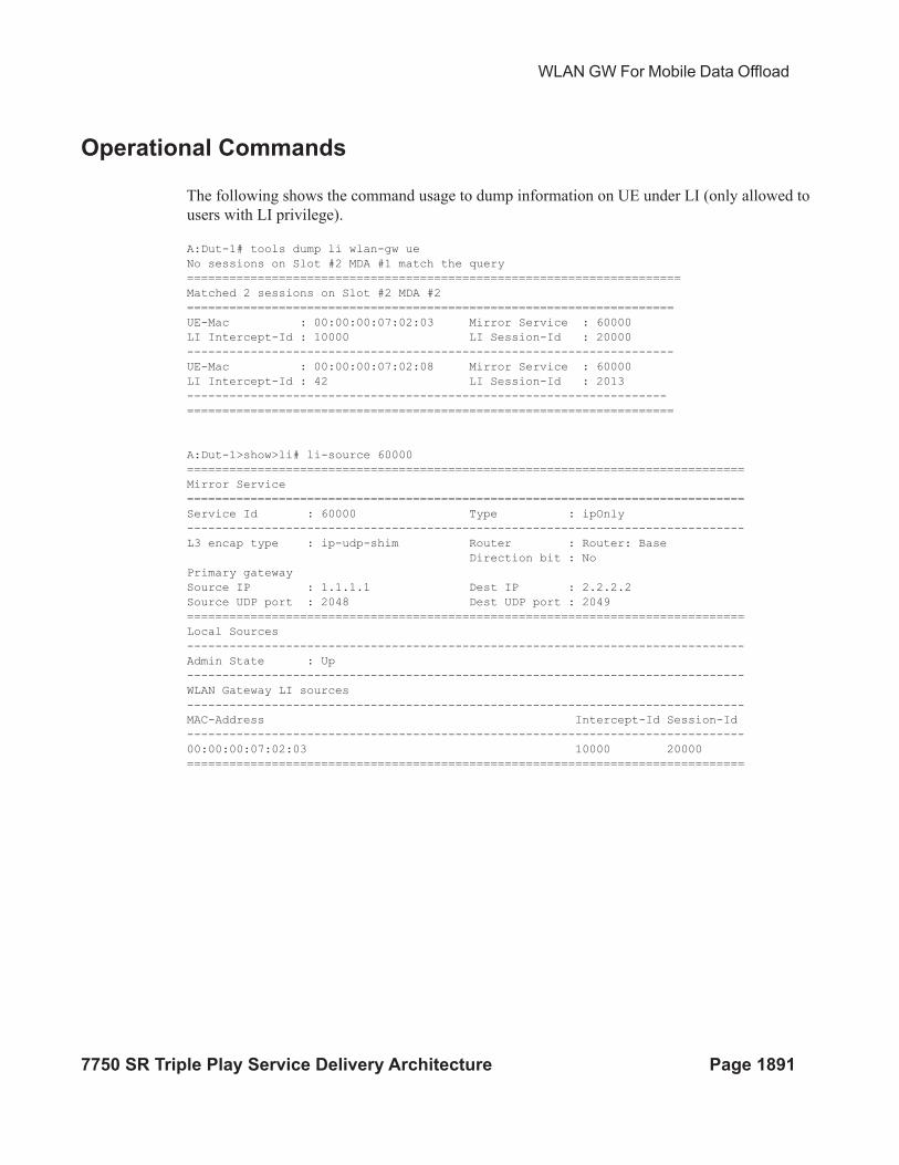
WLAN GW For Mobile Data Offload
7750 SR Triple Play Service Delivery Architecture Page 1891
Operational Commands
The following shows the command usage to dump information on UE under LI (only allowed to
users with LI privilege).
A:Dut-1# tools dump li wlan-gw ue
No sessions on Slot #2 MDA #1 match the query
======================================================================
Matched 2 sessions on Slot #2 MDA #2
=====================================================================
UE-Mac : 00:00:00:07:02:03 Mirror Service : 60000
LI Intercept-Id : 10000 LI Session-Id : 20000
---------------------------------------------------------------------
UE-Mac : 00:00:00:07:02:08 Mirror Service : 60000
LI Intercept-Id : 42 LI Session-Id : 2013
--------------------------------------------------------------------
=====================================================================
A:Dut-1>show>li# li-source 60000
===============================================================================
Mirror Service
===============================================================================
Service Id : 60000 Type : ipOnly
-------------------------------------------------------------------------------
L3 encap type : ip-udp-shim Router : Router: Base
Direction bit : No
Primary gateway
Source IP : 1.1.1.1 Dest IP : 2.2.2.2
Source UDP port : 2048 Dest UDP port : 2049
===============================================================================
Local Sources
-------------------------------------------------------------------------------
Admin State : Up
-------------------------------------------------------------------------------
WLAN Gateway LI sources
-------------------------------------------------------------------------------
MAC-Address Intercept-Id Session-Id
-------------------------------------------------------------------------------
00:00:00:07:02:03 10000 20000
===============================================================================
Pool Manager
Page 1892 7750 SR Triple Play Service Delivery Architecture
Pool Manager
To support allocations of unique IP addresses each ISA is assigned pools from a centralized pool
manager on the CPM. The ISA can subsequently assign addresses from these pools to UEs, but
this state is not synchronized back to the CPM. Different applications have different pools, for
example, SLAAC and DHCPv6 IA_NA cannot share a single pool. To support Wholesale/Retail
scenarios a pool-manager can be configured per subscriber-interface.
The allocation of additional pools and freeing up unused pools is based on configurable high and
low watermarks. When the usage level of all pools combined on an ISA reaches the high
watermark, a new pool is allocated. When the usage level of a single pool reaches zero and the
usage level of the other pools combined is below the low watermark, this pool is freed.
In the case of redundancy the pool manager will signal the pools that were allocated to the failed
ISA back to the new active ISA. These pools can no longer be used to allocate new addresses
because allocations are lost. However, these can still be used to forward traffic based on data-
triggered UE creation. This is supported both for IOM redundancy and Active/Standby WLAN-
GW redundancy. The new active ISA will also receive new pools that it can use for new
allocations.
The Pool Manager uses DHCPv6 Prefix Delegation to allocate pools to the ISAs. Each ISA is
represented by a separate DHCPv6 Client ID. These clients request fixed prefix sizes to
accommodate up to 64K UEs. In the case of Active/Standby redundancy the Pool Manager uses a
DHCPv6 Lease Query Message to retrieve the prefixes that were allocated to the failed WLAN-
GW. In order to identify the correct PD leases in the DHCPv6 server, a configurable virtual-
chassis-name is added to the DHCPv6 client-id, this value should be identical on both WLAN-
GWs and unique otherwise. The Pool Manager will always send out a DHCPv6 Relay message
and supports up to eight DHCPv6 servers.
A:system>config>subscr-mgmt>wlan-gw# info
----------------------------------------------
virtual-chassis-identifier "wlan_gw_pair"
----------------------------------------------
A:system>config>service>vprn>sub-if>wlan-gw# info
----------------------------------------------
pool-manager
watermarks high 85 low 66
wlan-gw-group 1
dhcpv6-client
server 2001:db8::1
lease-query max-retry 2
slaac
pool-name "pool_ue_pd_v6_slaac"
no shutdown
exit
ia-na
pool-name "pool_ue_pd_v6_dhcp6"
no shutdown
exit
exit
WLAN GW For Mobile Data Offload
7750 SR Triple Play Service Delivery Architecture Page 1893
exit
----------------------------------------------
DHCPv6 and SLAAC
DHCPv6 and SLAAC support can be configured per VLAN range. Authentication can be
triggered by a Router Solicit, DHCPv6 or DHCP packet but will only be triggered once per UE.
Each UE can be assigned a unique DHCPv6 IA_NA address (/128) or SLAAC prefix (/64) from
the ISA pools. The IPv6 pools are installed by the centralized pool manager. SLAAC privacy
extensions are supported and up to three /128 SLAAC addresses can be learned via either
Duplicate Address Detection or upstream data. Wholesale/retail is supported (IPv6 only) both via
radius and per vlan-range CLI, the applicable pool is selected from the retailer service. ESM and
DSM IPv6 are not supported in the same vlan-range context.
A:system>config>service>vprn>sub-if>grp-if>wlan-gw>ranges>range# info
----------------------------------------------
...
authenticate-on-dhcp
...
dhcp6
active-preferred-lifetime hrs 1
active-valid-lifetime hrs 1
no shutdown
exit
slaac
active-preferred-lifetime hrs 1
active-valid-lifetime hrs 1
no shutdown
exit
...
----------------------------------------------
Configuration of other DHCPv6/SLAAC parameters, such as server DUID and RA flags is taken
from the wlan-gw group-interface configuration. For DSM only the configuration of the wlan-gw
group interface applies, the retailer interface cannot override this configuration.
A:system>config>service>vprn>sub-if>grp-if>ipv6# info
----------------------------------------------
router-advertisements
other-stateful-configuration
prefix-options
autonomous
exit
exit
dhcp6
proxy-server
server-id duid-en string "example_duid"
exit
exit
DHCPv6 and SLAAC
Page 1894 7750 SR Triple Play Service Delivery Architecture
A subset of DHCPv6 options retrieved by the pool-manager in the PD process is reflected in
DHCPv6 towards the client. For IA_NA leases these are included in the associated DHCPv6
messages. For SLAAC allocations, the DNS option can be reflected in the Router Advertisement
and all options can also be reflected in a stateless DHCPv6 Information Reply message.
When using a captive portal, different valid/preferred lifetimes can be configured for authenticated
and un-authenticated UEs. The DHCPv6 lease time will be equal to the applied valid-lifetime and
can be extended via the regular renew process. SLAAC lifetime is equal to the applied valid-
lifetime and will be extended when sending an RA including the SLAAC prefix. To avoid infinite
SLAAC allocations, when sending an unsolicited RA, SHCV will be performed for all learned /
128 addresses. If SHCV fails for all addresses, the unsolicited RA will not contain the SLAAC
prefix and the SLAAC lifetime will not be extended.
In redundancy scenarios the new active ISA will migrate the leases in the old pools as soon as
possible to a lease in the new pools. For SLAAC this is done by sending an unsolicited RA to
deprecate the old prefix (lifetimes 0) and include a new prefix. For DHCPv6 this is done during
the first Renew, that will again deprecate the old address (lifetimes 0) and include a new address in
the same IA.
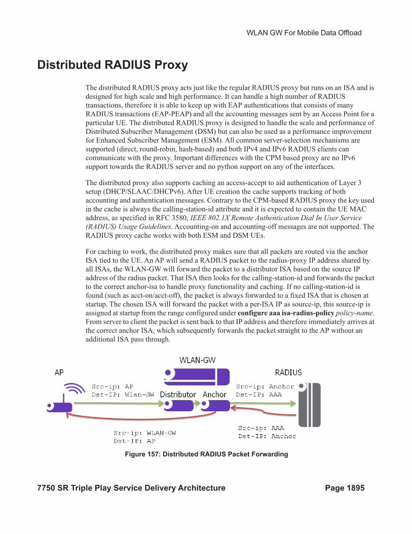
WLAN GW For Mobile Data Offload
7750 SR Triple Play Service Delivery Architecture Page 1895
Distributed RADIUS Proxy
The distributed RADIUS proxy acts just like the regular RADIUS proxy but runs on an ISA and is
designed for high scale and high performance. It can handle a high number of RADIUS
transactions, therefore it is able to keep up with EAP authentications that consists of many
RADIUS transactions (EAP-PEAP) and all the accounting messages sent by an Access Point for a
particular UE. The distributed RADIUS proxy is designed to handle the scale and performance of
Distributed Subscriber Management (DSM) but can also be used as a performance improvement
for Enhanced Subscriber Management (ESM). All common server-selection mechanisms are
supported (direct, round-robin, hash-based) and both IPv4 and IPv6 RADIUS clients can
communicate with the proxy. Important differences with the CPM based proxy are no IPv6
support towards the RADIUS server and no python support on any of the interfaces.
The distributed proxy also supports caching an access-accept to aid authentication of Layer 3
setup (DHCP/SLAAC/DHCPv6). After UE creation the cache supports tracking of both
accounting and authentication messages. Contrary to the CPM-based RADIUS proxy the key used
in the cache is always the calling-station-id attribute and it is expected to contain the UE MAC
address, as specified in RFC 3580, IEEE 802.1X Remote Authentication Dial In User Service
(RADIUS) Usage Guidelines. Accounting-on and accounting-off messages are not supported. The
RADIUS proxy cache works with both ESM and DSM UEs.
For caching to work, the distributed proxy makes sure that all packets are routed via the anchor
ISA tied to the UE. An AP will send a RADIUS packet to the radius-proxy IP address shared by
all ISAs, the WLAN-GW will forward the packet to a distributor ISA based on the source IP
address of the radius packet. That ISA then looks for the calling-station-id and forwards the packet
to the correct anchor-isa to handle proxy functionality and caching. If no calling-station-id is
found (such as acct-on/acct-off), the packet is always forwarded to a fixed ISA that is chosen at
startup. The chosen ISA will forward the packet with a per-ISA IP as source-ip, this source-ip is
assigned at startup from the range configured under configure aaa isa-radius-policy policy-name.
From server to client the packet is sent back to that IP address and therefore immediately arrives at
the correct anchor ISA, which subsequently forwards the packet straight to the AP without an
additional ISA pass through.
Figure 157: Distributed RADIUS Packet Forwarding

Distributed RADIUS Proxy
Page 1896 7750 SR Triple Play Service Delivery Architecture
The following is a distributed proxy configuration example.
#------------------------------------------------------
/configure service vprn 50 radius-proxy
----------------------------------------------
server "distributed_radius_proxy" purpose accounting authentication wlan-gw-group 1
create
cache
key packet-type request attribute-type 31
timeout min 5
no track-accounting
track-authentication accept
track-delete-hold-time 0
no shutdown
exit
default-accounting-server-policy "wlangw_isa_radius"
default-authentication-server-policy "wlangw_isa_radius"
no description
no load-balance-key
no python-policy
secret "BLoAGDmsLt/Rs9LLU5/lESjjqZa/ssWnEIMJNvgBwmo" hash2
send-accounting-response
wlan-gw
address 50.1.10.1
ipv6-address 2032::1:a:1
exit
no shutdown
exit
----------------------------------------------
/configure aaa isa-radius-policy "wlangw_isa_radius"
----------------------------------------------
password "rNPEv/V0j095N0Qy4rnekTVbF89OIlVj" hash2
servers
router "Base"
source-address-range 100.100.100.4
server 1 create
authentication
ip-address 100.100.100.2
secret "rNPEv/V0j095N0Qy4rnekPU0fmH2TwEl" hash2
no shutdown
exit
exit
----------------------------------------------
WLAN GW For Mobile Data Offload
7750 SR Triple Play Service Delivery Architecture Page 1897
Enhanced Subscriber Management
For ESM support authenticate-on-dhcp should always be enabled under
configure>service>vprn|ies svc>subscriber-interface sub-if>group-interface grp-it>wlan-gw
vlan-tag-ranges range start start end end. When receiving DHCPv4 the ISA will send the
DHCP message and the cached access-accept to the CPM which will further process the setup
sequence. On the CPM a regular radius authentication policy should be picked up for the UE
either through configuration on the group-interface or via the LUDB. Typically this policy will
reflect the ISA-policy. This policy will be used as a context to store the access-accept on the CPM
for 10s.
IPv6 hosts are supported but can only be authenticated after DHCPv4 has triggered the promote
from ISA to CPM. When ipoe-linking is enabled a SLAAC host will be created together with the
DHCPv4 host as usual. If an additional IPv6 host would arrive after the 10s timeout, a regular
radius authentication will be started from the CPM using the previously mentioned radius policy.
When tracking is enabled, the radius messages are handled on the ISA and specific tracking
actions (mobility, delete) are sent directly to the CPM
Distributed Subscriber Management
For DSM support the radius-proxy cache is directly tied to the UE record on the anchor ISA and is
automatically used during UE creation. Tracking immediately executes the associated actions
(mobility, timed host-delete) on the UE record. If a cached accept would time out before DHCP is
received, a regular radius authentication will be used using the configuration under
configure>service>vprn|ies svc>subscriber-interface sub-if>group-interface grp-it>wlan-gw
vlan-tag-ranges range start start end end>authentication.
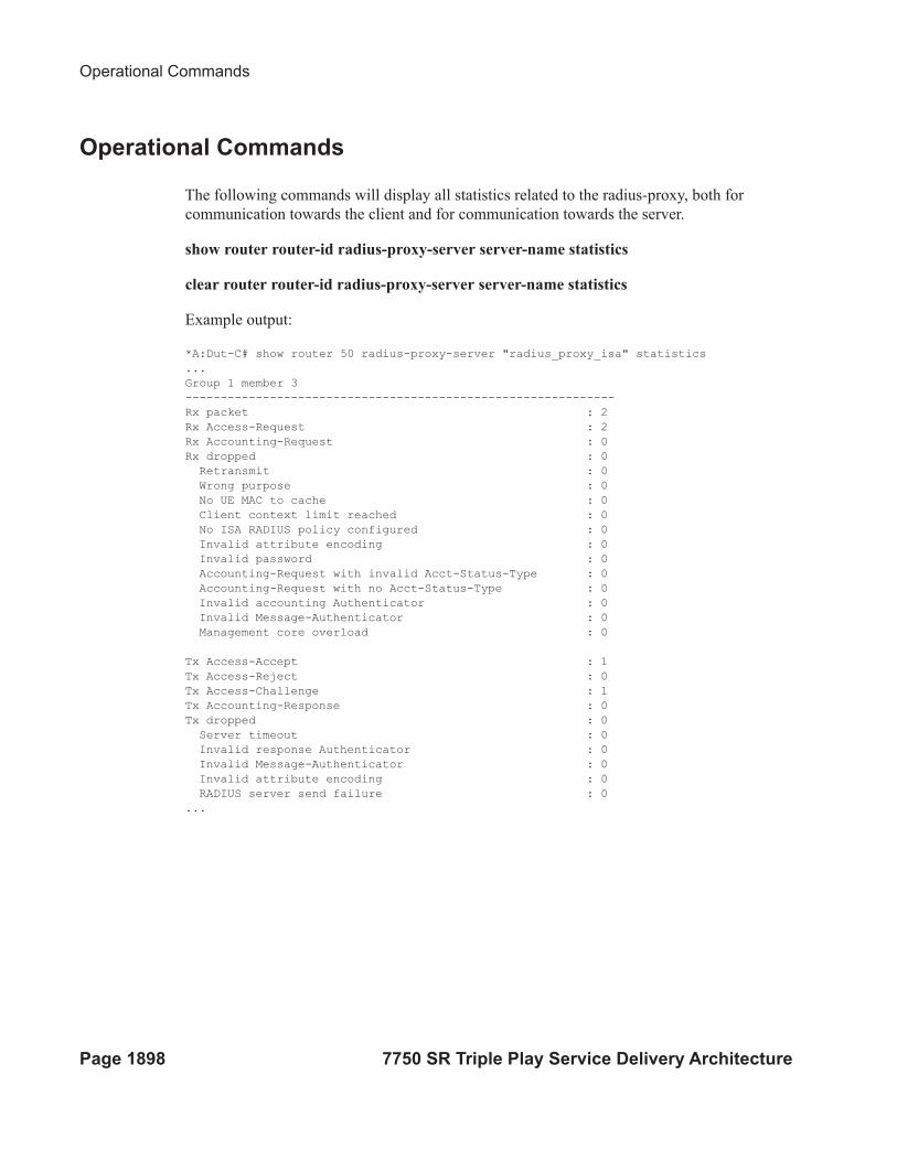
Operational Commands
Page 1898 7750 SR Triple Play Service Delivery Architecture
Operational Commands
The following commands will display all statistics related to the radius-proxy, both for
communication towards the client and for communication towards the server.
show router router-id radius-proxy-server server-name statistics
clear router router-id radius-proxy-server server-name statistics
Example output:
*A:Dut-C# show router 50 radius-proxy-server "radius_proxy_isa" statistics
...
Group 1 member 3
-------------------------------------------------------------
Rx packet : 2
Rx Access-Request : 2
Rx Accounting-Request : 0
Rx dropped : 0
Retransmit : 0
Wrong purpose : 0
No UE MAC to cache : 0
Client context limit reached : 0
No ISA RADIUS policy configured : 0
Invalid attribute encoding : 0
Invalid password : 0
Accounting-Request with invalid Acct-Status-Type : 0
Accounting-Request with no Acct-Status-Type : 0
Invalid accounting Authenticator : 0
Invalid Message-Authenticator : 0
Management core overload : 0
Tx Access-Accept : 1
Tx Access-Reject : 0
Tx Access-Challenge : 1
Tx Accounting-Response : 0
Tx dropped : 0
Server timeout : 0
Invalid response Authenticator : 0
Invalid Message-Authenticator : 0
Invalid attribute encoding : 0
RADIUS server send failure : 0
...
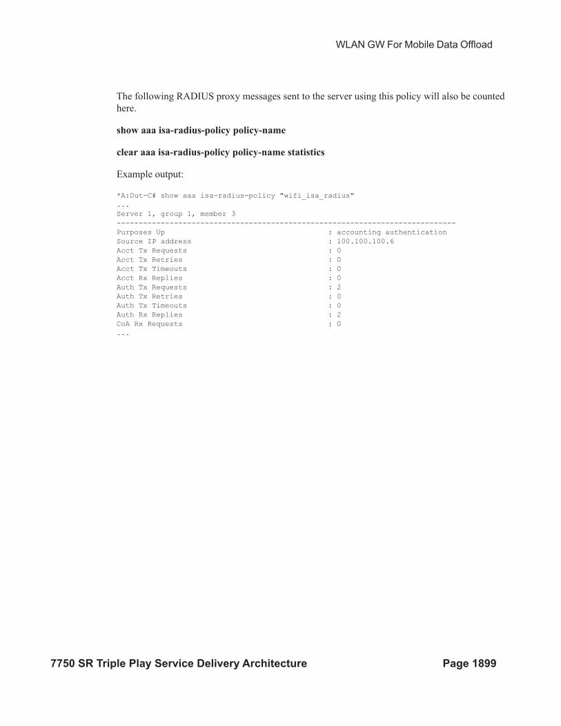
WLAN GW For Mobile Data Offload
7750 SR Triple Play Service Delivery Architecture Page 1899
The following RADIUS proxy messages sent to the server using this policy will also be counted
here.
show aaa isa-radius-policy policy-name
clear aaa isa-radius-policy policy-name statistics
Example output:
*A:Dut-C# show aaa isa-radius-policy "wifi_isa_radius"
...
Server 1, group 1, member 3
-----------------------------------------------------------------------------
Purposes Up : accounting authentication
Source IP address : 100.100.100.6
Acct Tx Requests : 0
Acct Tx Retries : 0
Acct Tx Timeouts : 0
Acct Rx Replies : 0
Auth Tx Requests : 2
Auth Tx Retries : 0
Auth Tx Timeouts : 0
Auth Rx Replies : 2
CoA Rx Requests : 0
...
WLAN-GW 1:1 Active-Backup Redundancy
Page 1900 7750 SR Triple Play Service Delivery Architecture
WLAN-GW 1:1 Active-Backup Redundancy
This feature provides support for 1:1 inter WLAN-GW active-backup redundancy. The failure
detection and switchover mechanism is contained in WLAN-GWs, and there is no dependency on
the AP to detect failure of WLAN-GW and switch traffic to tunnel endpoint on a different WLAN-
GW. There is also no dependency on NAT or a particular flavor of NAT on WLAN-GW. If local
DHCP servers are used for address allocation, then DHCP leases in the server are synchronized to
the backup WLAN-GW via MCS. However, ESM state for the UE is created on the backup
WLAN-GW based on data-triggered authentication after switchover. The granularity of
switchover is subscriber-interface. Both WLAN-GWs are required to be configured with the same
tunnel endpoint address. Also, the subscriber-interfaces on both WLAN-GW must be configured
with the same subnets. Only the WLAN-GW that is deemed as active announces the tunnel
endpoint address in routing towards the APs.
Active-backup decision is based on monitor and export route concept (same as what is used with
NAT redundancy). Monitor and export routes are configured on the subscriber-interface on both
WLAN-GWs. These should be complementary with respect to the ones on the other WLAN-GW.
When WLAN-GW group goes up operationally, check is made in the FIB for presence of monitor
route (which is the route exported by the other WLAN-GW). If it is not found, then the WLAN-
GW assumes active state with respect to ownership of the tunnel end-point address, and the tunnel
end-point address is announced in IGP towards the AP (subject to configured IGP and routing
policy). The active WLAN-GW also announces the aggregate subscriber subnets upstream in
routing. When WLAN-GW group comes up operationally, and detects the monitor route in the
FIB, it assumes standby state with respect to the tunnel endpoint address. It does not announce the
tunnel endpoint or the subscriber subnets in routing.
Each WLAN-GW will need to track the monitor route in the FIB. If the monitor route is no longer
in the FIB, and the WLAN-GW is in standby state, it will transition to active, and announce the
tunnel end-point towards APs, and subscriber subnets upstream. This will draw the traffic from the
AP to the backup WLAN-GW. Redundancy will be non-revertive. The monitor and export routes
are configured on the subscriber-interface.
config>service>ies>sub-if
wlan-gw
redundancy
[no] export <ip-prefix/length>
[no] monitor <ip-prefix/length>
exit
exit
If the number of operationally up WLAN-GW IOMs in wlan-gw group drops below the number of
active IOMs configured, the WLAN-GW group will be brought down (based on the configuration
oper-down-on-group-degrade command under wlan-gw interface), and switchover procedures
for the subscriber-interface are triggered (export route, tunnel endpoint address and subscriber
subnets are withdrawn from routing).
WLAN GW For Mobile Data Offload
7750 SR Triple Play Service Delivery Architecture Page 1901
config>service>vprn>sub-if>grp-if
config>service>ies>sub-if>grp-if
wlan-gw
[no] oper-down-on-group-degrade
The switchover can also be triggered administratively on per subscriber-interface basis using the
tools perform command.
*A:vsim-07-cpm# tools perform wlan-gw redundancy force-switchover service <service-id>
interface <ip-int-name>
DHCP Server Redundancy
1:1 redundancy provided with this feature only handles complete failure of WLAN-GW (either
due to chassis reboot or due to number of operational WLAN-GW IOMs in WLAN-GW group
falling below the number of active WLAN-GW IOMs, which will operationally bring down the
WLAN-GW group, and trigger switchover). For any partial failures (port, MDA or IOM failure),
it is assumed there is network level redundancy, such that the soft-GRE tunnel will be re-routed to
the primary WLAN-GW. This ensures there is only one active WLAN-GW owning the subnets
defined on the two WLAN-GWs (that is, allows local/local subnets). The DHCP server(s) state
will be synchronized between the two WLAN-GWs using MCS.
Supported access includes:
• DHCPv4 Relay to external server.
• DHCPv4 Relay to local server.
→ Pool name could be returned by AAA (framed-pool) in access-accept.
→ Pool name could come from LUDB (as relay we would set use-pool-from-client).
LUDB could be specified under group-interface or under DHCP server. LUDB or
AAA returned pool allows support for per SSID pool selection. SSID is contained in
circuit-id.
→ Local pool selection based on giaddr.
• DHCPv4 proxy (IP@ from AAA or IP@ from PGW/GGSN).
Unnumbered case should work both in relay and proxy scenarios. IPv6 is not supported in this
release (as we don’t support data-triggered auth and subscriber creation for IPv6). Therefore,
DHCPv6 server synchronization is not applicable. Also, IPv4 address from LUDB is not
supported in this release (as data-triggered authentication against LUDB is not supported).
Subscriber Creation after Switchover
Page 1902 7750 SR Triple Play Service Delivery Architecture
Subscriber Creation after Switchover
When standby WLAN-GW transitions to active state, and receives data on the anchor ISA there
will not be any UE state on the anchor ISA. Data-triggered authentication Data Triggered
Subscriber Creation on page 1877 will be used to create the subscriber. In order to infer how the
UE originally obtained the IP@ (DHCP relay versus proxy, such as AAA or GTP), the following
holds:
1. If any GTP related parameters are returned in access-accept, then it is assumed the IP@
comes from GGSN/PGW, and the origin for the IP@ is assumed to be “GTP”.
2. If no GTP parameter is returned, and access-accept contains framed-IP, then proxy case will
be assumed (that is, the origin as AAA).
3. If no GTP parameter or framed-IP is returned, then DHCP relay is assumed. The remaining
lease time will be set to initial lease-time (if it was originally provided from AAA on primary
WLAN-GW, it could be provided in access-accept for data-triggered auth on backup WLAN-
GW). If AAA does not provide it, then it will be initialized to default value of 7 days.
If authentication indicates GTP for the subscriber, then create-session-request will be signaled
with Handover indication. Data-triggered subscriber creation based on IPv6 packet is not
supported in R12. However, for dual-sack subscriber over soft-GRE, if AAA returns the SLAAC
prefix in access-accept (in response to IPv4 data-triggered auth), and linking is configured, RA
message will be sent (unicast to client’s MAC@), and a SLAAC host is created.
WLAN GW For Mobile Data Offload
7750 SR Triple Play Service Delivery Architecture Page 1903
WLAN-GW Triggered Stateless Redundancy (N:1)
Existing stateless redundancy, described in Data Triggered Subscriber Creation on page 1877, is
enhanced to support WLAN-GW based failure detection and switchover based on monitor and
export route mechanism described above. The AP is not required to be configured with different
tunnel endpoint addresses for active and standby WLAN-GWs. Single tunnel endpoint address is
configured on the APs. The tunnel endpoint address is only announced in routing by the primary
WLAN-GW as described in the section above. This form of redundancy as described in Data
Triggered Subscriber Creation on page 1877, required L2-aware NAT. After failure, the subscriber
on the standby WLAN-GW that transitions to primary is based on data-triggered authentication.
This is supported for both ESM and DSM.
AP Triggered Stateless WLAN-GW Redundancy (N:1)
Page 1904 7750 SR Triple Play Service Delivery Architecture
AP Triggered Stateless WLAN-GW Redundancy (N:1)
Existing AP controlled redundancy, described in Data Triggered Subscriber Creation on page
1877, is enhanced to trigger switchover on primary WLAN-GW if the number of WLAN-GW
IOMs in the WLAN-GW group fall below number of active WLAN-GW IOMs. Based on a
configuration configure>service>vprn|ies svc>subscriber-interface sub-if>group-interface
grp-it>wlan-gw command, the WLAN-GW group is operationally brought down if a WLAN-GW
IOM fails and the number of WLAN-GW IOMs fall below number of active WLAN-GW IOMs
configured for the WLAN-GW group. This results in loss of route to the tunnel endpoint from the
active WLAN-GW. The AP will detect this as WLAN-GW failure, and start tunneling the data to a
configured backup WLAN-GW, where the subscriber will be created based on data-triggered
authentication.This is supported for both ESM and DSM.
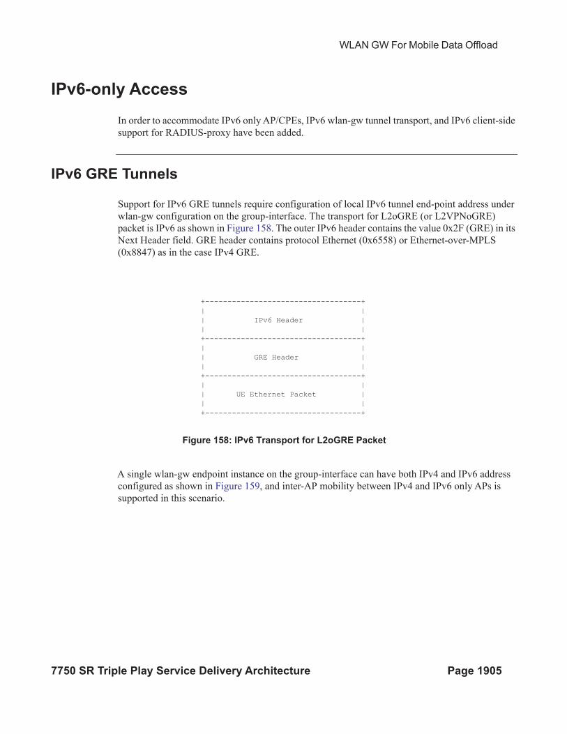
WLAN GW For Mobile Data Offload
7750 SR Triple Play Service Delivery Architecture Page 1905
IPv6-only Access
In order to accommodate IPv6 only AP/CPEs, IPv6 wlan-gw tunnel transport, and IPv6 client-side
support for RADIUS-proxy have been added.
IPv6 GRE Tunnels
Support for IPv6 GRE tunnels require configuration of local IPv6 tunnel end-point address under
wlan-gw configuration on the group-interface. The transport for L2oGRE (or L2VPNoGRE)
packet is IPv6 as shown in Figure 158. The outer IPv6 header contains the value 0x2F (GRE) in its
Next Header field. GRE header contains protocol Ethernet (0x6558) or Ethernet-over-MPLS
(0x8847) as in the case IPv4 GRE.
Figure 158: IPv6 Transport for L2oGRE Packet
A single wlan-gw endpoint instance on the group-interface can have both IPv4 and IPv6 address
configured as shown in Figure 159, and inter-AP mobility between IPv4 and IPv6 only APs is
supported in this scenario.
+-----------------------------------+
| |
| IPv6 Header |
| |
+-----------------------------------+
| |
| GRE Header |
| |
+-----------------------------------+
| |
| UE Ethernet Packet |
| |
+-----------------------------------+
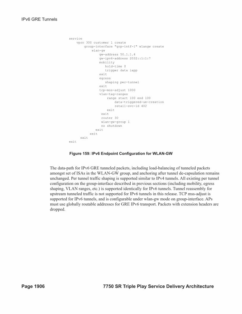
IPv6 GRE Tunnels
Page 1906 7750 SR Triple Play Service Delivery Architecture
Figure 159: IPv6 Endpoint Configuration for WLAN-GW
The data-path for IPv6 GRE tunneled packets, including load-balancing of tunneled packets
amongst set of ISAs in the WLAN-GW group, and anchoring after tunnel de-capsulation remains
unchanged. Per tunnel traffic shaping is supported similar to IPv4 tunnels. All existing per tunnel
configuration on the group-interface described in previous sections (including mobility, egress
shaping, VLAN ranges, etc.) is supported identically for IPv6 tunnels. Tunnel reassembly for
upstream tunneled traffic is not supported for IPv6 tunnels in this release. TCP mss-adjust is
supported for IPv6 tunnels, and is configurable under wlan-gw mode on group-interface. APs
must use globally routable addresses for GRE IPv6 transport. Packets with extension headers are
dropped.
service
vprn 300 customer 1 create
group-interface "grp-intf-1" wlangw create
wlan-gw
gw-address 50.1.1.4
gw-ipv6-address 2032::1:1:7
mobility
hold-time 0
trigger data iapp
exit
egress
shaping per-tunnel
exit
tcp-mss-adjust 1000
vlan-tag-ranges
range start 100 end 100
data-triggered-ue-creation
retail-svc-id 402
exit
exit
router 30
wlan-gw-group 1
no shutdown
exit
exit
exit
exit
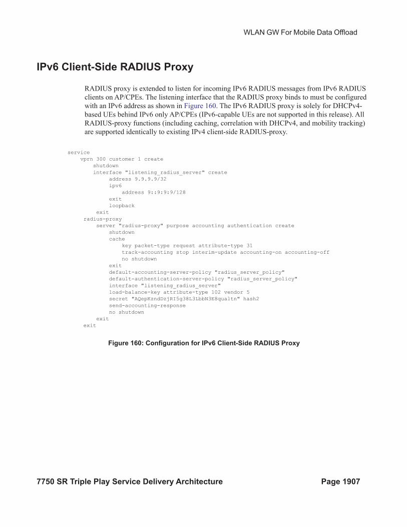
WLAN GW For Mobile Data Offload
7750 SR Triple Play Service Delivery Architecture Page 1907
IPv6 Client-Side RADIUS Proxy
RADIUS proxy is extended to listen for incoming IPv6 RADIUS messages from IPv6 RADIUS
clients on AP/CPEs. The listening interface that the RADIUS proxy binds to must be configured
with an IPv6 address as shown in Figure 160. The IPv6 RADIUS proxy is solely for DHCPv4-
based UEs behind IPv6 only AP/CPEs (IPv6-capable UEs are not supported in this release). All
RADIUS-proxy functions (including caching, correlation with DHCPv4, and mobility tracking)
are supported identically to existing IPv4 client-side RADIUS-proxy.
Figure 160: Configuration for IPv6 Client-Side RADIUS Proxy
service
vprn 300 customer 1 create
shutdown
interface "listening_radius_server" create
address 9.9.9.9/32
ipv6
address 9::9:9:9/128
exit
loopback
exit
radius-proxy
server "radius-proxy" purpose accounting authentication create
shutdown
cache
key packet-type request attribute-type 31
track-accounting stop interim-update accounting-on accounting-off
no shutdown
exit
default-accounting-server-policy "radius_server_policy"
default-authentication-server-policy "radius_server_policy"
interface "listening_radius_server"
load-balance-key attribute-type 102 vendor 5
secret "AQepKzndDzjRI5g38L3LbbN3E8qualtn" hash2
send-accounting-response
no shutdown
exit
exit
Dual-Stack UEs over WLAN-GW
Page 1908 7750 SR Triple Play Service Delivery Architecture
Dual-Stack UEs over WLAN-GW
This feature adds support for dual-stack UEs over wlan-gw. Each dual-stack UE appears to
WLAN-GW as a bridged client. Dual-stack UE support includes both SLAAC and DHCPv6, with
and without linking with DHCPv4. Handling of DHCPv6, RS/RA, and NS/NA messages over
wlan-gw has been added. WLAN-GW can assign /128 GUA to the UE via DHCPv6 and/or assign
a /64 prefix in SLAAC to each UE. Each UE can be handed via DHCPv6, a /128 IA_NA from a
unique /64 prefix, with the “on-link” flag is off in the RA message. This is because the public
WIFI users are distinct subscribers, and the communication must always be via WLAN-GW. The
CPE MUST prevent local-switching on the WIFI link even if the /64 prefix is signaled as “on-
link” or if the UEs are handed out /128 from the same /64 prefix.
Existing ESMv6 support on normal group-interface is applicable to wlan-gw group-interface, and
is already documented in general ESMv6 sections in this guide. There are a few exceptions that
are mentioned in sections below.
SLAAC Prefix Assignment
SLAAC prefix assignment to the UE can be from local prefix pool, where pool name can come
from RADIUS in Alc-SLAAC-IPv6-Pool VSA or from LUDB (see general section on ESMv6
SLAAC pool assignment). Alternatively, the SLAAC prefix can be provided from RADIUS (in
standard Framed-IPv6-Prefix attribute) or from LUDB. SLAAC with stateless DHCPv6 (DHCPv6
information-request) is supported. DNS can be sent in RA messages (per RFC 6106). RS
authentication (based on MAC address) can be configured (as described in general ESMv6 section
on “SLAAC only ESM hosts”). SLAAC host is created on successful RS authentication. For
successfully authenticated SLAAC host, an RA is sent in response to every received RS message
(subject to a configured min-auth-interval). RA messages are sent to unicast MAC address of the
UE.
SLAAC host creation can be linked to DHCPv4 by configuring ipoe-linking under group-
interface. With ipoe-linking enabled, any received RS messages are dropped till DHCPv4
successfully authenticates and ESMv4 host is created. If gratuitous-rtr-adv is configured under
ipoe-linking context then an RA is sent when ESMv4 host is created. If available, the SLAAC-
prefix is included in the RA message. shared-circuit-id command under wlan-gw is not supported
on wlan-gw interfaces. The O-Bit (other-stateful-configuration) is configurable on the group-
interface.
DHCPv6 IA_NA Assignment
If UE requests DHCPv6 IA_NA, a /128 address can be provided from a unique /64 prefix per UE
from a local-pool. The pool name can be provided from LUDB or from RADIUS (in Framed-
WLAN GW For Mobile Data Offload
7750 SR Triple Play Service Delivery Architecture Page 1909
IPv6-Pool attribute). The address could also be provided via LUDB or RADIUS (in Alc-IPv6-
Address VSA). DHCPv6 can also be linked with DHCPv4 by enabling ipoe-linking command.
The M-bit in RA message is configurable. DHCPv6 IA_NA is allowed if it is received after a
SLAAC host exists, if allow-multiple-wan-addresses is enabled under group-interface ipv6
configuration. In previous releases, this is precluded. This however consumes two hosts (one each
for IA_NA and SLAAC) per UE. Based on a configuration command override-slaac, SLAAC
host can be deleted if DHCPv6 IA_NA host is successfully created. Prefix-delegation is not
supported with DHCPv6 on wlan-gw interfaces.
Migrant User Support
Migrant user support is only applicable to IPv4. However, if linking is configured for SLAAC or
DHCPv6 with DHCPv4 then RS and DHCPv6 messages are dropped till IPv4 ESM host exists
(that is, the UE is out of migrant state). Once the IPv6 ESM host exists, that is, UE is out of
migrant state, RA is sent to the UE (unicast MAC), and subsequent RS or DHCPv6 messages can
result in creation of IPv6 ESM host. Therefore, with migrant UEs, linking should be enabled.
SLA-profile instance accounting (with interim-updates), and per-host accounting (w/ interim-
updates) are supported.
Accounting
Per SLA-profile instance accounting (with interim-updates) and per SLA-profile instance
accounting (with interim-updates) with host accounting enabled is supported. The interim-updates
are scheduled updates, and carry IPv4 address and IPv6 address or prefix are assigned to the UE.
A sample sequence with per SLA-profile instance accounting (with interim-updates) is shown
below:
0. IPv4oE host created based on DHCPv4.
1. Acct-start generated (contains framed-ip-address).
2. SLAAC host comes up.
3. Next scheduled interim-update (contains framed-ip-address and framed-IPv6-Prefix,
that is, SLAAC-prefix).
4. DHCPv6 IA_NA gets assigned and corresponding host is created.
5. Next Scheduled interim-update (contains framed-ip-address, framed-IPv6-Prefix and
Alc-Ipv6-Address).
6. SLAAC host times out.
7. Next Scheduled interim-update (contains only Alc-IPv6-Address and will NOT contain
framed-IPv6-Prefix).
Dual-Stack UEs over WLAN-GW
Page 1910 7750 SR Triple Play Service Delivery Architecture
8. DHCPv6 IA_NA lease times out.
9. Next Scheduled interim-update (contains only framed-ip-address).
A sample sequence with per SLA-profile instance accounting (with interim-updates) with host
accounting enabled is shown below:
0. IPv4oE host created based on DHCPv4.
1. Acct-start for sla-profile instance generated (contains framed-ip-address).
2. Acct-start for DHCPv4 host will be generated (contains framed-ip-address).
3. SLAAC host comes up.
4. Acct-start for SLAAC host will be generated (this should contain framed-IPv6-Prefix,
that is, SLAAC-prefix)
5. Next scheduled interim-update for sla-profile instance accounting (contains framed-ip-
address and framed-IPv6-Prefix, that is, SLAAC-prefix).
6. DHCPv6 IA_NA gets assigned and corresponding host is created.
7. Acct-start for DHCPv6 IA_NA host will be generated (contains Alc-Ipv6-Address).
8. Next Scheduled interim-update (contains framed-ip-address, framed-IPv6-Prefix and
Alc-Ipv6-Address).
9. SLAAC host times out.
10. Acct-stop (SLACC-host-acct-session-id) will be generated.
11. Next Scheduled interim-update for sla-profile instance accounting (contains only Alc-
IPv6-Address).
12. DHCPv6 IA_NA lease times out.
13. Acct-stop (DHCPv6-IA_NA-host-acct-session-id) will be generated.
14. Next Scheduled interim-update for sla-profile instance accounting (contains framed-
ip-address).
15. DHCPv4 lease times out.
16. Acct-stop (DHCPv4-host-acct-session-id) will be generated.
17. Acct-stop for sla-profile instance accounting will be generated.
WLAN GW For Mobile Data Offload
7750 SR Triple Play Service Delivery Architecture Page 1911
Layer 2 Wholesale
This feature adds support for mapping a UE to a VPLS instance based on configuration. The
mapping is explicitly created by assigning a Layer 2 service instance (limited to VPLS only in R.
13) to an SSID that the UE is connected to. The SSID is represented by the .1q tag in the received
Layer 2 frames from the UE. A VPLS instance is configured per vlan-range on wlan-gw group-
interface (as shown in Figure 142 on page 1824). This feature therefore enables Layer 2
wholesale, where traffic form all UEs on a particular SSID is transparently forwarded into the
corresponding VPLS instance associated with the retail ISP. UE authentication, address
assignment, Layer 3 classification and QOS are managed by the retail provider terminating the
subscriber. There is no local-switching on the WLAN-GW providing the wholesale service. When
a VPLS instance is configured under a VLAN-range, an internal SAP is implicitly created in the
VPLS instance between each ISA and corresponding carrier IOM in the WLAN-GW group. The
internal SAP is associated with an implicitly created SHG to constrain broadcast and multicast
traffic received from UEs, such that it is not forwarded back on the SAP. Layer 2 wholesale and
Layer 3 termination are possible simultaneously on same wlan-gw interface, since Layer 2
wholesale or Layer 3 termination is a per SSID decision. UE state on the ISA is removed when the
UE MAC in the VPLS instance ages out based on local-age configured under VPLS service.
A vpls-sap-template (described in the SR OS Services Guide) can be defined under
service>template and associated with the VPLS service for Layer 2 wholesale via
config>service>vpls>wlan-gw>sap-template command. Ingress/egress filter and QoS specified
in the vpls-sap-template for the VPLS service is applied to the implicitly created internal SAP
(between ISA and carrier IOM) in the VPLS service.
*A:vsim>config>service>vprn# info
----------------------------------------------
subscriber-interface "s1" create
group-interface "g1" wlangw create
wlan-gw
vlan-tag-ranges
range start 100 end 100
l2-service 600
no shutdown
exit
exit
exit
exit
----------------------------------------------
*A:vsim>config>service>vpls# info
---------------------------------------------
wlan-gw
shutdown
sap-template "foo"
exit
----------------------------------------------
VLAN to WLAN-GW IOM/IMM Steering via Internal Epipe
Page 1912 7750 SR Triple Play Service Delivery Architecture
VLAN to WLAN-GW IOM/IMM Steering via Internal Epipe
This feature provides the steering of traffic received on an access VLAN or spoke SDP from a WIFI AP/AC to a
WLAN-GW IOM/IMM via an internal Epipe. The benefit of this internal steering is that all existing features available
with native soft GRE tunnels on WLAN-GW IOM/IMM are now available to pure Layer 2 access via VLANs or spoke
SDPs. The access SAP can be null, .1q, or q-in-q. Access SAPs aggregating WIFI APs or ACs can and be configured in
the configure>service>ies>subscriber-interface>group-interface>wlan-gw>l2-access-points>l2-ap or
configure>service>vprn>subscriber-interface>group-interface>wlan-gw>l2-access-points>l2-ap context
The aggregation network can insert up to two AP identifying VLAN tags, and the AP can insert a .1q tag (typically for
identifying the SSID). The number of AP identifying tags sent on the internal epipe depends on the encapsulation on the
access SAP. For example, if an aggregation network inserts two AP identifying tags, and an access SAP is configured
with null encaps, then the traffic sent on the internal Epipe will carry two AP identifying tags. The number of AP
identifying tags in the frame forwarded over the internal Epipe must be configured via the l2-ap-encap-type command.
configure service (vprn|ies) <svc-id> subscriber-interface <sub-itf> group-interface <grp-
itf> wlan-gw
l2-access-points
[no] l2-ap <sap-id> [create]
[no] encap-type {default|null|dot1q|qinq}
[no] epipe-sap-template <name>
[no] shutdown
exit
exit
[no] l2-ap-encap-type {null|dot1q|qinq}
exit
The traffic on an internal Epipe is load-balanced among ISAs in the WLAN-GW group. The load balancing uses a hash
based on AP identifying tags that remain on the frame after being received on the access SAP (based on the SAP
encapsulation). This ensures all traffic from a particular AP is Epiped to the same ISA. Ingress and egress QoS and
filters can be defined in an epipe-sap-template as displayed in the configuration shown below, and associated with the
access sap or spoke SDP. IP filters and DSCP remarking are not supported if more than two tags are present in the frame
ingressing the SAP. Also, downstream filters and DSCP remarking is not applied if a retail tag is present. Both Layer 3
ESM and DSM as well as Layer 2 wholesale are supported for steered traffic.
configure service template epipe-sap-template <name> [create]
egress
[no] filter
[no] ip <filter-id>
[no] ipv6 <filter-id>
[no] mac <filter-id>
exit
[no] qos <policy-id>
exit
ingress
[no] filter
[no] ip <filter-id>
[no] ipv6 <filter-id>
[no] mac <filter-id>
exit
[no] qos <policy-id> {shared-queuing|multipoint-shared}
exit
exit
WLAN GW For Mobile Data Offload
7750 SR Triple Play Service Delivery Architecture Page 1913
Currently, mobility from an AP that is reached over a VLAN or spoke SDP to an AP that is reached over a soft GRE or
soft L2TPv3 tunnels are not supported. Each internal Epipe takes away two SAPs on each WLAN-GW IOM (one per
ISA) in WLAN-GW group. With 64K SAPs per IOM, the maximum number of internal Epipes supported per chassis is
32K.
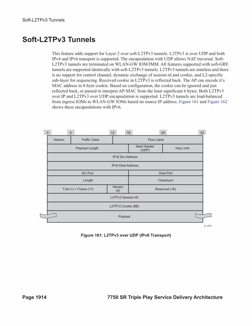
Soft-L2TPv3 Tunnels
Page 1914 7750 SR Triple Play Service Delivery Architecture
Soft-L2TPv3 Tunnels
This feature adds support for Layer 2 over soft-L2TPv3 tunnels. L2TPv3 is over UDP and both
IPv4 and IPv6 transport is supported. The encapsulation with UDP allows NAT traversal. Soft-
L2TPv3 tunnels are terminated on WLAN-GW IOM/IMM. All features supported with soft-GRE
tunnels are supported identically with soft-L2TPv3 tunnels. L2TPv3 tunnels are stateless and there
is no support for control channel, dynamic exchange of session-id and cookie, and L2-specific
sub-layer for sequencing. Received cookie in L2TPv3 is reflected back. The AP can encode it’s
MAC address in 8-byte cookie. Based on configuration, the cookie can be ignored and just
reflected back, or parsed to interpret AP-MAC from the least significant 6 bytes. Both L2TPv3
over IP and L2TPv3 over UDP encapsulation is supported. L2TPv3 tunnels are load-balanced
from ingress IOMs to WLAN-GW IOMs based on source IP address. Figure 161 and Figure 162
shows these encapsulations with IPv6.
Figure 161: L2TPv3 over UDP (IPv6 Transport)
al_0643
0 4 12 16
Payload
L2TPv3 Cookie (8B)
L2TPv3 Session-ID
Reserved (16)Version
(4)T-bit (1) + Future (11)
Length Checksum
Src Port Dest Port
IPv6 Dest Address
IPv6 Src Address
Traffic ClassVersion Flow Label
Next Header(UDP)
Payload Length Hop Limit
24 32
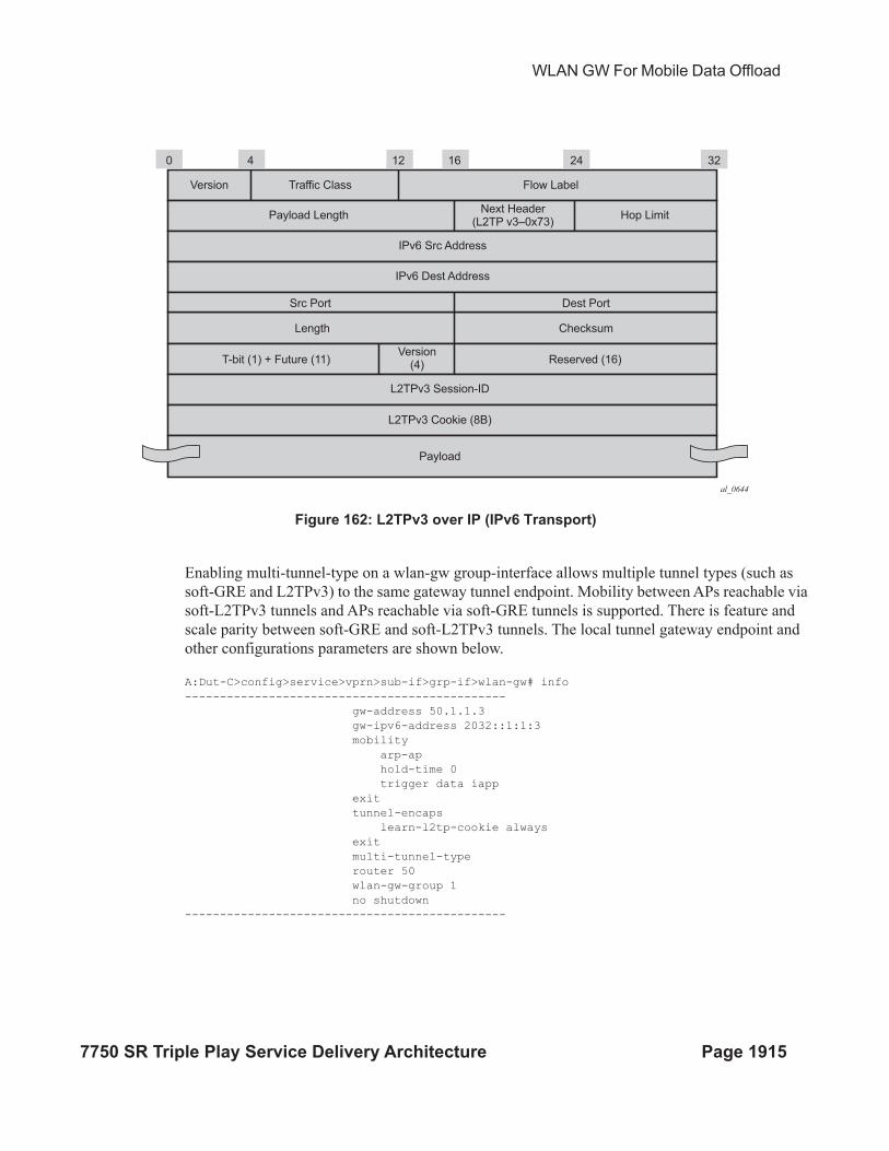
WLAN GW For Mobile Data Offload
7750 SR Triple Play Service Delivery Architecture Page 1915
Figure 162: L2TPv3 over IP (IPv6 Transport)
Enabling multi-tunnel-type on a wlan-gw group-interface allows multiple tunnel types (such as
soft-GRE and L2TPv3) to the same gateway tunnel endpoint. Mobility between APs reachable via
soft-L2TPv3 tunnels and APs reachable via soft-GRE tunnels is supported. There is feature and
scale parity between soft-GRE and soft-L2TPv3 tunnels. The local tunnel gateway endpoint and
other configurations parameters are shown below.
A:Dut-C>config>service>vprn>sub-if>grp-if>wlan-gw# info
----------------------------------------------
gw-address 50.1.1.3
gw-ipv6-address 2032::1:1:3
mobility
arp-ap
hold-time 0
trigger data iapp
exit
tunnel-encaps
learn-l2tp-cookie always
exit
multi-tunnel-type
router 50
wlan-gw-group 1
no shutdown
----------------------------------------------
al_0644
0 4 12 16
Payload
L2TPv3 Cookie (8B)
L2TPv3 Session-ID
Reserved (16)Version
(4)T-bit (1) + Future (11)
Length Checksum
Src Port Dest Port
IPv6 Dest Address
IPv6 Src Address
Traffic ClassVersion Flow Label
Next Header(L2TP v3–0x73)
Payload Length Hop Limit
24 32
Soft-L2TPv3 Tunnels
Page 1916 7750 SR Triple Play Service Delivery Architecture