Embed Size (px)
Citation preview

.,
,., .. NATIONU ADVISORY COMMI’ITEE FOR AERONAUTICS
Wi!!lmmm IUWORTORIGINALLY ISSUED
June lS#@ asRestrictedBulletln
WY Memmlel AeraluutloalIaol’atoz7 “L=6W FieM, Pa.
WASHINGTON
NACA WARTIMZ REPORTSarereprlntiofpapersoriginallylesuedtoproviderapiddtstrlbutlonofadvanceresearchresultstoanauthorizedgrouprequiringthemforthewareffort.Theywerepre-viouslyheldunderasecwltystatusbutarsnowunclassified.Someoftheserqxn’tewere nottech-nicallyedited.Allhavebeenreproducedwithoutchangeinordertoexpeditegeneraldistribution.
L -294

!?3117601354 2S01 r
3
. .XAl!IOMAZ ADVIS~t 00MHITTEH FOE ASROMAUTIQS
,.. . RES~RICTED BULIJB!PIlf... ,- %”.\-...l, ... ........ ...-. ......... ... ,..
.:. .b STUDY O; TEE !EItMIT”qSS MD rliUSHIE8S OY HA6HIB3-
.COUETBllSUllK RIVBTS1l’OB AIROSAE9. “
19 &Nna S. Luadqulst and hobcrt Gottlteb
t-’.. ..- ,. ‘ Stiu.m .-.. ...”
.
!Cha”roaultm of an ~nrestigntlon ui)dmtakon to dotor-mipe p.ooslble Smpsovemento Zp the tightness and the flu8h-neos of maoh~ne~couatorsunk *lTets ● ro presontodi spao-imene used In this btudy were eimple lap Joltitemade by6$ffarant rlvetlng m~thod8. .
The result? ”revea~.d the”neceoalty of ha.?ingt“h.height of the rivet heads greater than the depth of theeouptersunk holds. if tight rlreted ~olnts wsre to be ob-tained. Machihe_aPuatereu.nk rivets thu”s instello+ pso-truded above the ●kln @urfaoe after the .rivete were driven.!Choprotruding portions of the rivet “heads had to be re-mosed In order to obtain flmeh rl.ydta. If ordinary round-head.riyeto were lntaqr~ed from the .oppoeite elde OS the,~oint anclthe countersunk “heads”formed in the drlvin~ OYthe rivets filled the countersunk holes completely, still.tlghter riveted JQ$p$e wsrs ,Pp.talpedm... .
. .““i31TRODUCTiOlf‘ “ ““ “.” ‘“
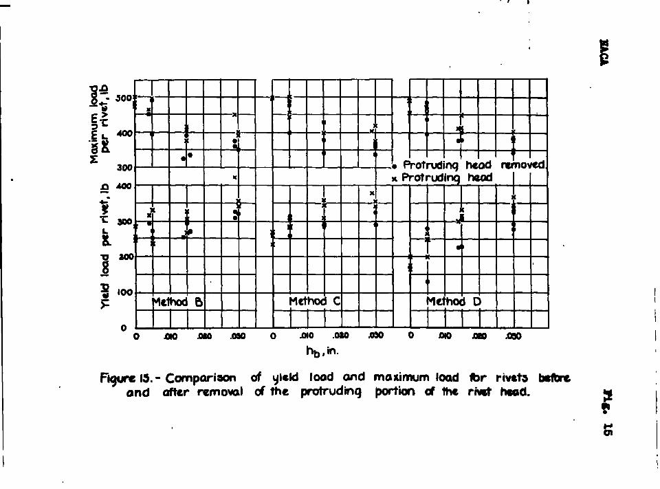
Plush slvets in the’ okin bf airmpla&ob”hre’not alwaystight and perfeetly faired with the whg or fuselagp our-taee, (Ss0 flgt. 15)- Whsn the rtwtm ar.e.not..$lglit,ex-oeesiv~ permanent d~tplaceme.pt of the atta.ehet parth maYrondos the joints qflt.fofi the.mopviab ro.qnlrod after ●
small peroantage of the maximum load has beon:applSed9When the rlveta ase not pepfect~y faired, 8 smooth surmfaeo from the aerodynamic ●tandp~iut to not aohieved.
1
. .
a
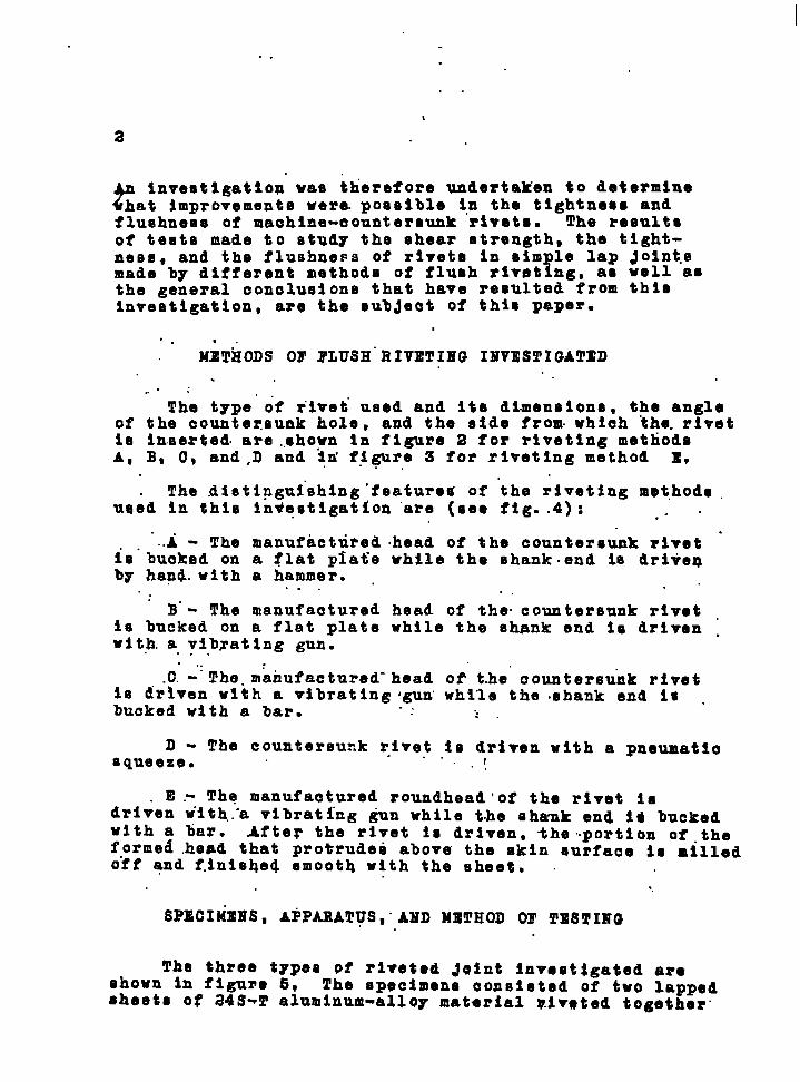
?Investlgatlon wata therefore undertaken to determine
hat improvements were.potaeible in the tlghtnea~ andflushnees of machine-countersunk rivets. The resultsof teeta made to study the tahear strength, the tight-ness~ and the flushness of rivets in sim lo lap Joints
i’made by different methods of flush riveb ng, aa well asthe general conolusionta that have resulted from thimInvestigation, are the eub~eet of this paper.
. . ,.
METiiODS 03’YLUSH”RIVETIIWG II?VESTIC+ATED.
..,:
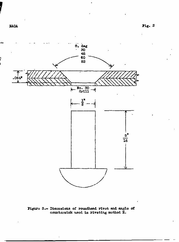
The type”of rivet used and its dimensions, the angleof the countersunk hole, and the side from- whteh the.rivetie 5n8erted.are..ehown tn figure 8 for riveting metliodeA, B. 0, and,D and in’f~gure 3 for riveting method E.. .
The .dlstlpgui”ehlng’feafureu of ‘the riveting mt.hodc .used in this In@osttgation “are (see fig. .4): .“
..A - The manufactured head of the countersunk r5vet .~s”buckad on a flat p~atiewhile the Bhank.end Im dri+e~by hap% with a hammer. ,
.. . . ...B.- The manufactured head of the”countersunk rivet ,
is bucked on a flat plate while the shank end is driven ,with.a vibrating gun... .
c“-“:The.m&ufactured-head of the”countersunk rivetIS dr_l&enwith a vibrating igun”while the shank end IS -bucked with a bar. .. .:
D- The countereuzk rzlvet to driven with a pneumatloSqueeze.
. . .1
.E.- Thq manufactured roundhead ’of the rivet isdriven tilth..-avibrating @n while the eha-nkend id buckedwith a bar. After the rivet 18 driven, the”.portion of.theformed head that protruded abova the skin eurfaoe is milledoff and f.inisqed smooth with the sheet, .
..
SPECIMEBS, APPAEATUS,”AIID METHOD Or TESTIHG
The three t~pee of riveted ~alnt inveat~gated areshown In figure S* The apectmena consisted of two lappedsheets of 24S-!Caluminum-alloy material r.i~ated together”
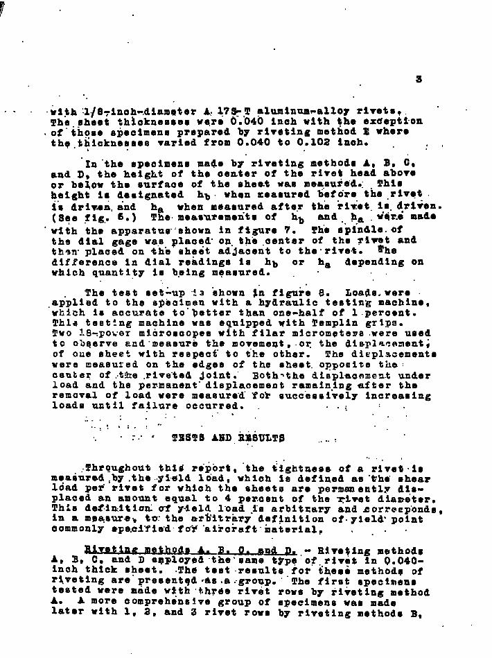
. . . .&t$h :l~8Y3noh-,dSam@ter A.47*,T aluminum-alloy rivete~ . “l!ho.sheet th~oknesses wqro 0.040 inch with ~he exaapttonof those s~ecimens prepared by rl~eting method E wheretho.thicknesses varied from 0.040 to O.1O2 inch. . ~ ,,
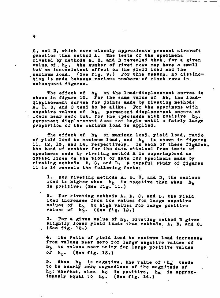
“In”the speeimens made by riveting method- A~ B~ CDand D. the height of the oenter of the rivet head aboveor below the surfaoe of the sheet was mea.su~e”di ghssheight i? designated hb. when measured befcirethe .riv.t .&s driv.ea,and ha when measured after tho ?Iw”et.1s.drl+en.(See fig> 60) The.meastzremen-tsof hb and. ~-a.v’d%emed.
.
‘with the apparatue’shown in fSgU?O 7- l!hoepi_ndle.ofths dial gage was placed. on.the .aenter of the rlvm~oandth~n plaaed on +ho sheet ad~aeent to the”rive.t-difference in dial readings 1s hb or ha depending onwhich quantity ie being measured. . . . .
The test set%p 43 ehown In figure 8. Loads.were ..ap”pliedto the spoainienwith a hydraulic testing machine,which is accurate to”~etter than one-half of l.percsnt.Thla teet:ng machine was equipped with Templin grips.Two z.8-Fewermlarosaopes with filar micrometers were usedto obeerve end.measurb the moyememt, or the dlsplaeenont;of oue sheet with respeef to the other. The displacementswere rzeasured on the edges of the sheet.opposite the :osuteq of ,.the.rive”tedJoint.” Both~the dieplaenmen.t underload and the permanent” displacement ramain.ingaf~er theremoval of load were measure”d”YoZ succ”eseively Increasingloads until failure occurred. . .~
.“$. . . . .......:: . :. : “““, :.”’ TESTS AliDjirn8ULTS ....,
.,..,
.Throughout thld report, “the tightness of a rivet-ismoaeursd ,by.the..yi.0ldload, whioh ie deftaed ae the” ehearload pef rivet for which the sheets are permanently disp-laced an amount equal to 4 per.sent of the “~ivet dlanteter.ThAa da$.initloti uf y-ield l“oad-i_B arbit~ary and &orreep”onds,In a UIpaeUret tu:the erb’itrar~ de$$nitlon of.yield”pointoommonly sFe.cl”fle”d”fo”F.aikcraft”rnater5alP . . . .
da A. p~end p% - Rire$lmg methodsA, B, C, and D eqp;oyed.the’same t$pq”of.rlve~ in Q.04(3-inoh thick sheet. .Th@ test results for theoe methods ofrlvetlng are presentqd 4s .a~group, ““The first specimenstested were made wtth “thrde rivet rows by iiveting methodA. A ❑ ore comprehensive group of specimens was madelater with 1, 2, and 3 rivet rows b~ riveting methods B.
4
,C, and D, which more cloeely approximate present airoraftpractice than method A. The tests of the speoimeneriveted by methods B, C, and D revealed that, for a given
# value.of . hb s the number of rivet rows may have a @mallbut”an inconslutent effect on the yteld load and the
.“maximumload. (See fig. 9.) ~or this reason, no d$atinc-tlon is made between various numbers- of rivet rowe insubsequent ftgures.
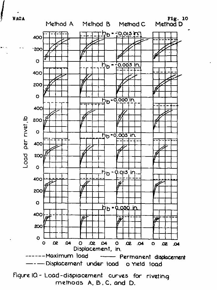
The effect of - hb on the load-displacement curvee lashown in figure 10. Yor the same value of hb, the load-dioplaoement curves for ~ointtamade by riveting methodsA, B, C, and D tend to be alike. ~or the epeclmens withnegative valves of hb , permanent displacement oocurs at
“ loads near zero but, for the specimens with positive hb ,permanent displacement does not begin until a fairly largeproportion of the maximum load is applied.
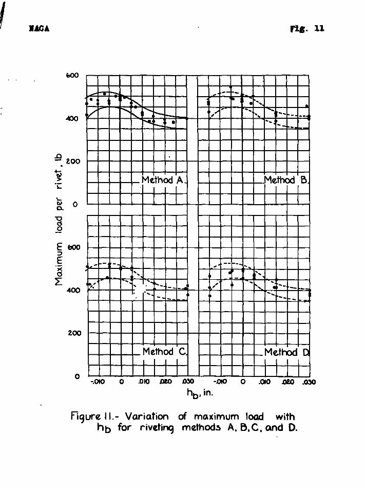
The effect of hb on maximum load, yield load, ratioof yield load to maximum load, and ha Is shown in figures11, 12, 13, and 14, respectively, In each of these’figures,the band of scatter for the data obtained from tetsts ofspecimens made by riveting method A is superimposed asdotted lines on the plots of data for specimens made byriveting methods B, C, and D. A careful study of ~lgures11 .to 14 reveals the following faats:
1. For riveting methods A, B, C, and D, the maximumload is higher when hb is negattve than when hbis positive, (See f~g. 11.)
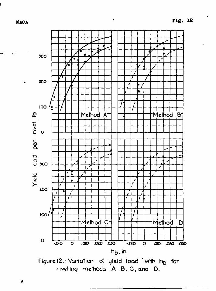
2. For riveting methods A, B, C, and D, the yieldload increases from low values for large negattvevalues of
~~. (See fig 12 )to high values for large positive
values of ● ●
3. For a given value of hb, rlvetlng method D givesslightly lower yield loade than methode. A, B, and C,(See fig, 12.)
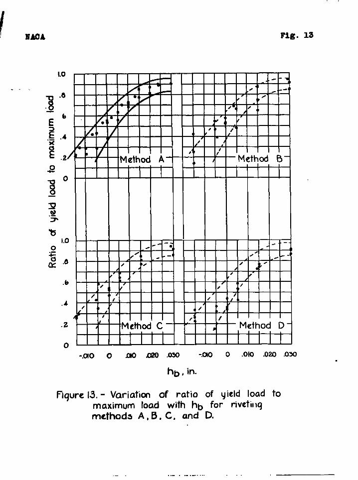
4. The ratio of yield load to max~mum load Increamesfrom values near zero for large”negative values ofhb to values near unity for large positive valuesof hb. (See fig. 13.)
5, When hb Is negative, the value of :ha- tendsito be nearly %orq regardless of the magnitude of .hb; whereas, when hb IU positlv.e, ha is approx-imately equal to hb, (See fig. 14.)
!/’
6
1.. ” .. .
““‘It“nM#rbe ‘that”-th..”p”tiosourous-d in .~ho-qqueosemethod of riveting, method D,”wao not suffieienk~y ‘radtto.give the same $~eld load as obtained for” riweta frtvenby a hand hammer or vibrating gun~ methMs”A~ BO and C- .0? the other hand, it may be that the squeese method ofrlvetlng alw~m gives lover yield loadm. Thin “polmt noedeto be .oleared up by further tests.
On the basi6 o’f’makimum load ah the sole criterionof ~uality of a riveted .~oint, hb should alyays benegative. When hb 30 negiaiive; howeTer, perm8nentdisplacement of the attaohed parts a“fte?a small per-centage of the maximum load has b~en applied may renderthe jotnt unfit for the service required, ●epeclally Ifthe loads are repeated. In addltfo?i, the excesalyedistortion of the Joint before .maxlhnamload io reachedwhen hb 18 negative and the relatively emala distortion
“ prior to failure when hb Is p~e~tive rendere a oomparlsonof quality on the baala of maximum .load”un~uetifleda
Eor the riirete on-the exterloe surfaces ok aireraft~lt hppears that”fluehnees -d yield load ae a measure oftlghtnese should be the criterion of quallty.
If hb io poeltive,” the ‘rivets will be relativel~tight but will protrude above the skin surface after driv-ing and, if hb ICInegative, the rivets will be approx-imately flush after driving but will not.be tl.ght. If ttie desired to aohieve.tightnes-s and fluehnosm In a singleoperation by holding hb equal to sero, very emall tol-.O?ancee”must be used In the dimension of both the riretHead.and the countersunk 4010. In this investigation aperfeotly flueh rivet was not obtained even when hb wasessentially zero: a small annular deproselon wan alwaycprpeent around the rivet head...
“Tho pkact~cal method” O* obtaiilin$rivets that aretight and perfeetly. flush may be to upe”.a”-def~nitelypoeoftlve *&lue of hb and then to -remove the portionQf tho rivet heaL that protrudes qbove the ekin surfaoeafter driving. The removal of the “protruding portion“of tlier%vet head red.uc.eeonly 611 htly the yield loadarid.tho’maximum load, $(see fig. 1 .)~.. . ...,. .
.-31vet@e method & - Il”i;etingmethod E differed from
methods AB B, C, and D in that a rovndhead ri.ve~rae .uoedinstead of a oountereunk-head rive% and the rivet waeIneerted from the side opposite the countersunk hole.

6
.
., . .
The inalti.ederig.le”afthe nounters.unk hole wau”var.iedfrom 30° to 82b and the sheet .thiokneeses var~ed from0.040 .to0.102 Inoh. B.lvetawere driven by method E,where the Inoluded “a”nglebf the countersunk hole was100°, but the increased” shank length required made Itdifftcult to produce .ounsistentl~ satisfactory fillingof the .countersunk hole. Because of this fact, theteat program wtie.lim~ted to head angles of not morethan 82°: “ “ .
. .
The tee~s”of”spedimens made by riveting method B’reyeal””that, within the range of anglea tested, the ‘rivbt~head angle” .9 haa.no effeot on the yield.lbadand”khe rna~imum l~ad. “ (See fig. 16.)
..:.”
~or”-the.range of sheet thloknesses used (t * 0.040to 0.102 $h.), the yield load and the maximum load tend. .to”bo high”er-when the riveted ~oints are made wtth t“hlnshte,etethan when made with thick sheets. (See”fig. 17. )
. . . . . ...
Q?!l!u2w of r-ults for rlvptin~ method”sC’and E“ -Riveting methods C and 33”are stmilar except for the type.of rmiv,etand the side of the Joint from which tke rivet
- 16.Ineefted...:- “-Riveting neth.od C gave yield loads and-, rn,a”x~mum’loads as”high ae or h.ighe~ than “methods A, B, and
IJ;the”r’efore,the highest values obtained by rfvetingmethods ~A, E- Cs and D are c“omparedwith the.oorrespond-..ing valueti-ol)tathedby method E. ,
.-.For riveting tiethod C; the.reeults for the ideal
value of hb = 0:000 inch and the arbitrary value ofhi = 0.020 inch are eelected for:comparleon w~th the re- “taulteof riveting method E, “ 6 .= 82°. Por the”rlvettaof method C with hb = Q.020 inch, the protruding ”portionof the rivet head was removed In order to ❑ake the.rivetmflush, ~hufa,all comparisons are made for rivets “thatare flush and have essentially the sams he-adangle.
In figure 18 are presented, for comparison”, load-dlsplscement curves for the Joints made by r~vetlng
: •eth~~s C and E with the foregoing values of hbe.
andkf~thodC with hb E 0.000 Inch shows a p.rogrossively “
.,moru i’avorable load-displacement relationship a6 theeheet t“hic.knessesincreaee. Method C with hh = 0.020,inch gives more favor~.ble load-displacement curves than “whan hb = 0“.000 inch. Method E .give”sIoed-displacementOurtieesomewhat more favorable than method C with ~b =0.020 inch.
1’.
7
~lgur~ 19 has been prepared to show the differencebetween the yield loads and the maximum loads for rivetingmethods C and n. The pointe plotted were obtained fromthe Ioad-diaplaoement ourvem of figure 180 ~lgurd 19 ‘.shows that for the range of ●beet-thicknesses teeted(0.040 to 0.102 In.): ~
Method E glvee the h3gheet yield loads and maximiimload~m “ .
Method O with hb = 0.020 Snob amd the protrudingpoktson ef the tivet head rehoved gave higher
rleld Zbade but gave.about the same maximum”oad ● e method C with hb = 0.000 Inoh.
COl10LUDI190RMABKS
l’rom the results of theee tests, it 1s oonoludedthat a oom arisen of the
? fualitr of maohine-oountereunk
riveted Jo nte on the bao o of maximum load alone 1snot ~ustified. For the r~vets on the exterior surfaoeeof airoraft, lt a peare that flushnesa and yteld load
Tae a measure of t ghtness should be the cr~terlor ofqualltym
The faot.that htgher yield Ioada were obtainedby riveting methods A, B, C, and D when hb waapositive than when hb wag negative indioatea thatthe driving of the rtvet .material.into the hole tofill It is the most Important faotor in obtainSngtight rivets. Beoauee riveting method 3 gave higheryield loads than methodo A, B, C, and D, It ie prob-able that, of the riveting methods investigated, thiemethod of riveting fill. the hole most completely. Inthe
frooess of dr#ving the rivets of method E, the shank
swel s along ite entire length, filllng “the oountersunk-rlvet hole progressively from bottom to top.
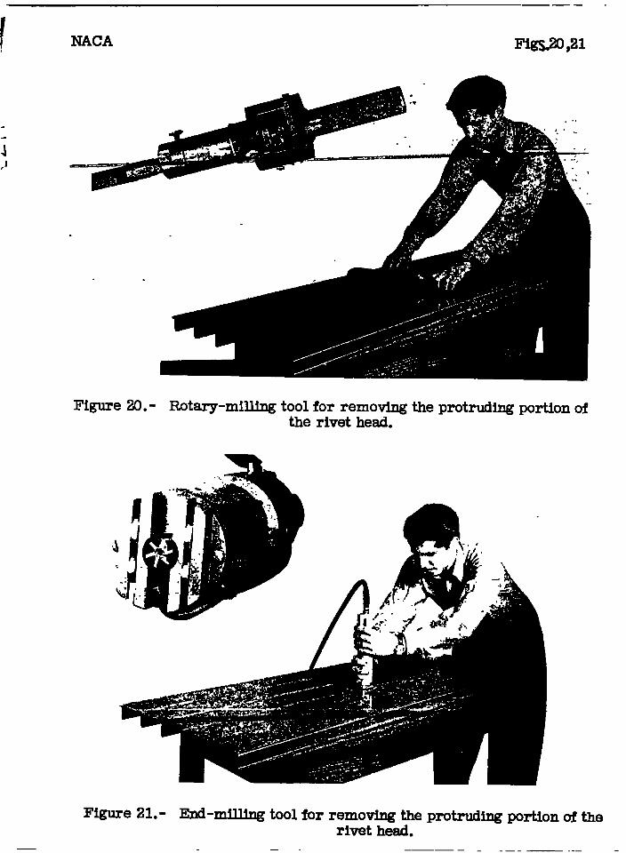
In add$tloq to produoing’tight rivets, any methodof riveting that completely fills the maohine oounter-ounk holes and removes the protruding portione of therivet heads after driving aleo provides a method ofobtaining a uniform surfaos finloh that 18 partloularlyuseful where extreme smoothness 1s requlred- Use ofeither of the milling toole shown in ftgures 20 and 21 -to remove the protru&ing portlone of the rivet heads willgive ● surfaoe suffioi.ently smooth that, when the surfaoe1- patnted and rubbed #own, the rivete oannot be deteoted. “If paint Is not-applied, a final rubb~ng down od fin3sh-in
foperation on the metax aupfaoe te re u~smd to aooom-
- pl ah the name result. Rivets Snatalled‘%x method E oould

8. . ,.
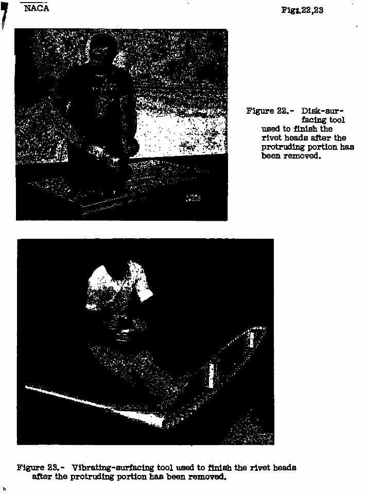
. . . “.not be deteoted b# IpopeetSon”of the unpainted surfacewhqn the final .finleh wa$ made with “either of the toolsehown in figures ?2 and 22!. “
It appsars that separate operatieis are. neoes-eary in the proeeduro of rlvetlng if the Joint 16 tobe of high quality w3th reepeot to both-tlghtneasthe #oiht and fluehneee of the rivet.
of
Langley Memorial Aeronautical Iiabpratory, .liational” Advlkory Committee; for Aer.onautie8,
“Langley ~leld, Va,.
.. -
. .
. . .. . .. .
“... ... .
.. .
.
.
. ..“
. .
.- , ..
.,.-,
.. . ... . .
.!.. . .,
.“
. .
.,
. . . ..“
. . . .. . . . .
... . . ., 1.. . . .:
.>. . .
..,.. . ..,. ..
. .. .. .
. ., ., .. . .
. . ., . . . . . .. .. .
. .. ..“.
.“
NACA
. .
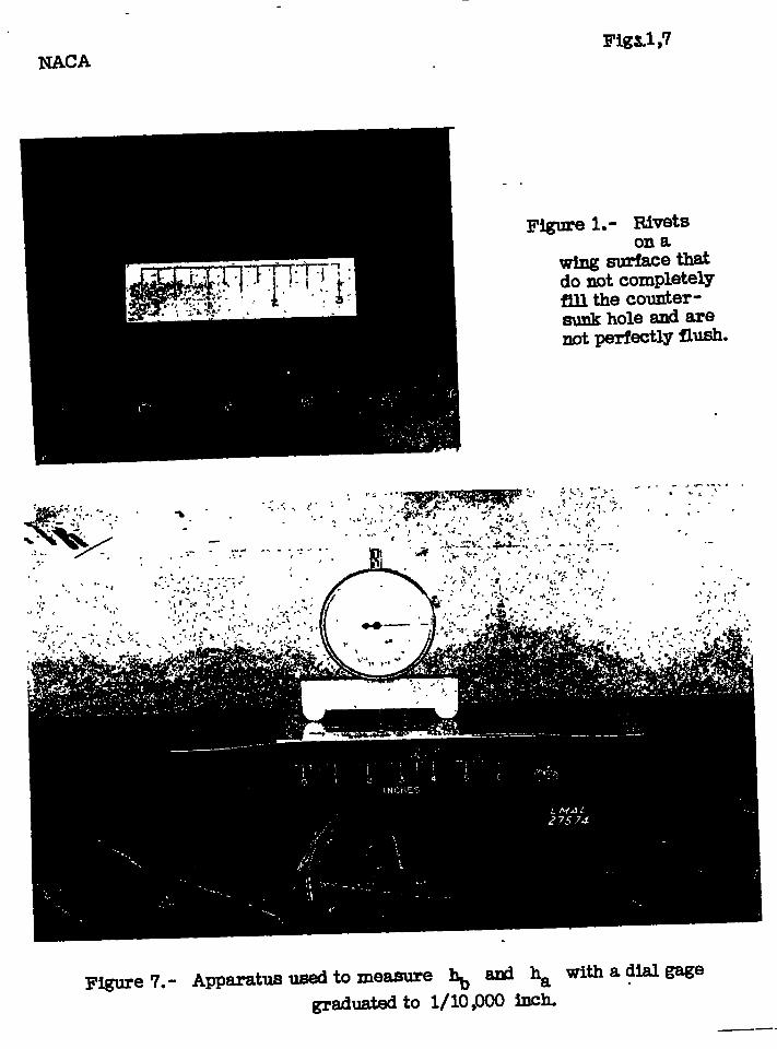
Figure 1.- ~~tson a
~aethatdo ~t completewfillthe counter-sunk hole and arenot@ectly flush.
Fi@Te 7.- Apparatus used to measure ~ a@ ha with a dialgage
grad- to 1/10,000 -h.——-

,. .-—. - -,. . .
.
rig, 2
.
t-1:1
T“-F
—Ho. 30. ,F axill -1
Figure 2.- Dimenmionaof maohlne-c=tersbnkrlvot- angleof oounterslnkused -
In rivetingmethods A, B, & ti D.
. .
.
. ,
-A
v’”-’\
deg
45
““”Y
6062
. C64@
—.
F--$“--+
,—\
‘1.. .
IMguro 3.- Dimensionsof roundhad rlvotand a@o ofcountcn.-ginkused In rivetingmethodE.
— -.
— ..— —.. ---- —--- .— --—
..
zig. 41
~ 1---1------ ~- -,--- r--l””
MVlh’atlng
11
rlat platennt ptite
BA
r-V3m’sting
.I
//
I?iJ-
FisdeqmmeBet
L_ rI
VibratingBucddng
-1---.4A---+vv-’
c
~lgwe 4.- Methodsof rivetingused in thita investi#3WIn.
-..—- —.— —— -- —
I’lg.5
— ..—. — —
.
10 rivetsin threerows
F~u..“,41.— ——
t
. . .-; 1
0::Ill
JGcl
I.—.-— — T—..- —! -..+.——
--...———.-- —. - -—- .—--J —-—— . —— .-— ?$———-r-r-””
4 rivetsin two rows
———.. —___ .—- .—. — .-—
J
2 rlvotaIn one row
.
~olntedrawn to eo4em
— . . . .—
.
.
.- .- .=... ... . . . .. ------- . .... . . . . . .. .
Positive ~
Beforedriving
1
Ilegatlve~
I?oaltive~
ha
Afterdriving
?Igure 6.- Illuetratiqnof ~ ~ ~ formachine-couatereunkrivets,

/‘J
. ..
NACA Fig. 8
Figure 8.- Test apparatus and specimen with 10 rivets in three rows.
hb, ina
+ 0.015 0 .Ooo ~ -.015
5400e“c1
plo
8amo1d
2 1000z
o0123 0123 0123
ITumlx3rof rivetrows
I
~gure 9,- V&iation of yield1- -d”~ loadwltinuuhr of rivet rows.:
/
.
NACA
>. .. . .
.
ii>c
u~-J
i%thod AFig. 10
Method 6 Mathod C Method D
’200
0
E13.-.# —,/
—El%H’---#-
[ I I I 1]I,!, J
-__lllll 11111 t--l- +-t-+ Ld-1-L-l4UU , I I I t- —— —
/ ‘Y“/
r
0l-l Ill hk=(looo:ln. I I I I
1“‘t-l-l I--I- +-F-(U F-I-t- r-l L-I-i- ~-i400 ~ I I I I 1 I I I I r ——
7——
#k/I IJSST
o ,h= O’.005”in I I I 1
400
200
0
400
200
0
400
00 0204 0.020401X?,040M .-
Di~ploccment, in.___ --- Maximum load — Permanent d]qiwement—-— DiqM~cement undw load o Yield Ioacl
fiqurc 10- Load -displacement curves for rivetinq
methods A, B, C, cmd D.
/ IIACA
. .
200
0-.OIO o .O1o mo 030 -MO o .ao 020 .030
hb, in.
Figure I l.- Variation of maximum load withhb for rivetiq methods A, B, C, and D.
NACA Fig. 12
.-. .W“o
- 200
nC3o 300—
Icxl
o
.
III
-.ao o .ao .020 Q30 -tllo o mmomx)hb, in.
Figure 12.- Variation of yield load “with hb forrlvet~nq methods A, 0, C, and D.
—
. .
rig. 13
mLo
o.-% .6
&
.b
D04b-1 1 1 1 I I 1 1 I/1A’1/
.4 , M
.2
0-.ao o lno m .030 -fno o .010 .020 .030
.
hb, in.
Fiqure 13.- Variation of ratio of yield load tomaximum load with hb for rivetil}qmethods A, B, C. and D.
.-. . ... ..- .. . ... . .

/
.
NAOA
>.. - .. . .
.—
Fig. 14
. . . . . .
:010
c.-.2
.030
.020
.010
0 .--.
-.010
I I I I
I I
“.ao 0 .010 .020 .mo -.ao o MOmomo
hb, in.
Rqure IA. - Variation d ha with hb for rivetinq
methods A, 0, C, and D.
I . .
I 1!
FigtwwM.- compari- cd yidd load ad maximum load fir rivets befbmand -r femod d tic muding pwtkm d the riwt h8ad.
I
1i
I1
I I

Itttllttilltttti
Fiqure lb.- Variation d yield bad and maximum load wifh riwt-head ~lc
for different Ihicknescs t fbr ri#inq method E.w*
1

—h20 m .m am m .100 m m .mo .= .m .mo
Sheet thkkmss, t, “n.
fiqurc 17.- Variation d yield load ~d maximum load with sheet
I’Mckncss for diffcfcnt ri~t -- aqlcs 0 * rivctinq method C.

i
t“o.040in t “0.051in. t’ooain. t ■0.W h. t =0.102in.
0 .01 .02 0 al .Oz o 01 0 01 .= o a CeDisplacement;;n.
------ Maximum load Permanent displacement—-— - Displacement under load o Yield load
Fiqurt 18.- Load - displacement curves for rivetinq methods C and E .

-., . . .
rig
“i+
!5po ., -. -r -..,. ~, + . . . .
m
?‘ -1- “
$&—
I‘? s
-/-n \
0 x
3(X)
1
I Im
t ‘I-t
400” Ll_IQ_1 I I
lx
L‘i
.-/
II
<
300 -–
s xs x I I I
1,
Method ~, in*+E.
xc CLooo [cc ~.020, .pwtrlldhg .
100 thead romovod
●0a1 .040 .060 ●080 ●100soot thlc16mBB.In.
19
~igure19.-hqparlson of YIJJldloadand~imum loadfor rivetingmethodaOamn.
—— —,
.
i,1
NACA Fmsa,zl
.
Figure 20.- Rotary-millingtoolfor removing the protrudingthe rivet head.
portion of
Figure 21.- End-mjlling tool for removing the protruding portion of therivet head.
— — — .—--— ..—
7 NACA
Y
Figure 23.- Vibrating-surfacing tool used to fhish the rivet headsafter the protrding portion has been removed.
Fig&22,23 “
Figure 2
rivet
protrbeen
2m- Disk-sur-facing tool
to finish theheads tier thetihg portion hasremoved.

.
Illllllmlim L.3-117601~ 2_