Embed Size (px)
Citation preview

Wilo Star Residential Wet Rotor Circulators
Installation and operating instructions
50-1
3-00
2-04
15

2 50-13-002-0415
Figure 1
Figure 2
Figure 3

3 50-13-002-0415
Figure 4
Figure 5
NL
NL
N L
NL
5A
5B 5C

4 50-13-002-0415
Figure 6
Figure 7
Figure 8
NML
L
N
~1
5 50-13-002-0415
Table of contents Page1 General 62 Safety 63 Transport and interim storage 64 Intended use (Application) 65 Technical data 76 Description and function 77 Installation and electrical connection 88 Start up 89 Maintenance / Service 9
10 Faults, causes and remedies 9
6 50-13-002-0415
1 General
1.1 About this documentThese Installation and Operating Instructions form an integral part of the unit. They must be kept close to the unit and in readiness whenever required. Precise observance of these instructions is a pre-condition for use of the unit for the intended purpose and for its correct operation. These Installation and Operating Instructions conform to the relevant version of the equipment and the underlying safety standards valid at the time of going to press.
2 SafetyThese instructions contain important information which must be followed when installing and operating the pump. It is therefore imperative that they be read by both the installer and the operator before the circulator is installed or started up. Both the general safety instructions in the ‘Safety precautions’ section and those in subsequent sections indicated by danger symbols should be carefully observed.
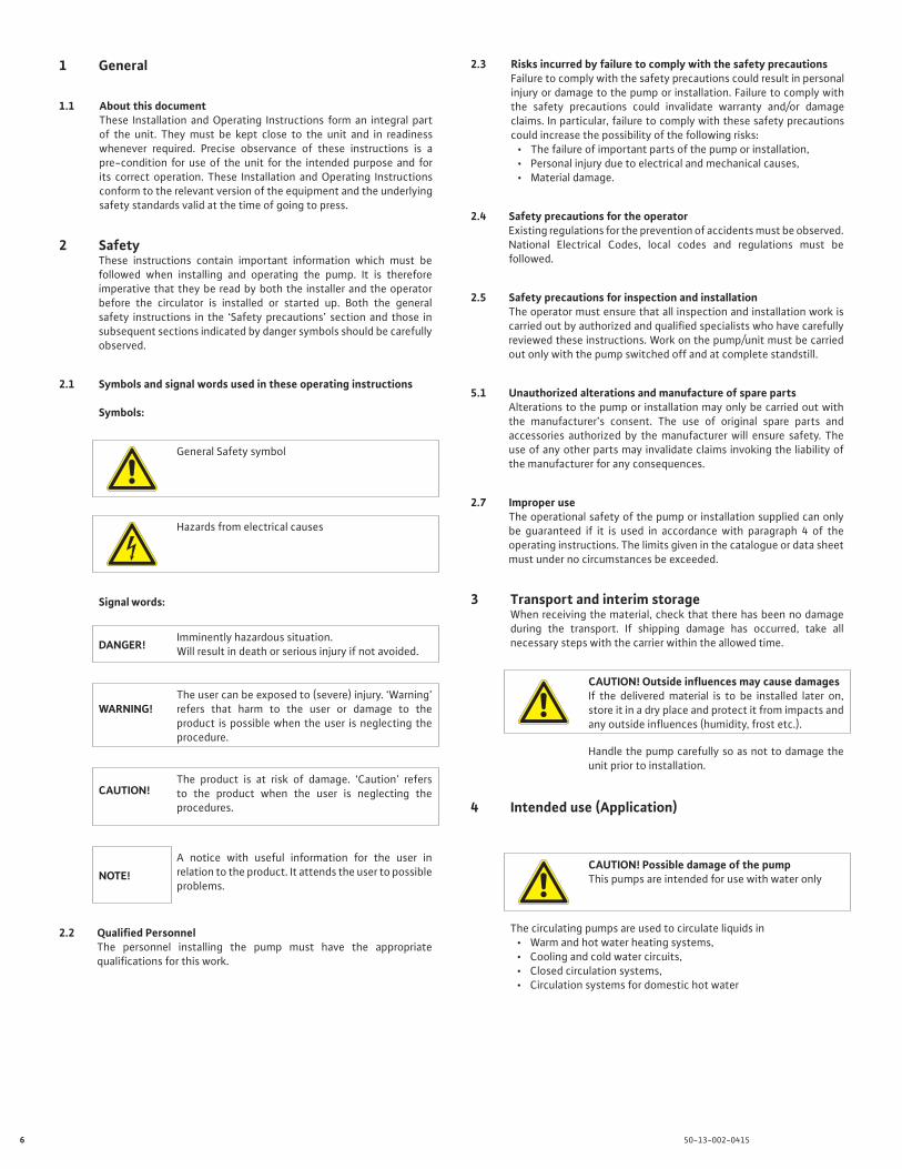
2.1 Symbols and signal words used in these operating instructions
Symbols:
General Safety symbol
Hazards from electrical causes
Signal words:
DANGER!Imminently hazardous situation.Will result in death or serious injury if not avoided.
WARNING!The user can be exposed to (severe) injury. ‘Warning’ refers that harm to the user or damage to the product is possible when the user is neglecting the procedure.
CAUTION!The product is at risk of damage. ‘Caution’ refers to the product when the user is neglecting the procedures.
NOTE!A notice with useful information for the user in relation to the product. It attends the user to possible problems.
2.2 Qualified PersonnelThe personnel installing the pump must have the appropriate qualifications for this work.
2.3 Risks incurred by failure to comply with the safety precautionsFailure to comply with the safety precautions could result in personal injury or damage to the pump or installation. Failure to comply with the safety precautions could invalidate warranty and/or damage claims. In particular, failure to comply with these safety precautions could increase the possibility of the following risks:
• The failure of important parts of the pump or installation,• Personal injury due to electrical and mechanical causes,• Material damage.
2.4 Safety precautions for the operatorExisting regulations for the prevention of accidents must be observed.National Electrical Codes, local codes and regulations must be followed.
2.5 Safety precautions for inspection and installationThe operator must ensure that all inspection and installation work is carried out by authorized and qualified specialists who have carefully reviewed these instructions. Work on the pump/unit must be carried out only with the pump switched off and at complete standstill.
5.1 Unauthorized alterations and manufacture of spare partsAlterations to the pump or installation may only be carried out with the manufacturer’s consent. The use of original spare parts and accessories authorized by the manufacturer will ensure safety. The use of any other parts may invalidate claims invoking the liability of the manufacturer for any consequences.
2.7 Improper useThe operational safety of the pump or installation supplied can only be guaranteed if it is used in accordance with paragraph 4 of the operating instructions. The limits given in the catalogue or data sheet must under no circumstances be exceeded.
3 Transport and interim storageWhen receiving the material, check that there has been no damage during the transport. If shipping damage has occurred, take all necessary steps with the carrier within the allowed time.
CAUTION! Outside influences may cause damagesIf the delivered material is to be installed later on, store it in a dry place and protect it from impacts and any outside influences (humidity, frost etc.).
Handle the pump carefully so as not to damage the unit prior to installation.
4 Intended use (Application)
CAUTION! Possible damage of the pumpThis pumps are intended for use with water only
The circulating pumps are used to circulate liquids in• Warm and hot water heating systems,• Cooling and cold water circuits,• Closed circulation systems,• Circulation systems for domestic hot water
7 50-13-002-0415
Permissible liquids and requirements:• Domestic hot water. In open domestic hot water systems the
pumps should be in bronze body and in accordance with all other specific drinking water laws.
• Heating water acc. the requirements of accepted standards of water quality in heating systems.
• Water and water/glycol mixtures in a maximum ratio up to 1:1. Glycol mixtures require a reassessment of pump hydraulic data in line with the increased viscosity and depending on mixing ratios. Only approved makes of additives with corrosion inhibitors must be used in strict compliance with manufacturers’ instructions.
For use of other kinds of liquids consult WILO first.
5 Technical data
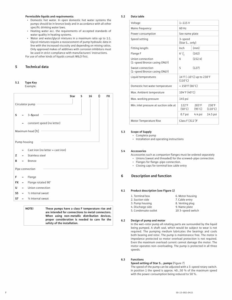
5.1 Type KeyExample:
Star S 16 () FX
Circulator pump
S = 3-Speed
= constant speed (no letter)
Maximum head [ft]
Pump housing
= Cast iron (no letter = cast iron)
Z = Stainless steel
B = Bronze
Pipe connection
F = Flange
FX = Flange rotated 90°
U = Union connection
S5 = ½ Internal sweat
S7 = ¾ Internal sweat
NOTE! These pumps have a class F temperature rise and are intended for connections to metal connectors. When using non-metallic distribution devices, proper consideration is needed to care for the safety of the installation.
5.2 Data table
Voltage 1~115 V
Mains frequency 60 Hz
Power consumption See name plate
Speed setting 3-speed (Star S… only)
Fitting length: Inch (mm)
Flange F 6 3/8 (162)
Union connection (1-speed Bronze casing ONLY)
6 (152.4)
Sweat connection (1-speed Bronze casing ONLY)
5 (127)
Liquid temperatures 14°F (-10°C) up to 230°F (110°C)
Domestic hot water temperature < 150°F (66°C)
Max. Ambient temperature 104°F (40°C)
Max. working pressure 145 psi
Min. inlet pressure at suction side at 122°F(50°C)
203°F(95°C)
230°F(110°C)
0.7 psi 4.4 psi 14.5 psi
Motor Temperature Rise Class F (311°)F
5.3 Scope of Supply• Complete pump• Installation and operating instructions
5.4 AccessoriesAccessories such as companion flanges must be ordered separately
• Unions (sweat and threaded) for the screwed-pipe connection.• Flanges for flange-pipe connection.• Closing caps for terminal box cable entry
6 Description and function
6.1 Product description (see Figure 1)
1. Terminal box2. Suction side3. Pump housing 4. Discharge side5. Condensate outlet
6. Motor housing7. Cable entry8. Venting plug9. Name plate10 3-speed switch
6.2 Design of pump and motorIn the wet-rotor pump all rotating parts are surrounded by the liquid being pumped. A shaft seal, which would be subject to wear is not required. The pumping medium lubricates the bearings and cools both bearing and rotor. The pump is maintenance free. The motor is impedance protected so motor overload protection is not required. Even the maximum overload current cannot damage the motor. The motor operates non-overloading. The pump is protected in all three speeds.
6.3 FunctionsSpeed setting of Star S… pumps (Figure 7) The speed of the pump can be adjusted with a 3-speed rotary switch.In position 1 the speed is approx. 40...50 % of the maximum speed with the power consumption being reduced to 50 %.
8 50-13-002-0415
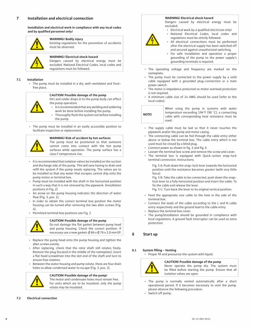
7 Installation and electrical connection
Installation and electrical work in compliance with any local codes and by qualified personnel only!
WARNING! Bodily injuryExisting regulations for the prevention of accidents must be observed.
WARNING! Electrical shock hazardDangers caused by electrical energy must be excluded. National Electrical Codes, local codes and regulations must be followed.
7.1 Installation• The pump must be installed in a dry, well-ventilated and frost-
free place.
CAUTION! Possible damage of the pumpDirt and solder drops in to the pump body can effect the pump operation.
• It is recommended that any welding and soldering work be done before installing the pump.
• Thoroughly flush the system out before installing the pump.
• The pump must be installed in an easily accessible position to facilitate inspection or replacement.
WARNING! Risk of accident by hot surfacesThe pump must be positioned so that someone cannot come into contact with the hot pump surfaces while operation. The pump surface has a class F temperature rise.
• It is recommended that isolation valves be installed on the suction and discharge side of the pump. This will save having to drain and refill the system if the pump needs replacing. The valves are to be installed so that any water that escapes cannot drip onto the pump motor or terminal box.
• Pump must be installed with the shaft in the horizontal position in such a way that it is not stressed by the pipework. (Installation positions in Fig. 2)
• An arrow on the pump housing indicates the direction of water flow (Fig. 3, pos. 1).
• In order to obtain the correct terminal box position the motor housing can be turned after removing the two allen screws (Fig. 4).
• Permitted terminal box positions see Fig. 2
CAUTION! Possible damage of the pumpDo not damage the flat gasket between pump head and pump housing. Check the correct position. If necessary use a new gasket: Ø 86 x Ø 76 x 2.0 mm EP.
• Replace the pump head onto the pump housing and tighten the allen screws evenly.
• After replacing, check that the rotor shaft still rotates freely. Remove the plug (located in the middle of the nameplate), insert a flat head screwdriver into the slot end of the shaft and turn to ensure free rotation.
• Between the stator housing and pump volute, there are four drain holes to allow condensed water to escape (Fig. 3, pos. 2).
CAUTION! Possible damage of the pump!The motor and condensate holes must remain free.For units which are to be insulated, only the pump volute may be insulated.
7.2 Electrical connection
WARNING! Electrical shock hazardDangers caused by electrical energy must be excluded.
• Electrical work by a qualified electrician only!• National Electrical Codes, local codes and
regulations must be strictly followed.• All electrical connections must be performed
after the electrical supply has been switched off and secured against unauthorized switching.
• For safe installation and operation a proper grounding of the pump to the power supply’s grounding terminals is required.
• The operating voltage and frequency are marked on the nameplate.
• The pump must be connected to the power supply by a solid cable equipped with a grounded plug-connection or a main power switch.
• The motor is impedance protected so motor overload protection is not required.
• A minimum cable size of 14 AWG should be used (refer to the local codes).
NOTE!
When using the pump in systems with water temperature exceeding 194°F (90 °C), a connecting cable with corresponding heat resistance must be used.
• The supply cable must be laid so that it never touches the pipework and/or the pump and motor casing.
• The connecting cable can be fed through the cable entry either above or below the terminal box. The cable entry which is not used must be closed by a blind plug.
• Connect power as shown in fig. 5 and fig. 6• Loosen the terminal box screw and remove the screw and cover.• The terminal box is equipped with Quick-action snap-lock
terminal connection. Instructions:
Fig. 5 A: Push down the snap-lock lever towards the horizontal position until the resistance becomes greater (with very little force) Fig. 5 B: Take the cable to be connected, push down the snap-lock lever to a fully horizontal position and insert the cable. To fix the cable end release the lever.Fig. 5 C: Turn back the lever to its original vertical position.
• Feed the appropriate size cable to the hole in the side of the terminal box.
• Connect the leads of the cable according to the L and N cable entry respectively and the ground lead to the cable entry.
• Replace the terminal box cover.• The pump/installation should be grounded in compliance with
local regulations. A ground fault interrupter can be used as extra protection.
8 Start up
8.1 System filling - Venting• Proper fill and pressurize the system with liquid.
CAUTION! Possible damage of the pumpNever operate the pump dry. The system must be filled before starting the pump. Ensure that all isolation valves are open.
• The pump is normally vented automatically after a short operational period. If it becomes necessary to vent the pump, please observe the following procedure:
• Switch off pump.
9 50-13-002-0415
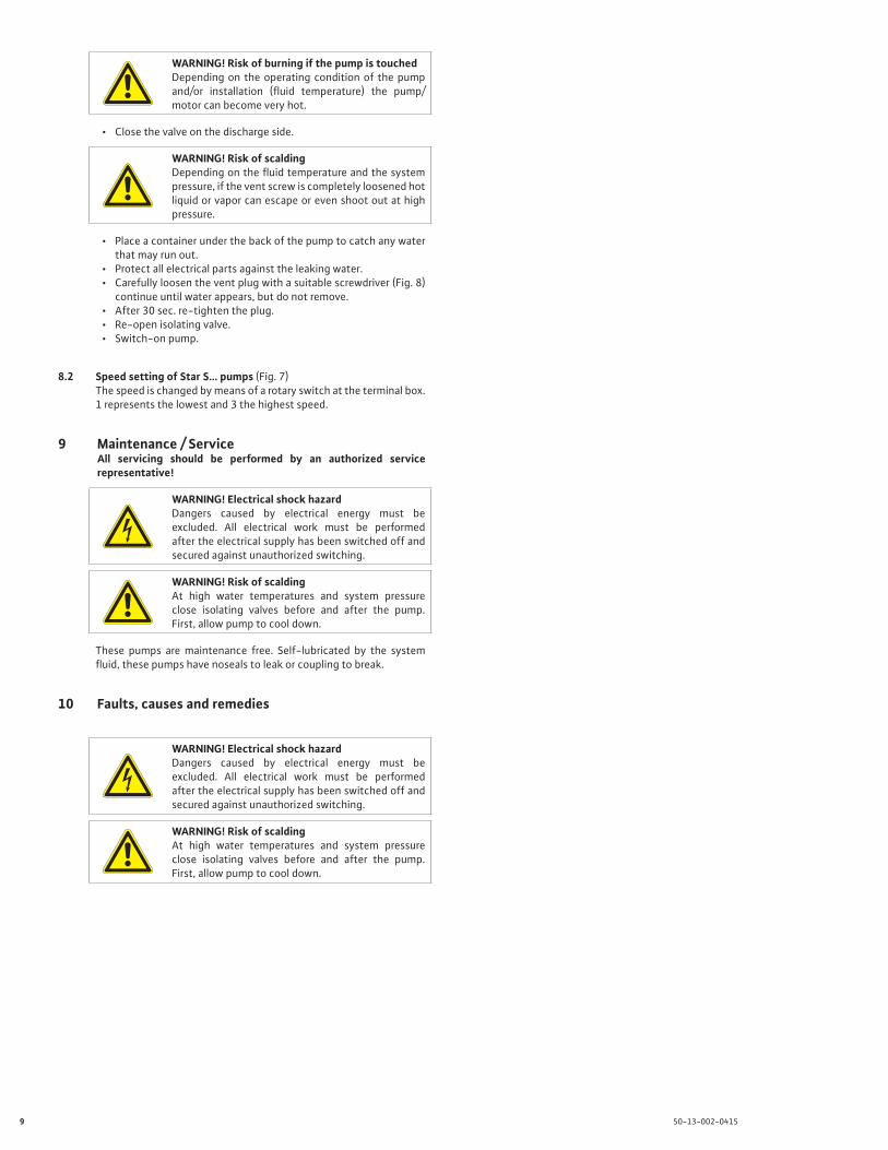
WARNING! Risk of burning if the pump is touchedDepending on the operating condition of the pump and/or installation (fluid temperature) the pump/motor can become very hot.
• Close the valve on the discharge side.
WARNING! Risk of scaldingDepending on the fluid temperature and the system pressure, if the vent screw is completely loosened hot liquid or vapor can escape or even shoot out at high pressure.
• Place a container under the back of the pump to catch any water that may run out.
• Protect all electrical parts against the leaking water.• Carefully loosen the vent plug with a suitable screwdriver (Fig. 8)
continue until water appears, but do not remove.• After 30 sec. re-tighten the plug.• Re-open isolating valve.• Switch-on pump.
8.2 Speed setting of Star S… pumps (Fig. 7)The speed is changed by means of a rotary switch at the terminal box. 1 represents the lowest and 3 the highest speed.
9 Maintenance / ServiceAll servicing should be performed by an authorized service representative!
WARNING! Electrical shock hazardDangers caused by electrical energy must be excluded. All electrical work must be performed after the electrical supply has been switched off and secured against unauthorized switching.
WARNING! Risk of scaldingAt high water temperatures and system pressure close isolating valves before and after the pump. First, allow pump to cool down.
These pumps are maintenance free. Self-lubricated by the system fluid, these pumps have noseals to leak or coupling to break.
10
Faults, causes and remedies
WARNING! Electrical shock hazardDangers caused by electrical energy must be excluded. All electrical work must be performed after the electrical supply has been switched off and secured against unauthorized switching.
WARNING! Risk of scaldingAt high water temperatures and system pressure close isolating valves before and after the pump. First, allow pump to cool down.
10 50-13-002-0415
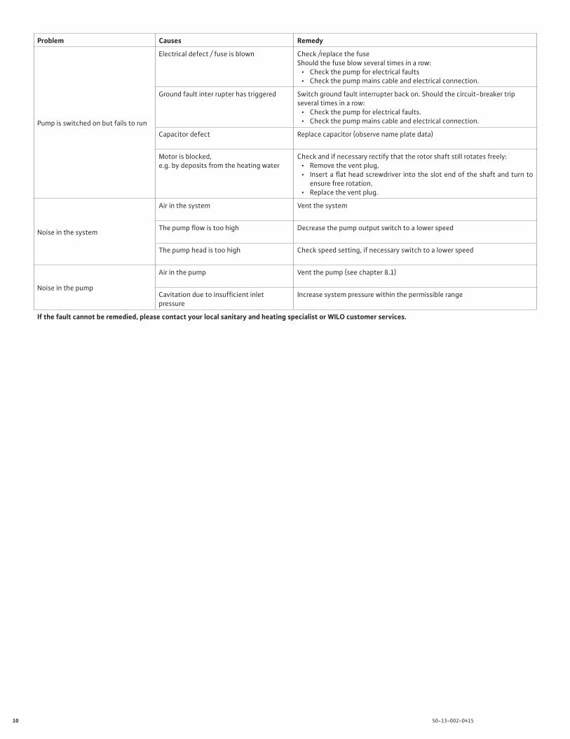
Problem Causes Remedy
Pump is switched on but fails to run
Electrical defect / fuse is blown Check /replace the fuseShould the fuse blow several times in a row:
• Check the pump for electrical faults• Check the pump mains cable and electrical connection.
Ground fault inter rupter has triggered Switch ground fault interrupter back on. Should the circuit-breaker trip several times in a row:
• Check the pump for electrical faults.• Check the pump mains cable and electrical connection.
Capacitor defect Replace capacitor (observe name plate data)
Motor is blocked, e.g. by deposits from the heating water
Check and if necessary rectify that the rotor shaft still rotates freely:• Remove the vent plug,• Insert a flat head screwdriver into the slot end of the shaft and turn to
ensure free rotation,• Replace the vent plug.
Noise in the system
Air in the system Vent the system
The pump flow is too high Decrease the pump output switch to a lower speed
The pump head is too high Check speed setting, if necessary switch to a lower speed
Noise in the pump
Air in the pump Vent the pump (see chapter 8.1)
Cavitation due to insufficient inlet pressure
Increase system pressure within the permissible range
If the fault cannot be remedied, please contact your local sanitary and heating specialist or WILO customer services.

11 50-13-002-0415

Wilo Star - Installation and Operation Manual
WILO USA LLC
Tel: 888-945-6872Web: www.wilo-usa.comEmail: [email protected]
Wilo Canada Inc.
Tel: 866-945-6236Web: www.wilo-canada.comEmail: [email protected]
Wilo Mexico
Tel: + 52 55 5586 3209Web: www.wilo-mexico.comEmail: [email protected]