Embed Size (px)
Citation preview
Page 1 www.wima.com
WIMA Film Capacitors
Page 2 www.wima.com
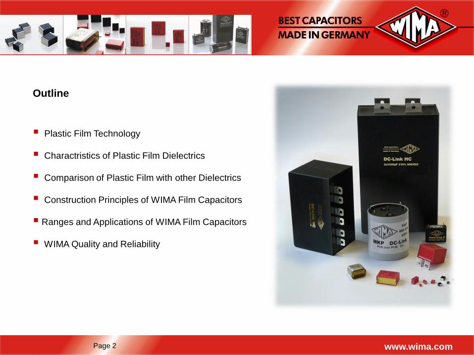
Plastic Film Technology
Charactristics of Plastic Film Dielectrics
Comparison of Plastic Film with other Dielectrics
Construction Principles of WIMA Film Capacitors
Ranges and Applications of WIMA Film Capacitors
WIMA Quality and Reliability
Outline
Page 3 www.wima.com
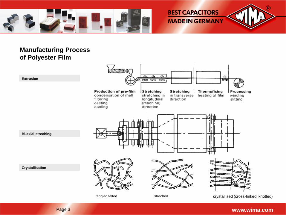
Manufacturing Process
of Polyester Film
Extrusion
Bi-axial streching
Crystallisation
tangled felted streched crystallised (cross-linked, knotted)
Page 4 www.wima.com
Film Technology
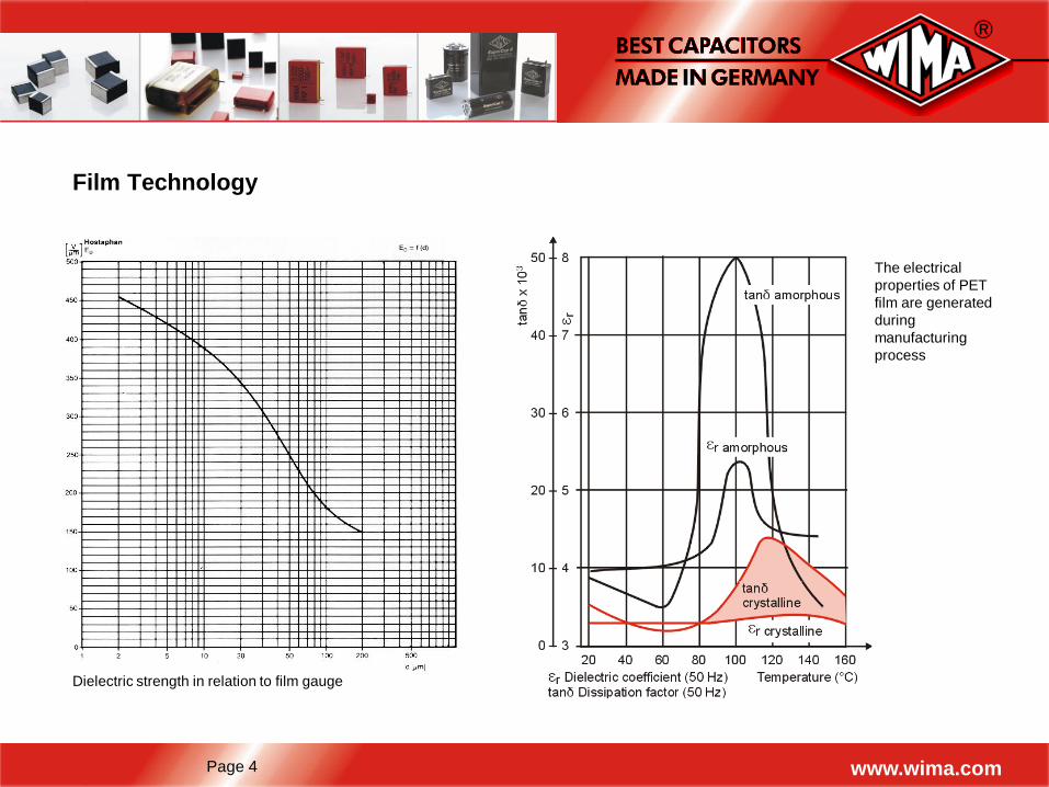
Dielectric strength in relation to film gauge
The electrical
properties of PET
film are generated
during
manufacturing
process
Page 5 www.wima.com
Film Technology
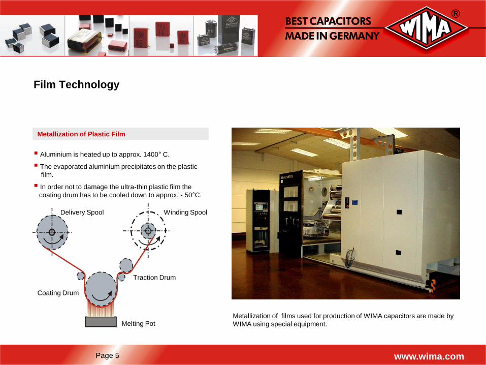
Metallization of Plastic Film
Aluminium is heated up to approx. 1400° C.
The evaporated aluminium precipitates on the plastic
film.
In order not to damage the ultra-thin plastic film the
coating drum has to be cooled down to approx. - 50°C.
Delivery Spool Winding Spool
Melting Pot
Coating Drum
Traction Drum
Metallization of films used for production of WIMA capacitors are made by
WIMA using special equipment.
Page 6 www.wima.com
Polyester (PET) Film
Typical Applications
Decoupling/Bypassing
Coupling/Blocking
Smoothing etc.
Film Properties
Max. operating temperature: +100°C
Film thickness: > 0.5 µm
Advantageous price/performance ratio
Advantageous capacitance/volume ratio
Substitution of ceramic, electrolytic
and tantalum capacitors
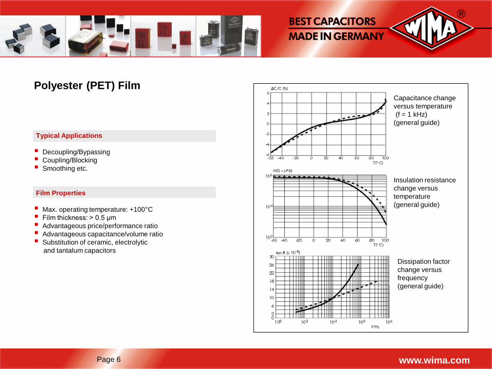
Insulation resistance
change versus
temperature
(general guide)
Dissipation factor
change versus
frequency
(general guide)
Capacitance change
versus temperature
(f = 1 kHz)
(general guide)
Page 7 www.wima.com
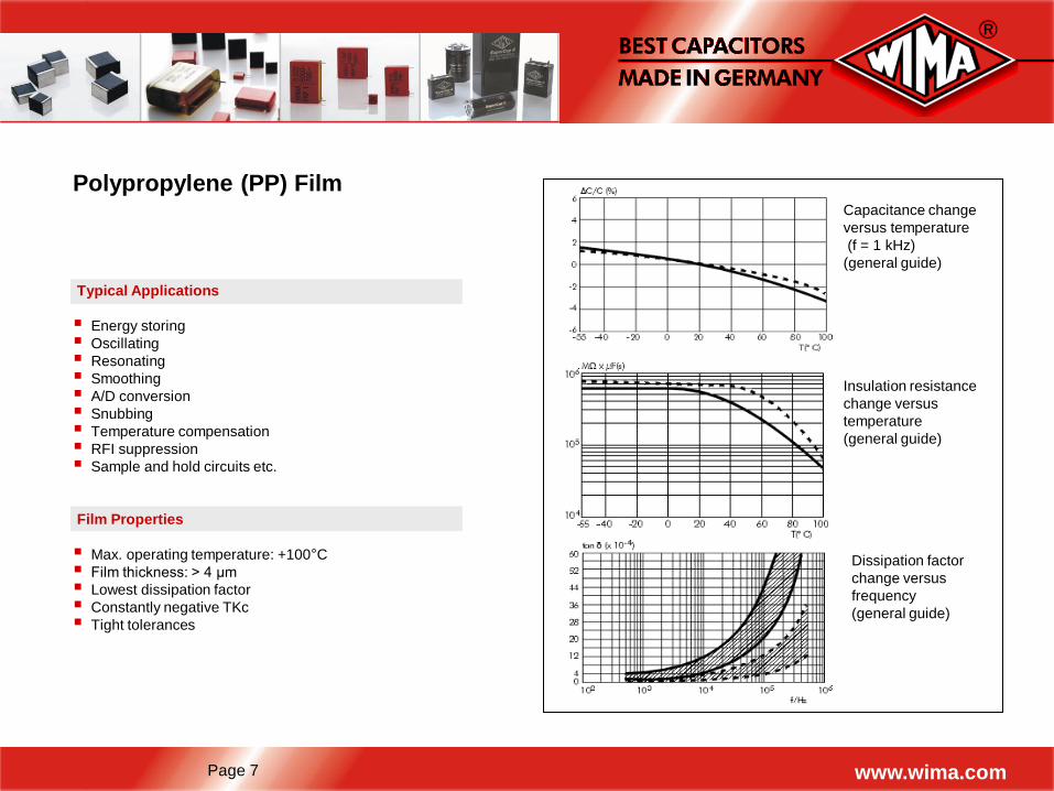
Polypropylene (PP) Film
Typical Applications
Energy storing
Oscillating
Resonating
Smoothing
A/D conversion
Snubbing
Temperature compensation
RFI suppression
Sample and hold circuits etc.
Film Properties
Max. operating temperature: +100°C
Film thickness: > 4 µm
Lowest dissipation factor
Constantly negative TKc
Tight tolerances
Insulation resistance
change versus
temperature
(general guide)
Dissipation factor
change versus
frequency
(general guide)
Capacitance change
versus temperature
(f = 1 kHz)
(general guide)
Page 8 www.wima.com
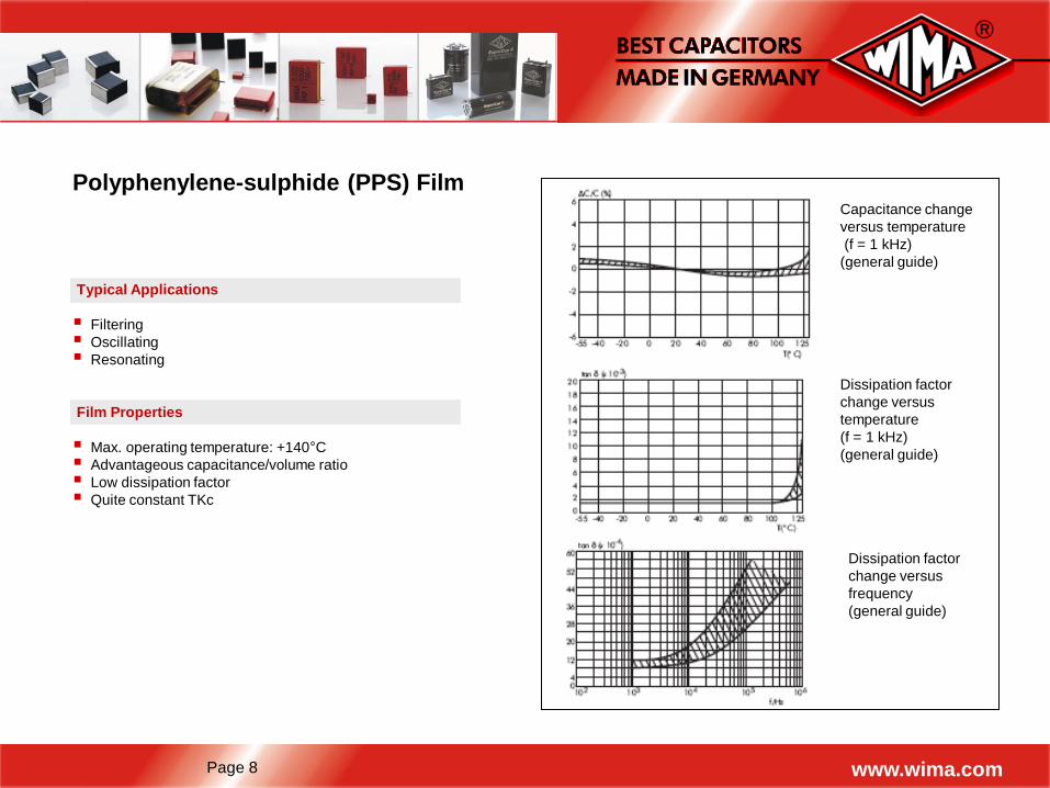
Polyphenylene-sulphide (PPS) Film
Typical Applications
Filtering
Oscillating
Resonating
Film Properties
Max. operating temperature: +140°C
Advantageous capacitance/volume ratio
Low dissipation factor
Quite constant TKc
Dissipation factor
change versus
temperature
(f = 1 kHz)
(general guide)
Dissipation factor
change versus
frequency
(general guide)
Capacitance change
versus temperature
(f = 1 kHz)
(general guide)
Page 9 www.wima.com
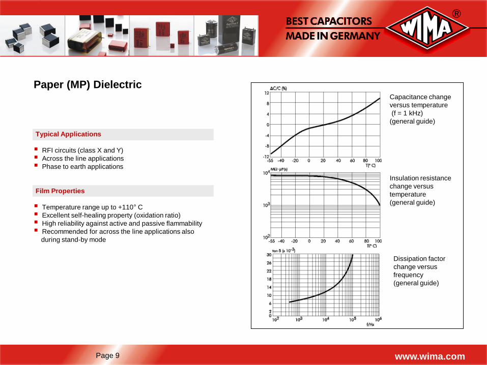
Paper (MP) Dielectric
Typical Applications
RFI circuits (class X and Y)
Across the line applications
Phase to earth applications
Film Properties
Temperature range up to +110° C
Excellent self-healing property (oxidation ratio)
High reliability against active and passive flammability
Recommended for across the line applications also
during stand-by mode
Insulation resistance
change versus
temperature
(general guide)
Dissipation factor
change versus
frequency
(general guide)
Capacitance change
versus temperature
(f = 1 kHz)
(general guide)
Page 10 www.wima.com
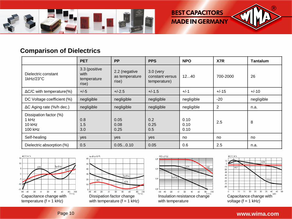
Comparison of Dielectrics
PET PP PPS NPO X7R Tantalum
Dielectric constant
1kHz/23°C
3.3 (positive
with
temperature
rise)
2.2 (negative
as temperature
rise)
3.0 (very
constant versus
temperature)
12...40 700-2000 26
ΔC/C with temperature(%) +/-5 +/-2.5 +/-1.5 +/-1 +/-15 +/-10
DC Voltage coefficient (%) negligible negligible negligible negligible -20 negligible
ΔC Aging rate (%/h dec.) negligible negligible negligible negligible 2 n.a.
Dissipation factor (%)
1 kHz
10 kHz
100 kHz
0.8
1.5
3.0
0.05
0.08
0.25
0.2
0.25
0.5
0.10
0.10
0.10
2.5 8
Self-healing yes yes yes no no no
Dielectric absorption (%) 0.5 0.05...0.10 0.05 0.6 2.5 n.a.
Capacitance change with
temperature (f = 1 kHz)
Dissipation factor change
with temperature (f = 1 kHz)
Insulation resistance change
with temperature
Capacitance change with
voltage (f = 1 kHz)
Page 11 www.wima.com
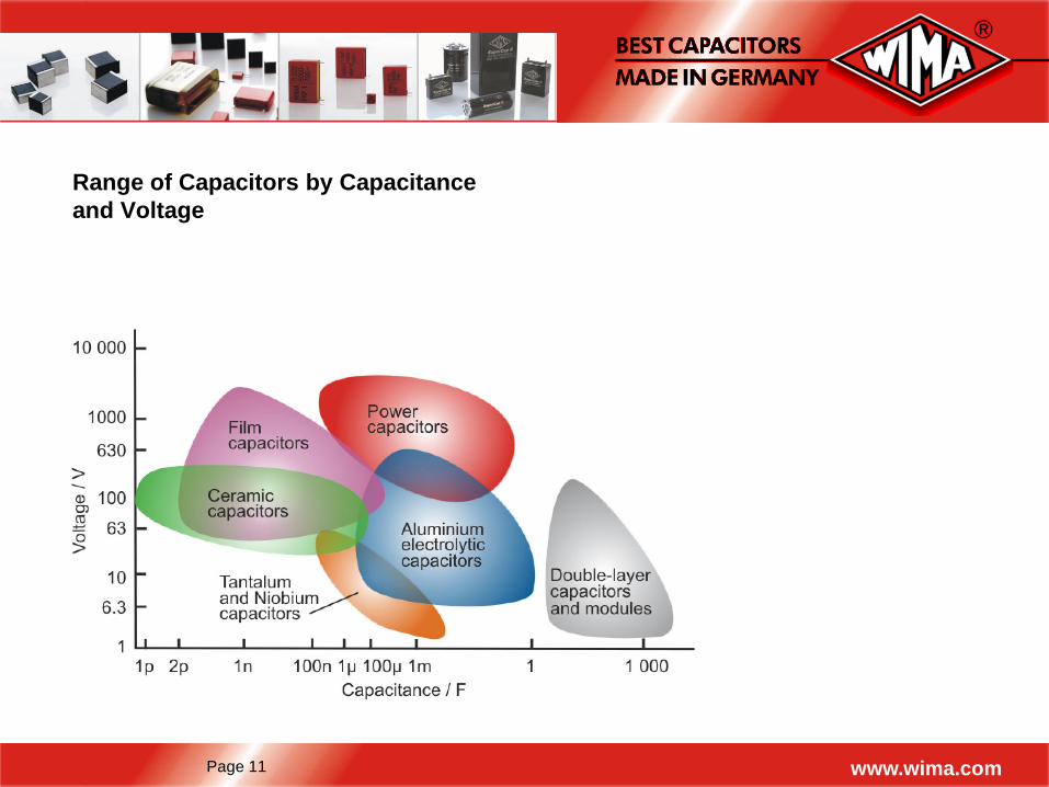
Range of Capacitors by Capacitance
and Voltage
Page 12 www.wima.com
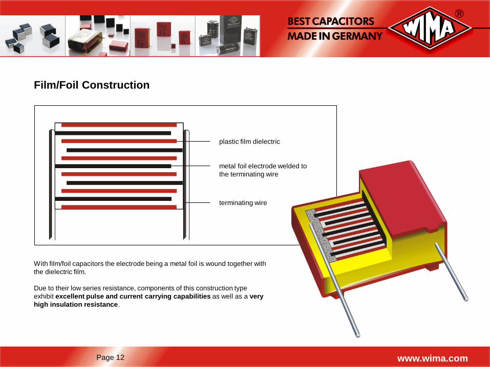
Film/Foil Construction
plastic film dielectric
metal foil electrode welded to
the terminating wire
terminating wire
With film/foil capacitors the electrode being a metal foil is wound together with
the dielectric film.
Due to their low series resistance, components of this construction type
exhibit excellent pulse and current carrying capabilities as well as a very
high insulation resistance.
Page 13 www.wima.com
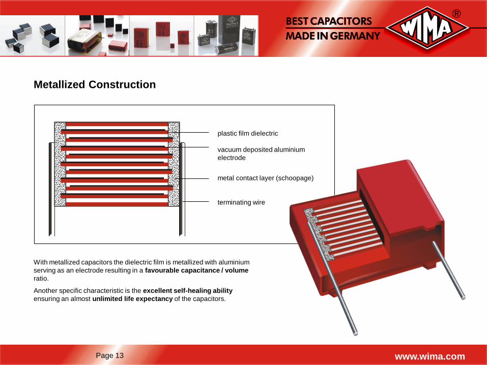
Metallized Construction
plastic film dielectric
vacuum deposited aluminium
electrode
metal contact layer (schoopage)
terminating wire
With metallized capacitors the dielectric film is metallized with aluminium
serving as an electrode resulting in a favourable capacitance / volume
ratio.
Another specific characteristic is the excellent self-healing ability
ensuring an almost unlimited life expectancy of the capacitors.
Page 14 www.wima.com
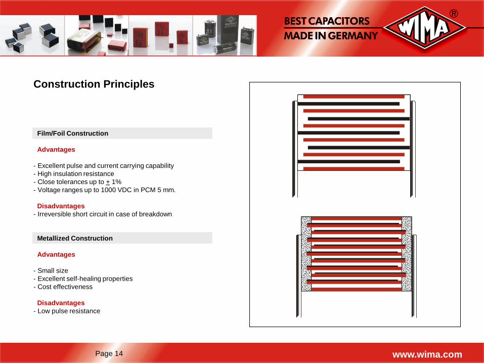
Construction Principles
Film/Foil Construction
Advantages
- Excellent pulse and current carrying capability
- High insulation resistance
- Close tolerances up to + 1%
- Voltage ranges up to 1000 VDC in PCM 5 mm.
Disadvantages
- Irreversible short circuit in case of breakdown
Metallized Construction
Advantages
- Small size
- Excellent self-healing properties
- Cost effectiveness
Disadvantages
- Low pulse resistance
Page 15 www.wima.com
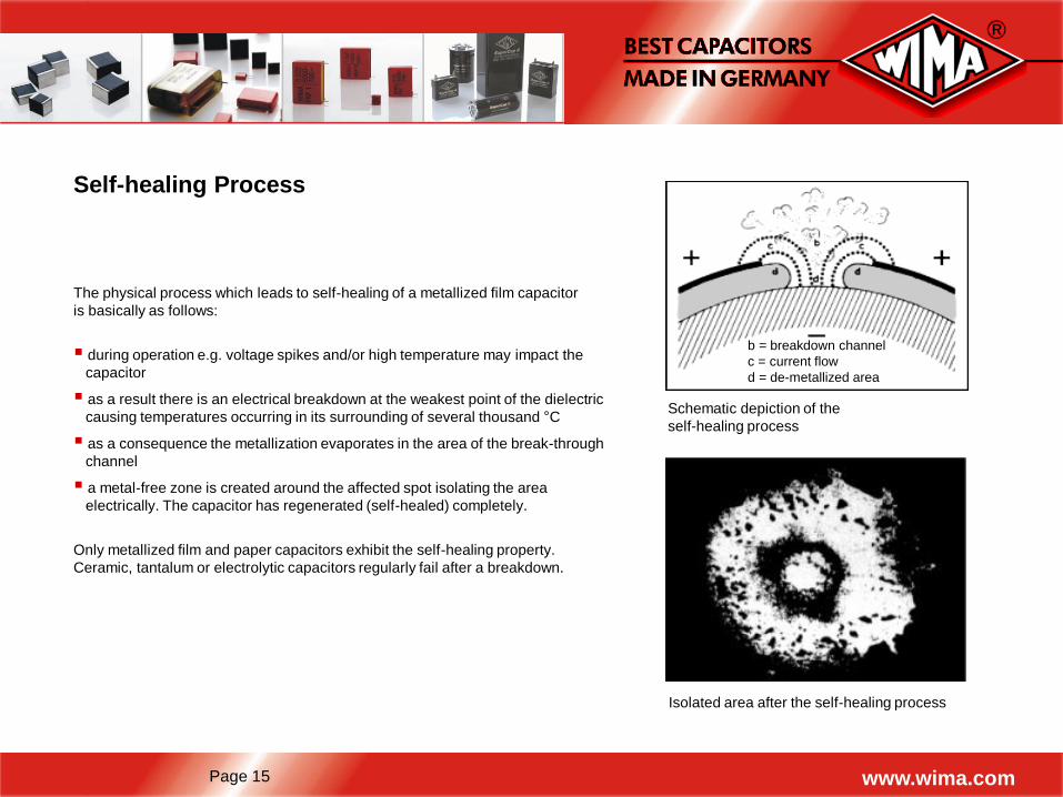
Self-healing Process
Schematic depiction of the
self-healing process
Isolated area after the self-healing process
The physical process which leads to self-healing of a metallized film capacitor
is basically as follows:
during operation e.g. voltage spikes and/or high temperature may impact the
capacitor
as a result there is an electrical breakdown at the weakest point of the dielectric
causing temperatures occurring in its surrounding of several thousand °C
as a consequence the metallization evaporates in the area of the break-through
channel
a metal-free zone is created around the affected spot isolating the area
electrically. The capacitor has regenerated (self-healed) completely.
Only metallized film and paper capacitors exhibit the self-healing property.
Ceramic, tantalum or electrolytic capacitors regularly fail after a breakdown.
b = breakdown channel
c = current flow
d = de-metallized area
Page 16 www.wima.com
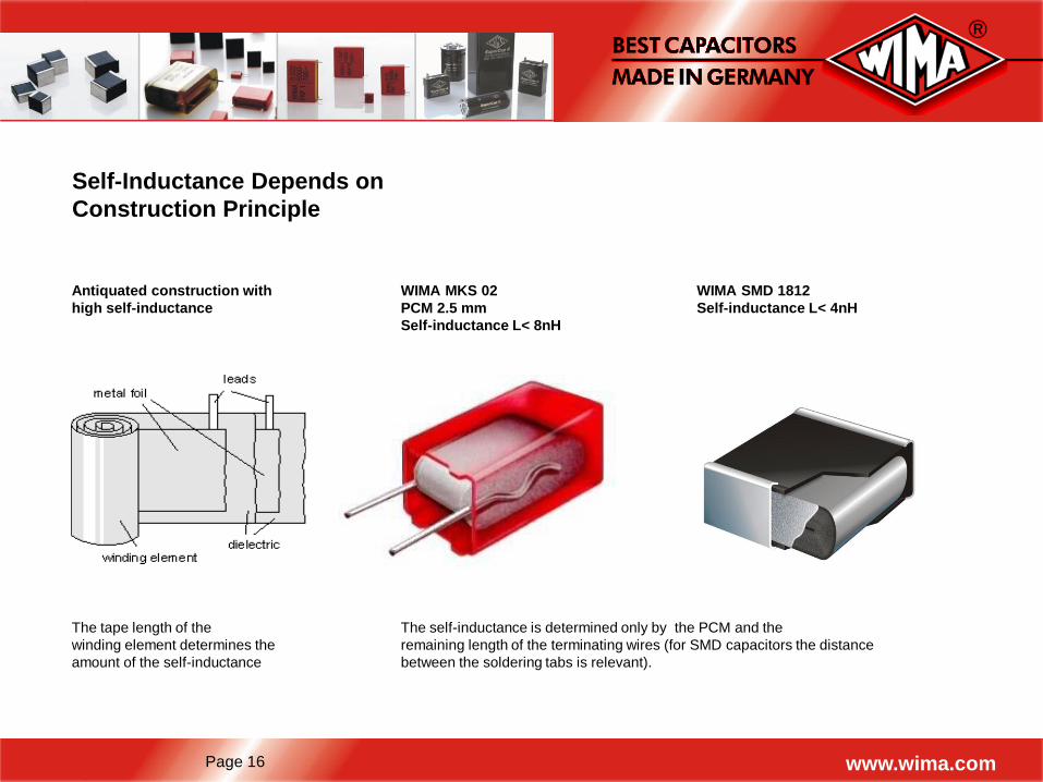
Self-Inductance Depends on
Construction Principle
The tape length of the
winding element determines the
amount of the self-inductance
The self-inductance is determined only by the PCM and the
remaining length of the terminating wires (for SMD capacitors the distance
between the soldering tabs is relevant).
WIMA MKS 02
PCM 2.5 mm
Self-inductance L< 8nH
Antiquated construction with
high self-inductance
WIMA SMD 1812
Self-inductance L< 4nH
Page 17 www.wima.com
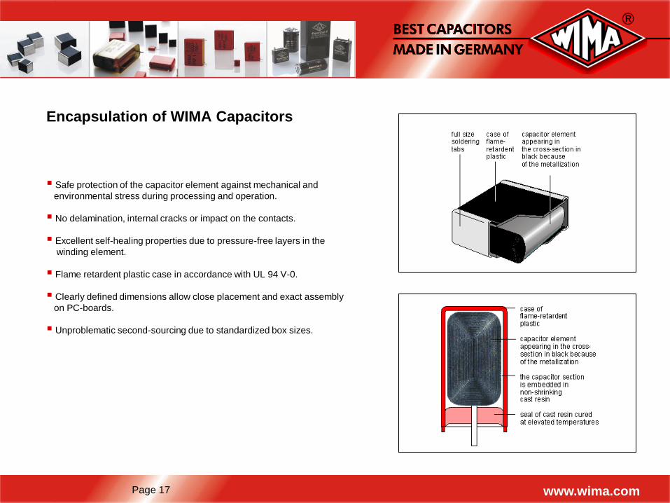
Safe protection of the capacitor element against mechanical and
environmental stress during processing and operation.
No delamination, internal cracks or impact on the contacts.
Excellent self-healing properties due to pressure-free layers in the
winding element.
Flame retardent plastic case in accordance with UL 94 V-0.
Clearly defined dimensions allow close placement and exact assembly
on PC-boards.
Unproblematic second-sourcing due to standardized box sizes.
Encapsulation of WIMA Capacitors
Page 18 www.wima.com
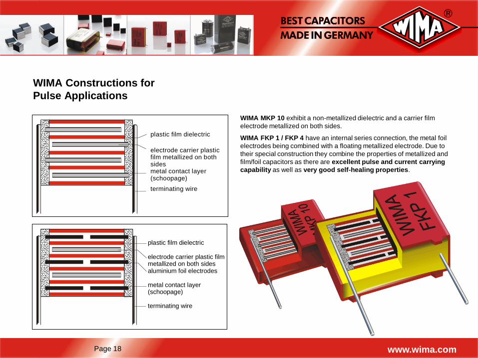
WIMA Constructions for
Pulse Applications
WIMA MKP 10 exhibit a non-metallized dielectric and a carrier film
electrode metallized on both sides.
WIMA FKP 1 / FKP 4 have an internal series connection, the metal foil
electrodes being combined with a floating metallized electrode. Due to
their special construction they combine the properties of metallized and
film/foil capacitors as there are excellent pulse and current carrying
capability as well as very good self-healing properties.
plastic film dielectric
electrode carrier plasticfilm metallized on bothsidesmetal contact layer (schoopage)
terminating wire
plastic film dielectric
electrode carrier plastic filmmetallized on both sidesaluminium foil electrodes
metal contact layer(schoopage)
terminating wire
Page 19 www.wima.com
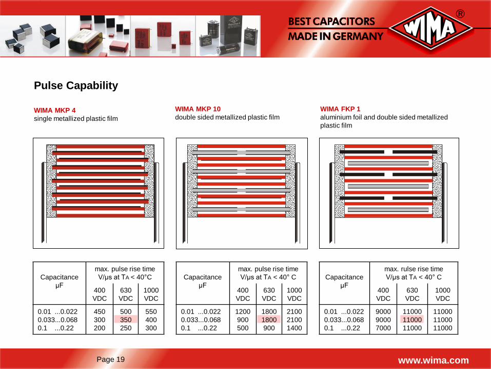
Pulse Capability
WIMA MKP 4
single metallized plastic film
WIMA MKP 10
double sided metallized plastic film
Capacitance
µF
max. pulse rise time
V/µs at TA < 40°C
400
VDC
630
VDC
1000
VDC
0.01 ...0.022
0.033...0.068
0.1 ...0.22
450
300
200
500
350
250
550
400
300
WIMA FKP 1
aluminium foil and double sided metallized
plastic film
Capacitance
µF
max. pulse rise time
V/µs at TA < 40° C
400
VDC
630
VDC
1000
VDC
0.01 ...0.022
0.033...0.068
0.1 ...0.22
1200
900
500
1800
1800
900
2100
2100
1400
Capacitance
µF
max. rulse rise time
V/µs at TA < 40° C
400
VDC
630
VDC
1000
VDC
0.01 ...0.022
0.033...0.068
0.1 ...0.22
9000
9000
7000
11000
11000
11000
11000
11000
11000
Page 20 www.wima.com
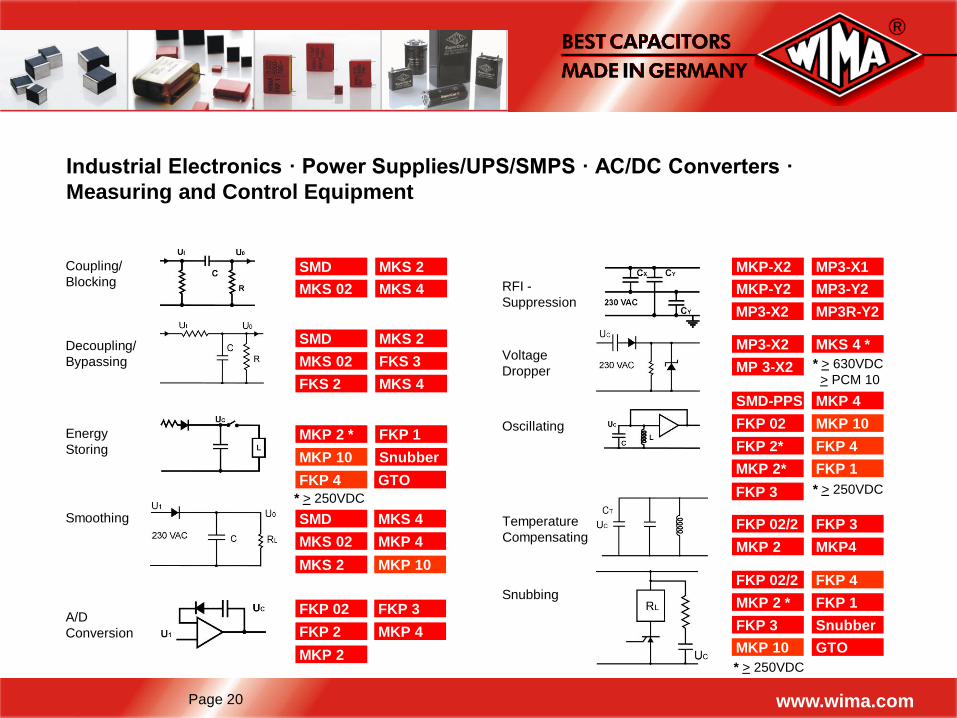
Industrial Electronics · Power Supplies/UPS/SMPS · AC/DC Converters ·
Measuring and Control Equipment
Coupling/
Blocking SMD
MKS 02
MKS 2
MKS 4
Decoupling/
Bypassing
SMD
MKS 02
MKS 2
FKS 3
FKS 2 MKS 4
Smoothing SMD
MKS 02 MKP 4
MKS 4
MKS 2 MKP 10
Energy
Storing MKP 2 *
MKP 10 Snubber
FKP 1
* > 250VDC
A/D
Conversion
FKP 02
FKP 2
FKP 3
MKP 4
Oscillating
SMD-PPS
FKP 02
MKP 4
MKP 10
FKP 2* FKP 4
Snubbing FKP 02/2
MKP 2 *
FKP 4
FKP 1
FKP 3 Snubber
* > 250VDC
RFI -
Suppression
MKP-X2
MKP-Y2
MP3-X1
MP3-Y2
* > 630VDC
> PCM 10
Voltage
Dropper
MP3-X2
MP 3-X2
MKS 4 *
FKP 02/2
MKP 2
FKP 3
MKP4
Temperature
Compensating
* > 250VDC
MKP 10
MP3-X2 MP3R-Y2
FKP 4 GTO
MKP 2
MKP 2* FKP 1
FKP 3
GTO
Page 21 www.wima.com
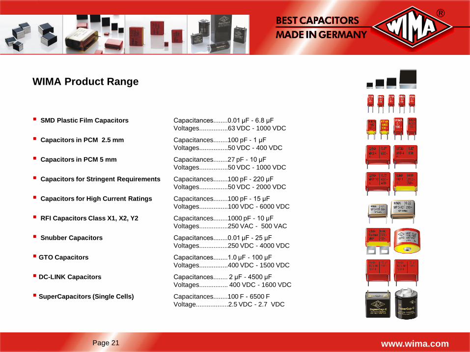
WIMA Product Range
SMD Plastic Film Capacitors Capacitances........0.01 µF - 6.8 µF
Voltages................63 VDC - 1000 VDC
Capacitors in PCM 2.5 mm Capacitances........100 pF - 1 µF
Voltages................50 VDC - 400 VDC
Capacitors in PCM 5 mm Capacitances........27 pF - 10 µF
Voltages................50 VDC - 1000 VDC
Capacitors for Stringent Requirements Capacitances........100 pF - 220 µF
Voltages................50 VDC - 2000 VDC
Capacitors for High Current Ratings Capacitances........100 pF - 15 µF
Voltages................100 VDC - 6000 VDC
RFI Capacitors Class X1, X2, Y2 Capacitances........1000 pF - 10 µF
Voltages................250 VAC - 500 VAC
Snubber Capacitors Capacitances........0.01 µF - 25 µF
Voltages................250 VDC - 4000 VDC
GTO Capacitors Capacitances........1.0 µF - 100 µF
Voltages................400 VDC - 1500 VDC
DC-LINK Capacitors Capacitances........ 2 µF - 4500 µF
Voltages................ 400 VDC - 1600 VDC
SuperCapacitors (Single Cells) Capacitances........100 F - 6500 F
Voltage..................2.5 VDC - 2.7 VDC
Page 22 www.wima.com
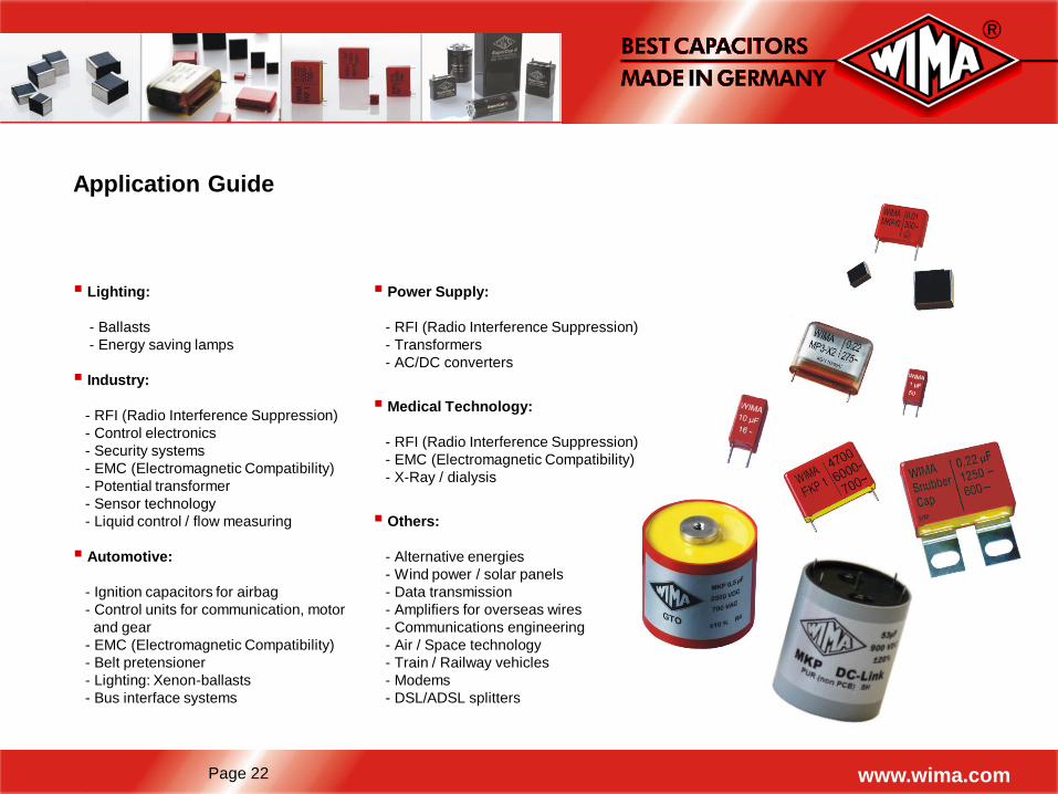
Application Guide
Power Supply:
- RFI (Radio Interference Suppression)
- Transformers
- AC/DC converters
Medical Technology:
- RFI (Radio Interference Suppression)
- EMC (Electromagnetic Compatibility)
- X-Ray / dialysis
Others:
- Alternative energies
- Wind power / solar panels
- Data transmission
- Amplifiers for overseas wires
- Communications engineering
- Air / Space technology
- Train / Railway vehicles
- Modems
- DSL/ADSL splitters
Lighting:
- Ballasts
- Energy saving lamps
Industry:
- RFI (Radio Interference Suppression)
- Control electronics
- Security systems
- EMC (Electromagnetic Compatibility)
- Potential transformer
- Sensor technology
- Liquid control / flow measuring
Automotive:
- Ignition capacitors for airbag
- Control units for communication, motor
and gear
- EMC (Electromagnetic Compatibility)
- Belt pretensioner
- Lighting: Xenon-ballasts
- Bus interface systems
Page 23 www.wima.com
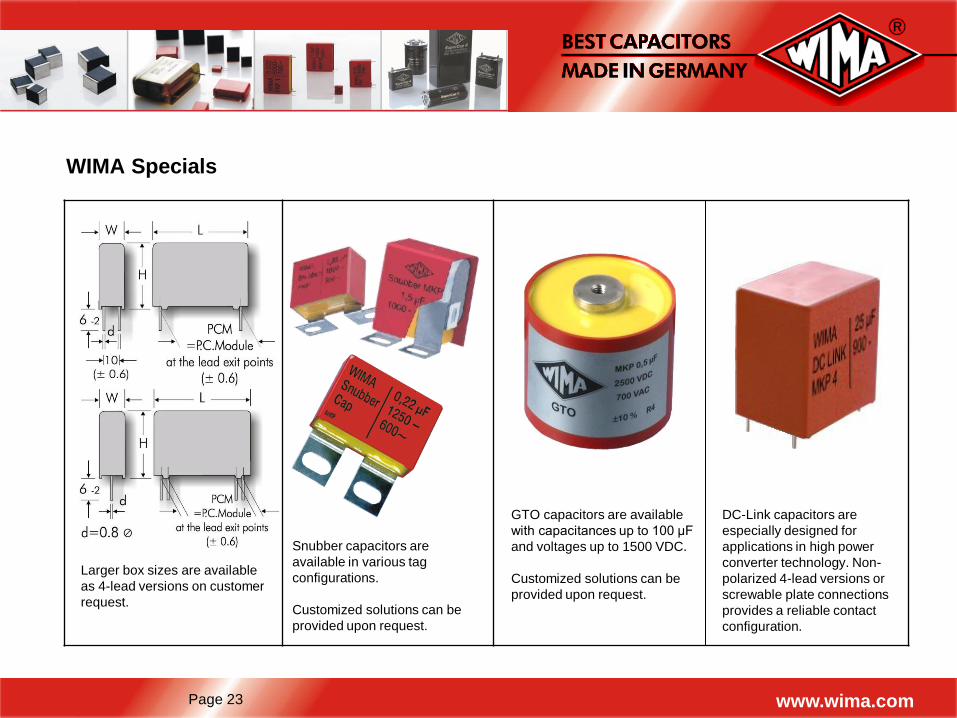
WIMA Specials
Larger box sizes are available
as 4-lead versions on customer
request.
Snubber capacitors are
available in various tag
configurations.
Customized solutions can be
provided upon request.
GTO capacitors are available
with capacitances up to 100 µF
and voltages up to 1500 VDC.
Customized solutions can be
provided upon request.
DC-Link capacitors are
especially designed for
applications in high power
converter technology. Non-
polarized 4-lead versions or
screwable plate connections
provides a reliable contact
configuration.
Page 24 www.wima.com
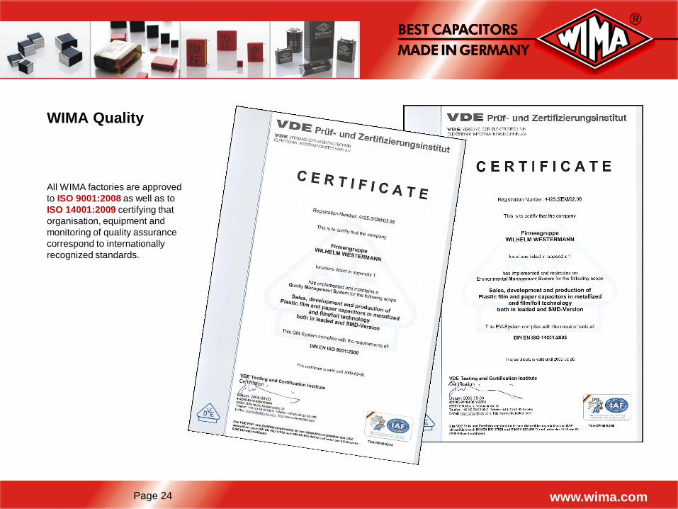
WIMA Quality
All WIMA factories are approved
to ISO 9001:2008 as well as to
ISO 14001:2009 certifying that
organisation, equipment and
monitoring of quality assurance
correspond to internationally
recognized standards.
Page 25 www.wima.com
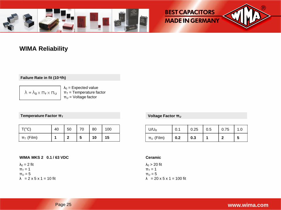
WIMA Reliability
λ0 = Expected value
πT = Temperature factor
πU = Voltage factor
Failure Rate in fit (10-9/h)
Temperature Factor πT
T(°C) 40 50 70 80 100
πT (Film) 1 2 5 10 15
Voltage Factor πU
U/UR 0.1 0.25 0.5 0.75 1.0
πU (Film) 0.2 0.3 1 2 5
WIMA MKS 2 0.1 / 63 VDC
λ0 = 2 fit
πT = 1
πU = 5
λ = 2 x 5 x 1 = 10 fit
Ceramic
λ0 > 20 fit
πT = 1
πU = 5
λ = 20 x 5 x 1 = 100 fit
Page 26 www.wima.com
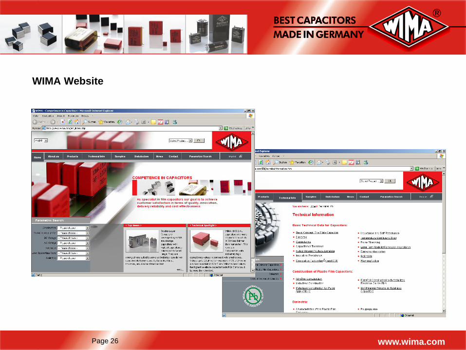
WIMA Website
Page 27 www.wima.com
Thank you!
PT ELECTRONICS
Департамент пассивных компонентов
194214, Санкт-Петербург, пр. Энгельса 71
e-mail: [email protected]
тел. +7 (812) 324-63-50 доб.2332
факс: +7 (812) 324-66-11
www.ptelectronics.ru