Embed Size (px)
Citation preview
WiMax WiMax Applied Radio Network PlanningApplied Radio Network Planning
Course ObjectivesCourse Objectives
At the end of this course you’ll be able to:
• Understand the concept of WIMAX
• Understand the basics of standards related to WIMAX
• Study propagation conditions in WIMAX applications
• Understand some cell planning conditions
• Estimate traffic capacity
• Planning considerations
• Use some Optimization recommendations
• Review new standard for WIMAX Mobile
Course StructureCourse Structure
Day 1 (AM)
• Introduction and Overview
• WiMax Forum
• Physical and MAC Layers
Day 1 (PM)
• Propagation Environments
• Cell Planning
Course StructureCourse Structure
Day 2 (AM)
• Link Budget
• Capacity Planning
• Optimization Process
Day 2 (PM)
• WiMax Mobile
• Course Evaluation and
Feedback
1- Introduction and Overview1- Introduction and Overview
Section 1 – Introduction and Overview
Section 1 – Introduction and Overview
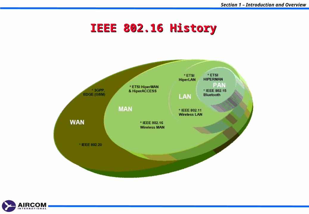
IEEE 802.16 HistoryIEEE 802.16 History
Section 1 – Introduction and Overview
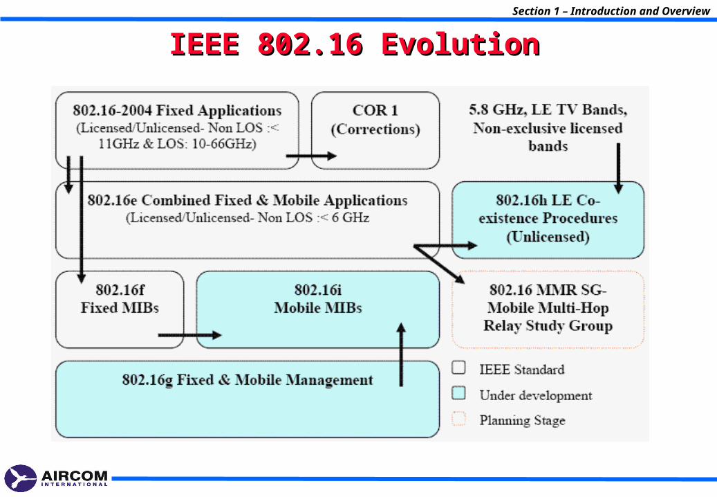
IEEE 802.16 EvolutionIEEE 802.16 Evolution
Section 1 – Introduction and Overview
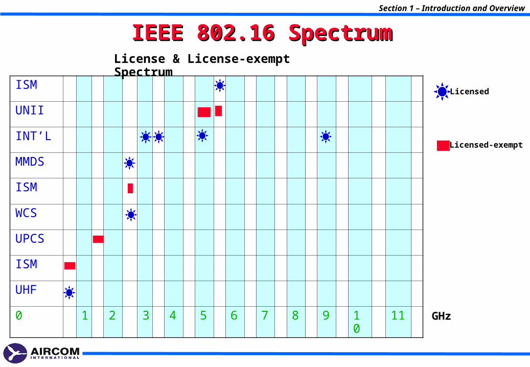
IEEE 802.16 SpectrumIEEE 802.16 Spectrum
ISM
UNII
INT’L
MMDS
ISM
WCS
UPCS
ISM
UHF
0 1 2 3 4 5 6 7 8 9 10 11
Licensed
Licensed-exempt
GHz
License & License-exempt Spectrum
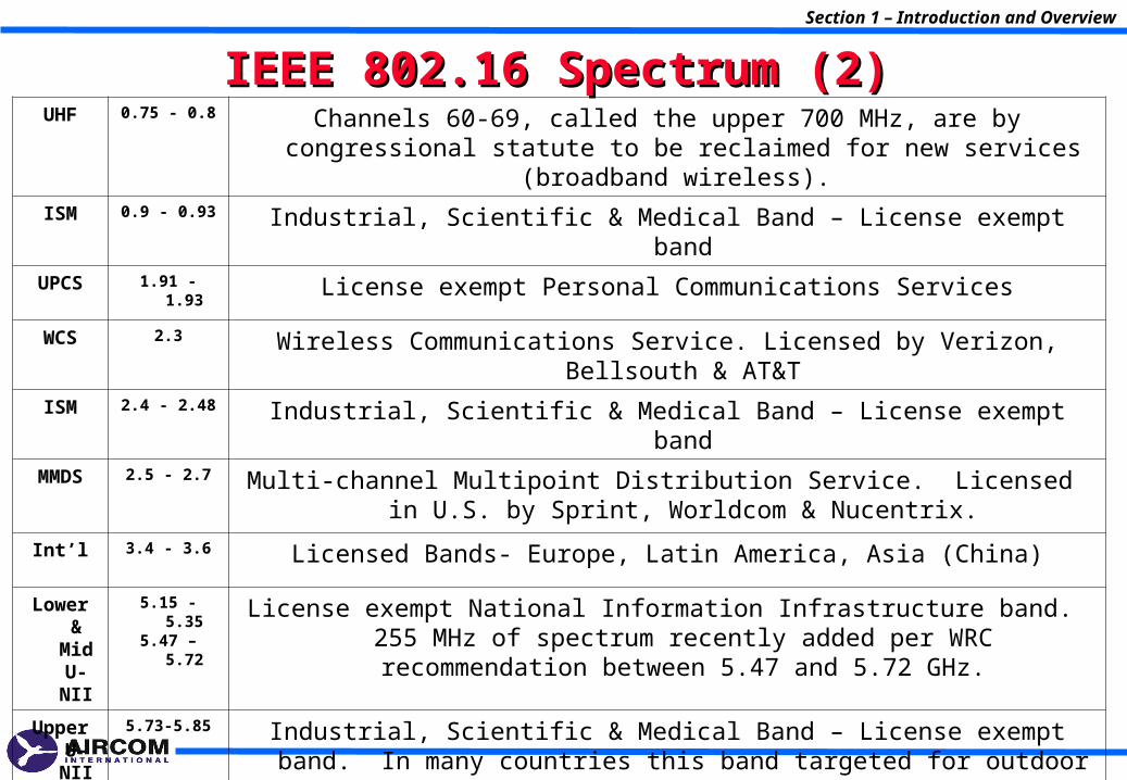
IEEE 802.16 Spectrum (2)IEEE 802.16 Spectrum (2)UHF 0.75 - 0.8 Channels 60-69, called the upper 700 MHz, are by congressional statute to be
reclaimed for new services (broadband wireless).
ISM 0.9 - 0.93 Industrial, Scientific & Medical Band – License exempt band
UPCS 1.91 - 1.93 License exempt Personal Communications Services
WCS 2.3 Wireless Communications Service. Licensed by Verizon, Bellsouth & AT&T
ISM 2.4 - 2.48 Industrial, Scientific & Medical Band – License exempt band
MMDS 2.5 - 2.7 Multi-channel Multipoint Distribution Service. Licensed in U.S. by Sprint, Worldcom & Nucentrix.
Int’l 3.4 - 3.6 Licensed Bands- Europe, Latin America, Asia (China)
Lower & Mid U-NII
5.15 - 5.355.47 – 5.72
License exempt National Information Infrastructure band. 255 MHz of spectrum recently added per WRC recommendation between 5.47 and 5.72 GHz.
Upper U-NII +
ISM
5.73-5.85 Industrial, Scientific & Medical Band – License exempt band. In many countries this band targeted for outdoor applications and allows for higher EIRP (4W vs 1W)
Section 1 – Introduction and Overview
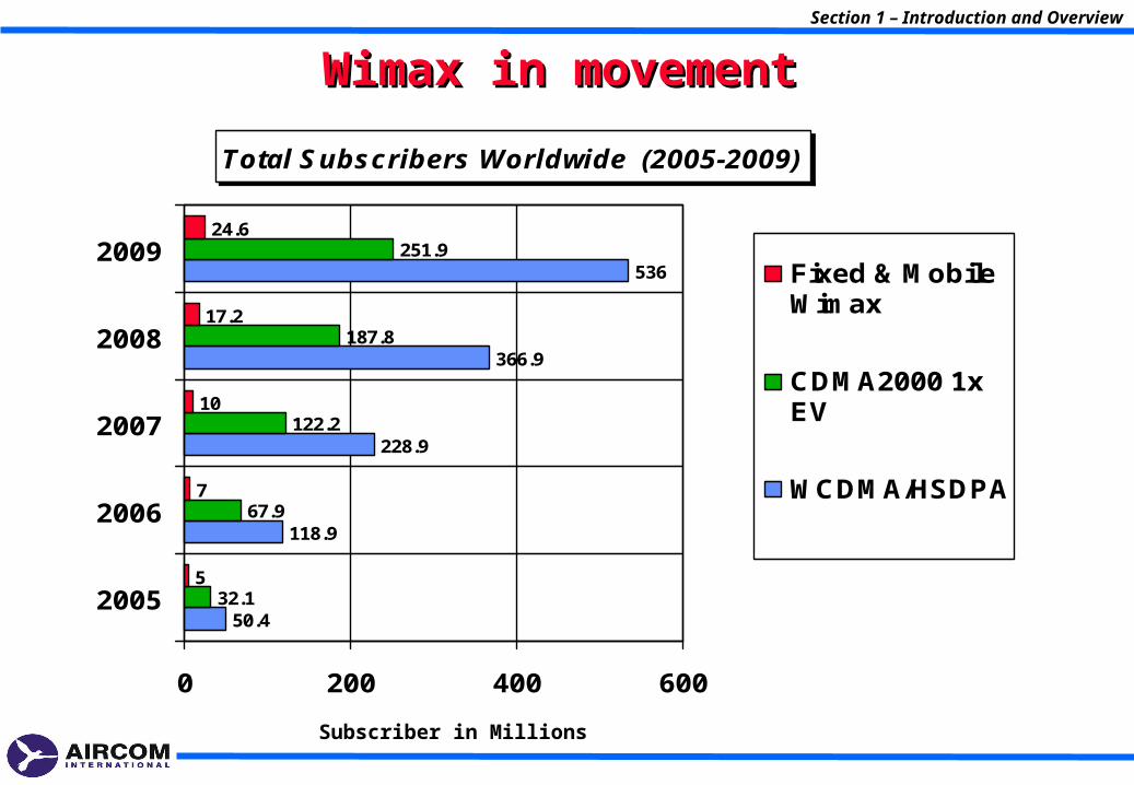
Wimax in movementWimax in movementSection 1 – Introduction and Overview
Total Subscribers Worldwide (2005-2009)
50.4
118.9
228.9
366.9
32.1
67.9
122.2
187.8
251.9
5
7
10
17.2
24.6
536
0 200 400 600
2005
2006
2007
2008
2009Fixed & MobileWimax
CDMA2000 1xEV
WCDMA/HSDPA
Subscriber in Millions
2- WiMax Forum2- WiMax Forum
Section 2 – WiMax Forum
Section 2 – WiMax Forum
What is WiMax Forum?What is WiMax Forum?
Section 2 – WiMax Forum
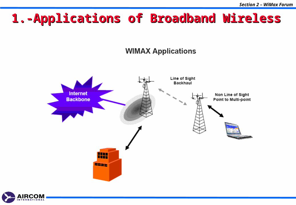
1.-Applications of Broadband Wireless1.-Applications of Broadband Wireless
Section 2 – WiMax Forum
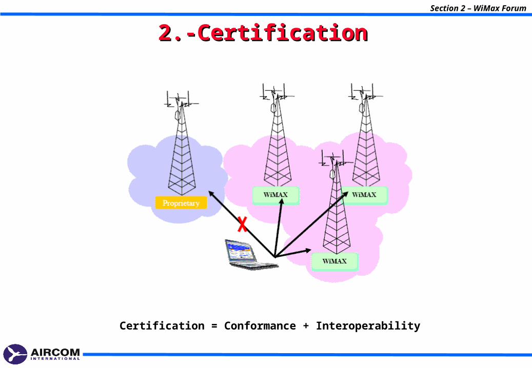
2.-Certification2.-Certification
Certification = Conformance + Interoperability
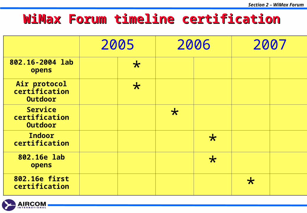
WiMax Forum timeline certificationWiMax Forum timeline certificationSection 2 – WiMax Forum
2005 2006 2007802.16-2004 lab
opens *Air protocol
certification Outdoor *Service certification
Outdoor *Indoor certification *802.16e lab opens *
802.16e first certification *
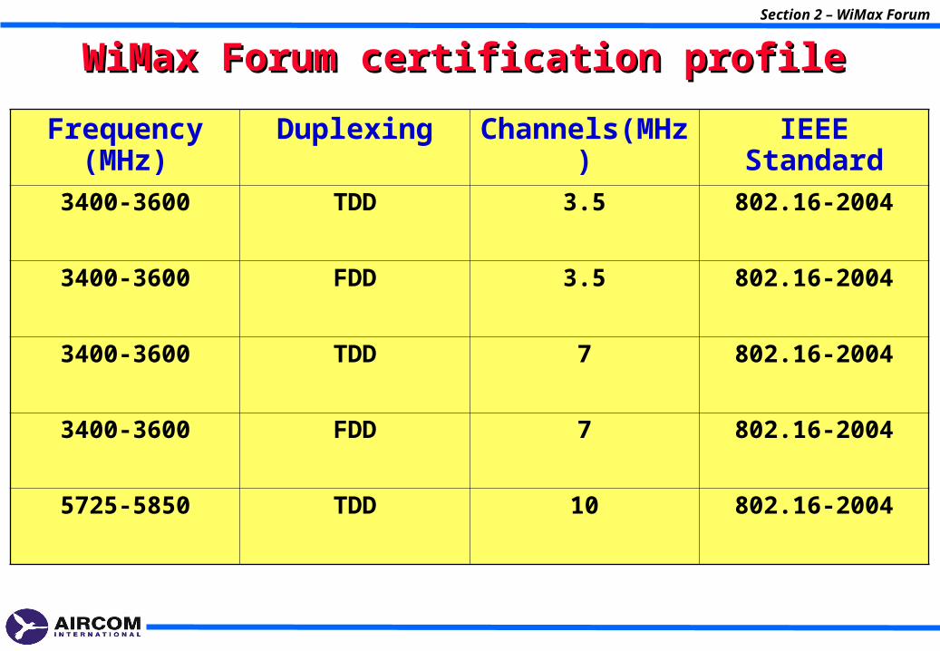
WiMax Forum certification profileWiMax Forum certification profileSection 2 – WiMax Forum
Frequency (MHz)
Duplexing Channels(MHz) IEEE Standard
3400-3600 TDD 3.5 802.16-2004
3400-3600 FDD 3.5 802.16-2004
3400-3600 TDD 7 802.16-2004
3400-3600 FDD 7 802.16-2004
5725-5850 TDD 10 802.16-2004
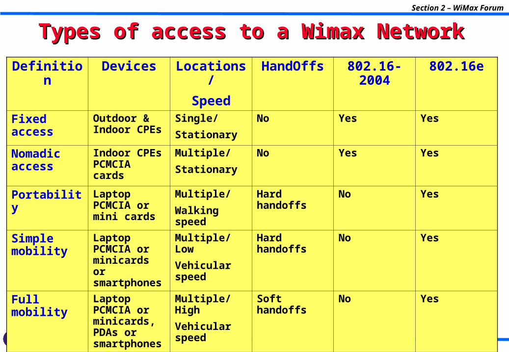
Types of access to a Wimax NetworkTypes of access to a Wimax NetworkSection 2 – WiMax Forum
Definition Devices Locations/
Speed
HandOffs 802.16-2004
802.16e
Fixed access
Outdoor & Indoor CPEs
Single/
Stationary
No Yes Yes
Nomadic access
Indoor CPEs PCMCIA cards
Multiple/
Stationary
No Yes Yes
Portability Laptop PCMCIA or mini cards
Multiple/
Walking speed
Hard handoffs No Yes
Simple mobility
Laptop PCMCIA or minicards or smartphones
Multiple/ Low
Vehicular speed
Hard handoffs No Yes
Full mobility Laptop PCMCIA or minicards, PDAs or smartphones
Multiple/High
Vehicular speed
Soft handoffs No Yes
3- Physical and MAC Layers3- Physical and MAC Layers802.16-2004802.16-2004
Section 3 – Physical and MAC Layers
Section 3 – Physical and MAC Layers
Physical LayerPhysical Layer
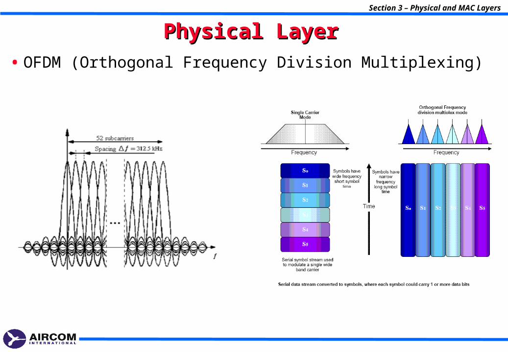
• OFDM (Orthogonal Frequency Division Multiplexing)
OFDM OFDM
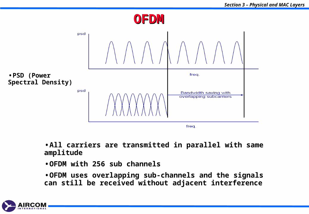
•PSD (Power Spectral Density)
•All carriers are transmitted in parallel with same amplitude
•OFDM with 256 sub channels
•OFDM uses overlapping sub-channels and the signals can still be received without adjacent interference
Section 3 – Physical and MAC Layers
Section 3 – Physical and MAC Layers
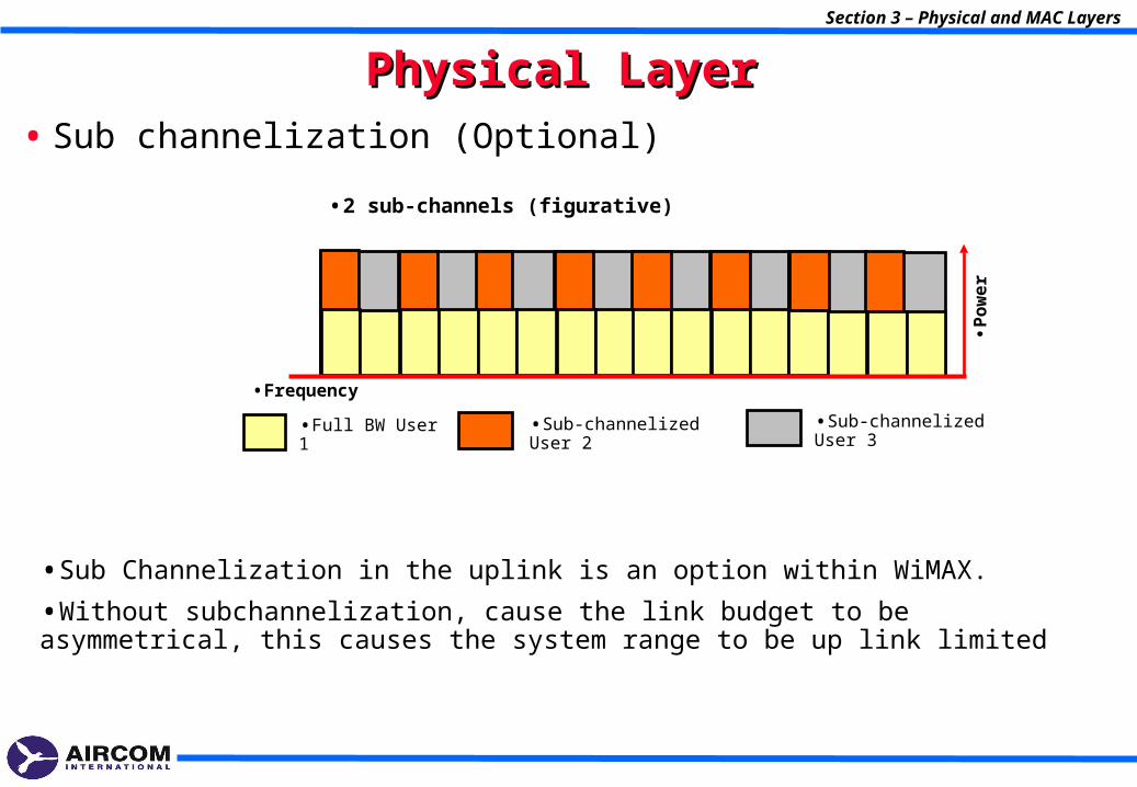
Physical LayerPhysical Layer• Sub channelization (Optional)
•Full BW User 1 •Sub-channelized User 2 •Sub-channelized User 3
•2 sub-channels (figurative)
•Frequency
•Po
we
r
•Sub Channelization in the uplink is an option within WiMAX.
•Without subchannelization, cause the link budget to be asymmetrical, this causes the system range to be up link limited
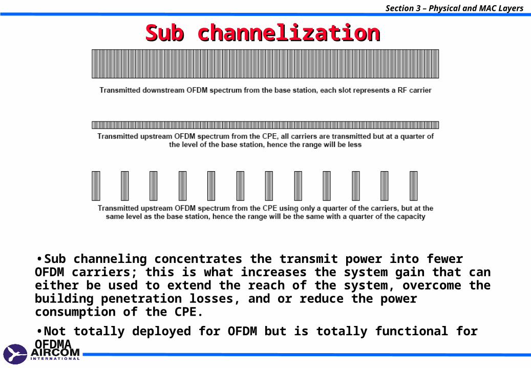
Sub channelizationSub channelization
•Sub channeling concentrates the transmit power into fewer OFDM carriers; this is what increases the system gain that can either be used to extend the reach of the system, overcome the building penetration losses, and or reduce the power consumption of the CPE.
•Not totally deployed for OFDM but is totally functional for OFDMA
Section 3 – Physical and MAC Layers
Section 3 – Physical and MAC Layers
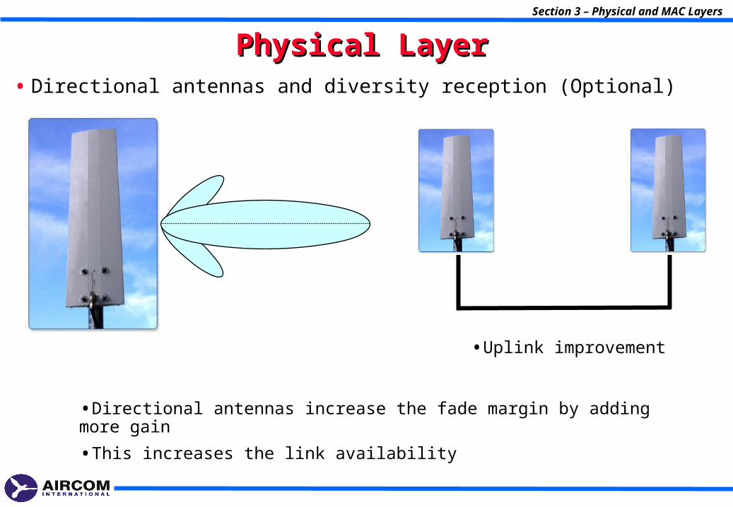
Physical LayerPhysical Layer• Directional antennas and diversity reception (Optional)
•Uplink improvement
•Directional antennas increase the fade margin by adding more gain
•This increases the link availability
Physical LayerPhysical Layer
• AAS (Adaptive Antennas System)
Section 3 – Physical and MAC Layers
•Are an optional part of the 802.16 standard.
•These have beam forming properties that can steer their focus to a particular direction or directions.
•This means that while transmitting, the signal can be limited to the required direction of the receiver; like a spotlight.
•They also have the property of suppressing cochannel interference from other locations.
Section 3 – Physical and MAC Layers
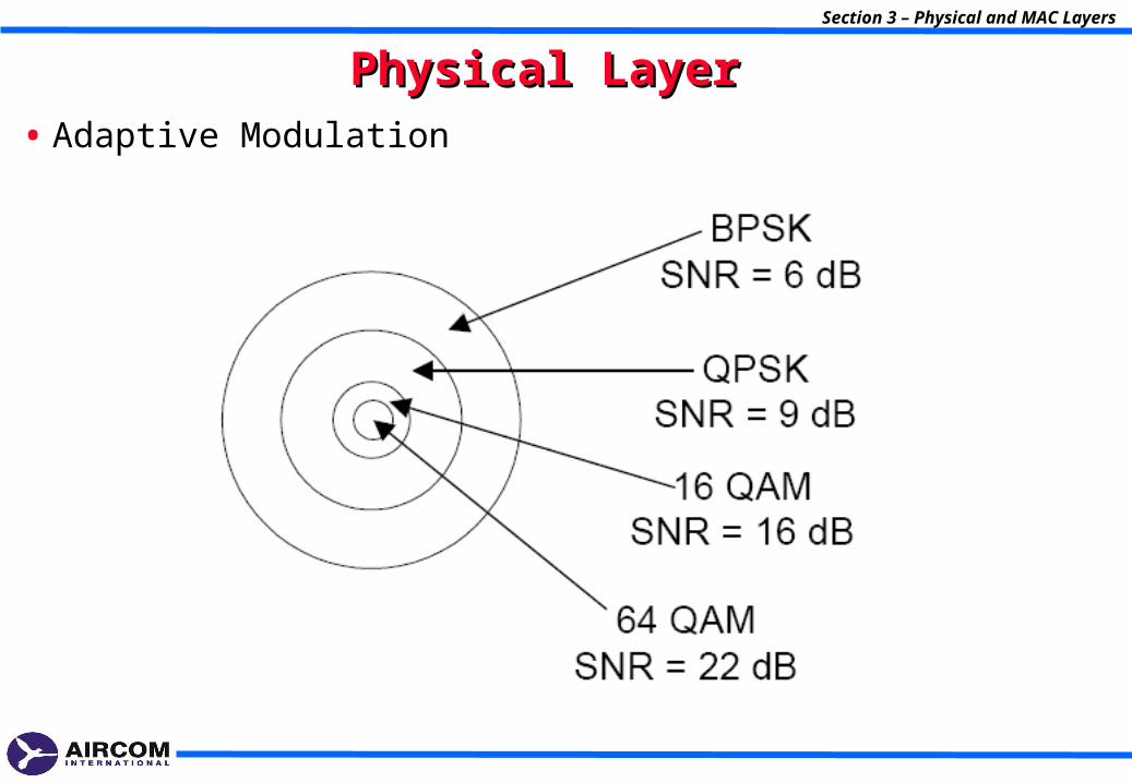
Physical Layer Physical Layer • Adaptive Modulation

Physical LayerPhysical Layer
• Power Control (PC)
•Power control algorithms are used to improve the overall performance of the system, it is implemented by the base station sending power control information to each of the CPEs to regulate the transmit power level so that the level received at the base station is at a pre-determined level
•In a dynamical changing fading environment this pre-determined performance level means that the CPE only transmits enough power to meet this requirement
•Are an optional part of the 802.16 standard.
•For LOS the transmit power of the CPE is approximately proportional to it’s distance from the base station, for NLOS it is also heavily dependant on the clearance and obstructions.
Section 3 – Physical and MAC Layers
MAC LayerMAC Layer
• Protocol point-multi-point
• Terminal could be shared among many end-user equipment (phones and pc’s)
• QoS defined for each service
• GoS and traffic parameters
• Downlink is multiplex with TDM
• Uplink is shared with TDMA
• 802.16 is connection oriented
MAC LayerMAC Layer
• Upon entering the network, three management connections are established, in both directions. Every connection is used for different QoS connection type:
1. Basic connection – used to transfer of short, time critical MAC and RLC messages
2. Secondary management Connection – used for transfer of standard-based protocols such as DHCP,TFTP,SNMP
3. - Other types of connection, like connection reserved for broadcasting
Section 3 – Physical and MAC Layers
4- Propagation Environments4- Propagation Environments
Section 4 – Propagation Environments
Section 4 – Propagation Environments
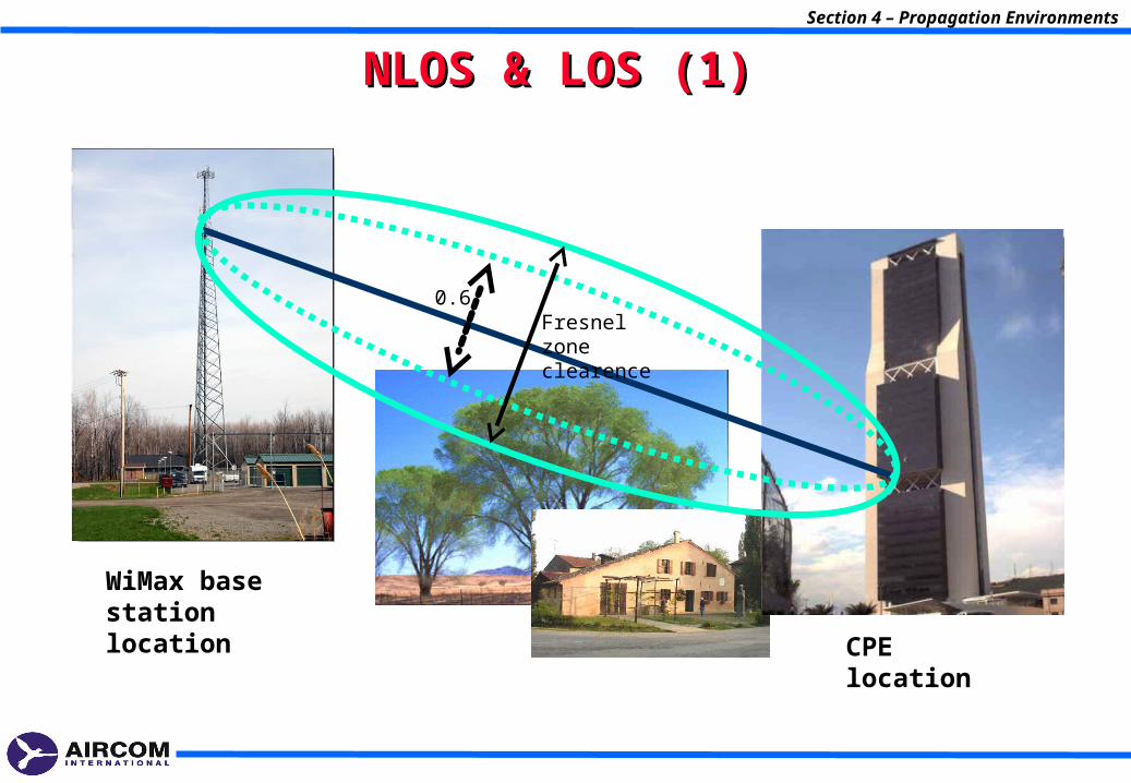
NLOS & LOS (1)NLOS & LOS (1)
CPE location
WiMax base station location
Fresnel zone clearence
0.6
Section 4 – Propagation Environments
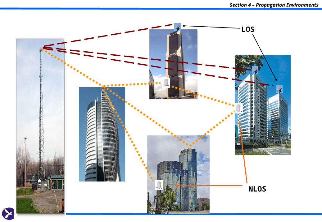
NLOS
LOS
Section 4 – Propagation Environments
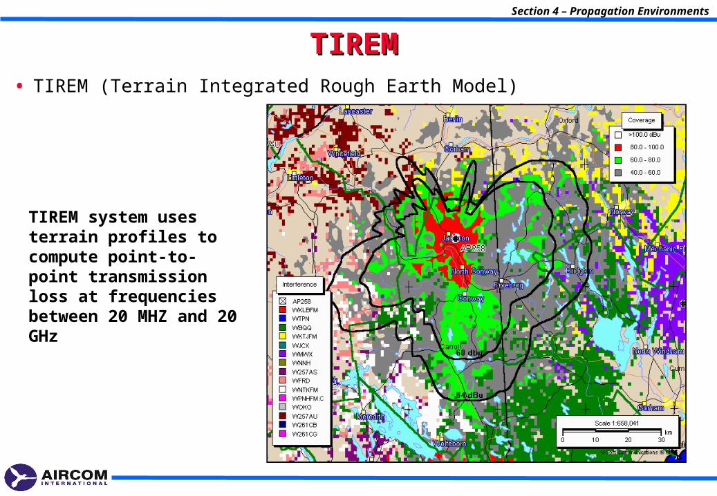
TIREMTIREM• TIREM (Terrain Integrated Rough Earth Model)
TIREM system uses terrain profiles to compute point-to-point transmission loss at frequencies between 20 MHZ and 20 GHz
Section 4 – Propagation Environments
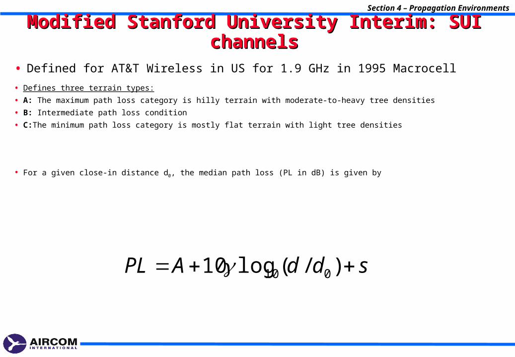
Modified Stanford University Interim: SUI channelsModified Stanford University Interim: SUI channels
• Defines three terrain types:
• A: The maximum path loss category is hilly terrain with moderate-to-heavy tree densities
• B: Intermediate path loss condition
• C:The minimum path loss category is mostly flat terrain with light tree densities
• For a given close-in distance d0, the median path loss (PL in dB) is given by
• Defined for AT&T Wireless in US for 1.9 GHz in 1995 Macrocell
sddAPL )/(log10 010
Section 4 – Propagation Environments
Modified Stanford University Interim: SUI channelsModified Stanford University Interim: SUI channels
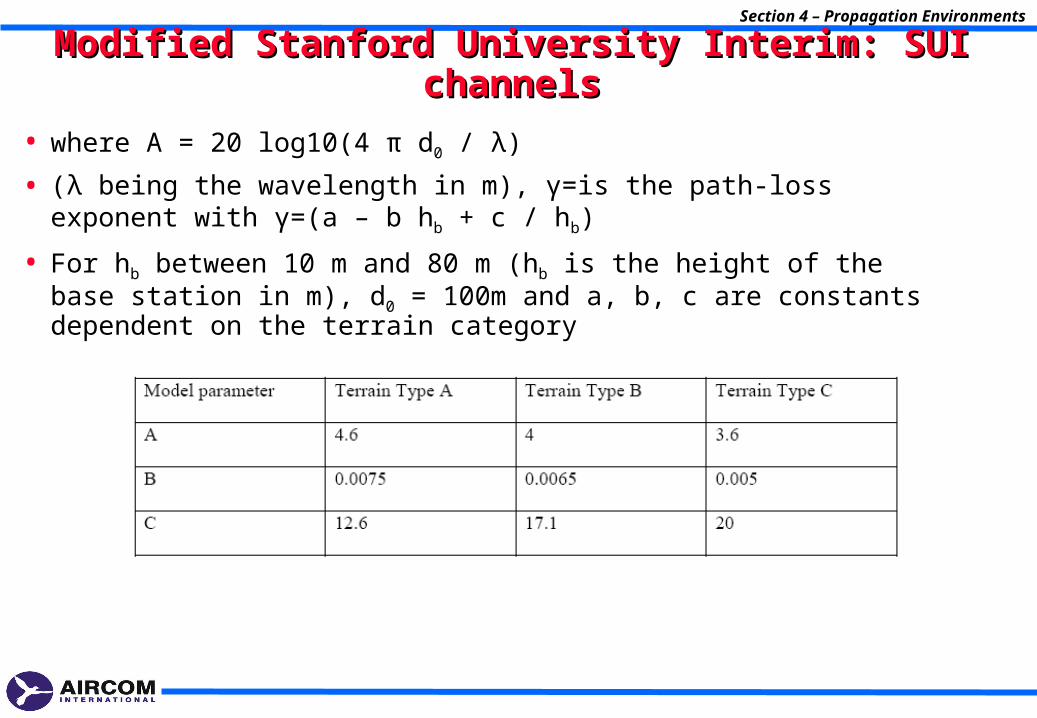
• where A = 20 log10(4 π d0 / λ)
• (λ being the wavelength in m), γ=is the path-loss exponent with γ=(a – b hb + c / hb)
• For hb between 10 m and 80 m (hb is the height of the base station in m), d0 = 100m and a, b, c are constants dependent on the terrain category
Section 4 – Propagation Environments
Modified Stanford University Interim: SUI channelsModified Stanford University Interim: SUI channels
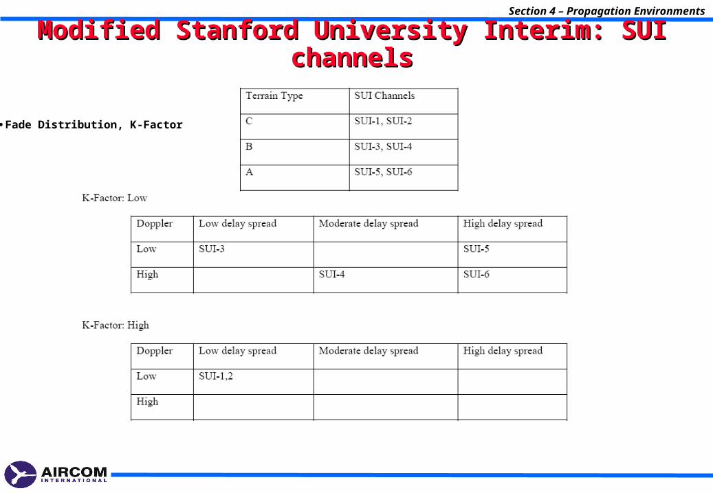
•Fade Distribution, K-Factor
Section 4 – Propagation Environments
Modified Stanford University Interim: SUI channelsModified Stanford University Interim: SUI channels
•Although the SUI model proposes different sets of parameters for three types of environments, the categories are not specified in a particularly systematic manner and do not explicitly include urban and suburban environments.

5- Cell Planning5- Cell Planning
Section 5 – Cell Planning
Section 5 – Cell Planning
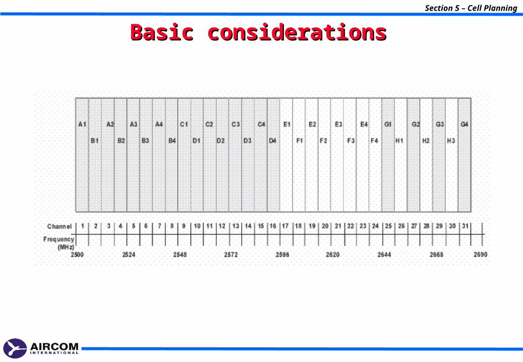
Basic considerationsBasic considerations
Section 5 – Cell Planning
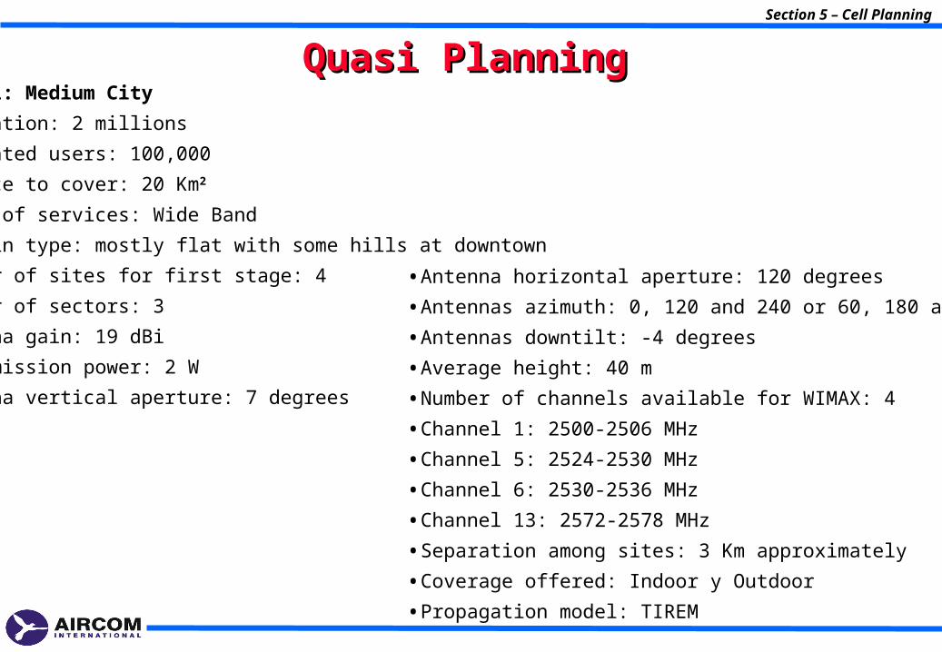
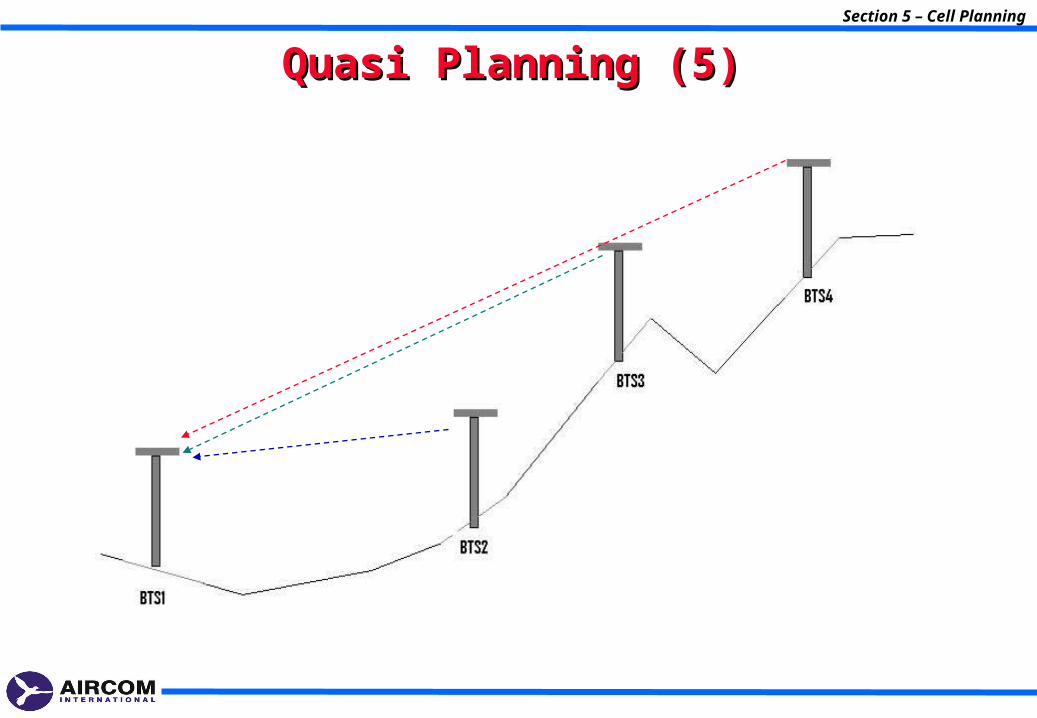
Quasi PlanningQuasi Planning•Case 1: Medium City
•Population: 2 millions
•Estimated users: 100,000
•Surface to cover: 20 Km2
•Types of services: Wide Band
•Terrain type: mostly flat with some hills at downtown
•Number of sites for first stage: 4
•Number of sectors: 3
•Antenna gain: 19 dBi
•Transmission power: 2 W
•Antenna vertical aperture: 7 degrees
•Antenna horizontal aperture: 120 degrees
•Antennas azimuth: 0, 120 and 240 or 60, 180 and 300
•Antennas downtilt: -4 degrees
•Average height: 40 m
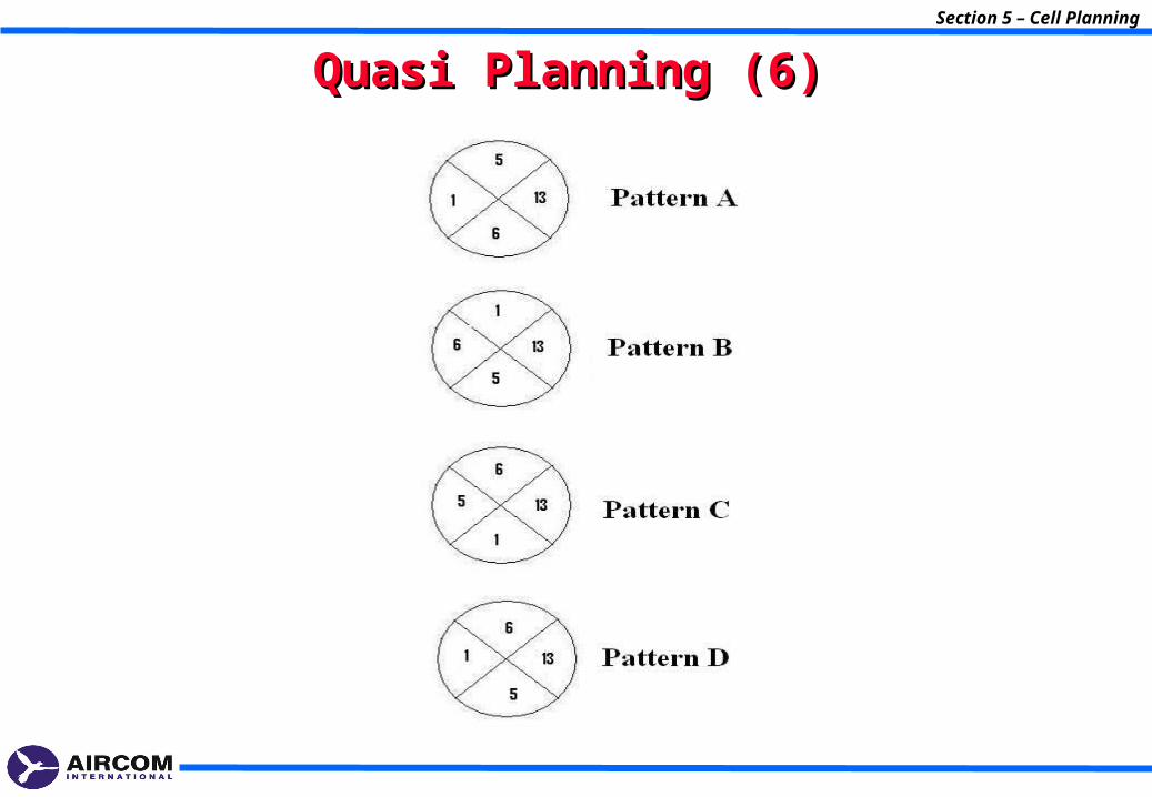
•Number of channels available for WIMAX: 4
•Channel 1: 2500-2506 MHz
•Channel 5: 2524-2530 MHz
•Channel 6: 2530-2536 MHz
•Channel 13: 2572-2578 MHz
•Separation among sites: 3 Km approximately
•Coverage offered: Indoor y Outdoor
•Propagation model: TIREM
Section 5 – Cell Planning
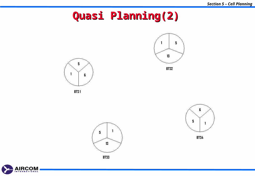
Quasi Planning(2)Quasi Planning(2)
Section 5 – Cell Planning
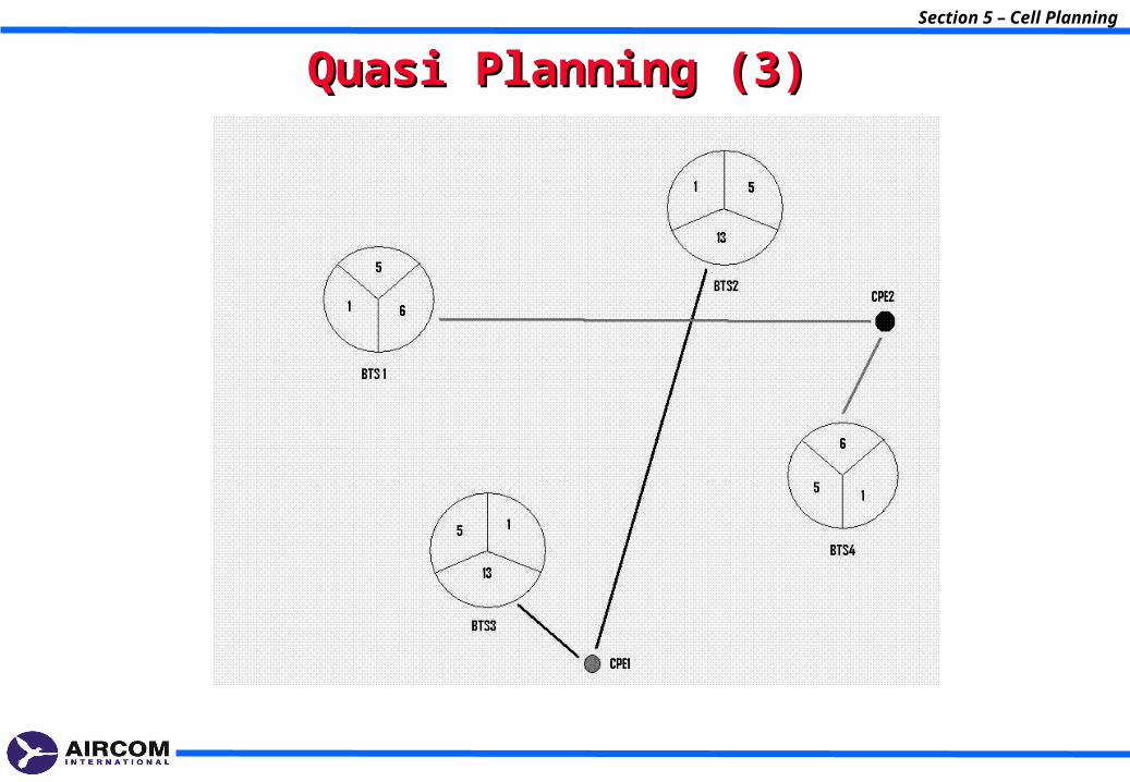
Quasi Planning (3)Quasi Planning (3)
Section 5 – Cell Planning
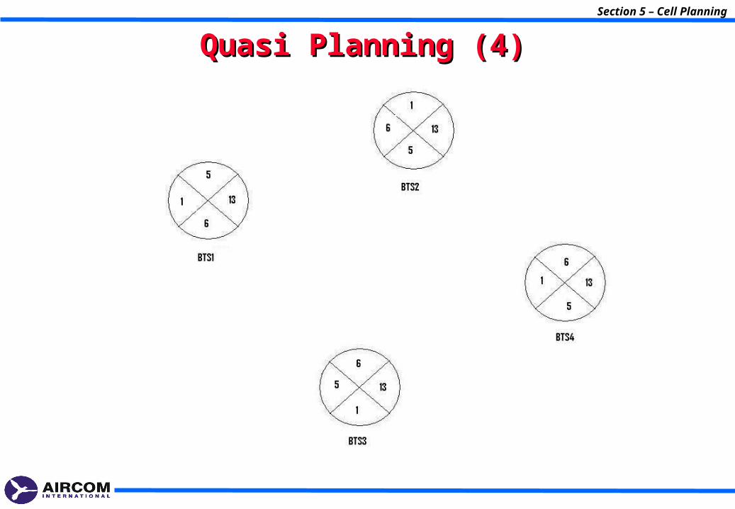
Quasi Planning (4)Quasi Planning (4)
Section 5 – Cell Planning
Quasi Planning (5)Quasi Planning (5)
Section 5 – Cell Planning
Quasi Planning (6)Quasi Planning (6)

6- Link Budget6- Link Budget
Section 6 – Link Budget
Section 6 – Link Budget
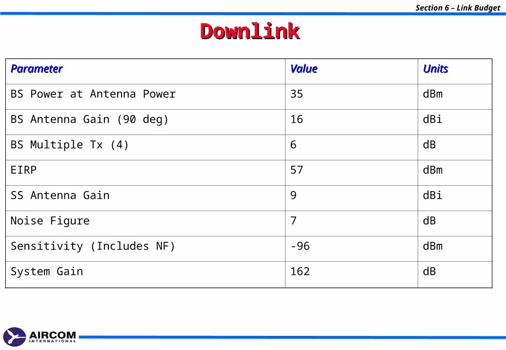
DownlinkDownlink
ParameterParameter ValueValue UnitsUnits
BS Power at Antenna Power 35 dBm
BS Antenna Gain (90 deg) 16 dBi
BS Multiple Tx (4) 6 dB
EIRP 57 dBm
SS Antenna Gain 9 dBi
Noise Figure 7 dB
Sensitivity (Includes NF) -96 dBm
System Gain 162 dB
Section 6 – Link Budget
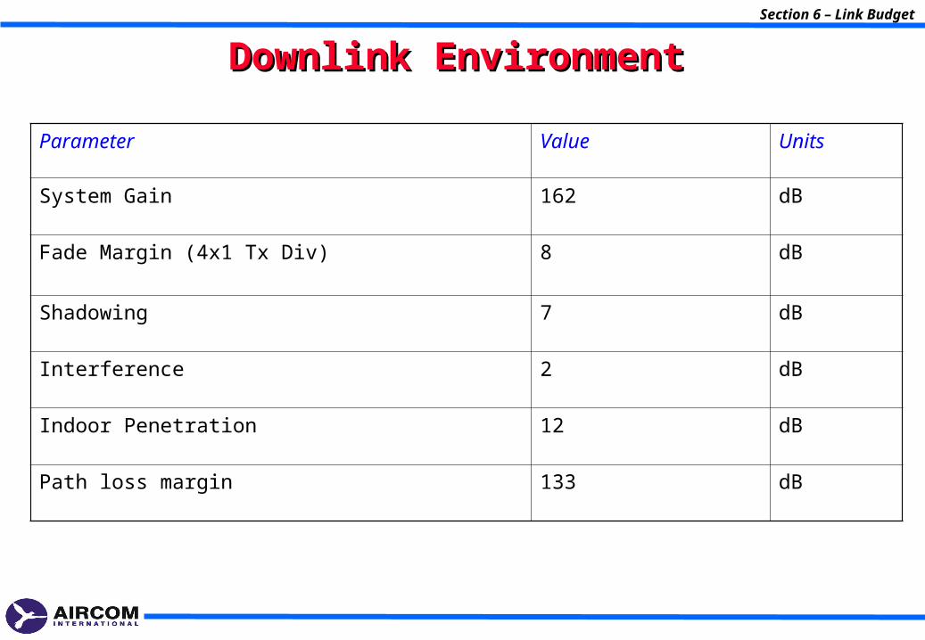
Downlink EnvironmentDownlink Environment
Parameter Value Units
System Gain 162 dB
Fade Margin (4x1 Tx Div) 8 dB
Shadowing 7 dB
Interference 2 dB
Indoor Penetration 12 dB
Path loss margin 133 dB
Section 6 – Link Budget
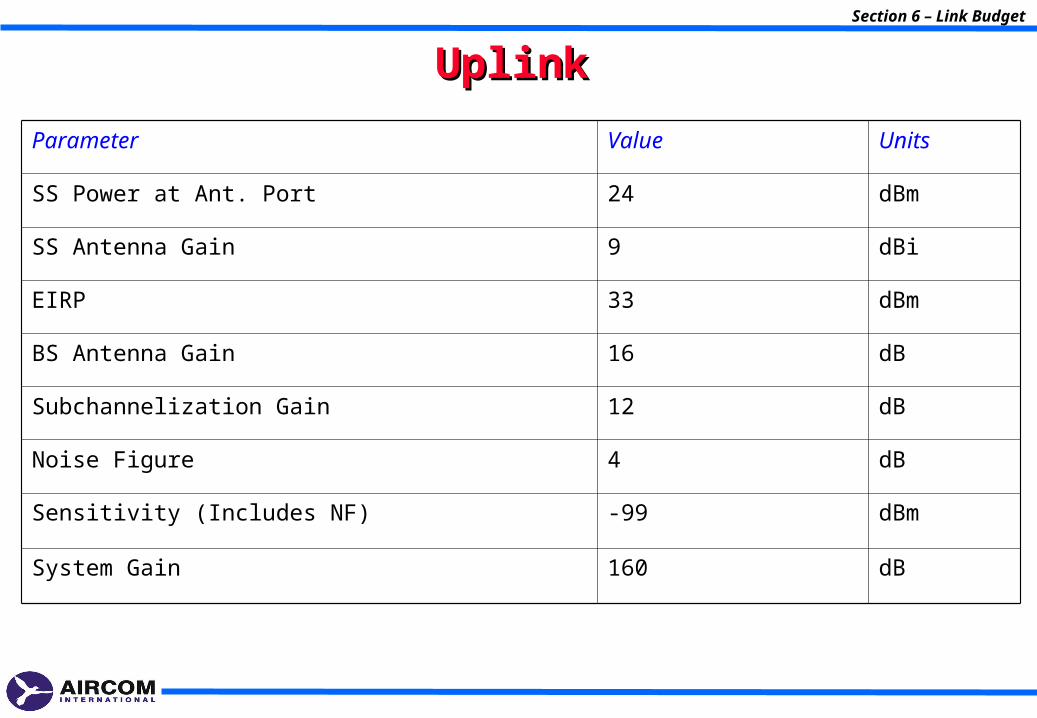
UplinkUplink
Parameter Value Units
SS Power at Ant. Port 24 dBm
SS Antenna Gain 9 dBi
EIRP 33 dBm
BS Antenna Gain 16 dB
Subchannelization Gain 12 dB
Noise Figure 4 dB
Sensitivity (Includes NF) -99 dBm
System Gain 160 dB
Section 6 – Link Budget
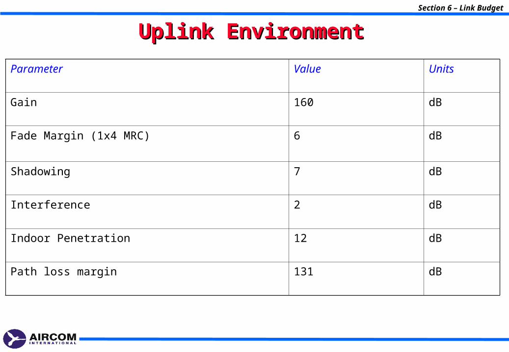
Uplink EnvironmentUplink Environment
Parameter Value Units
Gain 160 dB
Fade Margin (1x4 MRC) 6 dB
Shadowing 7 dB
Interference 2 dB
Indoor Penetration 12 dB
Path loss margin 131 dB
Section 6 – Link Budget
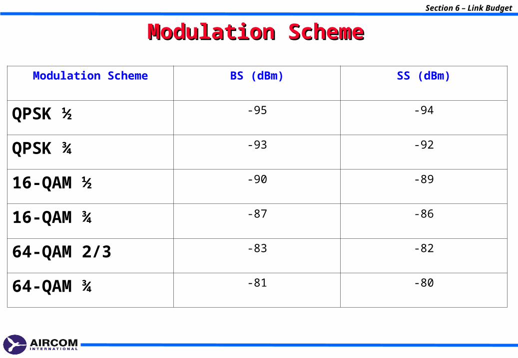
Modulation SchemeModulation Scheme
Modulation Scheme BS (dBm) SS (dBm)
QPSK ½ -95 -94
QPSK ¾ -93 -92
16-QAM ½ -90 -89
16-QAM ¾ -87 -86
64-QAM 2/3 -83 -82
64-QAM ¾ -81 -80
7- Capacity Planning7- Capacity Planning
Section 7 – Capacity Planning
Section 7 – Capacity Planning
TDDTDD
•TDD is supporting:
•How the base station creates data transmission frames. A frame is the basic unit of data communication. It allows data traffic to travel uplink and downlink over the same channel, without “colliding”.
•How subscribers’ CPEs contend for uplink transmission times (time slots) defined in the frame. After the CPE obtains access to a time slot, the CPE’s data can be transmitted upstream to the base station.
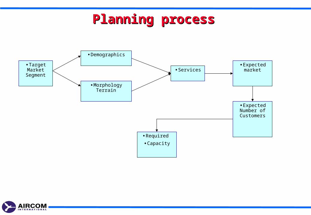
Planning processPlanning process
•Target Market
Segment
•Demographics
•Services•Expected
market
•Morphology Terrain
•Expected Number of Customers
•Required
•Capacity
Section 7 – Capacity Planning
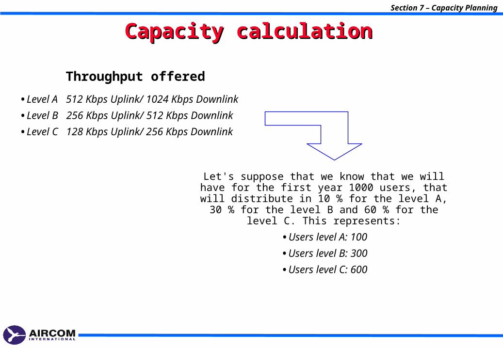
Capacity calculationCapacity calculation
•Level A 512 Kbps Uplink/ 1024 Kbps Downlink
•Level B 256 Kbps Uplink/ 512 Kbps Downlink
•Level C 128 Kbps Uplink/ 256 Kbps Downlink
Throughput offered
Let's suppose that we know that we will have for the first year 1000 users, that will distribute in 10 % for the level
A, 30 % for the level B and 60 % for the level C. This represents:
•Users level A: 100
•Users level B: 300
•Users level C: 600
Section 7 – Capacity Planning
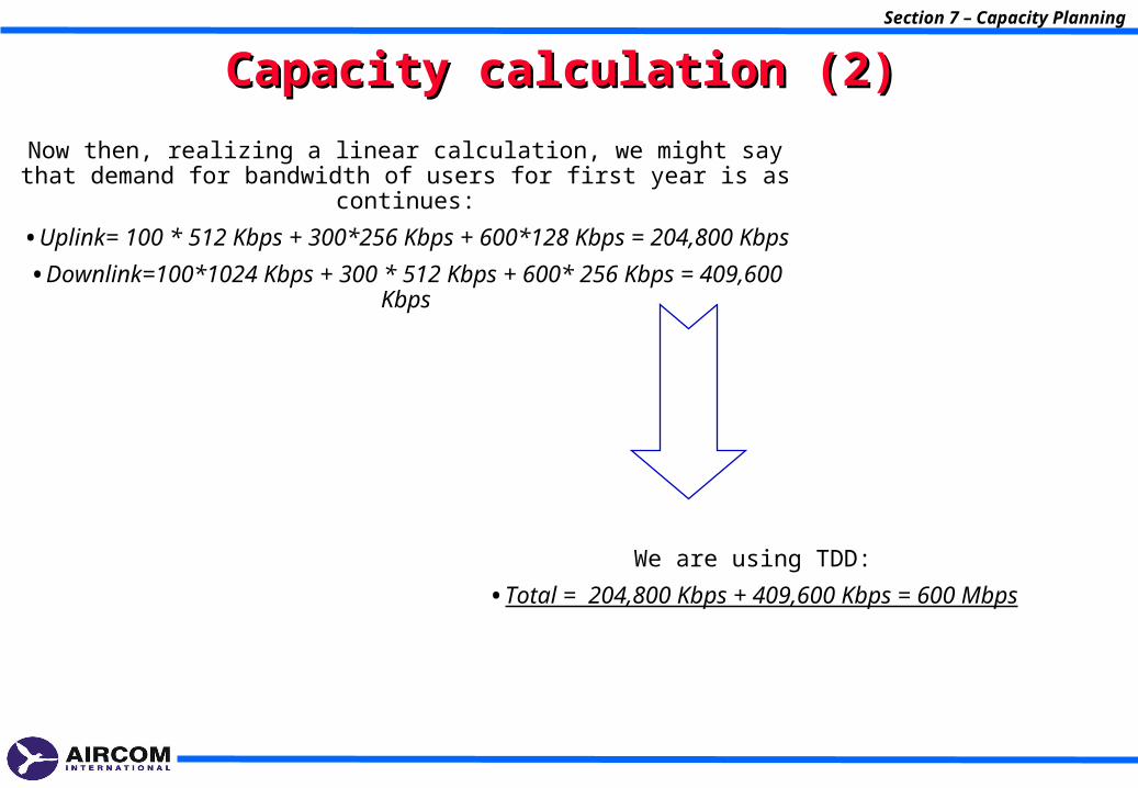
Capacity calculation (2)Capacity calculation (2)
Now then, realizing a linear calculation, we might say that demand for bandwidth of users for first year is as continues:
•Uplink= 100 * 512 Kbps + 300*256 Kbps + 600*128 Kbps = 204,800 Kbps
•Downlink=100*1024 Kbps + 300 * 512 Kbps + 600* 256 Kbps = 409,600 Kbps
We are using TDD:
•Total = 204,800 Kbps + 409,600 Kbps = 600 Mbps
Section 7 – Capacity Planning
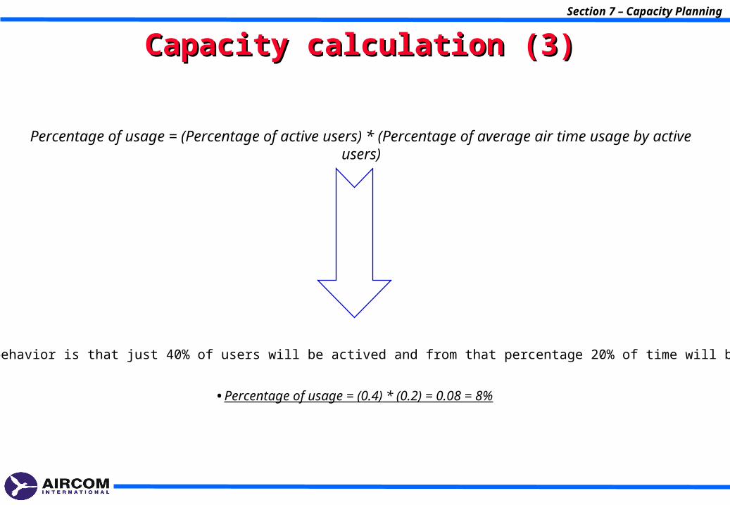
Capacity calculation (3)Capacity calculation (3)
Percentage of usage = (Percentage of active users) * (Percentage of average air time usage by active users)
•If user behavior is that just 40% of users will be actived and from that percentage 20% of time will be used:
•Percentage of usage = (0.4) * (0.2) = 0.08 = 8%
Section 7 – Capacity Planning
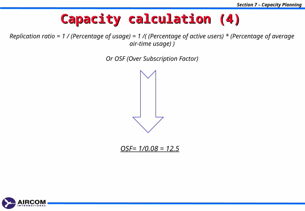
Capacity calculation (4)Capacity calculation (4)Replication ratio = 1 / (Percentage of usage) = 1 /( (Percentage of active users) * (Percentage of
average air-time usage) )
Or OSF (Over Subscription Factor)
OSF= 1/0.08 = 12.5
Section 7 – Capacity Planning
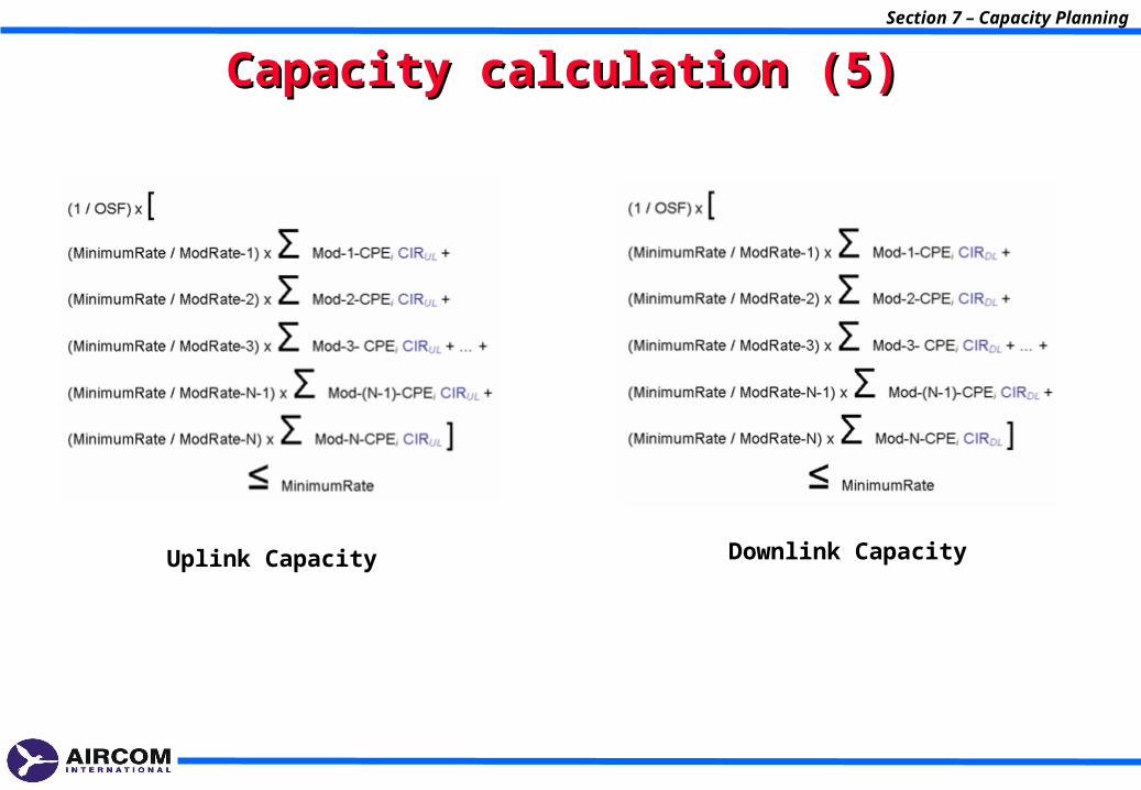
Capacity calculation (5)Capacity calculation (5)
Uplink Capacity Downlink Capacity
8- Optimization Process8- Optimization Process
Section 8 – Optimization Process
Section 8 – Optimization Process
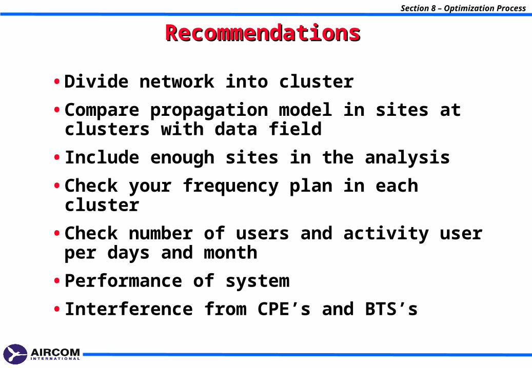
RecommendationsRecommendations
• Divide network into cluster
• Compare propagation model in sites at clusters with data field
• Include enough sites in the analysis
• Check your frequency plan in each cluster
• Check number of users and activity user per days and month
• Performance of system
• Interference from CPE’s and BTS’s
Section 8 – Optimization Process
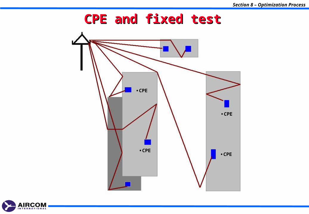
CPE and fixed testCPE and fixed test
•CPE
•CPE•CPE
•CPE
Section 8 – Optimization Process
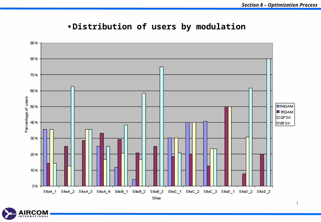
•Distribution of users by modulation
9.- WIMAX Mobile9.- WIMAX Mobile
Section 8 – Optimization Process
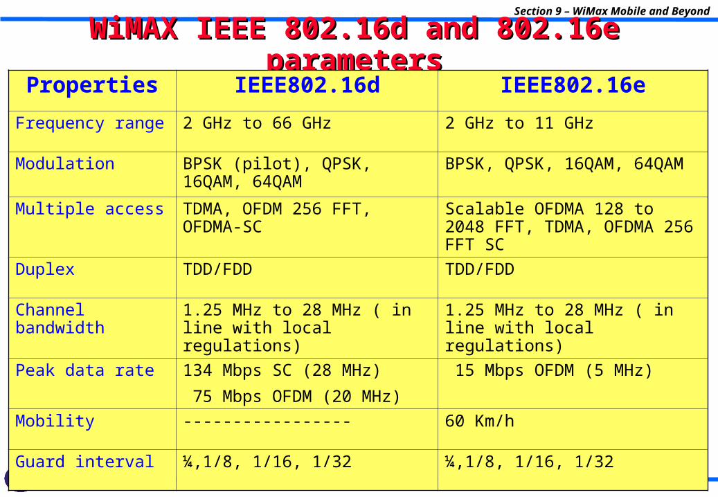
WiMAX IEEE 802.16d and 802.16e parametersWiMAX IEEE 802.16d and 802.16e parametersSection 9 – WiMax Mobile and Beyond
Properties IEEE802.16d IEEE802.16e
Frequency range 2 GHz to 66 GHz 2 GHz to 11 GHz
Modulation BPSK (pilot), QPSK, 16QAM, 64QAM
BPSK, QPSK, 16QAM, 64QAM
Multiple access TDMA, OFDM 256 FFT, OFDMA-SC
Scalable OFDMA 128 to 2048 FFT, TDMA, OFDMA 256 FFT SC
Duplex TDD/FDD TDD/FDD
Channel bandwidth 1.25 MHz to 28 MHz ( in line with local regulations)
1.25 MHz to 28 MHz ( in line with local regulations)
Peak data rate 134 Mbps SC (28 MHz)
75 Mbps OFDM (20 MHz)
15 Mbps OFDM (5 MHz)
Mobility ----------------- 60 Km/h
Guard interval ¼,1/8, 1/16, 1/32 ¼,1/8, 1/16, 1/32
PHY LayerPHY Layer
• Scalable OFDMA
• New frame structure
• Data channels configurations
• Fully used subchannelization (FUSC)
• Partially used subchannelization (PUSC)
• Advanced modulation and coding scheme (AMC)
• Modulation and channel coding
• Smart antennas technologies
Section 9 – WiMax Mobile and Beyond
Section 9 – WiMax Mobile and Beyond
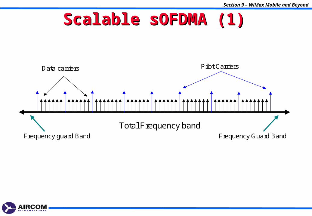
Scalable sOFDMA (1)Scalable sOFDMA (1)
Data carriers
Total Frequency band
Pilot Carriers
Frequency guard Band Frequency Guard Band
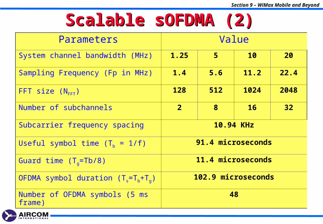
Scalable sOFDMA (2)Scalable sOFDMA (2)Section 9 – WiMax Mobile and Beyond
Parameters Value
System channel bandwidth (MHz) 1.25 5 10 20
Sampling Frequency (Fp in MHz) 1.4 5.6 11.2 22.4
FFT size (NFFT) 128 512 1024 2048
Number of subchannels 2 8 16 32
Subcarrier frequency spacing 10.94 KHz
Useful symbol time (Tb = 1/f) 91.4 microseconds
Guard time (Tg=Tb/8) 11.4 microseconds
OFDMA symbol duration (Ts=Tb+Tg) 102.9 microseconds
Number of OFDMA symbols (5 ms frame) 48
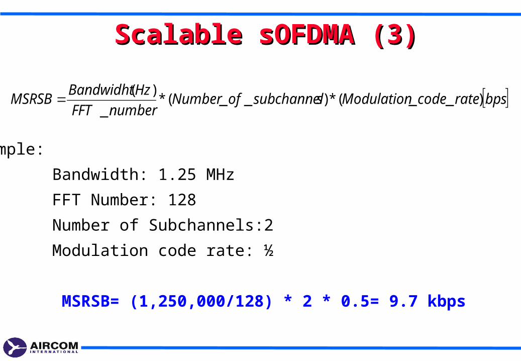
Scalable sOFDMA (3)Scalable sOFDMA (3)
bpsratecodeModulationssubchannelofNumbernumberFFT
HzBandwidhtMSRSB )__(*)__(*
_
)(
•Example:
Bandwidth: 1.25 MHz
FFT Number: 128
Number of Subchannels:2
Modulation code rate: ½
MSRSB= (1,250,000/128) * 2 * 0.5= 9.7 kbps
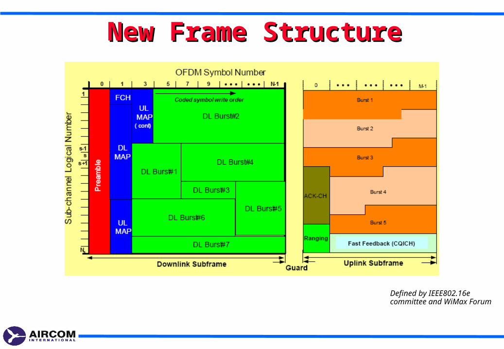
New Frame StructureNew Frame Structure
Defined by IEEE802.16e committee and WiMax Forum
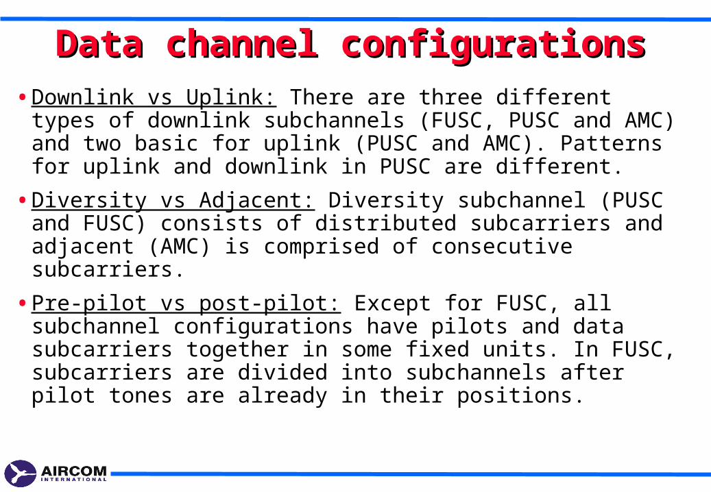
Data channel configurationsData channel configurations
• Downlink vs Uplink: There are three different types of downlink subchannels (FUSC, PUSC and AMC) and two basic for uplink (PUSC and AMC). Patterns for uplink and downlink in PUSC are different.
• Diversity vs Adjacent: Diversity subchannel (PUSC and FUSC) consists of distributed subcarriers and adjacent (AMC) is comprised of consecutive subcarriers.
• Pre-pilot vs post-pilot: Except for FUSC, all subchannel configurations have pilots and data subcarriers together in some fixed units. In FUSC, subcarriers are divided into subchannels after pilot tones are already in their positions.
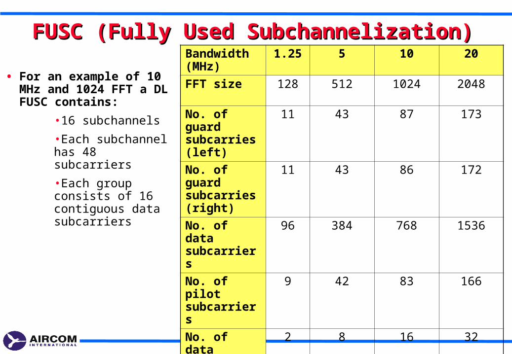
FUSC (Fully Used Subchannelization)FUSC (Fully Used Subchannelization)
• For an example of 10 MHz and 1024 FFT a DL FUSC contains:
•16 subchannels
•Each subchannel has 48 subcarriers
•Each group consists of 16 contiguous data subcarriers
Bandwidth (MHz)
1.25 5 10 20
FFT size 128 512 1024 2048
No. of guard subcarries (left)
11 43 87 173
No. of guard subcarries (right)
11 43 86 172
No. of data subcarriers
96 384 768 1536
No. of pilot subcarriers
9 42 83 166
No. of data subchannels
2 8 16 32
No. of subcarriers per subchannel
48 48 48 48
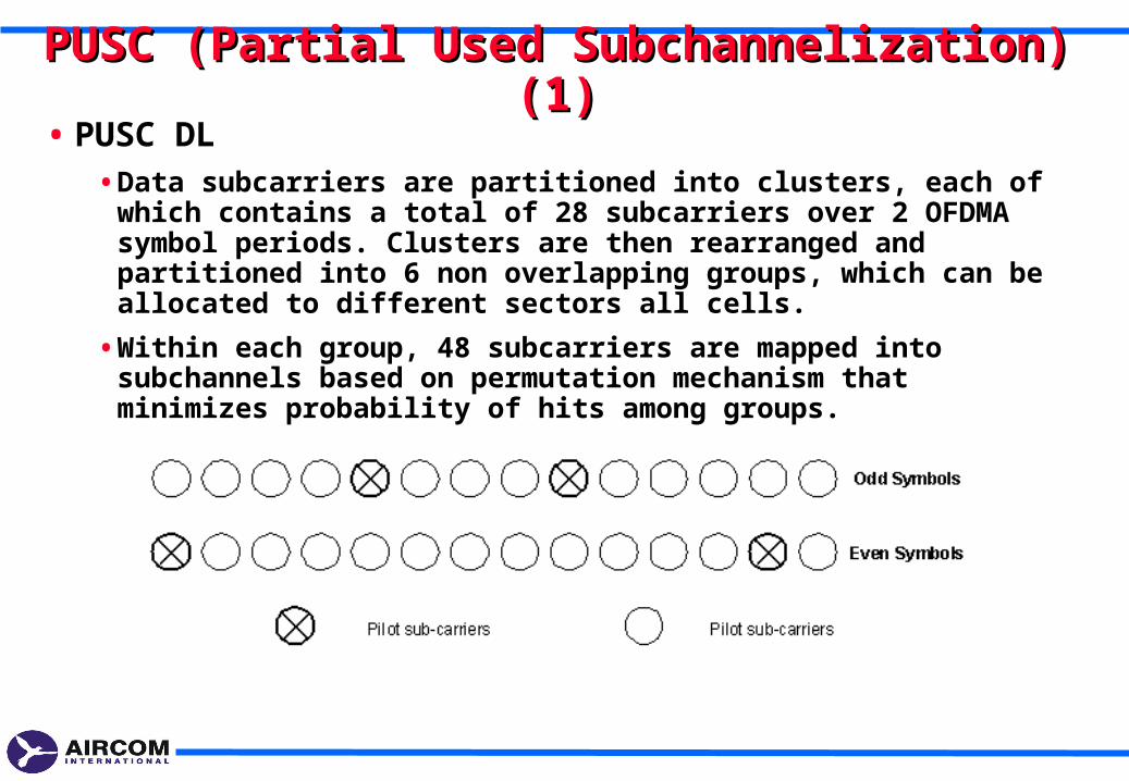
PUSC (Partial Used Subchannelization) (1)PUSC (Partial Used Subchannelization) (1)• PUSC DL
• Data subcarriers are partitioned into clusters, each of which contains a total of 28 subcarriers over 2 OFDMA symbol periods. Clusters are then rearranged and partitioned into 6 non overlapping groups, which can be allocated to different sectors all cells.
• Within each group, 48 subcarriers are mapped into subchannels based on permutation mechanism that minimizes probability of hits among groups.
PUSC (Partial Used Subchannelization) (2)PUSC (Partial Used Subchannelization) (2)
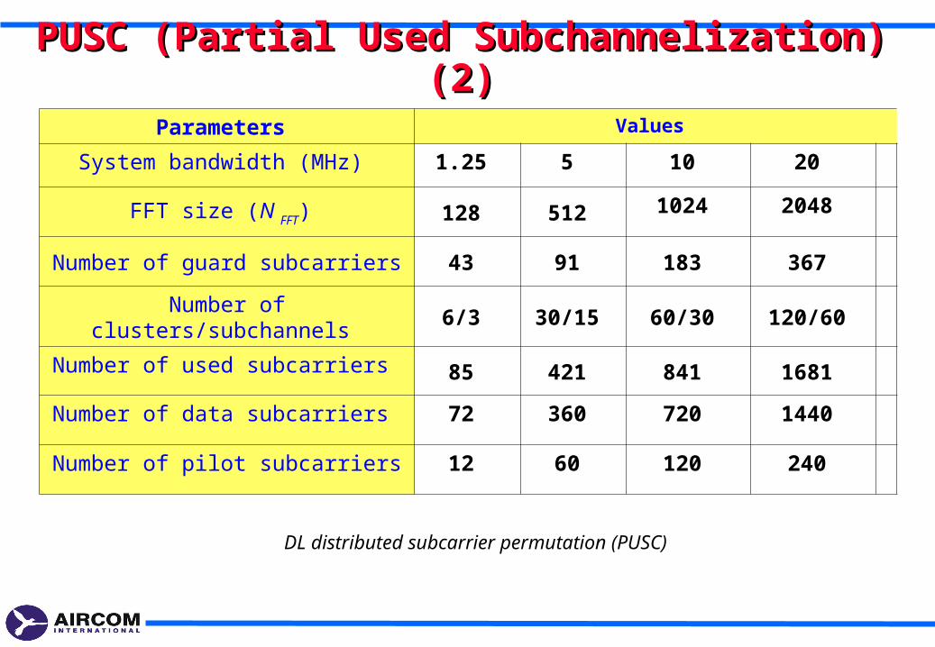
DL distributed subcarrier permutation (PUSC)
Parameters Values
System bandwidth (MHz) 1.25 5 10 20
FFT size (N FFT) 128 512 1024 2048
Number of guard subcarriers 43 91 183 367
Number of clusters/subchannels 6/3 30/15 60/30 120/60
Number of used subcarriers 85 421 841 1681
Number of data subcarriers 72 360 720 1440
Number of pilot subcarriers 12 60 120 240
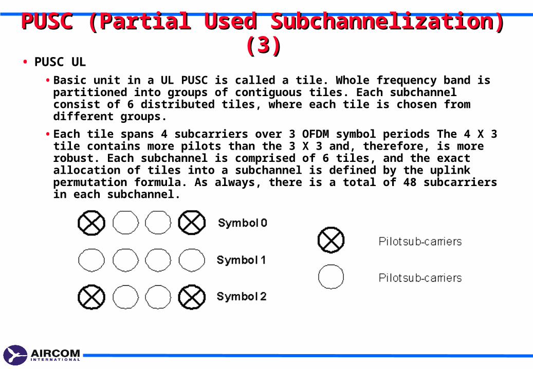
PUSC (Partial Used Subchannelization) (3)PUSC (Partial Used Subchannelization) (3)• PUSC UL
• Basic unit in a UL PUSC is called a tile. Whole frequency band is partitioned into groups of contiguous tiles. Each subchannel consist of 6 distributed tiles, where each tile is chosen from different groups.
• Each tile spans 4 subcarriers over 3 OFDM symbol periods The 4 X 3 tile contains more pilots than the 3 X 3 and, therefore, is more robust. Each subchannel is comprised of 6 tiles, and the exact allocation of tiles into a subchannel is defined by the uplink permutation formula. As always, there is a total of 48 subcarriers in each subchannel.
PUSC (Partial Used Subchannelization) (4)PUSC (Partial Used Subchannelization) (4)
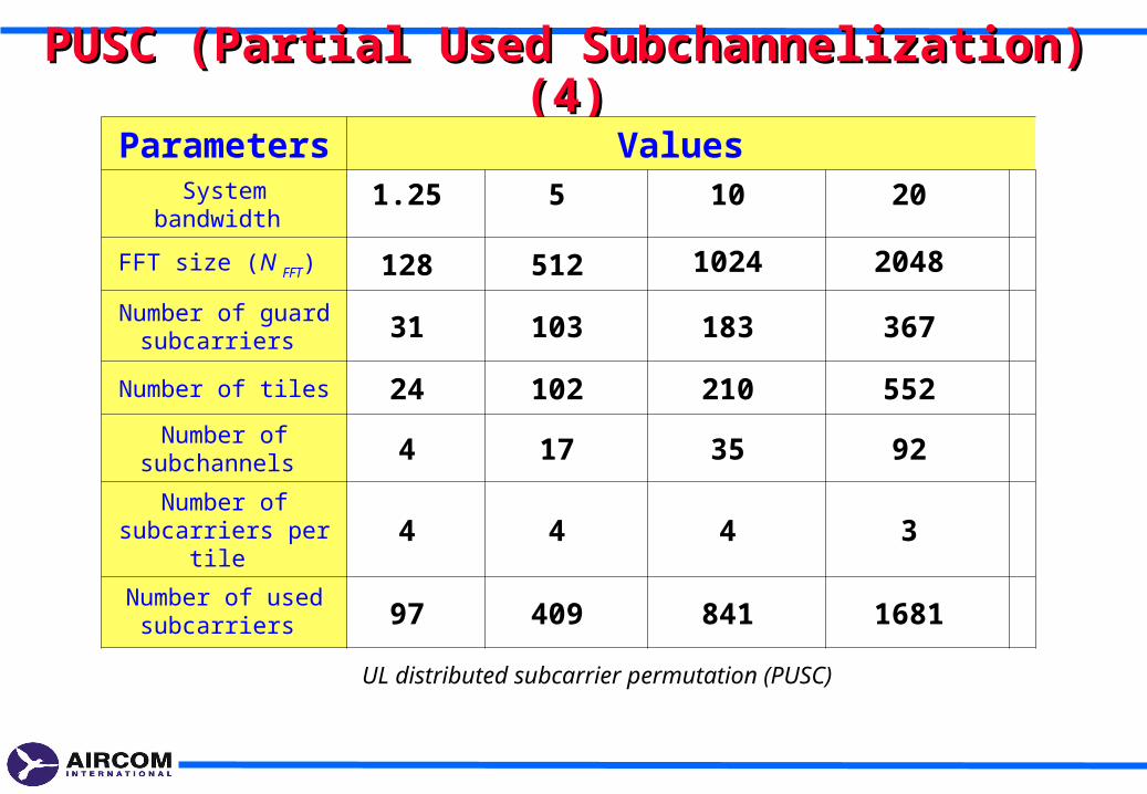
Parameters Values System bandwidth 1.25 5 10 20
FFT size (N FFT) 128 512 1024 2048
Number of guard subcarriers 31 103 183 367
Number of tiles 24 102 210 552
Number of subchannels 4 17 35 92
Number of subcarriers per tile 4 4 4 3
Number of used subcarriers 97 409 841 1681
UL distributed subcarrier permutation (PUSC)
AMC (Adaptive Modulation and Coding Scheme) AMC (Adaptive Modulation and Coding Scheme)
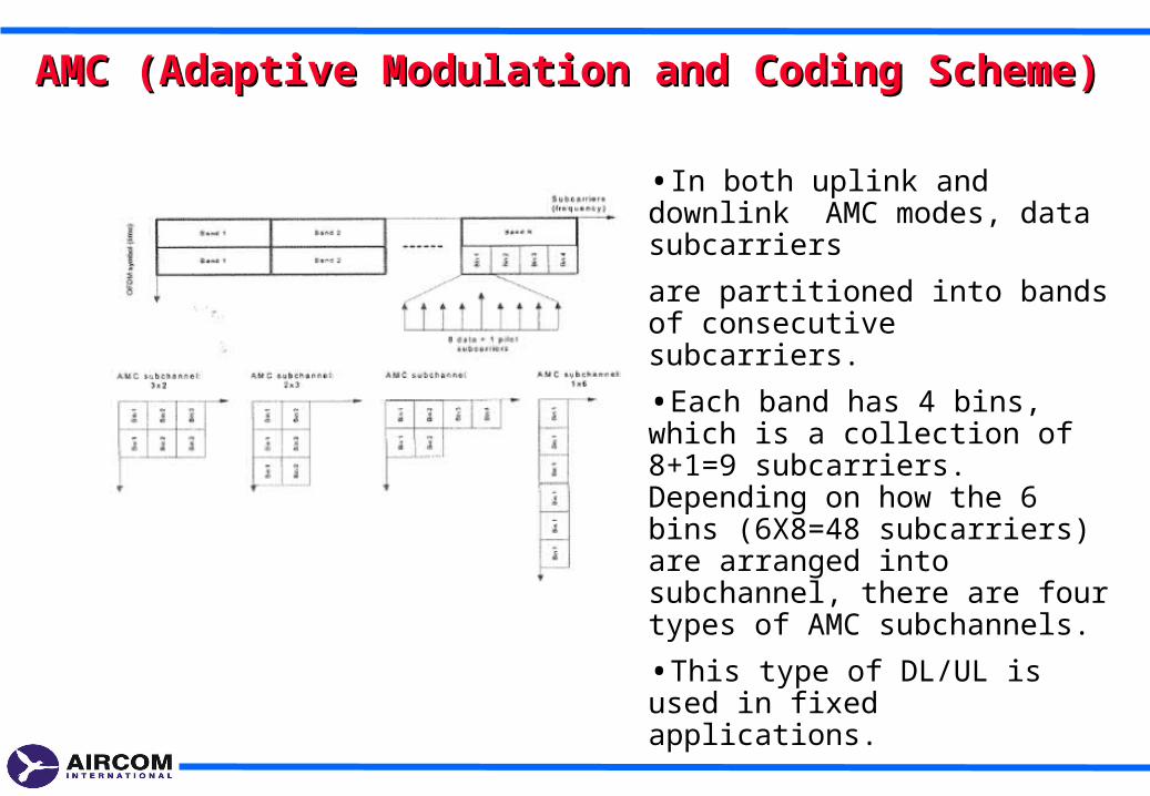
•In both uplink and downlink AMC modes, data subcarriers
are partitioned into bands of consecutive subcarriers.
•Each band has 4 bins, which is a collection of 8+1=9 subcarriers. Depending on how the 6 bins (6X8=48 subcarriers) are arranged into subchannel, there are four types of AMC subchannels.
•This type of DL/UL is used in fixed applications.
Modulation and channel codingModulation and channel coding
•BPSK, QPSK, 16QAM and 64QAM are supported for 802.16e, 64 QAM is optional for uplink.
•Channel coding options include:
•Repetition coding (2x, 4x and 6x) for control signals
•Convolutional coding (CC) with incremental redundancy
•Convolutional turbo coding (CTC) with incremental redundancy
•Block turbo coding (BTC)
•Low-density parity-check coding (LPDC)
Smart antennas technologies (1)Smart antennas technologies (1)
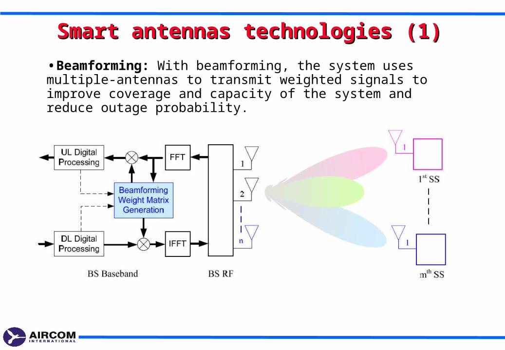
•Beamforming: With beamforming, the system uses multiple-antennas to transmit weighted signals to improve coverage and capacity of the system and reduce outage probability.
Smart antennas technologies (2)Smart antennas technologies (2)
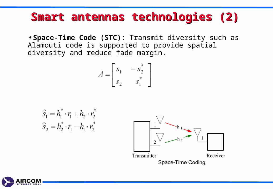
•Space-Time Code (STC): Transmit diversity such as Alamouti code is supported to provide spatial diversity and reduce fade margin.
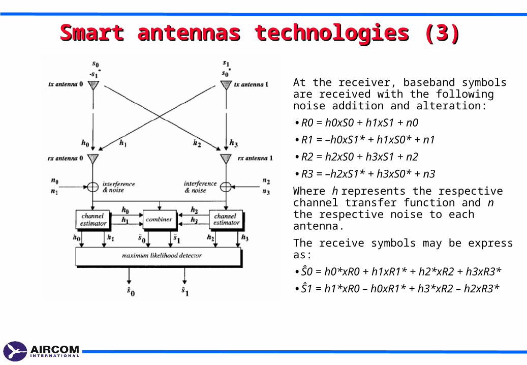
Smart antennas technologies (3)Smart antennas technologies (3)
At the receiver, baseband symbols are received with the following noise addition and alteration:
•R0 = h0xS0 + h1xS1 + n0
•R1 = –h0xS1* + h1xS0* + n1
•R2 = h2xS0 + h3xS1 + n2
•R3 = –h2xS1* + h3xS0* + n3
Where h represents the respective channel transfer function and n the respective noise to each antenna.
The receive symbols may be express as:
•Ŝ0 = h0*xR0 + h1xR1* + h2*xR2 + h3xR3*
•Ŝ1 = h1*xR0 – h0xR1* + h3*xR2 – h2xR3*
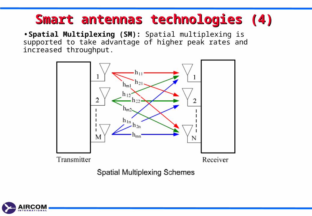
•Spatial Multiplexing (SM): Spatial multiplexing is supported to take advantage of higher peak rates and increased throughput.
Smart antennas technologies (4)Smart antennas technologies (4)
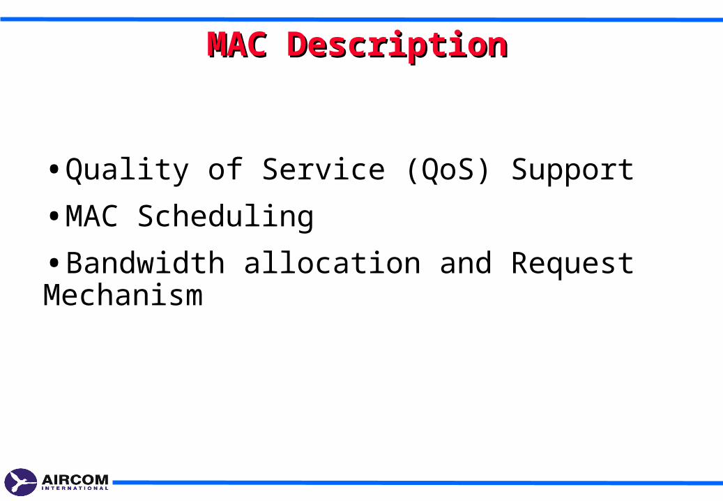
•Quality of Service (QoS) Support
•MAC Scheduling
•Bandwidth allocation and Request Mechanism
MAC DescriptionMAC Description
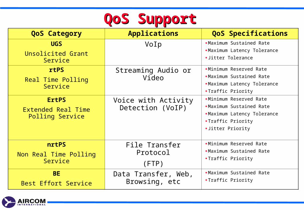
QoS SupportQoS SupportQoS Category Applications QoS Specifications
UGS
Unsolicited Grant Service
VoIp •Maximum Sustained Rate
•Maximum Latency Tolerance
•Jitter Tolerance
rtPS
Real Time Polling Service
Streaming Audio or Video •Minimum Reserved Rate
•Maximum Sustained Rate
•Maximum Latency Tolerance
•Traffic Priority
ErtPS
Extended Real Time Polling Service
Voice with Activity Detection (VoIP)
•Minimum Reserved Rate
•Maximum Sustained Rate
•Maximum Latency Tolerance
•Traffic Priority
•Jitter Priority
nrtPS
Non Real Time Polling Service
File Transfer Protocol
(FTP)
•Minimum Reserved Rate
•Maximum Sustained Rate
•Traffic Priority
BE
Best Effort Service
Data Transfer, Web, Browsing, etc
•Maximum Sustained Rate
•Traffic Priority
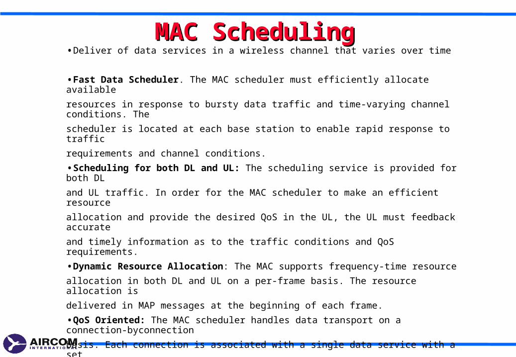
MAC SchedulingMAC Scheduling•Deliver of data services in a wireless channel that varies over time
•Fast Data Scheduler. The MAC scheduler must efficiently allocate available
resources in response to bursty data traffic and time-varying channel conditions. The
scheduler is located at each base station to enable rapid response to traffic
requirements and channel conditions.
•Scheduling for both DL and UL: The scheduling service is provided for both DL
and UL traffic. In order for the MAC scheduler to make an efficient resource
allocation and provide the desired QoS in the UL, the UL must feedback accurate
and timely information as to the traffic conditions and QoS requirements.
•Dynamic Resource Allocation: The MAC supports frequency-time resource
allocation in both DL and UL on a per-frame basis. The resource allocation is
delivered in MAP messages at the beginning of each frame.
•QoS Oriented: The MAC scheduler handles data transport on a connection-byconnection
basis. Each connection is associated with a single data service with a set
of QoS parameters that quantify the aspects of its behavior.
•Frequency Selective Scheduling: The scheduler can operate on different types of
sub-channels. For frequency-diverse sub-channels such as PUSC permutation, where
sub-carriers in the sub-channels are pseudo-randomly distributed across the
bandwidth, sub-channels are of similar quality.
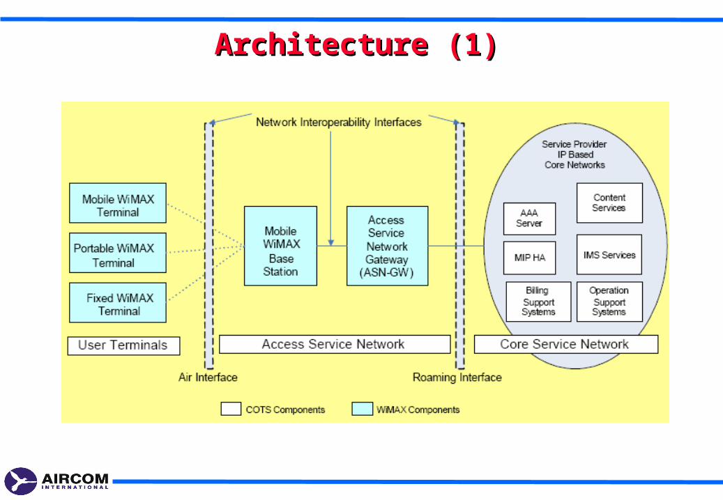
Architecture (1)Architecture (1)
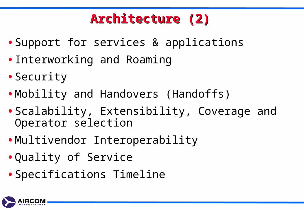
• Support for services & applications
• Interworking and Roaming
• Security
• Mobility and Handovers (Handoffs)
• Scalability, Extensibility, Coverage and Operator selection
• Multivendor Interoperability
• Quality of Service
• Specifications Timeline
Architecture (2)Architecture (2)
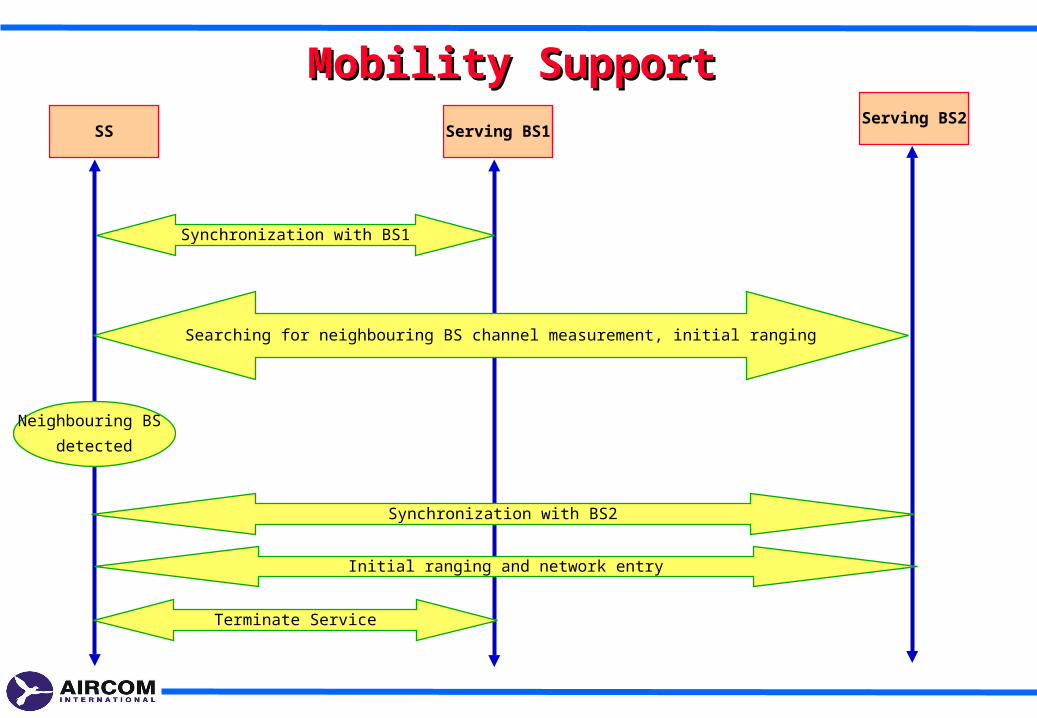
Mobility SupportMobility SupportSS Serving BS1
Serving BS2
Synchronization with BS1
Searching for neighbouring BS channel measurement, initial ranging
Synchronization with BS2
Initial ranging and network entry
Terminate Service
Neighbouring BS
detected
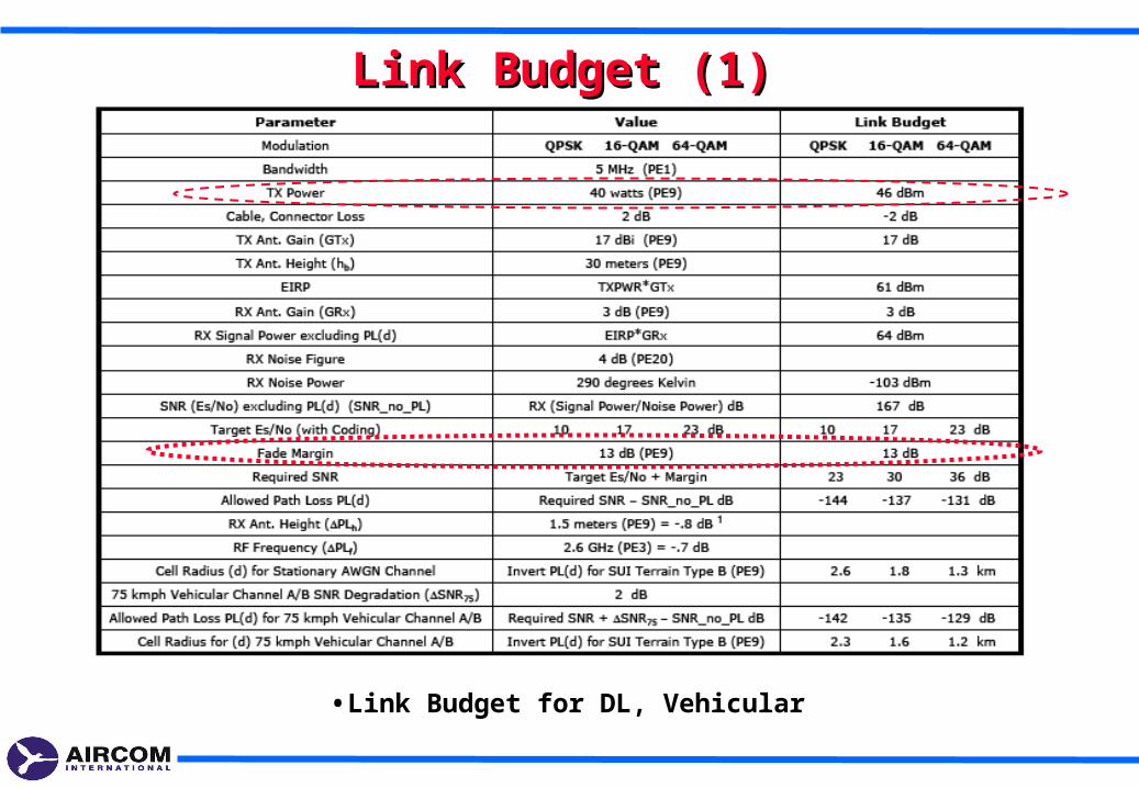
Link Budget (1)Link Budget (1)
•Link Budget for DL, Vehicular
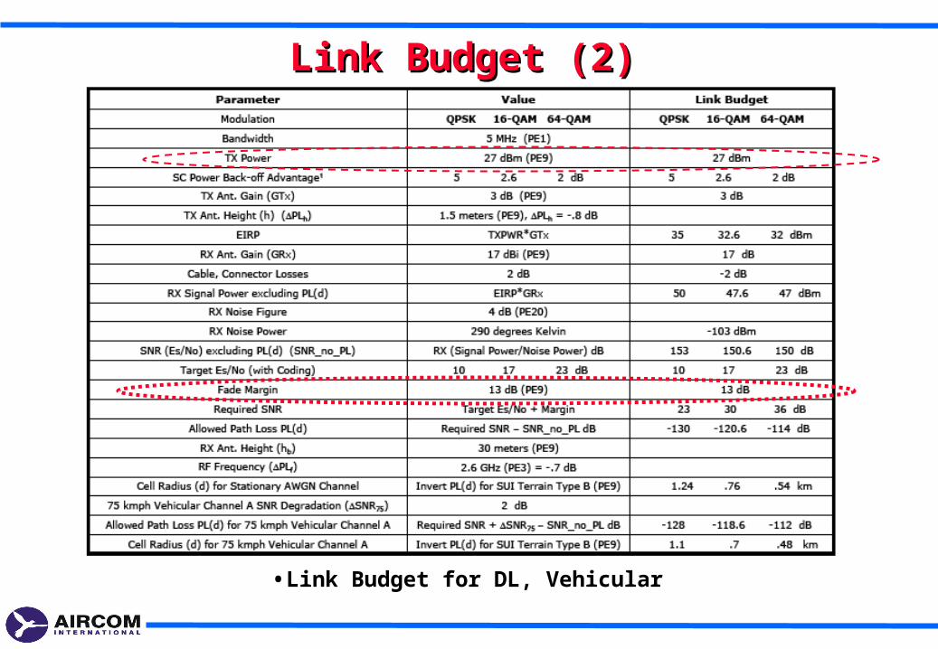
Link Budget (2)Link Budget (2)
•Link Budget for DL, Vehicular

End of CourseEnd of Course