Embed Size (px)
Citation preview
0
A Cross-Layer Radio Resource Management inWiMAX Systems
Sondes Khemiri Guy Pujolle1 and Khaled Boussetta Nadjib Achir2
1LIP6, University Paris 6, Paris2L2TI, University Paris 13, Villetaneuse
1France
1. Introduction
This chapter addresses the issue of a cross layer radio resource management in IEEE 802.16metropolitan network and focuses specially on IEEE 802.16e-2005 WiMAX network withWireless MAN OFDMA physical layer. A wireless bandwidth allocation strategy for a mobileWiMAX network is very important since it determines the maximum average number of usersaccepted in the network and consequently the provider gain.
The purpose of the chapter is to give an overview of a cross-layer resource allocationmechanisms and describes optimization problems with an aim to fulfill three objectives: (i)to maximize the utilisation ratio of the wireless link, (ii) to guarantee that the system satisfiesthe QoS constraints of application carried by subscribers and (iii) to take into account the radiochannel environment and the system specifications.
The chapter is organized as follows: Section 1 and 2 describe the most important conceptsdefined by IEEE 802.16e-2005 standard in physical and MAC layer, Section 3 presents anoverview of QoS mechanisms described in the literature, Section 4 gives a guideline tocompute a physical slot capacity needed in resource allocation problems, the cross-layerresource management problem formalization is detailed in section 5. Solutions are presentedin section 6. Finally, section 7 summarizes the chapter.
2. Mobile WiMAX overview
This section presents an overview of the most important concepts defined by IEEE802.16e-2005 standard in physical and MAC layer, that are needed in order to define a systemcapacity.
2.1 WiMAX PHY layer
We will give in this section details about PHY layer and we will focus specially on specifiedconcepts that must be taken into account in allocation bandwidth problem namely, thespecification of the PHY layer, the OFDMA multiplexing scheme and the permutation schemefor sub-channelization from which we deduce the bandwidth unit allocated to accepted callsin the system and the Adaptive Modulation and Coding scheme (AMC).
7
www.intechopen.com
2 Will-be-set-by-IN-TECH
2.1.1 Generality
The IEEE 802.16 defines five PHY layers which can be used with a MAC layer to form abroadband wireless system.
These PHY layers provide a large flexibility in terms of bandwidth channel, duplexing schemeand channel condition. These layers are described as follows:
1. WirelessMAN SC: In this PHY layer single carriers are used to transmit information forfrequencies beyond 11GHz in a Line of sight (LOS) condition.
2. WirelessMAN SCa: it also relies on a single carrier transmission scheme, but forfrequencies between 2 GHz and 11GHz.
3. WirelessMAN OFDM (Orthogonal Frequency Division Multiplexing): it is based on a FastFourier Transform (FFT) with a size of 256 points. It is used for point multipoint link in anon-LOS condition for frequencies between 2 GHz and 11GHz.
4. WirelessMAN OFDMA (OFDM Access): Also referred as mobile WiMAX , it is also basedon a FFT with a size of 2048 points. It is used in a non LOS condition for frequenciesbetween 2 GHz and 11GHz.
5. Finally a WirelessMAN SOFDMA (SOFDM Access): OFDMA PHY layer has beenextended in IEEE 802.16e to SOFDMA (scalable OFDMA) where the size is variable andcan take different values: 128, 512, 1024, and 2048.
In this chapter we will focus only on the WirelessMAN OFDMA PHY layer. As we saw inprevious paragraph many combination of configuration parameters like band frequencies,channel bandwidth and duplexing techniques are possible. To insure interoperability betweenterminals and base stations the WiMAX Forum has defined a set of WiMAX system profiles.The latter are basically a set of fixed configuration parameters.
2.1.2 OFDM, OFDMA and subchannelization
The WiMAX PHY layer has also the responsibility of resource allocation and framing overthe radio channel. In follows, we will define this physical resource. In fact, the mobileWiMAX physical layer is based on Orthogonal Frequency Multiple Access (OFDMA), which isa multi-users extension of Orthogonal Frequency-Division Multiplexing (OFDM) technique.The latter principles consist of a simultaneous transmission of a bit stream over orthogonalfrequencies, also called OFDM sub-carriers. Precisely, the total bandwidth is divided into anumber of orthogonal sub-carriers. As described in mobile WiMAX (Jeffrey G. et al., 2007),the OFDMA sharing capabilities are augmented in multi-users context thanks to the flexibleability of the standard to divide the frequency/time resources between users. The minimumtime-frequency resource that can be allocated by a WiMAX system to a given link is called aslot. Precisely, the basic unit of allocation in the time-frequency grid is named a slot. Broadlyspeaking, a slot is an n x m rectangle, where n is a number of sub-carriers called sub-channelin the frequency domain and m is a number of contiguous symbols in the time domain.
WiMAX defines several sub-channelization schemes. The sub-channelization could beadjacent i.e. sub-carriers are grouped in the same frequency range in each sub-channel ordistributed i.e. sub-carriers are pseudo-randomly distributed across the frequency spectrum.So we can find:
• Full usage sub-carriers (FUSC): Each slot is 48 sub-carriers by one OFDM symbol.
148 Quality of Service and Resource Allocation in WiMAX
www.intechopen.com
A Cross-Layer Radio Resource Management in WiMAX Systems 3
• Down-link Partial Usage of Sub-Carrier (PUSC): Each slot is 24 sub-carriers by two OFDMsymbols.
• Up-link PUSC and TUSC Tile Usage of Sub-Carrier: Each slot is 16 sub-carriers by threeOFDM symbols.
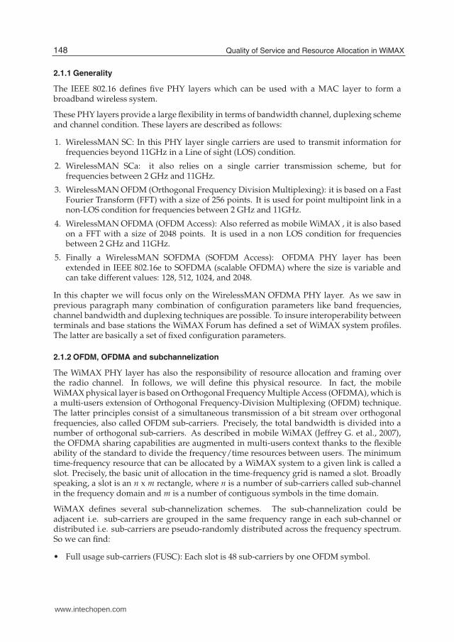
• Band Adaptive Modulation and Coding (BAMC) : As we see in figure 1 each slot is 8, 16,or 24 sub-carriers by 6, 3, or 2 OFDM symbols.
Fig. 1. BAMC slot format
In this chapter we will focus on the last permutation scheme i.e BAMC and we will explainhow to compute the slot capacity.
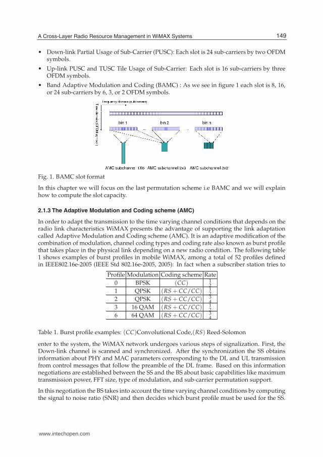
2.1.3 The Adaptive Modulation and Coding scheme (AMC)
In order to adapt the transmission to the time varying channel conditions that depends on theradio link characteristics WiMAX presents the advantage of supporting the link adaptationcalled Adaptive Modulation and Coding scheme (AMC). It is an adaptive modification of thecombination of modulation, channel coding types and coding rate also known as burst profilethat takes place in the physical link depending on a new radio condition. The following table1 shows examples of burst profiles in mobile WiMAX, among a total of 52 profiles definedin IEEE802.16e-2005 (IEEE Std 802.16e-2005, 2005): In fact when a subscriber station tries to
Profile Modulation Coding scheme Rate
0 BPSK (CC) 12
1 QPSK (RS + CC/CC) 12
2 QPSK (RS + CC/CC) 34
3 16 QAM (RS + CC/CC) 12
6 64 QAM (RS + CC/CC) 34
Table 1. Burst profile examples: (CC)Convolutional Code,(RS) Reed-Solomon
enter to the system, the WiMAX network undergoes various steps of signalization. First, theDown-link channel is scanned and synchronized. After the synchronization the SS obtainsinformation about PHY and MAC parameters corresponding to the DL and UL transmissionfrom control messages that follow the preamble of the DL frame. Based on this informationnegotiations are established between the SS and the BS about basic capabilities like maximumtransmission power, FFT size, type of modulation, and sub-carrier permutation support.
In this negotiation the BS takes into account the time varying channel conditions by computingthe signal to noise ratio (SNR) and then decides which burst profile must be used for the SS.
149A Cross-Layer Radio Resource Management in WiMAX Systems
www.intechopen.com
4 Will-be-set-by-IN-TECH
In fact, using the channel quality feedback indicator, the downlink SNR is provided by themobile to the base station. For the uplink, the base station can estimate the channel quality,based on the received signal quality.
Based on these informations on signal quality, different modulation schemes will be employedin the same network in order to maximize throughput in a time-varying channel. Indeed,whenthe distance between the base station and the subscriber station increases the signal tothe noise ratio decreases due to the path loss. Consequantely, modulation must be useddepending on the station position starting from the lower efficiency modulation (for terminalsnear the BS) to the higher efficiency modulation (for terminals far away from the BS).
2.2 WiMAX MAC layer and QoS overview
The primary task of the WiMAX MAC layer is to provide an interface between the highertransport layers and the physical layer. The IEEE 802.16-2004 and IEEE 802.16e-2005 MACdesign includes a convergence sublayer that can interface with a variety of higher-layerprotocols, such as ATM,TDM Voice, Ethernet, IP, and any unknown future protocol.
Support for QoS is a fundamental part of the WiMAX MAC-layer design. QoS control isachieved by using a connection-oriented MAC architecture, where all downlink and uplinkconnections are controlled by the serving BS. Before any data transmission happens, theBS and the MS establish a unidirectional logical link, called a connection, between the twoMAC-layer peers. Each connection is identified by a connection identifier (CID), which servesas a temporary address for data transmissions over the particular link. WiMAX also defines aconcept of a service flow. A service flow is a unidirectional flow of packets with a particularset of QoS parameters and is identified by a service flow identifier (SFID). The QoS parameterscould include traffic priority, maximum sustained traffic rate, maximum burst rate, minimumtolerable rate, scheduling type, ARQ type, maximum delay, tolerated jitter, service data unittype and size, bandwidth request mechanism to be used, transmission PDU formation rules,and so on. Service flows may be provisioned through a network management system orcreated dynamically through defined signaling mechanisms in the standard. The base stationis responsible for issuing the SFID and mapping it to unique CIDs. In the following, we willpresent the service classes of mobile WiMAX characterized by these SFIDs.
2.2.1 WiMAX service classes
Mobile WiMAX is emerging as one of the most promising 4G technology. It has beendeveloped keeping in view the stringent QoS requirements of multimedia applications.Indeed, the IEEE 802.16e 2005 standard defines five QoS scheduling services that should betreated appropriately by the base station MAC scheduler for data transport over a connection:
1. Unsolicited Grant Service (UGS) is dedicated to real-time services that generate CBR orCBR-like flows. A typical application would be Voice over IP, without silence suppression.
2. Real-Time Polling Service (rtPS) is designed to support real-time services that generatedelay sensitive VBR flows, such as MPEG video or VoIP (with silence suppression).
3. Non-Real-Time Polling Service (nrtPS) is designed to support delay-tolerant data deliverywith variable size packets, such as high bandwidth FTP.
4. Best Effort (BE) service is proposed to be used for all applications that do not require anyQoS guarantees.
150 Quality of Service and Resource Allocation in WiMAX
www.intechopen.com
A Cross-Layer Radio Resource Management in WiMAX Systems 5
5. Extended Real-Time Polling Service (ErtPS) is expected to provide VoIP services with VoiceActivation Detection (VAD).
Note that the standard defines 4 service classes for Fixed WiMAX: UGS, rtPS, nrtPS and BE.
In order to guarantee the QoS for these different service classes Call Admission Control (CAC)and resource reservation strategies are needed by the IEE 802.16e system.
2.2.2 QoS mechanisms in WiMAX
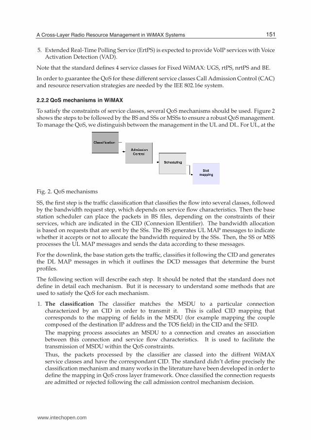
To satisfy the constraints of service classes, several QoS mechanisms should be used. Figure 2shows the steps to be followed by the BS and SSs or MSSs to ensure a robust QoS management.To manage the QoS, we distinguish between the management in the UL and DL. For UL, at the
Fig. 2. QoS mechanisms
SS, the first step is the traffic classification that classifies the flow into several classes, followedby the bandwidth request step, which depends on service flow characteristics. Then the basestation scheduler can place the packets in BS files, depending on the constraints of theirservices, which are indicated in the CID (Connexion IDentifier). The bandwidth allocationis based on requests that are sent by the SSs. The BS generates UL MAP messages to indicatewhether it accepts or not to allocate the bandwidth required by the SSs. Then, the SS or MSSprocesses the UL MAP messages and sends the data according to these messages.
For the downlink, the base station gets the traffic, classifies it following the CID and generatesthe DL MAP messages in which it outlines the DCD messages that determine the burstprofiles.
The following section will describe each step. It should be noted that the standard does notdefine in detail each mechanism. But it is necessary to understand some methods that areused to satisfy the QoS for each mechanism.
1. The classification The classifier matches the MSDU to a particular connectioncharacterized by an CID in order to transmit it. This is called CID mapping thatcorresponds to the mapping of fields in the MSDU (for example mapping the couplecomposed of the destination IP address and the TOS field) in the CID and the SFID.
The mapping process associates an MSDU to a connection and creates an associationbetween this connection and service flow characteristics. It is used to facilitate thetransmission of MSDU within the QoS constraints.
Thus, the packets processed by the classifier are classed into the diffrent WiMAXservice classes and have the correspondant CID. The standard didn’t define precisely theclassification mechanism and many works in the literature have been developed in order todefine the mapping in QoS cross layer framework. Once classified the connection requestsare admitted or rejected following the call admission control mechanism decision.
151A Cross-Layer Radio Resource Management in WiMAX Systems
www.intechopen.com
6 Will-be-set-by-IN-TECH
2. Call admission control (CAC) and Bandwidth Allocation As in cellular networks, theIEEE 802.16 Base Station MAC layer is in charge to regulate and control bandwidthallocation. Therefore, incorporating a Call Admission Control (CAC) agent becomes theprimary method to allocate network resources in such a way that the QoS user constraintscould be satisfied. Before any connection establishment, each SS informs the BS about itsQoS requirements. And the BS CAC agent have the responsability to determine whethera connection request can be accepted or should be rejected. The rejection of requesthappens if its QoS requirements cannot be satisfied or if its acceptance may violate theQoS guarantee of ongoing calls.
To well manage the operation of this step, the WiMAX standard provides tools andmechanisms for bandwidth allocation and request that is described briefly as follows:
(a) Bandwidth request At the entrance to the network, each SS or MSS is allocated up to3 dedicated CID identifiers. These CIDs are used to send and receive control messages.Among these messages one can distinguish Up-link Channel Descriptor, DownlinkChannel Descriptor, UL-MAP and DL-MAP messages, plus messages concerning thebandwidth request. The latter can be sent by the SS following one of these modes:
• Implicit Requests: This mode corresponds to UGS traffic which requires a fixed bitrate and does not require any negotiation.
• Bandwidth request message: This message type uses headers named BW request. Itreaches a length of 32 KB per request by CID.
• Piggybacked request: is integrated into useful messages and is used for all serviceclasses, except for UGS.
• Request by the bit Poll-Me: is used by the SS to request bandwidth for non-UGSservices.
(b) Bandwidth Allocation modes
There are two modes of bandwidth allocation:
• The Grant Per Subscriber Station (GPSS): In this mode, the BS guarantes theaggregated bandwidth per SS. Then the SS allocates the required bandwidth foreach connection that it carries. This allocation must be performed by a schedulingalgorithm. This method has the advantage of having multiple users by SS andtherefore requires less overhead. However, it is more complex to implement becauseit requires sophisticated SSs that support a hierarchical distributed scheduler.
• The Grant Per Connection (GPC): In this type of allocation the BS guarantesthe bandwidth per connection, which is identified thanks to the individual CID(Connection IDentifier). This method has the advantage of being simpler to designthan the GPSS mode but is adapted for a small number of users per SS and providesmore overhead than the first mode.
Thus, based on SS and MSS requests the base station can satisfy the other QoSapplication constraints by employing different allocation bandwidth strategies and calladmission control policies. Recall that the latters have not been defined in the standard.
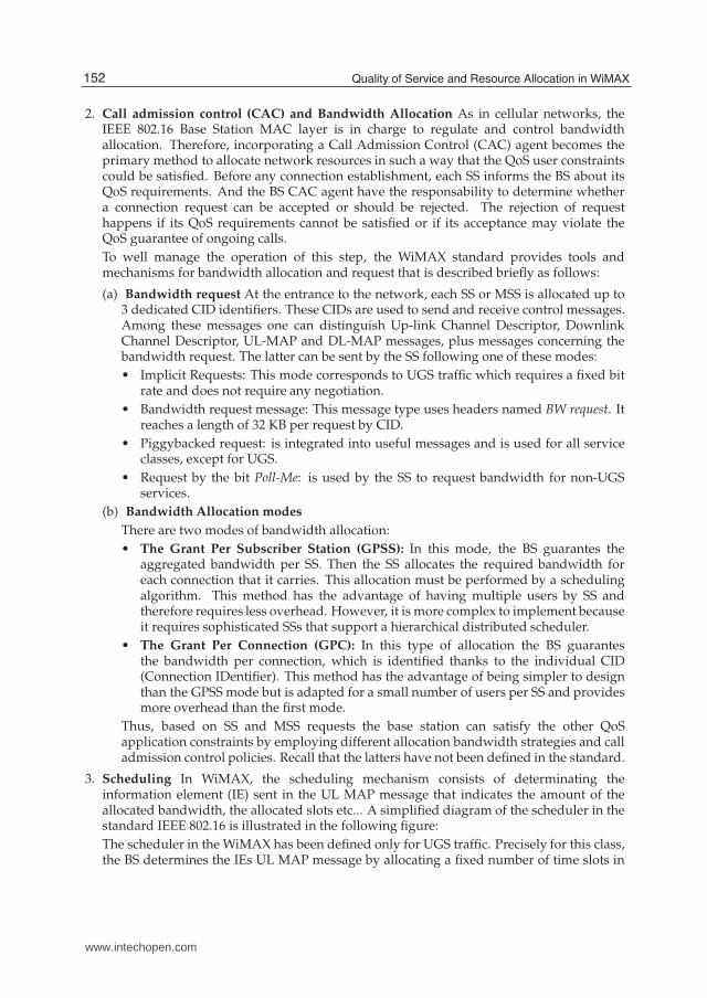
3. Scheduling In WiMAX, the scheduling mechanism consists of determinating theinformation element (IE) sent in the UL MAP message that indicates the amount of theallocated bandwidth, the allocated slots etc... A simplified diagram of the scheduler in thestandard IEEE 802.16 is illustrated in the following figure:
The scheduler in the WiMAX has been defined only for UGS traffic. Precisely for this class,the BS determines the IEs UL MAP message by allocating a fixed number of time slots in
152 Quality of Service and Resource Allocation in WiMAX
www.intechopen.com
A Cross-Layer Radio Resource Management in WiMAX Systems 7
Fig. 3. Scheduler in IEEE 802.16 standard
each frame interval. The BS must take into account the state of queues associated to trafficand all queues among the SS, corresponding to UL traffic. For the remaining traffic classesthe standard does not specify a particular scheduling algorithm, and left the choice to theoperator to implement one of the algorithm that was described in the literature (JianfengC. et al., 2005) (Wongthavarawat K. et al, 2003).
4. The mapping
This is the final step before sending user data in the radio channel. The idea is to assignsub-carriers in the most efficient possible way to scheduled MPDUs in order to satisfyQoS constraints of each connection. The mapping mechanism is left to the choice of theprovider.
3. State of the art
3.1 Bandwidth sharing strategies: background
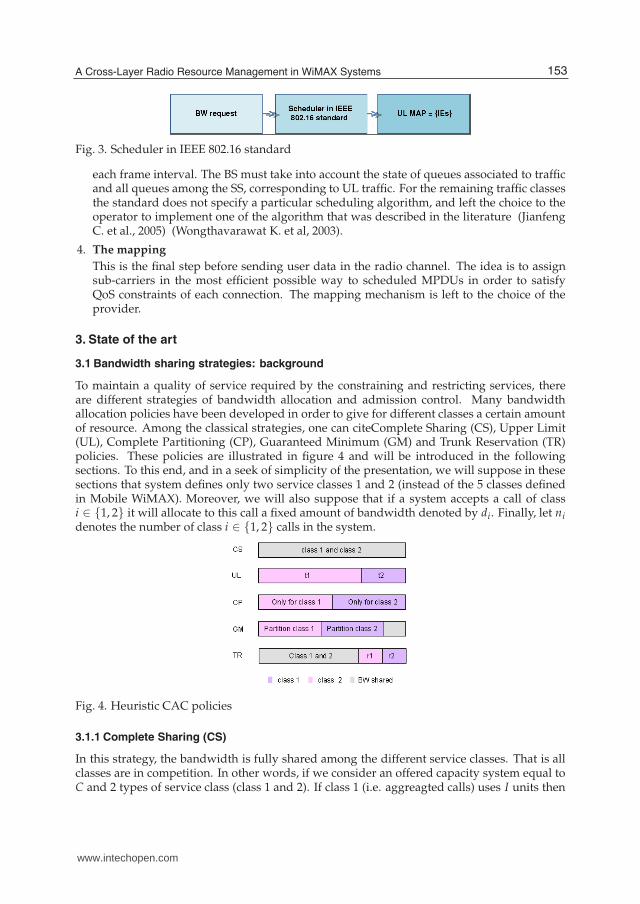
To maintain a quality of service required by the constraining and restricting services, thereare different strategies of bandwidth allocation and admission control. Many bandwidthallocation policies have been developed in order to give for different classes a certain amountof resource. Among the classical strategies, one can citeComplete Sharing (CS), Upper Limit(UL), Complete Partitioning (CP), Guaranteed Minimum (GM) and Trunk Reservation (TR)policies. These policies are illustrated in figure 4 and will be introduced in the followingsections. To this end, and in a seek of simplicity of the presentation, we will suppose in thesesections that system defines only two service classes 1 and 2 (instead of the 5 classes definedin Mobile WiMAX). Moreover, we will also suppose that if a system accepts a call of classi ∈ {1, 2} it will allocate to this call a fixed amount of bandwidth denoted by di. Finally, let nidenotes the number of class i ∈ {1, 2} calls in the system.
Fig. 4. Heuristic CAC policies
3.1.1 Complete Sharing (CS)
In this strategy, the bandwidth is fully shared among the different service classes. That is allclasses are in competition. In other words, if we consider an offered capacity system equal toC and 2 types of service class (class 1 and 2). If class 1 (i.e. aggreagted calls) uses I units then
153A Cross-Layer Radio Resource Management in WiMAX Systems
www.intechopen.com
8 Will-be-set-by-IN-TECH
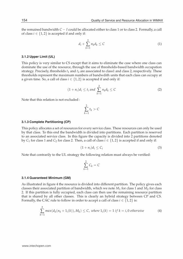
the remained bandwidth C − I could be allocated either to class 1 or to class 2. Formally, a callof class i ∈ {1, 2} is accepted if and only if:
di +2
∑k=1
nkdk ≤ C (1)
3.1.2 Upper Limit (UL)
This policy is very similar to CS except that it aims to eliminate the case where one class candominate the use of the resource, through the use of thresholds-based bandwidth occupationstrategy. Precisely, thresholds t1 and t2 are associated to class1 and class 2, respectively. Thesethresholds represent the maximum numbers of bandwdith units that each class can occupy ata given time. So, a call of class i ∈ {1, 2} is accepted if and only if:
(1 + ni)di ≤ ti and2
∑k=1
nkdk ≤ C (2)
Note that this relation is not excluded :
2
∑k=1
tk > C
3.1.3 Complete Partitioning (CP)
This policy allocates a set of resources for every service class. These resources can only be usedby that class. To this end the bandwidth is divided into partitions. Each partition is reservedto an associated service class. In this figure the capacity is divided into 2 partitions denotedby C1 for class 1 and C2 for class 2. Then, a call of class i ∈ {1, 2} is accepted if and only if:
(1 + ni)di ≤ Ci (3)
Note that contrarily to the UL strategy the following relation must always be verified:
2
∑k=1
Ck = C
3.1.4 Guaranteed Minimum (GM)
As illustrated in figure 4 the resource is divided into different partition. The policy gives eachclasses their associated partition of bandwidth, which we note M1 for class 1 and M2 for class2. If this partition is fully occupied, each class can then use the remaining resource partitionthat is shared by all other classes. This is clearly an hybrid strategy between CP and CS.Formally, the CAC rule to follow in order to accept a call of class i ∈ {1, 2} is:
2
∑k=1
max(dk(nk + 1i(k)), Mk) ≤ C, where 1i(k) = 1 i f k = i, 0 otherwise (4)
154 Quality of Service and Resource Allocation in WiMAX
www.intechopen.com
A Cross-Layer Radio Resource Management in WiMAX Systems 9
Note that the following relation must always be verified:
2
∑k=1
Mk ≤ C.
3.1.5 Trunk Reservation (TR)
As illustrated in figure 4, there are not dedicated partitions per classes in this policy. In fact,class i ∈ {1, 2} may use resources in a system as long as the amount of remaining resources isequal to a certain threshold ri ∈ {1, 2} bandwidth units. Thus each service class will protectedthank to thresholds, which will avoid that any class occupies the totality of resource units. Soa call of class i ∈ {1, 2} is accepted if and only if:
di +2
∑k=1
nkdk ≤ C − ri (5)
This rule guarantees that after applying this CAC policy and accepting the class i theremaining bandwidth is equal to ri. Several comparison have been made between thesepolicies and with optimal solution. One important challenge is to explain the method thatthresholds imposed by GM, UL and CP strategies are computed or determined which isexplained in (Khemiri S. et al., 2007).
So the main challenge is to setup these policy in an optimized way. This is could be doneby choosing the optimal partition sizes or reservation thresholds in order to 1) guarantee theQoS constraints of the application provided by the system and in the other words to satisfysubscribers and 2) to provide a good system performance which satisfies the provider.
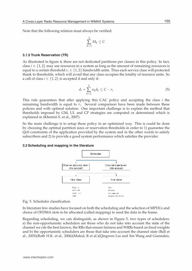
3.2 Scheduling and mapping in the literature
Fig. 5. Scheduler classification
In literature few studies have focused on both the scheduling and the selection of MPDUs andchoice of OFDMA slots to be allocated (called mapping) to send the data in the frame.
Regarding scheduling, we can distinguish, as shown in Figure 5, two types of schedulers:a) the non-opportunistic schedulers are those who do not take into account the state of thechannel we cite the best known, the RRs that ensure fairness and WRRs based on fixed weightsand b) the opportunistic schedulers are those that take into account the channel state (Ball etal., 2005)(Rath H.K. et al., 2006)(Mukul, R et al.)(Qingwen Liu and Xin Wang and Giannakis,
155A Cross-Layer Radio Resource Management in WiMAX Systems
www.intechopen.com
10 Will-be-set-by-IN-TECH
G.B. et al.)(Mohammud Z. et al., 2010) an example is the MAXSNR which first selects the MSSsthat have the maximum SIR. In (Ball et al., 2005), the authors present an algorithm called TRSthat removes from queues MSSs with the SNR that is below a certain threshold. Further works(Rath H.K. et al., 2006) (Laias E. et al., 2008) improve conventional schedulers like DRR tomake opportunistic one and this by introducing the SNRs threshold as a criterion for selectingMSSs to serve. Others are based on the prediction of the packets arrival like in (Mukul, R etal.).
Regarding the mapping, in (Einhaus, M. et al 2006), the authors propose an algorithm thatuses a combined dynamic selection of sub-channels and their modulation with a powertransmission allocation in an OFDMA packets but this proposal does not take into accountthe constraints of QoS packets. (Einhaus, M. et al) made a performance comparisonbetween multiple resource allocation strategies based on fairness of transmission capacity in amulti-user scenario of a mobile WiMAX network that supports an OFDMA access technology.These compared policies are the MAXSNR, the maximum waiting time and the Round Robinstrategies. The performance metrics analyzed are the delay and the rate. The evaluationwas conducted using a WiMAX simulator based on OFDMA mechanism developed in NS2simulator. The results presented indicate the significant impact of these policies on the tradeoffbetween rate and delay. Indeed, this work shows that a strategy based on taking into accountto the radio channel conditions gives a better performance in term of capacity utilization thanthat of the delay. Thus the slot allocation strategies aiming to minimize the delay has resultedin reducing the efficiency of resource use. However, this work does not address the specifics interms of QoS traffic and didn’t provide any service differentiation between classes UGS, rtPS,and nrtPS Ertps. This work was improved in (Khemiri S. et al., 2010) by applying this strategyto a mobile WiMAX network: authors compared it to MAXSNR well known as a conventionalmapping techniques. The results showed an improvement of a channel utilization.
In (Akaiwa, Y. et al 1993) and (katzela I. et al, 1996) Channel segregation performance hasbeen examined by applying it to FDMA systems. This paper discusses its application tothe multi-carrier TDMA system. Spectrum efficiency of the TDMA/FDMA cellular systemdeteriorates due to the problem of inaccessible channel: a call can be blocked in a cell evenwhen there are idle channels because of the restriction on simultaneous use of different carrierfrequencies in the cell. This solution shows that channel segregation can resolve this problemwith a small modification of its algorithm. The performance of the system with channelsegregation on the call blocking probability versus traffic density is analyzed with computersimulation experiments. The effect of losing the TDMA frame synchronization between cellson the performance is also discussed.
In (Wong et al., 2004) Orthogonal Frequency Division Multiple Access (OFDMA) base stationsallow multiple users to transmit simultaneously on different subcarriers during the samesymbol period. This paper considers base station allocation of subcarriers and power to eachuser to maximize the sum of user data rates, subject to constraints on total power, bit errorrate, and proportionality among user data rates.
These works did not consider the double problem of MPDUs selection for transmission andthe channel assignment technique.
4. Slot capacity
As we seen before, the PHY layer provides different parameter stettings which leads tointeroperability problems. This is why WiMAX forum creates the WiMAX profiles which
156 Quality of Service and Resource Allocation in WiMAX
www.intechopen.com
A Cross-Layer Radio Resource Management in WiMAX Systems 11
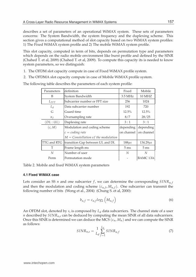
describes a set of parameters of an operational WiMAX system. These sets of parametersconcerns: The System Bandwidth, the system frequency and the duplexing scheme. Thissection gives a computational method of slot capacity based on two WiMAX system profiles:1) The Fixed WiMAX system profile and 2) The mobile WiMAX system profile.
This slot capacity, computed in term of bits, depends on permutation type and parameterswhich depends on the radio mobile environment like burst profile and defined by the SINR(Chahed T. et al, 2009) (Chahed T. et al, 2009). To compute this capacity its is needed to knowsystem parameters, so we distinguish:
1. The OFDM slot capacity compute in case of Fixed WiMAX profile system.
2. The OFDMA slot capacity compute in case of Mobile WiMAX profile system.
The following table describes the parameters of each system profile:
Parameters definition Fixed Mobile
B System Bandwidth 3.5 MHz 10 MHZ
LFFT Subcarrier number or FFT size 256 1024
Ld Data subcarrier number 192 720
G Guard time 12.5% 12.5%
n f Oversampling rate 8/7 28/25
(DL : UL) Duplexing rate 3 : 1 3 : 1
(c, M) Modulation and coding scheme depending depending
c = coding rate on channel on channel
M = Constellation o f the modulation
TTG and RTG transition Gap between UL and DL 188µs 134.29µs
T Frame length ms 5 ms 5 ms
N Number of user N N
Perm Permutation mode - BAMC 1X6
Table 2. Mobile and fixed WiMAX system parameters
4.1 Fixed WiMAX case
Lets consider an SS n and one subcarrier f , we can determine the corresponding SINRn, f
and then the modulation and coding scheme (cn, f , Mn, f ). One subcarrier can transmit thefollowing number of bits (Wong et al., 2004) (Chung S. et al, 2000):
bn, f = cn, f log2
(
Mn, f
)
(6)
An OFDM slot, denoted by s, is composed by Ld data subcarriers. The channel state of a usern described by SINRn,s can be deduced by computing the mean SINR of all data subcarriers.Once this SINR is determined we can deduce the MCS (cn, Mn) and we can compute the SINRas follows:
SINRn,s =1
Ld
Ld
∑f=1
SINRn, f (7)
157A Cross-Layer Radio Resource Management in WiMAX Systems
www.intechopen.com
12 Will-be-set-by-IN-TECH
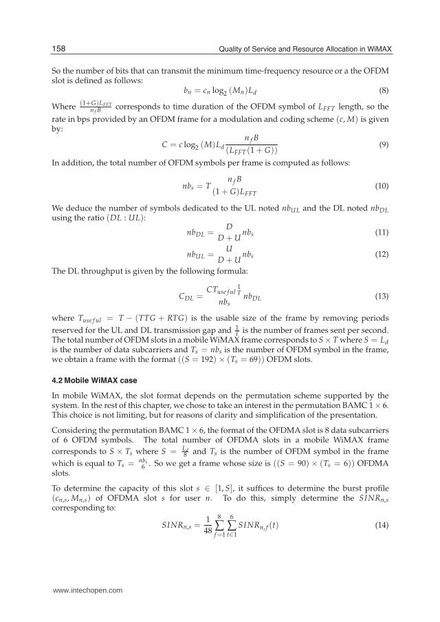
So the number of bits that can transmit the minimum time-frequency resource or a the OFDMslot is defined as follows:
bn = cn log2 (Mn)Ld (8)
Where(1+G)LFFT
n f B corresponds to time duration of the OFDM symbol of LFFT length, so the
rate in bps provided by an OFDM frame for a modulation and coding scheme (c, M) is givenby:
C = c log2 (M)Ld
n f B
(LFFT(1 + G))(9)
In addition, the total number of OFDM symbols per frame is computed as follows:
nbs = Tn f B
(1 + G)LFFT(10)
We deduce the number of symbols dedicated to the UL noted nbUL and the DL noted nbDL
using the ratio (DL : UL):
nbDL =D
D + Unbs (11)
nbUL =U
D + Unbs (12)
The DL throughput is given by the following formula:
CDL =CTuse f ul
1T
nbsnbDL (13)
where Tuse f ul = T − (TTG + RTG) is the usable size of the frame by removing periods
reserved for the UL and DL transmission gap and 1T is the number of frames sent per second.
The total number of OFDM slots in a mobile WiMAX frame corresponds to S× T where S = Ldis the number of data subcarriers and Ts = nbs is the number of OFDM symbol in the frame,we obtain a frame with the format ((S = 192)× (Ts = 69)) OFDM slots.
4.2 Mobile WiMAX case
In mobile WiMAX, the slot format depends on the permutation scheme supported by thesystem. In the rest of this chapter, we chose to take an interest in the permutation BAMC 1× 6.This choice is not limiting, but for reasons of clarity and simplification of the presentation.
Considering the permutation BAMC 1× 6, the format of the OFDMA slot is 8 data subcarriersof 6 OFDM symbols. The total number of OFDMA slots in a mobile WiMAX frame
corresponds to S × Ts where S = Ld8 and Ts is the number of OFDM symbol in the frame
which is equal to Ts = nbs6 . So we get a frame whose size is ((S = 90)× (Ts = 6)) OFDMA
slots.
To determine the capacity of this slot s ∈ [1, S], it suffices to determine the burst profile(cn,s, Mn,s) of OFDMA slot s for user n. To do this, simply determine the SINRn,s
corresponding to:
SINRn,s =1
48
8
∑f=1
6
∑t∈1
SINRn, f (t) (14)
158 Quality of Service and Resource Allocation in WiMAX
www.intechopen.com
A Cross-Layer Radio Resource Management in WiMAX Systems 13
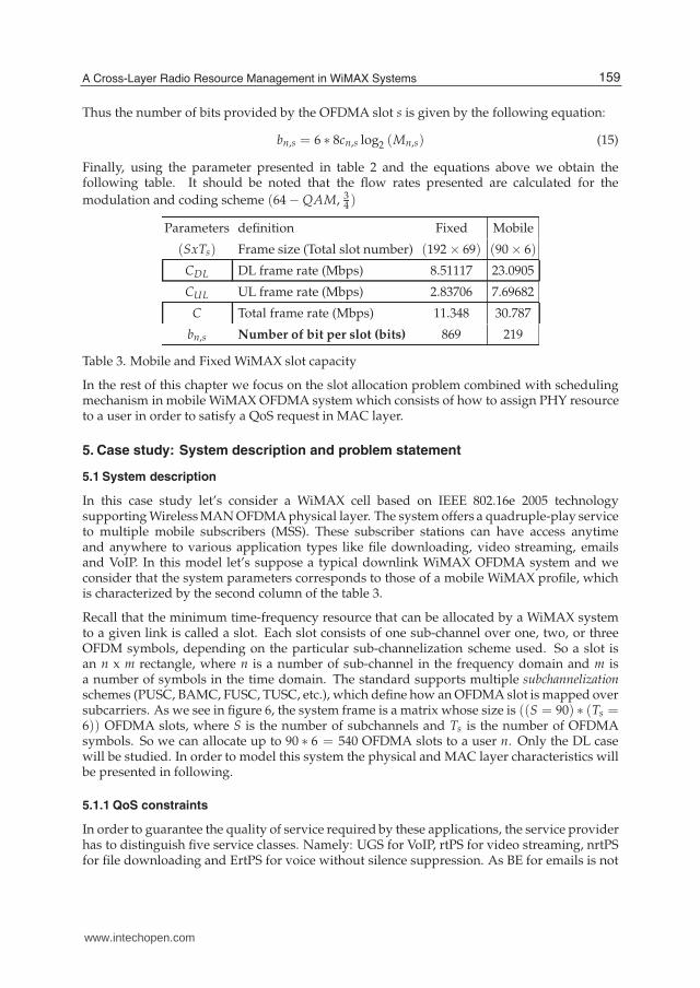
Thus the number of bits provided by the OFDMA slot s is given by the following equation:
bn,s = 6 ∗ 8cn,s log2 (Mn,s) (15)
Finally, using the parameter presented in table 2 and the equations above we obtain thefollowing table. It should be noted that the flow rates presented are calculated for the
modulation and coding scheme (64 − QAM, 34 )
Parameters definition Fixed Mobile
(SxTs) Frame size (Total slot number) (192 × 69) (90 × 6)
CDL DL frame rate (Mbps) 8.51117 23.0905
CUL UL frame rate (Mbps) 2.83706 7.69682
C Total frame rate (Mbps) 11.348 30.787
bn,s Number of bit per slot (bits) 869 219
Table 3. Mobile and Fixed WiMAX slot capacity
In the rest of this chapter we focus on the slot allocation problem combined with schedulingmechanism in mobile WiMAX OFDMA system which consists of how to assign PHY resourceto a user in order to satisfy a QoS request in MAC layer.
5. Case study: System description and problem statement
5.1 System description
In this case study let’s consider a WiMAX cell based on IEEE 802.16e 2005 technologysupporting Wireless MAN OFDMA physical layer. The system offers a quadruple-play serviceto multiple mobile subscribers (MSS). These subscriber stations can have access anytimeand anywhere to various application types like file downloading, video streaming, emailsand VoIP. In this model let’s suppose a typical downlink WiMAX OFDMA system and weconsider that the system parameters corresponds to those of a mobile WiMAX profile, whichis characterized by the second column of the table 3.
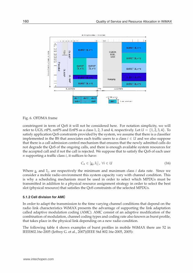
Recall that the minimum time-frequency resource that can be allocated by a WiMAX systemto a given link is called a slot. Each slot consists of one sub-channel over one, two, or threeOFDM symbols, depending on the particular sub-channelization scheme used. So a slot isan n x m rectangle, where n is a number of sub-channel in the frequency domain and m isa number of symbols in the time domain. The standard supports multiple subchannelizationschemes (PUSC, BAMC, FUSC, TUSC, etc.), which define how an OFDMA slot is mapped oversubcarriers. As we see in figure 6, the system frame is a matrix whose size is ((S = 90) ∗ (Ts =6)) OFDMA slots, where S is the number of subchannels and Ts is the number of OFDMAsymbols. So we can allocate up to 90 ∗ 6 = 540 OFDMA slots to a user n. Only the DL casewill be studied. In order to model this system the physical and MAC layer characteristics willbe presented in following.
5.1.1 QoS constraints
In order to guarantee the quality of service required by these applications, the service providerhas to distinguish five service classes. Namely: UGS for VoIP, rtPS for video streaming, nrtPSfor file downloading and ErtPS for voice without silence suppression. As BE for emails is not
159A Cross-Layer Radio Resource Management in WiMAX Systems
www.intechopen.com
14 Will-be-set-by-IN-TECH
Fig. 6. OFDMA frame
constringent in term of QoS it will not be considered here. For notation simplicity, we willrefer to UGS, rtPS, nrtPS and ErtPS as a class 1, 2, 3 and 4, respectively. Let U = {1, 2, 3, 4}. Tosatisfy application QoS constraints provided by the system, we assume that there is a classifierimplemented in the BS that associates each traffic users to a class i ∈ U and we also supposethat there is a call admission control mechanism that ensures that the newly admitted calls donot degrade the QoS of the ongoing calls, and there is enough available system resources forthe accepted call and if not the call is rejected. We suppose that to satisfy the QoS of each usern supporting a traffic class i, it suffices to have:
Cn ∈ [si, si] , ∀i ∈ U (16)
Where si and si, are respectively the minimum and maximum class i data rate. Since weconsider a mobile radio environment this system capacity vary with channel condition. Thisis why a scheduling mechanism must be used in order to select which MPDUs must betransmitted in addition to a physical resource assignment strategy in order to select the bestslot (physical resource) that satisfies the QoS constraints of the selected MPDUs.
5.1.2 Cell division for AMC
In order to adapt the transmission to the time varying channel conditions that depend on theradio link characteristics WiMAX presents the advantage of supporting the link adaptationcalled adaptive modulation coding (AMC). AMC consist of an adaptive modification of thecombination of modulation, channel coding types and coding rate also known as burst profile,that takes place in the physical link depending on a new radio condition.
The following table 4 shows examples of burst profiles in mobile WiMAX there are 52 inIEEE802.16e-2005 (Jeffrey G. et al., 2007)(IEEE Std 802.16e-2005, 2005):
160 Quality of Service and Resource Allocation in WiMAX
www.intechopen.com
A Cross-Layer Radio Resource Management in WiMAX Systems 15
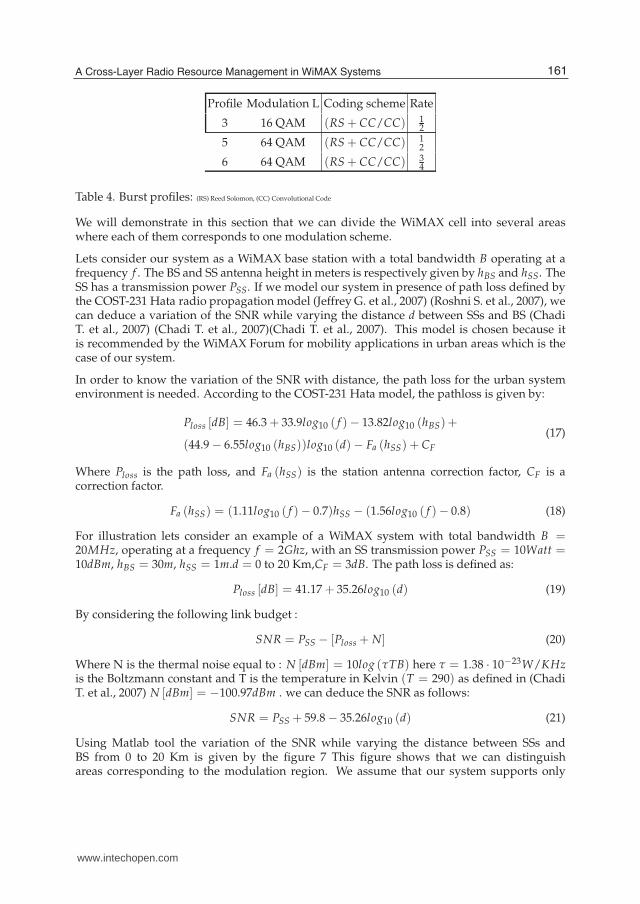
Profile Modulation L Coding scheme Rate
3 16 QAM (RS + CC/CC) 12
5 64 QAM (RS + CC/CC) 12
6 64 QAM (RS + CC/CC) 34
Table 4. Burst profiles: (RS) Reed Solomon, (CC) Convolutional Code
We will demonstrate in this section that we can divide the WiMAX cell into several areaswhere each of them corresponds to one modulation scheme.
Lets consider our system as a WiMAX base station with a total bandwidth B operating at afrequency f . The BS and SS antenna height in meters is respectively given by hBS and hSS. TheSS has a transmission power PSS. If we model our system in presence of path loss defined bythe COST-231 Hata radio propagation model (Jeffrey G. et al., 2007) (Roshni S. et al., 2007), wecan deduce a variation of the SNR while varying the distance d between SSs and BS (ChadiT. et al., 2007) (Chadi T. et al., 2007)(Chadi T. et al., 2007). This model is chosen because itis recommended by the WiMAX Forum for mobility applications in urban areas which is thecase of our system.
In order to know the variation of the SNR with distance, the path loss for the urban systemenvironment is needed. According to the COST-231 Hata model, the pathloss is given by:
Ploss [dB] = 46.3 + 33.9log10 ( f )− 13.82log10 (hBS) +
(44.9 − 6.55log10 (hBS))log10 (d)− Fa (hSS) + CF
(17)
Where Ploss is the path loss, and Fa (hSS) is the station antenna correction factor, CF is acorrection factor.
Fa (hSS) = (1.11log10 ( f )− 0.7)hSS − (1.56log10 ( f )− 0.8) (18)
For illustration lets consider an example of a WiMAX system with total bandwidth B =20MHz, operating at a frequency f = 2Ghz, with an SS transmission power PSS = 10Watt =10dBm, hBS = 30m, hSS = 1m.d = 0 to 20 Km,CF = 3dB. The path loss is defined as:
Ploss [dB] = 41.17 + 35.26log10 (d) (19)
By considering the following link budget :
SNR = PSS − [Ploss + N] (20)
Where N is the thermal noise equal to : N [dBm] = 10log (τTB) here τ = 1.38 · 10−23W/KHzis the Boltzmann constant and T is the temperature in Kelvin (T = 290) as defined in (ChadiT. et al., 2007) N [dBm] = −100.97dBm . we can deduce the SNR as follows:
SNR = PSS + 59.8 − 35.26log10 (d) (21)
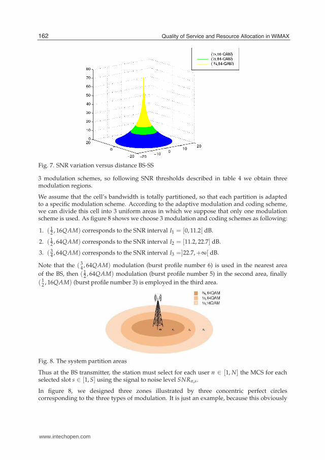
Using Matlab tool the variation of the SNR while varying the distance between SSs andBS from 0 to 20 Km is given by the figure 7 This figure shows that we can distinguishareas corresponding to the modulation region. We assume that our system supports only
161A Cross-Layer Radio Resource Management in WiMAX Systems
www.intechopen.com
16 Will-be-set-by-IN-TECH
Fig. 7. SNR variation versus distance BS-SS
3 modulation schemes, so following SNR thresholds described in table 4 we obtain threemodulation regions.
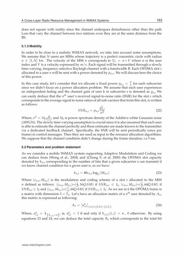
We assume that the cell’s bandwidth is totally partitioned, so that each partition is adaptedto a specific modulation scheme. According to the adaptive modulation and coding scheme,we can divide this cell into 3 uniform areas in which we suppose that only one modulationscheme is used. As figure 8 shows we choose 3 modulation and coding schemes as following:
1. ( 12 , 16QAM) corresponds to the SNR interval I1 = [0, 11.2[ dB.
2. ( 12 , 64QAM) corresponds to the SNR interval I2 = [11.2, 22.7] dB.
3. ( 34 , 64QAM) corresponds to the SNR interval I3 =]22.7,+∞[ dB.
Note that the ( 34 , 64QAM) modulation (burst profile number 6) is used in the nearest area
of the BS, then ( 12 , 64QAM) modulation (burst profile number 5) in the second area, finally
( 12 , 16QAM) (burst profile number 3) is employed in the third area.
Fig. 8. The system partition areas
Thus at the BS transmitter, the station must select for each user n ∈ [1, N] the MCS for eachselected slot s ∈ [1, S] using the signal to noise level SNRn,s.
In figure 8, we designed three zones illustrated by three concentric perfect circlescorresponding to the three types of modulation. It is just an example, because this obviously
162 Quality of Service and Resource Allocation in WiMAX
www.intechopen.com
A Cross-Layer Radio Resource Management in WiMAX Systems 17
does not square with reality since the channel undergoes disturbances other than the pathLoss that vary the channel between two stations even they are at the same distance from theBS.
5.1.3 Mobility
In order to be close to a realistic WiMAX network, we take into account some assumptions.We assume that N users are MSSs whose trajectory is a perfect concentric circle with radiusn ∈ [1, N] km. The velocity of the MSS n corresponds to Vn = n ∗ V where n is the userindex and V is a velocity expressed by m/s. Each signal will be transmitted through a slowlytime-varying, frequency-selective Rayleigh channel with a bandwidth B. Each OFDMA slot sallocated to a user n will be sent with a power denoted by pn,s. We will discuss here the choiceof this power.
In this case study, let’s consider that we allocate a fixed power pk,s = PS for each subcarrier
since we didn’t focus on a power allocation problem. We assume that each user experiencesan independent fading and the channel gain of user k in subcarrier s is denoted as gk,s We
can easily deduce that the nth user’s received signal-to-noise ratio (SNR) for the slot s whichcorresponds to the average signal to noise ratios of all sub-carriers that form this slot, is writtenas follows:
SNRn,s = pn,sg2
n,s
σ2(22)
Where, σ2 = N0B
LFFTand N0 is power spectrum density of the Additive white Gaussian noise
(AWGN). The slowly time-varying assumption is crucial since it is also assumed that each useris able to estimate the channel perfectly and these estimates are made known to the transmittervia a dedicated feedback channel. Specifically, the SNR will be sent periodically (once perframe) in control messages. Then they are used as input to the resource allocation algorithms.We suppose that the channel condition didn’t change during the frame duration, i.e 5 ms.
5.2 Parameters and problem statement
As we consider a mobile WiMAX system supporting Adaptive Modulation and Coding wecan deduce from (Wong et al., 2004) and (Chung S. et al, 2000) the OFDMA slot capacitydenoted by bn,s corresponding to the number of bits that a given subcarrier s can transmit ifwe know channel condition for a given user n, so we have:
bn,s = 48cn,s log2 (Mn,s) (23)
Where (cn,s, Mn,s) is the modulation and coding scheme of a slot s allocated to the MSS
n defined as follows: (cn,s, Mn,s)=(12 , 16QAM) if SNRn,s ∈ I1, (cn,s, Mn,s)=(
12 , 64QAM) if
SNRn,s ∈ I2 and (cn,s, Mn,s)=(34 , 64QAM) if SNRn,s ∈ I3. As we see in 6 the OFDMA frame is
a matrix with dimension S × TS. Let’s have an allocation matrix of a nth user denoted by An,this matrix is expressed as following:
An =[
ans,t
]
(s,t)∈{1,S}×{1,Ts}(24)
Where, ans,t = 1{1(s,t)=n}, ie, an
s,t = 1 if and only if 1(s,t)(i, j) = n , 0 otherwise. By using
equations 23 and 24, we can deduce the total capacity Bn which corresponds to the total bit
163A Cross-Layer Radio Resource Management in WiMAX Systems
www.intechopen.com
18 Will-be-set-by-IN-TECH
number provided to the user n after a slot allocation following the allocation matrix An:
Bn =S
∑s=1
Ts
∑t=1
ans,tbn,s (25)
The total system capacity if the call admission controll mechanism accept N MSSs is:
C =N
∑n=1
Cn =n f B
(1 + G)LFFT
N
∑n=1
S
∑s=1
Ts
∑t=1
ans,tcn,s log2 (Mn,s) (26)
It is clear that the choice of the matrix allocation is crucial for the optimal use of resources. Theaim of this case study is to present an efficient cross-layer resource assignment strategy thattakes into account two aspects: 1)the varying channel condition and 2) the QoS constraints ofuser’s MPDUs scheduled to be transmitted into the physical frame.
Problems related to resource allocation and power assignment aim to solve the followingmutli-constraints optimization problem (Wong et al., 2004) (Cheong et al., 1999):
Problem 1 Slot allocation problem
maximize: maxpn,s,at,s
C
subject to:
C1 :N
∑n=1
S
∑s=1
Ts
∑t=1
at,s pn,s ≤ Ptotal
C2 : Cn ∈ [si, si] , ∀i ∈ U
C3 : pn,s ≥ 0, ∀(n, s) ∈ [1, N]X[1, S]
C4 : at,s ∈ 0, 1, ∀(s, t) ∈ [1, S]X[1, Ts]
Where C1 corresponds to the power constraint, C2 corresponds to the QoS constraint discribedin 16 , C3 and C4 ensure the correct values for the power and the subcarrier allocation matrixelement, respectively.
This problem is NP-hard problem (Mathias et al, 2007) and was often treated by taking intoaccount only the physical layer without respecting constraints related to quality of service.Generally, this problem is split into two subproblems: subproblem (1) consists on powerassignment problem, where only the power will be considered as the variable of the problem,and subproblem (2) consists on maximizing the instantaneous system capacity C once thepower is allocated. In our case study, we will not consider power allocation issues and we willassume that all subcarriers have the same transmit power, i.e, pn,s = p∀(n, s) ∈ [1, N]X[1, S].The SNR variation is only related to the channel variation. So our problem statement is thefollowing, if we consider the OFDMA frame is like a puzzle game with slots as game pieces,where the game rule is that these slots must be allocated to each MSSs according to theirdemand. The difficulty of this game is that of the slot capacity is variable and depends on thechannel state. In the next we answer the two questions: Which MPDUs to serve? and whichslot to assign to satisfy the bandwidth request of the selected MPDUs? In the next section, wepropose solutions to both questions.
164 Quality of Service and Resource Allocation in WiMAX
www.intechopen.com
A Cross-Layer Radio Resource Management in WiMAX Systems 19
6. Solutions
In order to answer to questions asked in the previous section, one solution is to combinescheduling mechanism with a slots mapping while taking into account three aspects: 1) TheQoS constraints of each traffic class, 2) the specific features of the system like Permutationscheme and 3) OFDMA access technology and the radio channel variation which results inthe choice of modulation and therefore the variation of the allocated slots capacity.
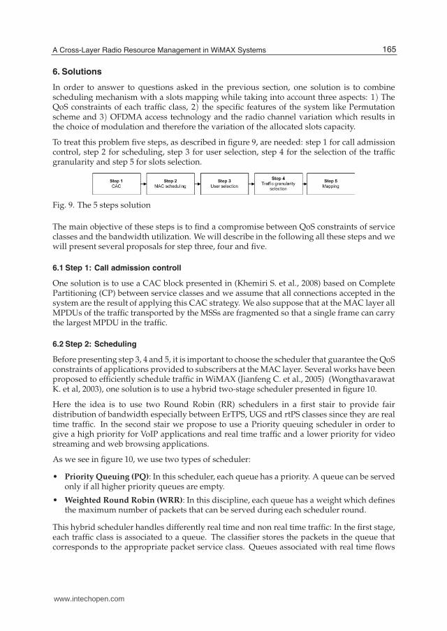
To treat this problem five steps, as described in figure 9, are needed: step 1 for call admissioncontrol, step 2 for scheduling, step 3 for user selection, step 4 for the selection of the trafficgranularity and step 5 for slots selection.
Fig. 9. The 5 steps solution
The main objective of these steps is to find a compromise between QoS constraints of serviceclasses and the bandwidth utilization. We will describe in the following all these steps and wewill present several proposals for step three, four and five.
6.1 Step 1: Call admission controll
One solution is to use a CAC block presented in (Khemiri S. et al., 2008) based on CompletePartitioning (CP) between service classes and we assume that all connections accepted in thesystem are the result of applying this CAC strategy. We also suppose that at the MAC layer allMPDUs of the traffic transported by the MSSs are fragmented so that a single frame can carrythe largest MPDU in the traffic.
6.2 Step 2: Scheduling
Before presenting step 3, 4 and 5, it is important to choose the scheduler that guarantee the QoSconstraints of applications provided to subscribers at the MAC layer. Several works have beenproposed to efficiently schedule traffic in WiMAX (Jianfeng C. et al., 2005) (WongthavarawatK. et al, 2003), one solution is to use a hybrid two-stage scheduler presented in figure 10.
Here the idea is to use two Round Robin (RR) schedulers in a first stair to provide fairdistribution of bandwidth especially between ErTPS, UGS and rtPS classes since they are realtime traffic. In the second stair we propose to use a Priority queuing scheduler in order togive a high priority for VoIP applications and real time traffic and a lower priority for videostreaming and web browsing applications.
As we see in figure 10, we use two types of scheduler:
• Priority Queuing (PQ): In this scheduler, each queue has a priority. A queue can be servedonly if all higher priority queues are empty.
• Weighted Round Robin (WRR): In this discipline, each queue has a weight which definesthe maximum number of packets that can be served during each scheduler round.
This hybrid scheduler handles differently real time and non real time traffic: In the first stage,each traffic class is associated to a queue. The classifier stores the packets in the queue thatcorresponds to the appropriate packet service class. Queues associated with real time flows
165A Cross-Layer Radio Resource Management in WiMAX Systems
www.intechopen.com
20 Will-be-set-by-IN-TECH
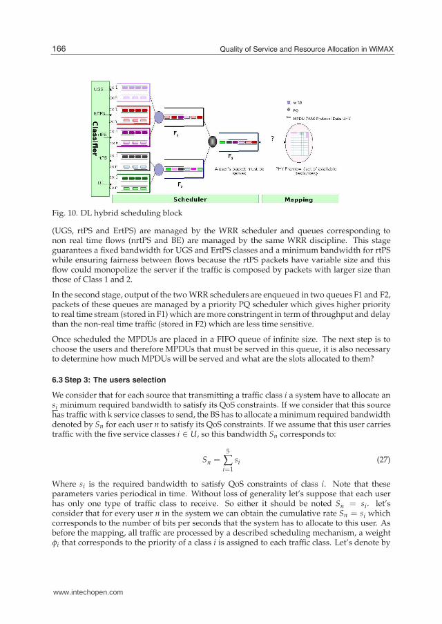
Fig. 10. DL hybrid scheduling block
(UGS, rtPS and ErtPS) are managed by the WRR scheduler and queues corresponding tonon real time flows (nrtPS and BE) are managed by the same WRR discipline. This stageguarantees a fixed bandwidth for UGS and ErtPS classes and a minimum bandwidth for rtPSwhile ensuring fairness between flows because the rtPS packets have variable size and thisflow could monopolize the server if the traffic is composed by packets with larger size thanthose of Class 1 and 2.
In the second stage, output of the two WRR schedulers are enqueued in two queues F1 and F2,packets of these queues are managed by a priority PQ scheduler which gives higher priorityto real time stream (stored in F1) which are more constringent in term of throughput and delaythan the non-real time traffic (stored in F2) which are less time sensitive.
Once scheduled the MPDUs are placed in a FIFO queue of infinite size. The next step is tochoose the users and therefore MPDUs that must be served in this queue, it is also necessaryto determine how much MPDUs will be served and what are the slots allocated to them?
6.3 Step 3: The users selection
We consider that for each source that transmitting a traffic class i a system have to allocate ansi minimum required bandwidth to satisfy its QoS constraints. If we consider that this sourcehas traffic with k service classes to send, the BS has to allocate a minimum required bandwidthdenoted by Sn for each user n to satisfy its QoS constraints. If we assume that this user carriestraffic with the five service classes i ∈ U, so this bandwidth Sn corresponds to:
Sn =5
∑i=1
si (27)
Where si is the required bandwidth to satisfy QoS constraints of class i. Note that theseparameters varies periodical in time. Without loss of generality let’s suppose that each userhas only one type of traffic class to receive. So either it should be noted Sn = si. let’sconsider that for every user n in the system we can obtain the cumulative rate Sn = si whichcorresponds to the number of bits per seconds that the system has to allocate to this user. Asbefore the mapping, all traffic are processed by a described scheduling mechanism, a weightφi that corresponds to the priority of a class i is assigned to each traffic class. Let’s denote by
166 Quality of Service and Resource Allocation in WiMAX
www.intechopen.com
A Cross-Layer Radio Resource Management in WiMAX Systems 21
Qi the following satisfaction parameter:
Qi = φisi
si(28)
This parameter will serve to select users that are not satisfied in order to serve them first. Theuser satisfaction is defined as follows: All users that verifying the condition si ≤ si, that wecall QoS satisfaction condition (QSC), are called not satisfied users . To determine what userto choose, the algorithm selects the user that is least satisfied i.e the one that checks the leastsatisfaction condition QSC and thus satisfies the equation 29:
n = arg minu∈N
Qu (29)
If there are many that corresponds to the minimum several solutions are used: one solutionis to choose randomly one of them or the user that request the maximum of bandwidth (s(i))
or the user that corresponds to the maximum of the value(
si − si
)
otherwise select the user
that it has the prior service class (UGS > ErtPS > rtPS > nrtPS > BE).
In what follows, for simplicity the first option is used.
6.4 Step 4: The selection of the traffic granularity
Once the user is selected to be served, the next step is to know how much user MPDUs it willbe served? Three solutions to choose the amount of MPDUs to be served are presented asfollows:
1. All user MPDUs: All MPDUs belonging to the selected user that are in the queue will beserved. The disadvantage is that a user could monopolize physical resources. We denotethis method a TP strategy for Total user packets.
2. MPDUs by MPDUs: In this proposal, we process only one MPDUs by selected user. Onceslots are allocated to it, we move to the next user. This avoids the disadvantage of the firstproposal. We denote this method PP for Packet Per Packet.
3. Only the number of bits needed is treated in order to reduce the user delay: In this case,each user has a credit we will denote Creditn(t) which corresponds to the amount ofbandwidth allocated until time t, ( t is a multiple of the duration of the frame (t = xT, T =Frame duration)). This credit will be updated whenever the system allocates one or moreslots by adding the amount of bits provided by each allocated slot. At time t, to guaranteethe QoS constraints of the user n that receiving a traffic class i, the user will be allocated atleast Bn = xsi. Bn is the number of bits that should be served to ensure the user’s request.We can then define the delay or retard as follows:
Retardn(t) = Bn − Creditn(t) (30)
Two cases arise:
• If Retardn(t) > 0, i.e what we need to allocate to the user, is more than what wehave allowed him, in this case the user is in retard and we must serve more than theRetardn(t) to retrieve the user n retard .
• If Retardn(t) ≤ 0, in this case the user is not in retard and we serve only one MPDU ofthis user.
167A Cross-Layer Radio Resource Management in WiMAX Systems
www.intechopen.com
22 Will-be-set-by-IN-TECH
Lets note this strategy as RR for Retrieve Retard.
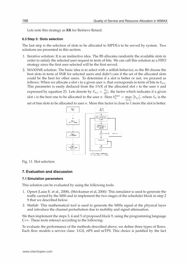
6.5 Step 5: Slots selection
The last step is the selection of slots to be allocated to MPDUs to be served by system. Twosolutions are presented in this section:
1. Iterative solution: It is an instinctive idea. The BS allocates randomly the available slots inorder to satisfy the selected user request in term of bits. We can call this solution as a FIFOstrategy since the first user selected will be the first served.
2. MAXSNR solution: The basic idea is to select with a selfish behavior, so the BS choose thebest slots in term of SNR for selected users and didn’t care if the set of the allocated slotscould be the best for other users. To determine if a slot is better or not, we proceed asfollows: When we allocate a slot s to a given user n, that corresponds in term of bits to bn,s.This parameter is easily deduced from the SNR of the allocated slot s to the user n and
expressed by equation 23. Lets denote by Fn,s =bn,s
bmaxn
the factor which indicates if a given
slot s is the best one to be allocated to the user n. Here bmaxn = max
l∈Sn
[
bn,l
]
, where Sn is the
set of free slots to be allocated to user n. More this factor is close to 1 more the slot is better.
Fig. 11. Slot selection
7. Evaluation and discussion
7.1 Simulation parameters
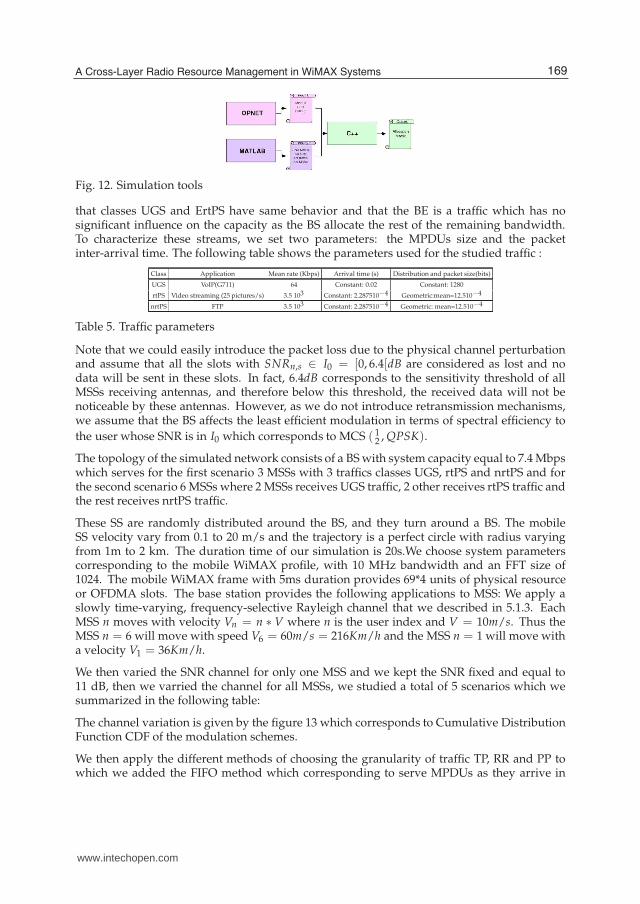
This solution can be evaluated by using the following tools:
1. Opnet (Laias E. et al., 2008), (Shivkumar et al, 2000): This simulator is used to generate thetraffic carried by the MSS and to implement the two stages of the scheduler block in step 29 that we described below.
2. Matlab: This mathematical tool is used to generate the MSSs signal at the physical layerand introduce the channel perturbation due to mobility and signal attenuation.
We then implement the steps 3, 4 and 5 of proposed block 9, using the programming languageC++. These tools interact according to the following:
To evaluate the performance of the methods described above, we define three types of flows.Each flow models a service class: UGS, rtPS and nrTPS. This choice is justified by the fact
168 Quality of Service and Resource Allocation in WiMAX
www.intechopen.com
A Cross-Layer Radio Resource Management in WiMAX Systems 23
Fig. 12. Simulation tools
that classes UGS and ErtPS have same behavior and that the BE is a traffic which has nosignificant influence on the capacity as the BS allocate the rest of the remaining bandwidth.To characterize these streams, we set two parameters: the MPDUs size and the packetinter-arrival time. The following table shows the parameters used for the studied traffic :
Class Application Mean rate (Kbps) Arrival time (s) Distribution and packet size(bits)
UGS VoIP(G711) 64 Constant: 0.02 Constant: 1280
rtPS Video streaming (25 pictures/s) 3.5 103 Constant: 2.287510−4 Geometric:mean=12.510−4
nrtPS FTP 3.5 103 Constant: 2.287510−4 Geometric: mean=12.510−4
Table 5. Traffic parameters
Note that we could easily introduce the packet loss due to the physical channel perturbationand assume that all the slots with SNRn,s ∈ I0 = [0, 6.4[dB are considered as lost and nodata will be sent in these slots. In fact, 6.4dB corresponds to the sensitivity threshold of allMSSs receiving antennas, and therefore below this threshold, the received data will not benoticeable by these antennas. However, as we do not introduce retransmission mechanisms,we assume that the BS affects the least efficient modulation in terms of spectral efficiency to
the user whose SNR is in I0 which corresponds to MCS ( 12 , QPSK).
The topology of the simulated network consists of a BS with system capacity equal to 7.4 Mbpswhich serves for the first scenario 3 MSSs with 3 traffics classes UGS, rtPS and nrtPS and forthe second scenario 6 MSSs where 2 MSSs receives UGS traffic, 2 other receives rtPS traffic andthe rest receives nrtPS traffic.
These SS are randomly distributed around the BS, and they turn around a BS. The mobileSS velocity vary from 0.1 to 20 m/s and the trajectory is a perfect circle with radius varyingfrom 1m to 2 km. The duration time of our simulation is 20s.We choose system parameterscorresponding to the mobile WiMAX profile, with 10 MHz bandwidth and an FFT size of1024. The mobile WiMAX frame with 5ms duration provides 69*4 units of physical resourceor OFDMA slots. The base station provides the following applications to MSS: We apply aslowly time-varying, frequency-selective Rayleigh channel that we described in 5.1.3. EachMSS n moves with velocity Vn = n ∗ V where n is the user index and V = 10m/s. Thus theMSS n = 6 will move with speed V6 = 60m/s = 216Km/h and the MSS n = 1 will move witha velocity V1 = 36Km/h.
We then varied the SNR channel for only one MSS and we kept the SNR fixed and equal to11 dB, then we varried the channel for all MSSs, we studied a total of 5 scenarios which wesummarized in the following table:
The channel variation is given by the figure 13 which corresponds to Cumulative DistributionFunction CDF of the modulation schemes.
We then apply the different methods of choosing the granularity of traffic TP, RR and PP towhich we added the FIFO method which corresponding to serve MPDUs as they arrive in
169A Cross-Layer Radio Resource Management in WiMAX Systems
www.intechopen.com
24 Will-be-set-by-IN-TECH
scenario: 6 MSSs
Channel state UGS(1) UGS(2) rtPS(1) rtPS(2) nrtPS(1) nrtPS(2)
1 F F F F F F
2 P P P P P P
3 P F F F F F
4 F F P F F F
5 F F F F P F
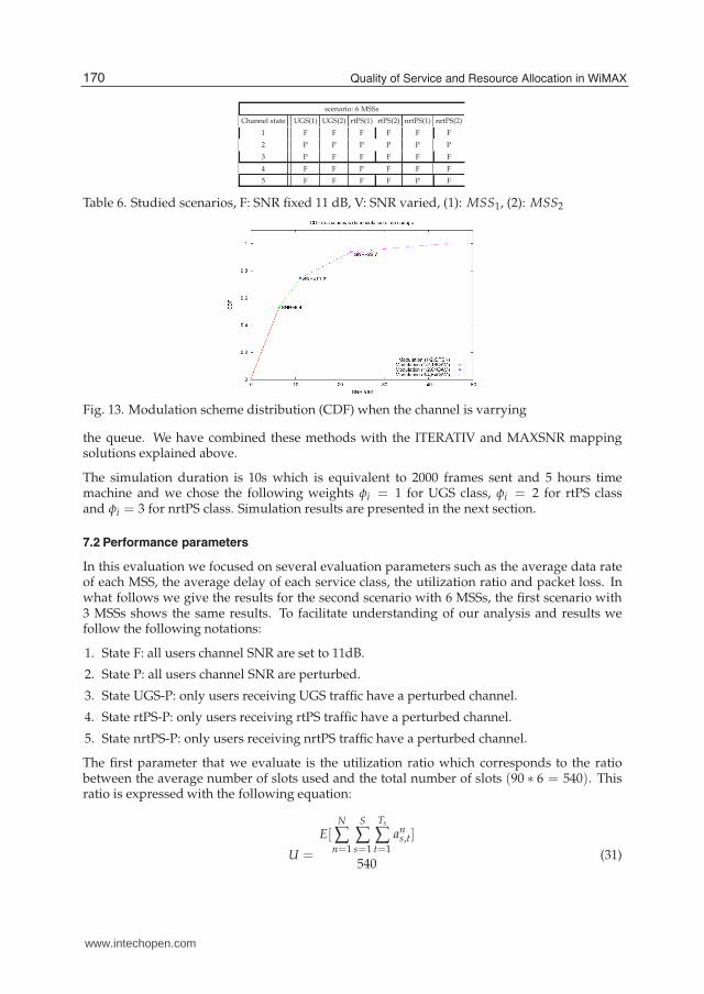
Table 6. Studied scenarios, F: SNR fixed 11 dB, V: SNR varied, (1): MSS1, (2): MSS2
Fig. 13. Modulation scheme distribution (CDF) when the channel is varrying
the queue. We have combined these methods with the ITERATIV and MAXSNR mappingsolutions explained above.
The simulation duration is 10s which is equivalent to 2000 frames sent and 5 hours timemachine and we chose the following weights φi = 1 for UGS class, φi = 2 for rtPS classand φi = 3 for nrtPS class. Simulation results are presented in the next section.
7.2 Performance parameters
In this evaluation we focused on several evaluation parameters such as the average data rateof each MSS, the average delay of each service class, the utilization ratio and packet loss. Inwhat follows we give the results for the second scenario with 6 MSSs, the first scenario with3 MSSs shows the same results. To facilitate understanding of our analysis and results wefollow the following notations:
1. State F: all users channel SNR are set to 11dB.
2. State P: all users channel SNR are perturbed.
3. State UGS-P: only users receiving UGS traffic have a perturbed channel.
4. State rtPS-P: only users receiving rtPS traffic have a perturbed channel.
5. State nrtPS-P: only users receiving nrtPS traffic have a perturbed channel.
The first parameter that we evaluate is the utilization ratio which corresponds to the ratiobetween the average number of slots used and the total number of slots (90 ∗ 6 = 540). Thisratio is expressed with the following equation:
U =
E[N
∑n=1
S
∑s=1
Ts
∑t=1
ans,t]
540(31)
170 Quality of Service and Resource Allocation in WiMAX
www.intechopen.com
A Cross-Layer Radio Resource Management in WiMAX Systems 25
We are also interested in the average delay per class i per user expressed as follows:
Di = E[Ts,i − Tg,i] (32)
Where Ts,i is the service time and Tg,i is the MPDUs generation time for class i. Finally, it isalso important to estimate the MPDUs loss which corresponds to those that they could not beserved on time, this loss is expressed as the mean number of lost packets per user per frame,denoted Lossi(t). We assume that a UGS or rtPS packet is lost only if it waits longer than 40ms in the queue before to be served.
Lossi(t) =
∑di>=40
nMPDUS,di(t)
2000(33)
nMPDUS,di(t) is the number of MPDUs of class i that should b served at time t and the waiting
time is di = Ts,i − Tg,i.
7.3 Analysis
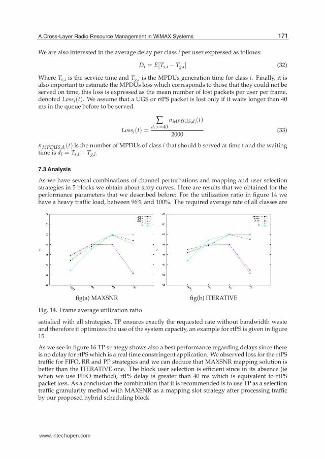
As we have several combinations of channel perturbations and mapping and user selectionstrategies in 5 blocks we obtain about sixty curves. Here are results that we obtained for theperformance parameters that we described before: For the utilization ratio in figure 14 wehave a heavy traffic load, between 96% and 100%. The required average rate of all classes are
fig(a) MAXSNR fig(b) ITERATIVE
Fig. 14. Frame average utilization ratio
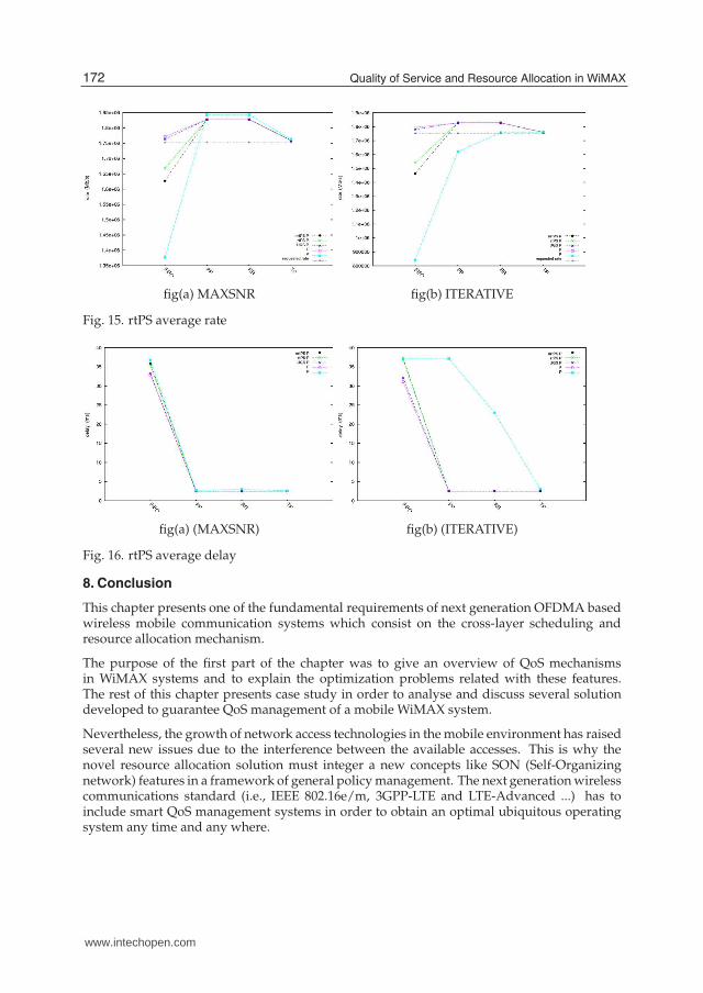
satisfied with all strategies, TP ensures exactly the requested rate without bandwidth wasteand therefore it optimizes the use of the system capacity, an example for rtPS is given in figure15.
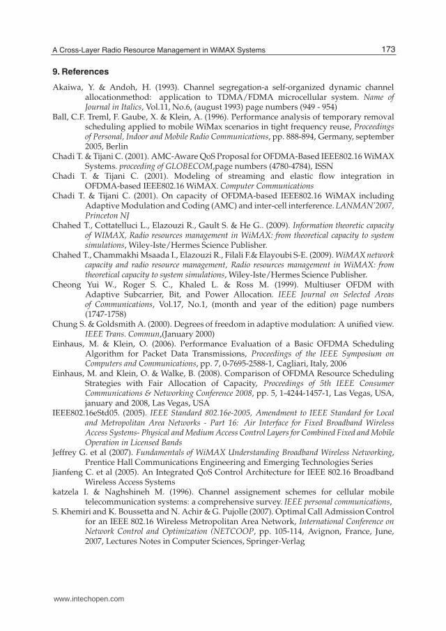
As we see in figure 16 TP strategy shows also a best performance regarding delays since thereis no delay for rtPS which is a real time constringent application. We observed loss for the rtPStraffic for FIFO, RR and PP strategies and we can deduce that MAXSNR mapping solution isbetter than the ITERATIVE one. The block user selection is efficient since in its absence (iewhen we use FIFO method), rtPS delay is greater than 40 ms which is equivalent to rtPSpacket loss. As a conclusion the combination that it is recommended is to use TP as a selectiontraffic granularity method with MAXSNR as a mapping slot strategy after processing trafficby our proposed hybrid scheduling block.
171A Cross-Layer Radio Resource Management in WiMAX Systems
www.intechopen.com
26 Will-be-set-by-IN-TECH
fig(a) MAXSNR fig(b) ITERATIVE
Fig. 15. rtPS average rate
fig(a) (MAXSNR) fig(b) (ITERATIVE)
Fig. 16. rtPS average delay
8. Conclusion
This chapter presents one of the fundamental requirements of next generation OFDMA basedwireless mobile communication systems which consist on the cross-layer scheduling andresource allocation mechanism.
The purpose of the first part of the chapter was to give an overview of QoS mechanismsin WiMAX systems and to explain the optimization problems related with these features.The rest of this chapter presents case study in order to analyse and discuss several solutiondeveloped to guarantee QoS management of a mobile WiMAX system.
Nevertheless, the growth of network access technologies in the mobile environment has raisedseveral new issues due to the interference between the available accesses. This is why thenovel resource allocation solution must integer a new concepts like SON (Self-Organizingnetwork) features in a framework of general policy management. The next generation wirelesscommunications standard (i.e., IEEE 802.16e/m, 3GPP-LTE and LTE-Advanced ...) has toinclude smart QoS management systems in order to obtain an optimal ubiquitous operatingsystem any time and any where.
172 Quality of Service and Resource Allocation in WiMAX
www.intechopen.com
A Cross-Layer Radio Resource Management in WiMAX Systems 27
9. References
Akaiwa, Y. & Andoh, H. (1993). Channel segregation-a self-organized dynamic channelallocationmethod: application to TDMA/FDMA microcellular system. Name ofJournal in Italics, Vol.11, No.6, (august 1993) page numbers (949 - 954)
Ball, C.F. Treml, F. Gaube, X. & Klein, A. (1996). Performance analysis of temporary removalscheduling applied to mobile WiMax scenarios in tight frequency reuse, Proceedingsof Personal, Indoor and Mobile Radio Communications, pp. 888-894, Germany, september2005, Berlin
Chadi T. & Tijani C. (2001). AMC-Aware QoS Proposal for OFDMA-Based IEEE802.16 WiMAXSystems. proceeding of GLOBECOM,page numbers (4780-4784), ISSN
Chadi T. & Tijani C. (2001). Modeling of streaming and elastic flow integration inOFDMA-based IEEE802.16 WiMAX. Computer Communications
Chadi T. & Tijani C. (2001). On capacity of OFDMA-based IEEE802.16 WiMAX includingAdaptive Modulation and Coding (AMC) and inter-cell interference. LANMAN’2007,Princeton NJ
Chahed T., Cottatelluci L., Elazouzi R., Gault S. & He G.. (2009). Information theoretic capacityof WIMAX, Radio resources management in WiMAX: from theoretical capacity to systemsimulations, Wiley-Iste/Hermes Science Publisher.
Chahed T., Chammakhi Msaada I., Elazouzi R., Filali F.& Elayoubi S-E. (2009). WiMAX networkcapacity and radio resource management, Radio resources management in WiMAX: fromtheoretical capacity to system simulations, Wiley-Iste/Hermes Science Publisher.
Cheong Yui W., Roger S. C., Khaled L. & Ross M. (1999). Multiuser OFDM withAdaptive Subcarrier, Bit, and Power Allocation. IEEE Journal on Selected Areasof Communications, Vol.17, No.1, (month and year of the edition) page numbers(1747-1758)
Chung S. & Goldsmith A. (2000). Degrees of freedom in adaptive modulation: A unified view.IEEE Trans. Commun,(January 2000)
Einhaus, M. & Klein, O. (2006). Performance Evaluation of a Basic OFDMA SchedulingAlgorithm for Packet Data Transmissions, Proceedings of the IEEE Symposium onComputers and Communications, pp. 7, 0-7695-2588-1, Cagliari, Italy, 2006
Einhaus, M. and Klein, O. & Walke, B. (2008). Comparison of OFDMA Resource SchedulingStrategies with Fair Allocation of Capacity, Proceedings of 5th IEEE ConsumerCommunications & Networking Conference 2008, pp. 5, 1-4244-1457-1, Las Vegas, USA,january and 2008, Las Vegas, USA
IEEE802.16eStd05. (2005). IEEE Standard 802.16e-2005, Amendment to IEEE Standard for Localand Metropolitan Area Networks - Part 16: Air Interface for Fixed Broadband WirelessAccess Systems- Physical and Medium Access Control Layers for Combined Fixed and MobileOperation in Licensed Bands
Jeffrey G. et al (2007). Fundamentals of WiMAX Understanding Broadband Wireless Networking,Prentice Hall Communications Engineering and Emerging Technologies Series
Jianfeng C. et al (2005). An Integrated QoS Control Architecture for IEEE 802.16 BroadbandWireless Access Systems
katzela I. & Naghshineh M. (1996). Channel assignement schemes for cellular mobiletelecommunication systems: a comprehensive survey. IEEE personal communications,
S. Khemiri and K. Boussetta and N. Achir & G. Pujolle (2007). Optimal Call Admission Controlfor an IEEE 802.16 Wireless Metropolitan Area Network, International Conference onNetwork Control and Optimization (NETCOOP, pp. 105-114, Avignon, France, June,2007, Lectures Notes in Computer Sciences, Springer-Verlag
173A Cross-Layer Radio Resource Management in WiMAX Systems
www.intechopen.com
28 Will-be-set-by-IN-TECH
S. Khemiri, K. Boussetta and N. Achir & G. Pujolle (2007). Bandwidth partitioning for mobileWiMAX service provisioning, Proceedings of IFFIP Wireless Days, pp. 20-26, Dubai,November 2008, IEEExplorer
S. Khemiri and K. Boussetta and N. Achir & G. Pujolle (2007). A combined MAC and Physicalresource allocation mechanism in IEEE 802.16e networks, Proceedings of VTC’2010,pp. 6-10, 15502252, Taipei, may 2010, IEEExplorer
Laias E., Awan I. & Chan P.M. (2008). An Integrated Uplink Scheduler in IEEE 802.16,Proceedings of Second UKSIM European Symposium on Computer Modeling andSimulation, 2008. EMS ’08, pp. 518-523, sep 2008
Mathias Bohge and James Gross and Adam Wolisz and Tkn Group and Tu Berlin and MichaelMeyer and Ericsson Gmbh (2007). Dynamic Resource Allocation in OFDM Systems:An Overview of Cross-Layer Optimization Principles and Techniques. IEEE Network,Vol.21, (2007) page numbers (53-59)
Mohammud Z. ,P. Coon, C. Nishan , Joseph P.McGeehan, Simon M. D. Armour & AngelaDoufexi(2010). Joint Call Admission Control and Resource Allocation for H.264 SVCTransmission Over OFDMA Networks, Proceedings of VTC’2010, pp. 1-5, 15502252,Taipei, may 2010, IEEExplorer
Mukul, R. and Singh, P. and Jayaram, D. and Das, D. and Sreenivasulu, N. and Vinay, K.& Ramamoorthy, A. (2006). An adaptive bandwidth request mechanism for QoSenhancement in WiMax real time communication, Proceedings of Wireless and OpticalCommunications Networks, 2006 IFIP International Conference, pp. 1-5, , Bangalore,April 2006
Qingwen L., Xin W. & Giannakis G.B. (2006). A cross-layer scheduling algorithm with QoSsupport in wireless networks, IEEE Transactions Vehicular Technology, Vol.55, No.3,(2006) page numbers (839 -847), 0018-954
Rath H.K.,Bhorkar, A. & Vishal S. (2006). Title of conference paper, Proceedings of GlobalTelecommunications Conference, pp. 1-5, San Francisco, november 2006
Shivkumar K., Raj J., Sonia F., Rohit G. & Bobby V. (2000). The ERICA switch algorithmfor ABR traffic management in ATM networks. IEEE/ACM Trans. Netw., Vol.8, No.1,(2000) page numbers (87-98)
Roshni S., Shailender T., Alexei D. & Apostolos P. (2007). Downlink Spectral Efficiency ofMobile WiMAX, Proceedings of VTC’2007, pp. 2786-2790
Wongthavarawat, K. and Ganz A. (2003). Packet Scheduling for QoS Support in IEEE 802.16Broadband Wireless Access Systems. International Journal of Communication Systems,vol.16, (February 2003) page numbers (81-96)
Wong, I.C. Zukang Shen Evans, B.L. & Andrews, J.G. (2004). A low complexity algorithmfor proportional resource allocation in OFDMA systems, Proceedings of IEEE SignalProcessing Systems, 2004. SIPS 2004, pp. 1-6, october 2004
174 Quality of Service and Resource Allocation in WiMAX
www.intechopen.com
Quality of Service and Resource Allocation in WiMAXEdited by Dr. Roberto Hincapie
ISBN 978-953-307-956-1Hard cover, 376 pagesPublisher InTechPublished online 03, February, 2012Published in print edition February, 2012
InTech EuropeUniversity Campus STeP Ri Slavka Krautzeka 83/A 51000 Rijeka, Croatia Phone: +385 (51) 770 447 Fax: +385 (51) 686 166www.intechopen.com
InTech ChinaUnit 405, Office Block, Hotel Equatorial Shanghai No.65, Yan An Road (West), Shanghai, 200040, China
Phone: +86-21-62489820 Fax: +86-21-62489821
This book has been prepared to present state of the art on WiMAX Technology. It has been constructed withthe support of many researchers around the world, working on resource allocation, quality of service andWiMAX applications. Such many different works on WiMAX, show the great worldwide importance of WiMAX asa wireless broadband access technology. This book is intended for readers interested in resource allocationand quality of service in wireless environments, which is known to be a complex problem. All chapters includeboth theoretical and technical information, which provides an in depth review of the most recent advances inthe field for engineers and researchers, and other readers interested in WiMAX.
How to referenceIn order to correctly reference this scholarly work, feel free to copy and paste the following:
Sondes Khemiri Guy Pujolle and Khaled Boussetta Nadjib Achir (2012). A Cross-Layer Radio ResourceManagement in WiMAX Systems, Quality of Service and Resource Allocation in WiMAX, Dr. Roberto Hincapie(Ed.), ISBN: 978-953-307-956-1, InTech, Available from: http://www.intechopen.com/books/quality-of-service-and-resource-allocation-in-wimax/a-cross-layer-radio-resource-management-in-wimax-systems

© 2012 The Author(s). Licensee IntechOpen. This is an open access articledistributed under the terms of the Creative Commons Attribution 3.0License, which permits unrestricted use, distribution, and reproduction inany medium, provided the original work is properly cited.