Embed Size (px)
Citation preview
Defence R&D Canada
Wind and Current Forces on Canadian Forces
Ships During Tug Operations
Kevin McTaggart
Technical Memorandum
DRDC Atlantic TM 2002-192
November 2002
Copy No.________
Defence Research andDevelopment Canada
Recherche et développementpour la défense Canada
Wind and Current Forces on CanadianForces Ships During Tug Operations
Kevin McTaggart
Defence R&D Canada – Atlantic
Technical Memorandum
DRDC Atlantic TM 2002-192
November 2002
Abstract
This report presents predictions of wind and current forces on Canadian Forcesships during tug operations. Longitudinal and transverse forces are given as func-tions of incident flow direction. For the ship geometries considered, transverseforces arising from transverse flows are much greater than longitudinal forces fromlongitudinal flows. For winds or currents from the bow quarter (45 degrees), trans-verse forces are much greater than longitudinal forces. The report includes tablesof wind and current forces acting on HALIFAX, IROQUOIS and AOR ships. Inan operational context, the greatest errors in force predictions will likely be due toerrors in wind or current velocities.
Resum e
Dans ce rapport, nous presentons des predictions sur les forces dues au vent et aucourant exercees sur les navires des Forces canadiennes pendant les manouvres deremorquage. Les forces longitudinales et transversales sont donnees en fonctionde la direction de l’ecoulement incident. Les forces transversales produites sur lesnaviresetudies par lesecoulements transversaux sont tres superieures aux forceslongitudinales dues auxecoulements longitudinaux. Les vents ou les courants destrois-quarts avant (45 degres) exercent des forces transversales tres superieures auxforces longitudinales. Ce rapport presente les tableaux des forces dues au vent et aucourant exercees sur les navires Halifax, Iroquois et AOR. Pendant les operations,les erreurs les pluselevees dans la prediction de la force seront probablement cellesengendrees par les erreurs sur les vitesses du vent et du courant.
DRDC Atlantic TM 2002-192 i

This page intentionally left blank.
ii DRDC Atlantic TM 2002-192
Executive summary
Introduction
In response to a request from NOTC VENTURE, DRDC Atlantic has developedpredictions of wind and current forces on HALIFAX, IROQUOIS, and AOR shipsduring tug operations. Longitudinal and transverse forces are presented for head,bow quartering, and beam winds and currents.
Principal Results
Air and water drag coefficients for Canadian Forces ships have been estimated usingresults available in the open literature. Similarly, the variation of longitudinal andtransverse drag forces with flow direction is modelled using a formulation presentedin the open literature. For the ship geometries considered, transverse forces arisingfrom transverse flows are much greater than longitudinal forces from longitudinalflows. For winds or currents from the bow quarter (45 degrees), transverse forcesare much greater than longitudinal forces. Due to the variation of forces with thesquare of flow velocity, relative errors in estimated flow velocity can lead to relativeforce errors which are approximately twice as large.
Significance of Results
Tables presented in this report can be used to estimate forces on Canadian Forcesships during tug operations. When using the tables, allowance should be madefor uncertainties in flow velocity estimates, which can significantly influence dragforces.
Future Plans
The information in this report will be useful for future modelling and simulation ofship operations.
Kevin McTaggart; 2002; Wind and Current Forces on CanadianForces Ships During Tug Operations; DRDC Atlantic TM 2002-192;Defence R&D Canada – Atlantic.
DRDC Atlantic TM 2002-192 iii
Sommaire
Introduction
A la suite d’une demande du CEOM Venture, RDDC Atlantique a calcule despredictions sur les forces dues au vent et au courant exercees sur les navires Ha-lifax, Iroquois et AOR pendant les manouvres de remorquage. Nous presentons lesforces longitudinales et transversales pour des vents et des courants debout, trois-quarts avant et de travers.
Resultats principaux
Nous avons estime les coefficients de resistance des navires des Forces canadiennesa partir des resultats contenus dans les documents non classifies. De facon analogue,nous avons utilise une formule trouvee dans les documents non classifies pourdecrire la variation des forces de resistance longitudinales et transversales avec ladirection des courants. Les forces transversales produites sur les naviresetudies parles ecoulements transversaux sont tres superieures aux forces longitudinales duesauxecoulements longitudinaux. Les vents ou les courants des trois-quarts avant (45degres) exercent des forces transversales tres superieures aux forces longitudinales.Puisque les forces varient avec le carre de la vitesse d’ecoulement, les erreurs rela-tives sur l’estimation de la vitesse d’ecoulement engendreront des erreurs relativesenviron deux fois pluselevees sur la force.
Importance des r esultats
Nous presentons dans ce rapport, des tableaux permettant d’estimer les forces su-bies par les navires des Forces canadiennes pendant les manouvres de remorquage.L’utilisateur de ces tableaux devra prevoir une marge pour les incertitudes des es-timations de la vitesse d’ecoulement, laquelle a un impact important sur les forcesde resistance.
Plans pour l’avenir
Les donnees contenues dans ce rapport seront utiles aux travaux futurs de modelisationet de simulation des manoeuvres des navires.
Kevin McTaggart; 2002; Wind and Current Forces on CanadianForces Ships During Tug Operations; DRDC Atlantic TM 2002-192;Defence R&D Canada – Atlantic.
iv DRDC Atlantic TM 2002-192
Table of contents
Abstract . . . . . . . . . . . . . . . . . . . . . . . . . . . . . . . . . . . . . i
Resume . . . . . . . . . . . . . . . . . . . . . . . . . . . . . . . . . . . . . i
Executive summary . . . . . . . . . . . . . . . . . . . . . . . . . . . . . . . iii
Sommaire . . . . . . . . . . . . . . . . . . . . . . . . . . . . . . . . . . . . iv
Table of contents . . . . . . . . . . . . . . . . . . . . . . . . . . . . . . . . v
List of tables . . . . . . . . . . . . . . . . . . . . . . . . . . . . . . . . . . . vi
List of figures . . . . . . . . . . . . . . . . . . . . . . . . . . . . . . . . . . vii
1 Introduction . . . . . . . . . . . . . . . . . . . . . . . . . . . . . . . 1
2 Wind Forces on Ships . . . . . . . . . . . . . . . . . . . . . . . . . . 1
3 Current Forces on Ships . . . . . . . . . . . . . . . . . . . . . . . . . 2
4 Induced Drift Velocity . . . . . . . . . . . . . . . . . . . . . . . . . 4
5 Predictions of Wind and Current Forces for Canadian Forces Ships . . 5
6 Uncertainties in Predicted Forces . . . . . . . . . . . . . . . . . . . . 15
7 Conclusions . . . . . . . . . . . . . . . . . . . . . . . . . . . . . . . 15
References . . . . . . . . . . . . . . . . . . . . . . . . . . . . . . . . . . . . 16
Symbols . . . . . . . . . . . . . . . . . . . . . . . . . . . . . . . . . . . . . 17
Document Control Data . . . . . . . . . . . . . . . . . . . . . . . . . . . . . 19
DRDC Atlantic TM 2002-192 v
List of tables
1 Parameters for Current and Wind Forces for Canadian Navy Ships . . 6
2 Wind Forces on HALIFAX . . . . . . . . . . . . . . . . . . . . . . . 8
3 Current Forces on HALIFAX . . . . . . . . . . . . . . . . . . . . . . 8
4 Wind Forces on IROQUOIS . . . . . . . . . . . . . . . . . . . . . . 9
5 Current Forces on IROQUOIS . . . . . . . . . . . . . . . . . . . . . 9
6 Wind Forces on AOR, Full Load Condition . . . . . . . . . . . . . . 10
7 Current Forces on AOR, Full Load Condition . . . . . . . . . . . . . 10
8 Wind Forces on AOR, Light Maneuvering Condition . . . . . . . . . 11
9 Current Forces on AOR, Light Maneuvering Condition . . . . . . . . 11
10 Transverse Relative Drift Velocity as Percentage of Wind Speed forCanadian Navy Ships . . . . . . . . . . . . . . . . . . . . . . . . . . 14
vi DRDC Atlantic TM 2002-192
List of figures
1 Axis System for Wind and Current Forces . . . . . . . . . . . . . . . 2
2 Relative Longitudinal Wind and Current Forces Versus Heading forHALIFAX . . . . . . . . . . . . . . . . . . . . . . . . . . . . . . . . 7
3 Relative Transverse Wind and Current Forces Versus Heading forHALIFAX . . . . . . . . . . . . . . . . . . . . . . . . . . . . . . . . 7
4 Longitudinal Wind Force Versus Wind Velocity in Head Wind . . . . 12
5 Transverse Wind Force Versus Wind Velocity in Beam Wind . . . . . 12
6 Longitudinal Current Force Versus Current Velocity in Head Wind . . 13
7 Transverse Current Force Versus Current Velocity in Beam Wind . . . 13
DRDC Atlantic TM 2002-192 vii

This page intentionally left blank.
viii DRDC Atlantic TM 2002-192
1 Introduction
During operations with tugs assisting larger ships, wind and ocean currents cansignificantly influence required towing and pushing forces. To facilitate safe tugoperations, VENTURE, the Naval Officers Training Center (NOTC), requested thatthe Directorate of Maritime Ship Support (DMSS) develop tables of wind and cur-rent forces acting on HALIFAX, IROQUOIS, and AOR ship classes. DMSS subse-quently tasked DRDC Atlantic to perform this work, which is documented in thistechnical memorandum. Section 2 describes methods for predicting wind forceson ships, and is followed by Section 3 giving a similar treatment for current forceson ships. The drift velocity induced by current and wind is discussed in Section 4.Section 5 gives predicted wind and current forces for Canadian Forces (CF) ships,followed by a brief discussion of prediction uncertainties in Section 6. Final con-clusions are presented in Section 7.
2 Wind Forces on Ships
Wind forces acting on ships are discussed in many references. McTaggart and Sav-age [1] describe model tests conducted on a generic frigate model to determine windforces influencing ship capsize. Van Manen and van Oossanen [2] give an overviewof wind forces on ships. Among the various references available, Blendermann [3]is very useful for estimating wind forces on ships for various heading angles. Thewind forces acting on a ship can be expressed as:
F ax =
1
2ρa V 2
a Aal Ca
Dl
cos εa
1 − δa
2
(1− Ca
Dl Aal
CaDtA
at
)sin2 2εa
(1)
F ay =
1
2ρa V 2
a Aat Ca
Dt
sin εa
1 − δa
2
(1− Ca
Dl Aal
CaDtA
at
)sin2 2εa
(2)
whereF ax andF a
y are longitudinal and transverse wind force components,ρa is airdensity,Va is wind speed,Aa
l andAat are longitudinal and transverse above water
areas,CaDl andCa
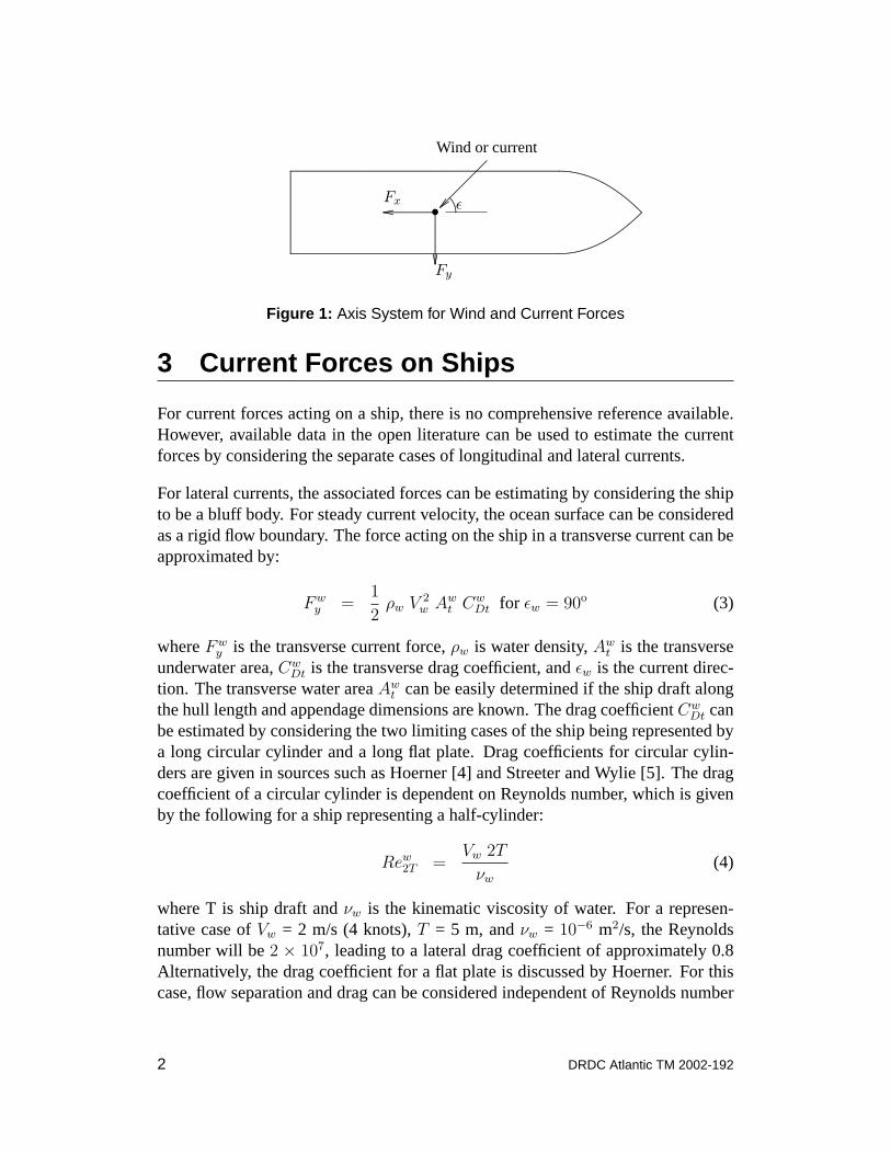
Dt are longitudinal and transverse wind drag coefficients,εa iswind direction, andδa is a wind force deflection parameter based on ship abovewater geometry. Figure 1 shows the direction conventions for forces and winddirection.
DRDC Atlantic TM 2002-192 1
.............................................................................................................................................................................................................................................................................................................................................................................................................................................................................................................................................................................................................................................................................................................................................................................................................................................................................................................................................................................................................................................................................................................
....................................................................................................................................................................
.....................................................................
................................
...............................................................•.............................................................................................................................
Fx.............................................................................................................................
Fy
......................................................................................................................................................
........
....................ε
Wind or current
Figure 1: Axis System for Wind and Current Forces
3 Current Forces on Ships
For current forces acting on a ship, there is no comprehensive reference available.However, available data in the open literature can be used to estimate the currentforces by considering the separate cases of longitudinal and lateral currents.
For lateral currents, the associated forces can be estimating by considering the shipto be a bluff body. For steady current velocity, the ocean surface can be consideredas a rigid flow boundary. The force acting on the ship in a transverse current can beapproximated by:
Fwy =
1
2ρw V 2
w Awt Cw
Dt for εw = 90o (3)
whereFwy is the transverse current force,ρw is water density,Aw
t is the transverseunderwater area,Cw
Dt is the transverse drag coefficient, andεw is the current direc-tion. The transverse water areaAw
t can be easily determined if the ship draft alongthe hull length and appendage dimensions are known. The drag coefficientCw
Dt canbe estimated by considering the two limiting cases of the ship being represented bya long circular cylinder and a long flat plate. Drag coefficients for circular cylin-ders are given in sources such as Hoerner [4] and Streeter and Wylie [5]. The dragcoefficient of a circular cylinder is dependent on Reynolds number, which is givenby the following for a ship representing a half-cylinder:
Rew2T =
Vw 2T
νw
(4)
where T is ship draft andνw is the kinematic viscosity of water. For a represen-tative case ofVw = 2 m/s (4 knots),T = 5 m, andνw = 10−6 m2/s, the Reynoldsnumber will be2 × 107, leading to a lateral drag coefficient of approximately 0.8Alternatively, the drag coefficient for a flat plate is discussed by Hoerner. For thiscase, flow separation and drag can be considered independent of Reynolds number
2 DRDC Atlantic TM 2002-192
but dependent on aspect ratio given by:
aw =2T
L(5)
The above aspect ratio includes a factor of 2 in the numerator because the oceansurface is considered to be a rigid flow boundary with associated flow symmetry.For a representative case with ship draftT of 5 m and ship lengthL of 120 m, theassociated aspect ratioaw will be 0.08, leading to a transverse drag coefficient ofapproximately 1.3. In summary, the transverse drag coefficientCw
Dt for a ship likelyfalls between the limiting values of 0.8 and 1.3 for a circular cylinder and flat plate.
For longitudinal currents, the associated forces can be estimated using the exten-sive literature on ship resistance. As given in Newman [6], ship resistance can beexpressed as follows:
Fwx =
1
2ρw V 2
w Sw [CwF (Rew
L) + CwR(Fn)] for εw = 0o (6)
whereSw is hull wetted surface area,CwF is the frictional resistance coefficient,
RewL is Reynolds number based on hull length,Cw
R is the residual resistance coeffi-cient, andFn is the Froude number. The Reynolds number and Froude number areevaluated by:
RewL =
Vw L
νw
(7)
Fn =Vw√g L
(8)
whereL is ship length between perpendiculars andg is gravitational acceleration.For a representative case with current velocityVw of 2 m/s, and ship lengthL of120 m, the Reynolds numberRew
L will be 2.4×10⁸ and the Froude numberFn willbe 0.06. Based on data presented by van Manen and van Oossanen [2], the fric-tional resistance coefficient will be approximately 0.002 and the residual resistancecoefficient will be approximately 0.0005. For a naval ship in currents of 5 knotsand less, both frictional and residual resistance coefficients will have little varia-tion with current velocity (i.e., force will be proportional to the square of currentvelocity).
To model the variation of current forces with angle of attack, the form developed byBlendermann for wind forces appears to be suitable. Assuming residual resistanceto be negligible, the current forces acting on the ship for arbitrary angles of attackare:
Fwx =
1
2ρw V 2
w Sw CwDl
cos εw
1 − δw
2
(1− Cw
Dl Sw
CwDt Aw
t
)sin2 2εw
(9)
DRDC Atlantic TM 2002-192 3
Fwy =
1
2ρw V 2
w Awt Cw
Dt
sin εw
1 − δw
2
(1− Cw
Dl Sw
CwDt Aw
t
)sin2 2εw
(10)
The main difference between the current force equations above and the wind forceequations Equations (1) and (2) is that the longitudinal current force is referencedto the wetted surface areaSw due to the dominant role of skin friction. The longitu-dinal current force in Equation (9) is expressed in terms of a single drag coefficientgiven by:
CwDt = Cw
F (RewL) + Cw
R(Fn) (11)
4 Induced Drift Velocity
The drift velocity induced by current and winds forces is of interest to ship oper-ators. Drift velocity can be estimated by considering the ship to be drifting alongwith the current at velocityVw plus a relative drift velocityVr induced by the wind.The relative drift velocity can be evaluated by considering equilibrium between airand water drag forces. Assuming the relative drift velocity is small relative to windvelocity, the relative drift velocity for longitudinal winds is:
Vr = Va
√ρa Aa
l CaDl
ρw Sw CwDl
(12)
Similarly, the relative drift velocity for transverse winds is:
Vr = Va
√ρa Aa
t CaDt
ρw Awt Cw
Dt
(13)
The relative transverse velocity is of greater practical relevance than the relativelongitudinal velocity because the ship propeller can easily compensate for longitu-dinal drift velocity.
4 DRDC Atlantic TM 2002-192
5 Predictions of Wind and Current Forcesfor Canadian Forces Ships
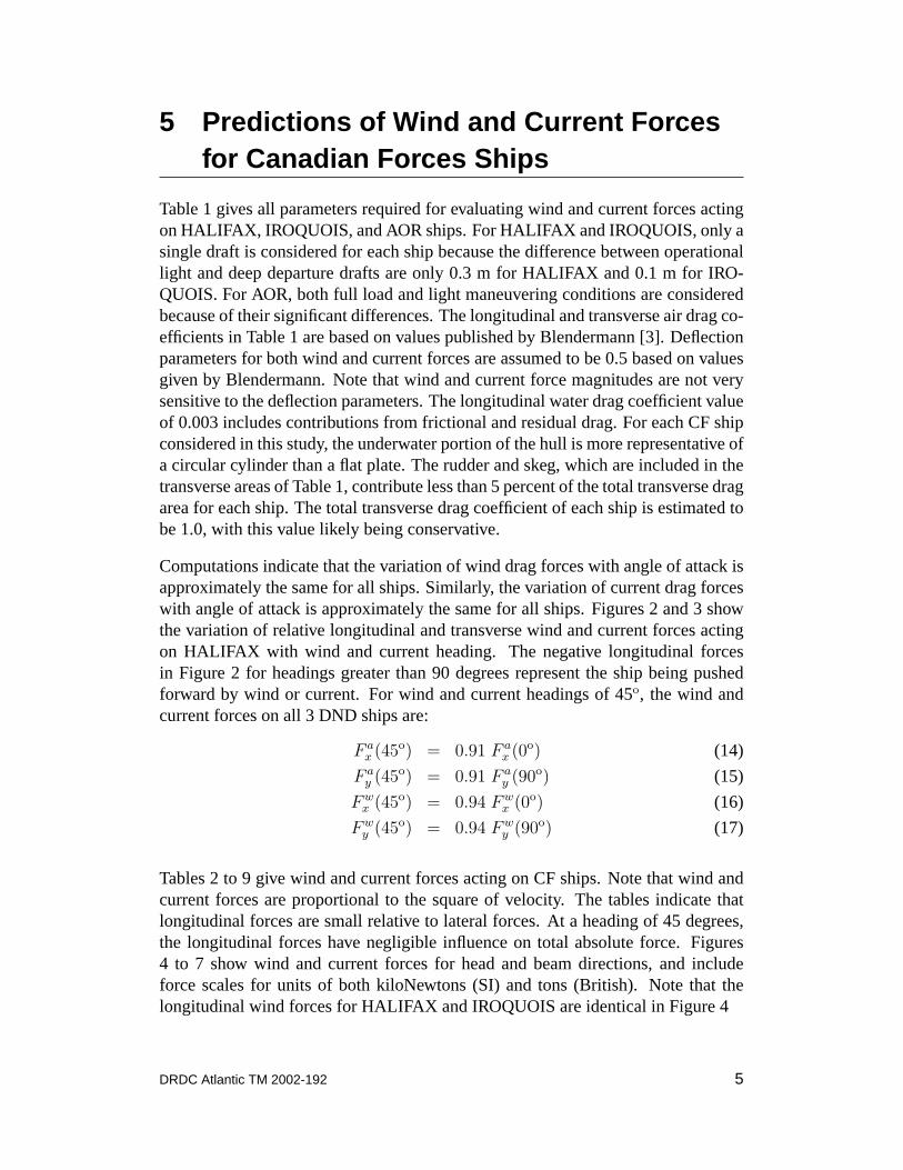
Table 1 gives all parameters required for evaluating wind and current forces actingon HALIFAX, IROQUOIS, and AOR ships. For HALIFAX and IROQUOIS, only asingle draft is considered for each ship because the difference between operationallight and deep departure drafts are only 0.3 m for HALIFAX and 0.1 m for IRO-QUOIS. For AOR, both full load and light maneuvering conditions are consideredbecause of their significant differences. The longitudinal and transverse air drag co-efficients in Table 1 are based on values published by Blendermann [3]. Deflectionparameters for both wind and current forces are assumed to be 0.5 based on valuesgiven by Blendermann. Note that wind and current force magnitudes are not verysensitive to the deflection parameters. The longitudinal water drag coefficient valueof 0.003 includes contributions from frictional and residual drag. For each CF shipconsidered in this study, the underwater portion of the hull is more representative ofa circular cylinder than a flat plate. The rudder and skeg, which are included in thetransverse areas of Table 1, contribute less than 5 percent of the total transverse dragarea for each ship. The total transverse drag coefficient of each ship is estimated tobe 1.0, with this value likely being conservative.
Computations indicate that the variation of wind drag forces with angle of attack isapproximately the same for all ships. Similarly, the variation of current drag forceswith angle of attack is approximately the same for all ships. Figures 2 and 3 showthe variation of relative longitudinal and transverse wind and current forces actingon HALIFAX with wind and current heading. The negative longitudinal forcesin Figure 2 for headings greater than 90 degrees represent the ship being pushedforward by wind or current. For wind and current headings of 45o, the wind andcurrent forces on all 3 DND ships are:
F ax (45o) = 0.91 F a
x (0o) (14)
F ay (45o) = 0.91 F a
y (90o) (15)
Fwx (45o) = 0.94 Fw
x (0o) (16)
Fwy (45o) = 0.94 Fw
y (90o) (17)
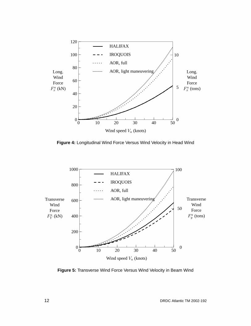
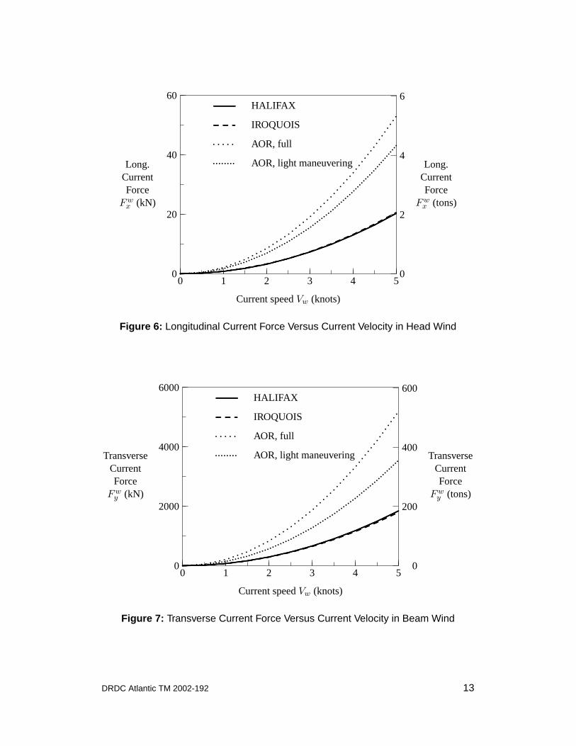
Tables 2 to 9 give wind and current forces acting on CF ships. Note that wind andcurrent forces are proportional to the square of velocity. The tables indicate thatlongitudinal forces are small relative to lateral forces. At a heading of 45 degrees,the longitudinal forces have negligible influence on total absolute force. Figures4 to 7 show wind and current forces for head and beam directions, and includeforce scales for units of both kiloNewtons (SI) and tons (British). Note that thelongitudinal wind forces for HALIFAX and IROQUOIS are identical in Figure 4
DRDC Atlantic TM 2002-192 5
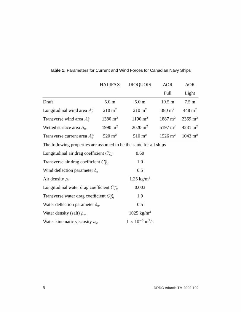
Table 1: Parameters for Current and Wind Forces for Canadian Navy Ships
HALIFAX IROQUOIS AOR AOR
Full Light
Draft 5.0 m 5.0 m 10.5 m 7.5 m
Longitudinal wind areaAal 210 m2 210 m2 380 m2 448 m2
Transverse wind areaAat 1380 m2 1190 m2 1887 m2 2369 m2
Wetted surface areaSw 1990 m2 2020 m2 5197 m2 4231 m2
Transverse current areaAwt 520 m2 510 m2 1526 m2 1043 m2
The following properties are assumed to be the same for all ships
Longitudinal air drag coefficientCaDl 0.60
Transverse air drag coefficientCaDt 1.0
Wind deflection parameterδa 0.5
Air densityρa 1.25 kg/m3
Longitudinal water drag coefficientCwDl 0.003
Transverse water drag coefficientCwDt 1.0
Water deflection parameterδw 0.5
Water density (salt)ρw 1025 kg/m3
Water kinematic viscosityνw 1× 10⁻⁶ m2/s
6 DRDC Atlantic TM 2002-192

0 45 90 135 180
Wind and current angles of attackεa andεw (degrees)
Head Bow quarter Beam Stern quarter Astern
−1
0
1
RelativeLongitudinal
Force
F ax (εa)/F a
x (0)
Fwx (εw)/Fw
x (0)
.........................................................Wind force
............. ............. ....... Current force
......................................................................................................................................................................................................................................................................................................................................................................................................................................................................................................................................................................................................................................................................................................................................................................................................................................................................................................................
............. ............. ............. ............. ............. ............. ............. ................................................................................................................................................................................................................................................................................. ............. ............. ............. ............. ............. ............. ............. .
Figure 2: Relative Longitudinal Wind and Current Forces Versus Heading forHALIFAX
0 45 90 135 180
Wind and current angles of attackεa andεw (degrees)
Head Bow quarter Beam Stern quarter Astern
0.0
0.2
0.4
0.6
0.8
1.0
1.2
RelativeTransverse
Force
F ay (εa)/F a
y (90o)
Fwy (εw)/Fw
y (90o)
.........................................................Wind force
............. ............. ....... Current force
.....................................................................................................................................................................................................................................................................................................................................................................................................................................................................................
............................................................................................................................................................................................................................................................................................................................................................................................................................................................................................................................................................................................................................................................................................................................................................................................
.............................................................................................................................................................................................................................
............. ............. ............. ............. ............. ............. ............. ............. ............. ............. ............. ............. ............. ..........................................................................................................................................................................................................................................
Figure 3: Relative Transverse Wind and Current Forces Versus Heading forHALIFAX
DRDC Atlantic TM 2002-192 7
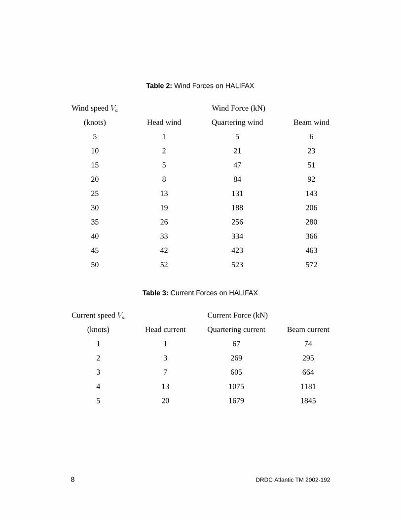
Table 2: Wind Forces on HALIFAX
Wind speedVa Wind Force (kN)
(knots) Head wind Quartering wind Beam wind
5 1 5 6
10 2 21 23
15 5 47 51
20 8 84 92
25 13 131 143
30 19 188 206
35 26 256 280
40 33 334 366
45 42 423 463
50 52 523 572
Table 3: Current Forces on HALIFAX
Current speedVa Current Force (kN)
(knots) Head current Quartering current Beam current
1 1 67 74
2 3 269 295
3 7 605 664
4 13 1075 1181
5 20 1679 1845
8 DRDC Atlantic TM 2002-192
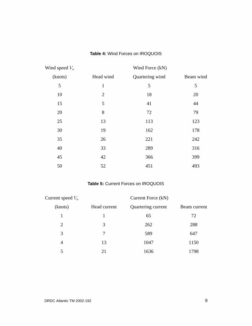
Table 4: Wind Forces on IROQUOIS
Wind speedVa Wind Force (kN)
(knots) Head wind Quartering wind Beam wind
5 1 5 5
10 2 18 20
15 5 41 44
20 8 72 79
25 13 113 123
30 19 162 178
35 26 221 242
40 33 289 316
45 42 366 399
50 52 451 493
Table 5: Current Forces on IROQUOIS
Current speedVa Current Force (kN)
(knots) Head current Quartering current Beam current
1 1 65 72
2 3 262 288
3 7 589 647
4 13 1047 1150
5 21 1636 1798
DRDC Atlantic TM 2002-192 9
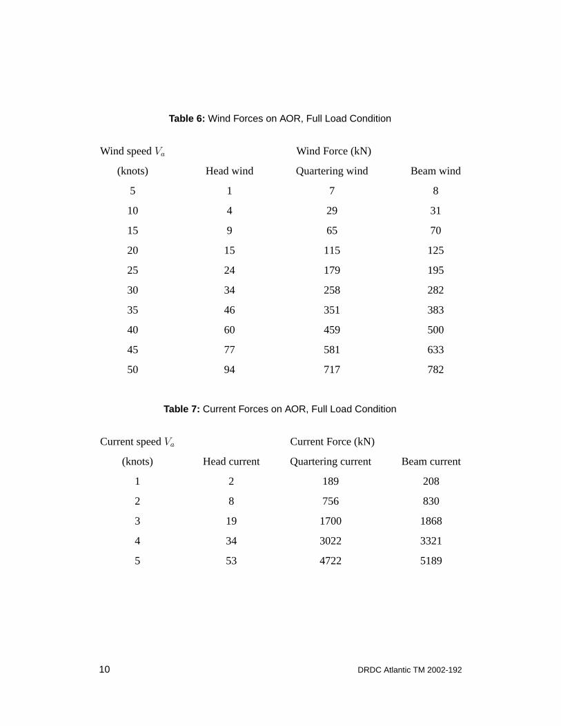
Table 6: Wind Forces on AOR, Full Load Condition
Wind speedVa Wind Force (kN)
(knots) Head wind Quartering wind Beam wind
5 1 7 8
10 4 29 31
15 9 65 70
20 15 115 125
25 24 179 195
30 34 258 282
35 46 351 383
40 60 459 500
45 77 581 633
50 94 717 782
Table 7: Current Forces on AOR, Full Load Condition
Current speedVa Current Force (kN)
(knots) Head current Quartering current Beam current
1 2 189 208
2 8 756 830
3 19 1700 1868
4 34 3022 3321
5 53 4722 5189
10 DRDC Atlantic TM 2002-192
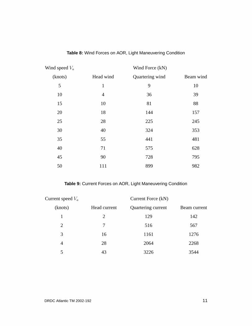
Table 8: Wind Forces on AOR, Light Maneuvering Condition
Wind speedVa Wind Force (kN)
(knots) Head wind Quartering wind Beam wind
5 1 9 10
10 4 36 39
15 10 81 88
20 18 144 157
25 28 225 245
30 40 324 353
35 55 441 481
40 71 575 628
45 90 728 795
50 111 899 982
Table 9: Current Forces on AOR, Light Maneuvering Condition
Current speedVa Current Force (kN)
(knots) Head current Quartering current Beam current
1 2 129 142
2 7 516 567
3 16 1161 1276
4 28 2064 2268
5 43 3226 3544
DRDC Atlantic TM 2002-192 11
0 10 20 30 40 50
Wind speedVa (knots)
0
20
40
60
80
100
120
Long.WindForce
F ax (kN)
0
5
10
Long.WindForce
F ax (tons)
.........................................................HALIFAX
............. ............. ....... IROQUOIS
. . . . . AOR, full
........ AOR, light maneuvering
.................................................................................................................................................................................................................................
..................................................................................................
..............................................................................
.....................................................................
..............................................................
.........................................................
.....................................
............. ............. ............. ............. ............. ............. ............. ............. ............. ............. ............. ............. ............. ............. ............. ............. ............. ............. ............. ............. ............. ...........
.. .......................... ...
..........
. . . . . . . . . .. . . . .
. . . .. ..
......
......
.....
....
....
..........
.......................
..........
........
........
........
........
....................................
Figure 4: Longitudinal Wind Force Versus Wind Velocity in Head Wind
0 10 20 30 40 50
Wind speedVa (knots)
0
200
400
600
800
1000
TransverseWindForce
F aY (kN)
0
50
100
TransverseWindForce
F ay (tons)
.........................................................HALIFAX
............. ............. ....... IROQUOIS
. . . . . AOR, full
........ AOR, light maneuvering
.....................................................................................................................................................................................................
.......................................................................................
......................................................................
.............................................................
........................................................
.....................................................
..................................................
................................................
...................................
............. ............. ............. ............. ............. ............. ............. ............. ............. ............. ............. ............. ............. ............. ............. ............. ............. ............. ............. ..........
... .......................... ..
........... ............. ...
.......... .........
. . . . . . . . . .. . . . .
. . . .. ..
......
......
.....
....
....
..........
......................
..........
........
........
........
........
.......................................
Figure 5: Transverse Wind Force Versus Wind Velocity in Beam Wind
12 DRDC Atlantic TM 2002-192
0 1 2 3 4 5
Current speedVw (knots)
0
20
40
60
Long.CurrentForce
Fwx (kN)
0
2
4
6
Long.CurrentForce
Fwx (tons)
.........................................................HALIFAX
............. ............. ....... IROQUOIS
. . . . . AOR, full
........ AOR, light maneuvering
...............................................................................................................................................................................................................................................................
...............................................................................................................
.......................................................................................
...........................................................................
....................................................................
..............
............. ............. ............. ............. ............. ............. ............. ............. ............. ............. ............. ............. ............. ............. ............. ............. ............. ............. ............. ............. ............. ............. ............. ............. .....
. . . . . . . . . .. . . .
. . . .. ..
......
......
....
....
...................
.........................
...........
..........
.........
........
........
........
..............
Figure 6: Longitudinal Current Force Versus Current Velocity in Head Wind
0 1 2 3 4 5
Current speedVw (knots)
0
2000
4000
6000
TransverseCurrentForce
Fwy (kN)
0
200
400
600
TransverseCurrentForce
Fwy (tons)
.........................................................HALIFAX
............. ............. ....... IROQUOIS
. . . . . AOR, full
........ AOR, light maneuvering
..........................................................................................................................................................................................................................................................................
...................................................................................................................
...........................................................................................
..............................................................................
....................................................
............. ............. ............. ............. ............. ............. ............. ............. ............. ............. ............. ............. ............. ............. ............. ............. ............. ............. ............. ............. ............. ............. ............. .............
. . . . . . . . . .. . . .
. . . .. ..
......
......
....
....
..................
............................
.............
..........
.........
........
........
........
....
Figure 7: Transverse Current Force Versus Current Velocity in Beam Wind
DRDC Atlantic TM 2002-192 13
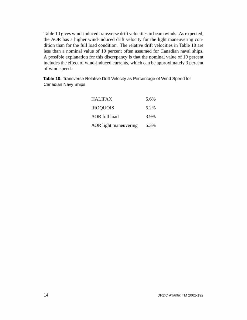
Table 10 gives wind-induced transverse drift velocities in beam winds. As expected,the AOR has a higher wind-induced drift velocity for the light maneuvering con-dition than for the full load condition. The relative drift velocities in Table 10 areless than a nominal value of 10 percent often assumed for Canadian naval ships.A possible explanation for this discrepancy is that the nominal value of 10 percentincludes the effect of wind-induced currents, which can be approximately 3 percentof wind speed.
Table 10: Transverse Relative Drift Velocity as Percentage of Wind Speed forCanadian Navy Ships
HALIFAX 5.6%
IROQUOIS 5.2%
AOR full load 3.9%
AOR light maneuvering 5.3%
14 DRDC Atlantic TM 2002-192
6 Uncertainties in Predicted Forces
When applying the present force predictions, it is important to be aware of theassociated level of uncertainties in predictions. In the present work, there are un-certainties regarding the drag coefficients selected for given ship geometries. Datafrom Blendermann [3] suggest that longitudinal drag coefficients will have a stan-dard error of approximately 20 percent, while transverse drag coefficients will havea standard error of approximately 10 percent. To account for these uncertainties,the drag coefficients chosen for the present computations (see Table 1) are slightlyconservative.
In an operational context, the largest uncertainties will likely be associated withestimates of wind and current velocities. Wind and current forces are both pro-portional to velocity squared; thus, a relative error in wind or current velocity willlead to a relative error in drag force which is approximately twice as large. Conse-quently, it is likely that errors due to wind or current velocities will lead to errorslarger than those due to drag coefficients.
Wind and current forces will also vary with ship loading condition. This effect willlikely be minor for HALIFAX and IROQUOIS, which maintain relatively constantdrafts. For AOR, large changes in drafts will significantly affect wind and currentprofile, but will have little effect on wetted surface area. Changes to profile areascan be evaluated by:
Aal (T + ∆T ) = Aa
l (T ) − B ∆T (18)
Aat (T + ∆T ) = Aa
t (T ) − L ∆T (19)
Awt (T + ∆T ) = Aw
t (T ) + L ∆T (20)
where∆T is change in draft andB is ship beam.
7 Conclusions
Predictions have been developed for wind and current forces acting on CanadianForces ships during tug operations. Transverse forces in transverse flows are muchlarger than longitudinal forces in longitudinal flows. For wind and currents ap-proaching from 45 degrees off the bow, transverse forces are much larger than lon-gitudinal forces.
Tables have been developed for wind and current forces on HALIFAX, IROQUOISand AOR ships. In an operational context, the greatest errors in force predictionswill likely be due to errors in wind or current velocities.
DRDC Atlantic TM 2002-192 15
References
1. K. McTaggart and M. Savage, “Wind Heeling Loads on a Naval Frigate,” inSTAB ’94, Fifth International Conference on Stability of Ships and OceanVehicles(Melbourne, Florida, 1994).
2. J.D. van Manen and P. van Oossanen,Principles of Naval Architecture, VolumeII (Society of Naval Architects and Marine Engineers, 1988), Ch. 5,Resistance.
3. W. Blendermann, “Parameter Identification of Wind Loads on Ships,”Journalof Wind Engineering and Industrial Aerodynamics51, 339–351 (1994).
4. S.F. Hoerner,Fluid-Dynamic Drag, published by the author, Midland Park,New Jersey, 1958.
5. V.L. Streeter and E.B. Wylie,Fluid Mechanics, McGraw-Hill, New York,1979.
6. J.N. Newman,Marine Hydrodynamics, MIT Press, Cambridge, Massachusetts,1977.
16 DRDC Atlantic TM 2002-192

Symbols
Aal , Aa
t longitudinal and transverse wind profile areasaw aspect ratio of underwater portion of shipB ship beamCa
Dl, CaDt longitudinal and transverse air drag coefficients
CwDl, Cw
Dt longitudinal and transverse water drag coefficientsCw
F longitudinal water friction drag coefficientCw
R longitudinal water residual drag coefficientF a
x , F ay longitudinal and transverse wind forces
Fwx , Fw
y longitudinal and transverse wind forcesFn Froude numberg gravitational accelerationRew
L ship Reynolds number in water based on ship lengthRew
2T ship Reynolds number in water based on twice ship draftSw wetted surface areaT ship draftVa air velocityVr wind-induced ship velocity relative to currentsVw water velocity∆T change in ship draftδa wind force deflection parameterδw current force deflection parameterεa wind relative directionεw current relative directionνw kinematic viscosity of waterρa air densityρw water density
DRDC Atlantic TM 2002-192 17

This page intentionally left blank.
18 DRDC Atlantic TM 2002-192
DOCUMENT CONTROL DATA
(Security classification of title, body of abstract and indexing annotation must be entered when document is classified)
1. ORIGINATOR (the name and address of the organizationpreparing the document).
Defence R&D Canada - Atlantic
2. SECURITY CLASSIFICATION (overallsecurity classification of the document includingspecial warning terms if applicable)
UNCLASSIFIED
3. TITLE (The complete document title as indicated on the title page. Its classification should be indicated by theappropriate abbreviation (S,C,R or U) in parentheses after the title.)
Wind and Current Forces Acting on Canadian Forces Ships During TugOperations
4. AUTHORS (Last name, first name, middle initial. If military, show rank, e.g. Doe, Maj. John E.)
McTaggart, Kevin A.
5. DATE OF PUBLICATION (month and year of publication ofdocument)
November 2002
6a. NO. OF PAGES(total includingAnnexes, Appendices,etc).
30
6b. NO. OF REFS (totalcited in document)
6
7. DESCRIPTIVE NOTES (The category of the document, e.g. technical report, technical note or memorandum. Ifappropriate, enter the type of report, e.g. interim, progress, summary, annual or final.)
Technical Memorandum
8. SPONSORING ACTIVITY (the name of the department project office or laboratory sponsoring the research anddevelopment. Include address).
Defence R&D Canada - Atlantic, PO Box 1012, Dartmouth, NS, Canada B2Y 3Z7
9a. PROJECT OR GRANT NO. (If appropriate, the applicableresearch and development project or grant number under whichthe document was written.)
11GK02
9b. CONTRACT NO. (if appropriate, theapplicable number under which the documentwas written).
10a. ORIGINATOR’S DOCUMENT NUMBER (the officialdocument number by which the document is identified by theoriginating activity. This number must be unique.)
DRDC Atlantic TM 2002-192
10b. OTHER DOCUMENT NOs. (Any othernumbers which may be assigned this documenteither by the originator or by the sponsor.)
11. DOCUMENT AVAILABILITY (any limitations on further dissemination of the document, other than thoseimposed by security classification)
(X) Unlimited distribution( ) Defence departments and defence contractors; further distribution only as approved( ) Defence departments and Canadian defence contractors; further distribution only as approved( ) Government departments and agencies; further distribution only as approved( ) Defence departments; further distribution only as approved( ) Other (please specify):
12. DOCUMENT ANNOUNCEMENT (any limitation to the bibliographic announcement of this document. This willnormally correspond to the Document Availability (11). However, where further distribution (beyond the audiencespecified in (11) is possible, a wider announcement audience may be selected).
DRDC Atlantic TM 2002-192 19
13. ABSTRACT (a brief and factual summary of the document. It may also appear elsewhere in the body of the documentitself. It is highly desirable that the abstract of classified documents be unclassified. Each paragraph of the abstract shallbegin with an indication of the security classification of the information in the paragraph (unless the document itself isunclassified) represented as (S), (C), (R), or (U). It is not necessary to include here abstracts in both official languagesunless the text is bilingual).
This report presents predictions of wind and current forces on Canadian Forcesships during towing operations. Longitudinal and transverse forces are treated asfunctions of incident flow direction. For the ship geometries considered, trans-verse forces arising from transverse flows are much greater than longitudinalforces from longitudinal flow. For winds or currents from the bow quarter (45degrees), transverse forces are much greater than longitudinal forces. The reportincludes tables of wind and current forces acting on HALIFAX, IROQUOIS andAOR ships. In an operational context, the greatest errors in force predictions willlikely be due to errors in wind or current velocities.
14. KEYWORDS, DESCRIPTORS or IDENTIFIERS (technically meaningful terms or short phrases that characterizea document and could be helpful in cataloguing the document. They should be selected so that no security classificationis required. Identifiers, such as equipment model designation, trade name, military project code name, geographiclocation may also be included. If possible keywords should be selected from a published thesaurus. e.g. Thesaurus ofEngineering and Scientific Terms (TEST) and that thesaurus-identified. If it not possible to select indexing terms whichare Unclassified, the classification of each should be indicated as with the title).
currentdrag forcesshipstowingwind
20 DRDC Atlantic TM 2002-192