Embed Size (px)
Citation preview
Wind Design Standard for Edge SystemsUsed with Low Slope Roofing Systems
1.0 INTRODUCTION (See Commentary: 1)
The following standard is a reference forthose who design, specify or install edgematerials used with low slope roofing sys-tems. This Standard focuses primarily ondesign for wind resistance. Nevertheless, itdoes address corrosion as well as fasciathicknesses that lead to satisfactory flat-ness. It is intended for use with the specifi-cations and requirements of the manufactur-ers of the specific roofing materials and theedge systems used in the roofing assembly,excluding gutters. The membrane manufac-turer shall be consulted for specific recom-mendations for making the roof watertight atthe edge.
This design standard addresses copingsand horizontal roof edges, and the followingfactors shall be considered in designing aroof edge.
• Structural integrity of the substrate that anchors the edge (e.g. nailers)
• Wind resistance of the edge detail• Materials specifications
This guide has been revised in accordancewith the ASCE 7-021 document titled“Minimum Design Loads for Buildings andOther Structures” to provide a relatively sim-ple calculation method for the determinationof the wind uplift pressures on componentsand cladding for any building. The completeASCE 7-02 document has not been dupli-cated here, however key information fromthat document appears here so that mostconditions will not require direct reference tothat document.
2.0 GENERAL DESIGN CONSIDERATIONSAND DEFINITIONS (See Commentary: 2)
All materials for roof edge construction shallhave sufficient strength to withstand thedesign wind load. The following factors applywhen designing a roof edge system: Windspeed, building height, Exposure Factor,topography, Importance Factor, corner andperimeter regions, edge condition, galvaniccompatibility and flatness of fascias.
2.1. ROOF SLOPE Roof Slope is accounted for in the pressurecoefficient factors used in this document. Onlyroof slopes ≤10° are addressed by this docu-ment.
2.2. WIND SPEED (See Commentary: 2.2)Basic wind speed values used in the designcalculations are 3-second maximum peakgust speeds in miles per hour (0.45 m/s)measured at 33 ft (10 m) above ground forExposure Factor C associated with an annualprobability of 0.02 (50 year return). Thesevalues are taken from the ANSI/ASCE 7-021
document (See Attachment I) or the authorityhaving jurisdiction. (See Commentary: 2.2)The authority having jurisdiction shall be con-tacted for verification of wind data. The basicwind speed, V used in the determination ofthe design wind loads on buildings shall beas given in Attachment I except as follows:
Special Wind Regions: The basic windspeed shall be increased where records orexperience indicate that the wind speedsare higher than those reflected inAttachment I. Mountainous terrain, gorgesand special regions shown in Attachment
DISCLAIMERThis standard is for use by architects, engineers, roofing contractors and owners of low slope roofing systems.
SPRI, ITS MEMBERS AND EMPLOYEES DO NOT WARRANT THAT THIS STANDARD IS PROPER AND APPLICABLE UNDER ALL CONDITIONS.
Copyright by SPRI 2003. 77 Rumford Avenue, Waltham, MA 02453. www.spri.org. All Rights Reserved.
[ 1 ]
ANS/SPRI ES-1 2003 APPROVED DECEMBER 11, 2003
ES-1'04 4/10/04 1:26 AM Page 2
I shall be examined for unusual wind condi-tions. The authority having jurisdiction, ifnecessary, shall adjust the values given inAttachment I to account for higher localwind speeds. Such adjustments shall bebased on meteorological information and anestimate of the basic wind speed obtainedin accordance with the provisions of C.2 asfollows.
Estimation of Basic Wind Speeds fromRegional Climatic Data:Regional climatic data shall only be used inlieu of the basic wind speeds given inAttachment I when: (a) Approved extreme-value statistical-analysis procedures havebeen employed in reducing the data; (b)and the length of record, sampling error,averaging time, anemometer height, dataquality and terrain exposure have beentaken into account. Section 6.5.7 of ASCE7-021 shall be used to adjust design windspeed for the intensifying effects of valleysand other unique topographic features suchas hills or escarpments.
Limitation: Wind conditions above basicwind speeds (e.g. tornadoes) have not beenconsidered in developing the basic windspeed distributions.
2.3. BUILDING HEIGHTThe building height shall be measured fromthe ground to the eave of the roof section.Specific topographic features, such as hills,shall be considered when calculating build-ing height.
2.4. ROOF EDGE REGIONSWind forces near building corner regionsare of greater intensity than in the perimeterregions between corners. These regions aredefined as follows:
2.4.1. CORNER REGIONFor buildings with mean roof height of 60feet (18 m) or less: The corner region is adistance from the building corner that is10% of the minimum building width or 40%of the building height at the eaves, whichev-er is smaller, but not less than 4% of theminimum building width and not less than 3feet (0.9 m).
For buildings with mean roof height greater
than 60 feet (18 m): The corner region is adistance from the building corner that is10% of the minimum building width but notless than 3 feet (0.9 m).
2.4.2. PERIMETER The perimeter is the section of roof edgebetween building corner regions as definedin Section 2.4.1 (above). The edge condi-tion includes the roof edge device (edgeflashing or coping) and the nailer or othersubstrate to which the edge device isattached.
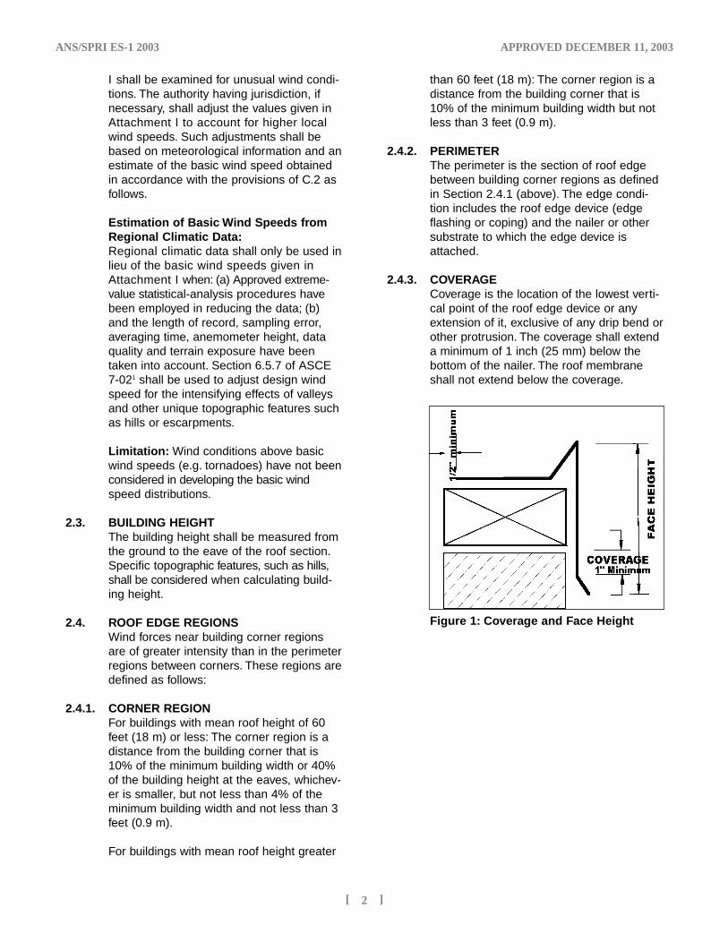
2.4.3. COVERAGE Coverage is the location of the lowest verti-cal point of the roof edge device or anyextension of it, exclusive of any drip bend orother protrusion. The coverage shall extenda minimum of 1 inch (25 mm) below thebottom of the nailer. The roof membraneshall not extend below the coverage.
ANS/SPRI ES-1 2003 APPROVED DECEMBER 11, 2003
[ 2 ]
Figure 1: Coverage and Face Height
ES-1'04 4/10/04 1:26 AM Page 3
ANS/SPRI ES-1 2003 APPROVED DECEMBER 11, 2003
[ 3 ]
Exposure Categories
B: Exposure B shall apply where the ground surface roughness condition, as defined by SurfaceRoughness B, prevails in the upwind direction for a distance of at least 2630 ft (800 m) or 10 times theheight of the building, whichever is greater.Exception: For buildings whose mean roof height is less than or equal to 30 ft (9.1 m), the upwind dis-tance may be reduced to 1500 ft (457 m)
C: Exposure C shall apply for all cases where exposures B or D do not apply.
D: Exposure D shall apply where the ground surface roughness, as defined by surface roughness D, pre-vails in the upwind direction for a distance at least 5000 ft (1524 m) or 10 times the building height,whichever is greater. Exposure D shall extend inland from the shoreline for a distance of 660 ft (200 m)or 10 times the height of the building, whichever is greater. For a site located in the transition zonebetween exposure categories, the category resulting in the largest wind forces shall be used. Exception:An intermediate exposure between the above categories is permitted in a transition zone provided that itis determined by a rational analysis method defined in the recognized literature.
3.0 EXPOSURE (See Commentary: 2.5)The building shall be classified into one ofthe following Exposures based on surround-ing terrain:.
4.0 IMPORTANCE FACTOR (See Commentary: 2.6) Buildings fitting one of the following criteriashall have an “Importance Factor” included
in the wind design calculations. Table 1explains these building classifications. Referto Section 7.1 for use of Importance Factor.
Nature of Occupancy Category Importance Factor
Non-Hurricane HurricaneProne Regions Prone& Alaska. RegionsV=85-100 mph. V>100 mph.
Buildings and other structures that represent a low hazard to human I 0.87 0.77life in the event of failure including, but not limited to:
• Agricultural facilities• Certain temporary facilities• Minor storage facilities
All buildings and other structures except those listed in II 1.00 1.00Categories I, III, and IV
• Buildings and other structures that represent a substantial hazard III 1.15 1.15to human life in the event of failure including, but not limited to:
• Buildings and other structures where more than 300 people congregate in one area
• Buildings and other structures with day care facilities with capacity greater than 150
• Buildings and other structures with elementary school or secondary school facilities with capacity greater than 250
• Buildings and other structures with a capacity greater than 500 for colleges or adult education facilities
• Health care facilities with a capacity of 50 or more resident patients but not having surgery or emergency treatment facilities
Table 1
ES-1'04 4/10/04 1:26 AM Page 6
ANS/SPRI ES-1 2003 APPROVED DECEMBER 11, 2003
[ 4 ]
• Jails and detention facilities• Power generating stations and other public utility facilities not
included in Category IV• Buildings and other structures not included in Category IV
(including, but not limited to, facilities that manufacture, process, handle, store, use, or dispose of such substances as hazardous fuels, hazardous chemicals, hazardous waste, or explosives) containing sufficient quantities of hazardous materials to be dangerous to the public if released.
• Buildings and other structures containing hazardous materials shall be eligible for classification as Category II structures if it can be demonstrated to the satisfaction of the authority having jurisdiction by a hazard assessment as described in Section 1.5.2 that a release of the hazardous material does not pose a threat to the public.
• Buildings and other structures designated as essential facilities IV 1.15 1.15including, but not limited to:
• Hospitals and other health care facilities having surgery or emergency treatment facilities
• Fire, rescue, ambulance, and police stations and emergency vehicle garages
• Designated earthquake, hurricane, or other emergency shelters• Designated emergency preparedness, communication, and
operation centers and other facilities required for emergency response
• Power generating stations and other public utility facilities required in an emergency
• Ancillary structures (including, but not limited to, communication towers, fuel storage tanks, cooling towers, electrical substation structures, fire water storage tanks or other structures housing or supporting water, or other fire-suppression material or equipment) required for operation of Category IV structures during an emergency
• Aviation control towers, air traffic control centers, and emergency aircraft hangars
• Water storage facilities and pump structures required to maintain water pressure for fire suppression
• Buildings and other structures having critical national defense functions
• Buildings and other structures (including, but not limited to, facilities that manufacture, process, handle, store, use, or dispose of such substances as hazardous fuels, hazardous chemicals, hazardous waste, or explosives) containing extremely hazardous materials where the quantity of the material exceeds a threshold quantity established by the authority having jurisdiction.
• Buildings and other structures containing extremely hazardous materials shall be eligible for classification as Category II structures if it can be demonstrated to the satisfaction of the authority having jurisdiction by a hazard assessment as described in Section 1.5.2 that a release of the extremely hazardous material does not pose a threat to the public. This reduced classification shall not be permitted if the buildings or other structures also function as essential facilities.
From ASCE 7/021
Nature of Occupancy Category Importance Factor
Table 1 continued
ES-1'04 4/10/04 1:26 AM Page 7
ANS/SPRI ES-1 2003 APPROVED DECEMBER 11, 2003
[ 5 ]
5.0 SYSTEM REQUIREMENTS (See Commentary: 5)
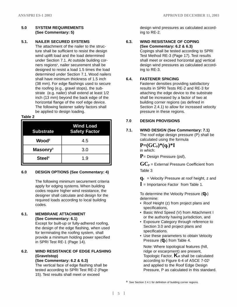
5.1. NAILER SECURED SYSTEMSThe attachment of the nailer to the struc-ture shall be sufficient to resist the designwind uplift load and the load determinedunder Section 7.1. At outside building cor-ners regionsa, nailer securement shall bedesigned to resist a load 1.5 times the loaddetermined under Section 7.1. Wood nailersshall have minimum thickness of 1.5 inch(38 mm). For edge flashings used to securethe roofing (e.g., gravel stops), the sub-strate (e.g. nailer) shall extend at least 1/2inch (13 mm) beyond the back edge of thehorizontal flange of the roof edge device.The following fastener safety factors shallbe applied to design loading.
6.0 DESIGN OPTIONS (See Commentary: 4)
The following minimum securement criteriaapply for edging systems. When buildingcodes require higher wind resistance, thedesigner shall calculate and design for therequired loads according to local buildingcodes.
6.1. MEMBRANE ATTACHMENT (See Commentary: 6.1)Except for built-up or fully-adhered roofing,the design of the edge flashing, when usedfor terminating the roofing system, shallprovide a minimum holding power specifiedin SPRI Test RE-1 (Page 14).
6.2. WIND RESISTANCE OF EDGE FLASHING(Gravelstop) (See Commentary: 6.2 & 6.3)The vertical face of edge flashing shall betested according to SPRI Test RE-2 (Page15). Test results shall meet or exceed
design wind pressures as calculated accord-ing to RE-2.
6.3. WIND RESISTANCE OF COPING (See Commentary: 6.2 & 6.3)Copings shall be tested according to SPRITest Method RE-3 (Page 17). Test resultsshall meet or exceed horizontal and verticaldesign wind pressures as calculated accord-ing to RE-3.
6.4. FASTENER SPACINGFastener densities providing satisfactoryresults in SPRI Tests RE-2 and RE-3 forattaching the edge device to the substrateshall be increased by a factor of two atbuilding corner regions (as defined inSection 2.4.1) to allow for increased velocitypressure in these regions.
7.0 DESIGN PROVISIONS
7.1. WIND DESIGN (See Commentary: 7.1)The roof edge design pressure (P) shall becalculated using the formula
P=(GCp)*(qz)*Iin which:
P= Design Pressure (psf),
GCp = External Pressure Coefficient from
Table 3
qz = Velocity Pressure at roof height, z and
I = Importance Factor from Table 1.
To determine the Velocity Pressure (qz)determine:• Roof Height (z) from project plans and
specifications, • Basic Wind Speed (V) from Attachment I
or the authority having jurisdiction, and • Exposure Category through reference to
Section 3.0 and project plans and specifications.
• Use these parameters to obtain Velocity Pressure (qz) from Table 4.
Note: Where topological features (hill, ridge or escarpment) are present, Topologic Factor, Kzt shall be calculated according to Figure 6-4 of ASCE 7-021
and applied to the Roof Edge Design Pressure, P as calculated in this standard.
Table 2
Wind LoadSubstrate Safety Factor
Wood2 4.5
Masonry3 3.0
Steel4 1.9
a See Section 2.4.1 for definition of building corner regions.
ES-1'04 4/10/04 1:26 AM Page 10
ANS/SPRI ES-1 2003 APPROVED DECEMBER 11, 2003
[ 6 ]
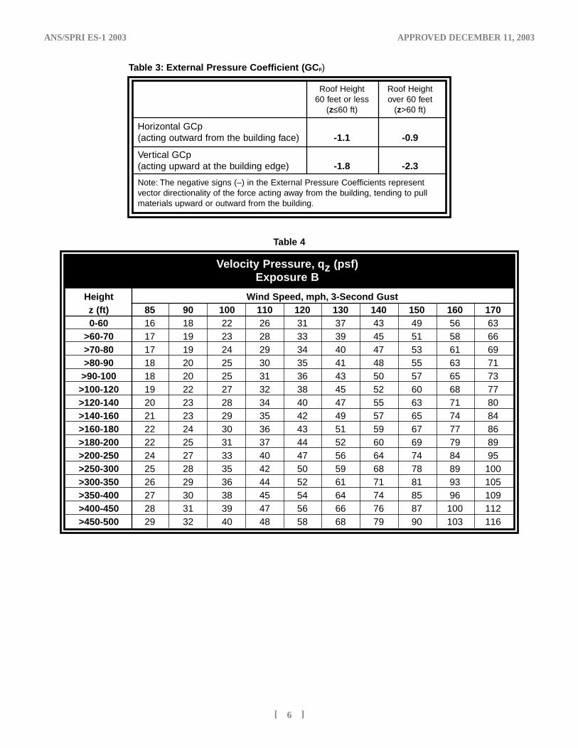
Roof Height Roof Height60 feet or less over 60 feet
(z≤60 ft) (z>60 ft)
Horizontal GCp(acting outward from the building face) -1.1 -0.9
Vertical GCp(acting upward at the building edge) -1.8 -2.3
Note: The negative signs (–) in the External Pressure Coefficients representvector directionality of the force acting away from the building, tending to pullmaterials upward or outward from the building.
Table 3: External Pressure Coefficient (GCp)
Table 4
Velocity Pressure, qz (psf)Exposure B
Height Wind Speed, mph, 3-Second Gustz (ft) 85 90 100 110 120 130 140 150 160 1700-60 16 18 22 26 31 37 43 49 56 63
>60-70 17 19 23 28 33 39 45 51 58 66>70-80 17 19 24 29 34 40 47 53 61 69>80-90 18 20 25 30 35 41 48 55 63 71>90-100 18 20 25 31 36 43 50 57 65 73>100-120 19 22 27 32 38 45 52 60 68 77>120-140 20 23 28 34 40 47 55 63 71 80>140-160 21 23 29 35 42 49 57 65 74 84>160-180 22 24 30 36 43 51 59 67 77 86>180-200 22 25 31 37 44 52 60 69 79 89>200-250 24 27 33 40 47 56 64 74 84 95>250-300 25 28 35 42 50 59 68 78 89 100>300-350 26 29 36 44 52 61 71 81 93 105>350-400 27 30 38 45 54 64 74 85 96 109>400-450 28 31 39 47 56 66 76 87 100 112>450-500 29 32 40 48 58 68 79 90 103 116
ES-1'04 4/10/04 1:26 AM Page 11
ANS/SPRI ES-1 2003 APPROVED DECEMBER 11, 2003
[ 7 ]
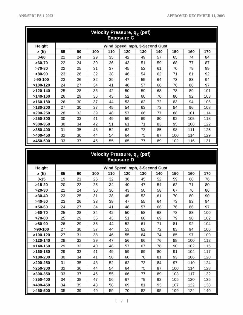
Velocity Pressure, qz (psf)Exposure C
Height Wind Speed, mph, 3-Second Gustz (ft) 85 90 100 110 120 130 140 150 160 1700-60 21 24 29 35 42 49 57 65 74 84
>60-70 22 24 30 36 43 51 59 68 77 87>70-80 22 25 31 37 45 52 61 70 79 89>80-90 23 26 32 38 46 54 62 71 81 92>90-100 23 26 32 39 47 55 64 73 83 94>100-120 24 27 34 41 48 57 66 76 86 97>120-140 25 28 35 42 50 59 68 78 89 101>140-160 26 29 36 43 52 60 70 80 92 103>160-180 26 30 37 44 53 62 72 83 94 106>180-200 27 30 37 45 54 63 73 84 96 108>200-250 28 32 39 48 57 66 77 88 101 114>250-300 30 33 41 49 59 69 80 92 105 118>300-350 30 34 42 51 61 71 83 95 108 122>350-400 31 35 43 52 62 73 85 98 111 125>400-450 32 36 44 54 64 75 87 100 114 129>450-500 33 37 45 55 65 77 89 102 116 131
Velocity Pressure, qz (psf)Exposure D
Height Wind Speed, mph, 3-Second Gustz (ft) 85 90 100 110 120 130 140 150 160 1700-15 19 21 26 32 38 45 52 59 68 76
>15-20 20 22 28 34 40 47 54 62 71 80>20-30 21 24 30 36 43 50 58 67 76 86>30-40 23 25 31 38 45 53 61 70 80 90>40-50 23 26 33 39 47 55 64 73 83 94>50-60 24 27 34 41 48 57 66 76 86 97>60-70 25 28 34 42 50 58 68 78 88 100>70-80 25 29 35 43 51 60 69 79 90 102>80-90 26 29 36 44 52 61 71 81 92 104>90-100 27 30 37 44 53 62 72 83 94 106>100-120 27 31 38 46 55 64 74 85 97 109>120-140 28 32 39 47 56 66 76 88 100 112>140-160 29 32 40 48 57 67 78 90 102 115>160-180 29 33 41 49 59 69 80 91 104 117>180-200 30 34 41 50 60 70 81 93 106 120>200-250 31 35 43 52 62 73 84 97 110 124>250-300 32 36 44 54 64 75 87 100 114 128>300-350 33 37 46 55 66 77 89 103 117 132>350-400 34 38 47 56 67 79 92 105 120 135>400-450 34 39 48 58 69 81 93 107 122 138>450-500 35 39 49 59 70 82 95 109 124 140
ES-1'04 4/10/04 1:26 AM Page 14
ANS/SPRI ES-1 2003 APPROVED DECEMBER 11, 2003
[ 8 ]
Roof edge designs shall pass tests RE-1, RE-2 andRE-3 as appropriate for the application:
• Edge devices designed to act as membrane terminations shall pass SPRI Test RE-1.
• Edge flashings and other edge devices for which the exposed horizontal component is 4 inches (100 mm) or less the exposed horizontal component area (edge flashings, etc.) shall pass SPRI Test RE-2.
• Copings and other devices for which the exposed horizontal flange exceeds 4 inches (100 mm) shall pass SPRI Test RE-3. To allow for higher wind loads at corners, double the fastening in the corner region instead of testing corner assemblies when the tested assembly passes RE-3.
Exposed areas in the above requirements shall bethose elements upon which the wind forces actdirectly.
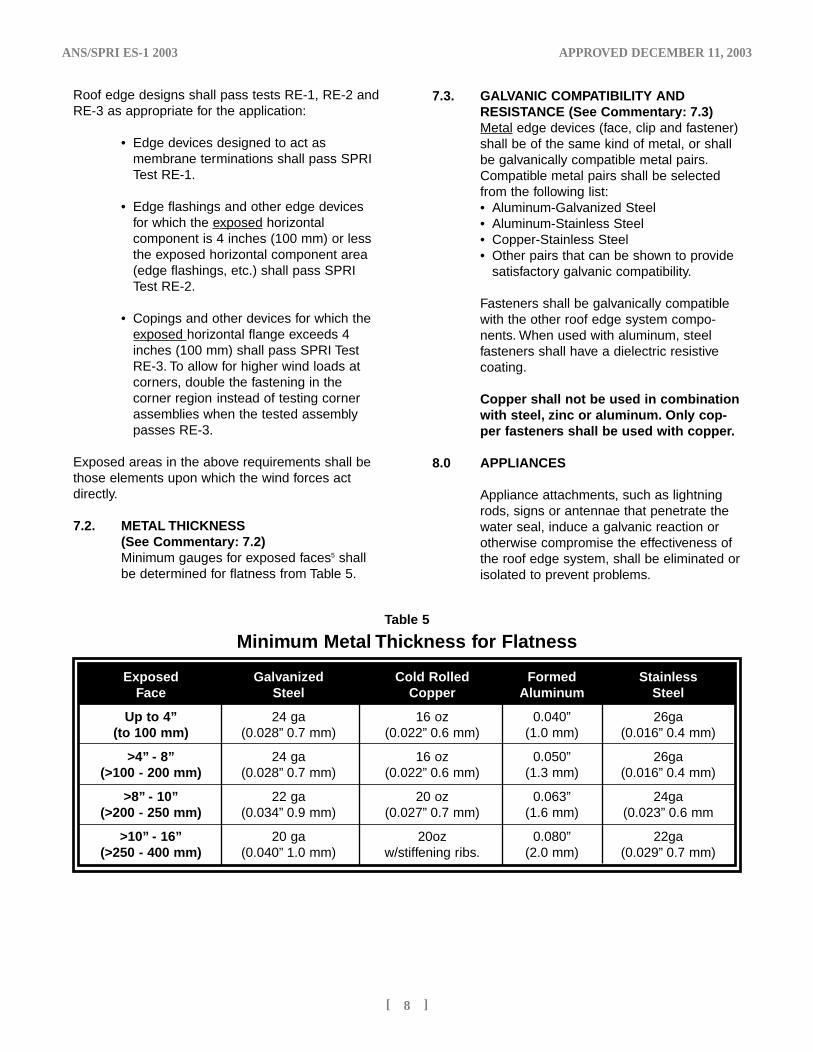
7.2. METAL THICKNESS (See Commentary: 7.2)Minimum gauges for exposed faces5 shallbe determined for flatness from Table 5.
7.3. GALVANIC COMPATIBILITY AND RESISTANCE (See Commentary: 7.3) Metal edge devices (face, clip and fastener)shall be of the same kind of metal, or shallbe galvanically compatible metal pairs.Compatible metal pairs shall be selectedfrom the following list:• Aluminum-Galvanized Steel• Aluminum-Stainless Steel• Copper-Stainless Steel• Other pairs that can be shown to provide
satisfactory galvanic compatibility.
Fasteners shall be galvanically compatiblewith the other roof edge system compo-nents. When used with aluminum, steel fasteners shall have a dielectric resistivecoating.
Copper shall not be used in combinationwith steel, zinc or aluminum. Only cop-per fasteners shall be used with copper.
8.0 APPLIANCES
Appliance attachments, such as lightningrods, signs or antennae that penetrate thewater seal, induce a galvanic reaction orotherwise compromise the effectiveness ofthe roof edge system, shall be eliminated orisolated to prevent problems.
Table 5
Minimum Metal Thickness for Flatness
Exposed Galvanized Cold Rolled Formed Stainless Face Steel Copper Aluminum Steel
Up to 4” 24 ga 16 oz 0.040” 26ga(to 100 mm) (0.028” 0.7 mm) (0.022” 0.6 mm) (1.0 mm) (0.016” 0.4 mm)
>4” - 8” 24 ga 16 oz 0.050” 26ga(>100 - 200 mm) (0.028” 0.7 mm) (0.022” 0.6 mm) (1.3 mm) (0.016” 0.4 mm)
>8” - 10” 22 ga 20 oz 0.063” 24ga(>200 - 250 mm) (0.034” 0.9 mm) (0.027” 0.7 mm) (1.6 mm) (0.023” 0.6 mm
>10” - 16” 20 ga 20oz 0.080” 22ga(>250 - 400 mm) (0.040” 1.0 mm) w/stiffening ribs. (2.0 mm) (0.029” 0.7 mm)
ES-1'04 4/10/04 1:26 AM Page 15
ANS/SPRI ES-1 2003 APPROVED DECEMBER 11, 2003
[ 9 ]
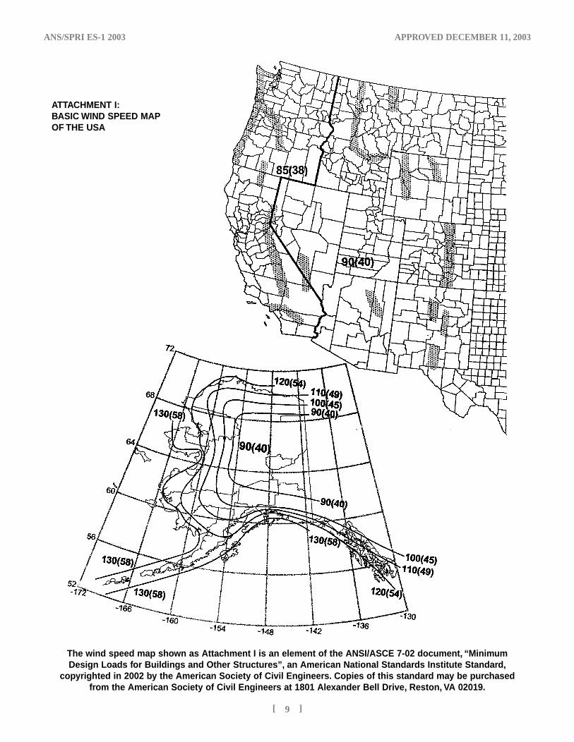
ATTACHMENT I:BASIC WIND SPEED MAP OF THE USA
The wind speed map shown as Attachment I is an element of the ANSI/ASCE 7-02 document, “MinimumDesign Loads for Buildings and Other Structures”, an American National Standards Institute Standard,
copyrighted in 2002 by the American Society of Civil Engineers. Copies of this standard may be purchasedfrom the American Society of Civil Engineers at 1801 Alexander Bell Drive, Reston, VA 02019.
ES-1'04 4/10/04 1:26 AM Page 18
ANS/SPRI ES-1 2003 APPROVED DECEMBER 11, 2003
[ 1 0 ]
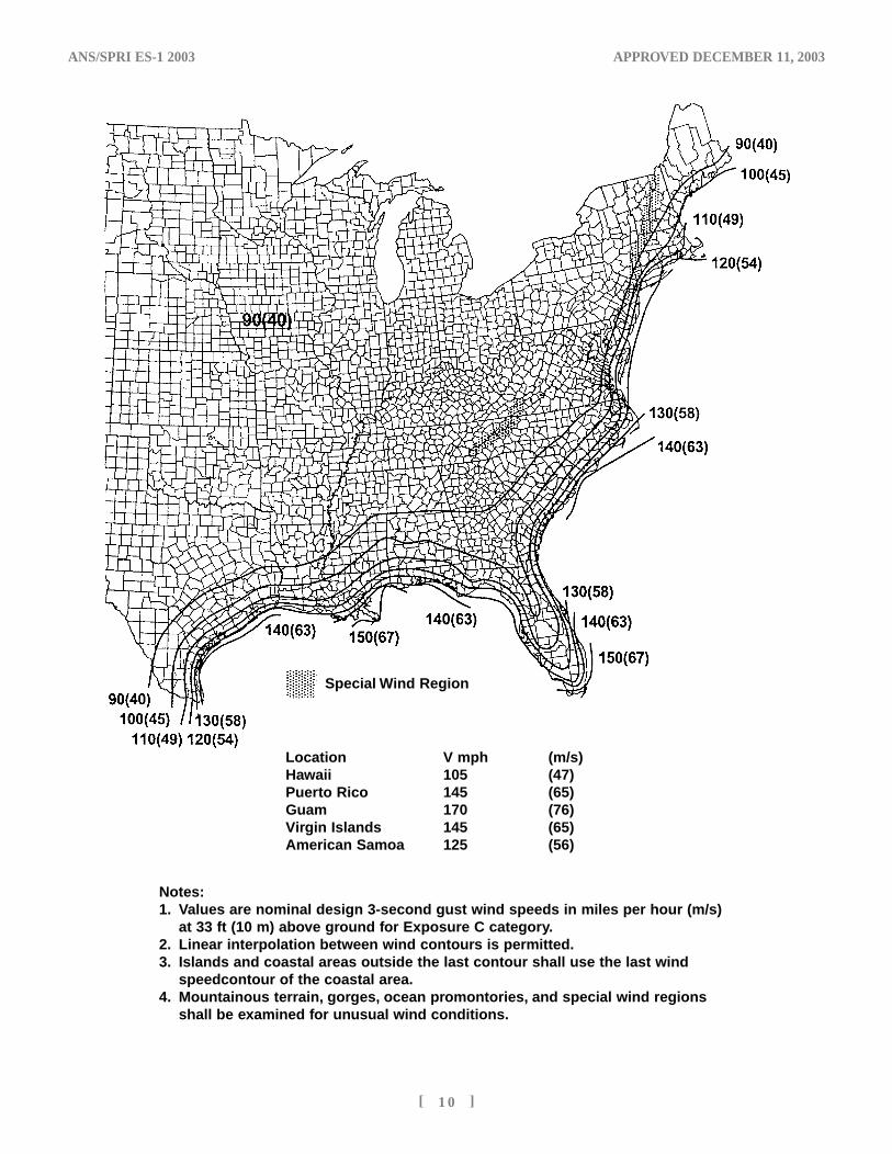
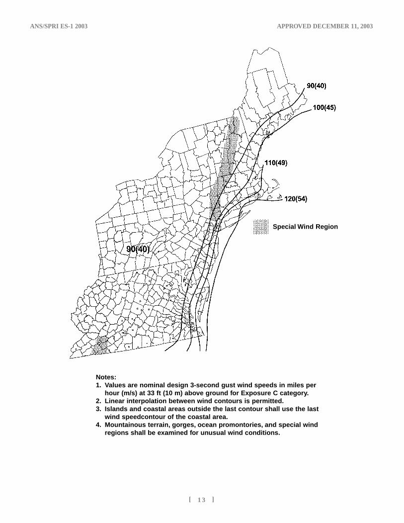
Notes:1. Values are nominal design 3-second gust wind speeds in miles per hour (m/s)
at 33 ft (10 m) above ground for Exposure C category.2. Linear interpolation between wind contours is permitted.3. Islands and coastal areas outside the last contour shall use the last wind
speedcontour of the coastal area.4. Mountainous terrain, gorges, ocean promontories, and special wind regions
shall be examined for unusual wind conditions.
Location V mph (m/s)Hawaii 105 (47)Puerto Rico 145 (65)Guam 170 (76)Virgin Islands 145 (65)American Samoa 125 (56)
Special Wind Region
ES-1'04 4/10/04 1:26 AM Page 19
ANS/SPRI ES-1 2003 APPROVED DECEMBER 11, 2003
[ 1 1 ]
No
tes:
1.V
alu
es a
re n
om
inal
des
ign
3-s
eco
nd
gu
st
win
d s
pee
ds
in m
iles
per
ho
ur
(m/s
) at
33
ft
(10
m)
abov
e g
rou
nd
fo
r E
xpo
sure
C c
ateg
ory
.2.
Lin
ear
inte
rpo
lati
on
bet
wee
n w
ind
co
nto
urs
is p
erm
itte
d.
3.Is
lan
ds
and
co
asta
l are
as o
uts
ide
the
last
co
nto
ur
shal
l use
th
e la
st w
ind
sp
eed
co
nto
ur
of
the
coas
tal a
rea.
4.M
ou
nta
ino
us
terr
ain
,go
rges
,oce
anp
rom
on
tori
es,a
nd
sp
ecia
l win
d r
egio
ns
shal
l b
e ex
amin
ed f
or
un
usu
al w
ind
co
nd
itio
ns.
Sp
ecia
l Win
d R
egio
n
ES-1'04 4/10/04 1:30 AM Page 22
ANS/SPRI ES-1 2003 APPROVED DECEMBER 11, 2003
[ 1 2 ]
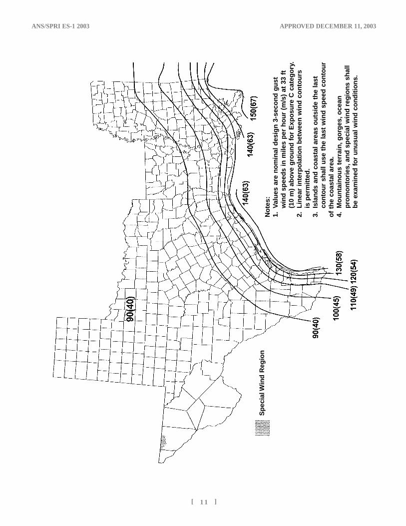
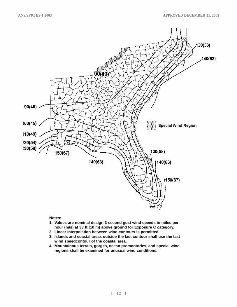
Notes:1. Values are nominal design 3-second gust wind speeds in miles per
hour (m/s) at 33 ft (10 m) above ground for Exposure C category.2. Linear interpolation between wind contours is permitted.3. Islands and coastal areas outside the last contour shall use the last
wind speedcontour of the coastal area.4. Mountainous terrain, gorges, ocean promontories, and special wind
regions shall be examined for unusual wind conditions.
Special Wind Region
ES-1'04 4/10/04 1:26 AM Page 23
ANS/SPRI ES-1 2003 APPROVED DECEMBER 11, 2003
[ 1 3 ]
Notes:1. Values are nominal design 3-second gust wind speeds in miles per
hour (m/s) at 33 ft (10 m) above ground for Exposure C category.2. Linear interpolation between wind contours is permitted.3. Islands and coastal areas outside the last contour shall use the last
wind speedcontour of the coastal area.4. Mountainous terrain, gorges, ocean promontories, and special wind
regions shall be examined for unusual wind conditions.
Special Wind Region
ES-1'04 4/10/04 1:26 AM Page 26
ANS/SPRI ES-1 2003 APPROVED DECEMBER 11, 2003
[ 1 4 ]
(See Commentary: SPRI Test Method RE-1)
• Fully adhered systems or systems using an alternative method of terminating the roof at the edge shall not require this test.
• For ballasted roofs, the edge device assembly shall provide a minimum load resistance (F) of 100 lbs/Ft (134 kg/m).
F = 100 for ballasted roofs• For mechanically attached systems the
distance (D) of the first row of fasteners parallel to the edge away from corner regions, and distance (Dcorner) of the first row of fasteners parallel to the edge in the building corner regions shall be used in the following equations to determine the load resistance which shallbe the greater of:
F= (D) (P) ÷2 and Fcorner = 1.5(Dcorner)(P) ÷2
The edge device assembly shall provide a minimum load resistance which is the maximum of F or Fcorner.
Testing: Load resistance shall be tested using thefollowing method.
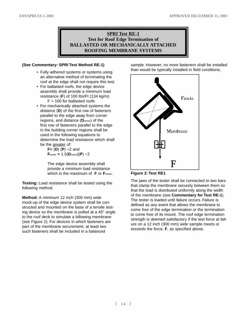
Method: A minimum 12 inch (300 mm) widemock-up of the edge device system shall be con-structed and mounted on the base of a tensile test-ing device so the membrane is pulled at a 45° angleto the roof deck to simulate a billowing membrane(see Figure 2). For devices in which fasteners arepart of the membrane securement, at least twosuch fasteners shall be included in a balanced
sample. However, no more fasteners shall be installedthan would be typically installed in field conditions.
The jaws of the tester shall be connected to two barsthat clamp the membrane securely between them sothat the load is distributed uniformly along the widthof the membrane (see Commentary for Test RE-1).The tester is loaded until failure occurs. Failure isdefined as any event that allows the membrane tocome free of the edge termination or the terminationto come free of its mount. The roof edge terminationstrength is deemed satisfactory if the test force at fail-ure on a 12 inch (300 mm) wide sample meets orexceeds the force, F, as specified above.
SPRI Test RE-1Test for Roof Edge Termination of
BALLASTED OR MECHANICALLY ATTACHED ROOFING MEMBRANE SYSTEMS
Figure 2: Test RE1
ES-1'04 4/10/04 1:26 AM Page 27
ANS/SPRI ES-1 2003 APPROVED DECEMBER 11, 2003
[ 1 5 ]
SPRI Test RE-2Pull-Off Test for Edge flashings
Exposed horizontal component is 4 inches (100 mm) or less
(See Commentary: SPRI Test Method RE-2)
1. Apparatus
The description of the apparatus is generalin nature. Any equipment capable of per-forming the test procedure within theallowed tolerances shall be permitted. Aschematic drawing of this apparatus isshown in Figure 3. The test apparatus shallbe constructed so that the performance ofindividual components are unaffected byedge or end constraints on the test sample.
2. Safety Precautions
Proper precautions shall be taken to protectthe operating personnel and observers incase of any failure.
3. Test Specimens
All parts of the test specimen shall be fullsize in width and all other dimensions,using the same materials, details and meth-ods of construction and anchoring devices(such as clips or cleats) as used on theactual building. Sample length shall be theaverage length designed for field use on theproject with a minimum of 8 feet (2.4 m).When the longest length designed for theproject is less than 8 feet (2.4 m) thelongest design length shall be used. Whenthe anchoring means at the ends of theedge flashing are normally used to restrainother additional lengths of edge flashing,then the anchoring means shall be modifiedso that only that percentage that mightrestrain rotational movement in the testspecimen is used.
4. Procedure
4.1 GravityAny undue influence from gravity that doesnot occur during actual installation shall beomitted from the test specimen. If the testspecimen is inverted, a gravity correction
shall be made in the determination of theallowable superimposed loading. Tests runin an inverted position shall include datafrom pressure reversal or an upright specimen to show that unlatching at thedrip edges will not occur in the normal orientation.
4.2 StabilizationA dial gauge shall be attached to the cen-terline of each loaded surface to detectmovement. Stabilization of the test shall bewhen the gauge ceases to show move-ment.
4.3 LoadingLoading shall be applied uniformly on cen-ters no greater than 12 inches (300 mm) tothe center-line of the vertical face of theedge flashing. Loading shall be applied onthe horizontal centerline of the face. Loadsshall be applied incrementally and held fornot less than 60 seconds after stabilizationhas been achieved at each incrementalload. Between incremental loads, the load-ing shall be reduced to zero until the speci-men stabilizes, or for five minutes, whichev-er happens first. After a recovery period ofnot more than five minutes at zero load, ini-tiate the next higher incremental load.Loading to the face of the edge flashingshall be applied in increments not toexceed 25-lb/SqFt. (120 kg/m2) until approx-imately 150-lb/SqFt. (730-kg/m2) isobtained. Thereafter, increments of loadshall not exceed 10-lb/SqFt. (50-kg/m2).Loading speed shall be such that eachincremental load up to and including 150-lb/SqFt. (730-kg/m2) shall be achieved in 60seconds or less. Above 150-lb/SqFt. (730-kg/m2), incremental loading shall beachieved in 120 seconds or less.
Loading shall proceed as indicated until thetest specimen either fails or exceeds therequired design pressure. The incrementsof load application shall be chosen so that
ES-1'04 4/10/04 1:26 AM Page 28
ANS/SPRI ES-1 2003 APPROVED DECEMBER 11, 2003
[ 1 6 ]
a sufficient number of observations aremade to determine the exact load at failure.The last sustained 60-second load withoutfailure is the maximum load recorded as thedesign value.
4.4 FailureFailure shall be loss of securement of anycomponent of the roof edge system ordeformation that would result in loss ofweather protection of the edge.
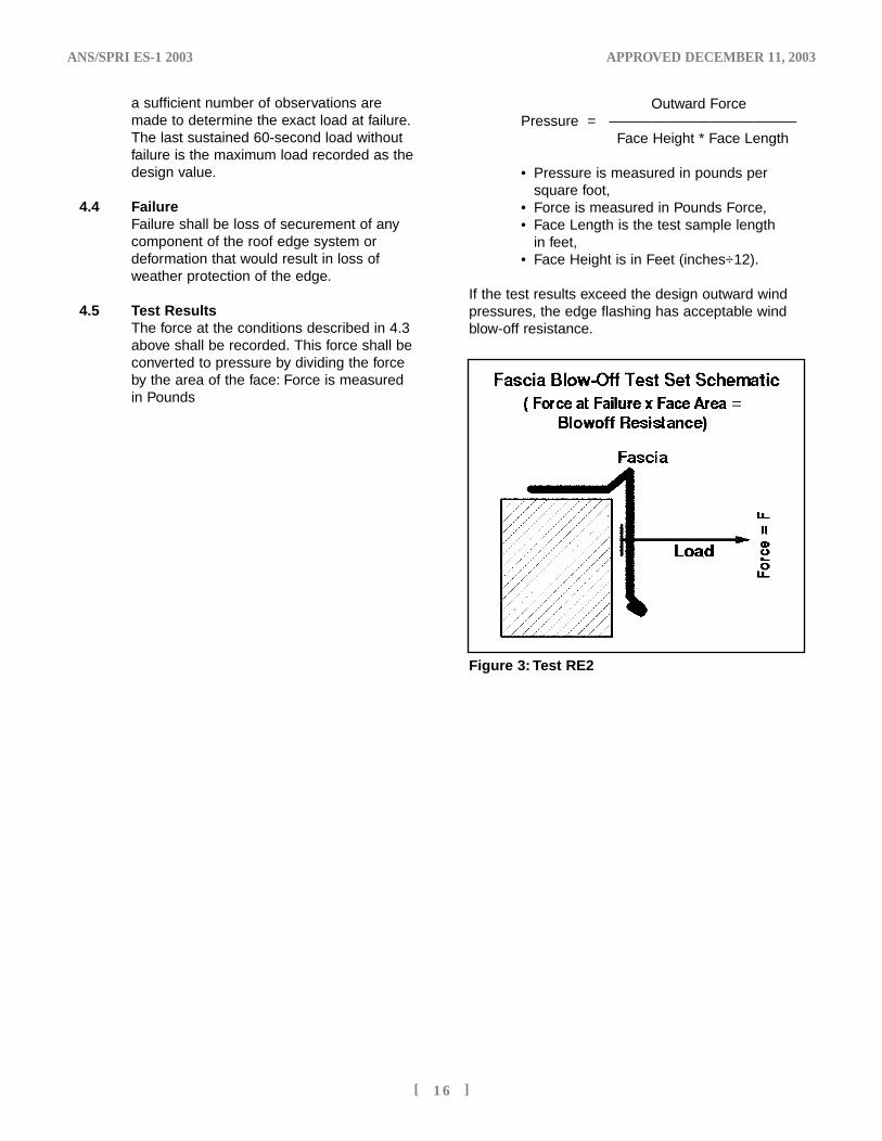
4.5 Test ResultsThe force at the conditions described in 4.3above shall be recorded. This force shall beconverted to pressure by dividing the forceby the area of the face: Force is measuredin Pounds
Outward ForcePressure = —————————————
Face Height * Face Length
• Pressure is measured in pounds per square foot,
• Force is measured in Pounds Force, • Face Length is the test sample length
in feet, • Face Height is in Feet (inches÷12).
If the test results exceed the design outward windpressures, the edge flashing has acceptable windblow-off resistance.
Figure 3: Test RE2
ES-1'04 4/10/04 1:26 AM Page 25
(See Commentary: SPRI Test Method RE-3)
1. Apparatus
This description of the apparatus is generalin nature. Any equipment capable of per-forming the test procedure within theallowed tolerances shall be permitted. Aschematic drawing of this apparatus isshown in Figures 4 and 5. The test appara-tus shall be constructed so that the per-formance of individual components areunaffected by edge or end constraints onthe test sample.
2. Safety Precautions
Proper precautions shall be taken to protectthe operating personnel and observers incase of any failure.
3. Test Specimens
All parts of the test specimen shall be fullsize in width and all other dimensions,using the same materials, details and meth-ods of construction and anchoring devices(such as clips or cleats) as used on theactual building. Sample length shall be theaverage length designed for field use on the
ANS/SPRI ES-1 2003 APPROVED DECEMBER 11, 2003
[ 1 7 ]
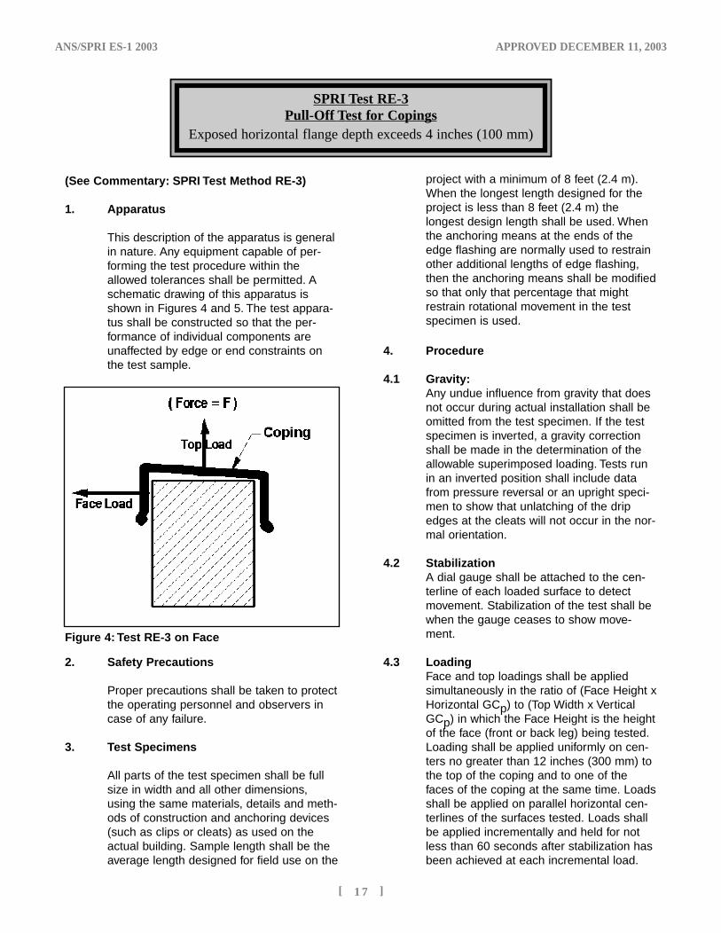
SPRI Test RE-3Pull-Off Test for Copings
Exposed horizontal flange depth exceeds 4 inches (100 mm)
Figure 4: Test RE-3 on Face
project with a minimum of 8 feet (2.4 m).When the longest length designed for theproject is less than 8 feet (2.4 m) thelongest design length shall be used. Whenthe anchoring means at the ends of theedge flashing are normally used to restrainother additional lengths of edge flashing,then the anchoring means shall be modifiedso that only that percentage that mightrestrain rotational movement in the testspecimen is used.
4. Procedure
4.1 Gravity:Any undue influence from gravity that doesnot occur during actual installation shall beomitted from the test specimen. If the testspecimen is inverted, a gravity correctionshall be made in the determination of theallowable superimposed loading. Tests runin an inverted position shall include datafrom pressure reversal or an upright speci-men to show that unlatching of the dripedges at the cleats will not occur in the nor-mal orientation.
4.2 StabilizationA dial gauge shall be attached to the cen-terline of each loaded surface to detectmovement. Stabilization of the test shall bewhen the gauge ceases to show move-ment.
4.3 LoadingFace and top loadings shall be appliedsimultaneously in the ratio of (Face Height xHorizontal GCp) to (Top Width x VerticalGCp) in which the Face Height is the heightof the face (front or back leg) being tested.Loading shall be applied uniformly on cen-ters no greater than 12 inches (300 mm) tothe top of the coping and to one of thefaces of the coping at the same time. Loadsshall be applied on parallel horizontal cen-terlines of the surfaces tested. Loads shallbe applied incrementally and held for notless than 60 seconds after stabilization hasbeen achieved at each incremental load.
ES-1'04 4/10/04 1:26 AM Page 24
Between incremental loads, the loadingshall be reduced to zero until the specimenstabilizes, or for five minutes, whicheverhappens first. After a recovery period of notmore than five minutes at zero load, initiatethe next higher incremental load. Loading tothe top of the coping shall be applied inincrements not to exceed 25-lb/SqFt (120kg/m2) until approximately 150-lb/SqFt (730kg/m2) is obtained. Thereafter, incrementsof load shall not exceed 10-lb/SqFt (5kg/m2). Loading speed shall be such thateach incremental load up to and including150 lb/SqFt (730 kg/m2) shall be achievedin 60 seconds or less. Above 150-lb/SqFt(730 kg/m2), incremental loading shall beachieved in 120 seconds or less.
Loading shall proceed as indicated until thetest specimen either fails or exceeds therequired design pressure. The incrementsof load application shall be chosen so thata sufficient number of observations aremade to determine the exact load at failure.The last sustained 60-second load withoutfailure is the maximum load recorded as thedesign value.
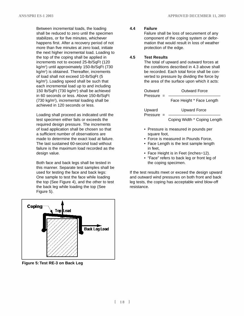
Both face and back legs shall be tested inthis manner. Separate test samples shall beused for testing the face and back legs:One sample to test the face while loadingthe top (See Figure 4), and the other to testthe back leg while loading the top (SeeFigure 5).
ANS/SPRI ES-1 2003 APPROVED DECEMBER 11, 2003
[ 1 8 ]
Figure 5: Test RE-3 on Back Leg
4.4 FailureFailure shall be loss of securement of anycomponent of the coping system or defor-mation that would result in loss of weatherprotection of the edge.
4.5 Test ResultsThe total of upward and outward forces atthe conditions described in 4.3 above shallbe recorded. Each total force shall be con-verted to pressure by dividing the force bythe area of the surface upon which it acts:
Outward Outward ForcePressure = —————————————
Face Height * Face Length
Upward Upward ForcePressure = —————————————
Coping Width * Coping Length
• Pressure is measured in pounds per square foot,
• Force is measured in Pounds Force, • Face Length is the test sample length
in feet, • Face Height is in Feet (inches÷12).• “Face” refers to back leg or front leg of
the coping specimen.
If the test results meet or exceed the design upwardand outward wind pressures on both front and backleg tests, the coping has acceptable wind blow-offresistance.
ES-1'04 4/10/04 1:26 AM Page 21
ANS/SPRI ES-1 2003 APPROVED DECEMBER 11, 2003
[ 1 9 ]
COMMENTARY toWIND DESIGN STANDARD for EDGE SYSTEMS USED with
LOW SLOPE ROOFING
This Commentary consists of explanatory and supplementary material designed to help designers,roofing contractors and local building authorities inapplying the requirements of the precedingStandard.
This Commentary is intended to create an under-standing of the requirements through brief explana-tions of the reasoning employed in arriving at theserequirements.
The sections of this Commentary are numbered tocorrespond to sections of the Standard to which theyrefer. Since having supplementary material for everysection of the Standard is not necessary, not all sections are referenced in this Commentary.
1. INTRODUCTIONThis Design Standard was developed foruse with Built-Up (BUR), Single-Ply andModified Bitumen roofing systems. While theStandard is intended as a reference fordesigners and roofing contractors, thedesign responsibility rests with the “designerof record.”
Roof edge systems serve aesthetic as wellas performance functions for a building.Aesthetically, they provide an attractive fin-ish and sometimes even a key feature to theexterior of a building. Of course, no matterhow aesthetically pleasing, a roof edge sys-tem must act primarily as an effectivemechanical termination and transitionbetween the roof and other building compo-nents such as parapet walls, vertical walls,corners, soffits, edge flashing boards, etc.
A high performance roof edge system pro-vides many benefits. It acts as a water sealat the edge. When it is also the means bywhich the membrane is attached to thebuilding at the edge, it must also exhibit suf-ficient holding power to prevent the mem-brane from pulling out at the edge underdesign wind conditions. Furthermore, theedge device assembly itself must not comeloose in a design wind. A loose edgeassembly not only endangers surrounding
property or persons, but it also exposes theroofing to blow-off, starting at the edge.
Perimeter systems considered for thisStandard are differentiated into two generaltypes:
COPINGS/CAPS: These are designs thatcover the tops of parapet walls, usually withthe roofing membrane terminated underthem.
EDGE FLASHINGS: These products ordesigns complete the horizontal deck ormembrane plane at its transition to a verti-cal wall drop, typically at a 90˚ angle.Normally the roofing membrane isrestrained at the edge by means of amechanical gripping of the roofing betweenmetal members or by a bond between theroofing and edging.
Termination devices against vertical wallsinboard of the roof edge are not consideredby this Guideline.
An edge flashing may also function as anair seal, when combined with an air-retarder throughout the field of the roof, bypreventing air infiltration under the roofingmembrane. To resist air infiltration, nailersshould be sealed to the building with appro-priate sealant material b. Where multiplecourses of nailers are used, these nailercourses should also be sealed to eachother. Butt joints should also be sealed.
GUTTERS: Gutters and other rain-carryingdevices are beyond the scope of thisStandard. However, the designer should beaware that their securement is important tothe proper functioning of the building.
Two general classes of materials covernearly all perimeter systems. They are:
EXTRUSIONS: Shapes or designs made byforcing heated metal or polymeric materialthrough pre-cut custom dies. These designs
ES-1'04 4/10/04 1:26 AM Page 20
ANS/SPRI ES-1 2003 APPROVED DECEMBER 11, 2003
[ 2 0 ]
are usually of a heavier gauge than formedproducts, but many extrusions must havetheir finish applied after manufacturing.
FORMED METAL: Sheets of metal, usuallysteel, aluminum or copper, bent on pressbrakes or roll-forming equipment to match adesired design or configuration. TheseConfigurations are available in many thick-nesses and frequently with a variety of fin-ishes.
MAINTENANCEThe design engineer should consider main-tenance of the roof edge. See theARMA/NRCA/SPRI Repair Manual for Low-Slope Roof Membrane Systems.6
SUMMARY This document addresses factors thatshould be considered in the specificationand design of roof edge systems for lowslope (≤ 10 degree slope) roofing systems.Good design practice requires considera-tion of nailer, roof edge and membranesecurement, and selection of materials andfinishes to minimize corrosion, and metalgauges to assure strength and flatness.
2.0 GENERAL DESIGN CONSIDERATIONSAND DEFINITIONSDetermination of the appropriate wind loadused in the design is based on wind speed,Exposure, building height, topography andthe edge detail location on the building.Location of the edge detail on the buildingis also important, since blow-off forcesincrease near the corners.
2.2 WIND SPEEDSpecial wind regions (mountains or valleys):Refer to Section 6.5.5 of the ANSI/ASCE 7-021 Commentary.
The intensifying effects of topography (hillsor escarpments) are to be accounted for.Speedup over hills and escarpments isaccounted for in ASCE 7-021 by means of atopographic factor, Kzt that depends on theheight of the building, the height and slopeof the hill or escarpment, the distance ofthe crest upwind of the building, andwhether the terrain is a hill or an escarp-ment.
2.4.1 Corner RegionThe angle at which the walls meet to consti-tute a corner is undefined here and inASCE 7-021. It has been suggested that anairflow separation effect begins to takeeffect when walls meet at 150°. Since mostwalls meet at angles more acute than this,the meeting angle is not a practical consid-eration for this Standard7. Because it is diffi-cult to test corner systems, the increasedwind forces on the component have beenaccounted for by recommending doubledfastening at the building corner regionsrather than testing corner componentsdirectly as such.
3.0 EXPOSUREThe terrain surrounding a building will influence the exposure of that building tothe wind.
4.0 IMPORTANCE FACTORThe Importance Factor, I, accounts for thedegree of hazard to human life and damageto property. The Importance Factor, I, isused to modify the wind speed and, ineffect, assign different levels of risk basedupon intended use of the structure.Category I Exposure gives a 25-year meanrecurrence value while Categories III and IVgive 100-year mean recurrence values.Other recurrence values can be found in theCommentary of ASCE 7-021.
5.0 SYSTEM REQUIREMENTSResistance to blow-off depends not onlyupon the attachment of the roof edgedevice to the edge of the building, but alsoupon the integrity of the nailer or other substrate to which the edge device isattached. It is important to consider the load path from the nailer to the foundationof the building to assure proper wind loadprotection.
Common fastener safety factors appear inTable 6. Note that when designing for wind,static load safety factors may be reduced by 25%.
5.1 Nailer Secured SystemsWood Members: Nailers should be preser-vatively treated wood11 secured to structuralcomponents of the building by corrosion
b An appropriate sealant is a single- or multi-component elastomeric material used to weatherproof construction joints.
ES-1'04 4/10/04 1:26 AM Page 17
resistant12 means sufficient to resist a verti-cal load of 200 lbf/Ft (300 kg/m) or thedesign load, whichever is greater. For woodnailers wider than 6 inches (152 mm), boltsshould be staggered to avoid splitting thewood. Each wood nailer member shouldhave at least two fasteners. A fastenershould be located approximately 4 inches(100 mm) but not less than 3 inches (75mm) from each end of the wood. Additionalwood members, such as cant strips andstacked nailers should be fastened with cor-rosion resistant fasteners having sufficientpullout resistance. Fasteners should bestaggered, spaced at a maximum 12 inches(305 mm) on centers, and should penetrate
the wood sufficiently to achieve design pull-out resistance. Spacing should be on maxi-mum 6 inch (152 mm) centers in cornerregions of the building.
When Re-roofing, the existing nailer shouldbe exposed and inspected. If it has deterio-rated, is should be replaced.
Masonry: When embedded in masonry,anchor bolts as defined above should bebent 90 degrees at the base or have headsdesigned to prevent rotation and slippingout. When hollow block masonry is used atthe roofline, cores and voids in the top rowof blocks should be filled with concrete hav-ing a minimum density of 140-lbs/cu ft(10,900 g/m3). When embedded in light-weight aggregate hollow block, bolts shouldbe embedded minimum 12 inches (300mm) into concrete fill. When heavy aggre-gate blocks are used, bolts should beembedded minimum 8 inches (200 mm).
Light Weight Concrete And GypsumDecks: Nailers should not be fastened tolight weight concrete or gypsum decks.Instead, anchor all roof perimeter nailersdirectly to building structural members
ANS/SPRI ES-1 2003 APPROVED DECEMBER 11, 2003
[ 2 1 ]
using fasteners whose size and locationsmeet provisions in Section 5.1 of theStandard.
Steel Deck: The steel deck should bedesigned to withstand the design forcesspecified under Section 5.1 of the Standard.Nailer attachment should be strong enoughto resist 200-bf/Ft (300 kg/m) vertical load.
Nailerless Systems: When the roof edge isattached directly to masonry or steel withoutthe use of a nailer, its attachment configura-tion should be tested to resist wind loading,using tests specified in Section 6 of thisStandard.
Reroofing: For nailer security when reroof-ing, the contractor should check to be surethe nailer or other substrate is in good con-dition and well secured to the building.Questionable members should be removedand replaced according to the above guide-lines. Note that it is much more difficult tobe sure that the load path (connection ofroof members ultimately to the buildingfoundation) is secure for an existing buildingthan it is for new construction. The roofingcontractor should notify the designer ifunexpected conditions or deteriorated sub-strate materials are discovered during thereroofing process.
6.0 DESIGN OPTIONSLoad Resistance of the edge detail is divid-ed into two considerations. The first is theresistance of the edge to outward andupward forces that tend to blow or peel theedge system off the substrate. The secondis the ability of the edge to resist the pull ofthe roofing inwardly.
Edge details may be selected from manu-facturers who certify certain minimum per-formance to meet design requirements,based upon testing. Other designs may beused, provided they are tested and certifiedby an independent testing laboratory tomeet the wind and pullout resistance designstandards suggested in this document.
6.1 MEMBRANE ATTACHMENTThe edge flashing may be the only restraintpreventing a roof blow-off. In ballasted sys-tems, ballast may be scoured away from theedge. Mechanically attached membranes
Safety FactorSubstrate
Static Load Wind Load
Wood8 6.0 4.5
Masonry9 4.0 3.0
Steel10 2.5 1.9
Table 6
ES-1'04 4/10/04 1:26 AM Page 16
ANS/SPRI ES-1 2003 APPROVED DECEMBER 11, 2003
[ 2 2 ]
may be attached only by the edge flashingat the building edge. The 100 lb/Ft (1.46kN/m) may not be sufficient if there isexcessive scour, exposing a wide span ofroofing. Ballasted roofs should be designedto meet ANSI/SPRI RP-4 to prevent exces-sive scour.
Consideration should be given to sealingthe edge against air infiltration. Air infiltra-tion may affect the loads on the roofing andthe perimeter edge detail14 by adding a pos-itive pressure under the roofing, thus com-pounding the effect of negative pressureabove the roofing.
Modified Bitumen and BUR membranesshould be fully adhered to roof deck orinsulation.
6.2 WIND RESISTANCE OF EDGE & 6.3 FLASHINGS & COPINGS
Although all edge devices are to be testedaccording to the tests outlined in theStandard and its attachments, the followingguidelines may be used to establishdesigns for testing. The guidelines may bemodified to achieve desired test results.
Edge flashings, copings and the like shouldbe secured with continuous cleats of mini-mum 24 ga steel, 0.050 inch (2 mm) alu-minum or metal of equivalent tensilestrength at the bottom of the face edge.Cleats should be secured with annularthreaded or ring-shank nails long enough topenetrate the wood nailer at least 1-1/4inch (3 cm). Nail heads should be at least3/16 inch (5 mm) in diameter. Alternatively,cleats may be secured with minimum No. 8(4 mm) screws long enough to penetratethe nailer 3/4 inch (20 mm) or penetratemetal 3/8 inch (10 mm). Where velocitypressures are less than 45 lbs/Ft2 (220kg/m2), cleat fasteners should be placed nofarther than 24” (600 mm) apart. Wherevelocity pressures are greater than 45lbs/Ft2 (220 kg/m2) they should be spaced16” (400 mm) or closer. Fastener frequencyshould be doubled in building cornerregions.
Metal coping should be secured by a cleatat the wall exterior. Where velocity pres-sures exceed 45 psf (220 kg/m2), the cop-
ing should be secured on the inside withNo. 10 (5 mm) galvanized screw fastenersthrough neoprene washers on 30 inch (760mm) or narrower centers. At higher velocitypressures, the centers should be 20 inch(500 mm) or narrower. Screws should belong enough to penetrate the wood nailer atleast 1 inch (25 mm). The effects of thermalexpansion should be considered. Screwholes in the coping should be pre-punchedor drilled oversize to allow for thermalexpansion. Edge flashing sections shouldbe spaced to allow for expansion.
To ensure adequate holding, edge designsshould also include a drip edge that secure-ly engages the cleat. Inadequate secure-ment may lead to a release of the edge,resulting in the ultimate failure of the roofedge device.
Fastener spacing is doubled in building cor-ner regions to account for the increasedwind forces in these regions.
7.0 DESIGN PROVISIONS
7.1 WIND RESISTANCETABLE 4 values have been calculated usingEquation 6-15 from ASCE 7-021
qz = 0.00256(Kz)(Kzt)(V2)(I)in which:qz = Velocity Pressure (the Velocity
Pressures shown in Table 4 of this Standard are actually “ qz /I” as defined in ASCE 7-02 and therefore are to be multiplied by I to obtain qz.
Kz = Velocity Pressure Exposure Coefficient from Equation C6-3 in the Commentary Section of ASCE 7-02 (Also shown as Table 6-3 in ASCE 7-02),
Kzt = Topographical factor for buildings built on hills or escarpments (from Equation 6-3 of ASCE 7-02),
V = Basic Wind Speed, mph, from Attachment I of this Standard and
I = Importance factor defined in Table 1.
Velocity Pressure “qz” is the pressureimparted by the energy of the wind. In prac-
ES-1'04 4/10/04 1:26 AM Page 13
ANS/SPRI ES-1 2003 APPROVED DECEMBER 11, 2003
[ 2 3 ]
tice, aerodynamics will cause actual windpressures to differ from theoretical values atcertain locations on the building. A buildingwith a flat, level (or slightly sloped) roof willexperience greater forces at the corners andeaves than on interior roof surfaces becauseof eddy effects at the eaves. These effectsare accounted for by using the ExternalPressure Coefficient obtained from Table 3,which is taken from ASCE 7-021 assumingan effective wind area of 10 square feet orless. The precise sources for these data areshown on Table 7:The vertical component was taken from thevalues for Surface 2 on those Figures.ASCE 7-021 does not address the horizontalcomponent of GCp at the roof edge.Therefore, the horizontal value of GCp wastaken from the values for Surface 5, which isthe vertical corner region. That surface wasselected because it presents nearly thesame geometry to the wind, as would theroof edge. ASCE 7-021 suggests differentExternal Pressure Coefficients to be used inbuilding corner regions. Instead of usingASCE 7-021 values for these corner regionsin this Standard, the design method wassimplified by requiring doubled fastening inthese regions.
7.2 METAL THICKNESSIncreased metal thickness improves the flat-ness reduces the “oil-can” effect of the roofedge metal. The required minimums do notaddress other important design factors suchas fastening pattern and frequency, continu-ous or intermittent cleating, stiffening ribs orbreaks in the edges. Metal thickness may
need to be increased for higher wind areasunless Test RE-2 or RE-3 has been per-formed. Table 5 was developed from NRCAand Factory Mutual and SMACNA5 recom-mendations. The table has been construct-ed to simplify its use over the FactoryMutual table and to extend the range of fas-cia widths beyond that given by NRCA.
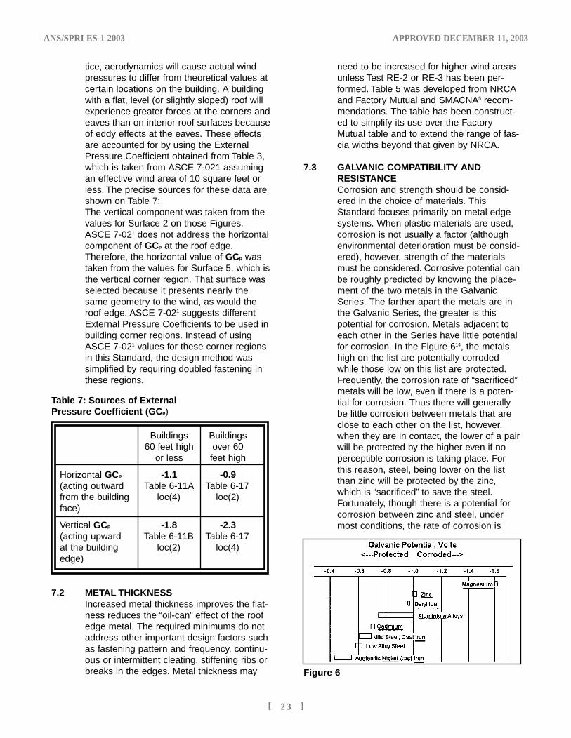
7.3 GALVANIC COMPATIBILITY AND RESISTANCECorrosion and strength should be consid-ered in the choice of materials. ThisStandard focuses primarily on metal edgesystems. When plastic materials are used,corrosion is not usually a factor (althoughenvironmental deterioration must be consid-ered), however, strength of the materialsmust be considered. Corrosive potential canbe roughly predicted by knowing the place-ment of the two metals in the GalvanicSeries. The farther apart the metals are inthe Galvanic Series, the greater is thispotential for corrosion. Metals adjacent toeach other in the Series have little potentialfor corrosion. In the Figure 614, the metalshigh on the list are potentially corrodedwhile those low on this list are protected.Frequently, the corrosion rate of “sacrificed”metals will be low, even if there is a poten-tial for corrosion. Thus there will generallybe little corrosion between metals that areclose to each other on the list, however,when they are in contact, the lower of a pairwill be protected by the higher even if noperceptible corrosion is taking place. Forthis reason, steel, being lower on the listthan zinc will be protected by the zinc,which is “sacrificed” to save the steel.Fortunately, though there is a potential forcorrosion between zinc and steel, undermost conditions, the rate of corrosion is
Table 7: Sources of External Pressure Coefficient (GCp)
Buildings Buildings60 feet high over 60
or less feet high
Horizontal GCp -1.1 -0.9(acting outward Table 6-11A Table 6-17from the building loc(4) loc(2)face)
Vertical GCp -1.8 -2.3(acting upward Table 6-11B Table 6-17at the building loc(2) loc(4)edge)
Figure 6
ES-1'04 4/10/04 1:26 AM Page 12
ANS/SPRI ES-1 2003 APPROVED DECEMBER 11, 2003
[ 2 4 ]
minuscule so that the zinc lasts many yearswhile electrolytically protecting the steel.
Similarly, pairs of metals such as aluminumand zinc or aluminum and stainless steelwill show no perceptible corrosion betweenthem, because of their proximity to eachother on the list. On the other hand, pairingcopper with zinc or aluminum or even steel
must be avoided because copper is far fromthem on the Galvanic Series and the poten-tial for corrosion is great.
In extremely corrosive environments suchas salt-water environments, chemical plantsor paper mills, corrosion resistant materialssuch as stainless steel shall be used.
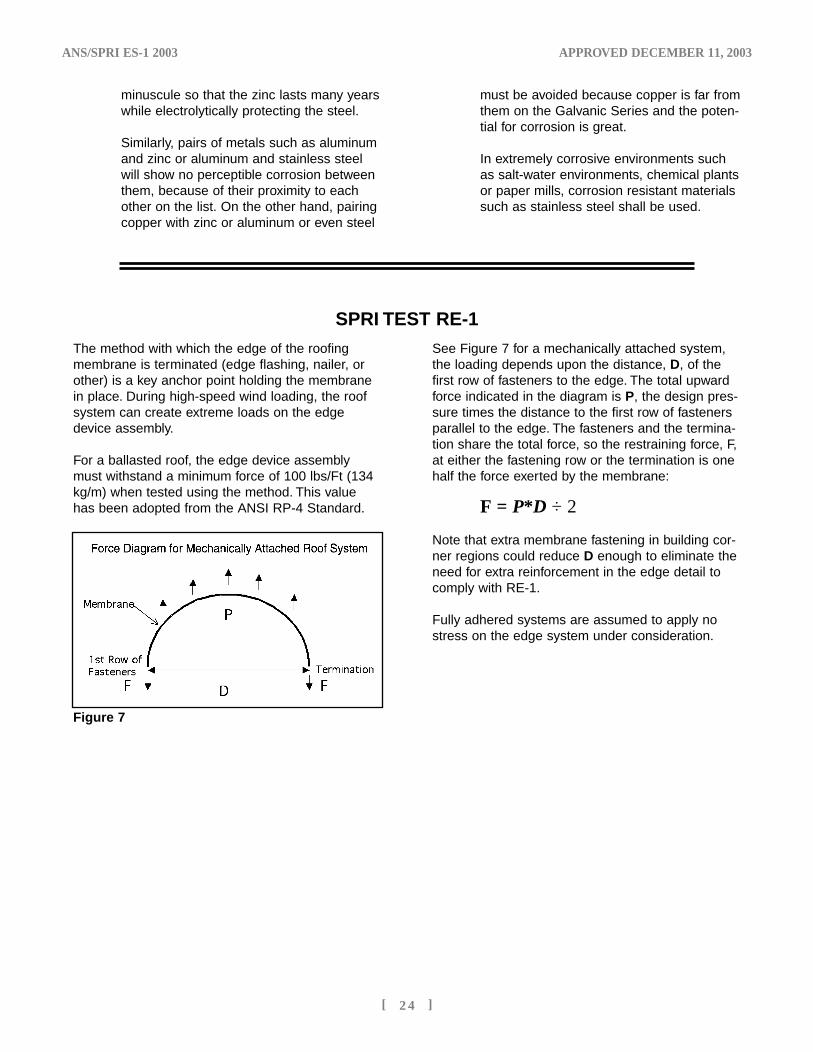
SPRI TEST RE-1See Figure 7 for a mechanically attached system,the loading depends upon the distance, D, of thefirst row of fasteners to the edge. The total upwardforce indicated in the diagram is P, the design pres-sure times the distance to the first row of fastenersparallel to the edge. The fasteners and the termina-tion share the total force, so the restraining force, F,at either the fastening row or the termination is onehalf the force exerted by the membrane:
F = P*D ÷ 2
Note that extra membrane fastening in building cor-ner regions could reduce D enough to eliminate theneed for extra reinforcement in the edge detail tocomply with RE-1.
Fully adhered systems are assumed to apply nostress on the edge system under consideration.
Figure 7
The method with which the edge of the roofingmembrane is terminated (edge flashing, nailer, orother) is a key anchor point holding the membranein place. During high-speed wind loading, the roofsystem can create extreme loads on the edgedevice assembly.
For a ballasted roof, the edge device assemblymust withstand a minimum force of 100 lbs/Ft (134kg/m) when tested using the method. This valuehas been adopted from the ANSI RP-4 Standard.
ES-1'04 4/10/04 1:26 AM Page 9
ANS/SPRI ES-1 2003 APPROVED DECEMBER 11, 2003
[ 2 5 ]
TEST METHODS RE-2 and RE-34.2 Stabilization
Stabilization is necessary during loading toensure that the specimen has reachedequilibrium before considering a sustainedload for a period of 60 seconds. As thespecimen approaches its ultimate capacity,stabilization of the specimen will generallytake longer to achieve.
4.3 LoadingThese test methods consist of applyingloads on surfaces of a test specimen andobserving deformations and the nature ofany failures of principal or critical elementsof the coping or edge flashing system pro-files or members of the anchor systems.Loads are applied to simulate the staticwind loading of the members. Test RE-2, foredge flashings, requires horizontal loadingon only the vertical face since the upwardwind loading on an edge flashing memberis considered to be negligible because ofthe small area exposed to uplift.
Since corners are difficult to test with thesemethods, corner areas are best handled bydesigning a device to pass RE-2 or RE-3 asappropriate and doubling the number of fas-teners in building corner regions.
A recovery period between increases inincremental loading is allowed for the testspecimen to attempt to assume its originalshape prior to applying the next load level.
The rate of sustained loading can be a criti-cal issue when specimens are subjected tocontinuously increasing load until failure is
achieved. Loading rate has little meaning inRE-2 and RE-3 because these methodsemploy incrementally increased loads sus-tained for relatively long times followed bybrief recovery periods. This incrementalmethod is more stringent than continuousloading because of the requirement of hold-ing a load for 60 seconds.
The Standard requires full-length speci-mens because end conditions of discreetsections of copings and edge flashings canplay a profound role in the failure mode ofthe materials. Furthermore, those productshaving non-continuous cleating can exhibitdifferent performance under testing than inthe field if the cleats do not act upon theproducts as they would in the field. Forexample, if a product requiring two cleats ina 144 inch (5669 mm) length were testedas a 36 inch (914 mm) sample with onecleat, the cleat would act over a larger per-cent of the product than would be experi-enced in the field, rendering the results dif-ficult to translate to the field.
These are new procedures. The precisionand bias of these test measures have notbeen determined.
4.4 FailureSome examples of component failure thatwill not enable the edge flashing to performas designed would be:• Full nail pull-out at some point• Collapse of a cleat, fascia or cover• Disengagement of a face or coping at the
drip-edge
ES-1'04 4/10/04 1:26 AM Page 8
ANS/SPRI ES-1 2003 APPROVED DECEMBER 11, 2003
[ 2 6 ]
EXAMPLE
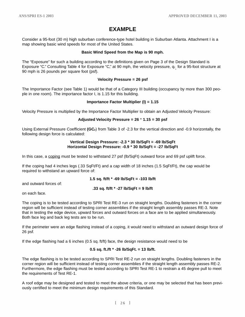
Consider a 95-foot (30 m) high suburban conference-type hotel building in Suburban Atlanta. Attachment I is amap showing basic wind speeds for most of the United States.
Basic Wind Speed from the Map is 90 mph.
The “Exposure” for such a building according to the definitions given on Page 3 of the Design Standard isExposure “C.” Consulting Table 4 for Exposure “C,” at 90 mph, the velocity pressure, qz, for a 95-foot structure at90 mph is 26 pounds per square foot (psf).
Velocity Pressure = 26 psf
The Importance Factor (see Table 1) would be that of a Category III building (occupancy by more than 300 peo-ple in one room). The importance factor I, is 1.15 for this building.
Importance Factor Multiplier (I) = 1.15
Velocity Pressure is multiplied by the Importance Factor Multiplier to obtain an Adjusted Velocity Pressure:
Adjusted Velocity Pressure = 26 * 1.15 = 30 psf
Using External Pressure Coefficient (GCp) from Table 3 of -2.3 for the vertical direction and -0.9 horizontally, thefollowing design force is calculated:
Vertical Design Pressure: -2.3 * 30 lb/SqFt = -69 lb/SqFtHorizontal Design Pressure: -0.9 * 30 lb/SqFt = -27 lb/SqFt
In this case, a coping must be tested to withstand 27 psf (lb/SqFt) outward force and 69 psf uplift force.
If the coping had 4 inches legs (.33 SqFt/Ft) and a cap width of 18 inches (1.5 SqFt/Ft), the cap would berequired to withstand an upward force of:
1.5 sq. ft/ft * -69 lb/SqFt = -103 lb/ftand outward forces of:
.33 sq. ft/ft * -27 lb/SqFt = 9 lb/fton each face.
The coping is to be tested according to SPRI Test RE-3 run on straight lengths. Doubling fasteners in the cornerregion will be sufficient instead of testing corner assemblies if the straight length assembly passes RE-3. Notethat in testing the edge device, upward forces and outward forces on a face are to be applied simultaneously.Both face leg and back leg tests are to be run.
If the perimeter were an edge flashing instead of a coping, it would need to withstand an outward design force of26 psf.
If the edge flashing had a 6 inches (0.5 sq. ft/ft) face, the design resistance would need to be
0.5 sq. ft./ft * -26 lb/SqFt. = 13 lb/ft.
The edge flashing is to be tested according to SPRI Test RE-2 run on straight lengths. Doubling fasteners in thecorner region will be sufficient instead of testing corner assemblies if the straight length assembly passes RE-2.Furthermore, the edge flashing must be tested according to SPRI Test RE-1 to restrain a 45 degree pull to meetthe requirements of Test RE-1.
A roof edge may be designed and tested to meet the above criteria, or one may be selected that has been previ-ously certified to meet the minimum design requirements of this Standard.
ES-1'04 4/10/04 1:26 AM Page 5
ANS/SPRI ES-1 2003 APPROVED DECEMBER 11, 2003
[ 2 7 ]
REFERENCES
1. Minimum Design Loads for Buildings and Other Structures, ASCE 7-02, American Society of Civil Engineers,New York, 2002.
2. National Design Specifications for Wood Construction, NFPA, Washington, 1991.
3. Drilling and Anchoring Systems Design Manual, Rawlplug Company, Mississauga, ON.
4. Cold formed Steel Manual, AISI, 1986.
5. Adapted from NRCA Roofing and Waterproofing Manual, National Roofing Contractors Association,Rosemont, IL, 1996, and Loss Prevention Data Sheet 1-49, Factory Mutual Research Corporation, Norwood,MA. 1985 and Architectural Sheet Metal Manual SMACNA, Chantilly, VA 1993.
6. Repair Manual for Low-Slope Roof Membrane Systems, ARMA/NRCA/SPRI, 1997.
7. James R. McDonald, Texas Tech University, Private communication with John Hickman, August, 1997.
8. National Design Specifications for Wood Construction, NFPA, Washington, 1991.
9. Drilling and Anchoring Systems Design Manual, Rawlplug Company, Mississauga, ON.
10. Cold formed Steel Manual, AISI, 1986.
11. Standard C15-96 Wood for Commercial-Residential Construction, Preservative Treatment, American Wood-Preservers Association, Granbury, TX, 1996.
12. Procedure for Evaluation of Corrosion Resistance of Steel Fasteners, SPRI, Needham MA, 1988.
13. A Guide to Achieve the Secured Single Ply, Technical Note No. 20, Dow Chemical Company, Granville, Ohio, 1986.
14. Excerpted from Corrosionsource.com ©2000. http://www.corrosionsource.com/handbook/galv_series.htm
ES-1'04 4/10/04 1:26 AM Page 4