Embed Size (px)
Citation preview
Winder Dynamic Testing 1 October 2015
Presented by: Adriaan van der Westhuizen
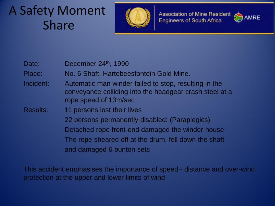
A Safety Moment Share
Date: December 24th, 1990 Place: No. 6 Shaft, Hartebeesfontein Gold Mine. Incident: Automatic man winder failed to stop, resulting in the conveyance colliding into the headgear crash steel at a rope speed of 13m/sec Results: 11 persons lost their lives 22 persons permanently disabled: (Paraplegics) Detached rope front-end damaged the winder house The rope sheared off at the drum, fell down the shaft and damaged 6 bunton sets This accident emphasises the importance of speed - distance and over-wind protection at the upper and lower limits of wind
Definition: Winder Dynamic testing
The execution of specific procedures to test the safety features of a winder during actual operating conditions
without compromising the safety of personnel or exposing machinery and equipment to damage
Typical Winder Dynamic tests
1. Winder Safety Circuit Interlocks 2. Speed - distance protection at the upper and lower limits of
the wind and in mid-shaft 3. Brake deceleration tests 4. Degree of Protection tests 5. Slack & Tight Rope tests
Safety Circuit tests
The safety circuit of a winder has a range of interlocks that must be tested, e.g. motor ventilation fan stopped, bearing oil flow failure, brake oil pump failure, etc. These interlocks will open the safety circuit, which in turn will remove power from the winder motor and apply the winder brakes Winder safety circuits are designed specifically for the type of winder, e.g. double drum, single drum, BMR, Koepe, Type of drive (AC or DC, Liquid controlled, Thyristor, Ward Leonard, etc.) The safety circuit trips are divided into three categories 1. Safety Circuit Trip: The power is removed from the winder and the brakes applied immediately. This is the most common safety circuit trip that occurs, like over-wind protection. 2. Lock-out trip: The circuit is initiated when a fault occurs but the winder is allowed to complete the trip, and the safety circuit will trip as soon as the winder brakes are applied. A typical example of this application is if a fault occurs on a winder’s ESCORT brakes control 3. Enforced creep: The circuit is initiated but the safety circuit doesn’t trip. The winder speed is enforced to creep speed (0.5m/sec) This type of condition is usually initiated by winder position synchronizing faults. (encoder failure, etc.)
Speed - Distance Protection
The speed - distance protection of a winder is designed to follow the speed curve of the winder throughout the length of wind at the licensed speed + 15%. It is standard practice for the alarm to sound at 10% over-speed and the safety circuit to trip the winder at 15% over-speed Each conveyance has it’s own individual speed-distance protection facilities / mine winder controller. (Lilly, MWC, Electronic Speed Distance Protection System) The Speed Distance protection for each conveyance must be tested in both directions of the wind
Over-wind protection
Each conveyance (Skip, cage or counterweight) in the shaft is protected with multiple over-wind protection devices: Controller over-wind protection (Lilly, AEI, Blacks, EMU) is a cam or encoder actuated over-wind device, either mounted on the mine winder controller or on an auxiliary drive Mechanical over-wind protection is an independent cam actuated or magnetic over-wind facility, normally driven from a second source. Ultimate Over-wind protection is a final over-wind trip facility at the upper limits of the wind, below the shaft crash steel and conveyance detaching facilities. This trip is normally initiated by the conveyance operating a switch through a trip wire rigged across the compartment. All over-wind protection devices must be tested regularly according to the Minerals Act, and the maintenance staff must be familiar of the testing procedures. NOTE: Incorrect testing procedures lead to shaft accidents
Brake deceleration tests
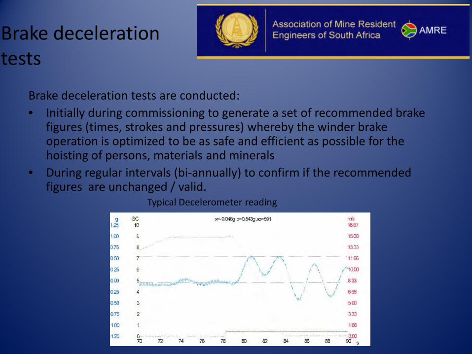
Brake deceleration tests are conducted: • Initially during commissioning to generate a set of recommended brake
figures (times, strokes and pressures) whereby the winder brake operation is optimized to be as safe and efficient as possible for the hoisting of persons, materials and minerals
• During regular intervals (bi-annually) to confirm if the recommended figures are unchanged / valid.
Typical Decelerometer reading
Degree of Protection
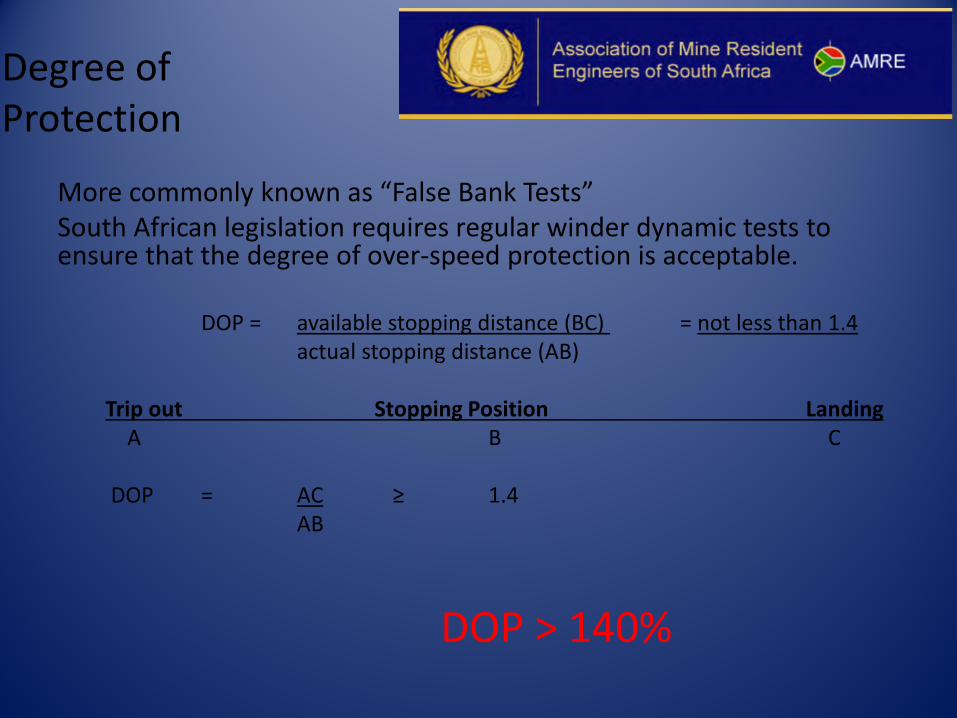
More commonly known as “False Bank Tests” South African legislation requires regular winder dynamic tests to ensure that the degree of over-speed protection is acceptable.
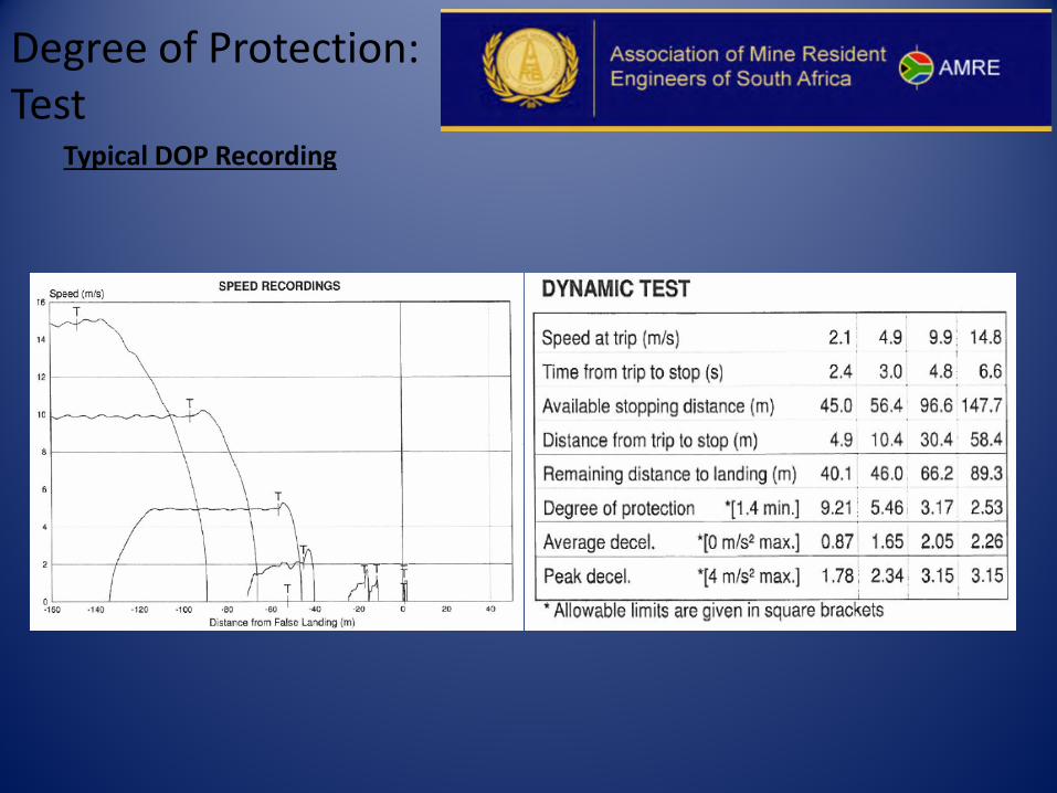
DOP = available stopping distance (BC) = not less than 1.4 actual stopping distance (AB) Trip out Stopping Position Landing A B C DOP = AC ≥ 1.4 AB
DOP > 140%
Degree of Protection: Critical Factors
Ensure that speed distance protection is correct
Ensure that brake settings are correct
Degree of Protection: Winder Brakes
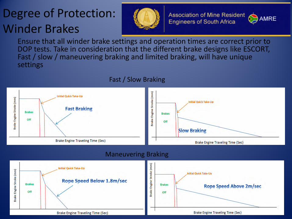
Ensure that all winder brake settings and operation times are correct prior to DOP tests. Take in consideration that the different brake designs like ESCORT, Fast / slow / maneuvering braking and limited braking, will have unique settings
Maneuvering Braking
Fast / Slow Braking
Degree of Protection: Winder Brakes
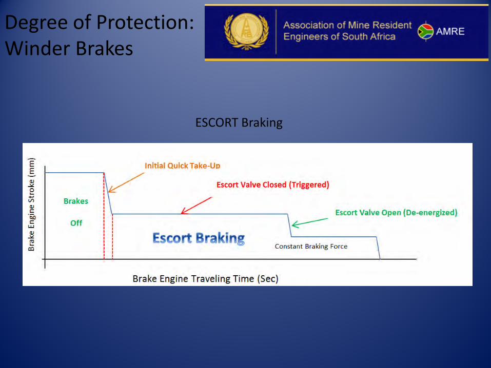
ESCORT Braking
Degree of Protection: Winder Brakes
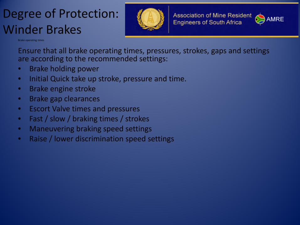
Brake operating times
Ensure that all brake operating times, pressures, strokes, gaps and settings are according to the recommended settings: • Brake holding power • Initial Quick take up stroke, pressure and time. • Brake engine stroke • Brake gap clearances • Escort Valve times and pressures • Fast / slow / braking times / strokes • Maneuvering braking speed settings • Raise / lower discrimination speed settings
Degree of Protection: Preparation
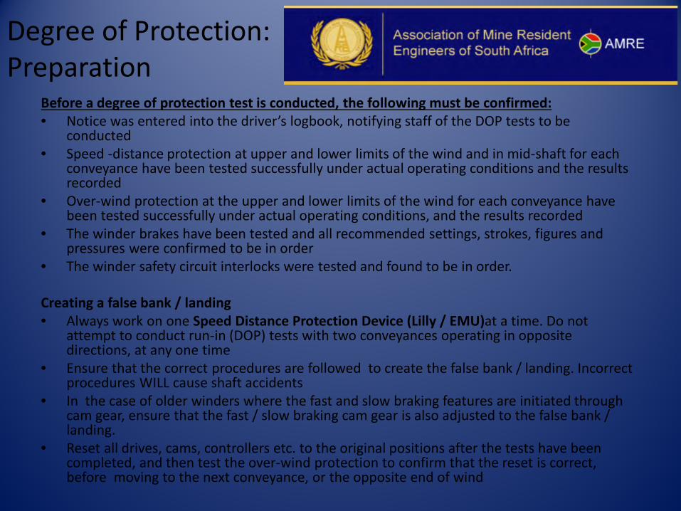
Before a degree of protection test is conducted, the following must be confirmed: • Notice was entered into the driver’s logbook, notifying staff of the DOP tests to be
conducted • Speed -distance protection at upper and lower limits of the wind and in mid-shaft for each
conveyance have been tested successfully under actual operating conditions and the results recorded
• Over-wind protection at the upper and lower limits of the wind for each conveyance have been tested successfully under actual operating conditions, and the results recorded
• The winder brakes have been tested and all recommended settings, strokes, figures and pressures were confirmed to be in order
• The winder safety circuit interlocks were tested and found to be in order.
Creating a false bank / landing • Always work on one Speed Distance Protection Device (Lilly / EMU)at a time. Do not
attempt to conduct run-in (DOP) tests with two conveyances operating in opposite directions, at any one time
• Ensure that the correct procedures are followed to create the false bank / landing. Incorrect procedures WILL cause shaft accidents
• In the case of older winders where the fast and slow braking features are initiated through cam gear, ensure that the fast / slow braking cam gear is also adjusted to the false bank / landing.
• Reset all drives, cams, controllers etc. to the original positions after the tests have been completed, and then test the over-wind protection to confirm that the reset is correct, before moving to the next conveyance, or the opposite end of wind
Degree of Protection: Test
Typical DOP Recording
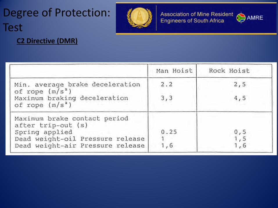
Degree of Protection: Test
C2 Directive (DMR)
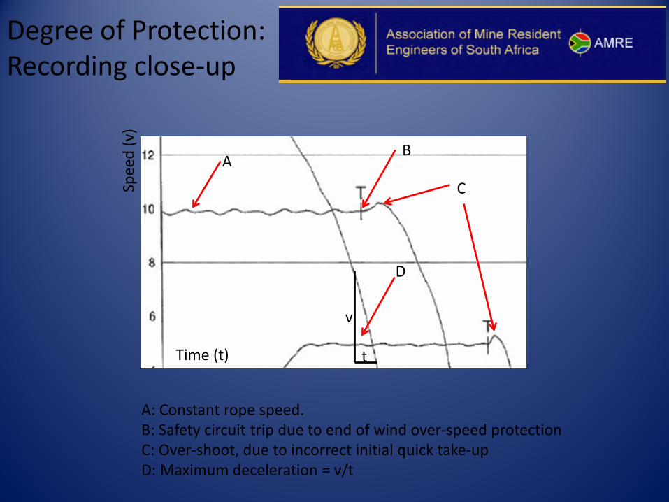
Degree of Protection: Recording close-up
A: Constant rope speed. B: Safety circuit trip due to end of wind over-speed protection C: Over-shoot, due to incorrect initial quick take-up D: Maximum deceleration = v/t
A
C
B
Time (t)
Spee
d (v
)
v
t
D
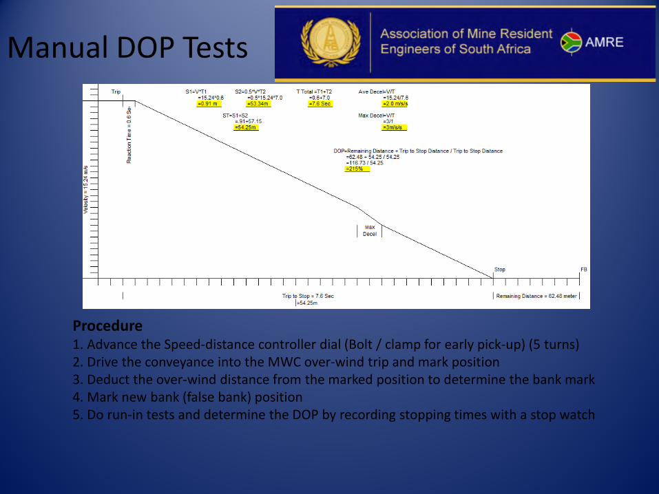
Manual DOP Tests
Procedure 1. Advance the Speed-distance controller dial (Bolt / clamp for early pick-up) (5 turns) 2. Drive the conveyance into the MWC over-wind trip and mark position 3. Deduct the over-wind distance from the marked position to determine the bank mark 4. Mark new bank (false bank) position 5. Do run-in tests and determine the DOP by recording stopping times with a stop watch

In a nut shell
Questions