Embed Size (px)
Citation preview
Engenharia Naval e Oceânica
COPPE/UFRJ & EP/UFRJ
2013 CAE NAVAL & OFFSHORE
Windsor Guanabara, Rio de Janeiro/RJ – Brasil
13 de Junho de 2013
SIMULATION OF FLOW AROUND FLOATING
STRUCTURES: SHIPS AND PLATFORMS
Alexandre T. P. Alho
Laboratório de Sistemas de Propulsão
DENO/POLI, UFRJ
Engenharia Naval e Oceânica
COPPE/UFRJ & EP/UFRJ 2013 CAE NAVAL & OFFSHORE – Windsor Guanabara, Rio de Janeiro/RJ – Brasil
INTRODUCTION
Preliminary Considerations
▪ Growing demand for high efficiency systems
▪ Demand for accurate predictions in less time and at low costs.
Accurate CFD models: designers can rely on as an effective
design tool.
CFD model must be developed based on a good compromise
between the quality of the numerical result and the computational
effort.
▪ Performance prediction of ships and offshore platforms
Experimental methods are well-established, but are usually
expensive and time-consuming.
Optimization process is virtually impossible based on experimental
methods: very high costs.

Engenharia Naval e Oceânica
COPPE/UFRJ & EP/UFRJ 2013 CAE NAVAL & OFFSHORE – Windsor Guanabara, Rio de Janeiro/RJ – Brasil
INTRODUCTION
Examples of CFD Projects
▪ CFD Predictions of the Hull Resistance and the Wave System of a
Catamaran.
▪ Investigate the performance of passive damping foils on heave
response of a catamaran.
▪ Develop a CFD model to study the effectiveness of passive damping
devices on heave motions of mono-column platforms.
Methodology
▪ The flow around vessel/platform hulls was simulated by means of
commercial CFD code (ANSYS CFX).
▪ Results are validated against experimental data (if available).

Engenharia Naval e Oceânica
COPPE/UFRJ & EP/UFRJ 2013 CAE NAVAL & OFFSHORE – Windsor Guanabara, Rio de Janeiro/RJ – Brasil
CFD PROJECTS – Resistance & Wave Cut
Motivation
▪ Growing demand for high speed multihull vessels.
Catamaran/SWATH concept has been received special attention
good performance in terms of speed and transversal stability.
Objective
▪ Validate a CFD model in terms of its performance on estimating hull
resistance and calculating the wave cuts generated by the hull.
Main Particulars
▪ Length (BP): 27.6 m
▪ Beam (each hull): 2.97 m
▪ Draft (design load): 1.5 m
▪ Block coefficient: 0.653

Engenharia Naval e Oceânica
COPPE/UFRJ & EP/UFRJ 2013 CAE NAVAL & OFFSHORE – Windsor Guanabara, Rio de Janeiro/RJ – Brasil
CFD PROJECTS – Resistance & Wave Cut
Main Particulars
▪ Length (BP): 27.6 m
▪ Beam (each hull): 2.97 m
▪ Draft (design load): 1.5 m
▪ Block coefficient: 0.653
Demihull separation
▪ 2.75 m (22), 5.25 m (42)
and 7.75 m (62):
0.9..2.6 B.
Significant interference effects
-0,15
-0,05
0,05
0,15
0,25
0,35
0,45
0,55
0,1 0,2 0,3 0,4 0,5 0,6
IF
Fn
IF. Sep 22
IF. Sep.42
IF. Sep.62

Engenharia Naval e Oceânica
COPPE/UFRJ & EP/UFRJ 2013 CAE NAVAL & OFFSHORE – Windsor Guanabara, Rio de Janeiro/RJ – Brasil
CFD PROJECTS – Resistance & Wave Cut
Hull Resistance
▪ In most cases, numerical errors are lower than 5.0% (max. 7.2%).
0
1000
2000
3000
4000
5000
6000
7000
8000
9000
0,25 0,3 0,35 0,4 0,45
Re
sis
tan
ce
(g
f)
Fn
Exp.
CFDHump & hollow
behavior well
described.
Unable to resolve
wave-breaking.

Engenharia Naval e Oceânica
COPPE/UFRJ & EP/UFRJ 2013 CAE NAVAL & OFFSHORE – Windsor Guanabara, Rio de Janeiro/RJ – Brasil
CFD PROJECTS – Resistance & Wave Cut
Free surface elevations
Good correlation upstream
and along the hull.
-0,03
-0,02
-0,01
0
0,01
0,02
0,03
-1 -0,5 0 0,5 1 1,5 2 2,5 3 3,5
Wave E
levati
on
x-position
Exp.
CFD
-0,04
-0,03
-0,02
-0,01
0
0,01
0,02
0,03
-1 -0,5 0 0,5 1 1,5 2 2,5 3 3,5
Wave E
levati
on
x-position
Exp.
CFD
-0,04
-0,03
-0,02
-0,01
0
0,01
0,02
0,03
0,04
-1 -0,5 0 0,5 1 1,5 2 2,5 3 3,5
Wave E
levati
on
x-position
Exp.
CFD
FN = 0.389
FN = 0.430
FN = 0.332

Engenharia Naval e Oceânica
COPPE/UFRJ & EP/UFRJ 2013 CAE NAVAL & OFFSHORE – Windsor Guanabara, Rio de Janeiro/RJ – Brasil
CFD PROJECTS – Heave Response
Objective
▪ Investigate the performance of passive damping foils on heave
response of a catamaran viscous damping coefficient.
Main Particulars
▪ Length (BP): 27.6 m
▪ Beam (each hull): 2.97 m
▪ Draft (design load): 1.5 m
▪ Block coefficient: 0.653
Passive damping foil.

Engenharia Naval e Oceânica
COPPE/UFRJ & EP/UFRJ 2013 CAE NAVAL & OFFSHORE – Windsor Guanabara, Rio de Janeiro/RJ – Brasil
CFD PROJECTS – Heave Response
Heave Response
Without Damping Foil With Damping Foil

Engenharia Naval e Oceânica
COPPE/UFRJ & EP/UFRJ 2013 CAE NAVAL & OFFSHORE – Windsor Guanabara, Rio de Janeiro/RJ – Brasil
CFD PROJECTS – Heave Response
Heave Response
Without Damping Foil With Damping Foil

Engenharia Naval e Oceânica
COPPE/UFRJ & EP/UFRJ 2013 CAE NAVAL & OFFSHORE – Windsor Guanabara, Rio de Janeiro/RJ – Brasil
CFD PROJECTS – Heave Response
Objective
▪ Develop a CFD model to study the effectiveness of passive damping
devices on heave motions of mono-column platforms.
Vertical Circular Cylinder
External dia.: 110 m
Moonpool dia.: 50 m
Central Moonpool
Devised to improve response
in waves.
External skirt: damping device

Engenharia Naval e Oceânica
COPPE/UFRJ & EP/UFRJ 2013 CAE NAVAL & OFFSHORE – Windsor Guanabara, Rio de Janeiro/RJ – Brasil
CFD PROJECTS – Heave Response
Free Decay Simulation: Original Skirt

Engenharia Naval e Oceânica
COPPE/UFRJ & EP/UFRJ 2013 CAE NAVAL & OFFSHORE – Windsor Guanabara, Rio de Janeiro/RJ – Brasil
CFD PROJECTS – Heave Response
Validation: Original Skirt
Time [s]
Ve
rtic
al d
isp
lace
me
nt
[Norm
.]
Decay period: good correlation!
Over-estimated amplitude: numerical
simulation did not include the damping
effect of mooring lines, risers, etc.
Numerical (CFD)
Experimental

Engenharia Naval e Oceânica
COPPE/UFRJ & EP/UFRJ 2013 CAE NAVAL & OFFSHORE – Windsor Guanabara, Rio de Janeiro/RJ – Brasil
Free Decay Simulation: Alternative Skirt Geometry
Alternative B
CFD PROJECTS – Heave Response

Engenharia Naval e Oceânica
COPPE/UFRJ & EP/UFRJ 2013 CAE NAVAL & OFFSHORE – Windsor Guanabara, Rio de Janeiro/RJ – Brasil
Objective
▪ Develop a CFD model dedicated to estimate the propulsion factors and
to simulate the self-propulsion test of a hull.
Focus
▪ Design applications.
Main Particulars:
▪ Length (Loa): 73.4 m
▪ Length (Lpp): 70.6 m
▪ Breath (B): 14.8 m
▪ Design draught (T): 2.6 m
▪ Service Speed (VS): 9.5 knt
CFD PROJECTS – Seft-propulsion Test
Engenharia Naval e Oceânica
COPPE/UFRJ & EP/UFRJ 2013 CAE NAVAL & OFFSHORE – Windsor Guanabara, Rio de Janeiro/RJ – Brasil
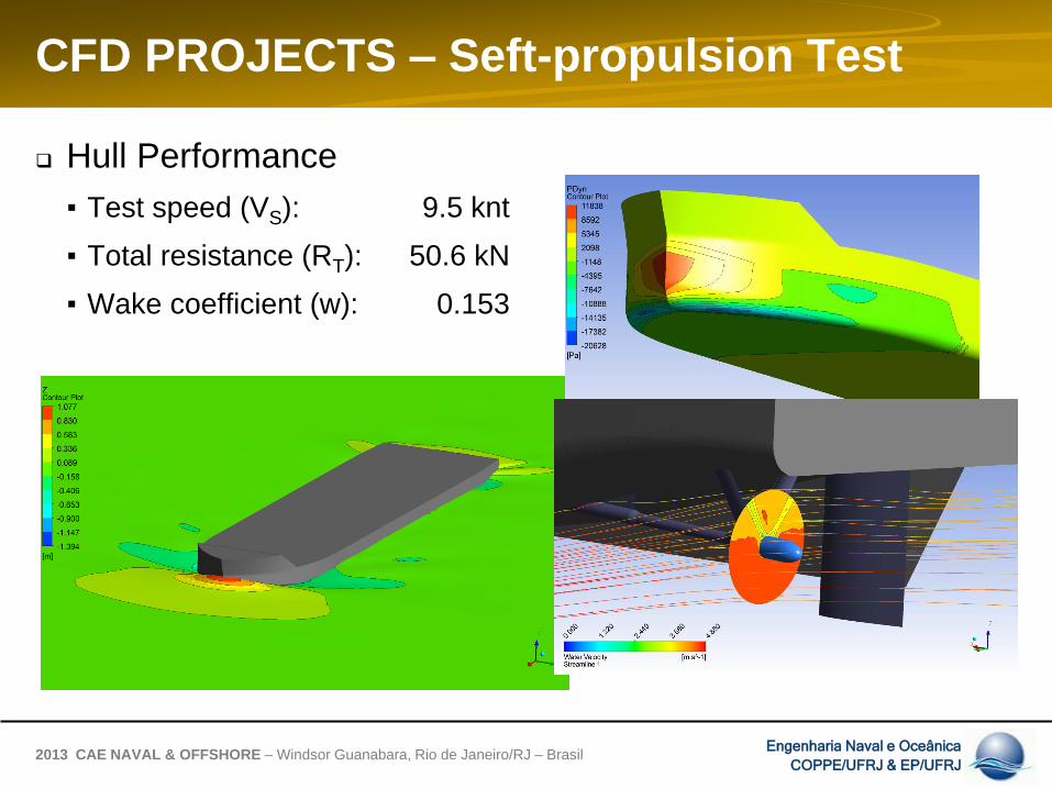
Hull Performance
▪ Test speed (VS): 9.5 knt
▪ Total resistance (RT): 50.6 kN
▪ Wake coefficient (w): 0.153
CFD PROJECTS – Seft-propulsion Test

Engenharia Naval e Oceânica
COPPE/UFRJ & EP/UFRJ 2013 CAE NAVAL & OFFSHORE – Windsor Guanabara, Rio de Janeiro/RJ – Brasil
Test Results
▪ Propeller revolutions (N): 433 rpm
▪ Propeller thrust (Treq): 65.3 kN
CFD PROJECTS – Seft-propulsion Test
N = 420 rpm

Engenharia Naval e Oceânica
COPPE/UFRJ & EP/UFRJ 2013 CAE NAVAL & OFFSHORE – Windsor Guanabara, Rio de Janeiro/RJ – Brasil
Results Evaluation
▪ Comparison against statistical estimation.
▪ Wake fraction, thrust deduction fraction and relative-rotative efficiency
predictions based on Holtrop & Mennen (1984).
CFD PROJECTS – Seft-propulsion Test
Statistical Numerical Dif.
Propeller Revolutions 456 433 -5.2% rpm
Propeller Thrust 70.4 65.3 -7.8% kN
Wake Fraction 0.181 0.153 -16.7% ---
Thrust Deduction Fraction 0.243 0.184 -32.3% ---
Relative-rotative Efficiency 1.028 1.024 -0.4% ---
Engenharia Naval e Oceânica
COPPE/UFRJ & EP/UFRJ 2013 CAE NAVAL & OFFSHORE – Windsor Guanabara, Rio de Janeiro/RJ – Brasil
The overall performance achieved suggests that the CFD
numerical models were able to resolve the physics of the
flow around vessel/platform hulls.
The comparison against experimental results showed that
the numerical models were able to provide reasonable
performance predictions, suggesting that designers can rely
on CFD models as an effective design tool.
FINAL REMARKS

![A STUDY ON THE STATISTICAL CALIBRATION OF THE HOLTROP … · 31 The Holtrop and Mennen method [3], [4] is currently considered as one of the most accurate and efficient methods for](https://img.pdfslide.net/doc/110x75/5e0ab1a6f9629346bb437583/a-study-on-the-statistical-calibration-of-the-holtrop-31-the-holtrop-and-mennen.jpg)


![Comparative Study of Ship Resistance between Model Test ... · In their approach to establishing their formulas, Holtrop and Mennen [2,3] assumed that the non-dimensional coefficient](https://img.pdfslide.net/doc/110x75/5e0ab38e13ae20423d428ead/comparative-study-of-ship-resistance-between-model-test-in-their-approach-to.jpg)
![ANALIYSIS OF PROPULSION FOR VARIOUS TYPES OF … · systematic model research. Holtrop –Mennen method represents such kind of calculation [1,8]. 2. Characteristic of elements of](https://img.pdfslide.net/doc/110x75/5afaaba67f8b9a2d5d8e917f/analiysis-of-propulsion-for-various-types-of-model-research-holtrop-mennen.jpg)


![Simulation of the Operation of Wind-Assisted Cargo Ships · rechnungsverfahren von Holtrop-Mennen [4] be-rechnet, der Seegangswiderstand nach Kreitner (in [10]), der Windwiderstand](https://img.pdfslide.net/doc/110x75/5e102d326a968c52157c2af1/simulation-of-the-operation-of-wind-assisted-cargo-rechnungsverfahren-von-holtrop-mennen.jpg)