Embed Size (px)
Citation preview
WinKey USB SMT Assembly and Operation Guide - Version 1.5 12/26/2017 Pg 1
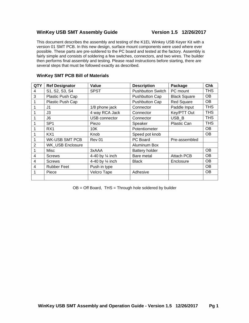
WinKey USB SMT Assembly Guide Version 1.5 12/26/2017 This document describes the assembly and testing of the K1EL Winkey USB Keyer Kit with a version 01 SMT PCB. In this new design, surface mount components were used where ever possible. These parts are pre-soldered to the PC board and tested at the factory. Assembly is fairly simple and consists of soldering a few switches, connectors, and two wires. The builder then performs final assembly and testing. Please read instructions before starting, there are several steps that must be followed exactly as described. WinKey SMT PCB Bill of Materials
QTY Ref Designator Value Description Package Chk 4 S1, S2, S3, S4 SPST Pushbutton Switch PC mount THS 3 Plastic Push Cap Pushbutton Cap Black Square OB 1 Plastic Push Cap Pushbutton Cap Red Square OB 1 J1 1/8 phone jack Connector Paddle Input THS 1 J3 4 way RCA Jack Connector Key/PTT Out THS 1 J6 USB connector Connector USB_B THS 1 SP1 Piezo Speaker Plastic Can THS 1 RX1 10K Potentiometer OB 1 KX1 Knob Speed pot knob OB 1 WK-USB SMT PCB Rev 01 PC Board Pre-assembled 2 WK_USB Enclosure Aluminum Box 1 Misc 3xAAA Battery holder OB 4 Screws 4-40 by ¼ inch Bare metal Attach PCB OB 4 Screws 4-40 by ¼ inch Black Enclosure OB 4 Rubber Feet Push in type OB 1 Piece Velcro Tape Adhesive OB
OB = Off Board, THS = Through hole soldered by builder
WinKey USB SMT Assembly and Operation Guide - Version 1.5 12/26/2017 Pg 2
Kit Assembly
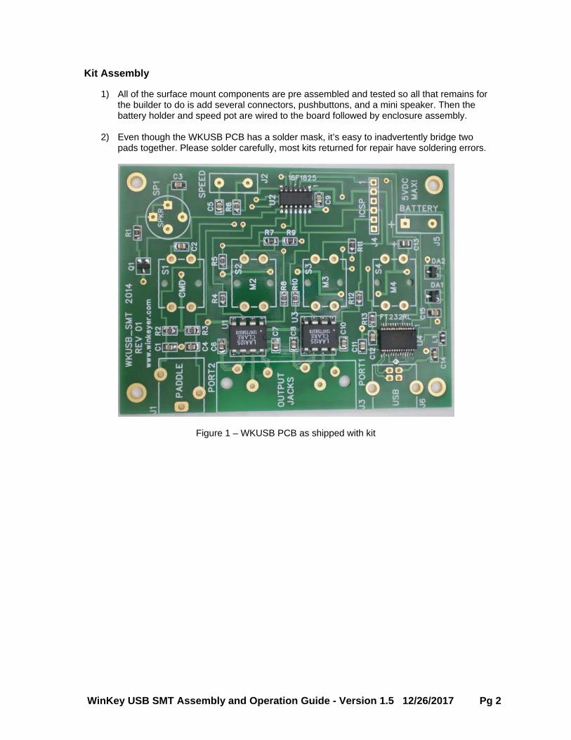
1) All of the surface mount components are pre assembled and tested so all that remains for the builder to do is add several connectors, pushbuttons, and a mini speaker. Then the battery holder and speed pot are wired to the board followed by enclosure assembly.
2) Even though the WKUSB PCB has a solder mask, it’s easy to inadvertently bridge two pads together. Please solder carefully, most kits returned for repair have soldering errors.
Figure 1 – WKUSB PCB as shipped with kit
WinKey USB SMT Assembly and Operation Guide - Version 1.5 12/26/2017 Pg 3
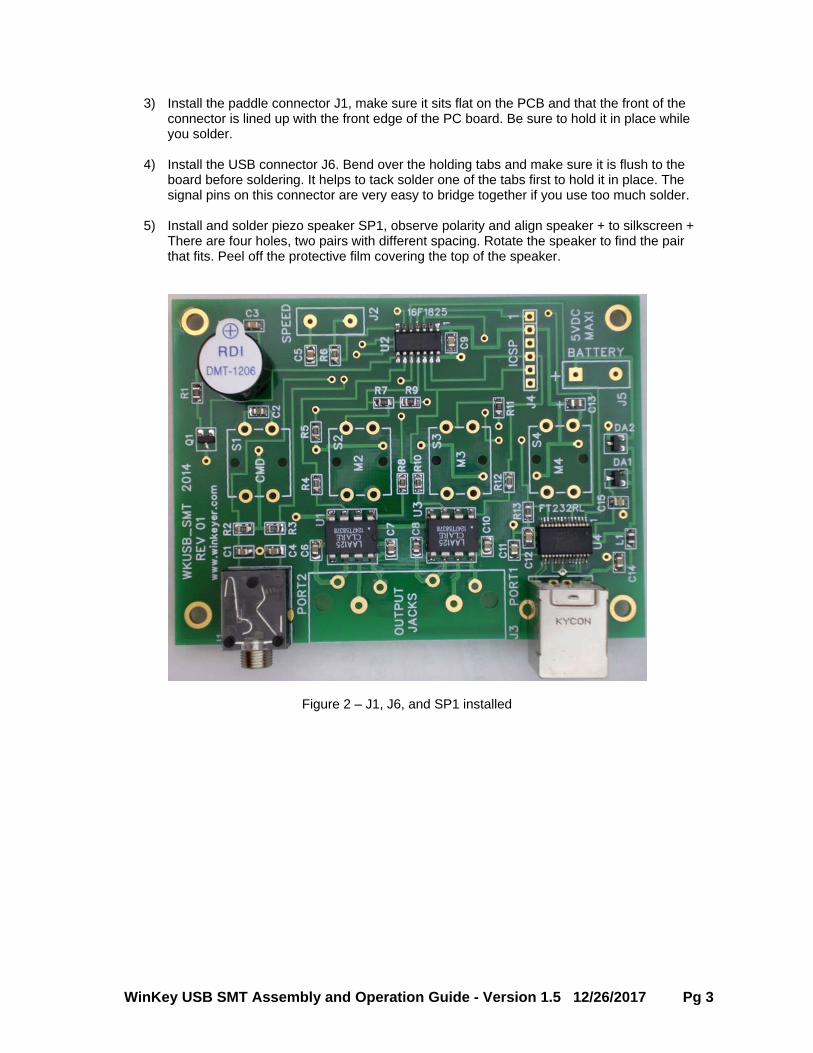
3) Install the paddle connector J1, make sure it sits flat on the PCB and that the front of the connector is lined up with the front edge of the PC board. Be sure to hold it in place while you solder.
4) Install the USB connector J6. Bend over the holding tabs and make sure it is flush to the board before soldering. It helps to tack solder one of the tabs first to hold it in place. The signal pins on this connector are very easy to bridge together if you use too much solder.
5) Install and solder piezo speaker SP1, observe polarity and align speaker + to silkscreen + There are four holes, two pairs with different spacing. Rotate the speaker to find the pair that fits. Peel off the protective film covering the top of the speaker.
Figure 2 – J1, J6, and SP1 installed
WinKey USB SMT Assembly and Operation Guide - Version 1.5 12/26/2017 Pg 4
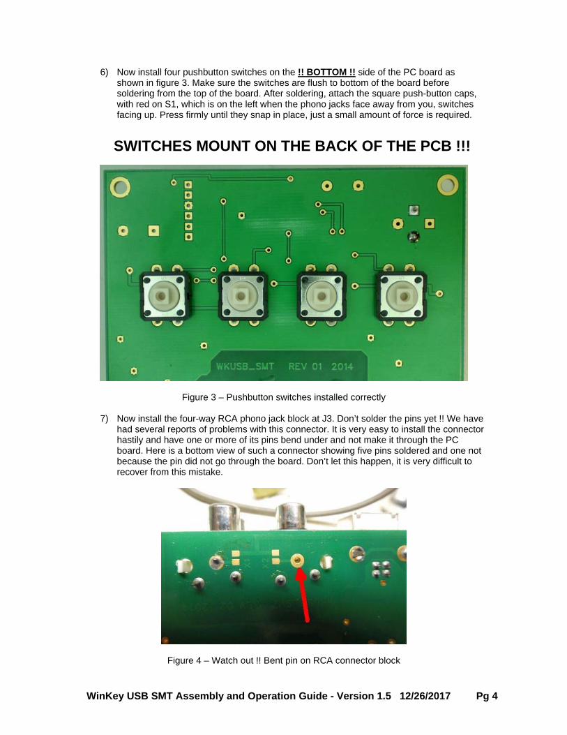
6) Now install four pushbutton switches on the !! BOTTOM !! side of the PC board as shown in figure 3. Make sure the switches are flush to bottom of the board before soldering from the top of the board. After soldering, attach the square push-button caps, with red on S1, which is on the left when the phono jacks face away from you, switches facing up. Press firmly until they snap in place, just a small amount of force is required.
SWITCHES MOUNT ON THE BACK OF THE PCB !!!
Figure 3 – Pushbutton switches installed correctly
7) Now install the four-way RCA phono jack block at J3. Don’t solder the pins yet !! We have had several reports of problems with this connector. It is very easy to install the connector hastily and have one or more of its pins bend under and not make it through the PC board. Here is a bottom view of such a connector showing five pins soldered and one not because the pin did not go through the board. Don’t let this happen, it is very difficult to recover from this mistake.
Figure 4 – Watch out !! Bent pin on RCA connector block
WinKey USB SMT Assembly and Operation Guide - Version 1.5 12/26/2017 Pg 5
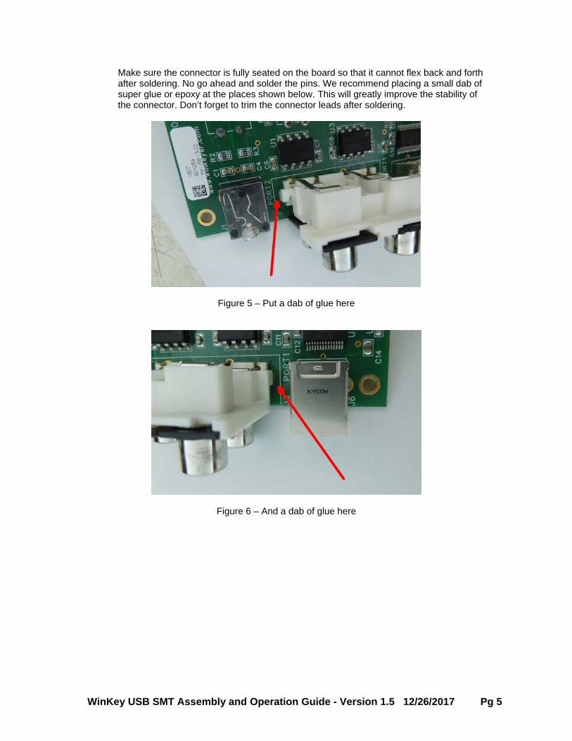
Make sure the connector is fully seated on the board so that it cannot flex back and forth after soldering. No go ahead and solder the pins. We recommend placing a small dab of super glue or epoxy at the places shown below. This will greatly improve the stability of the connector. Don’t forget to trim the connector leads after soldering.
Figure 5 – Put a dab of glue here
Figure 6 – And a dab of glue here
WinKey USB SMT Assembly and Operation Guide - Version 1.5 12/26/2017 Pg 6
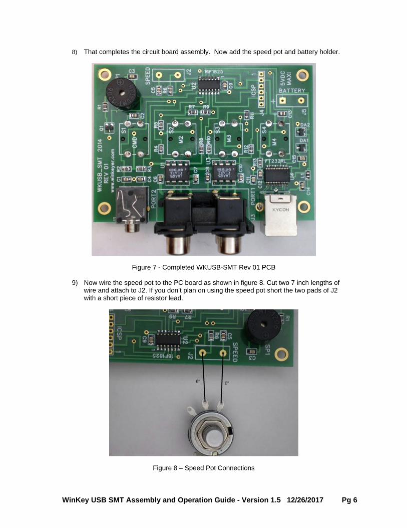
8) That completes the circuit board assembly. Now add the speed pot and battery holder.
Figure 7 - Completed WKUSB-SMT Rev 01 PCB
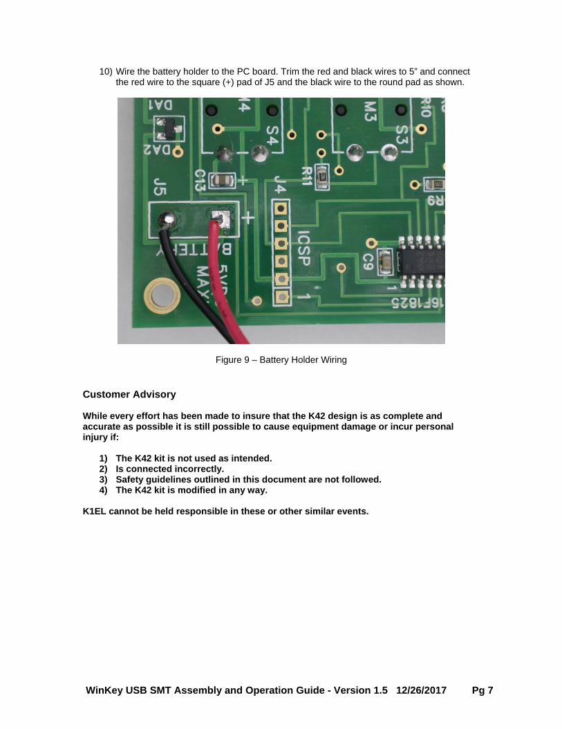
9) Now wire the speed pot to the PC board as shown in figure 8. Cut two 7 inch lengths of wire and attach to J2. If you don’t plan on using the speed pot short the two pads of J2 with a short piece of resistor lead.
Figure 8 – Speed Pot Connections
WinKey USB SMT Assembly and Operation Guide - Version 1.5 12/26/2017 Pg 7
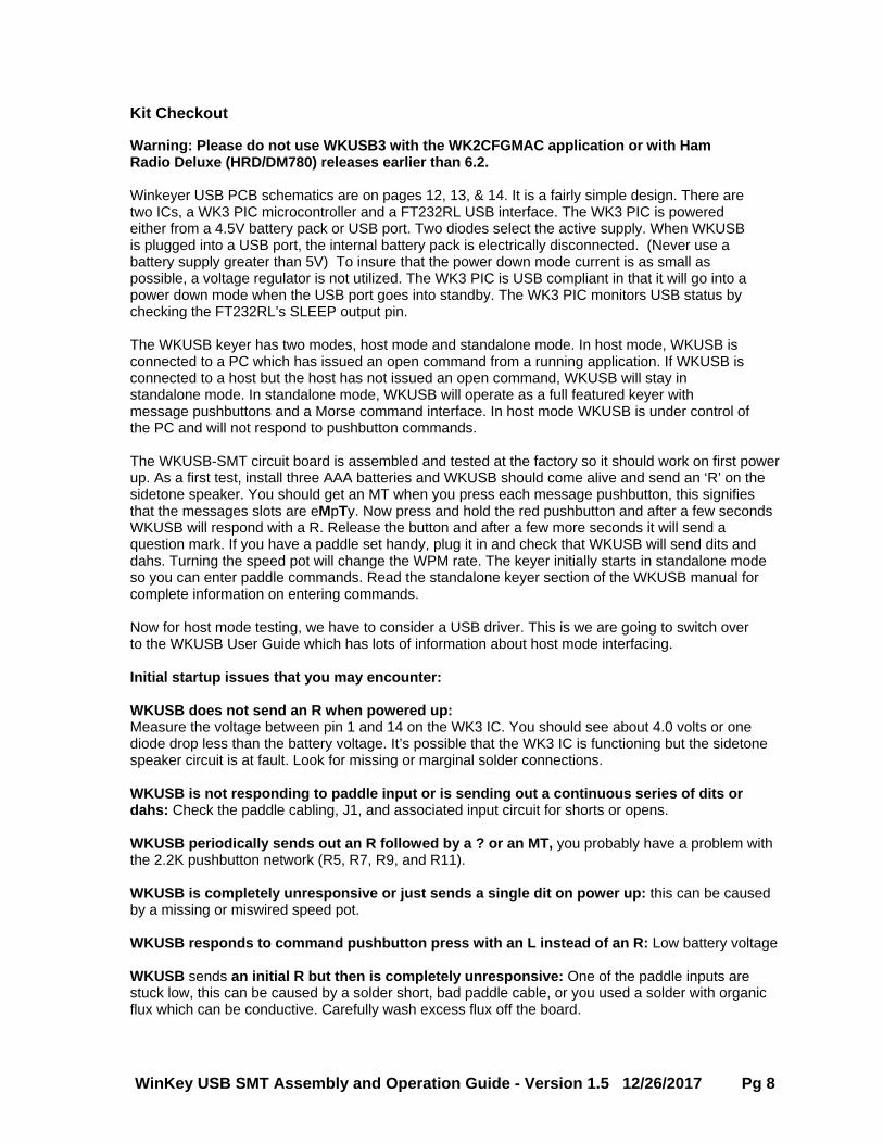
10) Wire the battery holder to the PC board. Trim the red and black wires to 5” and connect the red wire to the square (+) pad of J5 and the black wire to the round pad as shown.
Figure 9 – Battery Holder Wiring Customer Advisory While every effort has been made to insure that the K42 design is as complete and accurate as possible it is still possible to cause equipment damage or incur personal injury if:
1) The K42 kit is not used as intended. 2) Is connected incorrectly. 3) Safety guidelines outlined in this document are not followed. 4) The K42 kit is modified in any way.
K1EL cannot be held responsible in these or other similar events.
WinKey USB SMT Assembly and Operation Guide - Version 1.5 12/26/2017 Pg 8
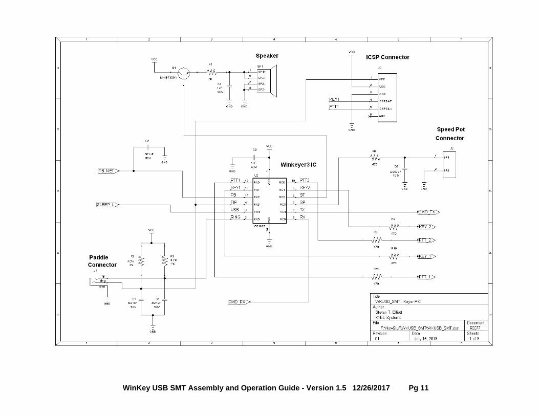
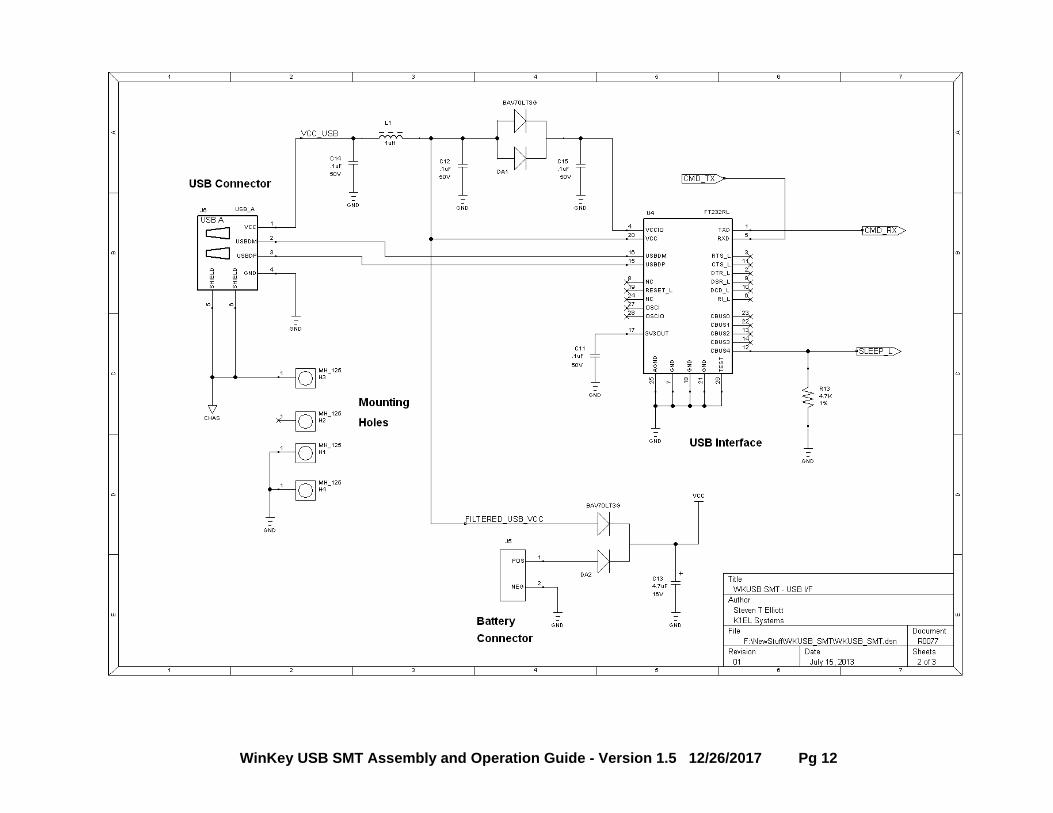
Kit Checkout Warning: Please do not use WKUSB3 with the WK2CFGMAC application or with Ham Radio Deluxe (HRD/DM780) releases earlier than 6.2. Winkeyer USB PCB schematics are on pages 12, 13, & 14. It is a fairly simple design. There are two ICs, a WK3 PIC microcontroller and a FT232RL USB interface. The WK3 PIC is powered either from a 4.5V battery pack or USB port. Two diodes select the active supply. When WKUSB is plugged into a USB port, the internal battery pack is electrically disconnected. (Never use a battery supply greater than 5V) To insure that the power down mode current is as small as possible, a voltage regulator is not utilized. The WK3 PIC is USB compliant in that it will go into a power down mode when the USB port goes into standby. The WK3 PIC monitors USB status by checking the FT232RL’s SLEEP output pin. The WKUSB keyer has two modes, host mode and standalone mode. In host mode, WKUSB is connected to a PC which has issued an open command from a running application. If WKUSB is connected to a host but the host has not issued an open command, WKUSB will stay in standalone mode. In standalone mode, WKUSB will operate as a full featured keyer with message pushbuttons and a Morse command interface. In host mode WKUSB is under control of the PC and will not respond to pushbutton commands. The WKUSB-SMT circuit board is assembled and tested at the factory so it should work on first power up. As a first test, install three AAA batteries and WKUSB should come alive and send an ‘R’ on the sidetone speaker. You should get an MT when you press each message pushbutton, this signifies that the messages slots are eMpTy. Now press and hold the red pushbutton and after a few seconds WKUSB will respond with a R. Release the button and after a few more seconds it will send a question mark. If you have a paddle set handy, plug it in and check that WKUSB will send dits and dahs. Turning the speed pot will change the WPM rate. The keyer initially starts in standalone mode so you can enter paddle commands. Read the standalone keyer section of the WKUSB manual for complete information on entering commands. Now for host mode testing, we have to consider a USB driver. This is we are going to switch over to the WKUSB User Guide which has lots of information about host mode interfacing.
Initial startup issues that you may encounter: WKUSB does not send an R when powered up: Measure the voltage between pin 1 and 14 on the WK3 IC. You should see about 4.0 volts or one diode drop less than the battery voltage. It’s possible that the WK3 IC is functioning but the sidetone speaker circuit is at fault. Look for missing or marginal solder connections. WKUSB is not responding to paddle input or is sending out a continuous series of dits or dahs: Check the paddle cabling, J1, and associated input circuit for shorts or opens. WKUSB periodically sends out an R followed by a ? or an MT, you probably have a problem with the 2.2K pushbutton network (R5, R7, R9, and R11). WKUSB is completely unresponsive or just sends a single dit on power up: this can be caused by a missing or miswired speed pot. WKUSB responds to command pushbutton press with an L instead of an R: Low battery voltage WKUSB sends an initial R but then is completely unresponsive: One of the paddle inputs are stuck low, this can be caused by a solder short, bad paddle cable, or you used a solder with organic flux which can be conductive. Carefully wash excess flux off the board.
WinKey USB SMT Assembly and Operation Guide - Version 1.5 12/26/2017 Pg 9
Here are instructions for installing the WKUSB-SMT assembly into the enclosure.
1) Using spray cleaner and paper towels, clean the inside surfaces of the top and base enclosure halves to remove any dirt, grease, or metal filings.
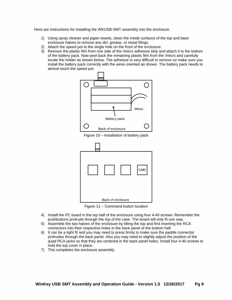
2) Attach the speed pot to the single hole on the front of the enclosure. 3) Remove the plastic film from one side of the Velcro adhesive strip and attach it to the bottom
of the battery pack. Now peel back the remaining plastic film from the Velcro and carefully locate the holder as shown below. The adhesive is very difficult to remove so make sure you install the battery pack correctly with the wires oriented as shown. The battery pack needs to almost touch the speed pot.
Battery pack
Back of enclosure
Wires
Figure 10 – Installation of battery pack
Back of enclosure
CMD
Figure 11 – Command button location
4) Install the PC board in the top half of the enclosure using four 4-40 screws. Remember the
pushbuttons protrude through the top of the case. The board will only fit one way. 5) Assemble the two halves of the enclosure by tilting the top and first inserting the RCA
connectors into their respective holes in the back panel of the bottom half. 6) It can be a tight fit and you may need to press firmly to make sure the paddle connector
protrudes through the back panel. Also you may need to slightly adjust the position of the quad RCA jacks so that they are centered in the back panel holes. Install four 4-40 screws to hold the top cover in place.
7) This completes the enclosure assembly.
WinKey USB SMT Assembly and Operation Guide - Version 1.5 12/26/2017 Pg 10
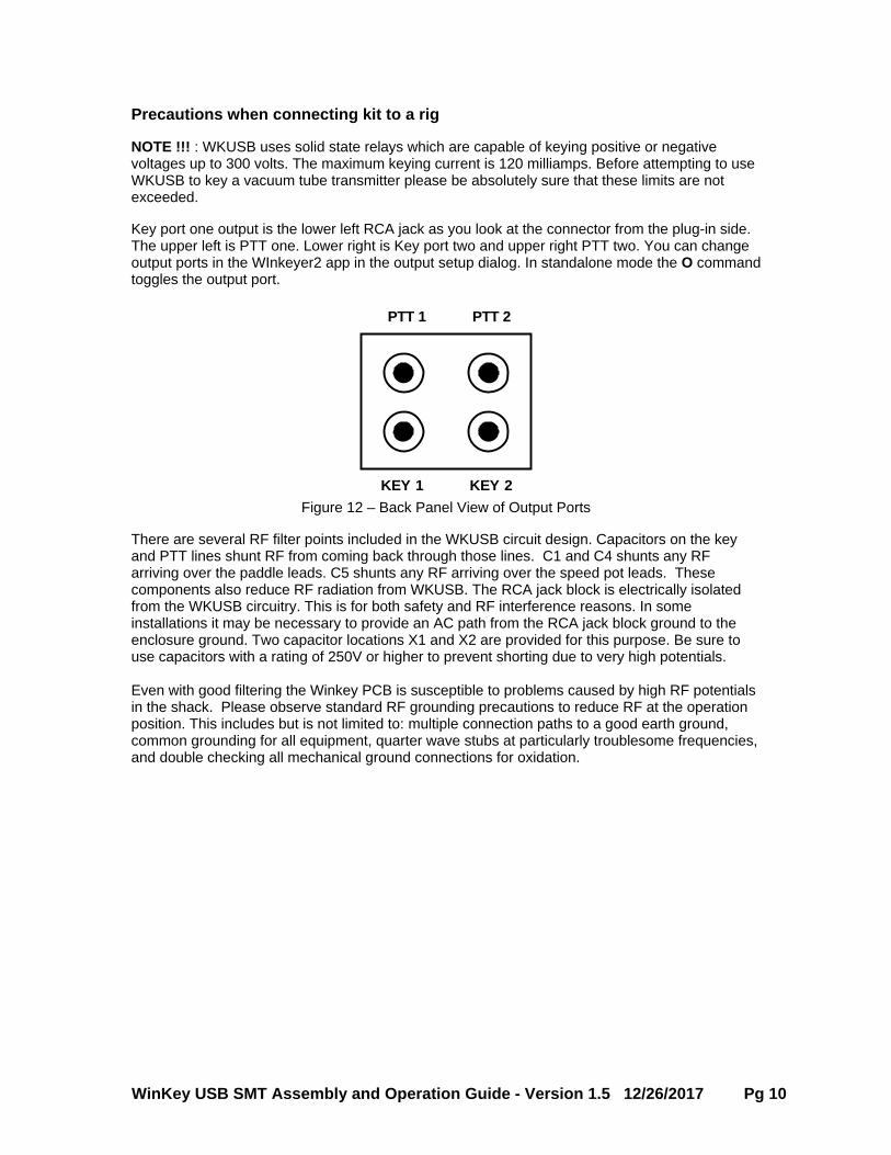
Precautions when connecting kit to a rig NOTE !!! : WKUSB uses solid state relays which are capable of keying positive or negative voltages up to 300 volts. The maximum keying current is 120 milliamps. Before attempting to use WKUSB to key a vacuum tube transmitter please be absolutely sure that these limits are not exceeded. Key port one output is the lower left RCA jack as you look at the connector from the plug-in side. The upper left is PTT one. Lower right is Key port two and upper right PTT two. You can change output ports in the WInkeyer2 app in the output setup dialog. In standalone mode the O command toggles the output port.
PTT 1 PTT 2
KEY 1 KEY 2 Figure 12 – Back Panel View of Output Ports
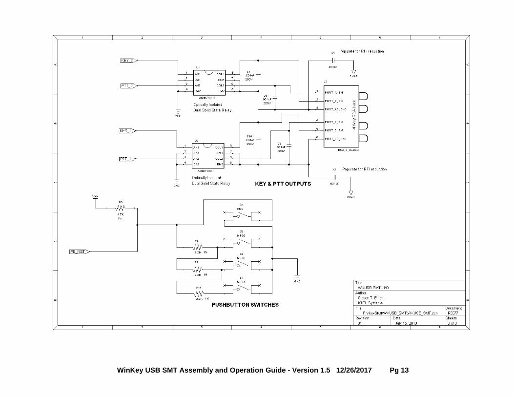
There are several RF filter points included in the WKUSB circuit design. Capacitors on the key and PTT lines shunt RF from coming back through those lines. C1 and C4 shunts any RF arriving over the paddle leads. C5 shunts any RF arriving over the speed pot leads. These components also reduce RF radiation from WKUSB. The RCA jack block is electrically isolated from the WKUSB circuitry. This is for both safety and RF interference reasons. In some installations it may be necessary to provide an AC path from the RCA jack block ground to the enclosure ground. Two capacitor locations X1 and X2 are provided for this purpose. Be sure to use capacitors with a rating of 250V or higher to prevent shorting due to very high potentials. Even with good filtering the Winkey PCB is susceptible to problems caused by high RF potentials in the shack. Please observe standard RF grounding precautions to reduce RF at the operation position. This includes but is not limited to: multiple connection paths to a good earth ground, common grounding for all equipment, quarter wave stubs at particularly troublesome frequencies, and double checking all mechanical ground connections for oxidation.
WinKey USB SMT Assembly and Operation Guide - Version 1.5 12/26/2017 Pg 11
WinKey USB SMT Assembly and Operation Guide - Version 1.5 12/26/2017 Pg 12
WinKey USB SMT Assembly and Operation Guide - Version 1.5 12/26/2017 Pg 13
WinKey USB SMT Assembly and Operation Guide - Version 1.5 12/26/2017 Pg 14
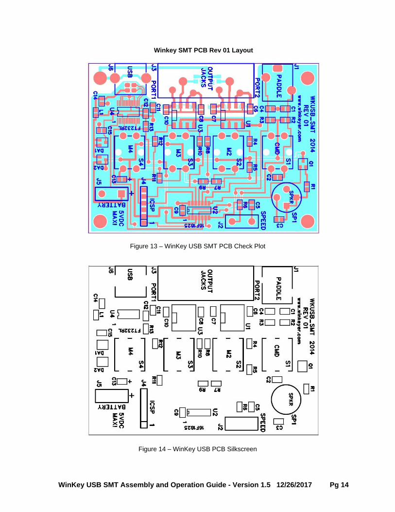
Winkey SMT PCB Rev 01 Layout
Figure 13 – WinKey USB SMT PCB Check Plot
Figure 14 – WinKey USB PCB Silkscreen
WinKey USB SMT Assembly and Operation Guide - Version 1.5 12/26/2017 Pg 15
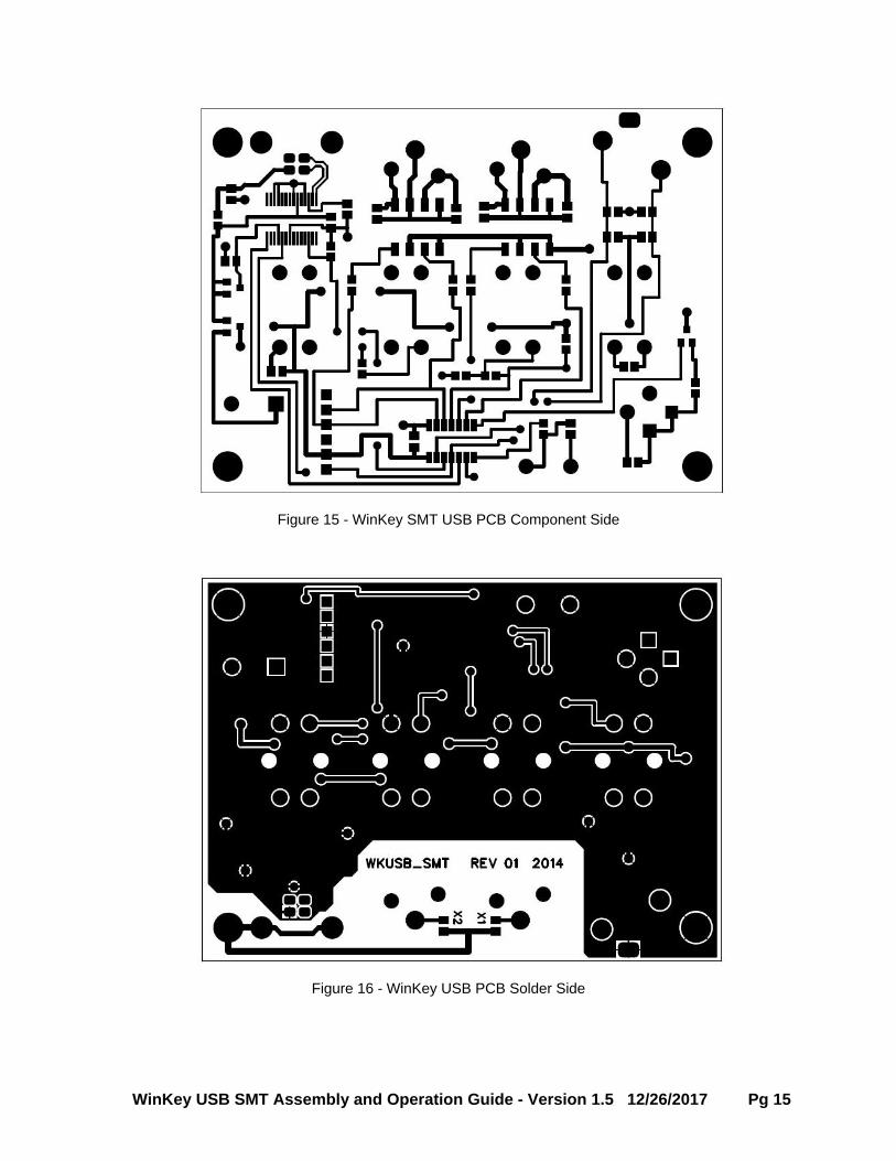
Figure 15 - WinKey SMT USB PCB Component Side
Figure 16 - WinKey USB PCB Solder Side
WinKey USB SMT Assembly and Operation Guide - Version 1.5 12/26/2017 Pg 16
Standalone Considerations Here’s a list of things to know about standalone operation. 1) When WKUSB is powered up for the first time it loads a default set of standalone
parameters. 2) These parameters can be modified through standalone paddle commands or by hooking
WKUSB up to the Windows application WK3MGR. This is on the CD in the WK3MGR directory.
3) If the user modifies parameters in standalone mode and wants to preserve them, they need to remember to save the settings with the standalone P command.
4) When WKUSB is connected to the USB port, the PC recognizes the USB device and registers it but WKUSB remains in standalone mode until an application opens it. The only serial commands WKUSB will accept while in standalone are ADMIN commands.
5) WK3MGR works by directly reading and writing the EEPROM in the WK3 IC. The EEPROM contains all of the standalone settings and local messages. Since the EEPROM is accessed by ADMIN commands, WKUSB can remain in a closed state.
6) When an application opens WKUSB, WKUSB leaves standalone mode and will no longer responds to the command pushbutton making it impossible to enter paddle commands.
7) After opening WKUSB the host application overwrites the standalone settings with settings dictated by the host. This must be done to insure settings listed in the host application’s dialog boxes are in sync with those in WKUSB.
8) You can not run WK3MGR when another application is connected to WKUSB. 9) When the host application closes WKUSB, standalone operation is restored and the
EEPROM settings are reloaded.
WinKey USB SMT Assembly and Operation Guide - Version 1.5 12/26/2017 Pg 17
Contents WinKey SMT PCB Bill of Materials .................................................................................................. 1 Kit Assembly .................................................................................................................................... 2
Figure 1 – WKUSB PCB as shipped with kit ................................................................................ 2 Figure 2 – J1, J6, and SP1 installed ............................................................................................ 3 Figure 3 – Pushbutton switches installed correctly ...................................................................... 4 Figure 4 – Watch out !! Bent pin on RCA connector block .......................................................... 4 Figure 5 – Put a dab of glue here ................................................................................................ 5 Figure 6 – And a dab of glue here ............................................................................................... 5 Figure 7 - Completed WKUSB-SMT Rev 01 PCB ....................................................................... 6 Figure 8 – Speed Pot Connections .............................................................................................. 6 Figure 9 – Battery Holder Wiring.................................................................................................. 7
Customer Advisory .......................................................................................................................... 7 Kit Checkout .................................................................................................................................... 8
Figure 10 – Installation of battery pack ........................................................................................ 9 Figure 11 – Command button location ......................................................................................... 9
Precautions when connecting kit to a rig ....................................................................................... 10 Figure 12 – Back Panel View of Output Ports ........................................................................... 10 Figure 13 – WinKey USB SMT PCB Check Plot ....................................................................... 14 Figure 14 – WinKey USB PCB Silkscreen ................................................................................. 14 Figure 15 - WinKey SMT USB PCB Component Side ............................................................... 15 Figure 16 - WinKey USB PCB Solder Side ................................................................................ 15
Standalone Considerations ........................................................................................................... 16