Embed Size (px)
Citation preview

WIRE ROPE USER MANUAL
ushamartin.com

USHA MARTIN GROUPUsha Martin is one of the largest manufacturers of high quality wire ropes in the world.For more than 50 years, the group has been dedicated to excellence and has implemented stringent process controls at each step of the manufacturing process.
In this world without boundaries, Usha Martin is truly committed to preserve this legacy of quality all
over the world and continues to harness it’s global presence to deliver the best possible solutions for
it’s customers.
The Usha Martin Group, with it’s own coal and iron ore mines, 150 MW power plant and over 1
million tons of speciality steel manufacturing capacity, is a truly vertically integrated business.
It has a global base of steel wire rope manufacturing facilities located in India, the UK, Thailand and
Dubai with service centres spread over all of the key markets in Europe, Asia, Americas and Africa.

01
This document is property of Usha Martin Italia. Reproduction is not allowed unless specifically agreed.
2
3
4
6
7
8
9
10
11
12
14
16
18
19
20
22
24
26
28
30
32
33
34
36
38
39
40
42
44
46
47
51
52
Preface about rope use .........................................................
Rope diameter and measurement ............................................
Rope lay measurement and selection........................................
Strength & breaking force......................................................
Material & surface finish........................................................
Benefits of compacted strands.................................................
Fleet angle and plastic impregnated core ropes............................
Rope behaviour under load.....................................................
Rotational characteristics......................................................
Block stability and use of swivel ..............................................
Wire rope lubrication............................................................
Reel receipt and storage........................................................
Serving and cutting..............................................................
Rope pay out......................................................................
Rope terminations...............................................................
Socketing operation.............................................................
Rope installation and training..................................................
Lifting operations................................................................
Rope winding over sheaves.....................................................
Contact pressure between rope and sheaves................................
Rope relubrication...............................................................
Bending fatigue..................................................................
Factors affecting bending fatigue.............................................
Guidelines for rope inspection.................................................
Inspection of grooves and sheaves............................................
Typical rope damages and recommended actions..........................
Discard criteria for visible broken wires.....................................
Discard criteria for diameter decrease, deformation and corrosion.. . .
Health and safety information.................................................
Appendix A Quick calculator................................................
Appendix B Definitions.......................................................
Appendix C Reference documents.........................................
Appendix D Examples of strands and ropes constructions.............
List of topics

This document is property of Usha Martin Italia. Reproduction is not allowed unless specifically agreed.
PREFACE ABOUT ROPE USEA wire rope can be simply considered as an
assembly of several strands laid helically in
different possible arrangements in order to
bear axial loads.
To be fit for purpose, it must also ensure other
features, like resistance to side loads, flexibility,
handling and stability.
This definition, however, does not cover
completely the implications of correct rope
design, manufacturing, use and inspection,
as the real mandatory requirement must be,
in any case, safety compliance, which allows
adequate working conditions for men and
environment.
To ensure high quality standards, our Company
has settled up a complete process, which includes
custom design software, state of the art
manufacturing equipment and skilled personnel
with proven expertise.
Rope integrity management should always be
operated by properly trained personnel, who
should always refer to general regulations,
specific customer standards, local legislation
and internal guidance.
The content of this document is a brief abstract
of rope characteristics and recommendations
for rope use and it is not intended to be
all-inclusive; specific matters can be followed
with special care to customer needs by our
technical departments.

03
This document is property of Usha Martin Italia. Reproduction is not allowed unless specifically agreed.
ROPE DIAMETER AND MEASUREMENT
Figure 1 Diameter measurement
Each rope is first of all characterized by the
nominal diameter and oversize, which have to
be selected depending on system configuration
and reference regulations.
According to EN12385-1, ISO and API standard,
diameter measurement has to be taken on a
straight portion of the rope, either under no
tension or a tension not exceeding 5% of the
minimum breaking force, at two positions spaced
at least one metre apart. At each position two
measurements, at right angles, of the
circumscribed circle diameter shall be taken.
The most suitable measuring equipment is plate
gauge, capable to cover at least two strands
(see Figure 1).
Figure 3 Core distortion and associated diameter increase
Figure 2 Sunken strand and associated diameter reduction
Diameter must be measured and recorded
immediately after rope receipt, as this value
has to be used as a baseline for following
inspections.
It has always to be considered that the actual
diameter of the rope changes during use due
to initial stabilization, to the effect of working
tension and to wear generated by the passage
over the reeving system.
Permanent diameter reduction after first pull
can vary from 0.5% to 3% depending on rope
and core construction.
Diameter measurement is an essential tool which
can give an immediate and simple evaluation of
the overall condition of the rope.
For example, a localized diameter variation can
indicate undesired phenomena like geometrical
deformation, core distortion or presence of
heavy corrosion, while a distributed diameter
reduction can be associated to wear due to
intensive use. Ovalization is also a marker of
possible rope issues which have to be properly
addressed.

This document is property of Usha Martin Italia. Reproduction is not allowed unless specifically agreed.
ROPE LAY MEASUREMENT AND SELECTION
Figure 4 Lay length measurement for a six strand rope
Figure 5 Lang lay (first figure) and regular lay (second figure)
The choice of a Lang or regular lay rope has to
be based on rope use and desired performance.
Lang lay ropes (i.e. ropes having same direction
as the outer strands) give better stability
to side wear (phenomenon also known as
“crushing”) as the contacts between the wires
of adjacent rope wraps are smoother. They are
particularly indicated up to 40 mm size ropes
used on deck cranes or small winches.
Regular lay ropes (i.e. ropes having opposite
direction in respect of the outer strands) ensure
improved rotation stability and are therefore
recommended for relevant lifting height or
high capacity cranes.
Lay length represents one of the key
characteristics of the rope and affects its
elasticity and performance under load.
It has to be periodically measured, as possible
variations can indicate rope issues, like forced
rotation during installation, or unlay due to
excessive lifting height, or misalignment of the
reeving components.

05
This document is property of Usha Martin Italia. Reproduction is not allowed unless specifically agreed.
The natural tendency of the rope to twist must
be in accordance with the direction of drum
winding to get a tight contact between adjacent
wraps, especially on the first layer.
In case of plain drum, right hand or left hand
lay direction must be selected in order to
match the drum’s type and direction, as shown
in the figure.
These indications are not strictly required for
grooved drums, as in this case the rope is already
guided by the grooves themselves.
In case of grooved multilayers drums, lay
direction can be selected to facilitate the first
layer spooling or optimized considering the
rope layer that will be more frequently used
during operations.
Figure 6 Selection of lay direction
In case of grooved drums, an adequate number
of safety wraps should remain in place to avoid
rope slipping, while in case of plain drums the
whole first layer should never be used, as it
works as a bedding for the following layers.
Painting the first layer or the safety wraps is
a good practice to clearly detect the use of a
forbidden portion of rope.

This document is property of Usha Martin Italia. Reproduction is not allowed unless specifically agreed.
A fundamental requirement for wire ropes is
the achievement of the minimum breaking
force that complies with the crane or winch
safe working load.
Rope breaking force can be seen as a function
of metallic area, strength and spinning factor.
These elements must be carefully combined to
confer reliable mechanical properties.
Metallic area depends on geometrical
construction, diameter oversize and
compacting level, strength is dependent on
the characteristics of the individual wires, and
spinning factor is dependent on manufacturing
skill, geometrical construction and compacting
level.
However, it must be emphasised that a high
breaking force in itself is not sufficient to
ensure safe working conditions.
These can be achieved if it is possible to
detect within an acceptable time scale that
the rope is approaching the end of its useful
life or that the prescribed payload has been
exceeded.
STRENGTH & BREAKING FORCE
Good quality ropes must be composed of
ductile wires, which will break gradually
following remarkable plastic deformation.
These gradual breaks will be clearly noticeable
by a competent person with responsibility for
rope integrity management.
Ropes that rely solely on the use of extremely
high strength wires for their breaking force can
have severe implications in terms of safety,
as the wires will have the tendency to break
suddenly without giving proper notice of
arising problems.
The graph below compares the behaviour of
wires with different strengths: the first figure
represents a brittle trend typical of high
strength steel (over 2160 N/mm²). The second
figure represents the typical trend of lower
strength steel (1770 and 1960 N/mm²).
It is therefore essential to adopt the minimum
possible strength level and to achieve the
desired breaking force by a combination of
high compacting level, finely tuned geometrical
construction and manufacturing reliability.
Figure 7 Stress - strain curves

07
This document is property of Usha Martin Italia. Reproduction is not allowed unless specifically agreed.
MATERIAL & SURFACE FINISHCorrect selection of raw material is essential
in order to get the required breaking force and
mechanical characteristics.
Our wire ropes are manufactured using a high
carbon content, patented rod, which allows to
achieve high rope grades without the adoption
of extreme wire strength.
The rod is subjected to a drawing process,
which consists of a number of passages through
a series of tungsten carbide dies with a gradual
diameter reduction. During this process, the
metallurgical structure of the rod changes
from a very thin perlite pattern to well aligned
fibres with high tenacity and strength.
The combination of carbon content and
amount of drawing is determined depending on
the specific application of the wire rope and
the required mechanical characteristics.
Steel has to be protected against corrosion
and consequently bright ropes, which are still
popular for some applications, have a very
limited use in oil and gas applications, while
zinc coating is highly recommended for the
marine environment.
The quantity of zinc which has to be applied
to wires is regulated by EN10264-2 – Steel
wire and wire products – Non ferrous metallic
coatings on steel wire – Zinc or zinc alloy coatings.
For rope used within the oil and gas industry,
the typical zinc thickness is approximately 20
to 25 microns, which complies with class B.
Zinc is applied by a hot dip process in order
to avoid hydrogen embrittlement typical of
electrochemical plating. Hot dip galvanizing
creates a tight connection between zinc and
steel, virtually alloying them in one unique entity.
For severe environmental conditions, improved
surface finishing based on zinc aluminium
alloys can also be adopted.
It must be emphasised that surface finishing
has to be adopted in conjunction with adequate
lubrication and maintenance levels in order to
preserve wire rope performance.
Figure 8 Galvanized wire
This document is property of Usha Martin Italia. Reproduction is not allowed unless specifically agreed.
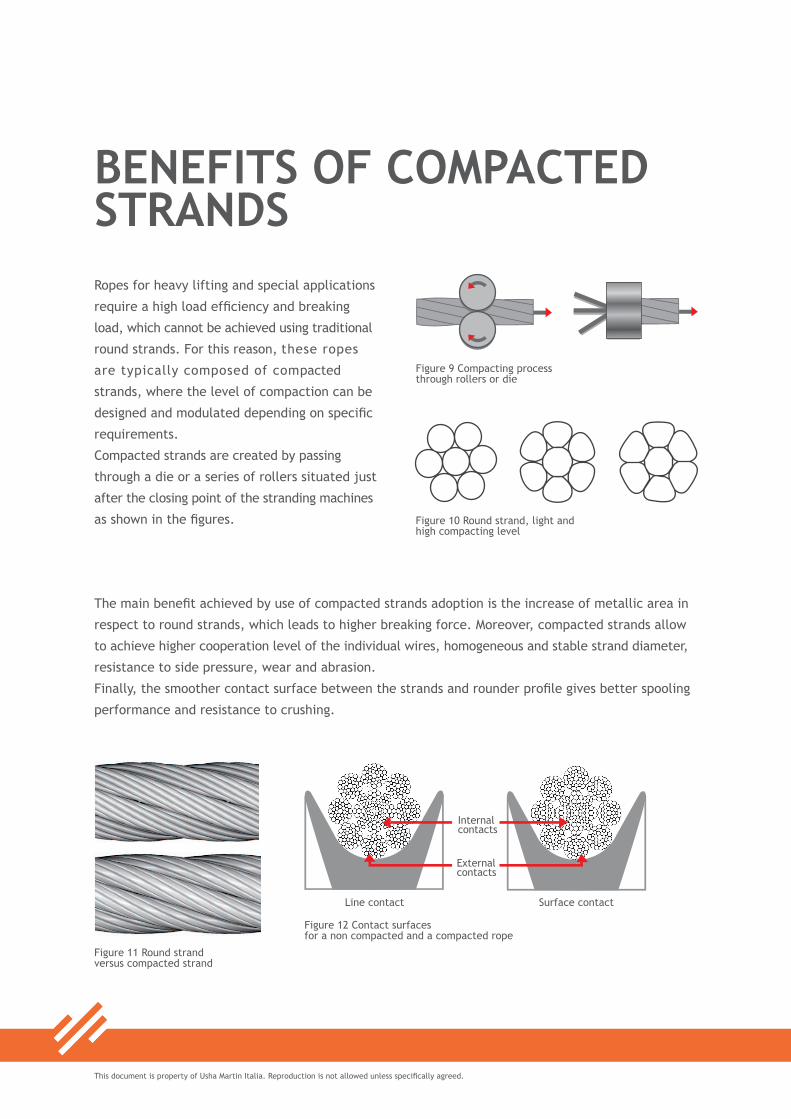
Ropes for heavy lifting and special applications
require a high load efficiency and breaking
load, which cannot be achieved using traditional
round strands. For this reason, these ropes
are typically composed of compacted
strands, where the level of compaction can be
designed and modulated depending on specific
requirements.
Compacted strands are created by passing
through a die or a series of rollers situated just
after the closing point of the stranding machines
as shown in the figures.
BENEFITS OF COMPACTED STRANDS
Figure 10 Round strand, light and high compacting level
The main benefit achieved by use of compacted strands adoption is the increase of metallic area in
respect to round strands, which leads to higher breaking force. Moreover, compacted strands allow
to achieve higher cooperation level of the individual wires, homogeneous and stable strand diameter,
resistance to side pressure, wear and abrasion.
Finally, the smoother contact surface between the strands and rounder profile gives better spooling
performance and resistance to crushing.
Figure 11 Round strand versus compacted strand
Figure 9 Compacting process through rollers or die
Figure 12 Contact surfaces for a non compacted and a compacted rope

09
This document is property of Usha Martin Italia. Reproduction is not allowed unless specifically agreed.
Figure 14 Birdcage deformation
Figure 15 Core protrusion
FLEET ANGLE AND PLASTIC IMPREGNATED CORE ROPESRope routing must be carefully considered to
prevent early damage: one of the most critical
factors is the presence of deflection (i.e. fleet)
angles between two sheaves or from the drum
to the spooler.
When fleet exists, the rope is induced to roll
and slide into the groove, causing shortening
and increasing of the lay length and possible
permanent distortion of the rope structure,
such as birdcage or core protrusion.
Fleet angle should never exceed 2°, it can be
increased up to 4° with the adoption of plastic
impregnated core ropes.
In this type of ropes, plastic is applied to the core
after its closing and is lightly heated and softened
before final closing in order to create a connection
between outer strands and core strands.
The plastic layer must not work as a cushion
(see left sketch), but must allow steel over
steel contact between the core and the
outer strands (see right sketch). This ensures
long-lasting radial stiffness and rope stability.
Figure 16 Cushion layer versus plastic impregnated core
Figure 13 Fleet angle during spooling and rope rolling

This document is property of Usha Martin Italia. Reproduction is not allowed unless specifically agreed.
Figure 17 Stress - strain curve for a wire rope
When a rope is subjected to axial loads, the
elasticity of the material causes elongation
and consequential diameter reduction.
The first graph shows the relationship between
stress (ratio between load and metallic area)
and strain (ratio between elongation and initial
sample length). The slope of the curve is Young
modulus “E”, which multiplied by the metallic
section “A” gives the axial stiffness “EA”.
In the first phase of its use (up to point 1),
rope shows a certain permanent stretch due to
the stabilization of the individual wires.
After this step, the trend is basically linear up
to the achievement of yield point (points 3 and
4), from which permanent plastic deformation
takes place, until the load reaches the actual
rope breaking force.
A typical example of relationship between rope
oversize (ratio between actual and nominal
diameter) is indicated in the second graph.
After training, every rope shows a permanent
diameter reduction due to the stabilization
of its structure. The initial diameter and the
consequent reduction must be such to allow
smooth installation on the drum and good
spooling.
ROPE BEHAVIOUR UNDER LOAD
Figure 18 Rope oversize versus load

11
This document is property of Usha Martin Italia. Reproduction is not allowed unless specifically agreed.
ROTATIONAL CHARACTERISTICS Being composed by helically laid elements,
each rope has the natural tendency to twist
when subjected to axial loads.
The level of twist is dependant on the
geometrical arrangement and can be reduced
by compensating the core tendency to rotate
in one direction with an opposite tendency of
the outer layer, as typically applied to spin
resistant and non rotating ropes.
Ropes are conventionally classified based on
the number of turns that a portion with length
of 1000 times the nominal rope diameter would
make when pulled at 20% MBF (see figure):
1. Non rotating: less than 1 turn
2. Low rotation: from 1 to 4 turns
3. Spin resistant: from 4 to 10 turns
4. Not non rotating: more than 10 turns
Figure 19 Rope classification based on number of turns
Each rope is characterized by torque factor,
which is used in the calculations when both
ends of the rope are fixed, and rotation factor
(expressed in degrees/lay), which is used
when one end is free to rotate.
Both torque factor and rotation factor
strongly decrease after rope stabilization and
are negligible if the rope is always used at
same working load and lifting height.
Figure 20 Torque factor for non rotating and six strand ropes
Figure 21 Rotation for different rope constructions

This document is property of Usha Martin Italia. Reproduction is not allowed unless specifically agreed.
In case of single fall lifting a non rotating rope
is typically recommended, while in case of
multi-part reeving arrangement, rope type
has to be selected depending on height of lift,
block configuration and loading.
A wrong rope selection or improper installation
and training can cause cabling phenomenon,
which can lead to permanent rope deformation,
like waviness, and severe operations issues.
The maximum lifting height for a given rope
torque factor “t” can be briefly calculated
using the approximate formulas shown in the
sketch (all dimensions are in m).
BLOCK STABILITY AND USE OF SWIVEL
In case of special block arrangement, please
contact us for a custom evaluation.
When operating a non rotating rope in single
fall mode, a swivel can be used to relieve the
rope of any induced rotation resulting from
angular deflections at a sheave or drum.
Swivels must not be used with not non rotating
ropes, like 6 strand, as it would cause rope
unlay, severe reduction of its breaking force
and secondary fatigue of the steel core, not
detectable during inspections.
Figure 22 Multiple fall lifting

13
This document is property of Usha Martin Italia. Reproduction is not allowed unless specifically agreed.
Figure 23 Calculation of maximum lifting height
Figure 24 Rope waviness
Figure 25 Example of swivel

This document is property of Usha Martin Italia. Reproduction is not allowed unless specifically agreed.
WIRE ROPE LUBRICATION
Proper lubrication is essential to maintain rope
performance in use, protect it against corrosion
and preserve its service life.
Good quality lubricants are characterized by
high adherence to steel in order to withstand
passage over the reeving system, light colouring
which will not obstruct the detection of possible
rope damage and high compatibility with other
products, which is particularly important for
vessels operating globally.
Drop point has to be high enough to tolerate
rope storage and operation in warm environment,
but with a safety borderline that is sufficient
to detect rope overheating during the use of
special devices such as heave compensators.
Since steel can suffer permanent deterioration
if subjected to high temperatures for extended
periods, a good temperature limitation and
consequent drop point is approximately 80°C.
Lubricant can be applied during different
manufacturing phases: stranding, core closing
and final closing.
When applied during stranding, the lubricant
is firmly engaged within the rope structure and
reduces friction between the wires. If applied
during core closing it creates a barrier against
external elements penetration and if applied
during final closing it further increases protection
against corrosion.
The quantity of lubricant applied during rope
manufacture has to be carefully evaluated on
the basis of rope use and working environment.
Figure 26 Example of rope with very low outer lubrication

15
This document is property of Usha Martin Italia. Reproduction is not allowed unless specifically agreed.
If insufficient lubricant is applied, the rope
will not be adequately protected, however an
excess of lubricant may be squeezed out of
the rope during installation and use, thereby
creating environmental and safety issues.
This has to be carefully considered in case of
boom hoist ropes operating on offshore vessels,
which run over reeving systems composed of a
high number of sheaves.
Before rope installation and during rope use,
the lubrication level must be periodically
inspected to detect any overall or localised
faults and, where required, relubrication can be
performed by using appropriate pressure devices.
For ropes operating subsea, lubricant should
be applied during deployment in order to fill
the strands gaps and prevent water penetration
and trapping.
Figure 27 Typical lubrication levels
The most typical levels of lubrication are
shown in the following figure:
• the first image refers to very small size
ropes, with lubrication applied only during
stranding
• the second figure refers to ropes for
industrial lifting, with lubrication applied
during stranding and core closing
• the third figure refers to ropes for marine
environment applications, with lubrication
also applied during final closing operations.
This is the most frequent option for oil and
gas applications
• the fourth image shows a very high
amount of lubricant, required for ropes
operating subsea or dealing with very
severe environmental conditions

This document is property of Usha Martin Italia. Reproduction is not allowed unless specifically agreed.
After receipt, the rope should be immediately
checked to verify its identity and condition
and should not be used without the possession
of adequate documentation and certificates.
The Certificate of Conformity by the manufacturer
should be stored in a safe designated place in
order to quickly identify the rope and carry
out periodic inspections.
During loading, transferring and unloading
operations, rope reels or coils should be
properly handled using slings or lifting beams.
REEL RECEIPT AND STORAGE
Figure 28 Rope handling recommendations
Slings must have an adequate length to avoid
flange ends overstress during reel lifting.
The rope should be checked to verify that it is
not damaged when unloaded and transported to
storage site and should not come into contact
with parts of the lifting devices, like hooks and
forks.
Some recommendations for rope handling are
indicated on specific labels applied on the reels.

17
This document is property of Usha Martin Italia. Reproduction is not allowed unless specifically agreed.
Storage conditions are essential to prevent
rope damage: it should be avoided to keep the
rope in very warm or humid environment, as
this could break down the effectiveness of native
lubrication and accelerate the deterioration
process. If lubricant has the tendency to drain
due to high temperature, the reel should be
periodically rotated to maintain a homogeneous
distribution.
The rope should not be stored in places which
could be affected by chemical agents, corrosive
matters or accidental damages and, if stored
outside, the reel should be positioned in order
to avoid direct contact with the ground and
covered with waterproof material.
The rope marking should be clearly detectable
and readable in order to safely and quickly
identify the reel.
Figure 29 Reel handling
This document is property of Usha Martin Italia. Reproduction is not allowed unless specifically agreed.
During manufacturing process, the strands can
be preformed in order to get a helical profile
just before closing and improve rope stability
and handling. Similar purpose can be achieved
through postforming, which consists of the
passage of the rope through a series of rollers.
With the exception of very specific applications,
preforming and postforming level must be such
to stabilize the rope without reaching extreme
levels, as this would make the rope very faint
during use.
Therefore, unless the rope has been subjected
to complete preforming, it will have the
tendency to unlay when cut.
For this reason, serving shall be applied before
rope cutting to keep strands in position and
it has to be performed carefully, as its failure
may cause injuries or rope permanent damages.
Serving must be also performed before socketing
and in this case it has to allow socket medium
penetration between the rope and the socket bore.
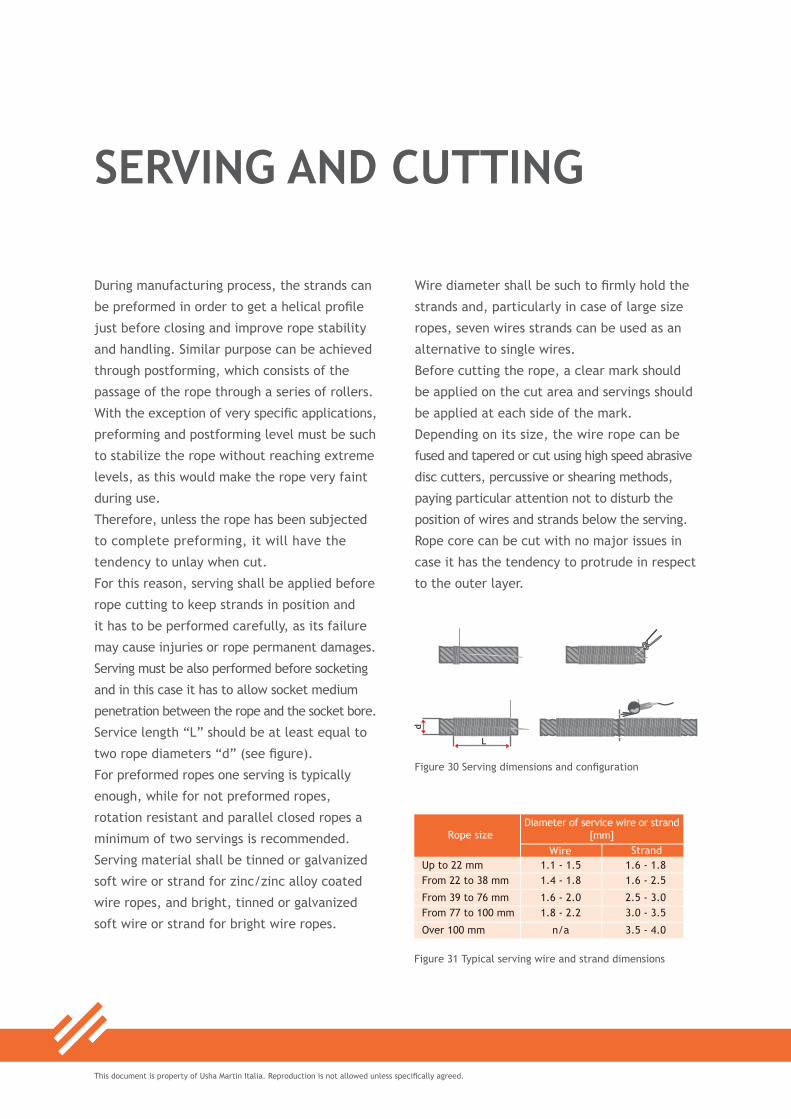
Service length “L” should be at least equal to
two rope diameters “d” (see figure).
For preformed ropes one serving is typically
enough, while for not preformed ropes,
rotation resistant and parallel closed ropes a
minimum of two servings is recommended.
Serving material shall be tinned or galvanized
soft wire or strand for zinc/zinc alloy coated
wire ropes, and bright, tinned or galvanized
soft wire or strand for bright wire ropes.
SERVING AND CUTTING
d
L
Figure 30 Serving dimensions and configuration
Wire diameter shall be such to firmly hold the
strands and, particularly in case of large size
ropes, seven wires strands can be used as an
alternative to single wires.
Before cutting the rope, a clear mark should
be applied on the cut area and servings should
be applied at each side of the mark.
Depending on its size, the wire rope can be
fused and tapered or cut using high speed abrasive
disc cutters, percussive or shearing methods,
paying particular attention not to disturb the
position of wires and strands below the serving.
Rope core can be cut with no major issues in
case it has the tendency to protrude in respect
to the outer layer.
Figure 31 Typical serving wire and strand dimensions

19
This document is property of Usha Martin Italia. Reproduction is not allowed unless specifically agreed.
Ropes can be supplied on coils or reels depending
on size and customer requirements.
If the rope is supplied on a coil, it should be
placed on the ground and rolled out straight,
avoiding contamination with dust, grit, moisture
or other harmful material.
The rope should never be pulled away from a
stationary coil as this will induce turns into the
rope and form kinks (see figure).
ROPE PAY OUT
If the coil is too large to be physically handled, it may need to be placed on a turntable to pay it out
as the end of the rope is pulled away from the coil.
If the rope is supplied on a reel, a shaft of adequate strength should be passed through the reel
bore and the reel should be placed in a suitable stand which allows it to rotate and be braked to
avoid overrun during installation.
If a loop forms in the rope it should not be allowed to tighten to form a kink.
The reel stand should be mounted in a way that avoids reverse bend during reeving: for a drum with
an underwind rope, take the rope off the bottom of the supply reel.
Underwind is also preferable in respect to overwind, as it gives higher stability to the stand and less
risk of overturn.
When releasing the outboard end of the rope from the supply reel or coil, this should be done in a
controlled manner.
Figure 32 Rope kink and associated deformation
Figure 33 Recommendations for rope pay out

This document is property of Usha Martin Italia. Reproduction is not allowed unless specifically agreed.
ROPE TERMINATIONS
Ropes can be supplied with different end
terminations depending on customer requirements.
Temporary end connections must be used only
for rewinding or installation, while permanent
end connections can also be used for actual
operations.
Permanent connections allow the Safe Working
Load to be maintained and are characterized
by a specific efficiency depending on the
connection type, which varies from 100% for
resin sockets to 80% for wedge sockets.
Temporary end connections must not be used
as lifting devices, as they are not designed to
ensure Safe Working Load but only to allow
the rope to be moved from the storage reel to
another reel or to the winch drum.
Some examples of end connections are shown
in the following table. Special sockets or
connections can be provided on demand.
Figure 34 Detail of hoist and boom ropes

21
This document is property of Usha Martin Italia. Reproduction is not allowed unless specifically agreed.
Figure 35 Examples of rope terminations
This document is property of Usha Martin Italia. Reproduction is not allowed unless specifically agreed.
Socketing must be performed by trained people
using proper procedures and equipment.
Socketing media can be metal or resin, which
is more extensively used due to ease of
handling and safety. Moreover, heat generated
during metal socketing can affect steel properties
of the rope.
According to EN12927, the length of the tapered
part of a socket shall be at least 5 times the
nominal rope diameter or 50 times the outer
wire diameter and the angle between the
generatrix and the axis of the cone shall be
from 5° to 9°.The socket basket neck diameter
shall be from 1,2 up to 1,3 times the rope
nominal diameter and shall have a cylindrical
portion long from 0,25 up to 0,5 times the
rope nominal diameter.
The internal socket profile must not have grooves,
as these would reduce resin penetration.
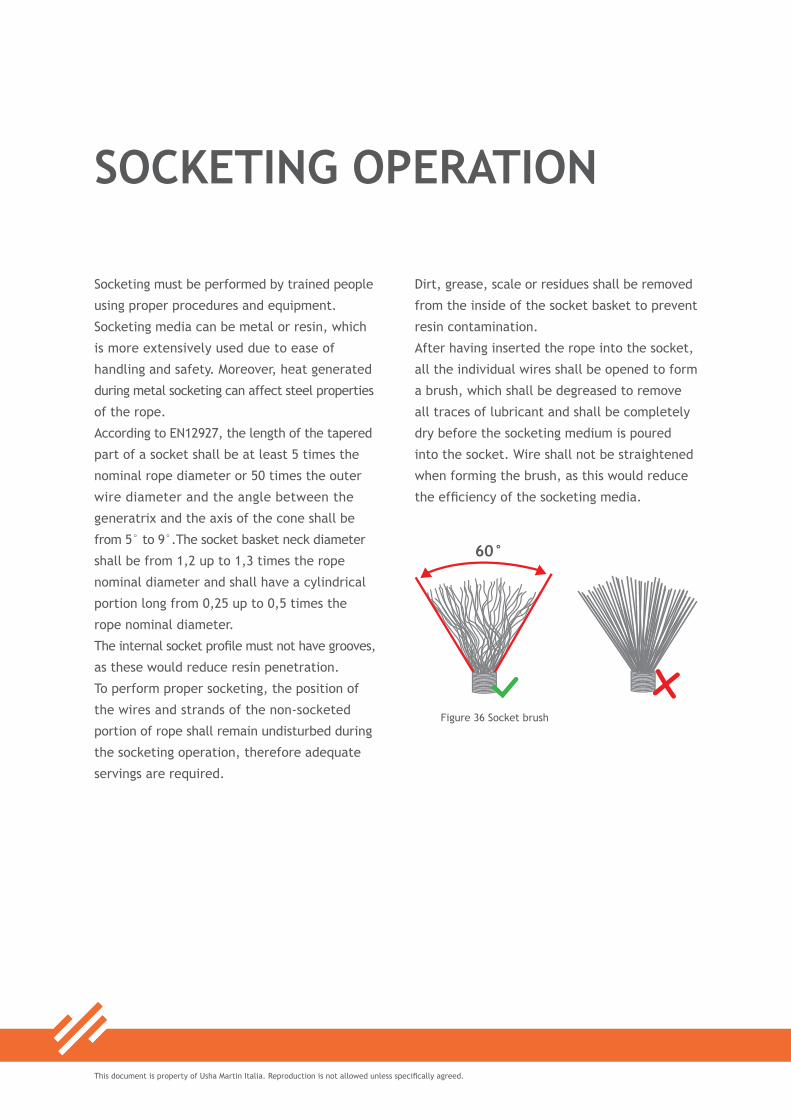
To perform proper socketing, the position of
the wires and strands of the non-socketed
portion of rope shall remain undisturbed during
the socketing operation, therefore adequate
servings are required.
SOCKETING OPERATION
Figure 36 Socket brush
Dirt, grease, scale or residues shall be removed
from the inside of the socket basket to prevent
resin contamination.
After having inserted the rope into the socket,
all the individual wires shall be opened to form
a brush, which shall be degreased to remove
all traces of lubricant and shall be completely
dry before the socketing medium is poured
into the socket. Wire shall not be straightened
when forming the brush, as this would reduce
the efficiency of the socketing media.

23
This document is property of Usha Martin Italia. Reproduction is not allowed unless specifically agreed.
The wires shall be evenly distributed around
the circumference within the socket basket
and the area where the rope enters the bore
of the socket shall be sealed with a material
that prevents leakage of resin and that shall
be removed after socketing. Before starting
the operation, the socket must be aligned with
the rope axis.
The operator shall follow the resin manufac-
turer’s instructions, resin system packages or
kits shall not be sub-divided or used after the
expiry date indicated on the container or out
the prescribed temperature range.
The socket shall be filled from a single pouring
until the basket is full: the approximate resin
content in cc for a standard spelter socket can
be calculated using the formula in the sketch
(cone dimensions are in cm).
During the pouring and topping-up operation
and early stages of gelling, it is essential that
possible leaks are identified and stopped, as
such leaks may generate cavities near the neck
of the brush.
The resin mixture shall be allowed to harden
after gelling and the socket shall not be moved
until the resin has hardened. Some resins
contain a coloring component which turns into
blue during gelling.
Wires protruding after hardening due to resin
loss of volume helps to verify the proper wires
distribution into the cone and does not need to
be covered or removed.
Figure 37 Resin content and cone dimensions

This document is property of Usha Martin Italia. Reproduction is not allowed unless specifically agreed.
Rope spooling and installation should be carried
out in accordance with a detailed plan issued
by the user of the rope to prevent safety
hazards and early rope damage.
The installation tension should be at least the
highest value between 2% of the rope MBF or
10% of rope SWL.
This tension can be obtained directly using
the spooling device or later during training
stage, depending on rope size and equipment
availability.
Standard rope reels are designed for
transportation and storage, therefore they
can bear a limited amount of pulling tension,
which is approximately 3 times the reel diameter
for steel reels, 0.5 times the reel diameter for
wood reels (e.g. 1.5 meter steel reel can bear
up to 4.5 tons, 1.5 meter wood reel can bear
un to 0.75 tons) up to a maximum of 10 tons
using two spindles for each flange.
ROPE INSTALLATION AND TRAINING
Figure 38 Broken wire due to improper handling
If higher tension has to be applied, the rope
has to be spooled on an intermediate reel or
special reel requirements have to be agreed
with the rope supplier.
When first installing the rope, a pilot line
having adequate breaking force to bear
the installation pull should be reeved on the
system and connected to the rope itself.
The pilot line shall have same lay direction
and type as the rope to be installed, otherwise
twist could be induced and permanent damage
could occur.
A swivel should not be used during the installation
of the rope.
It is also important to note that there are
operational limits related to some rope
constructions: as a general guideline, the
maximum operating depth is 1300 meters for 6
strand ropes and 1000 meters for 8 strand ropes.

25
This document is property of Usha Martin Italia. Reproduction is not allowed unless specifically agreed.
During pulling into the system, the rope
should be carefully monitored and it should
not obstructed by any part of the structure that
may bring damage and result in a loss of control.
The equipment should be run at limited speed
to facilitate gradual rope stabilization.
Full load should never be applied during this
stage.
During spooling, continuous check has to be
performed to verify that no slack occurs in
the rope or cross-laps of rope develop at the
drum, as irregular coiling would inevitably
result in severe surface wear and rope distortion.
In multilayer drums, the crossover area (see
figure) must be carefully monitored.
A good spooling will show tight wraps and
uniform rope arrangement also in the crossover
zone and up to the last layers, which will reduce
the risk of crushing, cut-in or early formation
of broken wires.
Training is also essential to stabilize rope
dimensions and to optimize rope lifetime and
performance.
It is performed by lifting an adequate load for
at least three times using the full rope length,
excluding the safety wraps which must always
remain on the drum: the load automatically
generates proper backtension, diameter
stabilization and torque factor reduction.
Figure 39 Crossover area

This document is property of Usha Martin Italia. Reproduction is not allowed unless specifically agreed.
Applicable regulations give indications to
ensure that lifting equipment is safe when
new, that it is used safely and that it remains
safe for use.
Equipment and accessories are marked with
their own safety working loads and must never
be used out of the prescribed interval. They
should always be thoroughly examined according
to adequate inspection procedures, as well
as before first use, when moved to different
locations in respect to the original one and
each time unexpected events which may affect
safety occur.
Similar indications apply to wire ropes, which
should always be handled, maintained and
inspected by competent persons using proper
procedures (see also chapters related to wire
rope inspection).
When bent over stationary pins or sheaves,
rope minimum breaking force is affected in
respect to linear load conditions depending on
D/d ratio, thus reducing its efficiency (see figure).
LIFTING OPERATIONS
For moving parts, further reduction must be
considered due rope internal friction and
efficiency of the rotating parts.
The efficiency of sheaves should also be
considered when calculating the lead line load.
In case of systems having same number of
rotating sheaves and parts of line (e.g. 2 falls
and two rotating sheaves, like in the first
sketch), the lead line load can be calculated
by dividing the load by the efficiency coefficient
(e.g. as per the following table: lifting 80 tons
in 2 parts mode with roller bearing sheaves will
give a lead line load of 80 /1.94 = 41.2 tons).
If additional rotating sheaves are used (see
second sketch), unless otherwise specified
the resulting line load should be divided by
0.96, 0.98 or 0.99 (plain, roller bearing or high
efficiency sheaves) times the number of extra
sheaves in respect to the rope bearing parts.

27
This document is property of Usha Martin Italia. Reproduction is not allowed unless specifically agreed.
Figure 40 Reduction in rope efficiency in case of bent over stationary components
Figure 42 2 Falls with 2 rotating sheaves and with an extra sheave
Figure 41 Example of lead line factors

This document is property of Usha Martin Italia. Reproduction is not allowed unless specifically agreed.
ROPE WINDING OVER SHEAVESWhen a rope runs over the reeving, its strands
are forced to modify their relative position to
maintain contact with the system.
If the reeving arrangement is not properly
designed, the strands cannot recover their
natural location in the passage between
adjacent components, therefore the rope can
suffer premature fatigue or localized damage.
This particularly applies in case of reverse
bending configuration, where the strands are
stretched and compressed between two sheaves.
To avoid permanent damage, for complete
reverse bending (see first sketch) the minimum
recommended distance is about 100 times the
rope diameter.
For partial reverse bending (see second
sketch), a lower distance could be accepted.
Both in the case of reverse and simple
bending, the sheaves have to be properly
designed in terms of size, groove configuration
and hardness.
Figure 43 Reverse bending and partial reverse bending
Figure 44 Detail of rope winding
29
This document is property of Usha Martin Italia. Reproduction is not allowed unless specifically agreed.
As already mentioned, the typical minimum
recommended bending ratio is 20 times the
rope nominal diameter, while the recommended
groove oversize can vary from 1.06 to 1.1
times the rope diameter.
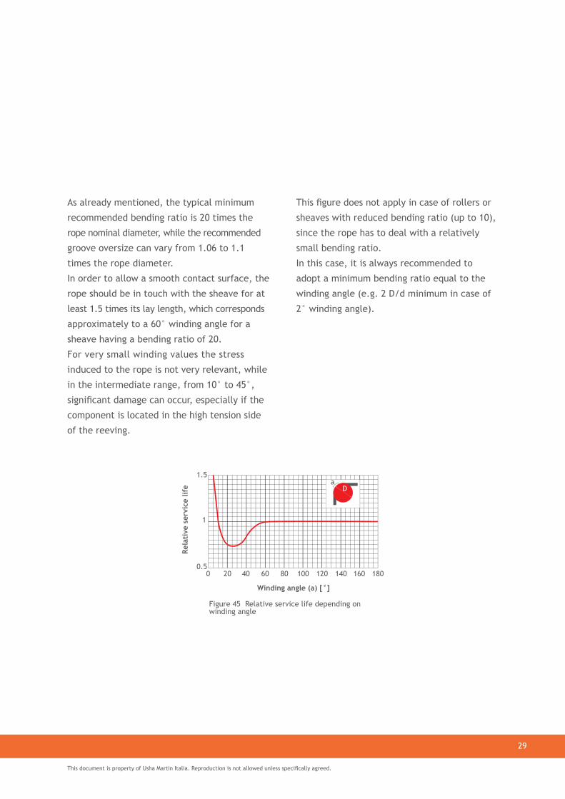
In order to allow a smooth contact surface, the
rope should be in touch with the sheave for at
least 1.5 times its lay length, which corresponds
approximately to a 60° winding angle for a
sheave having a bending ratio of 20.
For very small winding values the stress
induced to the rope is not very relevant, while
in the intermediate range, from 10° to 45°,
significant damage can occur, especially if the
component is located in the high tension side
of the reeving.
This figure does not apply in case of rollers or
sheaves with reduced bending ratio (up to 10),
since the rope has to deal with a relatively
small bending ratio.
In this case, it is always recommended to
adopt a minimum bending ratio equal to the
winding angle (e.g. 2 D/d minimum in case of
2° winding angle).
Figure 45 Relative service life depending on winding angle
This document is property of Usha Martin Italia. Reproduction is not allowed unless specifically agreed.
When the rope is bent over a component of
the reeving system, it generates pressure
which is dependent on its diameter, the
diameter of the component itself and the
applied tension.
In order to ensure proper performance, the
groove material should give a smooth and
hard contact.
In case of inadequate material selection, the
groove steel will be locally hardened, with
consequent embrittlement and detachment of
steel flakes, which can damage both the rope
and the component itself.
The typical recommendation is to use hardened
steel with approximate 300 HB value.
In case of synthetic sheaves, the yield point
of the material should be higher than the
exerted pressure.
The nominal average pressure can be calculate
using the formula shown in the next page.
CONTACT PRESSURE BETWEEN ROPE AND SHEAVES
Multistrand and non rotating ropes ensure a
better pressure distribution than six strand
ropes, as the higher number of outer strands
generates a wider contact surface (see figures
of the next page).
Compacted strands and Lang’s lay ropes
further extend the contact surface.
A good groove dimension is also important to
achieve a reduced pressure.
The figures of the next page show different
configurations depending on various groove
oversize: narrow, well dimensioned and
large groove.

31
This document is property of Usha Martin Italia. Reproduction is not allowed unless specifically agreed.
Figure 46 Rope pressure over a sheave
Figure 48 Pressure distributionfor narrow, well dimensioned and large grooves
Figure 47 Pressure distribution of 6 strand and non rotating rope

This document is property of Usha Martin Italia. Reproduction is not allowed unless specifically agreed.
The main purpose of lubrication is to maintain
rope performance in use and protect it against
corrosion, which can determine rope discard
when reaching a high severity rating.
Corrosion affects not only the residual
breaking force, but also wire ductility and
mechanical characteristics, therefore it should
be carefully considered when inspecting a rope.
Unless unexpected events, the protection
provided by the original manufacturing lubricant
is enough to prevent rope corrosion during
shipment, storage and first period of use.
Lubricant conditions must be periodically
checked depending on rope working type and
environmental conditions.
ROPE RELUBRICATION
Before relubrication, rope must be cleaned to
remove scales, moisture and other contaminants.
Lubrication must be carried out on dry and clean
rope using a lubricant compatible with the
original one and whose amount is not excessive,
as this would make difficult to inspect the
rope and could lead to accumulation of debris
which could generate abrasions.
Some typical lubrication modes are shown in
the following figure.
Figure 49 Typical lubrication modes

33
This document is property of Usha Martin Italia. Reproduction is not allowed unless specifically agreed.
Fatigue damage is a typical phenomenon which
is not caused by a single event, but by repeated
bending, tension and rotational stresses: since
the working life of wire ropes generally involves
several passages over drum and sheaves, this
damage has to be carefully considered during
operations.
The first factor to be considered with respect
to fatigue damage is the working load: taking a
safety factor of 5 as a reference point, relative
service life of rope operating in the same system
with different loads is shown in the first figure.
Fatigue damage occurs gradually and becomes
evident when it reaches a point where it has
caused a high number of broken wires and
consequent wire elongation, which quickly
evolves until the rope gets to discard criteria.
The typical trend of fatigue growth is shown
in the second figure: it is clear that there is
a rapid increase in the curve slope after a
certain threshold, and this is strongly affected
by working load.
BENDING FATIGUE
Figure 50 Effect of safety factor on service life
Figure 51 Fatigue progression

This document is property of Usha Martin Italia. Reproduction is not allowed unless specifically agreed.
FACTORS AFFECTING BENDING FATIGUESince fatigue is an inherent phenomenon, it
cannot be eliminated, however it can be slowed
down by adopting, when possible, particular
features with respect to rope design and
system layout.
With respect to rope design, the most effective
way to reduce fatigue evolution is by avoiding
the use of extremely high strength wires
(over 2160 N/mm²).
As already mentioned, this improves steel
ductility allowing a better resistance to repeated
bending cycles.
Contrary to expectation, rope composed of
many small wires may not have higher fatigue
resistance, especially when working at low
safety factor.
In terms of system design, there are several
strategies that can be adopted to preserve
rope life.
The first tool is to increase the bending ratio of
the component over which the rope is running.
This can have some practical limitations,
especially when dealing with large size ropes.
Another approach which can be adopted
without major expense is the selection of
proper groove size. The recommended value
is approximately 1.08 times the nominal rope
diameter, depending on rope type and possible
fleet angle.
Fleet angle must be always considered and
limited, as it creates a stress within the
structure of the rope and contributes to fatigue
build up.
In case of fleet angle, groove oversize should be
increased to 1.10 or more in order to facilitate
the passage of the rope through the groove.

35
This document is property of Usha Martin Italia. Reproduction is not allowed unless specifically agreed.
Figure 52 Effect of bending ratio on service life
Figure 53 Effect of fleet angle on service life Figure 54 Effect of groove ratio on service life

This document is property of Usha Martin Italia. Reproduction is not allowed unless specifically agreed.
GUIDELINES FOR ROPE INSPECTIONWire ropes must be periodically inspected
following regulations (e.g. ISO 4309) and
internal procedures to assess rope deterioration
due to regular use or unexpected events and
to ensure safe working conditions.
Inspections can be carried out with the aid of
visual or magnetic devices: in this case, it is
recommended to perform an initial inspection
before rope use to have a baseline for future
comparisons.
Each rope shall be inspected along its entire
length or, at the discretion of the competent
person, along the working length plus at least
five wraps on the drum. In this case, if a greater
working length is subsequently foreseen to be
used, that additional portion should also be
inspected.
The frequency of inspections depends on
regulations, type of crane and environment,
results of previous examinations, load spectrum
and experience related to similar ropes and
systems.
The main modes of deterioration are: broken
wires or strands, decrease in rope diameter,
corrosion, deformation, mechanical or heat
damage and change in elastic behaviour of
rope under load.
Figure 55 Ropes used for construction cranes

37
This document is property of Usha Martin Italia. Reproduction is not allowed unless specifically agreed.
Figure 56 Areas requiring detailed inspection
Crossover and max fleet angle
Block and head heaves
Compensating sheaves
The following areas have to be inspected with
particular care:
• drum anchorage and any section close and
in correspondence to rope termination
• in case of repetitive operations, any part
of the rope that lies over a sheave during
crane working
• rope portion which lies over a compensating
sheave
• cross-over zones on multilayer drums
• rope sections subjected to reverse bending
over sheaves or rollers
• section subjected to external damage, like
abrasion or heat.
Terminations, clamps and securing ferrules
should be also inspected with special care to
detect possible looseness due to vibrations,
cracks, distortion, wear or corrosion.
After each periodic inspection, the competent
person shall provide a rope inspection record
and state a maximum time interval that shall
not be exceeded before the next periodic
inspection takes place.
The following sketch shows some examples
of typical points which require special care
during inspection.

This document is property of Usha Martin Italia. Reproduction is not allowed unless specifically agreed.
Before installing the new rope, the condition
and dimensions of interface parts, like drums,
sheaves and rope guards, should be checked
to verify that they are within the operating
limits as specified by the original equipment
manufacturer.
The groove diameter, which can vary from
5% to 10% above the nominal rope diameter,
should be checked using a sheave gauge (see
figure). Sheaves should also be checked to
ensure that they are free to rotate.
When grooves become excessively worn, they
can be re-machined if sufficient wall thickness
will remain in the underlying material after
the machining has been carried out.
Improper groove finishing can generate irregular
rope routing and derailing over the sheave.
INSPECTION OF GROOVES AND SHEAVES
Figure 58 Bending ratio between rope and sheave
The recommended bending ratio D/d (e.g.
ratio between diameter of the component
and rope nominal diameter) depends on rope
construction. Some typical values for crane
applications are shown in the following table
and are determined based on uniform stress
distribution of rope, strands and individual
wires.
Other values can be found on specific regulations.
Figure 57 Grooves inspection: correct size, narrow and large groove
Figure 59 Examples of recommended bending ratios for cranes

39
This document is property of Usha Martin Italia. Reproduction is not allowed unless specifically agreed.
TYPICAL ROPE DAMAGES AND RECOMMENDED ACTIONS
Listed actions are for general purpose only, please contact Usha technical assistance for specific recommendations.

This document is property of Usha Martin Italia. Reproduction is not allowed unless specifically agreed.
Rope conditions have to be clearly assessed by
a competent person based on discard criteria
provided by regulations and internal procedures.
Discard criteria depend on the nature,
occurrence and location of broken wires
and on the rope construction and are based
on number of visible broken wires, diameter
variation, corrosion and distortion or a
combination of all these factors.
Number of visible broken wires takes in account
only the breaks due to regular use, that indicate
fatigue pile up and approaching of end of rope
safe life, therefore breaks due to improper
handling may not be considered in this count if
not affecting safety conditions.
Breaks protruding from the rope can be
removed if there is the risk that they generate
further damage to the equipment or to the
rope itself.
Figure 60 Crown and valley breaks due to fatigue
If groups of broken wires are found in a section
of rope which does not spool on and off the drum
and breaks are concentrated in adjacent strands,
it might be necessary to discard the rope.
It shall be discarded as well if two or more
wire breaks are found at a termination or
concentrated in the valleys in a rope lay
length, as this could indicate the beginning of
fatigue phenomenon.
If breaks occur randomly in rope sections
running through sheaves, spooled on and off
a single layer drum or on crossover points of
a multilayer drum, the maximum amount is
determined by specific regulations (e.g. ISO
4309). Some examples of maximum allowed
breaks for different rope use and constructions
are shown in the following table.
DISCARD CRITERIA FOR VISIBLE BROKEN WIRES

41
This document is property of Usha Martin Italia. Reproduction is not allowed unless specifically agreed.
The numbers depend on the assumption that
outer wire breaks correspond to a certain
number of inner wire breaks.
Typically, the number of inner broken wires
due to use of a Lang lay rope is higher than
the number of outer broken wires, therefore
damage detection is harder and the number of
outer allowed breaks must be lower.
On the other hand, in ordinary lay ropes more
breaks occur on the outer surface, therefore
they are more detectable and the allowed
number is higher than the Lang lay value.
For non rotating ropes this difference is not
remarkable due to their geometrical structure,
therefore there is no distinction due to lay
direction.
Breaks distribution along the rope can indicate
fatigue beginning, therefore the number of
broken wires over a significant rope length
(e.g. 30d) is not proportional to the number
of localized broken wires in a specific portion
(e.g. 6d), which could be due to other causes
to be specifically investigated.
Figure 61 Maximum number of visible broken wires for typical rope constructions

This document is property of Usha Martin Italia. Reproduction is not allowed unless specifically agreed.
Diameter shall be periodically measured and
compared to the initial reference value (i.e.
recorded measurement taken immediately
after receipt) to detect uniform or localized
variations.
Diameter decrease has to be calculated using
the below formula.
In case of uniform decrease, the maximum
allowed value is 5% in respect to nominal
diameter for non rotating ropes, 7.5% for other
rope constructions with steel core, 10% for
fibre core ropes.
A clear localized decrease indicates a severe
failure of rope core and leads to immediate
rope discard.
Also in case of break of a complete strand,
rope has to be immediately discarded.
Ropes showing deformations like basket,
core or strand protrusion or distortion, kink
or tightened loop shall be evaluated and can
remain in service if the damaged portion can
be removed and if the remaining part of rope
is still suitable for use.
DISCARD CRITERIA FOR DIAMETER DECREASE, DEFORMATION AND CORROSION
Other damages, like flattened portion or
permanent bend, may not be cause of immediate
discard, but they have to be inspected with
higher frequency, as the affected portions are
likely to deteriorate and show broken wires at
faster rate than usual.
Waviness should be assessed using a straight
bar and considering the gap between the rope
and the cut surface (see figure): the maximum
allowed gap “g” is 1/3 the rope nominal
diameter “d” if the deformation affects a
portion not running over sheaves or spooled on
the drum, otherwise it has to be reduced to 1/10.
Figure 62 Waviness assessment

43
This document is property of Usha Martin Italia. Reproduction is not allowed unless specifically agreed.
Corrosion should be evaluated after having
wiped the rope to remove contaminating
particles and should be assessed considering
type and severity.
Rope should be discarded in case of heavy pitting
and slack wires on the external surface, as
well as in case of internal corrosion, indicated
by the presence of debris extruding between
the outer strands.
Rope should also be discarded in case of severe
fretting corrosion, which manifests as a dry
red powder and is caused by the continuous
rubbing between dry wires and consequent
particles oxidation.
Figure 63 Rope showing external corrosion

This document is property of Usha Martin Italia. Reproduction is not allowed unless specifically agreed.
As a general indication, applicable to all types
of working environment, workers must be
properly trained and have all the necessary
equipment and operating procedures to
perform their job safely.
Steel wire rope is a composite product containing
different materials, which can be identified
based on the delivery note, invoice or certificate.
The main component of steel wire ropes
covered by the various parts of EN 12385 is
carbon steel, which may be galvanized or
coated with zinc aluminium alloy.
Other components can be the fibre core, the
lubricant and possible plastic filling or covering.
Ropes produced from carbon, galvanizing coated
or stainless steel wires in the as-supplied
condition are not considered a health hazard.
However, during any subsequent processing
such as cutting, welding, grinding and cleaning,
dust and fumes may be produced which
contain elements that may affect the health
of exposed workers.
HEALTH AND SAFETY INFORMATION
Fibre cores are composed by synthetic or
natural fibres and do not present a health
hazard when handled, except in the unlikely
case that the core may have decomposed into
a dust which may be inhaled.
Also the concentration of toxic fumes from the
cores generated during cutting will be almost
negligible compared with the products generated
by wire and lubricant.
Same risk of toxic fumes inhalation applies to
plastic filling or covering.
The lubricants used in the manufacture of steel
wire ropes normally present minimal hazard to
the user, who should anyway take reasonable
care to minimize skin and eye contact and also
avoid breathing their vapours and mists.

45
This document is property of Usha Martin Italia. Reproduction is not allowed unless specifically agreed.
Lubricants consist essentially of mixtures of oils,
waxes, bitumen, resins, petroleum jelly, gelling
agents and fillers with minor concentrations of
corrosion inhibitors, oxidation stabilizers and
tackiness additives and they are typically solid
at ambient temperature.
To avoid the possibility of skin disorders,
repeated or prolonged contact with mineral
or synthetic hydrocarbons should be avoided
and workers should always wear protective
clothing and gloves.
General and local exhaust ventilation should
be used to keep airborne dust or fumes below
established occupational exposure standards
and operators should wear approved dust and
fume respirators if these values are exceeded.
Protective equipment should be worn during ope-
rations creating eye hazards, as well as gloves and
other protective equipment when required.
A welding hood should be worn when welding
or burning.
In the solid state, steel components of the
rope present no fire or explosion hazard.
Organic elements, like lubricants, natural and
synthetic fibres and other natural or synthetic
filling and covering materials are capable of
supporting fire.
Ropes and components must be disposed of in
accordance with local Regulations.

This document is property of Usha Martin Italia. Reproduction is not allowed unless specifically agreed.
APPENDIX A QUICK CALCULATORQuick calculation for general purpose evaluations or for preliminary design feasibility can be made
using the following formulas and tables, which provide a set of relevant nominal values.

47
This document is property of Usha Martin Italia. Reproduction is not allowed unless specifically agreed.
APPENDIX B DEFINITIONS• BREAKING FORCE1. minimum breaking force (Fmin): specified
value in kN, below which the measured breaking force (Fm) is not allowed to fall in a prescribed breaking force test and normally obtained by calculation from the product of the square of the nominal diameter (d), the rope grade (Rr) and the breaking force factor (K)
2. minimum breaking force factor (K): an empirical factor used in the determination of minimum breaking force of a rope and obtained from the product of fill factor (f) for the rope class or construction, spinning loss factor (k) for the rope class or construction and the constant π/4
3. calculated minimum breaking force (Fc.min): value of minimum breaking force based on the nominal wire sizes, wire tensile strength grades and spinning loss factor for the rope class or construction as given in the manufacturer’s rope design
4. minimum aggregate breaking force (Fe.min): specified value, in kN, below which the measured aggregate breaking force is not allowed to fall in a prescribed test and normally obtained by calculation from the product of the square of the rope diameter (d), the metallic cross sectional area factor (C) and the rope grade (Rr)
5. measured aggregate breaking force (Fe.m): the sum of the measured breaking forces of all the individual wires taken from the rope
6. spinning loss factor (k): the ratio between either the calculated minimum breaking force (Fc.min) and the calculated minimum aggregate breaking force (Fe.c.min) of the rope or the specified minimum breaking force (Fmin) and the specified minimum aggregate breaking force (Fe.min) of the rope, as determined from the ropemaker’s design [amended]
7. measured total spinning loss factor (km): the ratio between the measured breaking force (Fm) of the rope and the measured aggregate breaking force of the rope, before rope making
• COATING1. finish and quality of coating: the
condition of the surface finish of the wire e.g. uncoated (bright), zinc coated, zinc alloy coated or other protective coating and the class of coating, e.g. class B zinc coating, defined by the minimum mass of coating and the adherence of the coating to the steel below
2. mass of coating: the mass of coating (obtained by a prescribed method) per unit of surface area of the uncoated wire, expressed in g/m²
• CORE1. core: central element of a round rope
around which are laid helically the strands of a stranded rope or the unit ropes of a cable laid rope
2. fibrecore(FC): core made from either natural fibres (NFC) or synthetic fibres (SFC) (Note - Fibre cores are normally produced in the sequence fibres to yarns, yarns to strands and strands to rope)

This document is property of Usha Martin Italia. Reproduction is not allowed unless specifically agreed.
• DIMENSIONS1. dimension of round wire or strand: the
diameter of the perpendicular cross-section of the wire or strand
2. dimension of round rope:that diameter which circumscribes the rope cross-section
3. outer wire factor (a): factor used in the calculation of the approximate diameter of the outer wires of the outer strand layer
4. outerwirediameter(δa): the value derived from the product of the outer wire factor and the nominal rope diameter
• GRADE AND TENSILE STRENGTH1. rope grade (Rr): a level of requirement
of breaking force which is designated by a number (e.g. 1770, 1960) (Note - It does not imply that the actual tensile strength grades of the wires in the rope are necessarily of this grade)
2. wire tensile strength grade (R): a level of requirement of tensile strength of a wire and its corresponding range. It is designated by the value according to the lower limit of tensile strength and is used when specifying wire and when determining the calculated minimum breaking force or calculated minimum aggregate breaking force of a rope, expressed in N/mm²
3. wire tensile strength (Rm): the ratio between the maximum force obtained in a tensile test and the nominal cross-sectional area of the test piece, expressed in N/mm²
3. steel core (WC): core made from steel wires arranged as a wire strand (WSC) or as an independent wire rope (IWRC) (Note The steel core and/or its outer strands can also be covered with either fibre or solid polymer)
4. solid polymer core (SPC): core consisting of a solid polymer material having a round shape or a round shape with grooves. It may also contain an internal element of wire(s) or fibre
• CROSS SECTIONAL AREA AND MASS1. fillfactor(f): the ratio between the sum
of the nominal metallic cross-sectional areas of all the wires in the rope and the circumscribed area of the rope based on its nominal diameter
2. nominal metallic cross-sectional area factor (C): factor derived from fill factor and used in the calculation to determine the nominal metallic cross-sectional area of a rope (Note - This can be expressed as C = f π/4)
3. nominal metallic cross-sectional area (A): the product of the nominal metallic cross-sectional area factor (C) and the square of the nominal rope diameter
4. rope length mass factor (W): that factor which takes into account the mass of core and lubricant as well as the metallic elements
5. nominal rope length mass (M): product of the length mass factor and the square of the nominal diameter
•

49
This document is property of Usha Martin Italia. Reproduction is not allowed unless specifically agreed.
• LAY 1. lay length (H): that distance (H) parallel
to the longitudinal rope axis in which the outer wires of a spiral rope, the outer strands of a stranded rope or the unit ropes of a cable-laid rope make one complete turn (or helix) about the axis of the rope
2. lay direction of rope: the direction right (Z) or left (S) corresponding to the direction of the outer strands in a stranded rope in relation to the longitudinal axis of the rope
3. ordinary lay (sZ or zS): stranded rope in which the direction of lay of the wires in the outer strands is in the opposite direction to the lay of the outer strands in the rope (Note - The first letter denotes strand direction; the second letter denotes rope direction)
4. lang lay (zZ or sS): stranded rope in which the lay direction of the wires in the outer strands is in the same lay direction as that of the outer strands in the rope (Note - The first letter denotes strand direction; the second letter denotes rope direction)
• ROPES1. rope construction: the detail and
arrangement of the various elements of the rope
2. rope class: a grouping of ropes of similar mechanical properties and physical characteristics
3. stranded rope: an assembly of several strands laid helically in one or more layers
around a core (single-layer rope) or centre (rotation-resistant or parallel-closed rope) (Note - Stranded ropes consisting of three or four outer strands can, or cannot, have a core)
4. single-layer rope: stranded rope consisting of one layer of strands laid helically around a core
5. rotation-resistant rope: stranded rope designed to generate reduced levels of torque and rotation when loaded (Note - Rotation-resistant ropes generally comprise an assembly of at least two layers of strands laid helically around a centre, the direction of lay of the outer strands being opposite to that of the underlying layer. Ropes having three or four strands can also be designed to exhibit rotational-resistant properties)
6. parallel-closed rope: stranded rope consisting of at least two layers of strands laid helically in one closing operation around a strand or fibre centre
7. compacted strand rope: rope in which the strands, prior to closing of the rope, are subjected to a compacting process such as drawing, rolling or swaging
8. compacted (swaged) rope: rope which is subjected to a compacting (usually swaging) process after closing the rope, thus reducing its diameter
9. cable-laid rope: an assembly of several (usually six) round stranded ropes (referred to as unit ropes) closed helically around a core(usually a seventh rope)

This document is property of Usha Martin Italia. Reproduction is not allowed unless specifically agreed.
• ROPE CHARACTERISTICS1. torque: torsional characteristic, the value
of which is usually expressed in Nm, at a stated tensile loading and determined by test when both rope ends are prevented from rotating (Note - Torsional characteristics can also be determined by calculation)
2. turn: rotational characteristic, the value of which is usually expressed in degrees or turns per unit length at a stated tensile loading and determined by test when one end of the rope is free to rotate
3. fully preformed rope: rope in which the wires in the strands and strands in the rope have their internal stresses reduced resulting in a rope which after removal of any serving, the wires and the strands will not spring out of the rope formation
• STRAND1. strand: an element of rope consisting of
an assembly of wires of appropriate shape and dimensions laid helically in the same direction in one or more layers around a centre (Note - Strands containing three or four wires in the first layer, or certain shaped strands (e.g. ribbon) cannot have a centre)
2. compacted strand: a strand which has been subjected to a compacting process such as drawing, rolling or swaging whereby the metallic cross-sectional area of the wires remains unaltered whereas the shape of the wires and the dimensions of the strand are modified
3. Seale: parallel lay strand construction with the same number of wires in both layers
4. Warrington: parallel lay strand construction having an outer layer containing alternately large and small wires and twice the number of wires as the inner layer
5. Filler: parallel lay strand construction having an outer layer containing twice the number of wires than the inner layer, with filler wires laid in the interstices between the layers
• WIRE 1. outer wires: all wires positioned in the
outer layer of a spiral rope or in the outer layer of wires in the outer strands of a stranded rope
2. inner wires: all wires of intermediate layers positioned between the centre wire and outer layer of wires in a spiral rope or all other wires except centre, filler, core and outer wires in a stranded rope
3. fillerwires: wires used in filler constructions to fill up the interstices between wire layers
4. centre wires: wires positioned either at the centre of a spiral rope or the centres of strands of a stranded rope
5. core wires: all wires of the core of a stranded rope
6. load-bearing wires: those wires in a rope which are regarded as contributing towards the breaking force of the rope
7. serving wire or strand: single wire or strand used for making a close-wound helical serving to retain the elements of a rope in their assembled position

51
This document is property of Usha Martin Italia. Reproduction is not allowed unless specifically agreed.
The following list indicates some of the most
relevant documents about wire ropes definitions,
use, maintenance and inspection.
• EN 12385-1:2009 – Steel wire ropes – Safety
Part 1: General requirements
• EN 12385-2:2008 – Steel wire ropes –
Safety Part 2: Definitions, designation and
classification
• EN 12385-3:2008 – Steel wire ropes – Safety
Part 3: Information for use and maintenance
• EN 12385-4:2008 – Steel wire ropes – Safety
Part 4: Stranded ropes for general lifting
applications
• EN 13411-3:2011 – Terminations for steel
wire ropes – Safety Part 3: ferrules and
ferrule-securing
• EN 13411-4:2011 – Terminations for steel
wire ropes – Safety Part 4: metal and resin
socketing
• EN 13411-5:2011 – Terminations for steel
wire ropes – Safety Part 5: U-bolt wire
rope grips
• EN 13411-6:2011 – Terminations for steel
wire ropes – Safety Part 6: Asymmetric
wedge socket
• EN 13411-7:2011 – Terminations for steel
wire ropes – Safety Part 7: Symmetric wedge
socket
APPENDIX C REFERENCE DOCUMENTS
• EN12927– Part 8 – Magnetic rope testing
• ISO 17558:2006 – Steel wire ropes – Socketing
procedures – Molten metal and resin socketing
• ISO 4309:2010 – Cranes – Wire ropes – Care
and maintenance, inspection and discard
• IMCA M171 – Crane specification document
• IMCA M179 – Guidance on the use of cable
laid slings and grommets
• IMCA M187 – Guidelines for lifting operations
• IMCA M194 – Wire rope integrity management
for vessels in the offshore industry
• IMCA M197 – Guidance on non-destructive
examination (NDE) by means of magnetic
rope testing
• API 9A/ISO 10425:2003 – Steel wire ropes for
the petroleum and natural gas industries
– Minimum requirements and terms of
acceptance
• API RP 9B:2005 – American Petroleum
Institute recommended practice for
application, care and use of wire rope for
oilfield services
• Wire rope technical board – Wire rope
user’s manual 4th edition

This document is property of Usha Martin Italia. Reproduction is not allowed unless specifically agreed.
APPENDIX D EXAMPLES OF STRANDS AND ROPES CONSTRUCTIONS
Single lay 7 (1-6)
19 Seale compactedK19S (1-9-9)
26 Warrington Sealecompacted
K26WS (1-5-5+5-10)
29 Filler29F (1-7-7F-14)
31 Warrington Sealecompacted
K31WS (1-6-6+6-12)
36 Warrington Seale36WS (1-7-7+7-14)
41 Warrington Seale compacted
K41WS (1-8-8+8-16)
25 Filler25F (1-6-6F-12)
6xK36WS - IWRC 6xK36WS - PWRC6xK7 – FC
8x19S - IWRC 10xK19S – IWRC 57xK735xK7
8xK26WS – FC

Notes
................................................................................................................................................................................................................................
................................................................................................................................................................................................................................
................................................................................................................................................................................................................................
................................................................................................................................................................................................................................
................................................................................................................................................................................................................................
................................................................................................................................................................................................................................
................................................................................................................................................................................................................................
................................................................................................................................................................................................................................
................................................................................................................................................................................................................................
................................................................................................................................................................................................................................
................................................................................................................................................................................................................................
................................................................................................................................................................................................................................
................................................................................................................................................................................................................................
................................................................................................................................................................................................................................
................................................................................................................................................................................................................................
................................................................................................................................................................................................................................
................................................................................................................................................................................................................................
................................................................................................................................................................................................................................
................................................................................................................................................................................................................................
................................................................................................................................................................................................................................
................................................................................................................................................................................................................................
................................................................................................................................................................................................................................
................................................................................................................................................................................................................................
................................................................................................................................................................................................................................
................................................................................................................................................................................................................................
................................................................................................................................................................................................................................
................................................................................................................................................................................................................................
................................................................................................................................................................................................................................
................................................................................................................................................................................................................................
................................................................................................................................................................................................................................
................................................................................................................................................................................................................................
................................................................................................................................................................................................................................
................................................................................................................................................................................................................................
................................................................................................................................................................................................................................
................................................................................................................................................................................................................................
................................................................................................................................................................................................................................

Corporate OfficeUSHA MARTIN LIMITED2A, Shakespeare Sarani700071 KolkataIndiaTel: +91 33 3980 0300
BRUNTON SHAW UKSandy Lane, WorksopNotts, S80 3ESUnited KingdomTel: +44 1909 537600
DE RUITER STAALKABEL B.V.Kerkeplaat 103313 LC DordrechtThe NetherlandsTel +31 78 8200600
USHA MARTIN AMERICAS, INC701 Plastics AvenueHouston, Texas 77020United States of AmericaTel: +1 713 676 1800
PT. USHA MARTIN INDONESIAKonica Building 3A FIJl. Gunung Sahari Raya 78, Jakarta 10610IndonesiaTel: +62 21 428 70794
BRUNTON WOLF WIRE ROPES FZCOP.O. Box 17491, M00301Jebel Ali Free ZoneDubai, U.A.E.Tel: +971 04 883 8151
EUROPEAN MANAGEMENT & MARINE CORPHowe Moss Place, DyceAB21 0GS, AberdeenUnited KingdomTel: +44 1224 775151
Global Design CentreUSHA MARTIN ITALIA srlVia Nikolajewka 125062 Concesio (BS )ItalyTel: +39 030 218 8345
USHA SIAM STEEL LIMITED209 K-Tower-B, 22nd FloorUnit 3/1 Sukhumvit 21 RoadBangkok 101110, ThailandTel: +66 2 261 7361
USHA MARTIN UK LIMITEDTasman House, Mariner CourtG81 2NR, ClydebankUnited KingdomTel: +44 141 951 8801
USHA MARTIN CHINA CO. LTD.No 122, East Fu Te No1 RdWai Gao Qiao Free Trade Zone, 20031Shanghai, P.R. ChinaTel: +86 21 6858 8699
USHA MARTIN VIETNAM CO. LTDUnit 201, 18A, D2 Street, Ward 25Binh Thanh Dist. Ho Chi Minh City,S.R. VietnamTel: +84 8 3512 2209
USHA MARTIN AUSTRALIA PTY LTDUnit 2/ 468-470, Victoria StreetSt Wetherhill Park, NSW 2164AustraliaTel: +61 296 094971
USHA MARTIN SINGAPORE PTE LTD91 Tuas Bay Drive, Usha Martin Building, 637307SingaporeTel: +65 6265 7756

This document is property of Usha Martin Italia. Reproduction is not allowed unless specifically agreed.
USHA MARTIN ITALIA S.R.L.Via Nikolajewka 1 - 25062 Concesio (BS) [email protected]
Edit
ion
3 -
Janu
ary
2015
D
esig
ned
by S
kylin
e CG
C -
sky
linec
gc@
gmai
l.co
m


![wire rope[1]](https://img.pdfslide.net/doc/110x75/54767163b4af9fa30a8b62a6/wire-rope1.jpg)