Embed Size (px)
Citation preview
Wireless Bridges Point−to−Point LinkConfiguration Example
Document ID: 68087
Contents
Introduction Prerequisites Requirements Components Used Network Diagram Conventions Background Information Configure the Root Bridge GUI Configuration CLI Configuration Configure the Nonroot Bridge GUI Configuration Nonroot CLI Configuration Verify Verify Client Connectivity Through the Bridges Troubleshoot Related Information
Introduction
This document describes how to establish a point−to−point wireless link with the use of Cisco AironetWireless Bridges with Cisco LEAP authentication.
Prerequisites
Requirements
Ensure that you have basic knowledge of these topics before you attempt this configuration:
Configuration of basic parameters on the wireless bridge• Configuration of the Aironet 802.11a/b/g Wireless LAN (WLAN) Client Adapter• Extensible Authentication Protocol (EAP) authentication methods•
Components Used
The information in this document is based on these software and hardware versions:
Two Aironet 1300 Series Wireless Bridges that run Cisco IOS® Software Release 12.3(7)JA firmware• Two Aironet 802.11a/b/g Client Adapters that run firmware version 2.5•
Note: This document uses a wireless bridge that has an integrated antenna. If you use a bridge which requiresan external antenna, ensure that the antennas are connected to the bridge. Otherwise, the bridge is unable toconnect to the wireless network. Certain wireless bridge models come with integrated antennas, whereasothers need an external antenna for general operation. For information on the bridge models that come with
internal or external antennas, refer to the ordering guide/product guide of the appropriate device.
The information in this document was created from the devices in a specific lab environment. All of thedevices used in this document started with a cleared (default) configuration. If your network is live, make surethat you understand the potential impact of any command.
Network Diagram
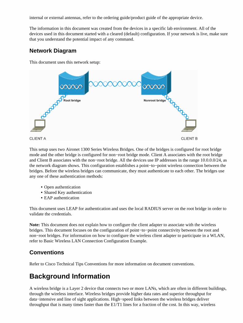
This document uses this network setup:
This setup uses two Aironet 1300 Series Wireless Bridges. One of the bridges is configured for root bridgemode and the other bridge is configured for non−root bridge mode. Client A associates with the root bridgeand Client B associates with the non−root bridge. All the devices use IP addresses in the range 10.0.0.0/24, asthe network diagram shows. This configuration establishes a point−to−point wireless connection between thebridges. Before the wireless bridges can communicate, they must authenticate to each other. The bridges useany one of these authentication methods:
Open authentication• Shared Key authentication• EAP authentication•
This document uses LEAP for authentication and uses the local RADIUS server on the root bridge in order tovalidate the credentials.
Note: This document does not explain how to configure the client adapter to associate with the wirelessbridges. This document focuses on the configuration of point−to−point connectivity between the root andnon−root bridges. For information on how to configure the wireless client adapter to participate in a WLAN,refer to Basic Wireless LAN Connection Configuration Example.
Conventions
Refer to Cisco Technical Tips Conventions for more information on document conventions.
Background Information
A wireless bridge is a Layer 2 device that connects two or more LANs, which are often in different buildings,through the wireless interface. Wireless bridges provide higher data rates and superior throughput fordata−intensive and line of sight applications. High−speed links between the wireless bridges deliverthroughput that is many times faster than the E1/T1 lines for a fraction of the cost. In this way, wireless
bridges eliminate the need for expensive leased lines and fiber−optic cables. You can use the wireless bridgesto connect these networks:
Difficult−to−wire sites• Noncontiguous floors• Temporary networks• Warehouses• Other networks•
The LANs that the wireless bridge connects can connect to the wireless bridge either through the wired LANor through the wireless interface. You can configure the wireless bridges for point−to−point andpoint−to−multipoint applications. This document configures the wireless bridges for point−to−pointconnectivity.
Configure the Root Bridge
GUI Configuration
This section presents the information to configure the wireless bridge as a root bridge.
Access the 1300 wireless bridge through the GUI and go to the Summary Status window.
Complete these steps:
Open a web browser and enter the IP address in the address line.
This example uses the IP address 10.0.0.1 for the root bridge. For information on how toassign an IP address to the wireless bridge, refer to the Obtaining and Assigning an IPAddress section of the document Configuring the Access Point/Bridge for the First Time.
a.
Press Tab in order to bypass the Username field and advance to the Password field.
The Enter Network Password window displays.
b.
Enter the case−sensitive password Cisco, and press Enter.
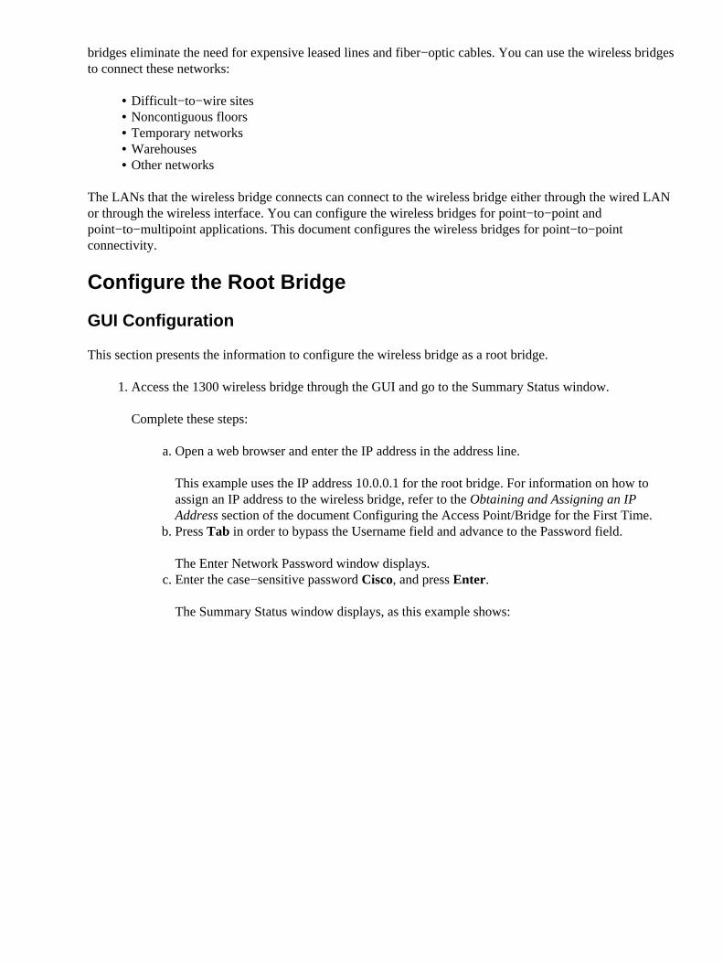
The Summary Status window displays, as this example shows:
c.
1.
Configure the radio interface.
Enable the radio interface and define it as a root bridge.
This radio interface acts as the wireless interface for the root bridge.
Note: The radio interface is disabled by default on 1300 wireless bridges that run Cisco IOSSoftware Release 12.3(7)JA.
Complete these steps:
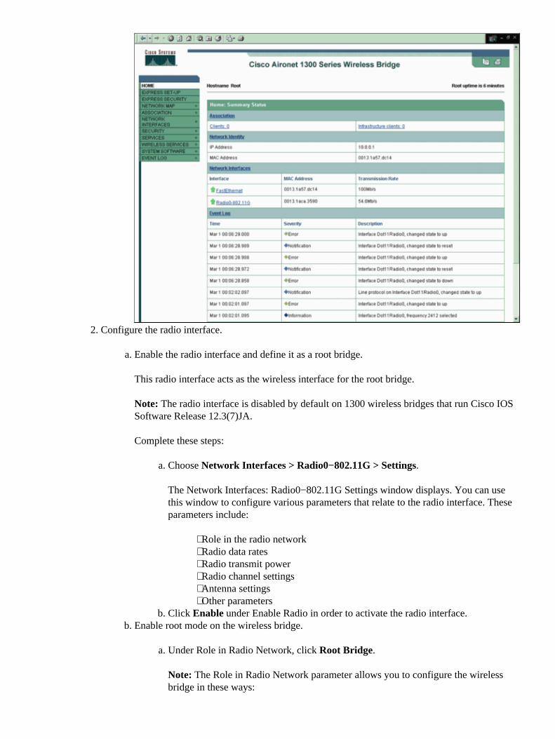
Choose Network Interfaces > Radio0−802.11G > Settings.
The Network Interfaces: Radio0−802.11G Settings window displays. You can usethis window to configure various parameters that relate to the radio interface. Theseparameters include:
Role in the radio network⋅ Radio data rates⋅ Radio transmit power⋅ Radio channel settings⋅ Antenna settings⋅ Other parameters⋅
a.
Click Enable under Enable Radio in order to activate the radio interface.b.
a.
Enable root mode on the wireless bridge.
Under Role in Radio Network, click Root Bridge.
Note: The Role in Radio Network parameter allows you to configure the wirelessbridge in these ways:
a.
b.
2.
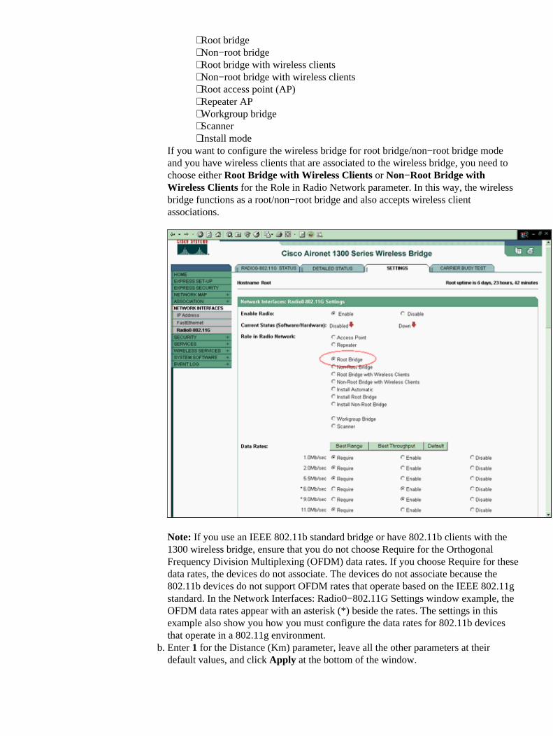
Root bridge⋅ Non−root bridge⋅ Root bridge with wireless clients⋅ Non−root bridge with wireless clients⋅ Root access point (AP)⋅ Repeater AP⋅ Workgroup bridge⋅ Scanner⋅ Install mode⋅
If you want to configure the wireless bridge for root bridge/non−root bridge modeand you have wireless clients that are associated to the wireless bridge, you need tochoose either Root Bridge with Wireless Clients or Non−Root Bridge withWireless Clients for the Role in Radio Network parameter. In this way, the wirelessbridge functions as a root/non−root bridge and also accepts wireless clientassociations.
Note: If you use an IEEE 802.11b standard bridge or have 802.11b clients with the1300 wireless bridge, ensure that you do not choose Require for the OrthogonalFrequency Division Multiplexing (OFDM) data rates. If you choose Require for thesedata rates, the devices do not associate. The devices do not associate because the802.11b devices do not support OFDM rates that operate based on the IEEE 802.11gstandard. In the Network Interfaces: Radio0−802.11G Settings window example, theOFDM data rates appear with an asterisk (*) beside the rates. The settings in thisexample also show you how you must configure the data rates for 802.11b devicesthat operate in a 802.11g environment.Enter 1 for the Distance (Km) parameter, leave all the other parameters at theirdefault values, and click Apply at the bottom of the window.
b.
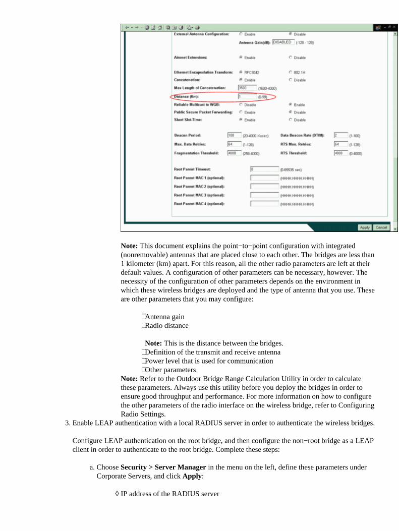
Note: This document explains the point−to−point configuration with integrated(nonremovable) antennas that are placed close to each other. The bridges are less than1 kilometer (km) apart. For this reason, all the other radio parameters are left at theirdefault values. A configuration of other parameters can be necessary, however. Thenecessity of the configuration of other parameters depends on the environment inwhich these wireless bridges are deployed and the type of antenna that you use. Theseare other parameters that you may configure:
Antenna gain⋅ Radio distance
Note: This is the distance between the bridges.
⋅
Definition of the transmit and receive antenna⋅ Power level that is used for communication⋅ Other parameters⋅
Note: Refer to the Outdoor Bridge Range Calculation Utility in order to calculatethese parameters. Always use this utility before you deploy the bridges in order toensure good throughput and performance. For more information on how to configurethe other parameters of the radio interface on the wireless bridge, refer to ConfiguringRadio Settings.
Enable LEAP authentication with a local RADIUS server in order to authenticate the wireless bridges.
Configure LEAP authentication on the root bridge, and then configure the non−root bridge as a LEAPclient in order to authenticate to the root bridge. Complete these steps:
Choose Security > Server Manager in the menu on the left, define these parameters underCorporate Servers, and click Apply:
IP address of the RADIUS server◊
a.
3.
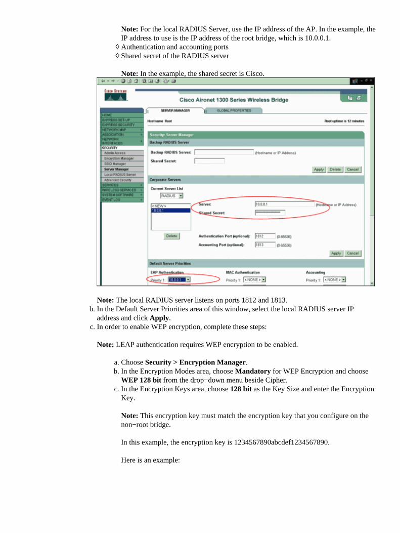
Note: For the local RADIUS Server, use the IP address of the AP. In the example, theIP address to use is the IP address of the root bridge, which is 10.0.0.1.Authentication and accounting ports◊ Shared secret of the RADIUS server
Note: In the example, the shared secret is Cisco.
◊
Note: The local RADIUS server listens on ports 1812 and 1813.In the Default Server Priorities area of this window, select the local RADIUS server IPaddress and click Apply.
b.
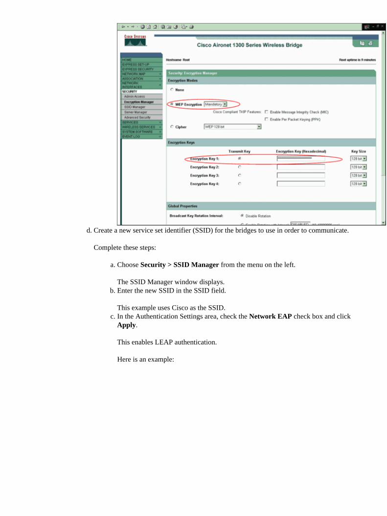
In order to enable WEP encryption, complete these steps:
Note: LEAP authentication requires WEP encryption to be enabled.
Choose Security > Encryption Manager.a. In the Encryption Modes area, choose Mandatory for WEP Encryption and chooseWEP 128 bit from the drop−down menu beside Cipher.
b.
In the Encryption Keys area, choose 128 bit as the Key Size and enter the EncryptionKey.
Note: This encryption key must match the encryption key that you configure on thenon−root bridge.
In this example, the encryption key is 1234567890abcdef1234567890.
Here is an example:
c.
c.
Create a new service set identifier (SSID) for the bridges to use in order to communicate.
Complete these steps:
Choose Security > SSID Manager from the menu on the left.
The SSID Manager window displays.
a.
Enter the new SSID in the SSID field.
This example uses Cisco as the SSID.
b.
In the Authentication Settings area, check the Network EAP check box and clickApply.
This enables LEAP authentication.
Here is an example:
c.
d.
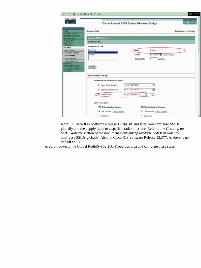
Note: In Cisco IOS Software Release 12.3(4)JA and later, you configure SSIDsglobally and then apply them to a specific radio interface. Refer to the Creating anSSID Globally section of the document Configuring Multiple SSIDs in order toconfigure SSIDs globally. Also, in Cisco IOS Software Release 12.3(7)JA, there is nodefault SSID.
Scroll down to the Global Radio0−802.11G Properties area and complete these steps:e.
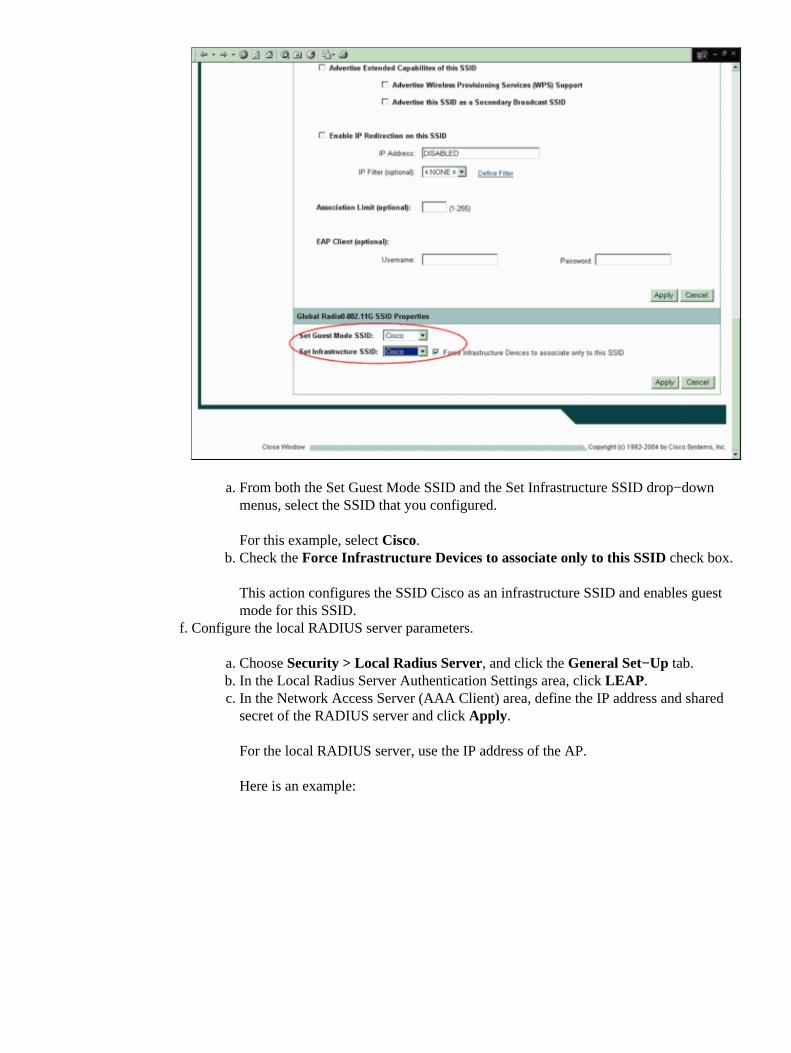
From both the Set Guest Mode SSID and the Set Infrastructure SSID drop−downmenus, select the SSID that you configured.
For this example, select Cisco.
a.
Check the Force Infrastructure Devices to associate only to this SSID check box.
This action configures the SSID Cisco as an infrastructure SSID and enables guestmode for this SSID.
b.
Configure the local RADIUS server parameters.
Choose Security > Local Radius Server, and click the General Set−Up tab.a. In the Local Radius Server Authentication Settings area, click LEAP.b. In the Network Access Server (AAA Client) area, define the IP address and sharedsecret of the RADIUS server and click Apply.
For the local RADIUS server, use the IP address of the AP.
Here is an example:
c.
f.
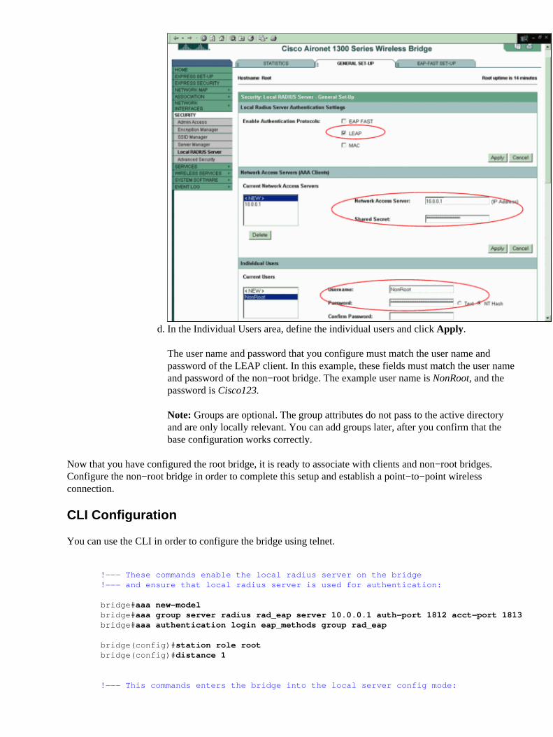
In the Individual Users area, define the individual users and click Apply.
The user name and password that you configure must match the user name andpassword of the LEAP client. In this example, these fields must match the user nameand password of the non−root bridge. The example user name is NonRoot, and thepassword is Cisco123.
Note: Groups are optional. The group attributes do not pass to the active directoryand are only locally relevant. You can add groups later, after you confirm that thebase configuration works correctly.
d.
Now that you have configured the root bridge, it is ready to associate with clients and non−root bridges.Configure the non−root bridge in order to complete this setup and establish a point−to−point wirelessconnection.
CLI Configuration
You can use the CLI in order to configure the bridge using telnet.
!−−− These commands enable the local radius server on the bridge!−−− and ensure that local radius server is used for authentication:
bridge#aaa new−modelbridge#aaa group server radius rad_eap server 10.0.0.1 auth−port 1812 acct−port 1813bridge#aaa authentication login eap_methods group rad_eap
bridge(config)#station role rootbridge(config)#distance 1
!−−− This commands enters the bridge into the local server config mode:
bridge(config)#radius−server local
!−−− By default LEAP, EAPFAST, and MAC authentications are!−−− supported. Using the no form for other 2 types ensures !−−− that LEAP is used for authentication.
bridge(config−radsrv)#no authentication eapfastbridge(config−radsrv)#no authentication mac
bridge(config)#interface dot11radio 0bridge(config−if)#ssid bridge
!−−− This command enables EAP authentication for the SSID.
bridge(config−if−ssid)#authentication network−eap rad_eap
!−−− This step is optional.!−−− This value seeds the initial key for use with broadcast!−−− [255.255.255.255] traffic. If more than one VLAN is!−−− used, then keys must be set for each VLAN.
bridge(config−if)#encryption vlan 1 key 1 size 128bit 12345678901234567890123456 transmit−key
!−−− This defines the policy for the use of Wired !−−− Equivalent Privacy (WEP). If more than one VLAN is used, !−−− the policy must be set to mandatory for each VLAN.
bridge(config−if)#encryption vlan 1 mode wep mandatory
bridge(config)#user cisco password cisco123
Configure the Nonroot Bridge
GUI Configuration
This section presents the information to configure the wireless bridge as a non−root bridge. The non−rootbridge authenticates as a LEAP client to the local RADIUS server on the root bridge.
Access the wireless bridge through the GUI and go to the Summary Status window.
Complete the instructions in Step 1 of the section Configure the Root Bridge in order to reach theSummary Status window.
Note: The non−root bridge is configured with IP address 10.0.0.2.
This window displays:
1.

Configure the SSID for communication.
Choose Security > SSID Manager from the menu on the left.
The SSID Manager window appears.
a.
Enter the same SSID that you configured on the root bridge in the SSID field.b. In the Authentication Settings area, check the Network EAP check box.c.
2.
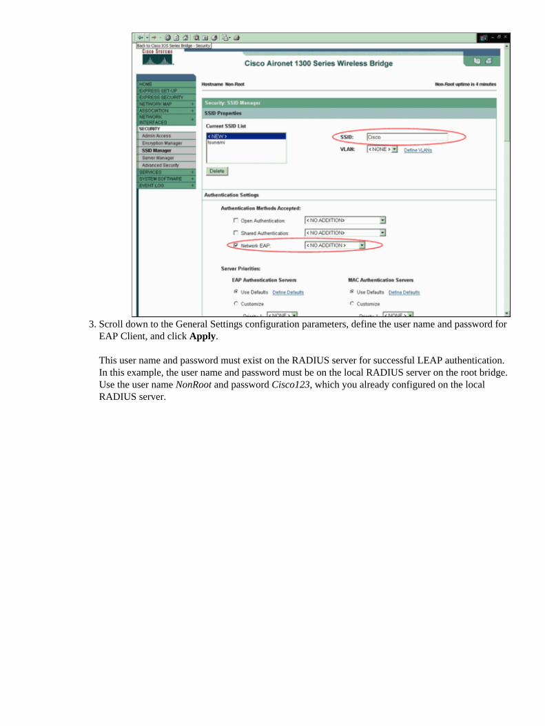
Scroll down to the General Settings configuration parameters, define the user name and password forEAP Client, and click Apply.
This user name and password must exist on the RADIUS server for successful LEAP authentication.In this example, the user name and password must be on the local RADIUS server on the root bridge.Use the user name NonRoot and password Cisco123, which you already configured on the localRADIUS server.
3.
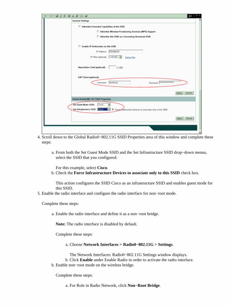
Scroll down to the Global Radio0−802.11G SSID Properties area of this window and complete thesesteps:
From both the Set Guest Mode SSID and the Set Infrastructure SSID drop−down menus,select the SSID that you configured.
For this example, select Cisco.
a.
Check the Force Infrastructure Devices to associate only to this SSID check box.
This action configures the SSID Cisco as an infrastructure SSID and enables guest mode forthis SSID.
b.
4.
Enable the radio interface and configure the radio interface for non−root mode.
Complete these steps:
Enable the radio interface and define it as a non−root bridge.
Note: The radio interface is disabled by default.
Complete these steps:
Choose Network Interfaces > Radio0−802.11G > Settings.
The Network Interfaces: Radio0−802.11G Settings window displays.
a.
Click Enable under Enable Radio in order to activate the radio interface.b.
a.
Enable non−root mode on the wireless bridge.
Complete these steps:
For Role in Radio Network, click Non−Root Bridge.a.
b.
5.
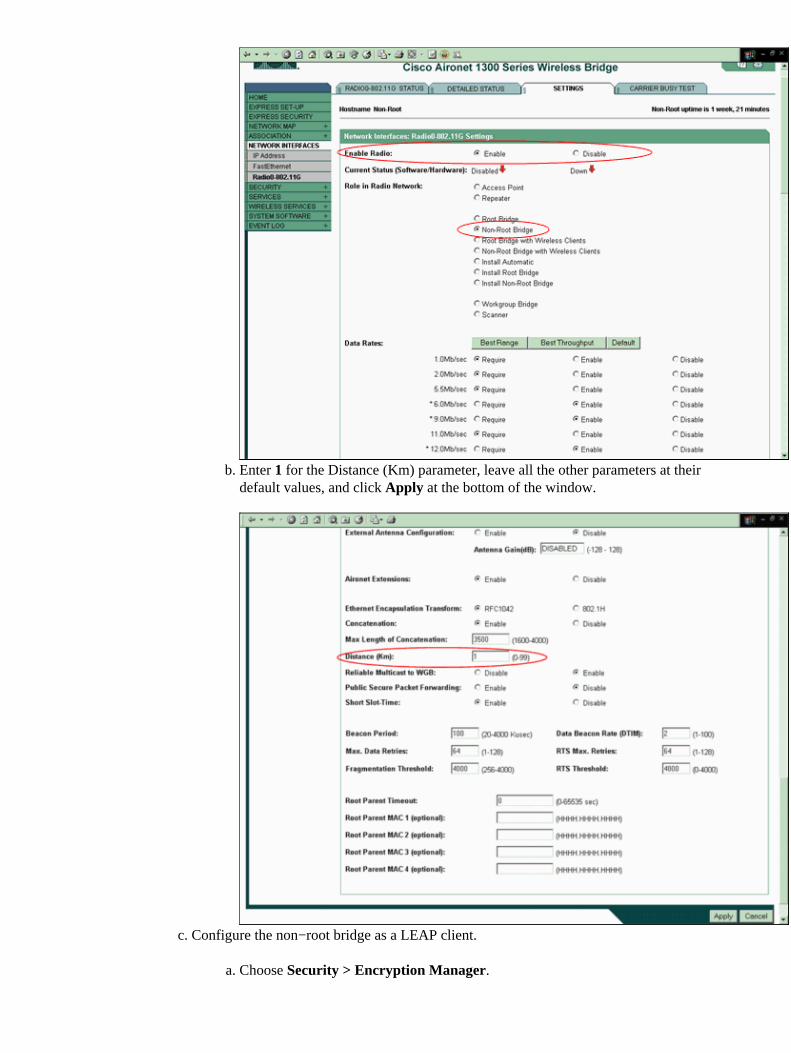
Enter 1 for the Distance (Km) parameter, leave all the other parameters at theirdefault values, and click Apply at the bottom of the window.
b.
Configure the non−root bridge as a LEAP client.
Choose Security > Encryption Manager.a.
c.
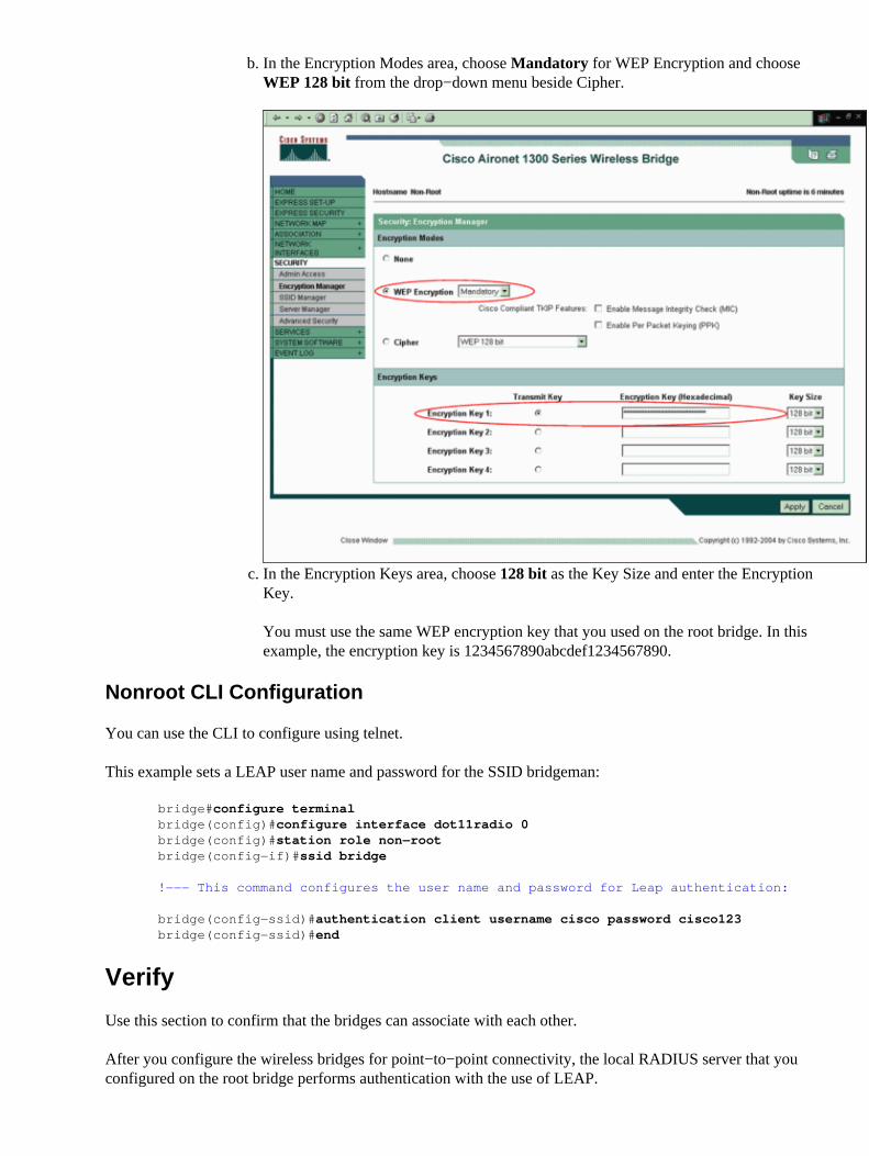
In the Encryption Modes area, choose Mandatory for WEP Encryption and chooseWEP 128 bit from the drop−down menu beside Cipher.
b.
In the Encryption Keys area, choose 128 bit as the Key Size and enter the EncryptionKey.
You must use the same WEP encryption key that you used on the root bridge. In thisexample, the encryption key is 1234567890abcdef1234567890.
c.
Nonroot CLI Configuration
You can use the CLI to configure using telnet.
This example sets a LEAP user name and password for the SSID bridgeman:
bridge#configure terminalbridge(config)#configure interface dot11radio 0bridge(config)#station role non−rootbridge(config−if)#ssid bridge
!−−− This command configures the user name and password for Leap authentication:
bridge(config−ssid)#authentication client username cisco password cisco123bridge(config−ssid)#end
Verify
Use this section to confirm that the bridges can associate with each other.
After you configure the wireless bridges for point−to−point connectivity, the local RADIUS server that youconfigured on the root bridge performs authentication with the use of LEAP.
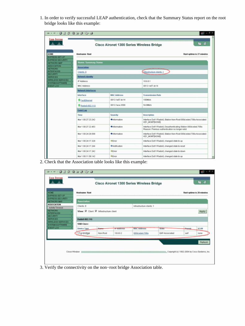
In order to verify successful LEAP authentication, check that the Summary Status report on the rootbridge looks like this example:
1.
Check that the Association table looks like this example:2.
Verify the connectivity on the non−root bridge Association table.3.
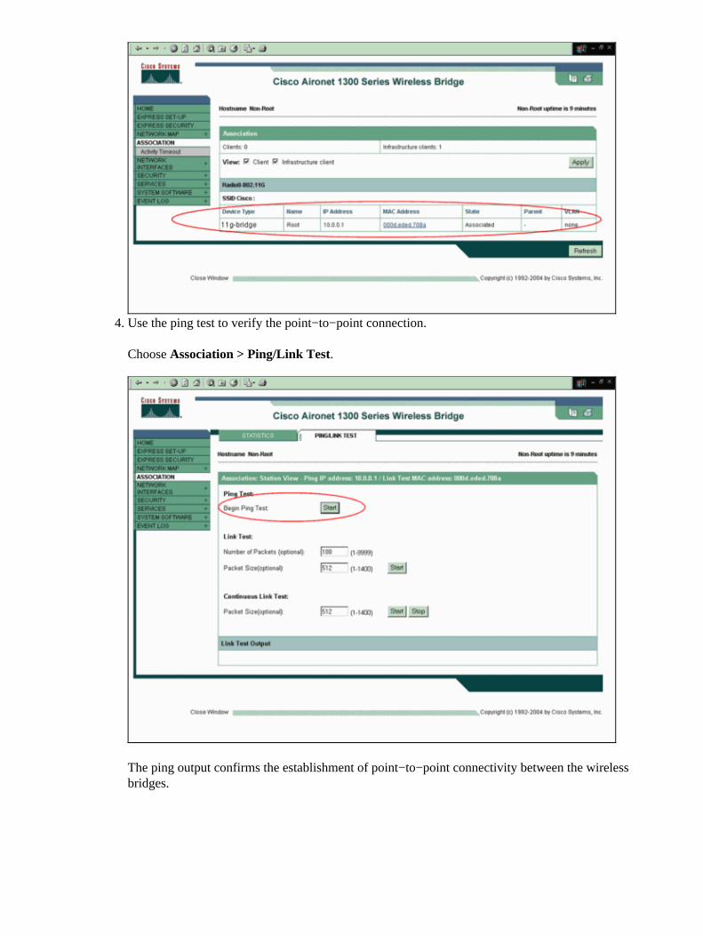
Use the ping test to verify the point−to−point connection.
Choose Association > Ping/Link Test.
The ping output confirms the establishment of point−to−point connectivity between the wirelessbridges.
4.
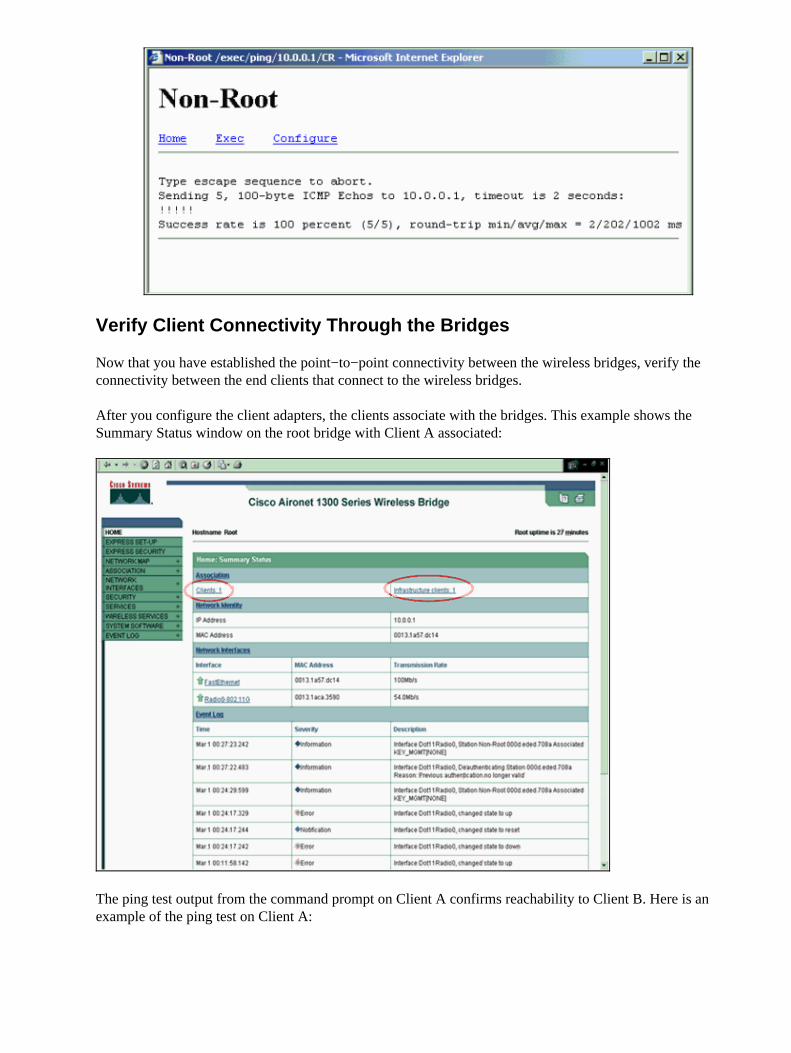
Verify Client Connectivity Through the Bridges
Now that you have established the point−to−point connectivity between the wireless bridges, verify theconnectivity between the end clients that connect to the wireless bridges.
After you configure the client adapters, the clients associate with the bridges. This example shows theSummary Status window on the root bridge with Client A associated:
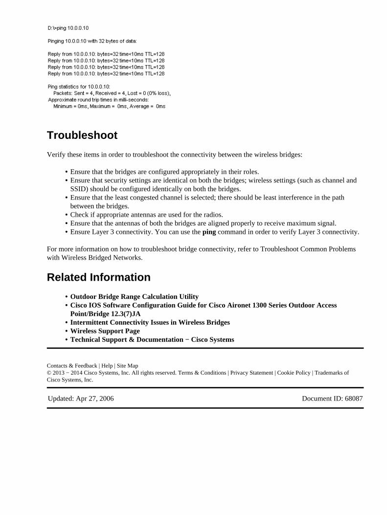
The ping test output from the command prompt on Client A confirms reachability to Client B. Here is anexample of the ping test on Client A:
Troubleshoot
Verify these items in order to troubleshoot the connectivity between the wireless bridges:
Ensure that the bridges are configured appropriately in their roles.• Ensure that security settings are identical on both the bridges; wireless settings (such as channel andSSID) should be configured identically on both the bridges.
•
Ensure that the least congested channel is selected; there should be least interference in the pathbetween the bridges.
•
Check if appropriate antennas are used for the radios.• Ensure that the antennas of both the bridges are aligned properly to receive maximum signal.• Ensure Layer 3 connectivity. You can use the ping command in order to verify Layer 3 connectivity.•
For more information on how to troubleshoot bridge connectivity, refer to Troubleshoot Common Problemswith Wireless Bridged Networks.
Related Information
Outdoor Bridge Range Calculation Utility• Cisco IOS Software Configuration Guide for Cisco Aironet 1300 Series Outdoor AccessPoint/Bridge 12.3(7)JA
•
Intermittent Connectivity Issues in Wireless Bridges• Wireless Support Page• Technical Support & Documentation − Cisco Systems•
Contacts & Feedback | Help | Site Map© 2013 − 2014 Cisco Systems, Inc. All rights reserved. Terms & Conditions | Privacy Statement | Cookie Policy | Trademarks ofCisco Systems, Inc.
Updated: Apr 27, 2006 Document ID: 68087