Embed Size (px)
Citation preview

UPTEC F 20037
Examensarbete 30 hpJuni 2020
Wireless control of industrial robot
Johan Paulsson
Masterprogrammet i fysikMaster Programme in Physics

Teknisk- naturvetenskaplig fakultet UTH-enheten Besöksadress: Ångströmlaboratoriet Lägerhyddsvägen 1 Hus 4, Plan 0 Postadress: Box 536 751 21 Uppsala Telefon: 018 – 471 30 03 Telefax: 018 – 471 30 00 Hemsida: http://www.teknat.uu.se/student
Abstract
Wireless control of industrial robot
Johan Paulsson
The purpose of this project was to investigate if it is possible to have local wireless control of an industrial robot. This was achieved by first doing a diversity of research. Based on the research, the project was conceptualized and a real-life product was developed showcasing the functionality. The standard robot set up as of today consists of three main parts: A robot, a control unit and a handheld controller device, called Teach Pendant. All of these parts are connected with long aggravating cables. The cables cause inconvenience and can in some cases introduce unnecessary risks in the factory. Can this hardware be removed, and an overall more convenient use case be developed?
The product was developed by programming an application on a Windows tablet. Further, a Bluetooth Low Energy server was created to handle the communication between the tablet and the robot control unit. The final product consisted of a tablet, a single-board computer, a robot and a control unit. The tablet is what replaces the Teach Pendant as a handheld device. The tablet is connected to the single-board computer via Bluetooth. The single-board computer acts as a Bluetooth server and sends out advertisements for the tablet to detect. When the tablet detects a nearby robot it can then connect to it and send start and stop commands. The server then forwards it to the control unit which finally sends the data to the robot control unit to execute. The project shows that it is possible to develop wireless robot control. It showcases a potential solution on how one could set it up. However, the final product developed had a simple functionality compared to the wired Teach Pendant. To manage the same capacity as the wired Teach Pendent, further development is required.
Tryckt av: UppsalaISSN: 1401-5757, UPTEC F20037Examinator: Tomas NybergÄmnesgranskare: Jörgen OlssonHandledare: Jonas Brönmark

Popularvetenskaplig sammanfattning
Inom industrin idag anvands robotar for att forenkla och effektivisera produktion.Robotlosningen idag inkluderar en handkontroll som ar ansluten via en kabel fordataoverforing och stromforsorjning. En stor forbattringsmojlighet for att gora robotarnasakrare och effektivare ar att ta bort kabeln. Ar detta mojligt?
I dagens samhalle styrs manga av vara tekniska produkter tradlost. Detta pavisar att tekniken for att avengora andra produkter tradlosa existerar. Trots detta, anvands inte samma teknik for att styraindustrirobotar.
Idag styrs en industrirobot lokalt av en handkontroll som kallas Teach Pendent, vilken i sin tur ar koppladtill roboten via en kabel. For att anvandaren ska kunna manovrera sig kring roboten behover kabeln avenvara lang. Detta resulterar i en sakerhetsrisk da alla foremal pa marken, dar en manniska vistas, okarrisken for att ramla.
I detta examensarbete undersoktes mojligheten att gora Teach Pendent-enheten tradlos. For attastadkomma detta gjordes forst en undersokning bestaende av intervjuer, litteraturstudie, studiebesok ochenkatundersokning inom foretaget. Nasta steg var att visualisera en produkt utifran undersokningen somgjorts. Produkten konceptualiserades och en vidare plan utvecklades for att mojliggora enproduktutveckling.
Metoden som anvandes var att programmera en applikation pa en lasplatta for att vidare kunnakommunicera med och styra roboten. Det tradlosa kommunikationsverktyget som anvandes var Bluetooth.
Det slutgiltiga resultatet ar enhet som tradlost kan kommunicera med roboten. Anvandningen av dentradlosa lasplattan mojliggjorde start och stopp av roboten. Losningen som togs fram var enkel i jamforelsemed den vanliga Teach Pendant-enheten, men visar pa en mojlig vidareutveckling.

Acknowledgments
Firstly, I would like to thank my supervisor at ABB Jonas Bronmark for his time invested in support andguidance. Also i would like to thank Martin Nordvall for his support of the project. Further I would like tothank the department at ABB Robotics for their welcoming and support throughout the thesis.
Secondly, I want to thank my thesis supervisor at the university, Jorgen Olsson for support in keeping meon track and providing feedback during the thesis.

Contents
1 Introduction 1
2 Background 22.1 Collaboration . . . . . . . . . . . . . . . . . . . . . . . . . . . . . . . . . . . . . . . . . . . . . 22.2 Purpose and Goals . . . . . . . . . . . . . . . . . . . . . . . . . . . . . . . . . . . . . . . . . . 22.3 Overview of The Project . . . . . . . . . . . . . . . . . . . . . . . . . . . . . . . . . . . . . . . 22.4 Delimitations . . . . . . . . . . . . . . . . . . . . . . . . . . . . . . . . . . . . . . . . . . . . . 2
3 Theory 43.1 Robot Setup . . . . . . . . . . . . . . . . . . . . . . . . . . . . . . . . . . . . . . . . . . . . . 4
3.1.1 The Robot . . . . . . . . . . . . . . . . . . . . . . . . . . . . . . . . . . . . . . . . . . 43.1.2 Control Unit . . . . . . . . . . . . . . . . . . . . . . . . . . . . . . . . . . . . . . . . . 53.1.3 Teach Pendant Unit . . . . . . . . . . . . . . . . . . . . . . . . . . . . . . . . . . . . . 6
3.2 Additional Hardware . . . . . . . . . . . . . . . . . . . . . . . . . . . . . . . . . . . . . . . . . 73.2.1 Tablet . . . . . . . . . . . . . . . . . . . . . . . . . . . . . . . . . . . . . . . . . . . . . 7
3.3 Wireless requirements . . . . . . . . . . . . . . . . . . . . . . . . . . . . . . . . . . . . . . . . 93.4 Ultra Wide Band . . . . . . . . . . . . . . . . . . . . . . . . . . . . . . . . . . . . . . . . . . . 93.5 5G . . . . . . . . . . . . . . . . . . . . . . . . . . . . . . . . . . . . . . . . . . . . . . . . . . . 93.6 Bluetooth . . . . . . . . . . . . . . . . . . . . . . . . . . . . . . . . . . . . . . . . . . . . . . . 10
3.6.1 Advertising Package . . . . . . . . . . . . . . . . . . . . . . . . . . . . . . . . . . . . . 10
4 Method 124.1 Research . . . . . . . . . . . . . . . . . . . . . . . . . . . . . . . . . . . . . . . . . . . . . . . . 12
4.1.1 Internal Interviews . . . . . . . . . . . . . . . . . . . . . . . . . . . . . . . . . . . . . . 124.1.2 Survey . . . . . . . . . . . . . . . . . . . . . . . . . . . . . . . . . . . . . . . . . . . . . 124.1.3 Customer Visits . . . . . . . . . . . . . . . . . . . . . . . . . . . . . . . . . . . . . . . 12
4.2 Choice of Implementation . . . . . . . . . . . . . . . . . . . . . . . . . . . . . . . . . . . . . . 134.3 Implementation . . . . . . . . . . . . . . . . . . . . . . . . . . . . . . . . . . . . . . . . . . . . 13
4.3.1 Implementation Workflow . . . . . . . . . . . . . . . . . . . . . . . . . . . . . . . . . . 134.3.2 Overview . . . . . . . . . . . . . . . . . . . . . . . . . . . . . . . . . . . . . . . . . . . 144.3.3 Tablet . . . . . . . . . . . . . . . . . . . . . . . . . . . . . . . . . . . . . . . . . . . . . 144.3.4 Server . . . . . . . . . . . . . . . . . . . . . . . . . . . . . . . . . . . . . . . . . . . . . 15
4.4 Test at ABB . . . . . . . . . . . . . . . . . . . . . . . . . . . . . . . . . . . . . . . . . . . . . 18
5 Result 205.1 Internal interviews . . . . . . . . . . . . . . . . . . . . . . . . . . . . . . . . . . . . . . . . . . 205.2 Customer Visits . . . . . . . . . . . . . . . . . . . . . . . . . . . . . . . . . . . . . . . . . . . . 20
5.2.1 ICA . . . . . . . . . . . . . . . . . . . . . . . . . . . . . . . . . . . . . . . . . . . . . . 205.2.2 Volvo . . . . . . . . . . . . . . . . . . . . . . . . . . . . . . . . . . . . . . . . . . . . . 215.2.3 Sejfo . . . . . . . . . . . . . . . . . . . . . . . . . . . . . . . . . . . . . . . . . . . . . . 21
3
5.3 Survey . . . . . . . . . . . . . . . . . . . . . . . . . . . . . . . . . . . . . . . . . . . . . . . . . 215.4 Research Summary . . . . . . . . . . . . . . . . . . . . . . . . . . . . . . . . . . . . . . . . . . 215.5 Product . . . . . . . . . . . . . . . . . . . . . . . . . . . . . . . . . . . . . . . . . . . . . . . . 21
5.5.1 Functionality . . . . . . . . . . . . . . . . . . . . . . . . . . . . . . . . . . . . . . . . . 215.5.2 Interface . . . . . . . . . . . . . . . . . . . . . . . . . . . . . . . . . . . . . . . . . . . . 23
5.6 Test at ABB . . . . . . . . . . . . . . . . . . . . . . . . . . . . . . . . . . . . . . . . . . . . . 23
6 Discussion 246.1 Overall Product Performance . . . . . . . . . . . . . . . . . . . . . . . . . . . . . . . . . . . . 246.2 Hardware . . . . . . . . . . . . . . . . . . . . . . . . . . . . . . . . . . . . . . . . . . . . . . . 246.3 Software . . . . . . . . . . . . . . . . . . . . . . . . . . . . . . . . . . . . . . . . . . . . . . . . 24
6.3.1 Challenges . . . . . . . . . . . . . . . . . . . . . . . . . . . . . . . . . . . . . . . . . . 246.3.2 Final result . . . . . . . . . . . . . . . . . . . . . . . . . . . . . . . . . . . . . . . . . . 25
7 Conclusions 267.1 Further developments . . . . . . . . . . . . . . . . . . . . . . . . . . . . . . . . . . . . . . . . 26

1. Introduction
With the evolution of the Internet of Things (IoT), wireless technology and its capabilities have drasticallyimproved in many areas, such as stability and latency. In addition, the overall cost of the wireless setuphas decreased. As a result, everything from cars to refrigerators can be an IoT device. One market whichstill has not adopted the new wireless standard is industrial robots, where most robots still use a wiredhandheld device for local control.
Manufacturers operating robots need to fulfill strict requirements. The cells in which the robots operatemust be clean, safe and efficient. This is to minimize the risk of an accident which could cause harm to bothhumans and the production line. When the robot’s technology advances, the requirements increase evenfurther, and more robots are starting to work together in even tighter spaces. This leads to a need to removeunnecessary hardware to maintain a clean cell. Therefore, it is fascinating to turn the local handheld deviceinto a modern wireless control unit.
1

2. Background
2.1 Collaboration
This thesis work was performed in collaboration with ABB Robotics. ABB Robotics is a division in ABB,which is world-leading in robot development.
This thesis was partly made together with another student at Uppsala University, focusing on the area ofUser Experience. The goal of her work was to design the interface of the application, whereas this workfocuses on the programming of the implementation. Although the collaboration continued throughout theproject, all work presented in this report relates only to the work of the author.
2.2 Purpose and Goals
The main purpose of this project is to investigate if it is possible to control an industrial robot without theuse of wires. Further, challenges and limitations that occur when removing a wired connection will beinvestigated. The final goal is to start developing a prototype showing the capabilities of a wireless robot.
2.3 Overview of The Project
Since wireless industrial robot control is a new feature, the end product is hard to visualize. Furthermore,there is no specific previous work to take advantage of, especially from a technical point of view. Therefore,the first part of this project was to research and try to define how the wireless control should be appliedand to find what features hardware, and software the end customers of the product requirements.
When the research was established and analyzed, it was supposed to be conceptualized into a workingprototype. The prototype was then to be programmed and connected to an already setup robot configuration.In the early stage of the project, it was established that the prototype will have limited functionality butcould showcase a solution that can be further developed. Finally, problems that occurred with real wirelesscommunication were discussed and solutions were briefly discussed.
2.4 Delimitations
To transform a wired industrial device to wireless is a complex project, especially since it has to follow thestandards of a major multinational company. Requirements cover areas like industrial regulations, acost-effective solution, and high demands on reliability. Therefore, this project is seen as a startingplatform for further development.
2

This project will work with ABB’s new robot controller OmniCore. As of today, this controller only supportsa few of ABB’s robotic lineups. However, OmniCore will be able to support more robots in the future.For the wireless communication of the product, there exists a lot of potential working solutions. Because oflimitations in the industry, such as cost, hardware implementation, and support, Bluetooth was selected forfurther development. Also, investigations on Ultra-Wide Band and 5G were conducted to present solutionsto problems that arose during the project.
3

3. Theory
3.1 Robot Setup
An industrial robot is defined as a robot that is automatically controlled, re-programmable, and includesthree or more axes [1]. The industrial robot has a variety of different compositions to handle the divergenttasks of the modern industry. The smaller robots manipulate small weights of less than 5 kg. The biggerones can handle multiples of hundreds of kilos.
The current robot setup that is used today consists of three major parts: the robot, the control unit, andthe Teach Pendant Unit (TPU). The robot is connected to the control unit via wires for power and data.The control unit is similarly connected to the TPU, but with one long cable. An example of the currentsetup can be seen in figure 3.1.[2]
Figure 3.1: Example of a robot setup as of today
3.1.1 The Robot
The robot is the mechanical part of the setup. It contains all the motors, moving joints, and the endeffector. The configuration of the robot differs depending on the task and environment. The main types ofrobot configurations are Articulated, Cartesian, Cylindrical, Polar, SCARA, and Delta. In this project,only Articulated robots were used.
The Articulated robot’s design features rotary joints and links. The final movement of the robot is definedby each angle of the joints. Depending on how many joints the robot has, the potential of the complexityof its movement increases. This is due to each angle introduces one more degree of freedom to the robot.The common industry robot usually has six axes. An example of an Articulated robot arm can be seen infigure 3.2. [3]
4

Figure 3.2: Example of an industrial robot arm, the IRB-4400 from ABB [4]
3.1.2 Control Unit
The control unit of a robot, usually called the controller, reads input,and transforms it to be the output ofa specific robot. The input of the controller can either be generated by human input or by programexecution. The controller then reads the input and transforms it into an output for the robot to execute.One example would be a move instruction of an articulated robot arm from program execution. Thecontroller receives information about where in space the robot is supposed to move and transforms it intoangles of each joint. Lastly, the instruction is sent to the robot to execute.[5].
The controller is usually a separate device from the robot in the form of a cabinet. Further, the controlleris connected by power- and data wires from the cabinet to the robot. This is required because of the lowlatency needed for the robot to operate. As of today, a robot controller is not limited to controlling onerobot. An example is ABB’s current generation of controllers, which can handle up to four robots at thesame time. [6]
OmniCore
The OmniCore is ABB’s latest robot controller, seen in figure 3.3, and it is seen as a compact and moderncontroller. The OmniCore has several I/O ports, shown in figure 3.4, where the different ports have differentfunctionality. The MGMT (management) port is used for quick access to the robot and the port auto-configures an IP address to the connected device. Therefore, the connected device becomes ”plug and play”,which means that a user only needs to connect the device for it to start working. [7]
Figure 3.3: Overview of ABB’s OmniController [7]
5

Figure 3.4: Backside of ABB’s OmniController displaying I/O ports [7]
3.1.3 Teach Pendant Unit
The Teach Pendant Unit (TPU), is a handheld device for local remote robot control. The looks andfunctionality of a TPU vary between different companies. The design of ABB’s latest TPU can be seen infigure 3.5. The functionality and features vary between companies as well. However, all hold thefunctionality to operate the robot. These include programming the robot task, jogging the robot, andstarting and stopping. The TPU is connected to the controller via a long troublesome wire. This is topower the TPU and send data back and forth to the controller.
One important feature of the TPU is the emergency stop function. The TPU usually has a big red buttonthat should stop all robots in line of sight. The implementation of what the emergency button should stopis up to the integrator. From a robot developer’s point of view, it should only stop the connected robot. [2]
The TPU is not needed for the setup of the robot to run. Programming can be done offline beforehand andoperation can be done via computers over a programmable logic controller. However, the TPU has manyimportant areas of use. For example fine-tuning the programming, local start and stop and quick errorfixes.
6

Figure 3.5: ABB new Teach Pendant (TPU) to their new controller[7]
3.2 Additional Hardware
3.2.1 Tablet
The tablet used in this project is a Lenovo ThinkPad 10, which can be seen in figure 3.6. The tablet runsWindows 10 Pro. The specifications of the device are:
• Processor: Intel Atom z3795 @1.6GHz
• Ram: 2GB
• Bluetooth: Bluetooth 4.0 with BLE
7

Figure 3.6: Lenovo ThinkPad 10 tablet[8]
Raspberry Pi
The Raspberry pi is a single-board computer with up to 4 GB of ram, which can be seen in figure 3.7. TheRaspberry PI in this project ran the Raspian Operating System based on Linuxs. The specifications of theRaspberry Pi are:
• Processor: Broadcom BCM2711, Quad core Cortex-A72 (ARM v8) 64-bit SoC @ 1.5GHz
• Ram: 4GB
• Bluetooth: Bluetooth 5.0 with BLE
Figure 3.7: Raspberry PI 4, 4GB[9]
8

3.3 Wireless requirements
Wireless communication is defined as data being sent without the need of a physical hardware connection.The procedure to manage communication differs between technologies. The most common way is to senddata through radio signals. Radio waves transfer signals by modeling electromagnetic waves withfrequencies lower than the frequency of visible light. The waves travel with oscillating electromagneticfields through both air and vacuum. Information is delivered by changing properties of the wave, such asamplitude, frequency or phase. Two other technologies that do not utilize radio signals are induction andoptical-free space. Because of their physical constraints, none of them are viable for this project. Inductionbecause of its limited range and optical-free space for its requirement of line of sight.
The requirements for the wireless communication of this project is:
• Easy to implement
• Fast and responsive
• Safe an reliable
• Range > 10 m
• No need for line of sight
3.4 Ultra Wide Band
Ultra-wideband (UWB) is a short-range communication protocol that uses radio pulses to communicate. Incontrast to alternative radio signal technologies, such as Bluetooth and Wi-fi, it operates at higherfrequencies (3.1 - 10.6 GHz). As a result, the interference compared to other prevalent technologies in theFHSS band is reduced. As the name ultra-wideband implies, the protocol sends data over a wide frequencyspectrum. To be classified as ultra-wideband, a minimum bandwidth of 500 MHz has to be utilized. Sinceit uses higher frequencies, it more prone to disturbances due to loss of line of sight. Although, line of sightis not required to operate.
The technology has been around for several years but has seen limited consumer applications. It has beenimplemented in military applications as a precise locating and tracking protocol. Because of its limited use,the advancement of the technology for other use cases are finite. However, in recent years it has seen anupswing and is implemented in some consumer smartphones. Thus, the technology should be reduced inprice in the upcoming years.
To implement ultra-wideband with its location tracking potential, at least three hardware anchor nodes andone tag are must be implemented. The tag can send out pulses and measure the time it takes to eachindividual anchor node. With triangulation, the local position is then acquired. [10]
3.5 5G
5G, or generation five of cellular network, is the latest iteration of wireless cellular network. It is still in itsstart-up phase and a lot of research and development is still ongoing. 5G, on the contrary to previousgenerations of the cellular network, was developed to accommodate for the requirements of the industry.Therefore, the technology has not only greatly improved data bandwidth, but also latency and accuracy.Both accuracy and latency are of extreme importance in industrial applications since a lost or delayed datapackage could result in serious harm to both people and production. [11]
9

To setup 5G as of today, one would need a local cellular router inside the facility. In addition, all connecteddevices need a capable 5G modem. This implies a high start-up cost, though once set up, all other devicescould use the same router.
3.6 Bluetooth
Most of the wireless communication protocols for close-range applications use Bluetooth. The greater partof all consumer devices meets the requirement to handle a Bluetooth connection. In addition, Bluetoothhas many industrial implementations. Because of its extent and variety of different areas of use, theprotocol has become low-cost to set up and is simple to adapt to new scenarios.
Bluetooth operates in the highly contested unlicensed ISM band at 2.4 GHz. This introduces a problem ofinterference from other FHSS carriers. To counteract the interference, Bluetooth has implementedfrequency hopping. This is generally accomplished by frequency hopping 1 MHz at the time until a freeband is found. When a free band is found, a physical channel is established from a master device to theslave device. The master device is then responsible to handle the continuance of the channel. The channelallows quick bidirectional data transfer between the connected devices.
In 2010, Bluetooth Sig group announced a new technology, Bluetooth Low Energy (BLE). This wasintroduced to support devices with battery constraints. This helps battery-driven devices to withstandlonger periods of time without the need to charge. In 2016, Bluetooth introduced Bluetooth 5.0, whichfurther improved BLE, with increased range, data transfer speed and stability. [12]
3.6.1 Advertising Package
Bluetooth advertisement package is a small data package used by Bluetooth devices to broadcastthemselves. The advertisement holds information of the Bluetooth device and how it should be interpreted.This includes if the device is connectable and if so, how to establish a connection. However, parts of theadvertisement can be altered to serve different purposes.
When setting up a Bluetooth advertisement, the first thing to do is set the standard information. Thesesettings are structured according to the Bluetooth core specifications. The needed settings are:
• Advertising Interval Min
• Advertising Interval Max
• Advertising Type
• Own Address Type
• Peer Address Type
• Peer Address
• Advertising Channel Map
• Advertising Filter Policy
Each value has a standard value and in most cases, the value can be left as standard. To see more optionsfor each individual setting, see Bluetooth Core Specification. [13]
10

In addition to the standard information included in the package, custom data can be attached. To enablethis, two parameters haves to be set, Advertising Data Length and Advertising Data. [14]
The structure of the custom data can be seen in figure 3.8. The total size of the complete custom data is 31bytes. In this data, any number of AD structures can fit, as long as their total size is less than 31 bytes. Thesignificant part of the custom data is composed of the AD structures. The rest is filled with non-significantzeroes.
Figure 3.8: Structure of the Advertisement data[15]
Each AD structure has to reflect the instructions mentioned in the Bluetooth core. The first byte containsthe total length of the AD structure. The following bytes are the data of the structure. In the data bytes,the first byte describes the type of the AD structure. The structure is described by a predefinedhexadecimal number set by the Bluetooth Sig Group. The rest of the data is what holds the actualinformation.
The most relevant AD structure for this project is Complete Local Name and Manufacturer Data. The ADstructure Complete Local Name accomplish what its name implies, including the local name of the device.
The AD structure Manufacturer Data represent data used for manufactures. It follows the same structureas regular AD structure. Furthermore, the first 2 bytes of the data section are reserved for a manufacturerID. Bluetooth has a predefined list of company identifiers available on their website. [14] This letsBluetooth devices filter out devices from a specific manufacturer and ignore the rest. This also ignoresstandard consumer Bluetooth devices. The rest of the Manufacture data structure is custom data.
11

4. Method
4.1 Research
Since the end product was not clearly defined, the first step was to research how a wireless TPU would fitin today’s robot market and then to identify how it could be beneficial for ABB and ABB’s customers. Thequestion: “is it a relevant product to develop?” is to be answered. Furthermore, when the wireless TPU iscreated, it needs to be determined what challenges might occur and how to prevent them.
To get a good overview of the situation, different kinds of research methods were done. These methods were:
• Internal interviews
• Survey
• Paper research
• Customer visit
4.1.1 Internal Interviews
Internal interviews were done to understand the thoughts of people working with the current wired TPU,discussing what problems they have faced that should be avoided in new product development. Any risksthat could be introduced with a wireless connection were also discussed. The questions asked to interviewpeople was a general question regarding their work with the TPU and how it would transfer to the wirelesssolution.
To get a good overview, the people that where interviewed had different areas of expertise: Security, salesand general technology.
4.1.2 Survey
The Survey was performed to get broad input on moving to a wireless TPU. It was sent out within ABBboth in Sweden and internationally. Thereby, the diversity of the consultation increased. This also led to abetter overall statistical overview of expected problems related to wireless TPU.
The survey consisted of ten different questions. These included questions to find out where people werestationed, in what department they are working and how experienced they are with the TPU. In addition,questions to find out the biggest concerns regarding the wireless connection where asked.
4.1.3 Customer Visits
The customer visits were done to get direct feedback from non-developers of the TeachPendant, who use theTeachPendant in their daily work. The amount of use differs substantially for different customers. This isrelevant since the TPU should be a universal device which is usable for all industries.
12

4.2 Choice of Implementation
The concept of the final product was conceptualized based on the research. However, because of the timeconstraints of the project, only a first iteration of the prototype could be developed. As a result, the finalproduct implementation has less functionality compared to the existing TPU.
The TPU, which is the handheld device, will be replaced by a Tablet. The tablet will run Windows 10 andcommunicate with a single-board computer via the tablets built-in Bluetooth modem. The tablet used inthis The single-board computer will then communicate to the controller via https requests.
4.3 Implementation
4.3.1 Implementation Workflow
The implementation of the technical part was performed and developed through trial and error, attemptswere created or continued until successful. To develop and manage the code for the final product, theoverall setup was divided into smaller problems. Each problem described a specific function of thecomposition. The problems were handled individually and when the performance was satisfactory for all ofthem, the final product could be completed.
The first function to conduct was communication with the robot controller. The real controller was notavailable for early development because of the damage it could do to real a system. ABB has thereforecreated virtual controllers, which runs the same software as a real robot controller. The only differencebeing the virtual controller running on the computer’s hardware and is connected to a virtual robot. As aresult, the virtual robot setup allows for risk-free product development. The goal of this part was tocommunicate to a controller, which later on could be transferred to a real controller.
The next step was to prepare the Raspberry Pi to communicate with the virtual controller. It could beassumed that if the Raspberry Pi could communicate with the virtual controller, it would also work for thereal controller. The Raspberry Pi was connected to the computer running the virtual machine through anEthernet cable and the standard Ethernet port of the computer. This resembles the real connection to thecontroller. When completed, the preparation of the Raspberry Pi and the connection to the controller wereready for the real prototype implementation.
Furthermore, a functional Bluetooth application on the tablet had to be created, which could takeadvantage of the built-in BLE modem. To develop the Bluetooth functionality of the tablet, a BLE serverwas required. During the development, a mock Bluetooth server was created using a third-party mobileapplication. The server represents the Raspberry Pi which will be implemented later in the project.Because of the third party server representing the Raspberry Pi, the tablet could be developed to handlethe future connection.
Then the next function was to set up the Raspberry Pi to act as a Bluetooth GATT server instead of thethird party application. When completed, and the custom server and the tablet could communicate,further programming of the server’s functionality could be continued.
Finally, the last function was to configure all parts to a real controller connected to a robot. The RaspberryPi connected in the same way as it was connected to the virtual controller via an Ethernet cable. Instead ofconnected to the Ethernet port on the computer, it was connected to the MGMT port of the real controller.The application could then communicate to the robot via the server.
13

4.3.2 Overview
The implementation consists of three main parts, the tablet, the server and the robot setup. Eachindividual part serves a different purpose to manage wireless robot control. The tablet was programmed torun an application on which the user can interact with the functions of the robot. For example, connecting,disconnecting and perform basic operations of the robot. The application reads the input from the userand forwards it to the server. The server then reads the data from the tablet interprets it and transforms itto output understandable for the robot controller. The output is then sent to the robot controller whichexecutes the command.
How the communication connection between the different parts are configured are shown in figure 4.1
Figure 4.1: Connection scheme of the communication
The tablet is connected via Bluetooth to the server. The connection takes advantage of the built-in Bluetoothmodems in both of the devices. The Bluetooth connection is bidirectional, so the server can send backinformation about how the information was managed. The server is also connected to the robot controller.The connection is established with an Ethernet cable. This connection is also bidirectional, so informationfrom the controller can be sent back to the tablet via the server.
4.3.3 Tablet
An empty tablet was acquired for the project. For the tablet to be able to interact, an application wasprogrammed from the scratch. The app was built upon Microsoft’s Universal Windows Platform (UWP).This is a common development platform for all windows 10 devices and is the latest supported platformfrom Microsoft. This ensures that the application will be supported in the future. In addition, since theapplication can run on all Windows 10 devices, it is effortless to transition into a new device. This couldbecome useful if hardware requirements are introduced and it is necessary to install the application on adevice with more capable hardware.
When developing a UWP application, Visual Studio IDE is used. This provides easy debugging and comPilingof the app. The UWP application is written it two programming languages, C# and XAML. Both languagesare developed and maintained by Microsoft. C# provides a great eco-system when developing a UWPapplication since it is under the same corporate umbrella as UWP. XAML is an XML language specificallydevelop to create Windows applications. Therefore, it is the recommended language to use for design.
14

Bluetooth Client
The tablet acts as a Bluetooth client in the wireless setup. The Bluetooth client is responsible for searchingfor nearby devices and establish connections to them. Therefore, the tables need to handle all connectionsof data transfer initiations. The Bluetooth client is programmed upon Microsoft Bluetooth Low EnergyAPI. The API handles basic Bluetooth actions, such as searching for devices, connecting and sending datarequests. However, all the actions still had to be manually implemented.[16].
The structure of the Bluetooth client follows the guidelines in the documentation. This includes creatinga Bluetooth watcher, reading the information from the watcher and requesting connections. Furthermore,when connected, search for the correct service and characteristic to write data to.On top of the Bluetooth client, a robot Bluetooth client is created. The extension specifies the generalapproach of the Bluetooth client to fit the specific case of robot control. The flow of the robot Bluetoothclient is as follows:
• A Bluetooth advertisement watcher is created, which listens to incoming advertisement packages seenby the Bluetooth modem. The watcher is configured with a filter to only look for advertisement withthe correct manufacturer ID stored in the manufacturer data. It searches for advertisements withABB’s assigned company ID 08B7.
• When the watcher receives an advertisement with the correct manufacturer ID, it is stored in a dynamiclist.
• When a new device is detected and added to the list, the list gets traversed and each advertisementget interpret and transformed into a robot unit according to table 4.3.4.
If a device is found it appears in the app as a robot. If the device was advertised as connectable, the usercan choose the robot and establish a connection. The connection is established when an asynchronous call toretrieve the Bluetooth server’s GATT services is completed. Depending on the hardware of the tablet, thedisconnection is handled differently. In this project, the tablet only supported one connection at the time.To disconnect to a previous robot, one could just connect to a new one. If the tablet needed to disconnectcompletely, the Bluetooth of the server had to be restarted. This was done by sending a command to theserver, informing it that the tablet wanted to disconnect.
4.3.4 Server
The server is operated on a single-board computer (SBC). In this project, the SBC is the Raspberry Pi 4,4GB version. Features of the Raspberry Pi are:
• The Linux operating system
• Ethernet port
• Bluetooth Low Energy capable modem
The Raspberry Pi can be replaced with another setup that has the same capabilities.
The Linux operating system does not provide a Bluetooth API which is actively supported. Therefore,a low-level program handling the Bluetooth commands had to be created. Tise program consists of twomain parts, the GATT server and an event loop. The GATT server determines what services and whatcharacteristics should be published. The loop then handles the publication and maintenance of the service.
15

Server Program Flow
The Raspberry Pi runs a python script which handles the controlling of the server. Firstly, the script runsa shell script to start advertising. The shell script sets the advertising packages according to the BluetoothCore specifications mention in section 3.6.1. To do this, the UNIX command hcioconfig was used. Themanufacturer ID is set to 08B7 and the first 2 bytes of data is set to according to table 4.3.4.
Secondly, the script starts the Bluetooth GATT server described in section 4.4.3. It publishes the customservice and its characteristics. When completed, an event loop is started. This event loop listed to allincoming Bluetooth events. When an event is detected, the event loop redirects the command to do thecorresponding method.
After the services are registered, the advertisement can start. If the advertisement starts before registrationof services and characteristics, the Bluetooth client cannot retrieve that information and appears as anempty Bluetooth device.
When a Bluetooth client is connected, a new advertisement is started. This advertisement is advertised asa beacon, meaning it is not connectable. Because Microsoft’s Bluetooth API does not have built-in supportfor connection strength, the beacon advertisement becomes an indication of the signal strength of theBluetooth connection. This is possible because when advertisements are received, they have a signalstrength value.
When the Bluetooth client wants to disconnect from the server, a value gets written to the connectedcharacteristics. If this is successful and the value corresponds to the value of ”turn off”, the Bluetoothserver restarts. If the write request to the characteristic fails and the client still disconnects, the serverlistens to a disconnect event for redundancy. Then Bluetooth is restarted to make sure the connection isdisabled.
Then the server start advertising again, this time as connected.
The complete event loop of the Bluetooth server can be seen in figure 4.2.
16

Figure 4.2: Flow chart of the server program
Bluetooth GATT Server Setup
The raspberry acts as a Bluetooth GATT server with three Bluetooth services. two services are created asa Bluetooth standard for a Linux device (Generics, Generic Attribute), and a custom third one is created.Further, the custom service contains three characteristics: Connected, Info and Command. The completeGATT server configuration can be seen in figure 4.3.
Figure 4.3: Overview of the GATT server configuration
17

• Connected: The connected characteristic is used when the robot is connected and disconnected. Whenthe robot tablet is connected, this characteristic’s value is written to a ’1’. This is to let the serverknow it is connected. When disconnected, this characteristic value is written to a ’0’.
• Info: The info characteristic is for further information about the robot. This characteristic has theproperties read and notify, so it can get an update on the tablet when a robot value is changed.
• Command: The command characteristic handles all robot commands. It has properties write andnotify, so one can get a response of the command if it was successful or not. Depending on what valueis written, different commands are executed.
If the write request to the info characteristic would fail at either start of a connection or a disconnect, anevent listener is added for redundancy.
Bluetooth Advertising Data
The first data in the package is the manufacturer ID. The value used in this project is in hexadecimal08B7, which is the company identifier for ABB [17]. This is used to filter out other Bluetooth deviceswithout the same manufacturer ID, such as regular Bluetooth devices.
The following bytes are designed to handle robot information. The next coming 2 bytes are set accordingto table 4.3.4. The number is predefined to be related to a specific robot model. Therefore, by sending outthe robot number the robot can send out what type of robot it is by reading the package.
The other bytes of data are reserved for further use.
Table 4.1: Table of predefined robot modelsRobot Name Robot Number [Hexa] Robot Number [Decimal]IRB-1100 04 56 1111IRB-14050 (single arm yumi) 04 57 1112
Wired Communication
The server is connected to the robot controller via an Ethernet cable. This is due to the ABB’s robots beingcontrolled by RESTful commands. The server makes use of ABB’s API for robot communications, RobotWeb Services.
4.4 Test at ABB
To get a comprehensive concluding opinion of the develop end-product, a test was performed. To get avalid result from the test, the participants of the test were diversified. This was managed by asking peoplefrom different divisions in ABB to complete the test.
To accomplish a uniform test that all participants could manage to complete, the complexity of the testwas kept to a minimum. The test consisted of two parts: one with the old wired TPUs and one with thenew wireless TPU. The same test was performed on both platforms. To switch the robot to control whenusing the wired TPU, the tester had to locate and Pick up the TPU corresponding to that specific robot.On the other hand, when using wireless TPU, the tester had to disconnect and connect to the other robot.To compare the result, a quick survey was performed after each part.
18

The test was performed on two robots, each connected to a controller with a wired TPU. Furthermore, thecontrollers were connected to a Raspberry Pi to conduct the wireless part of the test. The two robots werelabeled to differentiate them. On was labeled as Orange and the other on Red.
Firstly, the tester had to control the Red robot. When in control, navigate to the robot page and start apre-made program. Secondly, the participant had to switch the robot to control to the Orange robot. Whenin control, start another pre-made program. Finally, switch back to the Red robot and stop the executedTask. When the program on the Red robot was stopped, the test was completed.
19

5. Result
5.1 Internal interviews
Security
When discussed with the person responsible for security at ABB, general thoughts of security were presented.Some important aspects of the TPU was that it needed local presence and local protocol. The local protocolis required since broad protocol would allow hackers to exploit the control the robot.
Sales
The person who worked with sales was the one with most customer contact of all interviewed people. Hewas positive about a wireless TPU and thought it would be a good addition to ABB’s product line. Hehad noticed that customers have asked for it. One thing he thought we should consider when developingthe product was to keep the hardware requirements to a minimum. With less hardware, the product wouldbecome easier to sell because customers don’t need to make space in their factories for routers and nodes.
General Technology
The person who discussed general technology was an engineer with long experience at ABB. When discussed,he mentioned that ABB had tried to make a wireless TPU before, without any success. The reasons behindthe failed project were related to stability and battery issues. However, this project was over 15 years ago. Hethought it would be a good idea to try and develop a more energy-efficient product with modern technology.
5.2 Customer Visits
5.2.1 ICA
The first customer visit was to ICA warehouse, a Swedish supermarket company. The warehouse handlesall meat distribution in Sweden. Therefore, they had a high demand for efficiency and run time. In the caseof ICA, they did not use the TPU to a big extent. The occasional use was to stop if there was somethingwrong with how the products got stacked. After it was corrected, the robot was started again. All robotswere monitored via a programmable logic controller. The robot cell structure was simple, and the use of awireless TPU would only bring convenience. The people working there were although keen to have a wirelessTPU.
20
5.2.2 Volvo
The second customer visit was to Volvo Construction. Volvo Construction is a division in Volvo that createsconstruction vehicles. The factory visited was responsible for creating some specific parts of the constructionvehicles. The factory had a lot of different robots in different cell configurations. Some more complex thanothers. Because of space constraints, in some cells, the TPU had to be placed away from the controllers.This led to wires running across cells introducing a safety risk. They would have great use of a wireless TPUboth for safety and efficiency.
5.2.3 Sejfo
The third visit was to Sejfo, which is a robot integrator company. With requests from customers, they createcase-specific robot cells to meet customer demands. Most robots used was from ABB. Because they handlethe complete cell setup, they also configured and programmed the robot. The majority of the programmingwas done offline, but when building the cell, they used the TPU a lot for fine-tuning and testing the cell.Therefore, they were also interested in a wireless TPU thought it could make their workflow more convenient.
5.3 Survey
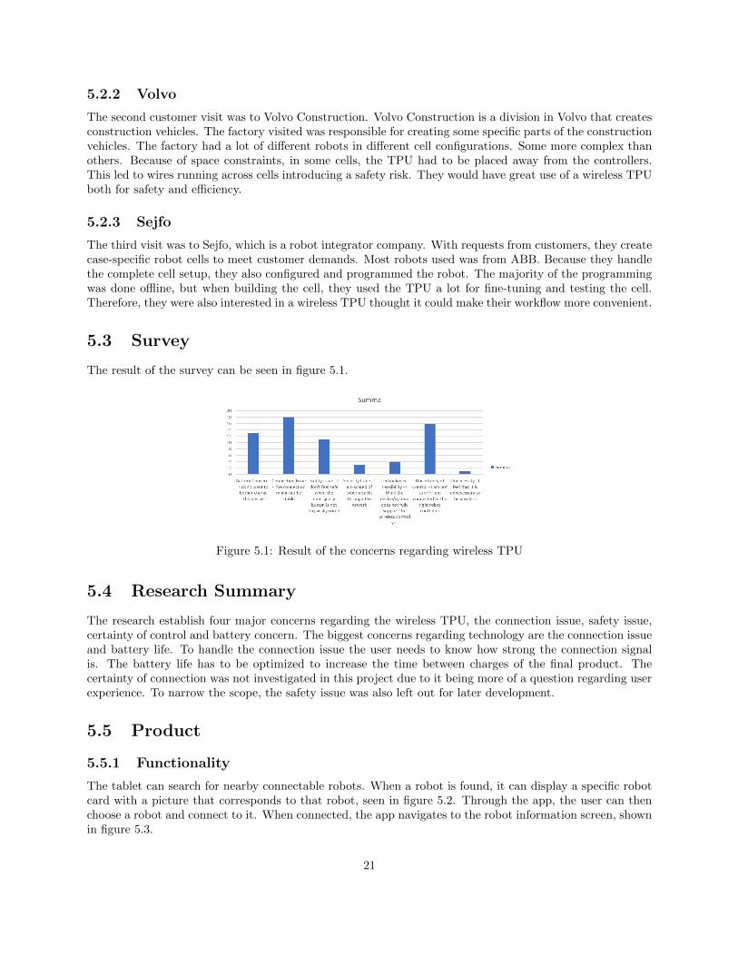
The result of the survey can be seen in figure 5.1.
Figure 5.1: Result of the concerns regarding wireless TPU
5.4 Research Summary
The research establish four major concerns regarding the wireless TPU, the connection issue, safety issue,certainty of control and battery concern. The biggest concerns regarding technology are the connection issueand battery life. To handle the connection issue the user needs to know how strong the connection signalis. The battery life has to be optimized to increase the time between charges of the final product. Thecertainty of connection was not investigated in this project due to it being more of a question regarding userexperience. To narrow the scope, the safety issue was also left out for later development.
5.5 Product
5.5.1 Functionality
The tablet can search for nearby connectable robots. When a robot is found, it can display a specific robotcard with a picture that corresponds to that robot, seen in figure 5.2. Through the app, the user can thenchoose a robot and connect to it. When connected, the app navigates to the robot information screen, shownin figure 5.3.
21

Figure 5.2: Overview of the App when displaying robots. Here one is named Orange and on named Red
Figure 5.3: Overview of the App when connected to a robot. Connected to a robot named Orange
22

When connected to a robot the user can send a start or a stop command to the robot. This starts andstops the execution of the robot’s task. When the tablet chooses to connect to a different robot, the oldconnection is automatically disabled. The robot then progresses back into a connectable state.Furthermore, the signal strength indicator works as intended. The tablet can read the non-connectableadvertisements and extract the information regarding the signal strength. The value on the screen is thenupdated live in the application.
5.5.2 Interface
The design interface of the application was discussed with the collaborative of the project to fit the proposal.However, the framework was finally designed by the collaborative of the project. When the design wascomplete, programming of the application could be completed Front-end was programmed to fit the back-end and the suggested design. The results of the implemented design can be seen in figure 5.2 and 5.3
5.6 Test at ABB
Main test results were:
• All participants were able to complete the test without supervision. This included all steps of the testconfiguration.
• All participants were able to complete the test without supervision. This included all steps of the testconfiguration.
• The overall response on the test was positive. Most of the participants felt like the app was intuitive,quick and responsive
• When compared to the regular wired TPU, most of the participants thought the wireless one was betterfor controlling multiple robots.
• When compared to the regular wired TPU, most of the participants thought the wireless one was betterfor controlling multiple robots.
The test resulted in all participants being able to complete the test without supervision. This included allsteps of the test configuration. The time was varying but the maximum time it took was about 3 minutes.
The overall response to the test was positive. Most of the participants felt like the app was intuitive, quickand responsive. When compared to the regular wired TPU, most of the participants thought the wirelessone was better for controlling multiple robots. The only complaint was the lack of features. The featuresmissed were the ones included in the regular TPU.
23

6. Discussion
6.1 Overall Product Performance
Comparing the wired TPU to the device developed in this thesis is complicated, due to the difference incomplexity and the greater usage range of the wired TPU. Nevertheless, it is possible to make a validcomparison of the specific task the developed product can handle.
Considering the results of the specific task of the developed product, it performs well. It handles thedisplay and connection of the robots in a user-friendly way. The time it takes to establish a connection to arobot was fast and responsive. When connected, the implemented commands were also fast with lowlatency.
The test that some of the employers at ABB did also show the easy usage of the wireless TPU. The complaintsabout the features were expected and are because of the simplicity of the final product as it is right now.
6.2 Hardware
The hardware in this project was kept to a minimum. According to the research, this was one of the criteria.The uncomplicated hardware allowed for a more straightforward software solution. The software uses thebuilt-in Bluetooth modems on both devices. This resulted in lower dependence on third-party supplements.Furthermore, it helped to reduce the size of the end product. Because of its size, there is no problem toattach it to the robot controller without causing a disturbance to the overall setup. Finally, the minimumhardware helped to keep the overall price of the product at a minimum.
6.3 Software
6.3.1 Challenges
Considering that this project was so different from any available solution, a lot of time was invested infinding out how a technical solution could look like and if it was at all possible. The author’s limitedprevious experience of Bluetooth programming resulted in a longer off distance. To note is also that therewas no local Bluetooth experience within the software group at ABB, so learning had to be done throughoutside sources.
For the Bluetooth functionality of the Windows part of the setup, it was concluded quickly that it wouldfunction and could be adapted to this project. This was due to the well documented API’s provided byMicrosoft. The documentation had short examples of each part of the API showcasing how it should beoperated.
24

Bluetooth development in Linux was on the other hand not well documented. This is because there is notone single company responsible for Bluetooth maintenance. Specific examples could be found, but nonethat would fit this project. The problem with the given specific examples was that they could not alter theadvertisement to meet the requirement for this project. Therefore, the advertising part of the server had tobe done separately from the regular python script. Even when using Linux terminal commands, thedocumentation was minimal. The hardest part was to navigate and find the correct information in theBluetooth Core specification and transform the information into valid commands to use in the terminal.However, when all UNIX commands and all Bluetooth ids were understood, the capability of altering theadvertisement was excellent.
Bluetooth events on the Linux operating system occur on a low level. As a result, low-level communicationof the operating system needed to be studied and understood. The documentation specific for Bluetoothevents was modest, but the global communication system was described in detail.
The communication between the server and the robot controller also had to be investigated. This wassomewhat well documented, but software engineers at ABB could guide me through the development. Someproblems occurred when transferring the communication from a testing computer to the Raspberry Pi. Thiswas due to the Raspbian operating system’s automatic IP address configuration failed toward the robot.Therefore, the IP address on the Raspberry Pi had to be manually modified.
6.3.2 Final result
In general, the product performed well. The application runs smoothly and has quick responses to userinput. Furthermore, the test participants thought the app had a modern and intuitive look. The back-endof the application functioned as intended without failures. Since the back-end also was built to be easy todevelop further and was not just built for this specific task, this was a good result.
The software was built in a way that performed well, but also with adaptability in mind. In a furtherdevelopment, it is easy to read and add new features. It was built upon well-supported APIs withguaranteed future support and no small custom third-party applications. This ensures that developmentcan continue without any major changes to the software.
The choice of Bluetooth was proven successful for the given project. It could handle the needed datatransfer quickly and accurately. The conductibility of the protocol was also shown to not only be useful inthe project now but also for further development. The protocol did not show any signs of limitations onwhich it failed to meet the requirement of the project.
The problems which were focus on, the battery and connection issue was handle by the prototype. Bydeveloping and using Bluetooth low energy, the final product energy efficacy was optimized to increasebattery life. Furthermore, the connection issue was handled by developing a signal strength indicator.Because of this, the end-user can make sure to get an understanding in real-time if of the current wirelessconnection state.
25

7. Conclusions
When the project started four goals were set. Although, together with the supervisor at ABB, these goalswere determined to be more of a guideline. This was due to the broad subject and that the main goal wasto be established after the research. After having the result, it is clear that the initial goals were met. Thegoals were:
• Investigate if it is possible to control a industrial robot without the use of wires.
• Present what challenges might occur when removing a wired connection
• Develop a product which can prove the functionality of the wireless connection
The first two goals were satisfied through interviews, survey and customer visits. By obtaining informationand discussing with different people with various views of the TPU, it was established that it is possible tocreate a wireless TPU and would be of high interest. Further, the research presented part of what challengesmight occur in the future. After the background research, enough knowledge was attained to able thevisualized the end product. Therefore, the technical implementation could take place. The final technicalsolution fulfilled goal three of the thesis.
7.1 Further developments
Since this would only be a start platform for further development, there is a lot of things that must beadded and fixed before it could be used as a finished product.
The connection between the robot and the Teach Pendant should be encrypted to increase security. TheBluetooth protocol has built-in encryption available, which was not implemented in this project due totime restraints.
More features must be added to the application and the server. The product showcases the concept of onefeature which could be further extended to include more. Furthermore, the advertisements should includemore data about the robot. As of now, the advertisement has unused ”empty” data in the advertisementpackage. The advertisements could contain different statuses of the robot, such as what mode it is in, whatprogram it runs or who it is connected to. However, one can argue that this should be kept as it is andinstead be adapted to any requirements specified by an end customer.
The emergency stop button was not implemented in this project. To replace a Teach Pendant, this must beimplemented. The emergency stop button cannot be handled over Bluetooth because it always has to beconnected. This could be solved by an add-on to the tablet, which is connected to the factory Wi-Finetwork or 5G. Because of the need for low latency and the fact that it always has to be connected, 5Gcould be suitable to handle this.
26

Further testing of user experience must be done. Since some people who tested this product thought the ideaof a map overview to choose robot would help, this might be a way forward. If this would seem necessary inthe future, one should add the technology of UWB to the tablet and the robots.
27
Bibliography
[1] (2012). Robots and robotic devices - iso 8373:2012, [Online]. Available: https://www.iso.org/obp/ui/%5C#iso:std:iso:8373:ed-2:v1:en (visited on 04/13/2020).
[2] ABB. (2020). Abb robotics, [Online]. Available: https://new.abb.com/products/robotics/ (visitedon 04/23/2020).
[3] RobotWorx, “What are the main types of robots?”, [Online]. Available: https://www.robots.com/faq/what-are-the-main-types-of-robots (visited on 05/28/2020).
[4] ABB. (2020). Abb robotics, robot irb-4400, [Online]. Available: https://new.abb.com/products/robotics/industrial-robots/irb-4400 (visited on 04/22/2020).
[5] ——, (2020). Abb robotics, controllers, [Online]. Available:https://new.abb.com/products/robotics/controllers (visited on 04/22/2020).
[6] ——, “Abb mutltimove”, 2004. [Online]. Available: https : / / library . e . abb . com / public /
734fb908d1c8ee50c12576dd005b69d0/ABB%5C%20MultiMove%5C%20functionality.pdf (visited on05/28/2020).
[7] ——, (2020). Abb robotics, controller: Omnicore, [Online]. Available:https://new.abb.com/products/robotics/controllers/omnicore (visited on 04/22/2020).
[8] NotebookCheck, “Article about lenovo thinkpad”, [Online]. Available: https://www.notebookcheck.net/Lenovo-ThinkPad-10-Multimode-Tablet-Review.121349.0.html (visited on 06/18/2020).
[9] Raspberry.org, “Raspbery pi 4 model b”, [Online]. Available: https://www.raspberrypi.org/
products/raspberry-pi-4-model-b/ (visited on 06/18/2020).
[10] S. Emami, UWB Communication Systems: Conventional and 60 GHz. Springer, 2013.
[11] J. T. J. Penttinen, “5g explained”, in. Wiley, 2019, ch. 1.2.
[12] B. Sig, “Bluetooth core specification”, in. 2019, vol. 1, ch. 1.1, p. 189.
[13] ——, “Bluetooth core specification”, in. 2019, vol. 4, ch. 7.8.5, p. 2482.
[14] ——, “Bluetooth core specification”, in. 2019, vol. 4, ch. 7.8.6, p. 2486.
[15] ——, “Bluetooth core specification”, in. 2019, vol. 3, ch. 11, p. 1392.
[16] Microsoft, “Bluetooth gatt client”, [Online]. Available: https://docs.microsoft.com/en- us/
windows/uwp/devices-sensors/gatt-client (visited on 03/12/2020).
[17] B. Sig, “Bluetooth manufacturer id list”, in. 2020. [Online]. Available: https://www.bluetooth.com/specifications/assigned-numbers/company-identifiers/ (visited on 05/15/2020).
28