Embed Size (px)
Citation preview

388 IEEE TRANSACTIONS ON BIOMEDICAL CIRCUITS AND SYSTEMS, VOL. 3, NO. 6, DECEMBER 2009
Wireless Micropower Instrumentation forMultimodal Acquisition of Electrical and
Chemical Neural ActivityMohsen Mollazadeh, Student Member, IEEE, Kartikeya Murari, Student Member, IEEE,
Gert Cauwenberghs, Senior Member, IEEE, and Nitish V. Thakor, Fellow, IEEE
Abstract—The intricate coupling between electrical and chem-ical activity in neural pathways of the central nervous system,and the implication of this coupling in neuropathologies, suchas Parkinson’s disease, motivates simultaneous monitoring ofneurochemical and neuropotential signals. However, to date,neurochemical sensing has been lacking in integrated clinicalinstrumentation as well as in brain-computer interfaces (BCI).Here, we present an integrated system capable of continuousacquisition of data modalities in awake, behaving subjects. Itfeatures one channel each of a configurable neuropotential anda neurochemical acquisition system. The electrophysiologicalchannel is comprised of a 40-dB gain, fully differential amplifierwith tunable bandwidth from 140 Hz to 8.2 kHz. The amplifieroffers input-referred noise below 2 ��� for all bandwidthsettings. The neurochemical module features a picoampere sensi-tivity potentiostat with a dynamic range spanning six decades frompicoamperes to microamperes. Both systems have independenton-chip, configurable �� analog-to-digital converters (ADCs)with programmable digital gain and resolution. The system wasalso interfaced to a wireless power harvesting and telemetrymodule capable of powering up the circuits, providing clocks forADC operation, and telemetering out the data at up to 32 kb/sover 3.5 cm with a bit-error rate of less than �� �. Characteri-zation and experimental results from the electrophysiological andneurochemical modules as well as the full system are presented.
Index Terms—Brain–computer interface (BCI), biopotentialamplifier, chemical sensing, digital telemetry, electrocorticogram(ECOG), electroencephalogram (EEG), inductive coupling, mi-cropower instrumentation, neural interface, neurotransmitters,potentiostat.
I. INTRODUCTION
B RAIN-COMPUTER interfaces (BCI) for neurologicmonitoring and neural prostheses rely on sensitive
recording of neural activity in the brain which manifests in sev-eral signal modalities, including electrical signals such as action
Manuscript received April 14, 2009; revised July 07, 2009. First publishedNovember 03, 2009; current version published November 25, 2009. This workwas supported in part by NIH/NIA, in part by R01AG029681, in part by NIHMH062444-065296, and in part by the Whitaker Foundation. This paper wasrecommended by Associate Editor S.-C. Liu.
M. Mollazadeh, K. Murari, and N. Thakor are with the Biomedical Engi-neering Department, Johns Hopkins University, Baltimore, MD 21205 USA(e-mail: [email protected]).
G. Cauwenberghs is with the Department of Bioengineering, Jacobs Schoolof Engineering, University of California San Diego, La Jolla, CA 92093 USA(e-mail: [email protected]).
Color versions of one or more of the figures in this paper are available onlineat http://ieeexplore.ieee.org.
Digital Object Identifier 10.1109/TBCAS.2009.2031877
potentials (spikes) and local field potentials (LFP) in the brain,and electrocorticogram (ECoG) and electroencephalogram(EEG) signals on the brain surface and scalp [1]. Completelylacking from BCI systems to date is the recording of chem-ical neural activity, which offers an important neural signalmodality for decoding the brain state. These signals are furtherimplicated in several diseases of the central nervous system. Ifthe only purpose of a BCI system is to control a cursor or tomove a robotic arm [2]–[4], electrical recordings would suffice.However, a neurochemical monitoring module may advance thefuture applications of clinical BCI systems, such as closed-loopdeep brain stimulation (DBS) for Parkinson’s treatment [5].
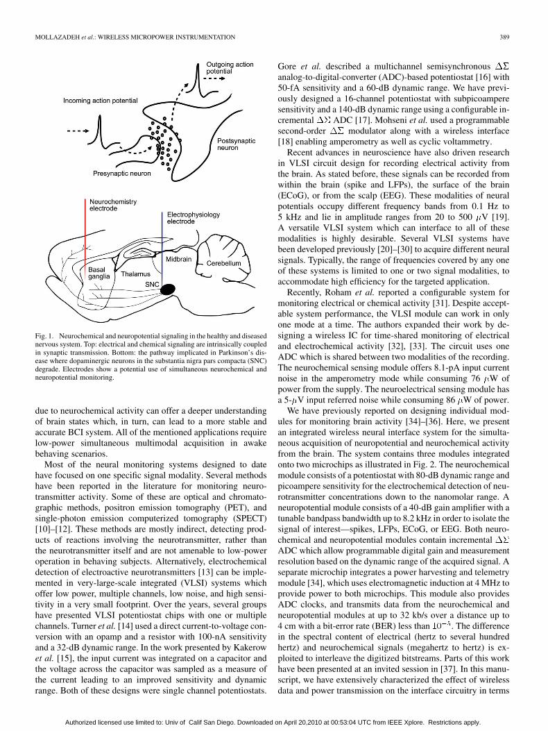
Electrical and chemical neural activity are tightly coupled inthe central nervous system. The presynaptic cells release excita-tory or inhibitory neurotransmitters into the synapse upon the ar-rival of a nerve impulse [6] as illustrated in Fig. 1. These chem-ical messenger molecules, such as dopamine and glutamate,bind to receptors on the postsynaptic cell and cause excitatoryor inhibitory postsynaptic potentials (EPSPs and IPSPs). Theneuron integrates all of the postsynaptic potentials and decideswhether to fire an action potential or not. The abnormal func-tioning of this signaling cascade causes severe damage to theunderlying cellular substrates. In aging-related neurodegenera-tive disorders, such as Parkinson’s disease, motor functions aredisrupted due to the death of dopaminergic neurons in substantianigra which project to the striatum. This pathway is shown inFig. 1. In case of cardiac arrest (CA), uncontrolled neurotrans-mitter release due to the absence of modulatory electrical ac-tivity in the brain is the basis of glutamate excitotoxicity whichleads to excessive neuronal cell death [7]. Chronic observationof both signals in awake behaving subjects after CA is neededto evaluate the effect of treatments, such as hypothermia [8] onrecovery after the brain injury. Other neurotransmitters, such asnitric oxide (NO), are mediators in neurovascular coupling andmonitoring their activity can enhance the understanding of cere-brovascular pathology during aging [9].
The interplay between electrical and neurochemical activityis also implicated in several basic neural pathways, such asrewards and learning, and has been neglected in BCI systems.This neurochemical activity contains information about the re-lationship between presynaptic and postsynaptic activity which,in turn, can modulate LFP activity. The neurochemical activitymay also result in the neuronal modulations or rhythms whichcan be observed in ECoG or EEG recordings. These signalmodalities offer a different perspective on neural informationfor BCI systems. The generation or modulation of these signals
1932-4545/$26.00 © 2009 IEEE
Authorized licensed use limited to: Univ of Calif San Diego. Downloaded on April 20,2010 at 00:53:04 UTC from IEEE Xplore. Restrictions apply.
MOLLAZADEH et al.: WIRELESS MICROPOWER INSTRUMENTATION 389
Fig. 1. Neurochemical and neuropotential signaling in the healthy and diseasednervous system. Top: electrical and chemical signaling are intrinsically coupledin synaptic transmission. Bottom: the pathway implicated in Parkinson’s dis-ease where dopaminergic neurons in the substantia nigra pars compacta (SNC)degrade. Electrodes show a potential use of simultaneous neurochemical andneuropotential monitoring.
due to neurochemical activity can offer a deeper understandingof brain states which, in turn, can lead to a more stable andaccurate BCI system. All of the mentioned applications requirelow-power simultaneous multimodal acquisition in awakebehaving scenarios.
Most of the neural monitoring systems designed to datehave focused on one specific signal modality. Several methodshave been reported in the literature for monitoring neuro-transmitter activity. Some of these are optical and chromato-graphic methods, positron emission tomography (PET), andsingle-photon emission computerized tomography (SPECT)[10]–[12]. These methods are mostly indirect, detecting prod-ucts of reactions involving the neurotransmitter, rather thanthe neurotransmitter itself and are not amenable to low-poweroperation in behaving subjects. Alternatively, electrochemicaldetection of electroactive neurotransmitters [13] can be imple-mented in very-large-scale integrated (VLSI) systems whichoffer low power, multiple channels, low noise, and high sensi-tivity in a very small footprint. Over the years, several groupshave presented VLSI potentiostat chips with one or multiplechannels. Turner et al. [14] used a direct current-to-voltage con-version with an opamp and a resistor with 100-nA sensitivityand a 32-dB dynamic range. In the work presented by Kakerowet al. [15], the input current was integrated on a capacitor andthe voltage across the capacitor was sampled as a measure ofthe current leading to an improved sensitivity and dynamicrange. Both of these designs were single channel potentiostats.
Gore et al. described a multichannel semisynchronousanalog-to-digital-converter (ADC)-based potentiostat [16] with50-fA sensitivity and a 60-dB dynamic range. We have previ-ously designed a 16-channel potentiostat with subpicoamperesensitivity and a 140-dB dynamic range using a configurable in-cremental ADC [17]. Mohseni et al. used a programmablesecond-order modulator along with a wireless interface[18] enabling amperometry as well as cyclic voltammetry.
Recent advances in neuroscience have also driven researchin VLSI circuit design for recording electrical activity fromthe brain. As stated before, these signals can be recorded fromwithin the brain (spike and LFPs), the surface of the brain(ECoG), or from the scalp (EEG). These modalities of neuralpotentials occupy different frequency bands from 0.1 Hz to5 kHz and lie in amplitude ranges from 20 to 500 V [19].A versatile VLSI system which can interface to all of thesemodalities is highly desirable. Several VLSI systems havebeen developed previously [20]–[30] to acquire different neuralsignals. Typically, the range of frequencies covered by any oneof these systems is limited to one or two signal modalities, toaccommodate high efficiency for the targeted application.
Recently, Roham et al. reported a configurable system formonitoring electrical or chemical activity [31]. Despite accept-able system performance, the VLSI module can work in onlyone mode at a time. The authors expanded their work by de-signing a wireless IC for time-shared monitoring of electricaland electrochemical activity [32], [33]. The circuit uses oneADC which is shared between two modalities of the recording.The neurochemical sensing module offers 8.1-pA input currentnoise in the amperometry mode while consuming 76 W ofpower from the supply. The neuroelectrical sensing module hasa 5- V input referred noise while consuming 86 W of power.
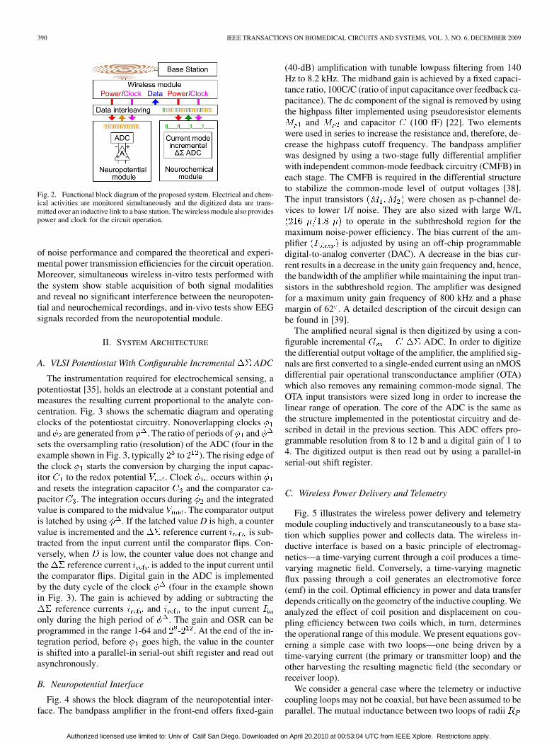
We have previously reported on designing individual mod-ules for monitoring brain activity [34]–[36]. Here, we presentan integrated wireless neural interface system for the simulta-neous acquisition of neuropotential and neurochemical activityfrom the brain. The system contains three modules integratedonto two microchips as illustrated in Fig. 2. The neurochemicalmodule consists of a potentiostat with 80-dB dynamic range andpicoampere sensitivity for the electrochemical detection of neu-rotransmitter concentrations down to the nanomolar range. Aneuropotential module consists of a 40-dB gain amplifier with atunable bandpass bandwidth up to 8.2 kHz in order to isolate thesignal of interest—spikes, LFPs, ECoG, or EEG. Both neuro-chemical and neuropotential modules contain incrementalADC which allow programmable digital gain and measurementresolution based on the dynamic range of the acquired signal. Aseparate microchip integrates a power harvesting and telemetrymodule [34], which uses electromagnetic induction at 4 MHz toprovide power to both microchips. This module also providesADC clocks, and transmits data from the neurochemical andneuropotential modules at up to 32 kb/s over a distance up to4 cm with a bit-error rate (BER) less than . The differencein the spectral content of electrical (hertz to several hundredhertz) and neurochemical signals (megahertz to hertz) is ex-ploited to interleave the digitized bitstreams. Parts of this workhave been presented at an invited session in [37]. In this manu-script, we have extensively characterized the effect of wirelessdata and power transmission on the interface circuitry in terms
Authorized licensed use limited to: Univ of Calif San Diego. Downloaded on April 20,2010 at 00:53:04 UTC from IEEE Xplore. Restrictions apply.
390 IEEE TRANSACTIONS ON BIOMEDICAL CIRCUITS AND SYSTEMS, VOL. 3, NO. 6, DECEMBER 2009
Fig. 2. Functional block diagram of the proposed system. Electrical and chem-ical activities are monitored simultaneously and the digitized data are trans-mitted over an inductive link to a base station. The wireless module also providespower and clock for the circuit operation.
of noise performance and compared the theoretical and experi-mental power transmission efficiencies for the circuit operation.Moreover, simultaneous wireless in-vitro tests performed withthe system show stable acquisition of both signal modalitiesand reveal no significant interference between the neuropoten-tial and neurochemical recordings, and in-vivo tests show EEGsignals recorded from the neuropotential module.
II. SYSTEM ARCHITECTURE
A. VLSI Potentiostat With Configurable Incremental ADC
The instrumentation required for electrochemical sensing, apotentiostat [35], holds an electrode at a constant potential andmeasures the resulting current proportional to the analyte con-centration. Fig. 3 shows the schematic diagram and operatingclocks of the potentiostat circuitry. Nonoverlapping clocksand are generated from . The ratio of periods of andsets the oversampling ratio (resolution) of the ADC (four in theexample shown in Fig. 3, typically to ). The rising edge ofthe clock starts the conversion by charging the input capac-itor to the redox potential . Clock occurs withinand resets the integration capacitor and the comparator ca-pacitor . The integration occurs during and the integratedvalue is compared to the midvalue . The comparator outputis latched by using . If the latched value D is high, a countervalue is incremented and the reference current is sub-tracted from the input current until the comparator flips. Con-versely, when is low, the counter value does not change andthe reference current is added to the input current untilthe comparator flips. Digital gain in the ADC is implementedby the duty cycle of the clock (four in the example shownin Fig. 3). The gain is achieved by adding or subtracting the
reference currents and to the input currentonly during the high period of . The gain and OSR can beprogrammed in the range 1-64 and - . At the end of the in-tegration period, before goes high, the value in the counteris shifted into a parallel-in serial-out shift register and read outasynchronously.
B. Neuropotential Interface
Fig. 4 shows the block diagram of the neuropotential inter-face. The bandpass amplifier in the front-end offers fixed-gain
(40-dB) amplification with tunable lowpass filtering from 140Hz to 8.2 kHz. The midband gain is achieved by a fixed capaci-tance ratio, 100C/C (ratio of input capacitance over feedback ca-pacitance). The dc component of the signal is removed by usingthe highpass filter implemented using pseudoresistor elements
and and capacitor (100 fF) [22]. Two elementswere used in series to increase the resistance and, therefore, de-crease the highpass cutoff frequency. The bandpass amplifierwas designed by using a two-stage fully differential amplifierwith independent common-mode feedback circuitry (CMFB) ineach stage. The CMFB is required in the differential structureto stabilize the common-mode level of output voltages [38].The input transistors were chosen as p-channel de-vices to lower 1/f noise. They are also sized with large W/L
to operate in the subthreshold region for themaximum noise-power efficiency. The bias current of the am-plifier is adjusted by using an off-chip programmabledigital-to-analog converter (DAC). A decrease in the bias cur-rent results in a decrease in the unity gain frequency and, hence,the bandwidth of the amplifier while maintaining the input tran-sistors in the subthreshold region. The amplifier was designedfor a maximum unity gain frequency of 800 kHz and a phasemargin of 62 . A detailed description of the circuit design canbe found in [39].
The amplified neural signal is then digitized by using a con-figurable incremental ADC. In order to digitizethe differential output voltage of the amplifier, the amplified sig-nals are first converted to a single-ended current using an nMOSdifferential pair operational transconductance amplifier (OTA)which also removes any remaining common-mode signal. TheOTA input transistors were sized long in order to increase thelinear range of operation. The core of the ADC is the same asthe structure implemented in the potentiostat circuitry and de-scribed in detail in the previous section. This ADC offers pro-grammable resolution from 8 to 12 b and a digital gain of 1 to4. The digitized output is then read out by using a parallel-inserial-out shift register.
C. Wireless Power Delivery and Telemetry
Fig. 5 illustrates the wireless power delivery and telemetrymodule coupling inductively and transcutaneously to a base sta-tion which supplies power and collects data. The wireless in-ductive interface is based on a basic principle of electromag-netics—a time-varying current through a coil produces a time-varying magnetic field. Conversely, a time-varying magneticflux passing through a coil generates an electromotive force(emf) in the coil. Optimal efficiency in power and data transferdepends critically on the geometry of the inductive coupling. Weanalyzed the effect of coil position and displacement on cou-pling efficiency between two coils which, in turn, determinesthe operational range of this module. We present equations gov-erning a simple case with two loops—one being driven by atime-varying current (the primary or transmitter loop) and theother harvesting the resulting magnetic field (the secondary orreceiver loop).
We consider a general case where the telemetry or inductivecoupling loops may not be coaxial, but have been assumed to beparallel. The mutual inductance between two loops of radii
Authorized licensed use limited to: Univ of Calif San Diego. Downloaded on April 20,2010 at 00:53:04 UTC from IEEE Xplore. Restrictions apply.

MOLLAZADEH et al.: WIRELESS MICROPOWER INSTRUMENTATION 391
Fig. 3. Schematic block diagram of the VLSI potentiostat circuitry. Clocks on the lower right show an example of operation for gain 4 and oversampling ratio 4.
Fig. 4. Functional block diagram for the neuropotential interface channel. The channel consists of a bandpass amplifier and a programmable ADC. A circuitschematic of the fully differential amplifier is shown on the left.
Fig. 5. Functional block diagram for the power harvesting and telemetry block.
and with a planar separation of and an axial offset of isgiven by [40]
(1)
with
(2)
(3)
(4)
(5)
where and are complete elliptic integrals of the firstand second kind, respectively, and is the permittivity of themedium.
Once the mutual inductance between the two coils is deter-mined, the voltage induced in the receiving coil can bewritten as [34]
(6)
Authorized licensed use limited to: Univ of Calif San Diego. Downloaded on April 20,2010 at 00:53:04 UTC from IEEE Xplore. Restrictions apply.
392 IEEE TRANSACTIONS ON BIOMEDICAL CIRCUITS AND SYSTEMS, VOL. 3, NO. 6, DECEMBER 2009
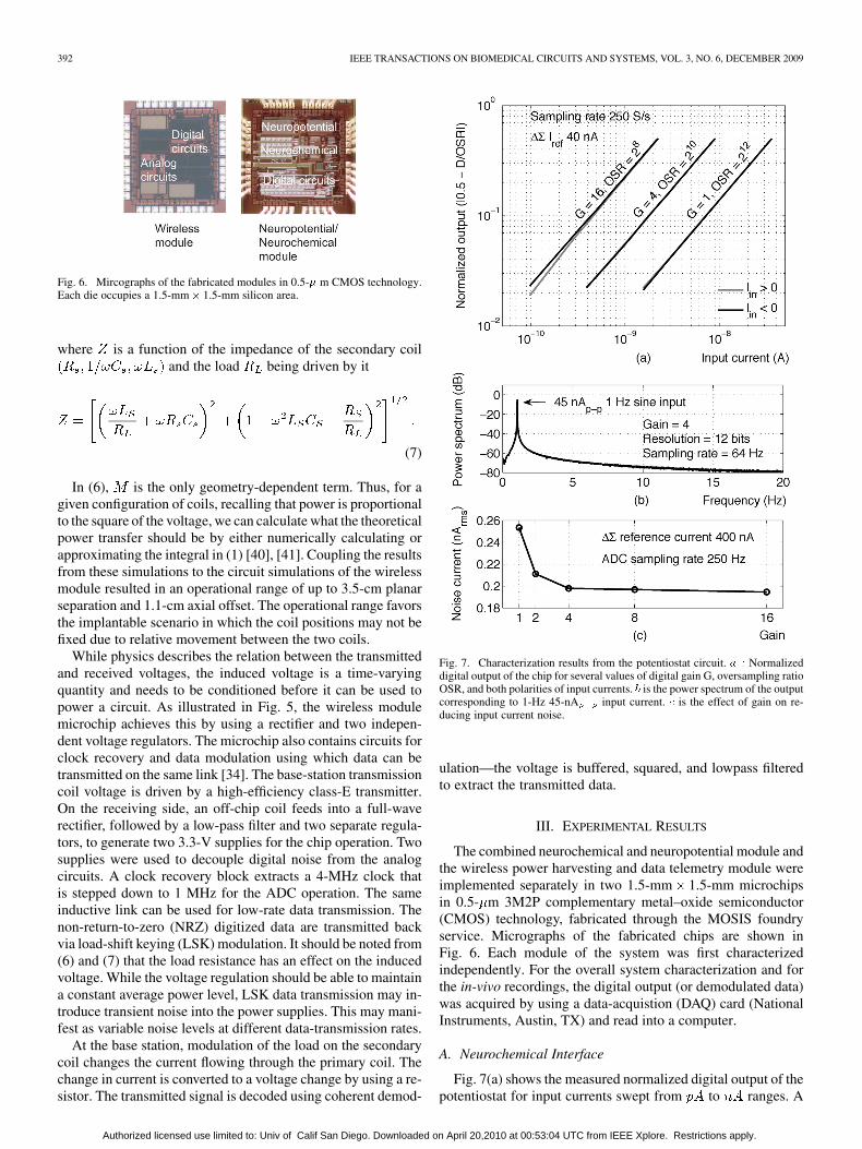
Fig. 6. Mircographs of the fabricated modules in 0.5-� m CMOS technology.Each die occupies a 1.5-mm� 1.5-mm silicon area.
where is a function of the impedance of the secondary coiland the load being driven by it
(7)
In (6), is the only geometry-dependent term. Thus, for agiven configuration of coils, recalling that power is proportionalto the square of the voltage, we can calculate what the theoreticalpower transfer should be by either numerically calculating orapproximating the integral in (1) [40], [41]. Coupling the resultsfrom these simulations to the circuit simulations of the wirelessmodule resulted in an operational range of up to 3.5-cm planarseparation and 1.1-cm axial offset. The operational range favorsthe implantable scenario in which the coil positions may not befixed due to relative movement between the two coils.
While physics describes the relation between the transmittedand received voltages, the induced voltage is a time-varyingquantity and needs to be conditioned before it can be used topower a circuit. As illustrated in Fig. 5, the wireless modulemicrochip achieves this by using a rectifier and two indepen-dent voltage regulators. The microchip also contains circuits forclock recovery and data modulation using which data can betransmitted on the same link [34]. The base-station transmissioncoil voltage is driven by a high-efficiency class-E transmitter.On the receiving side, an off-chip coil feeds into a full-waverectifier, followed by a low-pass filter and two separate regula-tors, to generate two 3.3-V supplies for the chip operation. Twosupplies were used to decouple digital noise from the analogcircuits. A clock recovery block extracts a 4-MHz clock thatis stepped down to 1 MHz for the ADC operation. The sameinductive link can be used for low-rate data transmission. Thenon-return-to-zero (NRZ) digitized data are transmitted backvia load-shift keying (LSK) modulation. It should be noted from(6) and (7) that the load resistance has an effect on the inducedvoltage. While the voltage regulation should be able to maintaina constant average power level, LSK data transmission may in-troduce transient noise into the power supplies. This may mani-fest as variable noise levels at different data-transmission rates.
At the base station, modulation of the load on the secondarycoil changes the current flowing through the primary coil. Thechange in current is converted to a voltage change by using a re-sistor. The transmitted signal is decoded using coherent demod-
Fig. 7. Characterization results from the potentiostat circuit. � � Normalizeddigital output of the chip for several values of digital gain G, oversampling ratioOSR, and both polarities of input currents. � is the power spectrum of the outputcorresponding to 1-Hz 45-nA input current. � is the effect of gain on re-ducing input current noise.
ulation—the voltage is buffered, squared, and lowpass filteredto extract the transmitted data.
III. EXPERIMENTAL RESULTS
The combined neurochemical and neuropotential module andthe wireless power harvesting and data telemetry module wereimplemented separately in two 1.5-mm 1.5-mm microchipsin 0.5- m 3M2P complementary metal–oxide semiconductor(CMOS) technology, fabricated through the MOSIS foundryservice. Micrographs of the fabricated chips are shown inFig. 6. Each module of the system was first characterizedindependently. For the overall system characterization and forthe in-vivo recordings, the digital output (or demodulated data)was acquired by using a data-acquistion (DAQ) card (NationalInstruments, Austin, TX) and read into a computer.
A. Neurochemical Interface
Fig. 7(a) shows the measured normalized digital output of thepotentiostat for input currents swept from to ranges. A
Authorized licensed use limited to: Univ of Calif San Diego. Downloaded on April 20,2010 at 00:53:04 UTC from IEEE Xplore. Restrictions apply.

MOLLAZADEH et al.: WIRELESS MICROPOWER INSTRUMENTATION 393
Fig. 8. Neuropotential interface characterization results. � is the amplifier’s frequency response for various bandwidths by changing � from 0.1 to 8 �A and� is the power spectrum of the recorded output when a 1-m� 50-Hz sine wave is presented to the input.
model 6430 sourcemeter (Keithley, Inc., Cleveland, OH) wasprogrammed to vary the input current. The was set to 40nA and the system clock was 1 MHz. The digital gain and OSRwere programmed individually for each setting for a samplingrate of 250 S/s. As can be seen in the figure, the circuit offers awide dynamic range for all gain and resolution settings.
Fig. 7(b) shows the power spectrum of the potentiostat outputwhen presented with a 45-nA sinusoidal current at 1 Hz. The
was set to 400 nA. The gain and OSR were set to 4 andrespectively, resulting in a sampling rate of 64 S/s. Fig. 7(c)
shows the effect of the programmed ADC gain on root meansquare (rms) current noise. The OSR was changed for each gainto set the sampling rate to 250 Samples/s. Fig. 7(c) shows thepotentiostat input-referred current noise versus the digital gain.The output noise decreases from 1.5 least-significant bit (LSB)for a gain of 1 to 1.1 LSB for a gain of 16 (full scale of 12 b to8 b, respectively).
B. Neuropotential Interface
The measured gain and bandwidth of the closed-loop band-pass amplifier are shown in Fig. 8(a). The midband gain was39.6 dB. The amplifier’s bandwidth was adjustable from 140Hz to 8.2 kHz by tuning from 0.1 to 8 A and thelow-frequency cutoff was measured to be 0.24 Hz. The ampli-fier’s common-mode rejection ratio (CMRR) and power-supplyrejection ratio (PSRR) were larger than 76 dB for inputs be-tween 1 Hz and 10 kHz at an electrode offset of 50 mV. Theamplifier total harmonic distortion (THD) was below 1% forinputs within 9.4 . For a 250-Hz bandwidth (suitablefor EEG recording), the thermal noise level was approximately100 nV/ Hz. Integration of the PSD from 0.1 Hz to 5 kHzyielded an input-referred noise of 1.65 and a noiseefficiency factor (NEF) [42] of 3.2.
The power spectrum of the digitized output, when a 50-Hz1-m sine wave was presented to the amplifier, is shown inFig. 8(b). The amplifier bandwidth was set to 150 Hz. The ADCwas set to 10-b resolution and a gain of 1 leading to a samplingrate of 1 kSamples/s. The THD of the channel was measured to
be less than 0.3%. The channel noise in terms of LSB was 1.2LSB (2.5 ), which is suitable for monitoring all modalitiesof neural potentials.
C. Wireless Power Harvesting and Telemetry
The wireless power harvesting and telemetry module wascharacterized in two steps. First, only the inductive link wastested by driving the primary coil with a class-E amplifier andmonitoring the power delivered to a passive resistive load on thereceiving side. Next, the voltage induced in the secondary coilwas conditioned by the wireless module circuitry to characterizethe voltage regulation and data telemetry and their effect on theinput-referred noise of the neural interface.
The primary coil had a diameter of 50 mm and had 10 turns.The secondary coil also had 10 turns, but with a diameter of20 mm. While a larger secondary coil would harvest powermore efficiently, the size is constrained as the coil is meantto be implanted subcutaneously. The frequency of operationwas chosen as 4 MHz which has been shown to be optimal forpower transfer across biological tissue [43]. Resistive loads of10 k and 100 k were connected across the secondary coil.The coils were aligned parallel and coaxial, and the distancebetween them was varied from 10 to 30 mm. Fig. 9(a) showsthe ratio of the power received at distance to the power re-ceived at 10 mm at both loads. The figure also shows thetheoretical profile calculated from (6). As can be seen, for bothloads, the ratio of the power received as a function of followsthe same trend as the theoretical prediction, although it is con-sistently lower. This is possibly due to environmental losses notconsidered in (6). Also, we have assumed that the magnetic fieldgenerated by a coil is directly proportional to that generated bya single current carrying loop, which is not the case, given the3-D geometry of the implemented coils.
Fig. 9(b) shows similar results but for various offset distancesbetween the axes of the coils. Again, the measured values followthe same trends as the predicted values. The reduction is that theinduced voltage is less because the magnetic field increases inintensity going from the center to the periphery of the coil. This
Authorized licensed use limited to: Univ of Calif San Diego. Downloaded on April 20,2010 at 00:53:04 UTC from IEEE Xplore. Restrictions apply.

394 IEEE TRANSACTIONS ON BIOMEDICAL CIRCUITS AND SYSTEMS, VOL. 3, NO. 6, DECEMBER 2009
Fig. 9. Fraction of retained power versus displacement (a) parallel and (b) per-pendicular to coil axis for two different load conditions as well as theoreticalvalues.
Fig. 10. RF operation: 3.3-V regulated supply, 32-kHz data clock (generatedfrom the 4-MHz recovered clock), transmitted data, and demodulated data at thebase station.
makes up for the increased distance between the coils due to thelateral misalignment.
Fig. 10 shows an oscilloscope trace of the regulated 3.3-Vsupply used to power the neural interface chip (top panel).During the wireless operation of the system, the readout clock(second panel) is generated from the 1-MHz system clockprovided by the telemetry module. This clock was used toshift out the digitized neural data (third panel) that modulateda load on the secondary coil. The bottom panel shows thedemodulated data at the base station. Stable operation of thecircuit was achieved with up to 3.5-cm separation between thecoils (less than a 1% change in the regulated voltage supply).Data transmission was also tested up to 32 kb/s, resulting in abit-error rate (BER) of less than .
We also characterized the effect of wireless power deliveryon noise performance of the neuropotential interface system.
Fig. 11. Measured channel noise versus (a) coil separation and (b) data trans-mission rate at 25-mm coil separation. Error bars show the standard deviationsacross five measurements.
Fig. 11(a) shows the measured channel noise for different dis-tances between the coils. As expected, there is more noise in theharvested power supply than the wired power supply leading toan increase in the channel noise from 2 to 2.3 b compared tothe maximum noise of 1.1 b in the wired case. The measuredchannel noise decreased with increasing distance between thetwo coils, possibly due to reduced electromagnetic interference(EMI) with circuit operation at larger distances and reducedripple in the regulated supply voltage.
As described before, we used an LSK modulation schemeto transmit the low-data-rate EEG data back to the base sta-tion via the same inductive link. This load modulation on thereceiver coil results in a modulation of the rectified voltage atthe same rate. These fluctuations on the rectified voltage willresult in a noise on the regulated supply voltage. The noise onthe power supply will, in turn, change the input-referred noiseof the system. The relationship between the modulation of re-ceived voltage and input-referred noise of the system is highlynonlinear and is not modeled here. Nevertheless, to gain an in-tuitive understanding of the relationship and to determine theoptimal telemetry data rate, we characterized the circuit noiseperformance for different data-transmission rates.
Fig. 11(b) shows the channel input-referred noise versus thedata-transmission rate when the two coils were separated by 25mm. The rms value of the regulated voltage was 3.27 V. Thenoise increased rapidly for data rates of less than 5 kb/s. This islikely due to the nature of our modulation scheme, LSK, whichoperates by changing the load resistance driven by a secondarycoil. Assuming a repeated “10” data stream (square wave), from(6) and (7), it can be seen that the input going to the voltage reg-ulator will switch between two levels at the frequency of the datastream. The voltage regulator can be thought of as a proportionalcontroller that keeps the regulated voltage equal to a reference.The controller has a time constant which defines how fast itcan respond to changes in the input. For changes slower than ,the controller will be able to respond and change the output inrelation to the input. This manifests as a change in the power
Authorized licensed use limited to: Univ of Calif San Diego. Downloaded on April 20,2010 at 00:53:04 UTC from IEEE Xplore. Restrictions apply.
MOLLAZADEH et al.: WIRELESS MICROPOWER INSTRUMENTATION 395
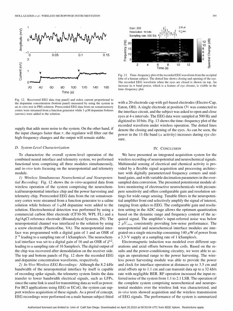
Fig. 12. Recovered EEG data (top panel) and redox current proportional tothe dopamine concentration (bottom panel) measured by using the system inan in-vitro test in PBS solution. Prerecorded EEG data from rat somatosensorycortex were streamed from a function generator while 1-�M dopamine boluses(arrows) were added to the solution.
supply that adds more noise to the system. On the other hand, ifthe input changes faster than , the regulator will filter out thehigh-frequency changes and the output will remain stable.
D. System-Level Characterization
To characterize the overall system-level operation of thecombined neural interface and telemetry system, we performedfunctional tests comprising all three modules simultaneously,and in-vivo tests focusing on the neuropotential and telemetrymodule.
1) Wireless Simultaneous Neurochemical and Neuropoten-tial Recording: Fig. 12 shows the in-vitro-acquired data fromwireless operation of the system comprising the neurochem-ical/neuropotential interface chip and the power harvesting andtelemetry chip. Prerecorded EEG data from the rat somatosen-sory cortex were streamed from a function generator to a salinesolution while boluses of 1- M dopamine were added to thesolution. Electrochemical detection was performed by using acommercial carbon fiber electrode (CF30-50, WPI, FL) and aAg/AgCl reference electrode (Bioanalytical Systems, IN). Theneuropotential channel was interfaced to the solution by usinga screw electrode (PlasticsOne, VA). The neuropotential inter-face was programmed with a digital gain of 1 and an OSR of
leading to a sampling rate of 1 kSamples/s. The neurochem-ical interface was set to a digital gain of 16 and an OSR of ,leading to a sampling rate of 16 Samples/s. The digital output ofthe chip was recovered after demodulation on the receiver side.The top and bottom panels of Fig. 12 show the recorded EEGand dopamine concentration waveforms, respectively.
2) In-Vivo Wireless EEG Recordings: Although the 8.2-kHzbandwidth of the neuropotential interface by itself is capableof recording spike signals, the telemetry system limits the datatransfer to lower bandwidth electrical signals, such as LFPs,since the same link is used for transmitting data as well as power.For BCI applications using EEG or ECoG, the system can sup-port wireless acquisition of these signals. As a proof of concept,EEG recordings were performed on a male human subject fitted
Fig. 13. Time–frequency plot of the recorded EEG waveform from the occipitallobe of a human subject. The dotted line shows closing and opening of the eye.The recorded EEG waveform when the eyes are closed is shown on top. Anincrease in � band power, which is a feature of eye closure, is visible in thetime–frequency plot.
with a 20-electrode cap with gel-based electrodes (Electro-Cap,Eaton, OH). A single electrode at position was connected tothe interface circuit, and the subject was asked to open and closeeyes at 4-s intervals. The EEG data were sampled at 500 Hz anddigitized to 10 bits. Fig. 13 shows the time–frequency plot of therecorded waveform under wireless operation. The dotted linesdenote the closing and opening of the eyes. As can be seen, thepower in the 11-Hz band ( activity) increases during eye clo-sure.
IV. CONCLUSION
We have presented an integrated acquisition system for thewireless recording of neuropotential and neurochemical signals.Multimodal sensing of electrical and chemical activity is pro-vided by a flexible signal acquisition and processing architec-ture with digitally parameterized frequency corners and mid-band gains, and with variable decimation parameters in the over-sampled data conversion. The presented potentiostat module al-lows monitoring of electroactive neurochemicals with picoam-pere sensitivity and offers configurable gain and resolution set-tings for wide-range sensing. Tunable filters in the neuropoten-tial amplifier front end selectively amplify the signal of interest,ranging from spikes to EEG. The configurable gain and resolu-tion setting in the ADC stage allows the optimum quantizationbased on the dynamic range and frequency content of the ac-quired signal. The amplifier’s input-referred noise was below2 , consistently providing low-noise performance. Theneuropotential and neurochemical interface modules are inte-grated on a single microchip consuming 140 W of power froma 3.3-V supply at a sampling rate of 1 kSamples/s.
Electromagnetic induction was modeled over different sep-arations and axial offsets between the coils. Based on the re-sults and the power-conditioning circuitry, we were able to as-sign an operational range to the power harvesting. The wire-less power harvesting module was able to provide the powerand clock for interface operation at distances up to 3.5 cm andaxial offsets up to 1.1 cm and can transmit data up to a 32-kb/srate with negligible BER. RF operation increased the input-re-ferred noise of the system from 1.1 to 2.1 LSB. The operation ofthe complete system comprising neurochemical and neuropo-tential modules over the wireless link was characterized, andin-vivo tests showed acquisition and the wireless transmissionof EEG signals. The performance of the system is summarized
Authorized licensed use limited to: Univ of Calif San Diego. Downloaded on April 20,2010 at 00:53:04 UTC from IEEE Xplore. Restrictions apply.

396 IEEE TRANSACTIONS ON BIOMEDICAL CIRCUITS AND SYSTEMS, VOL. 3, NO. 6, DECEMBER 2009
TABLE IPERFORMANCE SUMMARY OF THE SYSTEM
in Table I. To our knowledge, this is the only system which of-fers true synchronous monitoring of the neuropotential and neu-rochemical activity. Moreover, the wireless power transmissionmakes the system amenable for ambulatory monitoring. How-ever, the low-data-rate telemetry module restrains us from ac-quiring fast neural signals. Our future work includes designinghigh-data-rate RF links and simultaneous in-vivo monitoringof glutamate concentration and EEG from rat somatosensorycortex following cardiac arrest.
The presented system sets a framework for advancing bothclinical aspects of neuroengineering, and research aspects ofneuroscience. While typically used neural instrumentationsystems are purely electrical or use large and expensive in-strumentation for combined neurochemical and neuropotentialsensing, the presented integrated system opens a new avenuefor the real-time study of the interplay between neurochemicaland electrical activity in awake behaving animals. Applicationsof the system to neuroscience research include studying thecerebrovascular pathology of aging and monitoring of chemicaland electrical neural activity in normal and diseased brains.Applications to clinical neuroengineering include future gen-erations of the BCI system, detection of epileptic seizures,and monitoring EEG signals and excitotoxic neurotransmitteractivity following global ischemia.
ACKNOWLEDGMENT
The authors would like to thank C. Sauer and M. Stanacevicfor the previous design of power harvesting and the telemetrychip and H. Schwerdt and X. Wang for the experiment setup.Chips were fabricated through the MOSIS foundry service.
REFERENCES
[1] G. Dornhege, J. del R. Millan, T. Hinterberger, D. J. McFarland, andK.-R. Muller, Towards Brain-Computer Interfacing. Cambridge,MA: MIT Press, 2007.
[2] R. A. Andersen, S. Musallam, and B. Pesaran, “Selecting the signalsfor a brain machine interface,” Curr. Opn. Neurobiol., vol. 14, no. 6,pp. 720–726, 2004.
[3] J. R. Wolpaw, N. Birbaumer, D. J. McFarland, G. Pfurtscheller, and T.M. Vaughan, “Brain-computer interfaces for communication and con-trol,” Clin. Neurophysiol., vol. 113, no. 6, pp. 767–791, 2002.
[4] L. R. Hochberg, M. D. Serruya, G. M. Friehs, J. A. Mukand, M. Saleh,A. H. Caplan, A. Branner, D. Chen, R. D. Penn, and J. P. Donoghue,“Neuronal ensemble control of prosthetic devices by a human withtetraplegia,” Nature, vol. 442, no. 13, pp. 164–171, 2006.
[5] A. Murro, Y. D. Park, G. K. Bergey, E. H. Kossof, E. K. Ritzl, S. C.Karceski, K. Flynn, H. Choi, D. D. Spencer, B. B. Duckrow, and C.Seale, “Multicenter study of acute responsive stimulation in patientswith intractable epilepsy,” Epilepsia, vol. 44, no. S9, pp. 326–, 2003.
[6] M. Bear, B. Connors, and M. Paradiso, Neuroscience: Exploring theBrain. Baltimore, MD: Lippincott Williams Wilkins, 2006.
[7] M. Y. Globus, M. D. Ginsberg, and R. Busto, “Excitotoxic index—Abiochemical marker of selective vulnerability,” Neurosci. Lett., vol.127, pp. 39–42, Jun. 1991.
[8] R. G. Geocadin, M. A. Koenig, X. Jia, R. D. Stevens, and M. A. Pe-berdy, “Management of brain injury after resuscitation from cardiacarrest,” Neurologic Clinics, vol. 26, no. 2, pp. 487–506, 2008.
[9] E. Farkas and P. G. M. Luiten, “Cerebral microvascular pathology inaging and alzheimer’s disease,” Prog. Neurobiol., vol. 64, no. 6, pp.575–611, 2001.
[10] R. Braman and S. Hendrix, “Nanogram nitrite and nitrate determina-tion in environmental and biological materials by vanadium (III) re-duction with chemiluminescence detection,” Anal. Chem., vol. 61, pp.2715–2718, Dec. 1989.
[11] I. Baranowska and M. Zydron, “Liquid chromatography in the analysisof neurotransmitters and alkaloids,” J. Chromatogr. Sci., vol. 40, pp.224–228, Apr. 2002.
[12] R. Schlosser, “Detection of neurotransmitter interactions with PET andSPECT by pharmacological challenge paradigms,” Nervenarzt, vol. 71,pp. 9–18, Jan. 2000.
[13] T. Malinski and Z. Taha, “Nitric oxide release from a single cell mea-sured in situ by a porphyrinic-based microsensor,” Nature, vol. 358, pp.676–678, Aug. 1992.
[14] R. Turner, D. Harrison, and H. Baltes, “A CMOS potentiostat foramperometric chemical sensors,” IEEE J. Solid-State Circuits, vol.SSC-22, no. 3, pp. 473–478, Jun. 1987.
[15] R. Kakerow, H. Kappert, E. Spiegel, and Y. Manoli, “Low-powersingle-chip CMOS potentiostat,” in Proc. 8th Int. Conf. Solid-StateSensors and Actuators and Eurosensors IX. Transducers, Jun. 1995,vol. 1, pp. 142–145.
[16] A. Gore, S. Chakrabartty, S. Pal, and E. C. Alocilja, “A multichannelfemtoampere-sensitivity potentiostat array for biosensing applica-tions,” IEEE Trans. Circuits Syst. I, vol. 53, no. 11, pp. 2357–2363,Nov. 2006.
[17] M. Stanacevic, K. Murari, A. Rege, G. Cauwenberghs, and N. Thakor,“VLSI potentiostat array with oversampling gain modulation for wide-range neurotransmitter sensing,” IEEE Trans. Biomed. Circuits Syst.,vol. 1, no. 1, pp. 63–72, Mar. 2007.
[18] M. Roham, D. Daberkow, E. Ramsson, D. Covey, S. Pakdeeronachit,P. Garris, and P. Mohseni, “A wireless IC for wide-range neurochem-ical monitoring using amperometry and fast-scan cyclic voltammetry,”IEEE Trans. Biomed. Circuits Syst., vol. 2, no. 1, pp. 3–9, Mar. 2008.
[19] J. G. Webster, Medical Instrumentation, Application and Design.New York: Wiley, 1998.
[20] M. Dorman, M. Prisbe, and J. Meindl, “A monolithic signal processorfor a neurophysiological telemetry system,” IEEE J. Solid-State Cir-cuits, vol. 20, no. 6, pp. 1185–1193, 1985.
[21] R. Martins, S. Selberherr, and F. Vaz, “A CMOS IC for portable EEGacquisition systems,” IEEE Trans. Instrum. Meas., vol. 47, no. 5, pp.1191–1196, Oct. 1998.
[22] R. Harrison and C. Charles, “A low-power low-noise CMOS amplifierfor neural recording applications,” IEEE J. Solid-State Circuits, vol.38, no. 6, pp. 958–965, 2003.
[23] P. Mohseni and K. Najafi, “A fully integrated neural recording ampli-fier with dc input stabilization,” IEEE Trans. Biomed. Eng., vol. 51, no.5, pp. 832–837, 2004.
[24] R. Sarpeshkar, W. Wattanapanitch, B. Rapoport, S. Arfin, M. Baker, S.Mandal, M. Fee, S. Musallam, and R. Andersen, “Low-power circuitsfor brain-machine interfaces,” in Proc. IEEE Int. Symp. Circuits Syst.,2007, pp. 2068–2071.
[25] Y. Perelman and R. Ginosar, “An integrated system for multichannelneuronal recording with spike/LFP separation, integrated A/D conver-sion and threshold detection,” IEEE Trans. Biomed. Eng., vol. 54, no.1, pp. 130–137, Jan. 2007.
Authorized licensed use limited to: Univ of Calif San Diego. Downloaded on April 20,2010 at 00:53:04 UTC from IEEE Xplore. Restrictions apply.
MOLLAZADEH et al.: WIRELESS MICROPOWER INSTRUMENTATION 397
[26] R. R. Harrison, P. T. Watkins, R. J. Kier, R. O. Lovejoy, D. J. Black,B. Greger, and F. Solzbacher, “A low-power integrated circuit for awireless 100-electrode neural recording system,” IEEE J. Solid-StateCircuits, vol. 42, no. 1, pp. 123–133, Jan. 2007.
[27] J. Aziz, R. Genov, M. Derchansky, B. Bardakjian, and P. Carlen,“256-channel neural recording microsystem with on-chip 3D elec-trodes,” in Proc. IEEE Tech. Dig. Int. Solid-State Circuits Conf., 2007,pp. 160–594.
[28] R. F. Yazicioglu, P. Merken, R. Puers, and C. Van Hoof, “A 60 �W60 nV/
�Hz readout front-end for portable biopotential acquisition sys-
tems,” IEEE J. Solid-State Circuits, vol. 42, no. 5, pp. 1100–1110, May2007.
[29] T. Denison, K. Consoer, W. Santa, A.-T. Avestruz, J. Cooley, and A.Kelly, “A 2 �W 100 nV/
�Hz chopper-stabilized instrumentation am-
plifier for chronic measurement of neural field potentials,” IEEE J.Solid-State Circuits, vol. 42, no. 12, pp. 2934–2945, Dec. 2007.
[30] M. Chae et al., “A 128-channel 6 mW wireless neural recording ICwith on-the-fly spike sorting and uwb tansmitter,” in Proc. IEEE Int.Solid-State Circuits Conf. Digest Tech. Papers, Feb. 2008, pp. 146–603.
[31] M. Roham and P. Mohseni, “A reconfigurable IC for wireless mon-itoring of chemical or electrical neural activity,” in Proc. IEEE Int.Symp. Circuits and Systems, May 2008, pp. 1978–1981.
[32] M. Roham, P. A. Garris, and P. Mohseni, “A wireless IC for time-sharechemical and electrical neural recording,” in Proc. IEEE Int. Solid-State Circuits Con.—Dig. Tech. Papers, Feb. 2009, pp. 430–431, 431a.
[33] M. Roham, D. P. Covey, D. P. Daberkow, E. S. Ramsson, C. D. Howard,B. A. Heidenreich, P. A. Garris, and P. Mohseni, “A wireless IC fortime-share chemical and electrical neural recording,” IEEE J. Solid-State Circuits, vol. 44, no. 12, 2009, to be published.
[34] C. Sauer, M. Stanacevic, G. Cauwenberghs, and N. Thakor, “Powerharvesting and telemetry in CMOS for implanted devices,” IEEE Trans.Circuits Syst. I, Reg. Papers, vol. 52, no. 12, pp. 2605–2613, Dec. 2005.
[35] K. Murari, M. Stanacevic, G. Cauwenberghs, and N. Thakor, “Inte-grated potentiostat for neurotransmitter sensing. A high sensitivity,wide range VLSI design and chip,” IEEE Eng. Med. Biol. Mag., vol.24, no. 6, pp. 23–29, Nov./Dec. 2005.
[36] M. Mollazadeh, K. Murari, H. Schwerdt, X. Wang, N. Thakor, andG. Cauwenberghs, “Wireless multichannel acquisition of neuropoten-tials,” in Proc. IEEE Biomedical Circuits Systems Conf., Nov. 2008,pp. 49–52.
[37] K. Murari, M. Mollazadeh, N. Thakor, and G. Cauwenberghs, “Simul-taneous wireless electrophysiological and neurochemical monitoring,”vol. 7035, p. 70350Q, 2008, SPIE.
[38] D. J. Johns and K. Martin, Analog Integrated Circuit Design. NewYork: Wiley, 1997.
[39] M. Mollazadeh, K. Murari, G. Cauwenberghs, and N. Thakor, “Mi-cropower CMOS integrated low-noise amplification, filtering, and dig-itization of multimodal neuropotentials,” IEEE Trans. Biomed. CircuitsSyst., vol. 3, pp. 1–10, Feb. 2009.
[40] M. Soma, D. Galbraith, and R. White, “Radio-frequency coils in im-plantable devices: Misalignment analysis and design procedure,” IEEETrans. Biomed. Eng., vol. BME–34, no. 4, pp. 276–282, Apr. 1987.
[41] K. Kim, E. Levi, Z. Zabar, and L. Birenbaum, “Mutual inductance ofnoncoaxial circular coils with constantcurrent density,” IEEE Trans.Magn., vol. 33, no. 5, pt. 3, pp. 4303–4309, 1997.
[42] M. Steyaert and W. Sansen, “A micropower low-noise monolithic in-strumentation amplifier for medical purposes,” IEEE J. Solid-State Cir-cuits, vol. 22, no. SSC-6, pp. 1163–1168, Dec. 1987.
[43] P. Vaillancourt, A. Djemouai, J. Harvey, and M. Sawan, “EM radiationbehavior upon biological tissues in a radio-frequency power transferlink for a cortical visual implant,” in Proc. IEEE 19th Annu. Int. Conf.Eng. Med. Biol. Soc., Oct./Nov. 2, 1997, vol. 6, pp. 2499–2502, vol. 6.
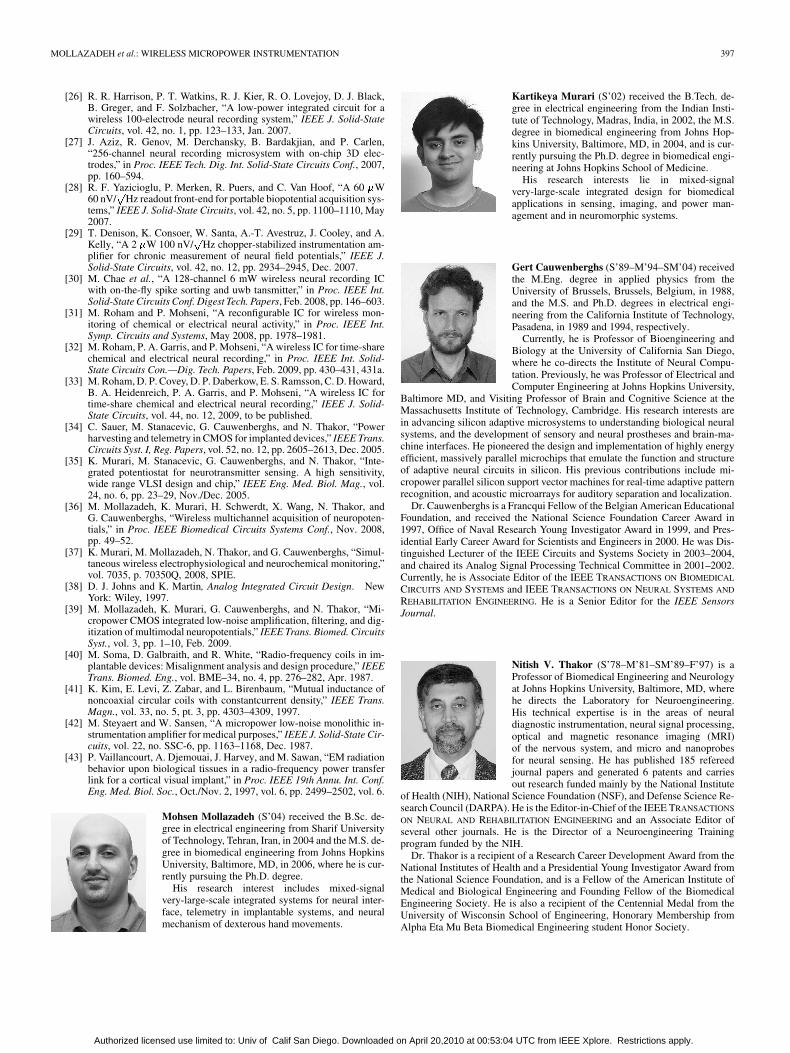
Mohsen Mollazadeh (S’04) received the B.Sc. de-gree in electrical engineering from Sharif Universityof Technology, Tehran, Iran, in 2004 and the M.S. de-gree in biomedical engineering from Johns HopkinsUniversity, Baltimore, MD, in 2006, where he is cur-rently pursuing the Ph.D. degree.
His research interest includes mixed-signalvery-large-scale integrated systems for neural inter-face, telemetry in implantable systems, and neuralmechanism of dexterous hand movements.
Kartikeya Murari (S’02) received the B.Tech. de-gree in electrical engineering from the Indian Insti-tute of Technology, Madras, India, in 2002, the M.S.degree in biomedical engineering from Johns Hop-kins University, Baltimore, MD, in 2004, and is cur-rently pursuing the Ph.D. degree in biomedical engi-neering at Johns Hopkins School of Medicine.
His research interests lie in mixed-signalvery-large-scale integrated design for biomedicalapplications in sensing, imaging, and power man-agement and in neuromorphic systems.
Gert Cauwenberghs (S’89–M’94–SM’04) receivedthe M.Eng. degree in applied physics from theUniversity of Brussels, Brussels, Belgium, in 1988,and the M.S. and Ph.D. degrees in electrical engi-neering from the California Institute of Technology,Pasadena, in 1989 and 1994, respectively.
Currently, he is Professor of Bioengineering andBiology at the University of California San Diego,where he co-directs the Institute of Neural Compu-tation. Previously, he was Professor of Electrical andComputer Engineering at Johns Hopkins University,
Baltimore MD, and Visiting Professor of Brain and Cognitive Science at theMassachusetts Institute of Technology, Cambridge. His research interests arein advancing silicon adaptive microsystems to understanding biological neuralsystems, and the development of sensory and neural prostheses and brain-ma-chine interfaces. He pioneered the design and implementation of highly energyefficient, massively parallel microchips that emulate the function and structureof adaptive neural circuits in silicon. His previous contributions include mi-cropower parallel silicon support vector machines for real-time adaptive patternrecognition, and acoustic microarrays for auditory separation and localization.
Dr. Cauwenberghs is a Francqui Fellow of the Belgian American EducationalFoundation, and received the National Science Foundation Career Award in1997, Office of Naval Research Young Investigator Award in 1999, and Pres-idential Early Career Award for Scientists and Engineers in 2000. He was Dis-tinguished Lecturer of the IEEE Circuits and Systems Society in 2003–2004,and chaired its Analog Signal Processing Technical Committee in 2001–2002.Currently, he is Associate Editor of the IEEE TRANSACTIONS ON BIOMEDICAL
CIRCUITS AND SYSTEMS and IEEE TRANSACTIONS ON NEURAL SYSTEMS AND
REHABILITATION ENGINEERING. He is a Senior Editor for the IEEE SensorsJournal.
Nitish V. Thakor (S’78–M’81–SM’89–F’97) is aProfessor of Biomedical Engineering and Neurologyat Johns Hopkins University, Baltimore, MD, wherehe directs the Laboratory for Neuroengineering.His technical expertise is in the areas of neuraldiagnostic instrumentation, neural signal processing,optical and magnetic resonance imaging (MRI)of the nervous system, and micro and nanoprobesfor neural sensing. He has published 185 refereedjournal papers and generated 6 patents and carriesout research funded mainly by the National Institute
of Health (NIH), National Science Foundation (NSF), and Defense Science Re-search Council (DARPA). He is the Editor-in-Chief of the IEEE TRANSACTIONS
ON NEURAL AND REHABILITATION ENGINEERING and an Associate Editor ofseveral other journals. He is the Director of a Neuroengineering Trainingprogram funded by the NIH.
Dr. Thakor is a recipient of a Research Career Development Award from theNational Institutes of Health and a Presidential Young Investigator Award fromthe National Science Foundation, and is a Fellow of the American Institute ofMedical and Biological Engineering and Founding Fellow of the BiomedicalEngineering Society. He is also a recipient of the Centennial Medal from theUniversity of Wisconsin School of Engineering, Honorary Membership fromAlpha Eta Mu Beta Biomedical Engineering student Honor Society.
Authorized licensed use limited to: Univ of Calif San Diego. Downloaded on April 20,2010 at 00:53:04 UTC from IEEE Xplore. Restrictions apply.