Embed Size (px)
Citation preview

1http://w3.ualg.pt/~jlongras/R/Opto.html
Wireless-photonic-wireless interfaces
based on resonant tunnelling diode
optoelectronic oscillators
José Figueiredoa, C. N. Ironsideb, B. Romeiraa,
T. J. Slightb, L. Wangb and E. Wasigeb,
aCentro de Electrónica, Optoelectrónica e Telecomunicações,
Universidade do Algarve, Campus de Gambelas,
8005-139 Faro, Portugal
bDepartment of Electronics and Electrical Engineering,
University of Glasgow, Glasgow G12 8LT, United Kingdom
http://www.ist-iphobac.org/workshop/

2http://w3.ualg.pt/~jlongras/R/Opto.html
Introduction
We report on novel optoelectronic voltage controlled oscillators (OVCOs)
based on the integration of Resonant Tunneling Diodes (RTDs) with Laser
Diodes (RTD-LDs) and Electro-Absorption Modulators (RTD-EAMs)
When combined they can operate as OVCOs with both optical- and electrical
inputs, and optical- and electrical outputs.
The phase synchronization capability can be used to translate digital
information from the wireless-to-optical domain and from the optical-to-
wireless domain.
3http://w3.ualg.pt/~jlongras/R/Opto.html
Outline
Resonant Tunneling Diode (RTD) operation principle
RTD – electro-absorption modulator (RTD-EAM): operation as a nonlinear
photo-detector (RTD-PD)
Integration of a RTD with a laser diode (RTD-LD)
Optoelectronic voltage controlled oscillator (OVCO): operation as
wireless-photonic-wireless interfaces
Chaos-based optical communication using RTD-LD and RTD-PD circuits
Summary and conclusion
4http://w3.ualg.pt/~jlongras/R/Opto.html
Resonant Tunneling Diode
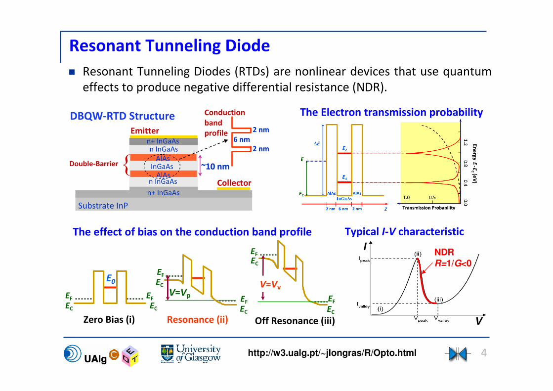
Resonant Tunneling Diodes (RTDs) are nonlinear devices that use quantum
effects to produce negative differential resistance (NDR).
n InGaAs
n InGaAs
Emittern+ InGaAs
Substrate InP
AlAs
AlAsInGaAsDouble-Barrier
n+ InGaAs
Collector
DBQW-RTD Structure
The effect of bias on the conduction band profile
The Electron transmission probability
~10 nm10 nm
Conduction
band
profile
NDRR=1/G<0
Typical I-V characteristic
2 nmnm
2 nmnm
6 nmnm
Zero Bias (i) Off Resonance (iii)Resonance (ii)
E0 V=VvV=VpEF EF
EF
EC EC
EC
EF
EC
EF
EC
EC
EF
I
V

5http://w3.ualg.pt/~jlongras/R/Opto.html
RTD – Electro-absorption modulator (RTD-EAM) Embedding a RTD within an optical waveguide core we obtained an electro-
absorption modulator (RTD-EAM), using Franz-Keldysh or Stark effects.
Wafer structure
Operation as photo-detector (RTD-PD) Optical
waveguide
Current voltage characteristic
+ + +
+
+
hv
n-InGaAlAswaveguide
core
n+ InAlAs
AlAsBarriers
Energy-band diagram
n+ InP
V=VV
V=VVLight outLight out
RF inRF in
Light inLight inLight inLight in
Light inLight inRF outRF out
Built-in amplification regions

6http://w3.ualg.pt/~jlongras/R/Opto.html
Optoelectronic oscillator for photonic systems
Integrating a RTD-EAM with a laser diode it is possible to produce a voltage
controlled oscillator with both optical- and electrical-injection ports, both
optical- and electrical-output ports, and one voltage controlling port.
Light in
Light out
RF in
RF out
Dc bias adjustment
RTD-EAM + LDE
O
E
O
In addition, it is possible to
synchronize or control the
oscillator by both electrical and
optical references or signals.
A close approximation of an ideal oscillator for the photonic systems.

7http://w3.ualg.pt/~jlongras/R/Opto.html
Integration of a RTD with a laser diode
The microwave-photonics interface corresponds to a laser diode (LD)
controlled by a RTD oscillator
RF output
Laser Diode
Au
Printed Circuit Board
Microstrip line
Shunt
Capacitorn
p
RTD Optical Signal
Dc bias + RF signal
Current-voltage (I-V) characteristics
NDRNDR
8http://w3.ualg.pt/~jlongras/R/Opto.html
Optoelectronic voltage controlled oscillator
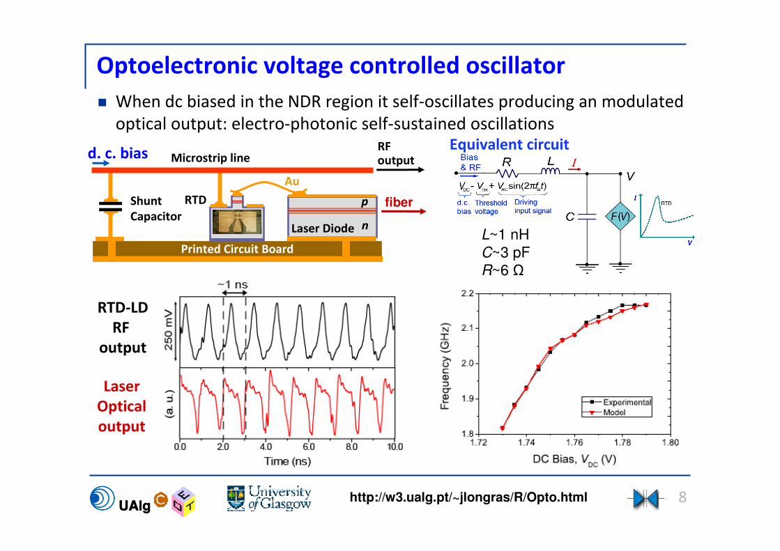
When dc biased in the NDR region it self-oscillates producing an modulated
optical output: electro-photonic self-sustained oscillations
RF output
d. c. bias
Laser Diode
Au
Printed Circuit Board
Microstrip line
Shunt
Capacitorn
pRTD fiber
Laser
Optical
output
RTD-LD
RF
output
L~1 nH
C~3 pF
R~6 Ω
Equivalent circuit
9http://w3.ualg.pt/~jlongras/R/Opto.html
RTD-LD electrical injection locking
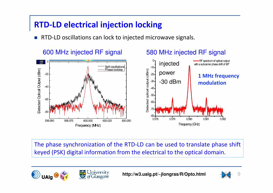
RTD-LD oscillations can lock to injected microwave signals.
1 MHz frequency
modulation
injected
power
-30 dBm
The phase synchronization of the RTD-LD can be used to translate phase shift
keyed (PSK) digital information from the electrical to the optical domain.
600 MHz injected RF signal 580 MHz injected RF signal

10http://w3.ualg.pt/~jlongras/R/Opto.html
RTD-LD as a wireless-to-optical interface
Mobile
terminal
Bias Tee
Patch antenna
Optical Signal
RF
d. c.
bias
RF outputd. c. bias + RF
LD
Printed Circuit Board
Microstrip line
ShuntCapacitor
n
p
RTD Optical
fiber
RTD-LD (E/O Converter)
The RTD-LD responds to the wireless
radiation amplifying it
The laser diode delivers the microwave
detected signal as an optical subcarrier
The interface includes a RTD that amplifies the patch antenna detected
microwave signal and a LD that produces a corresponding optical output.

11http://w3.ualg.pt/~jlongras/R/Opto.html
RTD-EAM/RTD-PD response to optical signals
RTD I-V characteristic and RF injection locking capture level for 1 mW @1550
nm optical signal modulated at 1 GHz (a).
Photo-detected RF power as function of wavelength with DC bias voltage as
parameter for 1.9 mW optical signal modulated at 1 GHz (b).
V=VV
V=VP V=VP
V=VV
When the RTD-PD is DC biased in the NRD region it self-oscillates.

12http://w3.ualg.pt/~jlongras/R/Opto.html
RTD-PD optical injection locking
The RTD-PD follows the phase of the RF optical sub-carrier signal. This behavior
can be used in digital communication schemes including PSK digital modulation
as, for example, in RZ-DPSK.
The photo-generated current is amplified by the NDR, optical locking the
RTD oscillations.
Optical phase-locking
15 kHz frequency modulation
Optical injection locking

13http://w3.ualg.pt/~jlongras/R/Opto.html
RTD-PD as an optical-to-wireless interface
The RTD-LD interface characterization setup includes patch antennas for
directional wireless emission-reception.
Patch antenna
Optical Signal
Bias
Tee
Mobile
terminal
RTD-PD VDC
Optical fiber
Optical
sub-carrier
Light in
RF out
14http://w3.ualg.pt/~jlongras/R/Opto.html
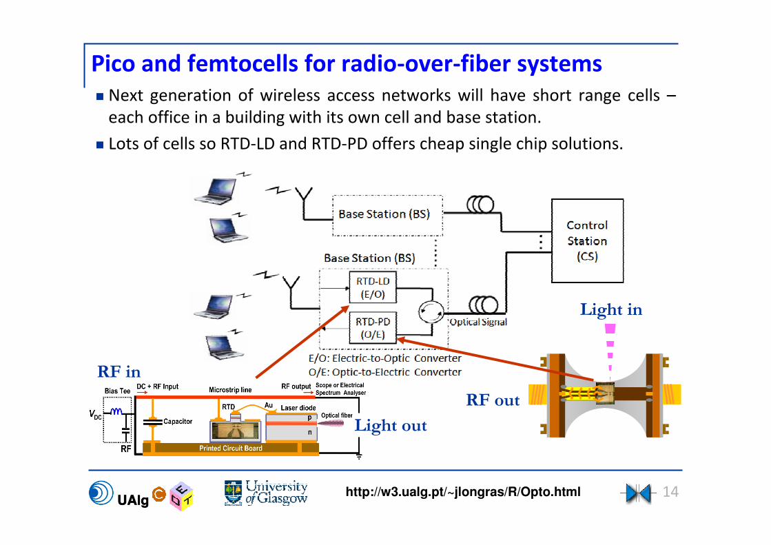
Pico and femtocells for radio-over-fiber systems
Light in
Light out
RF out
RF in
Next generation of wireless access networks will have short range cells –
each office in a building with its own cell and base station.
Lots of cells so RTD-LD and RTD-PD offers cheap single chip solutions.

15http://w3.ualg.pt/~jlongras/R/Opto.html
Chaotic signal generation with the RTD-LD
Chaotic operation with a broadband structure up to a few GHz can be
induced by injected electrical signals.
Electrical output Optical output
16http://w3.ualg.pt/~jlongras/R/Opto.html
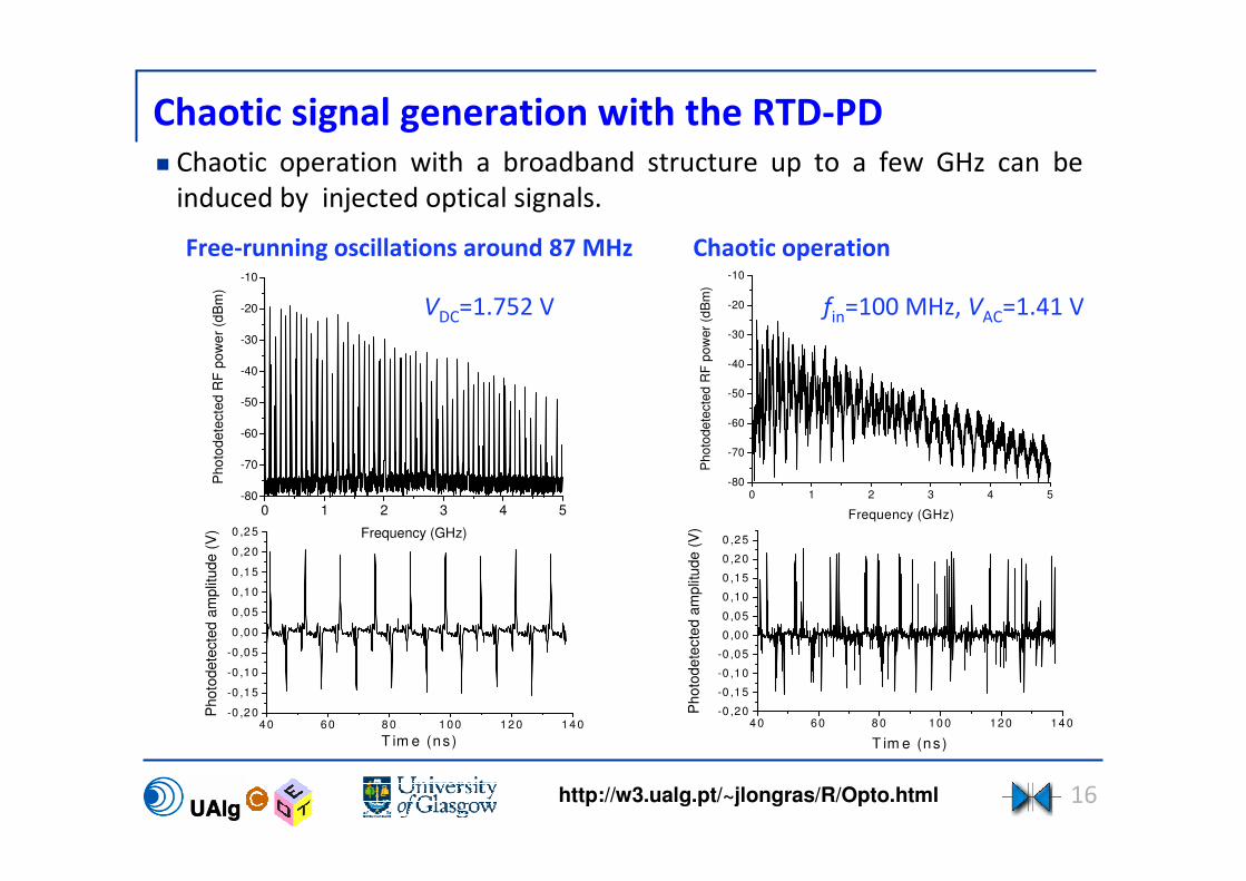
Chaotic signal generation with the RTD-PD Chaotic operation with a broadband structure up to a few GHz can be
induced by injected optical signals.
0 1 2 3 4 5-80
-70
-60
-50
-40
-30
-20
-10
Ph
oto
de
tecte
d R
F p
ow
er
(dB
m)
Frequency (GHz)0 1 2 3 4 5-80
-70
-60
-50
-40
-30
-20
-10
Pho
todete
cte
d R
F p
ow
er
(dB
m)
Frequency (GHz)
Free-running oscillations around 87 MHz
4 0 60 8 0 10 0 120 14 0-0 ,20
-0 ,15
-0 ,10
-0 ,05
0 ,00
0 ,05
0 ,10
0 ,15
0 ,20
0 ,25
Ph
oto
de
tecte
d a
mp
litu
de
(V
)
T im e (ns)
40 60 8 0 1 00 12 0 14 0-0 ,2 0
-0 ,1 5
-0 ,1 0
-0 ,0 5
0 ,0 0
0 ,0 5
0 ,1 0
0 ,1 5
0 ,2 0
0 ,2 5
Photo
dete
cte
d a
mplit
ude (
V)
T im e (ns)
Chaotic operation
fin=100 MHz, VAC=1.41 V VDC=1.752 V

17http://w3.ualg.pt/~jlongras/R/Opto.html
RTD chaos-based optical communication link
An incoming RF signal can be encrypted at the physical level using a RTD-
LD and decrypted using a PD-RTD
Optical
fiber
Message(sound, video, data)
Original electrical signal
Message(sound, video, data)
Signal transmitted
PD-RTD
PD
tV
RTD-LD (chaos generator)
t
Electrical signal
V
Subtractionunit
coupler
(chaos generator)

18http://w3.ualg.pt/~jlongras/R/Opto.html
Summary and Conclusion
Demonstration of RTD-LD hybrid integration using separated chips, although
monolithic integration of a RTD-LD has been previously demonstrated, that
can operate as optoelectronic voltage controlled oscillators.
Modulation of the phase of the radio frequency sub-carrier was
demonstrated in the laser output.
First demonstration of wireless to optical conversion using synchronization
of a nonlinear oscillator.
Demonstration of RTD-PD that can operate as a microwave oscillator
controlled by light-wave subcarriers.
The RTD-LD and RTD-PD applications include: single chip platform with
reduced size for low cost microwave/photonics devices.
Other potential applications are in chaos-based communications, radio-over-
fibre systems, clock recovery, etc.
This technology can be extend to higher frequencies (tens of GHz)


![Lesson2 - University of Notre Damecpoellab/teaching/cse40814_fall08/Lesson2.pdfmodulation with a carrier frequency for transmission (analog signal!) f [Hz] ... ASK, FSK, PSK - main](https://img.pdfslide.net/doc/110x75/5e7b00ef273ebc401856cc12/lesson2-university-of-notre-cpoellabteachingcse40814fall08lesson2pdf-modulation.jpg)