Embed Size (px)
Citation preview
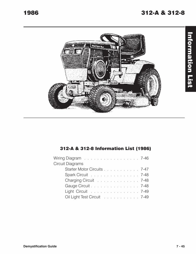
312-A & 312-8 Information List (1986)
Wiring Diagram . . . . . . . . . . . . . . . . . 7-46
Circuit Diagrams
Starter Motor Circuits . . . . . . . . . . . 7-47
Spark Circuit . . . . . . . . . . . . . . . 7-48
Charging Circuit . . . . . . . . . . . . . 7-48
Gauge Circuit . . . . . . . . . . . . . . . 7-48
Light Circuit . . . . . . . . . . . . . . . 7-49
Oil Light Test Circuit . . . . . . . . . . . 7-49
Info
rma
tion
Lis
t1986 312-A & 312-8
Demystification Guide 7 - 45
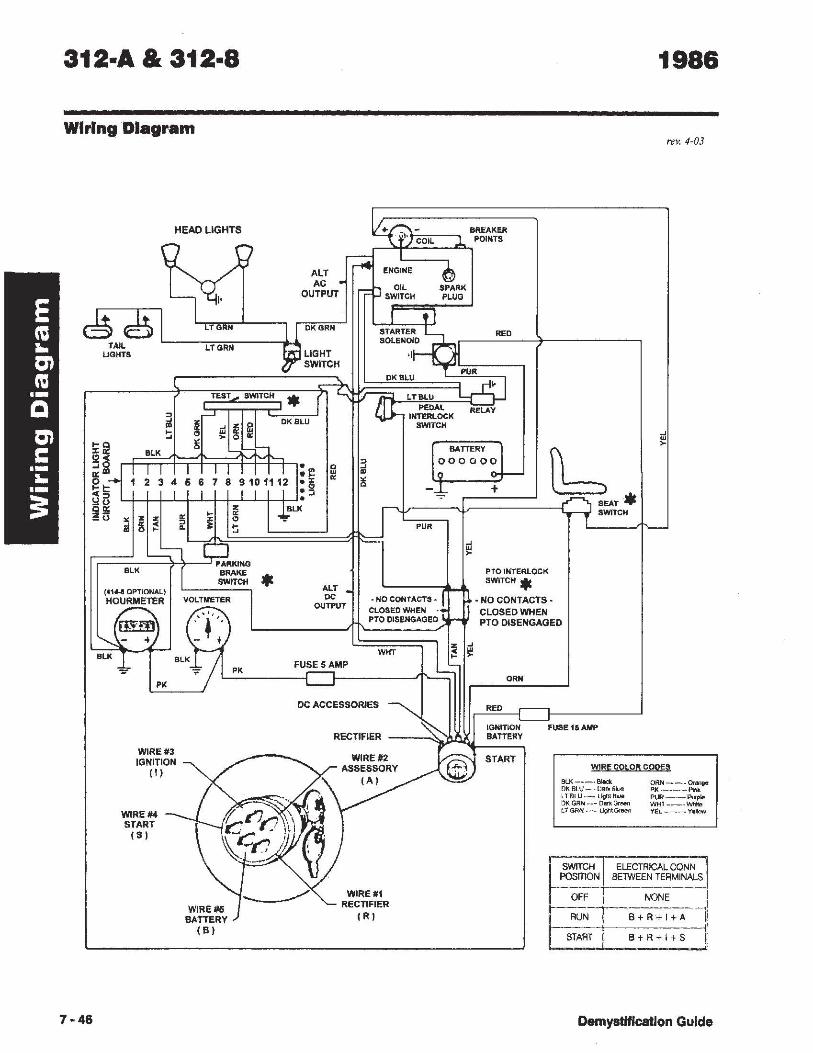
312·A & 312·8
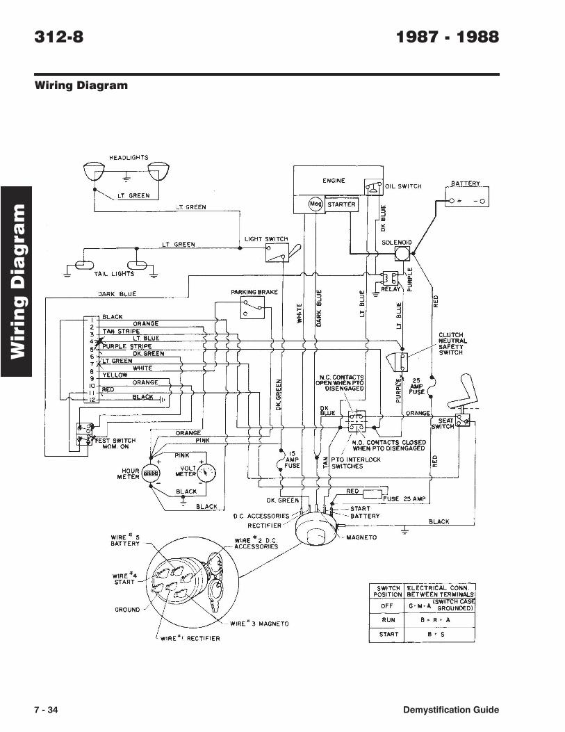
WIring Diagram
HEADLIGHTS
I'
lTGRN
LTGRN
TEST SWITCH
" ~ ~ .. " ~ ~ ~ 0
~ > 0
BLK
r;::==::,,--==~~-~ PARKING BlK BRAKE
7·46
SWITCH * (.1'~ OPTIONAL) HOURMETER lJOL. TMETER
PK
WIRE #3 IGNITION
II)
WIRE #4 START IS)
WIRE #5 BATTERY
IB)
PK
ALT AC
OUTPUT
DKGRN
LIGHT SWITCH
* DKSLU
0 Q
oJ! w .x ~
.S! ~ •
BREAKER POINTS
rL~
RED
LTBLU
PEDAL RELAY INTERLOCK
SWITCH
BAnERY
000000
PUR
+
PTO INTERLOCK
SWITCH *
b SEAT * SWITCH
1986
rev. 4-03
ALT DC
OUTPUT • NO CONTACTS·
CLOSED WHEN • PTO DISENGAGED
• NO CONTACTS· CLOSED WHEN PTO DISENGAGED
WHT
FUSE5AMP
ORN
OC ACCESSORIES RED
IGNITION
RECTIFIER --_"1~b),~~B~A~TT~E~R~Y
WIRE #2 ASSESSORY
IA)
WlRE.1 RECTIFIER
IR)
START
FUSE 16 AMP
WIRE COLOR CODES
BLK.-"'_", B*'k DK SLV •• ,' Dark 9lu!I LT'BLU .. ,_ Ugrnlllue DK GRN ___ Dm. Green U ~N .. _. L~t Gfa"",
ORN _.,,_ .. 0rM0e f'I(._, .. _._PinIt. PUR ,_.,_ Purplll WHI_·· __ WI'IiIe
'1'101.·· .. _ · - _ '1'.""""
~"';-CHT ELECTRICAL CONN
POSITION I BElWEEN TERMINALS ----r--------
OFF i NONE j------1--·-·---·--·--· ~ RUN B+R+I+A r-~---+-------·--· ~~AT! B+R+I+S
Demystlflcatlon Guide
Circ
uits
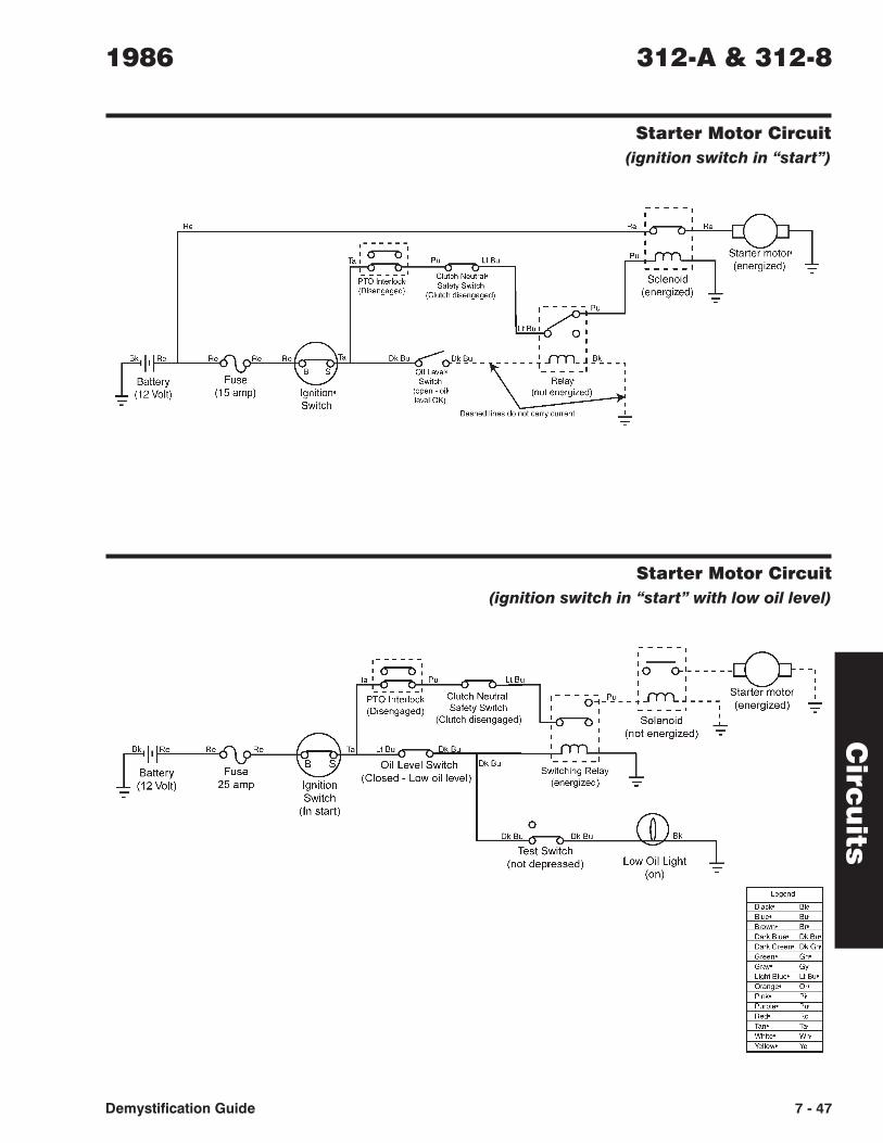
Starter Motor Circuit
(ignition switch in “start”)
Starter Motor Circuit
(ignition switch in “start” with low oil level)
1986 312-A & 312-8
Demystification Guide 7 - 47
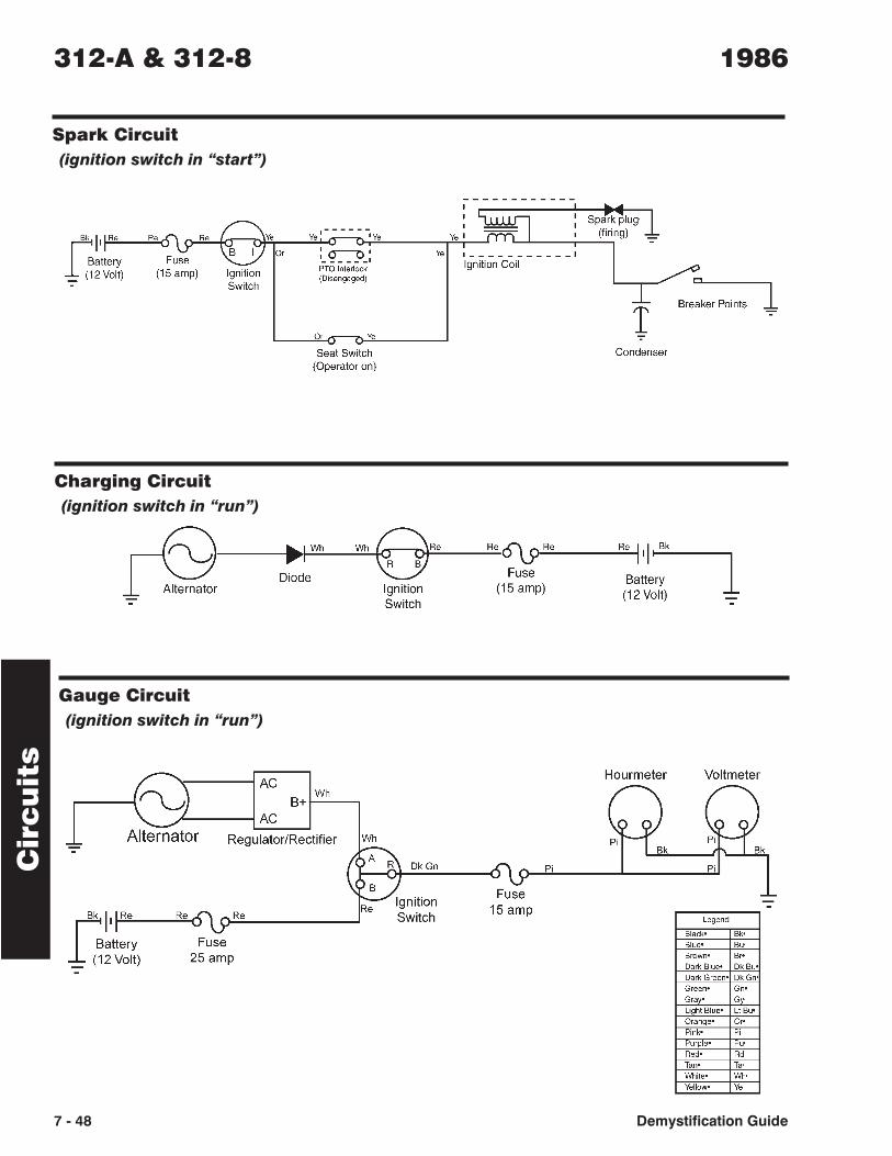
Gauge Circuit
(ignition switch in “run”)
Cir
cu
its
Spark Circuit
(ignition switch in “start”)
Charging Circuit
(ignition switch in “run”)
312-A & 312-8 1986
7 - 48 Demystification Guide
Circ
uits
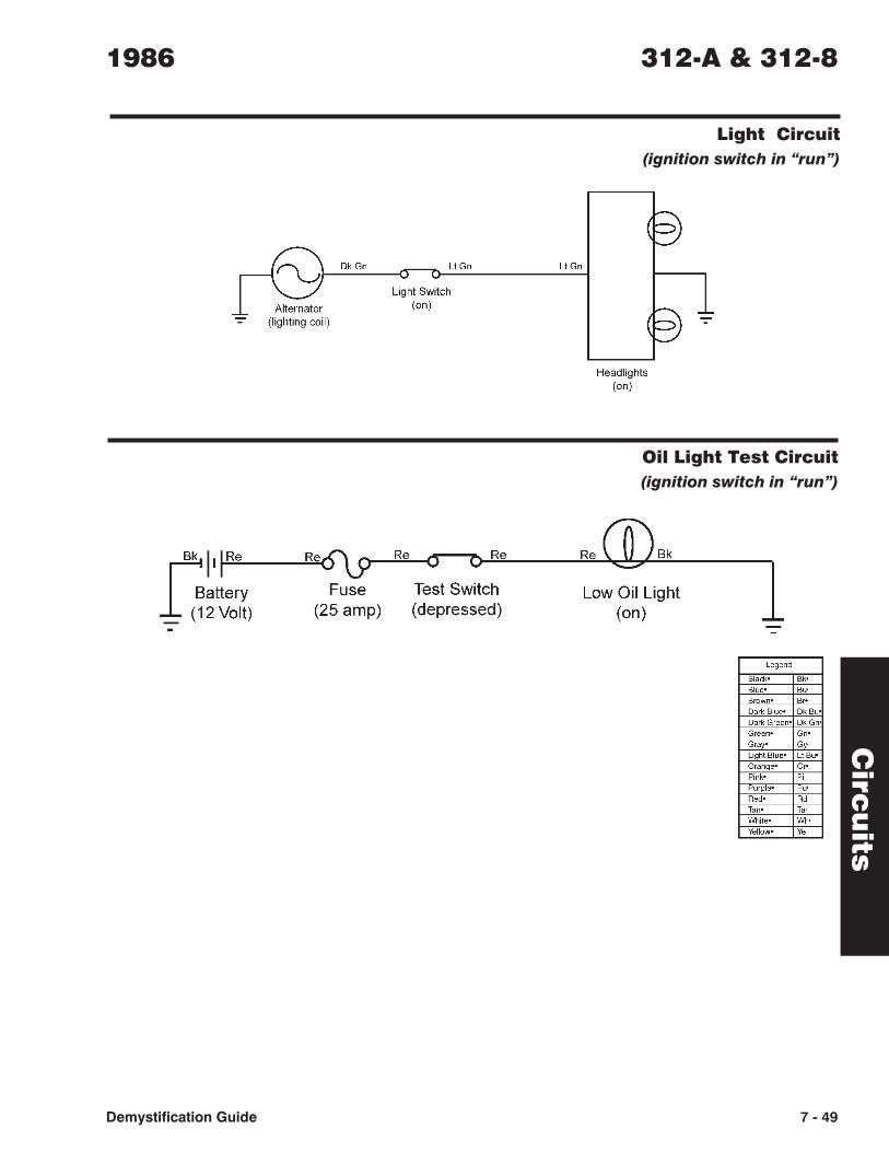
Light Circuit
(ignition switch in “run”)
Oil Light Test Circuit
(ignition switch in “run”)
1986 312-A & 312-8
Demystification Guide 7 - 49

312-8 Information List (1987 - 1988)
Wiring Diagram . . . . . . . . . . . . . . . . . 7-34
Circuit Diagrams
Starter Motor Circuit . . . . . . . . . . . 7-35
Spark Circuit . . . . . . . . . . . . . . . 7-35
Charging Circuit . . . . . . . . . . . . . 7-36
Gauge Circuit . . . . . . . . . . . . . . . 7-36
Light Circuit . . . . . . . . . . . . . . . . 7-36
Oil Circuit . . . . . . . . . . . . . . . . . 7-37
Info
rma
tion
Lis
t1987 - 1988 312-8
Demystification Guide 7 - 33
Wiring Diagram
Wir
ing
Dia
gra
m312-8 1987 - 1988
7 - 34 Demystification Guide
HEADLIGHTS
v -,1. "- ENGINE r?ir ~ OIL SWITCH BATTERY
LT GREEN -ol LT GREEN MOQ STARTERl + ...
:;) ...J CD
" 0
LT GREEN LlGHT~ SOLENOID
TAIL LlGH~ [ -=-
... I~ \...J
Q. It:
DARK BLUE 13'" RELAY
:;) ... ... Q. :;) :> -=-...J ...J
0 ... CD CD ... \oJ
r--"[ BLACK .... :;) It:
I :.< ':i ...J a:: CD
2 ORANGE l ~ «
TAN STRIPE l., 0 :i
3 4-
.., LT BLUE CLUTCH
5 'PURPLE STRIPE
~ 1/ NEUTRAL
6 OK. GREEN SAFETY
7 • 'LT. GREEN SWITCH
B \ WHITE
9 YELLOW
10 ORANGE z N.C. CONTACTS ~~. 25
.-- REO \oJ OPEN WHEN PTO
II RI A K
... DISENGAGED Q. AMP: (
c.R 1'1 I a::
~ ~ FUSE
(!)
>i Q.
~J 0 ~/1;E ORANGE
--r.
~iRJ SE~1 ORANGE r
SWITCH
l!.-lf'EST SWITCH Il~ PINK / / N ~ CONTACTS CLOSED
L- MOM. ON
~
""~ 15 .J
/ WHEN PTO DISENGAGED
+ + AMP ~ PTO INTERLOCK 0
VOLT, ". FUSE \oJ
HOUR .... SWITCHES 0::
METER miIiIi METER ~\ .
- (' (
BLACK r )~~ED~USE ~ BLACK OK. GREEN 25 AMP I
START D.C. ACCESSORIES -S0 BATTERY
RECTIFIER ./ BLACK
WIRE'* 5 - WIRE '* 2 D.C.
, ~ BATTERY
MAGNETO
ACCESSORIES
k;~~~/f WIRE#4 .' .Jtt1 \ ~ START' -1'~$ u0 ~ SWITCH ELECTRICAL CONN,
~ POSITION BETWEEN TERMINALS
GROUND J OFF G M A (SWITCH CASI •• GROUNDED)
-- WIRE· 3 MAGNETO RUN B. R' A
. WIRE I RECTIFIER START B' S
Circ
uits
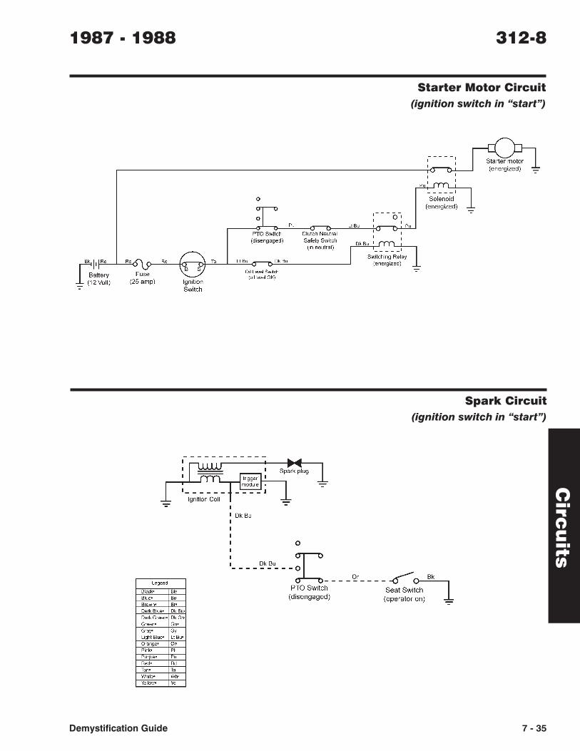
Starter Motor Circuit
(ignition switch in “start”)
Spark Circuit
(ignition switch in “start”)
1987 - 1988 312-8
Demystification Guide 7 - 35
Cir
cu
its
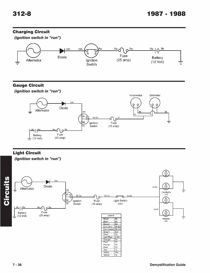
Gauge Circuit
(ignition switch in “run”)
Light Circuit
(ignition switch in “run”)
Charging Circuit
(ignition switch in “run”)
312-8 1987 - 1988
7 - 36 Demystification Guide
Circ
uits
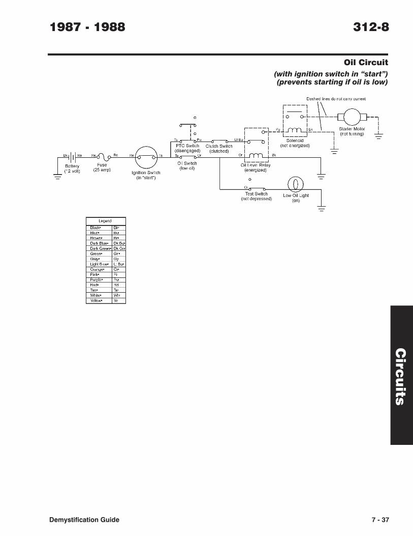
Oil Circuit
(with ignition switch in “start”)(prevents starting if oil is low)
1987 - 1988 312-8
Demystification Guide 7 - 37
fik II Re
Battery _ (12volt)
Fuse (25 amp)
Ignition Switch (In "start")
o
~ I 1 0
Clutch Switch (clutched)
Dashed lines
1 -- 1
1----' ~\ do not carry current
I 0 0-1-- -c(P r---- I I ---I o-L PUol I -
U", , ' -- l1YrL.J" - 'I I ____ --- Starter Motor
: : '" So,'""" - 1 ,""",m,"" 1-Or 1 ot energized) 1 -=
L Bk ---1-
OiILe~8IRe~Y (energized)
o
Or
Test Switch (not depressed)
Low Oil Light (on)

312-8 Information List (1989)
Wiring Diagram . . . . . . . . . . . . . . . . . 7-28
Circuit Diagrams
Starter Motor Circuit . . . . . . . . . . . 7-29
Spark Circuit . . . . . . . . . . . . . . . 7-29
Gauge Circuit . . . . . . . . . . . . . . . 7-30
Charging Circuit . . . . . . . . . . . . . . 7-30
Light Circuit . . . . . . . . . . . . . . . . 7-30
Oil Circuit . . . . . . . . . . . . . . . . . 7-31
Info
rma
tion
Lis
t1989 312-8
Demystification Guide 7 - 27
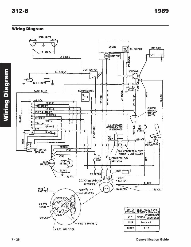
Wiring Diagram
Wir
ing
Dia
gra
m312-8 1989
7 - 28 Demystification Guide
HEADLIGHTS
y + \. ENGINE
~ '" LT. GREEN
OIL SWITCH BATTERY
-91 LT. GREEN 8 [STARTER + I&J
3 -*" CD
~
LT. GREEN LIGHTg SOLENOID
'AIL LIGH~ ";" \..../ \~ '\ ":" '-'
DARK BLUE PAR~RAKE I&J I&J RELAY ~ 3 3 ";" 0
'--0 ~ III CD I&J ~ 1£
j.Bl.ACK :I u
0 i ~ ~ OIl
L....- ei: :oJ III oJ
2 ORANGE • ot CD
3 ~AN STRIPE L 0 !j
4 TI8lUE ( 1- CLUTCH
II PURPLE STRIPE
1r NEUTRAL
IS 6 OK,GREEN SAFETY
C[ 7 LT, GREEN SWITCH
ii 8 WHITE 9 YELLOW 10 ORANGE z N,C, CONTACT8 I&J 211
..-- II RED 11/ OPENWHENPT ..J
BLACK 'I 11/ DISENGAGED A. AMP
,~ II:
~~E 1; II: FUSE
L..I.&.J ,,1 " :> ':II. A. 0
~ ~tJ ORANGE --
'" t~ SE~~
ORANGE SWITCH
.... "-- TEST SWITCH
I/~ PINK 7 /.,:: ''''''M''SCII''ED MOM, ON
If" ""' :$ ?I" WHEN PTO DISENGAGED
+ VOLT \.,
AMP ~ PTO INTERLOCK 0
HOUR FUSE I&J
METER imJl METER' , .. SWITCHES II:
- I ( BLACK r .f RED-c::jJ
~ DK.GREEN BLACK ..! -START
D.C. ACCESSOR:~ ~ BATTERY
REt''"'' ~A~\ BLACK
WIRE:!! II - -t BATTERY WIRE *2 DC. I~MAGNETO BLACK
ACCESSORIES -~f ~~~ ,\
WIRE#4 H :0f ~ START-1 (1
~ SWITCH ELECTRICAL CONN.
~ tJ POSITION BETWEEN TERMINALS
GROUND OFF ,TSWITCH CASE
G· M' A GROUNDED)
WIRE I 3 MAGNETO RUN B·R+A
• WIRE I RECTIFIER START B + 5
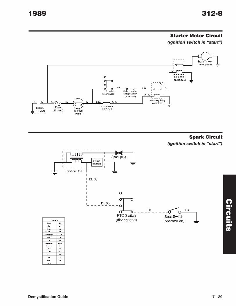
Starter Motor Circuit
(ignition switch in “start”)
Spark Circuit
(ignition switch in “start”)
!"!#$
%&'() %)
%&*! %*
%+,-# %+
.'+) %&*! .) %*
.'+) /+!!# .) /#
/+!!# /#
/+'0 /0
1"23 %&*! 3 %*
4+'#"! 4+
51#) 51
5*+6&! 5*
7!$ 7$
8'# 8'
9213! 92
:!&&,- :!
Circ
uits
1989 312-8
Demystification Guide 7 - 29
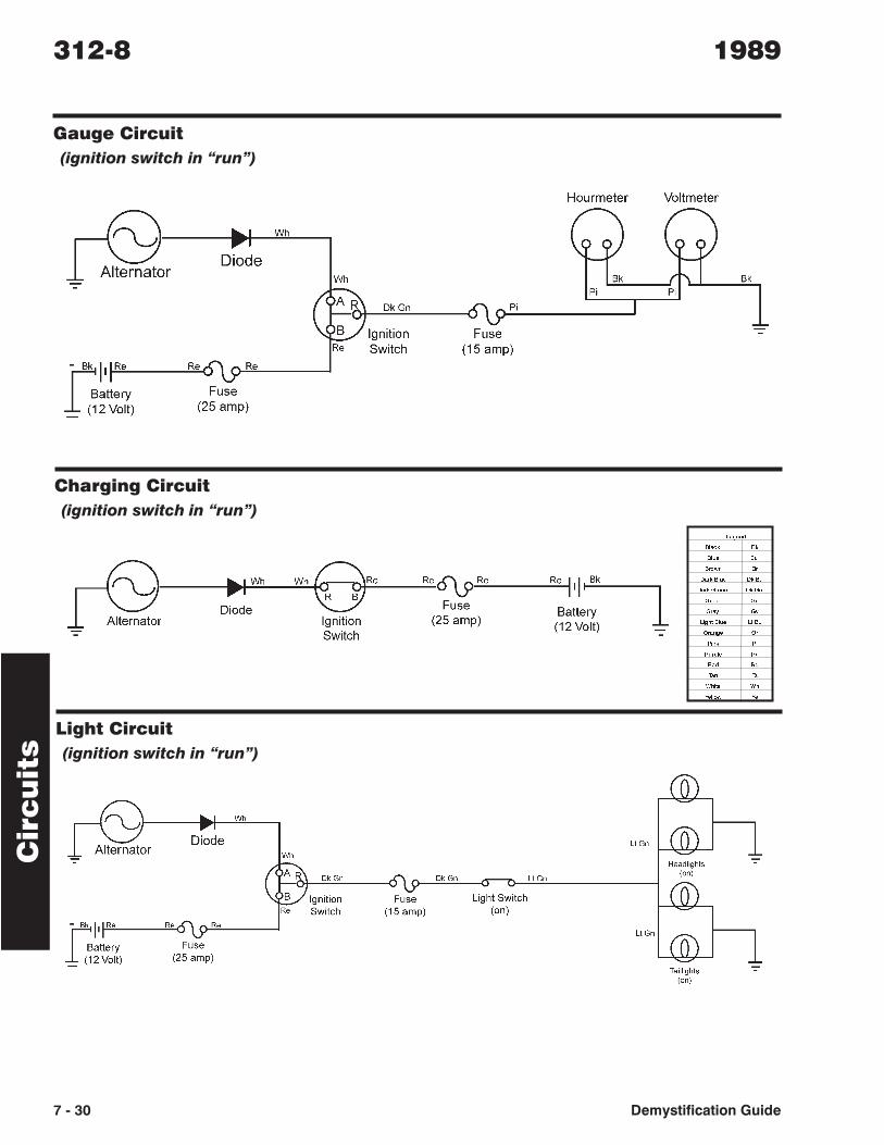
Gauge Circuit
(ignition switch in “run”)
Charging Circuit
(ignition switch in “run”)
Light Circuit
(ignition switch in “run”)
!"!#$
%&'() %)
%&*! %*
%+,-# %+
.'+) %&*! .) %*
.'+) /+!!# .) /#
/+!!# /#
/+'0 /0
1"23 %&*! 3 %*
4+'#"! 4+
51#) 51
5*+6&! 5*
7!$ 7$
8'# 8'
9213! 92
:!&&,- :!
Cir
cu
its
312-8 1989
7 - 30 Demystification Guide
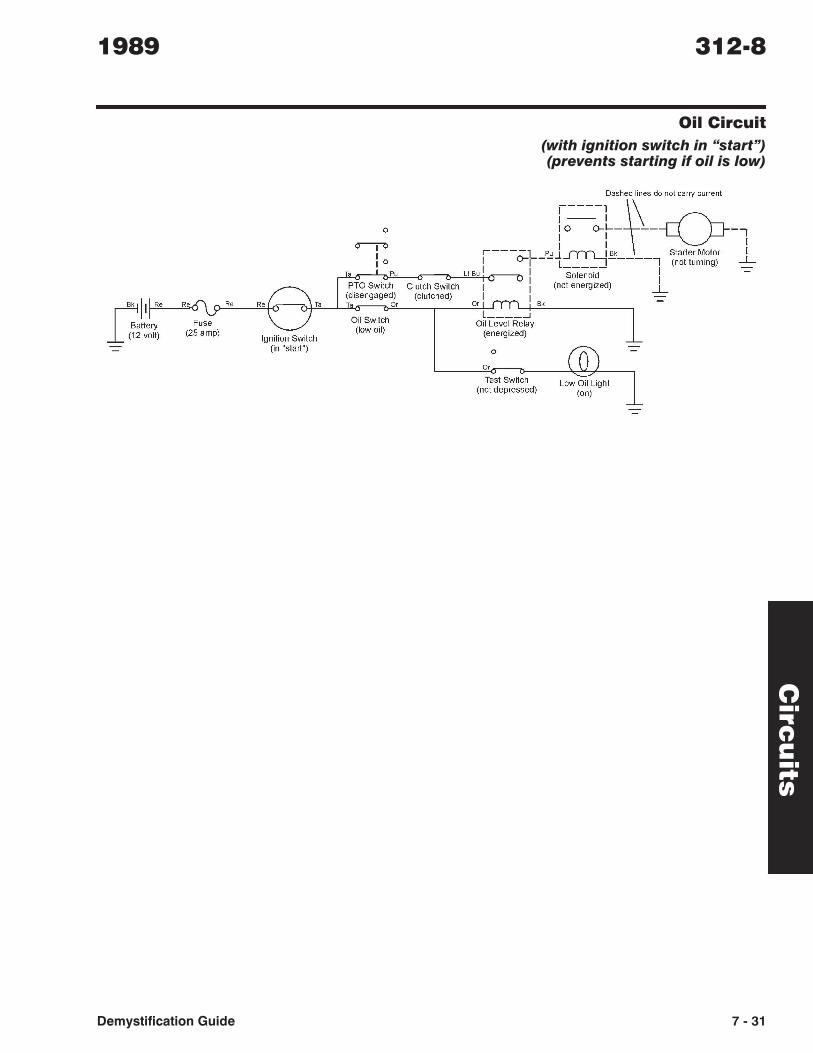
Oil Circuit
(with ignition switch in “start”)(prevents starting if oil is low)
Circ
uits
1989 312-8
Demystification Guide 7 - 31
Dkl' Re
Battery _ (12volt)
~ lo ___ ~L~h~ed\es do-c(P not carry current
'" ' 0 r---- I I ---'" I oJ- '"" I --,::,~,;::g::) """ I I -- l~"---- ru""" """ I '-'t-"'-_LJl':..a",~.:: ~ I I, "'''''0 I ""'m,"" ~ Oil SwitC:;:h----,-...:...-- (O)rr : I I not energized) I -= ,b,,") l' -"-OiILe~8IRe~
Ignition Switch (In "start")
(energized) Y
o
Or
Test Switch (not depressed)

312-H & 312-8 Information List (1990 - 1991)
Wiring Diagram . . . . . . . . . . . . . . . . . 7-40
Circuit Diagrams
Starter Motor Circuits . . . . . . . . . . . 7-41
Spark Circuit . . . . . . . . . . . . . . . 7-42
Charging Circuit . . . . . . . . . . . . . 7-42
Gauge Circuit . . . . . . . . . . . . . . . 7-42
Light Circuit . . . . . . . . . . . . . . . 7-43
Info
rma
tion
Lis
t1990 - 1991 312-H & 312-8
Demystification Guide 7 - 39
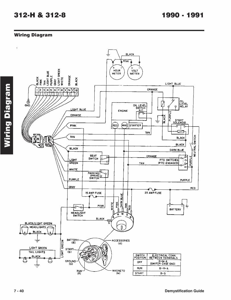
Wiring Diagram
Wir
ing
Dia
gra
m312-H & 312-8 1990 - 1991
7 - 40 Demystification Guide
HEADLIGHT SWITCH
15 AMP FUSE
PINK
BLACK
G
ACCESSORIES (AI
MAGNETO (M)
TAN
OFF
RUN
START
LIGHT BLUE
25 AMP FUSE
G+M'A (SWITCH CASE GND)
B'S
PURPLE
RED
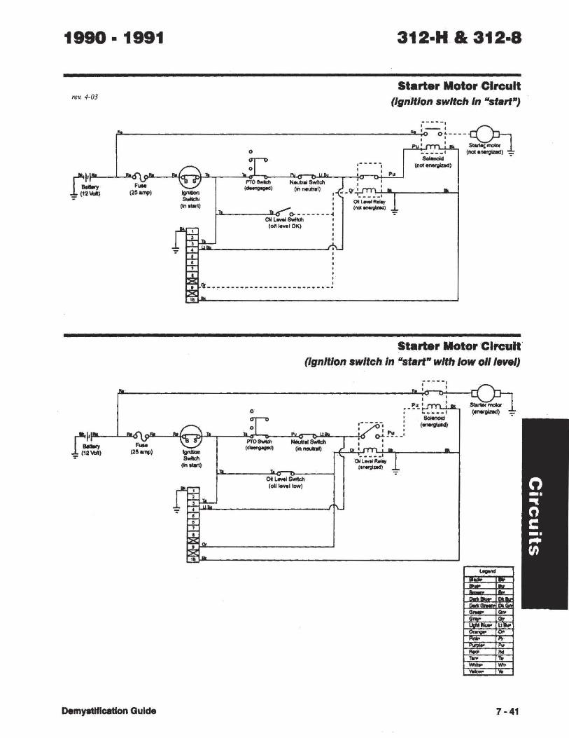
1990· 1991
Te V, 4-03
312·H & 312·8
Start.r Motor CircuIt (Ignition switch In "start")
(£-_________________ ~:----;L---~ , ' I I ~mob
o _ ........ 1 (naul'lltfVladl _
Demy.tJtlCllllon GuIde
-..... (n.-ll
o
1'0'0_ (~) ........ -
(In-neutral )
C>-~------4 ow L.wISwItdl ,
(011 leY.' OK) I
,~-----.-----------------.-!
......... . (not'~)
.,.
Starter Motor Circuit (Ignition switch In "start" with low ollie"")
o
OI~G:WIkh (011 ...... I/ow)
.,.
i .. · .... -' , ' ,
... ~LI_ ' , .. __ .-, ........ (-
7-41
Cir
cu
its
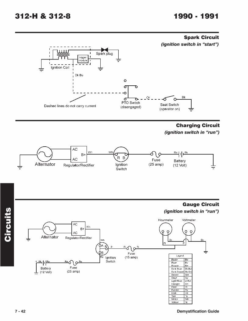
Spark Circuit
(ignition switch in “start”)
Charging Circuit
(ignition switch in “run”)
Gauge Circuit
(ignition switch in “run”)
312-H & 312-8 1990 - 1991
7 - 42 Demystification Guide
Circ
uits
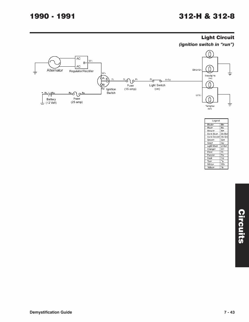
Light Circuit
(ignition switch in “run”)
1990 - 1991 312-H & 312-8
Demystification Guide 7 - 43
~------IAC
AC
Wh B+t----,
Regulator/Rectifier Wh
Re Ignition - Bk III-!R~e,--___ ....!R~e'-O o-""Re"--___ ---l Switch
r=:attery 1 (~2VOlt) Fuse
(25 amp)
Pi Pi
Light Switch (on)
Lt Gn
Bk/Lt Gn 1-~u.."L-...J
Lt Gn
Taillightsl (on)
Legend
Black'
Blue' Brown-Dark Blue'
Dark Green'
Green-
Gray·
Light Blue'
Orange· Pink-
Purple'
Red' Tan-White'
Yellow'
Bk' Bu-
B" DkBu'
DkGn'
Gn'
Gy
Lt Bu'
Or· Pi-
Pu-
Rd
Ta-Who
Ye
rev. 4-03
7 - 23Demystification Guide
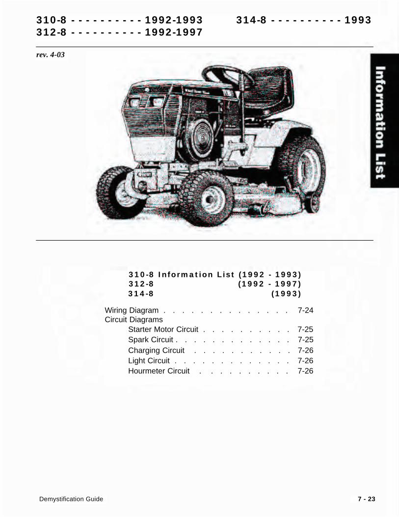
310-8 Information List (1992 - 1993)
312-8 Information List (1992 - 1997)
314-8 Information List 1992 (1993)
Wiring Diagram . . . . . . . . . . . . . . 7-24
Circuit Diagrams
Starter Motor Circuit . . . . . . . . . . 7-25
Spark Circuit . . . . . . . . . . . . . 7-25
Charging Circuit . . . . . . . . . . . 7-26
Light Circuit . . . . . . . . . . . . . 7-26
Hourmeter Circuit . . . . . . . . . . 7-26
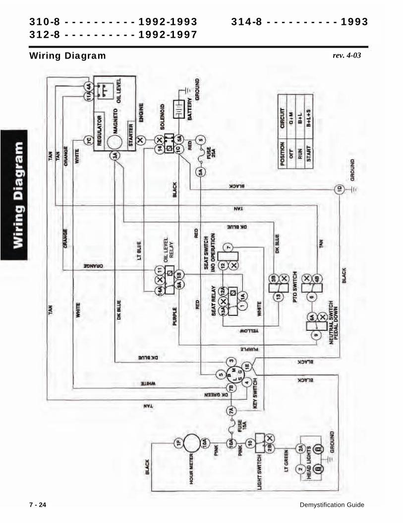
310-8 - - - - - - - - - - 1992-1993 314-8 - - - - - - - - - - 1993
312-8 - - - - - - - - - - 1992-1997
310-8 - - - - - - - - - - 1992-1993 314-8 - - - - - - - - - - 1993
312-8 - - - - - - - - - - 1992-1997
Wiring Diagram rev. 4-03
7 - 24 Demystification Guide
i
rev. 4-03
7 - 25Demystification Guide
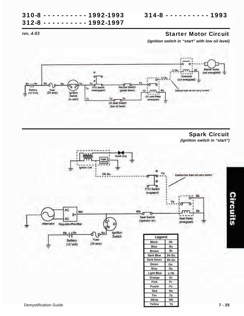
Starter Motor Circuit(ignition switch in “start” with low oil level)
Spark Circuit(ignition switch in “start”)
310-8 - - - - - - - - - - 1992-1993 314-8 - - - - - - - - - - 1993
312-8 - - - - - - - - - - 1992-1997
rev. 4-03
7 - 26 Demystification Guide
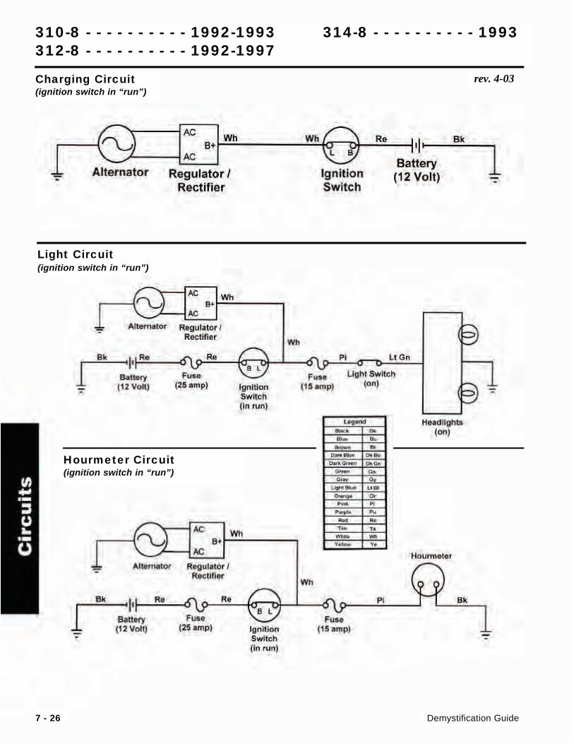
Charging Circuit(ignition switch in “run”)
Light Circuit(ignition switch in “run”)
Hourmeter Circuit(ignition switch in “run”)
310-8 - - - - - - - - - - 1992-1993 314-8 - - - - - - - - - - 1993
312-8 - - - - - - - - - - 1992-1997
312-8 Information List (1998)
Wiring Diagram . . . . . . . . . . . . . . . . . 7-18
Circuit Diagrams
Starter Motor Circuit . . . . . . . . . . . 7-19
Spark Circuits . . . . . . . . . . 7-19 & 7-20
Charging Circuit . . . . . . . . . . . . . 7-20
Hourmeter Circuit . . . . . . . . . . . . 7-20
Light Circuit . . . . . . . . . . . . . . . 7-21
Info
rma
tion
Lis
t1998 312-8
Demystification Guide 7 - 17
.... ... CD
I g
~
TOHEADUGHr ......... "",",METER
.. ~ "'''ITlW.
~
52 PTO
F4
'"
CI.DSED 'MEN PTO IS..........,."
.v;
I I ~lW. r:r~' I I RElAY)
L::LJ J 51
~~ OPERATOR PftESENT
r:roi' I
L· 1.' I I IKll. rELAy)
G -J
r::r1,
I' • I
~ur:.r£LAtt -J ~ I
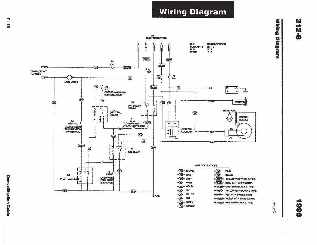
Wiring Diagram
.. --
,,:,"GND
F1 ...
OfF ...........,.. .... STAAT
NO ""'"'"""'" IIAL B'. B"
B+ I ~ ~I OJ,
r---~---mAA' I~~
ill -
IGH1ION MOOUlE
~I RfG-O:@
WIRE 00UlR COOES
-<iitoo(i)o SUE
~GR£Y o@o Mm o(iijoYlClEr -®- ... oG)o VEllDW oG)o , .... -<iito ..... o(Qio """"""
W PINK o@- lUCK
~ GRfSoI WITH,...,.SllIft
-<iiiiit- BUJE WITH ~S1N'E ~ GREY WITH III.ACI(.STHIPE
~ vruowlMTli BlN::I( ST8IPE
-<Mir REO WITH ,...,. STRIPE
~ Vk)lEfWITH WHIlE STRIPE
~ PJ« WJTH BlACK STRIPE
! :z. i 2 • III ;
<1 < i' :::
a
w ... N • CD
... i
Circ
uits
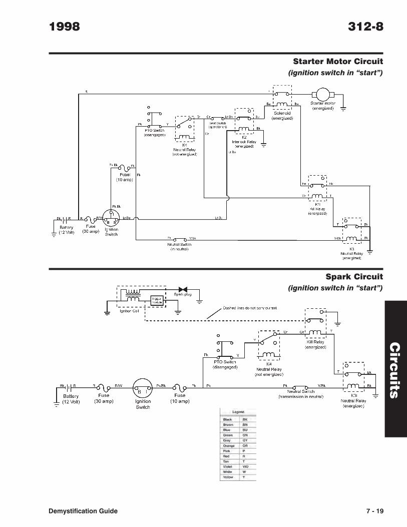
Starter Motor Circuit
(ignition switch in “start”)
Spark Circuit
(ignition switch in “start”)
1998 312-8
Demystification Guide 7 - 19
Cir
cu
its
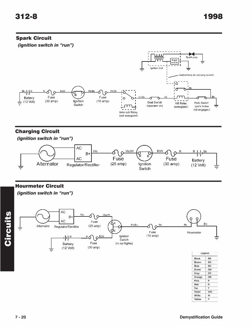
Spark Circuit
(ignition switch in “run”)
Charging Circuit
(ignition switch in “run”)
Hourmeter Circuit
(ignition switch in “run”)
312-8 1998
7 - 20 Demystification Guide
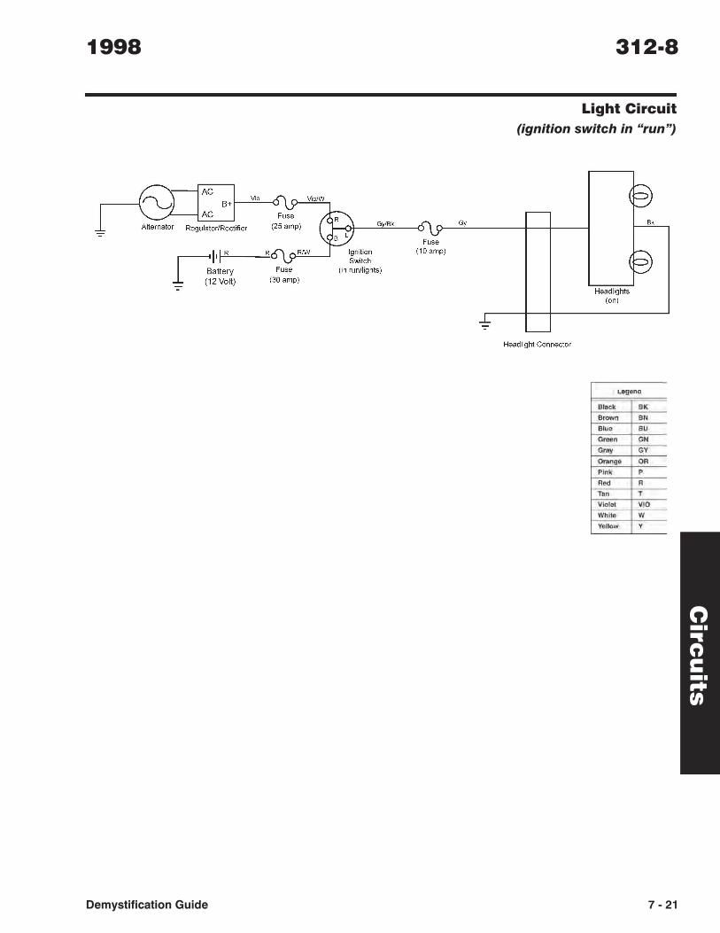
Light Circuit
(ignition switch in “run”)
Circ
uits
1998 312-8
Demystification Guide 7 - 21
AC B+ I-_V~i.::.o_-O
AC
Regulator/Rectifier
~ II 1-'-'-1 R ---:.;,R6\9 RIW
Battery Fuse _ (12 Volt) (30 amp)
Gy/Bk
Fuse (10amp)
Gy
Headlight Connector
Headlights (on)
U'U""",1
Slack BK
Browl1 BN
SlUG BU
Green GN
Gray GY Orange OR
Pink P
Red R
IlIn ,. Vlolel VlO Whit .. W
Yellow V
7 - 22EDemystification Guide
1999 - 2001 312-8
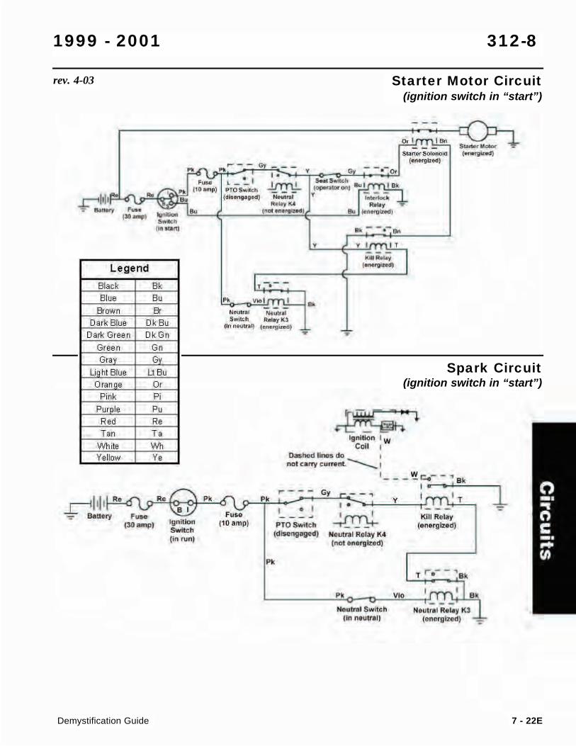
Starter Motor Circuit(ignition switch in “start”)
rev. 4-03
Spark Circuit(ignition switch in “start”)
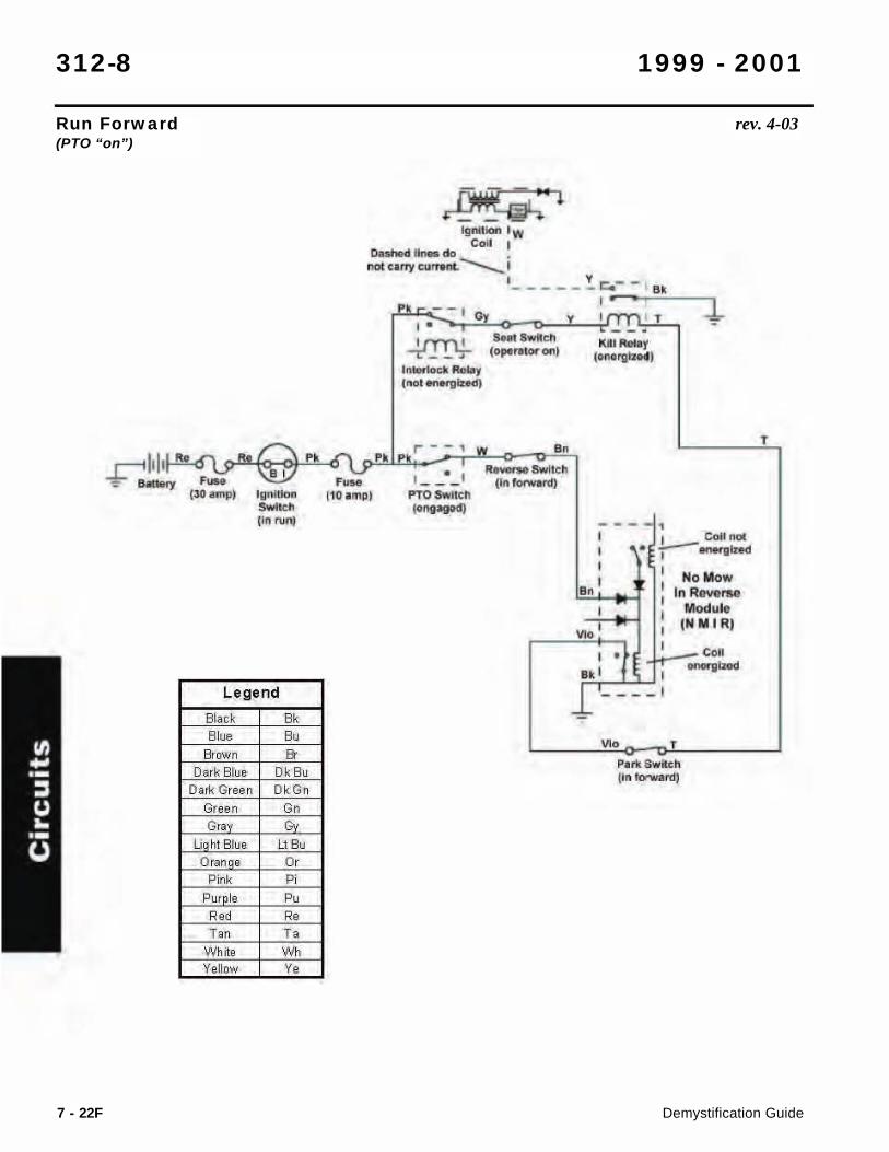
Run Forward(PTO “on”)
312-8 1999 - 2001
Demystification Guide7 - 22F
rev. 4-03
. r'\ '" "~ .QY .... (30 , mpl ,,.-.J;:";hl - ,-
'""'" (In run)
Legend
Black el Blu. B"
& own ft Dark Blue Dk Bu
Dart Gree" DkGn
Gree n Co C" C
U hi Blue U Be
Oran • C, Pink C.
Pur Ie C" ~., ~.
h. h 'M1 ite "" Ye llow "
,-
~ Ignnion IW
CoU I Da"" In .. do •
nat U"'I' wJQfll. --.. I I , _ __ _ , ------ - In , . - , 0, I f""rn l T , . - _.
~ SN{ SwllctI
~,-(01"'"\01' 010 . t- rgIH<I) l ___ r
, .... t-.g1Hd!
._1..- r - - "--'«-"
,. 1- _-_ I "_ SwItch
(In forwIord)
l "
110.",p) PTO $wilen ,.,._, _. - , , I Coli nCII , • ~ ........ , , , , , HoMow
'" InRllYense , ModulI , ,
-' , IHMIRJ , 00. , • .. ' , .... ... 1---- ' - ,
,
7 - 22GDemystification Guide
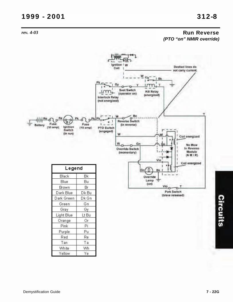
1999 - 2001 312-8
Run Reverse(PTO “on” NMIR override)
rev. 4-03
Legend
Black e, Blue ec
Er awn " Dark Blue Dk Bu
Dark Gr ee n Dk Gn
Gree n Co C" C
Li hi Blue Lt Bu Oran e C,
Pink ~ ,
Pur Ie Cc C., C. ''" " Wh ite W>
Ye ll ow ,.
~ iII_ I W ~-::-:::::~i:. con ' ______ •
, - --
I~"<.
,.'"~~ _.
I~M 'RI
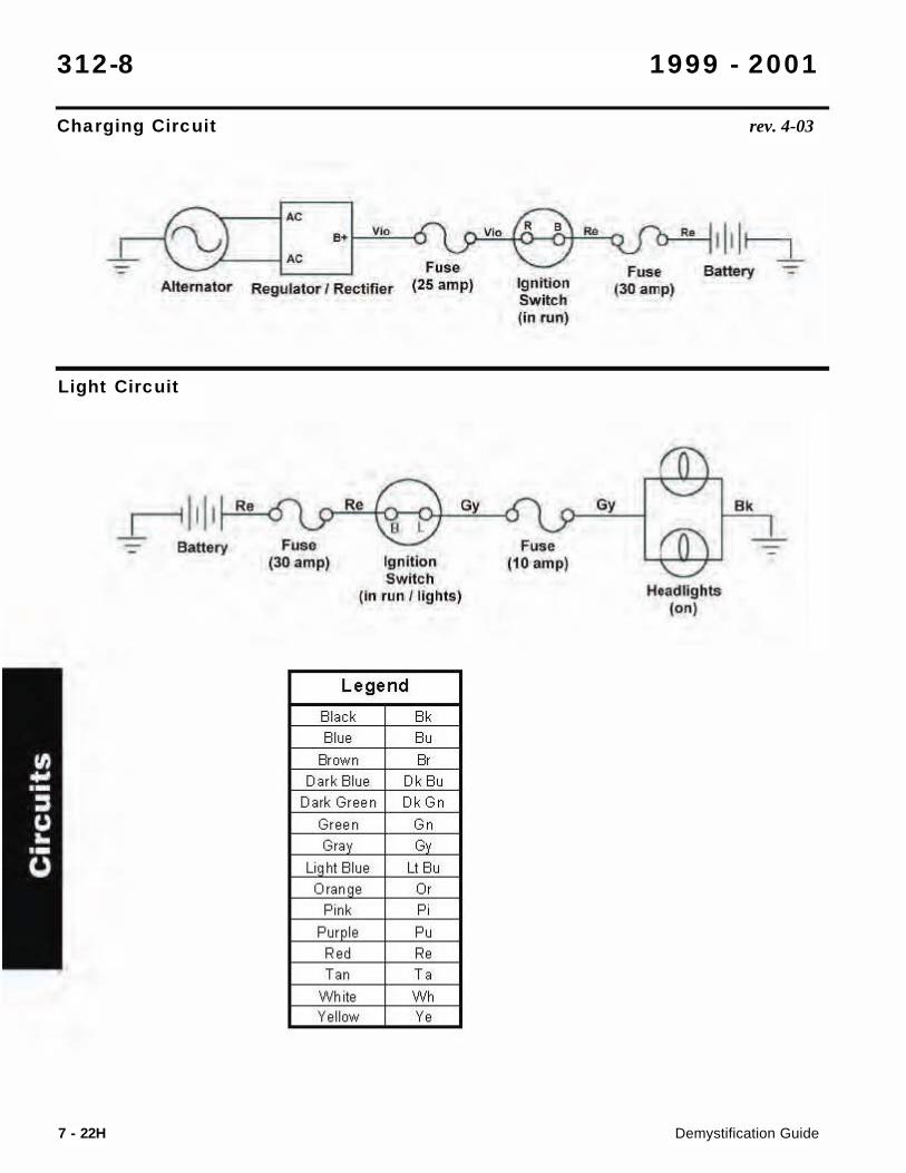
Charging Circuit
312-8 1999 - 2001
Demystification Guide7 - 22H
rev. 4-03
Light Circuit
~) I: ··1 •• 0\y ~8 ..L
- Fuse Altern.lor Regulator I RIIK:tifl.r (25 amp) Ignition
Switch Un run)
J..~"""ld'~ " " , Battery Fuse
(3G amp) Ignition Switch
(In run ' lights)
Legend
Blac k e, Blue ec
Erow n • Dark Blue Dk Btl
Da rk Gr ee n Dk Gn
Gr een Co C" C
Li hi Blue Lt Btl
Oran e C, Pink C,
Pur Ie C" c,' C,
'" " Wh ite "" Ye ll ow "
Fuse (10 amp)
~ cifb •. !JI II~ Fun Battery
(30 amp)
Hu tllights (on)
e.
-