Embed Size (px)
Citation preview

© 2003 Schneider Electric All Rights Reserved
WiringIntroduction
15
4WIRINGIntroduction
This chapter explains how to make the wiring connections for the power meter.
Required Protection for CE Compliance
For CE compliance, use a CE-compliant protection device such as a Merlin Gerin Disconnect Circuit Breaker Type P25M #21104 (or IEC 947 equivalent), which must be connected directly to the metering voltage and control power inputs.
NOTE: The disconnect circuit breaker must be placed within reach of the power meter and labeled: Disconnect Circuit Breaker for Power Meter.
Supported System Types
Table 4–1: Voltages Less Than or Equal to 347Vac L-N, Direct Connect No PTs
Single-Phase Wiring
Number of Wires
CTs Voltage Connections Meter Configuration
Qty. ID Qty. ID Type System Type PT Priority Scale
2 1 I1 2 V1, Vn L-N 10 No PT
2 1 I1 2 V1, V2 L-L 11 No PT
3 2 I1, I3 3 V1, V2,Vn L-L with N 12 No PT
Three-Phase Wiring
32 I1, I2 3 V1, V2, V3 Delta 30 No PT
3 I1, I2, I3 3 V1, V2, V3 Delta 31 No PT
4 3 I1, I2, I3 3 V1, V2, V3, Vn High Leg Delta
40 No PT
4 3 I1, I2, I3 3 V1, V2, V3, Vn Wye 40 No PT
© 2003 Schneider Electric All Rights Reserved
WiringWiring Diagrams
16
4
Wiring Diagrams
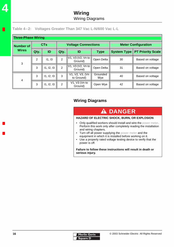
Table 4–2: Voltages Greater Than 347 Vac L-N/600 Vac L-L
Three-Phase Wiring
Number of Wires
CTs Voltage Connections Meter Configuration
Qty. ID Qty. ID Type System Type PT Priority Scale
3
2 I1, I3 2 V1, V3 (V2, Vn to Ground)
Open Delta 30 Based on voltage
3 I1, I2, I3 2 V1, V3 (V2, Vn to Ground) Open Delta 31 Based on voltage
43 I1, I2, I3 3
V1, V2, V3, (Vn to Ground)
Grounded Wye 40 Based on voltage
3 I1, I2, I3 2 V1, V3 (Vn to Ground)
Open Wye 42 Based on voltage
DANGERHAZARD OF ELECTRIC SHOCK, BURN, OR EXPLOSION
• Only qualified workers should install and wire the power meter. Perform this work only after completely reading the installation and wiring chapters.
• Turn off all power supplying the power meter and the equipment in which it is installed before working on it.
• Use a properly rated voltage testing device to verify that the power is off.
Failure to follow these instructions will result in death or serious injury.

© 2003 Schneider Electric All Rights Reserved
WiringWiring Diagrams
17
4
3-Phase 4-Wire Wye Direct Voltage Input Connection 3 CT
3-Phase 4-Wire Wye 3CT 2PT (calculated neutral)
NOTES:
• Use with 480Y/277 V and 208Y/120 V systems.• Use system type 3Ø4W3CT.
NOTE: Use system type 3Ø4W3CT2PT.
3-Phase 4-Wire Wye Connection 3 CT 3 PT Balanced 3-Phase 4-Wire Wye 3-Wire 3 PT 2 CT
NOTE: Use system type 3Ø4W3CT. NOTE: Use system type 3Ø4W2CT.
L1 L2 L3N
PM800
89
1011
12
1314
1516
17
1 2 3
VL-L=<600V
S2
S1
S2
S1
S2
S1
See control power options on page 20 L1 L2 L3N
PM800
89
1011
12
1314
1516
17
1 2 3
S2
S1
S2
S1
S2
S1
See control power options on page 20
L1 L2 L3N
89
1011
12
1314
1516
17
1 2 3
PM800
S2
S1
S2
S1
S2
S1
See control power options on page 20 L1 L2 L3N
PM800
89
1011
12
1314
1516
17
1 2 3
S2
S1
S2
S1
See control power options on page 20

© 2003 Schneider Electric All Rights Reserved
WiringWiring Diagrams
18
4
3-Phase 3-Wire Delta Connection 3CT 2PT 3-Phase 3-Wire 2 CT no PT (Direct Voltage Connection) Voltage Phase-Phase ≤ 600 V Nominal
NOTES:
• Use System type 3Ø3W3CT.• Install the jumper between V2 and VN when using
VTs on a 3-wire system. Do not use a jumper for a direct voltage connection (no VTs).
• For an open delta PT connection with 120 V L-L secondaries, use system type 3Ø3W2CT.
NOTES:
• Control power can be drawn from fused voltage inputs Phase-Phase or an external source.
• For corner grounded delta applications, use PTs.• Use system type 3Ø3W2CT.
3-Phase 3-Wire Delta Connection 2 CT 2 PT 1-Phase Line-to-Line 2-Wire System 1 CT
NOTES:
• Install the jumper between V2 and VN when using VTs on a 3-wire system. Do not use a jumper for a direct voltage connection (no VTs).
• For an open delta PT connection with 120 V L-L secondaries, use system type 3Ø3W2CT.
NOTE: The voltage input protection must be rated for the short circuit current at the connection points.
L1 L2 L3
PM800
89
1011
12
1314
1516
17
1 2 3
S2
S1
S2
S1
S2
S1
See control power options on page 20
L1 L2 L3
PM800
89
1011
12
1314
1516
17
1 2 3
S2
S1
S2
S1
Only when U<457 VAC
L1 L2 L3
PM800
89
1011
12
1314
1516
17
1 2 3
S2
S1
S2
S1
See control power options on page 20
PM800
L1 L2
89
1011
12
1314
1516
17
1 2 3
VL-L=< 600V
S2
S1
Only when U<457 VAC

© 2003 Schneider Electric All Rights Reserved
WiringWiring Diagrams
19
4
1-Phase Line-to-Neutral 2-Wire System 1 CT 1-Phase 3-Wire Direct Voltage Connection 2 CT
NOTE: This is supported in a future firmware release. Contact your local representative for a firmware update.
N L1
PM800
89
1011
12
1314
1516
17
1 2 3
VL-L=< 600V
S2
S1
Only when U<457 VAC L1 L2N
PM800
89
1011
12
1314
1516
17
1 2 3
VL-L=< 600V
S2
S1
S2
S1
Only when U<457 VAC
© 2003 Schneider Electric All Rights Reserved
WiringWiring Diagrams
20
4
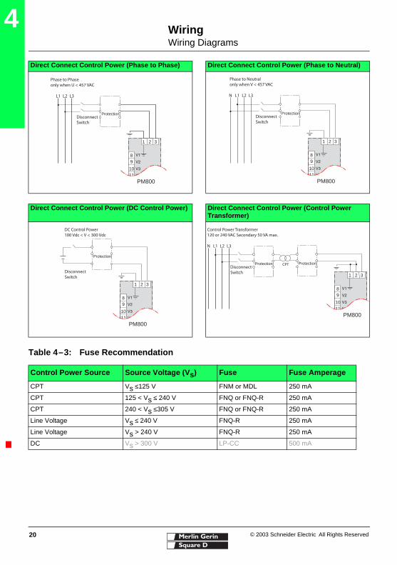
Direct Connect Control Power (Phase to Phase) Direct Connect Control Power (Phase to Neutral)
Direct Connect Control Power (DC Control Power) Direct Connect Control Power (Control Power Transformer)
L1 L2 L3
Disconnect Switch
Phase to Phaseonly when U < 457 VAC
Protection
89
1011
1 2 3
PM800
L1 L2 L3N
Disconnect Switch
Phase to Neutralonly when V < 457 VAC
Protection
89
1011
1 2 3
PM800
Disconnect Switch
DC Control Power100 Vdc < V < 300 Vdc
Protection
89
1011
1 2 3
PM800
L1 L2 L3N
Disconnect Switch
Control Power Transformer120 or 240 VAC Secondary 50 VA max.
CPTProtection Protection
89
1011
1 2 3
PM800
Table 4–3: Fuse Recommendation
Control Power Source Source Voltage (Vs) Fuse Fuse Amperage
CPT Vs ≤125 V FNM or MDL 250 mA
CPT 125 < Vs ≤ 240 V FNQ or FNQ-R 250 mA
CPT 240 < Vs ≤305 V FNQ or FNQ-R 250 mA
Line Voltage Vs ≤ 240 V FNQ-R 250 mA
Line Voltage Vs > 240 V FNQ-R 250 mA
DC Vs > 300 V LP-CC 500 mA

© 2003 Schneider Electric All Rights Reserved
CommunicationsCommunications Capabilities
21
5COMMUNICATIONSCommunications Capabilities
Table 5–1: Communications Capabilities of the Power Meter
Communications Port RS-485:
• 2-wire with shield• EIA compliant• Allows the power meter to be
connected to a daisy-chain of up to 32 devices
Baud Rate 9600
19200
38400
Communications Distances See Table 5–2 on page 21
Protocols MODBUS RTU
JBUS
Parity ODD
EVEN
NONE
Table 5–2: RS-485 Communications Distances
Baud Rate
Maximum Communication Distances
1 to 16 Devices 17 to 32 Devices
Feet Meters Feet Meters
9600 10,000 3,050 4,000 1,220
19200 5,000 1548 2,500 762.5
38400 2,500 762.5 1,500 457
NOTES:
• Distances are for 2-wire devices and 4-wire devices configured for 2-wire operation, such as the Series 600 Power Meter and the Series 3000 and 4000 Circuit Monitor.
• Distances listed should be used as a guide only and cannot be guaranteed for non-POWERLOGIC devices.
© 2003 Schneider Electric All Rights Reserved
CommunicationsConnecting to a PC Host Using the RS-485 Port
22
5
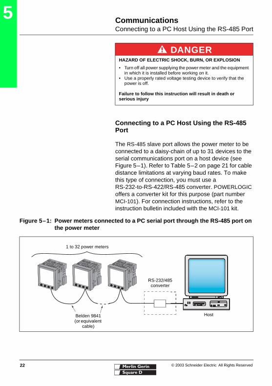
Connecting to a PC Host Using the RS-485 Port
The RS-485 slave port allows the power meter to be connected to a daisy-chain of up to 31 devices to the serial communications port on a host device (see Figure 5–1). Refer to Table 5–2 on page 21 for cable distance limitations at varying baud rates. To make this type of connection, you must use a RS-232-to-RS-422/RS-485 converter. POWERLOGIC offers a converter kit for this purpose (part number MCI-101). For connection instructions, refer to the instruction bulletin included with the MCI-101 kit.
DANGERHAZARD OF ELECTRIC SHOCK, BURN, OR EXPLOSION
• Turn off all power supplying the power meter and the equipment in which it is installed before working on it.
• Use a properly rated voltage testing device to verify that the power is off.
Failure to follow this instruction will result in death or serious injury
Figure 5–1: Power meters connected to a PC serial port through the RS-485 port on the power meter
Belden 9841 (or equivalent
cable)
1 to 32 power meters
Host
RS-232/485 converter

© 2003 Schneider Electric All Rights Reserved
CommunicationsDaisy-chaining Devices to the Power Meter
23
5
Daisy-chaining Devices to the Power Meter
The RS-485 slave port allows the power meter to be connected in a daisy chain with up to 31, 2-wire devices. In this bulletin, communications link refers to a chain of devices that are connected by a communications cable.
To daisy-chain devices to the power meter, use communications cable containing a twisted-shielded pair (Belden 9841 or equivalent) and the three-terminal connector of the RS-485 port on the power meter. The terminals are labeled:
18 (shield)
19 –
20 +
To connect to the power meter, follow these steps:
1. Strip the cable wires and insert them into the holes in the connector.
2. On the top of the connector, torque the wire binding screws 5–7 in-lb (0.56–0.79 N•m).
Daisy-chain 2-wire Devices
To daisy-chain the power meter to another 2-wire POWERLOGIC device, wire the power meter’s RS-485 communications terminals to the matching communications terminals of the next device. In other words, wire the + terminal of the power meter to the + terminal of the next device, wire – to –, and shield to shield as shown in Figure 5–3.
Figure 5–2: RS-485 connection
–+
18
19
20
Silver
White with bluestripe
Blue with whitestripe

© 2003 Schneider Electric All Rights Reserved
CommunicationsDaisy-chaining Devices to the Power Meter
24
5
• If the power meter is the first device on the daisy chain, connect it to the host device using the MCI-101 kit (or equivalent RS-232 to RS-422/RS-485 converter). See “Connecting the First Device on the Daisy Chain” on page 26 in this chapter for instructions.
• If the power meter is the last device on the daisy chain, terminate it. See “Terminating the Communications Link” on page 27 in this chapter for instructions.
• See Table 5–2 on page 21 for the maximum daisy-chain communications distances for 2-wire devices.
Using the MCT2W-485 Terminator
To terminate the power meter using the MCT2WMCTAS-485 terminator (part no. 3090MCTAS485), insert the wires of the terminator directly into terminals 19 and 20 of the RS-485 communications connector on the power meter as shown in Figure 5–3.
Figure 5–3: Daisy-chaining 2-wire devices
–+
Series 3000/4000 Circuit Monitor or other POWERLOGIC-compatible devices
Belden 9841 or equivalent
Belden 9841 wire colors: blue with white stripe (+), white with blue stripe (–), and silver (shield)
MCT2W-485 terminator on the last device of the
daisy chain