Embed Size (px)
Citation preview
WISCONSINBICYCLE FACILITY
DESIGN HANDBOOK
JANUARY 2004
WISCONSIN DEPARTMENT OF TRANSPORTATION
Minor updates in 2006 and 2009
AcknowledgementsThis guide is a product of the Wisconsin Department of Transportation, Division of Trans-portation Investment Management’s Bureau of Planning. John Williams of Tracy-WilliamsConsulting prepared the guide under contract with WisDOT, with assistance from TomWalsh, David Harkey, Glenn Grigg, and Todd Litman. Tom Huber of WisDOT managed theguide’s development. Significant contributions and review of the document were provided bythe WisDOT Bicycle Committee including Mike Rewey, David Genson, Tom Dobson, PatFleming, Bob Pfeiffer, and Doug Dalton. Special thanks to David Liebel of the UW-MadisonDepartment of Engineering Professional Development for preparing the section on bicyclepath lighting. Beneficial comments and many photos were provided by Arthur Ross and TomWalsh of the City of Madison. Thanks also to Rob Miller of the WisDOT Office of PublicAffairs for his review.
Numerous state bicycle facility design manuals and guidelines were reviewed in the prepara-tion of this handbook and their language formed the basis of some of this guide’s recommen-dations. Their efforts are much appreciated and this guide is intended to contribute, wherepossible, to future work of these and other agencies as well. Going back to the 1970s, statebicycle facility guides have built upon each other and it is common to see language andgraphics from one used in another. This process of incremental improvement is crucial to thedevelopment of the field. Primary sources for this handbook include bicycle guides from thestates of Arizona, California, Florida, Minnesota, North Carolina, Oregon, and Washington. Inseveral cases, figures and tables were based on — or used directly from these guides. Insuch cases, these sources were properly credited below the figure or table. Four figureswere either based on the Oregon Bicycle and Pedestrian Plan or redrawn from the plan. Onefigure was based on the Florida DOT Trail Intersection Design Handbook.
Other significant sources for the development of this guide were the Guide for the Develop-ment of Bicycle Facilities published by American Association of State Highway and Trans-portation Officials (AASHTO) and the Manual of Uniform Traffic Control Devices (MUTCD)from the Federal Highway Administration. Data from six tables and four figures were useddirectly from the AASHTO Guide to maintain consistency with this national guide. The major-ity of these tables and graphics covered technical data related to stopping sight distances,crests of vertical curves, and lateral clearances for horizontal curves for shared-use paths.Sources were properly credited below the figures or tables. Similarly, about a dozen graphicswere used from the MUTCD. Because the MUTCD has legal standing, the graphics are iden-tical or nearly identical to those appearing in the MUTCD.
In some cases, the same wording for sentences that appear in the AASHTO Guide appear inthis guide. This was done in cases where just a small word change in the statement mayalter the meaning and, thus, consistency between the two guides. WisDOT is a member ofAASHTO and has contributed significantly in the udpates of the AASHTO Guide.
Photo credits belong to Mike Rewey: figs. 2-32, 2-53, 2-55; Arthur Ross: figs. 2-5, 2-28, 2-43, 2-46, 2-52, 4-158, 4-159; Pat Fleming: figs. 2-11, 3-13; Tom Walsh: figs. 2-24, 2-44; KurtMiller: fig. 2-27; Donna Brown: fig. 4-1; Dan Burden figs. 1-6, 2-37, 2-60, 2-78, 3-2, 3-3, 3-6,3-10, 3-17, 3-20, 3-31, 3-33, 3-34, 3-37, 4-2, 4-9, 4-21, 4-29, 4-37, 4-44, 4-62, 4-71, 4-80, 4-85, 4-87, 4-93, 4-97, 4-99, 4-102, 4-103, 4-109, 4-112, 4-114, 4-115, 4-122, 4-138, 4-139, 4-143, 4-145, 4-151, 4-155; Ellen Fletcher: fig. 2-66; David Takemoto-Weerts: fig. 3-42; AlexSorton: figs. 3-5, 3-7, 4-67, 4-89, 4-157; Peter Lagerwey: figs. 2-38, 2-42, 2-58, 2-64, 2-75;Bikeinfo.org: fig. 1-7; Gary MacFadden: fig. 2-22; City of Portland, Oregon: 4-84; WisDOT:fig. 2-81; City of Lincoln, Nebraska: fig. 4-90; Kane County Forest Preserve District: fig. 4-130. All other photos by John Williams and Tom Huber.
For information about this document, contact: Tom Huber, WisDOT Urban Planning Section,at (608) 267-7757 or (608) 266-3661; by mail at Wisconsin Department of Transportation,Box 7913, Madison, WI. 53707-7913; or by e-mail at <[email protected]>.
i Wisconsin Bicycle Facility Design Handbook
WISCONSIN
BICYCLE
FACILITY
DESIGN
HANDBOOK
WISC0NSIN DEPARTMENT OF
TRANSPORTATION
2004
Wisconsin Bicycle Facility Design Handbook ii
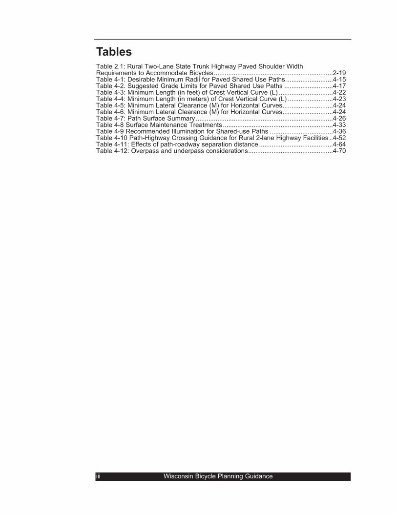
TablesTable 2.1: Rural Two-Lane State Trunk Highway Paved Shoulder WidthRequirements to Accommodate Bicycles..................................................................2-19Table 4-1: Desirable Minimum Radii for Paved Shared Use Paths ..........................4-15Table 4-2. Suggested Grade Limits for Paved Shared Use Paths ...........................4-17Table 4-3: Minimum Length (in feet) of Crest Vertical Curve (L) ..............................4-22Table 4-4: Minimum Length (in meters) of Crest Vertical Curve (L) .........................4-23Table 4-5: Minimum Lateral Clearance (M) for Horizontal Curves............................4-24Table 4-6: Minimum Lateral Clearance (M) for Horizontal Curves............................4-24Table 4-7: Path Surface Summary ............................................................................4-26Table 4-8 Surface Maintenance Treatments .............................................................4-33Table 4-9 Recommended Illumination for Shared-use Paths ...................................4-36Table 4-10 Path-Highway Crossing Guidance for Rural 2-lane Highway Facilities ..4-52Table 4-11: Effects of path-roadway separation distance .........................................4-64Table 4-12: Overpass and underpass considerations...............................................4-70
iii Wisconsin Bicycle Planning Guidance
1 Introduction .......................................................1-11.1 Bicycle and bicyclist characteristics ..........................1-2
1.2 Design options...........................................................1-5
2 Basic Roadway Improvements .............2-12.1 Roadway types..........................................................2-1
2.1.1 Residential streets ...............................................2-12.1.2 Collector streets ...................................................2-22.1.3 Arterial streets......................................................2-42.1.4 Rural highways ....................................................2-5
2.2 Pavement quality.......................................................2-72.3 Drainage grates and utility covers.............................2-9
2.3.1 Grate type ............................................................2-92.3.2 Grate or utility cover location .............................2-102.3.3 Grate or utility cover elevation ...........................2-112.3.4 Temporary measures.........................................2-11
2.4 Corner sight lines ....................................................2-122.5 Wide outside lanes..................................................2-13
2.5.1 Retrofitting an existing roadway.........................2-152.6 Paved shoulders......................................................2-17
2.6.1 Low-volume rural roads .....................................2-172.6.2 Overall shoulder width .......................................2-182.6.3 Basic recommendations.....................................2-182.6.4 Guardrails and slopes........................................2-202.6.5 Grades ...............................................................2-202.6.6 Pavement design and loading ...........................2-212.6.7 Joints between travel lanes and shoulders........2-212.6.8 Unpaved driveways............................................2-212.6.9 Rumble strips .....................................................2-22
2.7 Railroad crossings...................................................2-232.7.1 Crossing angles and gaps .................................2-232.7.2 Crossing smoothness ........................................2-262.7.3 Railroad/path or walkway crossings ..................2-26
2.8 Traffic signals ..........................................................2-272.8.1 Bicycle detection ................................................2-272.8.2 Signal loop markings .........................................2-292.8.3 Signal timing ......................................................2-302.8.4 Programmed visibility heads..............................2-30
2.9 Structures ................................................................2-312.9.1 Bridges...............................................................2-322.9.2 Interchanges ......................................................2-36
2.10 Traffic Calming ......................................................2-392.10.1 Traffic diversion approaches............................2-402.10.2 Measures for slowing traffic .............................2-42
2.11 Bicycle Route Designation ....................................2-45
3 Bicycle Lanes...................................................3-13.1 One-way vs. two-way bicycle lanes ..........................3-23.2 Bicycle lane location..................................................3-33.3 Bicycle lane surface quality.......................................3-83.4 Bicycle lane width......................................................3-93.5 Bicycle lane designation..........................................3-143.6 Bicycle lane intersection design ..............................3-183.7 Intersections with right-turn lanes ...........................3-213.8 Left-turn bicycle lane ...............................................3-233.9 Interchanges............................................................3-24
4 Shared-use Paths ..........................................4-14.1 Shared-use path users, purposes, and locations......4-14.2 Designing paths and roads .......................................4-24.3 Shared-use paths and roadways ..............................4-3
4.3.1 Problems with paths next to roadways ..................4-34.3.2 Sidewalk bikeways .................................................4-64.3.3 Shared-use paths in roadway medians..................4-74.4. Path width.................................................................4-74.5 Shoulders and clearances.........................................4-94.6 Design Speed..........................................................4-114.7 Horizontal alignment & superelevation....................4-134.8 Grades.....................................................................4-174.9 Transitions between grades and level ground ........4-184-10 Sight Distance .......................................................4-194.11 Pavement structure ...............................................4-25
4.11.1 Pavement loads ...............................................4-274.11.2 Vegetation Control ...........................................4-284.11.3 Foundation preparation....................................4-294.11.4 Asphalt structural section.................................4-304.11.5 Concrete structural section ..............................4-314.11.6 Aggregate Structural section ...........................4-314.11.7 Surface smoothness and maintenance ...........4-33
4.12 Drainage................................................................4-344.13 Lighting..................................................................4-354.14 Signing and marking .............................................4-38
4.14.1 Regulatory controls ..........................................4-384.14.2 Warning devices ..............................................4-414.14.3 Informational devices .......................................4-424.14.4 Temporary work zone controls ........................4-444.14.5 Placement of signs ..........................................4-454.14.6 Sizes of signs...................................................4-464.14.7 Using restraint..................................................4-46
4.15 Path-Roadway Crossings......................................4-474.15.1 Choosing crossing locations ............................4-474.15.2 Intersection: yes or no? ...................................4-484.15.3 Rural vs. urban/suburban locations .................4-50
4.15.3.1 Rural path crossings...................................4-504.15.3.2 Urban/suburban path crossings .................4-53
4.15.4 Crossing design ...............................................4-554.15.4.1 Simple signed crossing ..............................4-564.15.4.2 Signed crossings with traffic calming .........4-594.15.4.3 Signalized crossings...................................4-61
4.15.5 Parallel Path Crossings ...................................4-634.15.5.1 Signalized parallel crossings ......................4-654.15.5.2 Signed parallel crossings ...........................4-66
4.15.6 Important features of all crossings...................4-674.15.7 Grade separations ...........................................4-69
4.16 Shared-use path structures...................................4-714.16.1 Bridges and overpasses ..................................4-724.16.2 Underpasses and tunnels ................................4-754.16.3 Combining structures .......................................4-794.16.4 Separation on Combined Structures................4-81
4.17 Shared Use ...........................................................4-834.17.1 Pedestrians and Bicyclists ...............................4-834.17.2 Motorbikes and motorcycles ............................4-864.17.3 Motor vehicles..................................................4-874.17.4 Horses..............................................................4-914.17.5 Cross-country skiers and snowmobiles ...........4-92
AppendicesA Maintenance & Operations..........................................A-1B Traffic Conditions & Bridges........................................B-1C Wisconsin Statutes......................................................C-1D Bibliography ................................................................D-1E Index............................................................................E-1
Wisconsin Bicycle Facility Design Manual iv
Wisconsin Bicycle Facility Design Manual
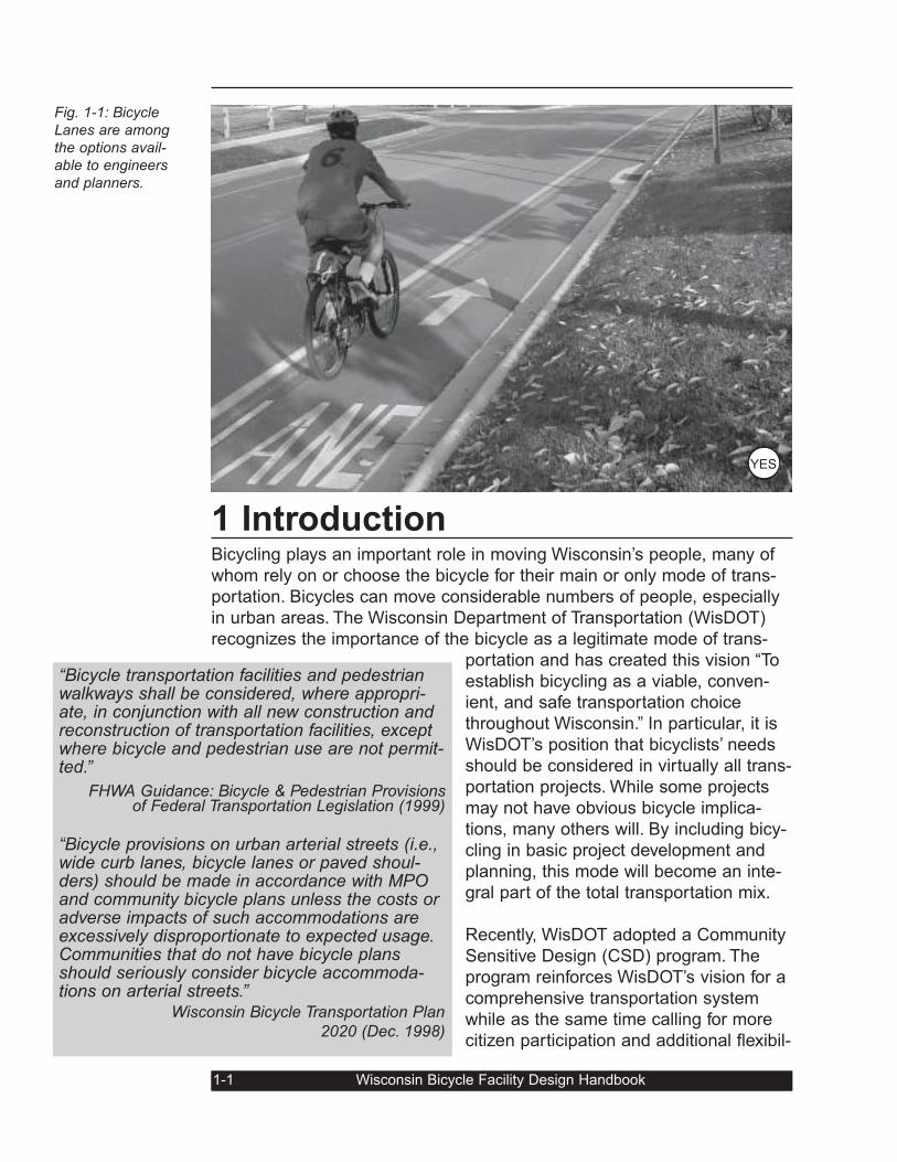
1 IntroductionBicycling plays an important role in moving Wisconsin’s people, many of
whom rely on or choose the bicycle for their main or only mode of trans-
portation. Bicycles can move considerable numbers of people, especially
in urban areas. The Wisconsin Department of Transportation (WisDOT)
recognizes the importance of the bicycle as a legitimate mode of trans-
portation and has created this vision “To
establish bicycling as a viable, conven-
ient, and safe transportation choice
throughout Wisconsin.” In particular, it is
WisDOT’s position that bicyclists’ needs
should be considered in virtually all trans-
portation projects. While some projects
may not have obvious bicycle implica-
tions, many others will. By including bicy-
cling in basic project development and
planning, this mode will become an inte-
gral part of the total transportation mix.
Recently, WisDOT adopted a Community
Sensitive Design (CSD) program. The
program reinforces WisDOT’s vision for a
comprehensive transportation system
while as the same time calling for more
citizen participation and additional flexibil-
1-1 Wisconsin Bicycle Facility Design Handbook
Fig. 1-1: BicycleLanes are amongthe options avail-able to engineersand planners.
“Bicycle transportation facilities and pedestrianwalkways shall be considered, where appropri-ate, in conjunction with all new construction andreconstruction of transportation facilities, exceptwhere bicycle and pedestrian use are not permit-ted.”
FHWA Guidance: Bicycle & Pedestrian Provisions of Federal Transportation Legislation (1999)
“Bicycle provisions on urban arterial streets (i.e.,wide curb lanes, bicycle lanes or paved shoul-ders) should be made in accordance with MPOand community bicycle plans unless the costs oradverse impacts of such accommodations areexcessively disproportionate to expected usage.Communities that do not have bicycle plansshould seriously consider bicycle accommoda-tions on arterial streets.”
Wisconsin Bicycle Transportation Plan2020 (Dec. 1998)
YES
ity in roadway design standards. As a starting point for projects designed
under CSD, bicycle and pedestrian accommodations should be assumed
to be part of those projects. This guide will act as a detailed resource in
how to accomplish that.
Designers have a wide range of possible options for enhancing a commu-
nity’s bicycle transportation system. On the one hand, improvements can
be simple, inexpensive, and involve minimal design effort. For example,
adopting a “bicycle-safe” drainage grate standard, patching pot holes on
popular bicycling routes, or adjusting traffic signal timing can be an inex-
pensive ways to make bicycling safer and more enjoyable.
On the other hand, some improvements can involve substantial alloca-
tions of funds, carefully prepared detailed designs, and multi-year commit-
ments to phased development. An example might be the implementation
of an extensive community-wide trail network or building a key bicycle
bridge to get bicyclists past a major bicycling barrier.
In order to adequately design for bicyclists, particularly when approaching
large-scale projects, one must have a basic understanding of how bicy-
cles operate. Most designers have an intuitive understanding of such
aspects for motor vehicle operation from years of driving. But that under-
standing is less common when designers deal with bicycles. As a result, it
is important to begin with basic concepts and characteristics.
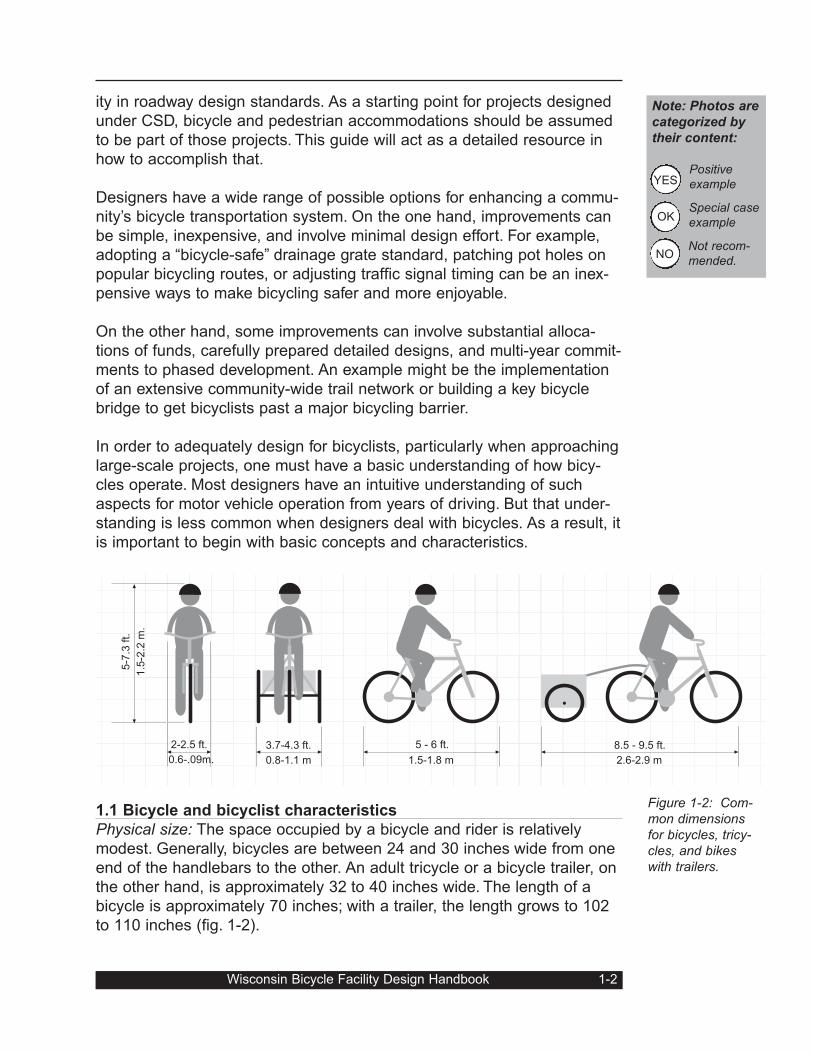
1.1 Bicycle and bicyclist characteristics
Physical size: The space occupied by a bicycle and rider is relatively
modest. Generally, bicycles are between 24 and 30 inches wide from one
end of the handlebars to the other. An adult tricycle or a bicycle trailer, on
the other hand, is approximately 32 to 40 inches wide. The length of a
bicycle is approximately 70 inches; with a trailer, the length grows to 102
to 110 inches (fig. 1-2).
Wisconsin Bicycle Facility Design Handbook 1-2
Figure 1-2: Com-mon dimensionsfor bicycles, tricy-cles, and bikeswith trailers.
2.6-2.9 m1.5-1.8 m0.8-1.1 m
2-2.5 ft.
1.5
-2.2
m.
0.6-.09m.
3.7-4.3 ft. 5 - 6 ft. 8.5 - 9.5 ft.
5-7
.3 ft.
Note: Photos are
categorized by
their content:
Positiveexample
Special caseexample
Not recom-mended.
YES
OK
NO
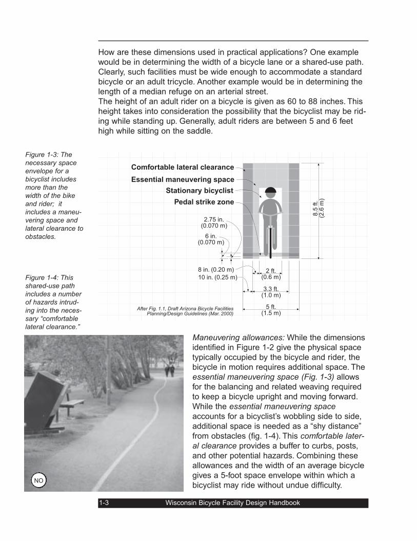
How are these dimensions used in practical applications? One example
would be in determining the width of a bicycle lane or a shared-use path.
Clearly, such facilities must be wide enough to accommodate a standard
bicycle or an adult tricycle. Another example would be in determining the
length of a median refuge on an arterial street.
The height of an adult rider on a bicycle is given as 60 to 88 inches. This
height takes into consideration the possibility that the bicyclist may be rid-
ing while standing up. Generally, adult riders are between 5 and 6 feet
high while sitting on the saddle.
Maneuvering allowances: While the dimensions
identified in Figure 1-2 give the physical space
typically occupied by the bicycle and rider, the
bicycle in motion requires additional space. The
essential maneuvering space (Fig. 1-3) allows
for the balancing and related weaving required
to keep a bicycle upright and moving forward.
While the essential maneuvering spaceaccounts for a bicyclist’s wobbling side to side,
additional space is needed as a “shy distance”
from obstacles (fig. 1-4). This comfortable later-al clearance provides a buffer to curbs, posts,
and other potential hazards. Combining these
allowances and the width of an average bicycle
gives a 5-foot space envelope within which a
bicyclist may ride without undue difficulty.
1-3 Wisconsin Bicycle Facility Design Handbook
Figure 1-3: Thenecessary spaceenvelope for abicyclist includesmore than thewidth of the bikeand rider; itincludes a maneu-vering space andlateral clearance toobstacles.
Figure 1-4: Thisshared-use pathincludes a numberof hazards intrud-ing into the neces-sary “comfortablelateral clearance.”
Stationary bicyclist
Essential maneuvering space
Comfortable lateral clearance
After Fig. 1.1, Draft Arizona Bicycle FacilitiesPlanning/Design Guidelines (Mar. 2000)
2 ft.(0.6 m)
Pedal strike zone
3.3 ft.(1.0 m)
5 ft.(1.5 m)
8 in. (0.20 m)
10 in. (0.25 m)
2.75 in.(0.070 m)
6 in.(0.070 m)
8.5
ft.
(2.6
m)
NO
An additional clearance factor should be
taken into account, however, and this
may be called the pedal strike zone. A
bicyclist riding close to a low curb may
strike a pedal on the top of that curb. As
the pedal travels down and backward in
its circular motion, the rear wheel may lift
off the ground causing a crash. Low
obstacles of this nature should be kept
away from the likely path of bicyclists.
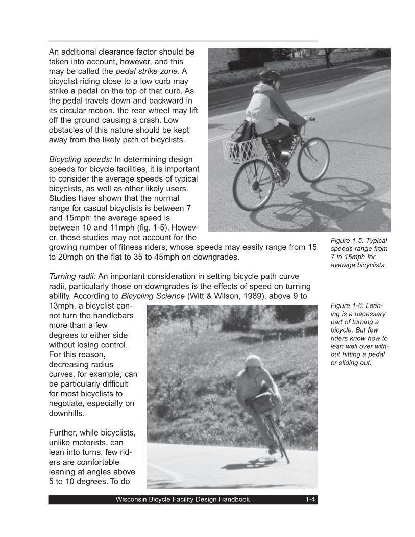
Bicycling speeds: In determining design
speeds for bicycle facilities, it is important
to consider the average speeds of typical
bicyclists, as well as other likely users.
Studies have shown that the normal
range for casual bicyclists is between 7
and 15mph; the average speed is
between 10 and 11mph (fig. 1-5). Howev-
er, these studies may not account for the
growing number of fitness riders, whose speeds may easily range from 15
to 20mph on the flat to 35 to 45mph on downgrades.
Turning radii: An important consideration in setting bicycle path curve
radii, particularly those on downgrades is the effects of speed on turning
ability. According to Bicycling Science (Witt & Wilson, 1989), above 9 to
13mph, a bicyclist can-
not turn the handlebars
more than a few
degrees to either side
without losing control.
For this reason,
decreasing radius
curves, for example, can
be particularly difficult
for most bicyclists to
negotiate, especially on
downhills.
Further, while bicyclists,
unlike motorists, can
lean into turns, few rid-
ers are comfortable
leaning at angles above
5 to 10 degrees. To do
Wisconsin Bicycle Facility Design Handbook 1-4
Figure 1-5: Typicalspeeds range from7 to 15mph foraverage bicyclists.
Figure 1-6: Lean-ing is a necessarypart of turning abicycle. But fewriders know how tolean well over with-out hitting a pedalor sliding out.
so puts the inexperienced rider at risk of either sliding out or hitting the
inside pedal on the pavement. As a result of these factors, bike path
curve radii, for example, should be designed in a conservative manner.
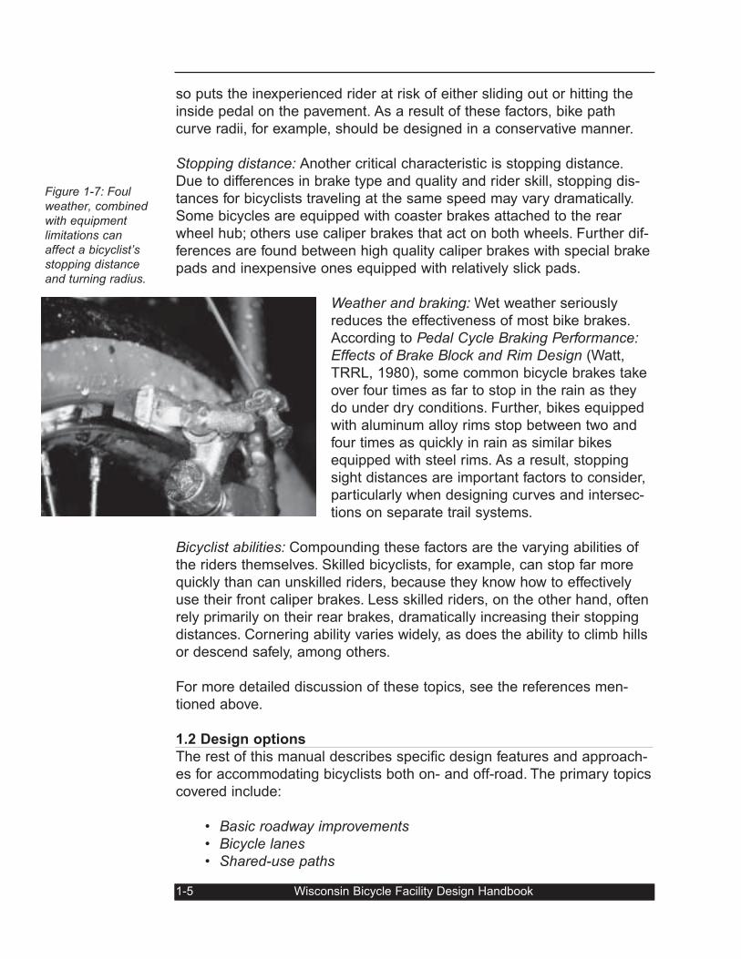
Stopping distance: Another critical characteristic is stopping distance.
Due to differences in brake type and quality and rider skill, stopping dis-
tances for bicyclists traveling at the same speed may vary dramatically.
Some bicycles are equipped with coaster brakes attached to the rear
wheel hub; others use caliper brakes that act on both wheels. Further dif-
ferences are found between high quality caliper brakes with special brake
pads and inexpensive ones equipped with relatively slick pads.
Weather and braking: Wet weather seriously
reduces the effectiveness of most bike brakes.
According to Pedal Cycle Braking Performance:Effects of Brake Block and Rim Design (Watt,
TRRL, 1980), some common bicycle brakes take
over four times as far to stop in the rain as they
do under dry conditions. Further, bikes equipped
with aluminum alloy rims stop between two and
four times as quickly in rain as similar bikes
equipped with steel rims. As a result, stopping
sight distances are important factors to consider,
particularly when designing curves and intersec-
tions on separate trail systems.
Bicyclist abilities: Compounding these factors are the varying abilities of
the riders themselves. Skilled bicyclists, for example, can stop far more
quickly than can unskilled riders, because they know how to effectively
use their front caliper brakes. Less skilled riders, on the other hand, often
rely primarily on their rear brakes, dramatically increasing their stopping
distances. Cornering ability varies widely, as does the ability to climb hills
or descend safely, among others.
For more detailed discussion of these topics, see the references men-
tioned above.
1.2 Design options
The rest of this manual describes specific design features and approach-
es for accommodating bicyclists both on- and off-road. The primary topics
covered include:
• Basic roadway improvements• Bicycle lanes• Shared-use paths
1-5 Wisconsin Bicycle Facility Design Handbook
Figure 1-7: Foulweather, combinedwith equipment limitations canaffect a bicyclist’sstopping distanceand turning radius.

Wisconsin Bicycle Facility Design Handbook 1-6
2. Basic Roadway ImprovementsThe street system provides the basic network for bicycle travel. Other ele-
ments (e.g., bike lanes and paths) supplement this system. To make most
streets work for bicyclists, basic improvements may be needed. Such
things as safe railroad crossings, traffic signals that work for bicyclists,
and street networks that connect benefit bicyclists and make more bicycle
trips possible and likely.
2.1 Roadway typesWhile the most basic improvements are appropriate for all categories of
street, some improvements are most appropriate for certain categories. In
a typical community, streets types range from quiet residential streets, to
minor collector streets, to major arterials, and highways or expressways.
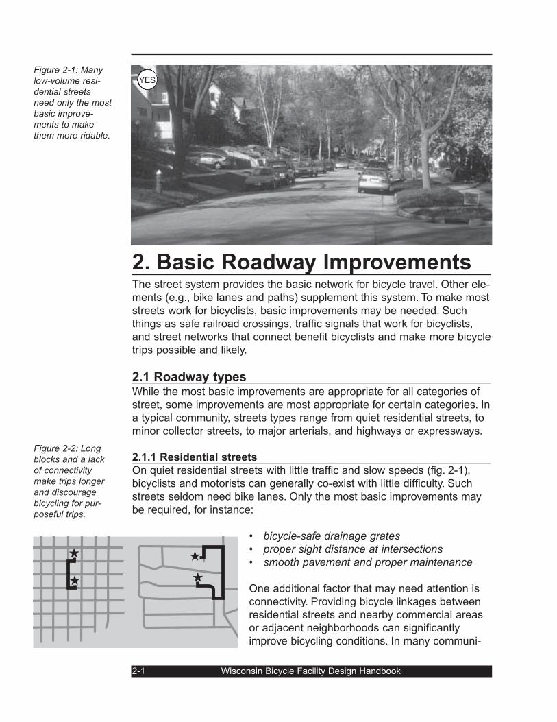
2.1.1 Residential streets
On quiet residential streets with little traffic and slow speeds (fig. 2-1),
bicyclists and motorists can generally co-exist with little difficulty. Such
streets seldom need bike lanes. Only the most basic improvements may
be required, for instance:
• bicycle-safe drainage grates• proper sight distance at intersections• smooth pavement and proper maintenance
One additional factor that may need attention is
connectivity. Providing bicycle linkages between
residential streets and nearby commercial areas
or adjacent neighborhoods can significantly
improve bicycling conditions. In many communi-
2-1 Wisconsin Bicycle Facility Design Handbook
Figure 2-1: Manylow-volume resi-dential streetsneed only the mostbasic improve-ments to makethem more ridable.
Figure 2-2: Longblocks and a lackof connectivitymake trips longerand discouragebicycling for pur-poseful trips.
YES
ties, newer parts of town tend to have dis-
continuous street networks that require bicy-
clists, pedestrians, and motorists to travel a
long distance to get to a nearby destination
(fig. 2-2) and also force bicyclists onto busier
streets than necessary.
Since most bicycle and pedestrian trips are
short, such discontinuities can discourage
bicycling and walking. Improving connections where possible can help
solve this problem (fig. 2-3).
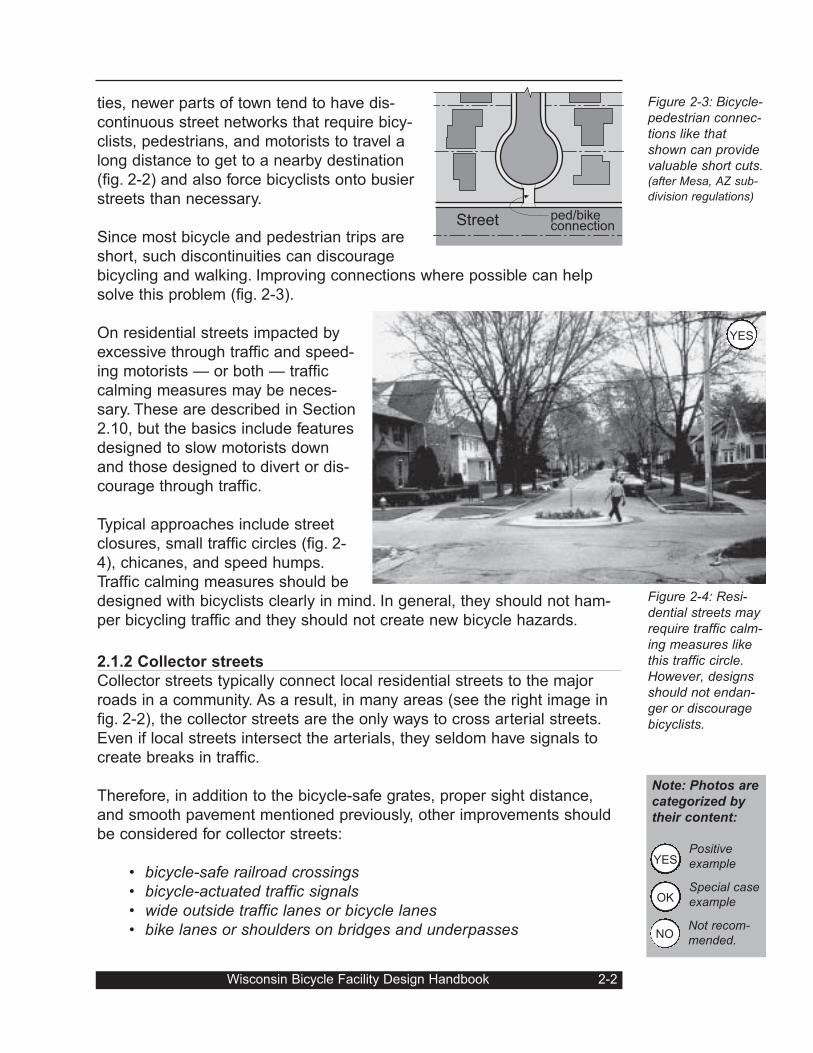
On residential streets impacted by
excessive through traffic and speed-
ing motorists — or both — traffic
calming measures may be neces-
sary. These are described in Section
2.10, but the basics include features
designed to slow motorists down
and those designed to divert or dis-
courage through traffic.
Typical approaches include street
closures, small traffic circles (fig. 2-
4), chicanes, and speed humps.
Traffic calming measures should be
designed with bicyclists clearly in mind. In general, they should not ham-
per bicycling traffic and they should not create new bicycle hazards.
2.1.2 Collector streets
Collector streets typically connect local residential streets to the major
roads in a community. As a result, in many areas (see the right image in
fig. 2-2), the collector streets are the only ways to cross arterial streets.
Even if local streets intersect the arterials, they seldom have signals to
create breaks in traffic.
Therefore, in addition to the bicycle-safe grates, proper sight distance,
and smooth pavement mentioned previously, other improvements should
be considered for collector streets:
• bicycle-safe railroad crossings• bicycle-actuated traffic signals• wide outside traffic lanes or bicycle lanes• bike lanes or shoulders on bridges and underpasses
Wisconsin Bicycle Facility Design Handbook 2-2
Figure 2-3: Bicycle-pedestrian connec-tions like thatshown can providevaluable short cuts.(after Mesa, AZ sub-
division regulations)
Figure 2-4: Resi-dential streets mayrequire traffic calm-ing measures likethis traffic circle.However, designsshould not endan-ger or discouragebicyclists.
Street ped/bikeconnection
Note: Photos are
categorized by
their content:
Positiveexample
Special caseexample
Not recom-mended.
OK
NO
YES
YES
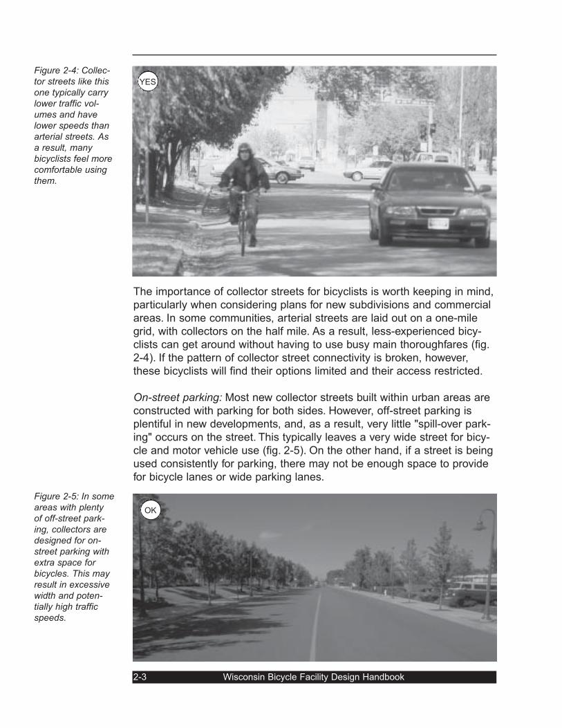
The importance of collector streets for bicyclists is worth keeping in mind,
particularly when considering plans for new subdivisions and commercial
areas. In some communities, arterial streets are laid out on a one-mile
grid, with collectors on the half mile. As a result, less-experienced bicy-
clists can get around without having to use busy main thoroughfares (fig.
2-4). If the pattern of collector street connectivity is broken, however,
these bicyclists will find their options limited and their access restricted.
On-street parking: Most new collector streets built within urban areas are
constructed with parking for both sides. However, off-street parking is
plentiful in new developments, and, as a result, very little "spill-over park-
ing" occurs on the street. This typically leaves a very wide street for bicy-
cle and motor vehicle use (fig. 2-5). On the other hand, if a street is being
used consistently for parking, there may not be enough space to provide
for bicycle lanes or wide parking lanes.
2-3 Wisconsin Bicycle Facility Design Handbook
Figure 2-4: Collec-tor streets like thisone typically carrylower traffic vol-umes and havelower speeds thanarterial streets. Asa result, manybicyclists feel morecomfortable usingthem.
Figure 2-5: In someareas with plentyof off-street park-ing, collectors aredesigned for on-street parking withextra space forbicycles. This mayresult in excessivewidth and poten-tially high trafficspeeds.
OK
YES
Planners should be aware of this situation when evaluating and planning
for collector streets. If additional width is built into collector streets to
accommodate bicyclists and parked cars, but the street is rarely being
parked on, the excessive width may result in high traffic speeds.
When transportation planners created bicycle plans for metro areas in the
mid-1990's, several reported a mismatch between what bicyclists were
telling them about collector street bicycling conditions and what would be
expected, based upon accepted standards. Their initial analysis told them
the streets were narrow and uncomfortable for bicycling. But the bicyclists
told them there was plenty of space. The reason for this difference in per-
spective was the lack of parked cars on the streets.
If only sporadic parking is expected, new collector streets should be con-
sidered for one-side parking. Similarly, restriping existing collector streets
to restrict parking to one side may improve conditions for bicyclists who
have to otherwise move left around the occasional parked car.
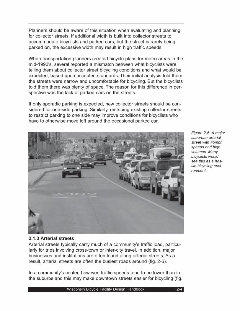
2.1.3 Arterial streets
Arterial streets typically carry much of a community’s traffic load, particu-
larly for trips involving cross-town or inter-city travel. In addition, major
businesses and institutions are often found along arterial streets. As a
result, arterial streets are often the busiest roads around (fig. 2-6).
In a community’s center, however, traffic speeds tend to be lower than in
the suburbs and this may make downtown streets easier for bicycling (fig.
Wisconsin Bicycle Facility Design Handbook 2-4
Figure 2-6: A majorsuburban arterialstreet with 45mphspeeds and highvolumes. Manybicyclists wouldsee this as a hos-tile bicycling envi-ronment.
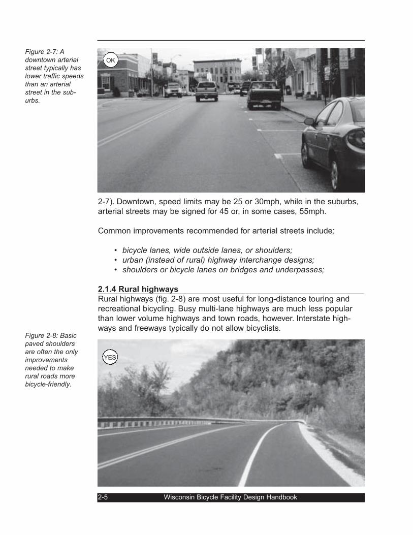
2-7). Downtown, speed limits may be 25 or 30mph, while in the suburbs,
arterial streets may be signed for 45 or, in some cases, 55mph.
Common improvements recommended for arterial streets include:
• bicycle lanes, wide outside lanes, or shoulders;• urban (instead of rural) highway interchange designs;• shoulders or bicycle lanes on bridges and underpasses;
2.1.4 Rural highways
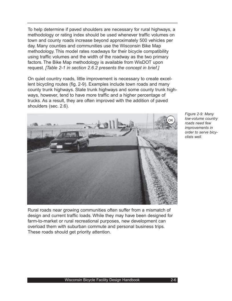
Rural highways (fig. 2-8) are most useful for long-distance touring and
recreational bicycling. Busy multi-lane highways are much less popular
than lower volume highways and town roads, however. Interstate high-
ways and freeways typically do not allow bicyclists.
2-5 Wisconsin Bicycle Facility Design Handbook
Figure 2-7: Adowntown arterialstreet typically haslower traffic speedsthan an arterialstreet in the sub-urbs.
Figure 2-8: Basicpaved shouldersare often the onlyimprovementsneeded to makerural roads morebicycle-friendly.
OK
YES
To help determine if paved shoulders are necessary for rural highways, a
methodology or rating index should be used whenever traffic volumes on
town and county roads increase beyond approximately 500 vehicles per
day. Many counties and communities use the Wisconsin Bike Map
methodology. This model rates roadways for their bicycle compatibility
using traffic volumes and the width of the roadway as the two primary
factors. The Bike Map methodology is available from WisDOT upon
request. [Table 2-1 in section 2.6.2 presents the concept in brief.]
On quiet country roads, little improvement is necessary to create excel-
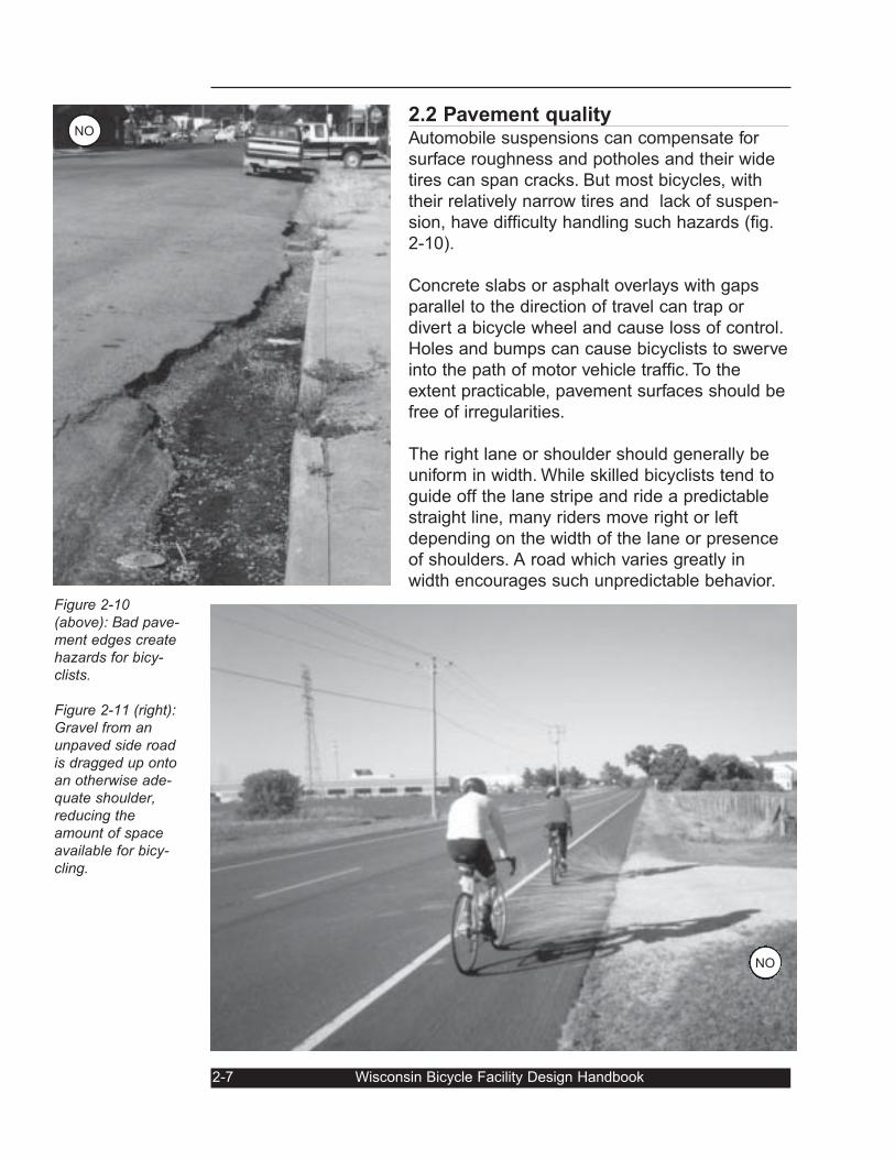
lent bicycling routes (fig. 2-9). Examples include town roads and many
county trunk highways. State trunk highways and some county trunk high-
ways, however, tend to have more traffic and a higher percentage of
trucks. As a result, they are often improved with the addition of paved
shoulders (sec. 2.6).
Rural roads near growing communities often suffer from a mismatch of
design and current traffic loads. While they may have been designed for
farm-to-market or rural recreational purposes, new development can
overload them with suburban commute and personal business trips.
These roads should get priority attention.
Wisconsin Bicycle Facility Design Handbook 2-6
Figure 2-9: Manylow-volume countryroads need fewimprovements inorder to serve bicy-clists well.
OK
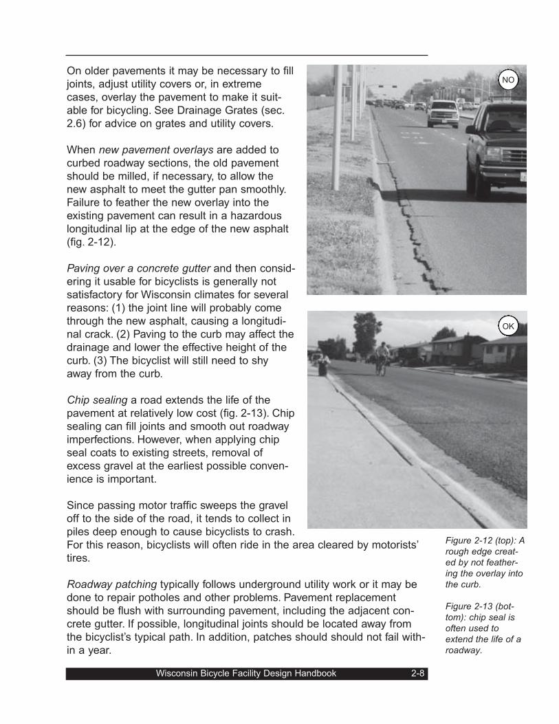
2.2 Pavement qualityAutomobile suspensions can compensate for
surface roughness and potholes and their wide
tires can span cracks. But most bicycles, with
their relatively narrow tires and lack of suspen-
sion, have difficulty handling such hazards (fig.
2-10).
Concrete slabs or asphalt overlays with gaps
parallel to the direction of travel can trap or
divert a bicycle wheel and cause loss of control.
Holes and bumps can cause bicyclists to swerve
into the path of motor vehicle traffic. To the
extent practicable, pavement surfaces should be
free of irregularities.
The right lane or shoulder should generally be
uniform in width. While skilled bicyclists tend to
guide off the lane stripe and ride a predictable
straight line, many riders move right or left
depending on the width of the lane or presence
of shoulders. A road which varies greatly in
width encourages such unpredictable behavior.
2-7 Wisconsin Bicycle Facility Design Handbook
Figure 2-10(above): Bad pave-ment edges createhazards for bicy-clists.
Figure 2-11 (right):Gravel from anunpaved side roadis dragged up ontoan otherwise ade-quate shoulder,reducing theamount of spaceavailable for bicy-cling.
NO
NO
On older pavements it may be necessary to fill
joints, adjust utility covers or, in extreme
cases, overlay the pavement to make it suit-
able for bicycling. See Drainage Grates (sec.
2.6) for advice on grates and utility covers.
When new pavement overlays are added to
curbed roadway sections, the old pavement
should be milled, if necessary, to allow the
new asphalt to meet the gutter pan smoothly.
Failure to feather the new overlay into the
existing pavement can result in a hazardous
longitudinal lip at the edge of the new asphalt
(fig. 2-12).
Paving over a concrete gutter and then consid-
ering it usable for bicyclists is generally not
satisfactory for Wisconsin climates for several
reasons: (1) the joint line will probably come
through the new asphalt, causing a longitudi-
nal crack. (2) Paving to the curb may affect the
drainage and lower the effective height of the
curb. (3) The bicyclist will still need to shy
away from the curb.
Chip sealing a road extends the life of the
pavement at relatively low cost (fig. 2-13). Chip
sealing can fill joints and smooth out roadway
imperfections. However, when applying chip
seal coats to existing streets, removal of
excess gravel at the earliest possible conven-
ience is important.
Since passing motor traffic sweeps the gravel
off to the side of the road, it tends to collect in
piles deep enough to cause bicyclists to crash.
For this reason, bicyclists will often ride in the area cleared by motorists’
tires.
Roadway patching typically follows underground utility work or it may be
done to repair potholes and other problems. Pavement replacement
should be flush with surrounding pavement, including the adjacent con-
crete gutter. If possible, longitudinal joints should be located away from
the bicyclist’s typical path. In addition, patches should should not fail with-
in a year.
Wisconsin Bicycle Facility Design Handbook 2-8
Figure 2-12 (top): Arough edge creat-ed by not feather-ing the overlay intothe curb.
Figure 2-13 (bot-tom): chip seal isoften used toextend the life of aroadway.
OK
NO
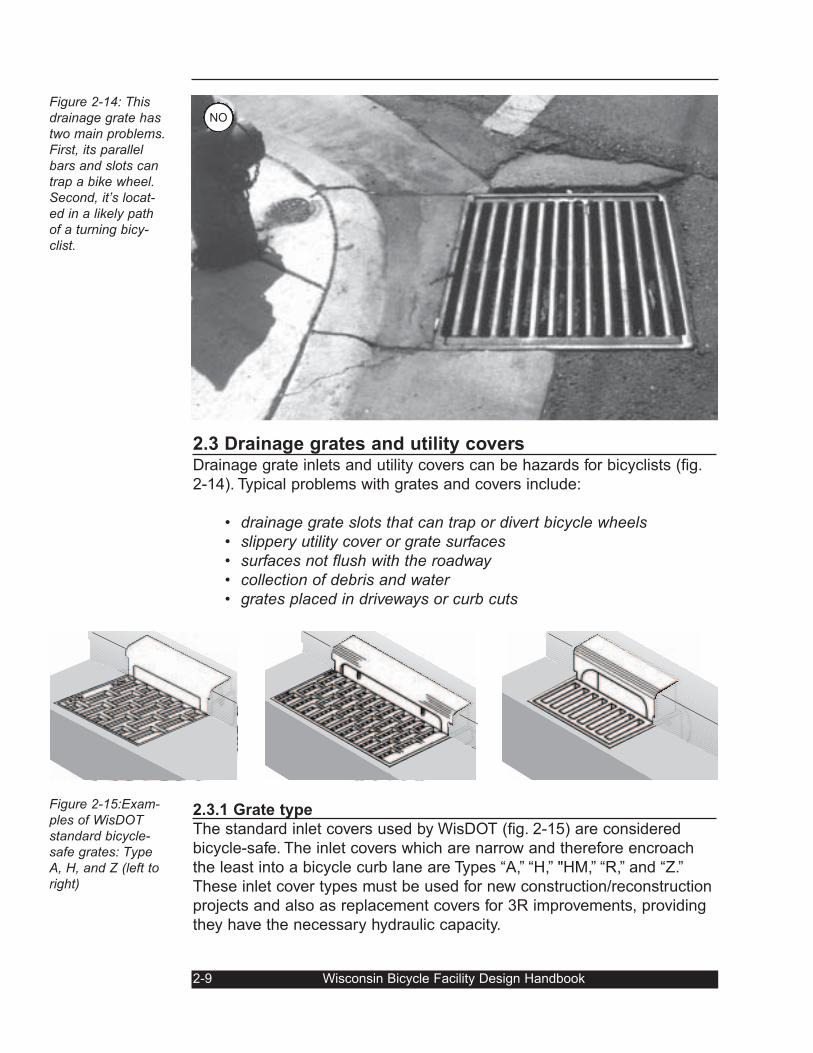
2.3 Drainage grates and utility coversDrainage grate inlets and utility covers can be hazards for bicyclists (fig.
2-14). Typical problems with grates and covers include:
• drainage grate slots that can trap or divert bicycle wheels• slippery utility cover or grate surfaces• surfaces not flush with the roadway• collection of debris and water• grates placed in driveways or curb cuts
2.3.1 Grate type
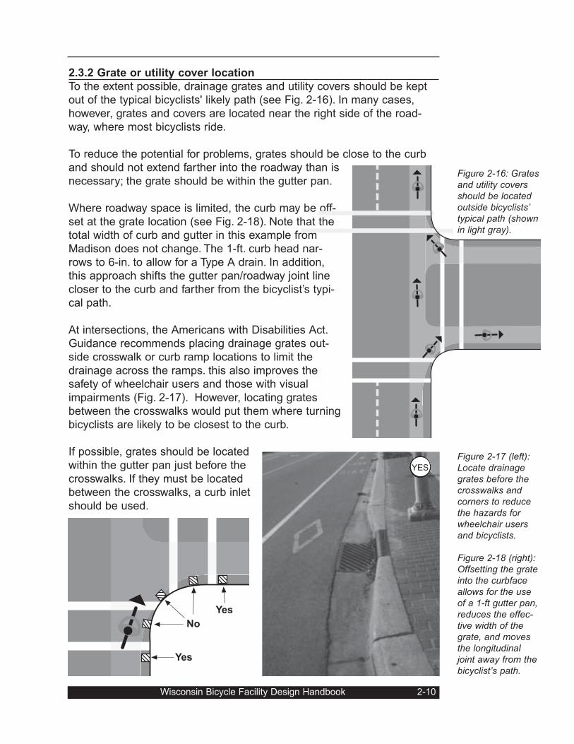
The standard inlet covers used by WisDOT (fig. 2-15) are considered
bicycle-safe. The inlet covers which are narrow and therefore encroach
the least into a bicycle curb lane are Types “A,” “H,” "HM,” “R,” and “Z.”
These inlet cover types must be used for new construction/reconstruction
projects and also as replacement covers for 3R improvements, providing
they have the necessary hydraulic capacity.
2-9 Wisconsin Bicycle Facility Design Handbook
Figure 2-14: Thisdrainage grate hastwo main problems.First, its parallelbars and slots cantrap a bike wheel.Second, it’s locat-ed in a likely pathof a turning bicy-clist.
Figure 2-15:Exam-ples of WisDOTstandard bicycle-safe grates: TypeA, H, and Z (left toright)
NO
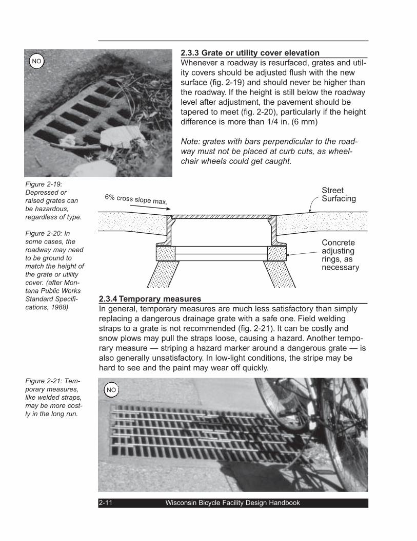
2.3.2 Grate or utility cover location
To the extent possible, drainage grates and utility covers should be kept
out of the typical bicyclists' likely path (see Fig. 2-16). In many cases,
however, grates and covers are located near the right side of the road-
way, where most bicyclists ride.
To reduce the potential for problems, grates should be close to the curb
and should not extend farther into the roadway than is
necessary; the grate should be within the gutter pan.
Where roadway space is limited, the curb may be off-
set at the grate location (see Fig. 2-18). Note that the
total width of curb and gutter in this example from
Madison does not change. The 1-ft. curb head nar-
rows to 6-in. to allow for a Type A drain. In addition,
this approach shifts the gutter pan/roadway joint line
closer to the curb and farther from the bicyclist’s typi-
cal path.
At intersections, the Americans with Disabilities Act.
Guidance recommends placing drainage grates out-
side crosswalk or curb ramp locations to limit the
drainage across the ramps. this also improves the
safety of wheelchair users and those with visual
impairments (Fig. 2-17). However, locating grates
between the crosswalks would put them where turning
bicyclists are likely to be closest to the curb.
If possible, grates should be located
within the gutter pan just before the
crosswalks. If they must be located
between the crosswalks, a curb inlet
should be used.
Wisconsin Bicycle Facility Design Handbook 2-10
No
Yes
Yes
Figure 2-16: Gratesand utility coversshould be locatedoutside bicyclists’typical path (shownin light gray).
Figure 2-17 (left):Locate drainagegrates before thecrosswalks andcorners to reducethe hazards forwheelchair usersand bicyclists.
Figure 2-18 (right):Offsetting the grateinto the curbfaceallows for the useof a 1-ft gutter pan,reduces the effec-tive width of thegrate, and movesthe longitudinaljoint away from thebicyclist’s path.
YES
2.3.3 Grate or utility cover elevation
Whenever a roadway is resurfaced, grates and util-
ity covers should be adjusted flush with the new
surface (fig. 2-19) and should never be higher than
the roadway. If the height is still below the roadway
level after adjustment, the pavement should be
tapered to meet (fig. 2-20), particularly if the height
difference is more than 1/4 in. (6 mm)
Note: grates with bars perpendicular to the road-way must not be placed at curb cuts, as wheel-chair wheels could get caught.
2.3.4 Temporary measures
In general, temporary measures are much less satisfactory than simply
replacing a dangerous drainage grate with a safe one. Field welding
straps to a grate is not recommended (fig. 2-21). It can be costly and
snow plows may pull the straps loose, causing a hazard. Another tempo-
rary measure — striping a hazard marker around a dangerous grate — is
also generally unsatisfactory. In low-light conditions, the stripe may be
hard to see and the paint may wear off quickly.
2-11 Wisconsin Bicycle Facility Design Handbook
Figure 2-19:Depressed orraised grates canbe hazardous,regardless of type.
Figure 2-20: Insome cases, theroadway may needto be ground tomatch the height ofthe grate or utilitycover. (after Mon-tana Public WorksStandard Specifi-cations, 1988)
Figure 2-21: Tem-porary measures,like welded straps,may be more cost-ly in the long run.
StreetSurfacing
Concreteadjustingrings, asnecessary
6% cross slope max.
NO
NO
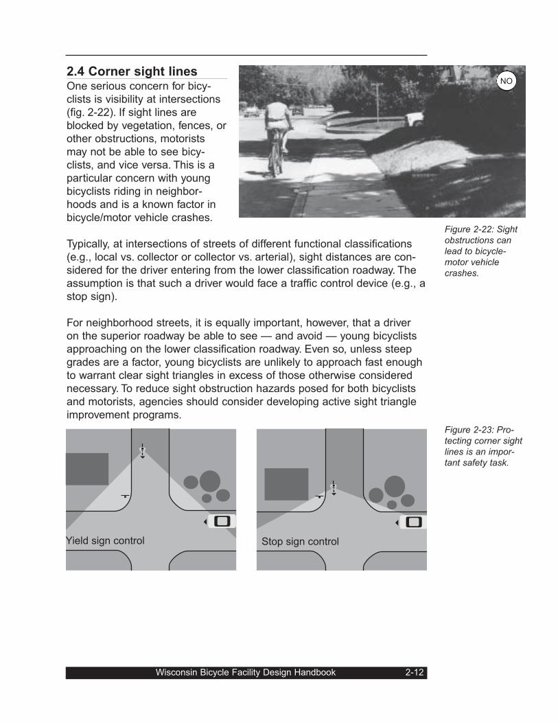
2.4 Corner sight linesOne serious concern for bicy-
clists is visibility at intersections
(fig. 2-22). If sight lines are
blocked by vegetation, fences, or
other obstructions, motorists
may not be able to see bicy-
clists, and vice versa. This is a
particular concern with young
bicyclists riding in neighbor-
hoods and is a known factor in
bicycle/motor vehicle crashes.
Typically, at intersections of streets of different functional classifications
(e.g., local vs. collector or collector vs. arterial), sight distances are con-
sidered for the driver entering from the lower classification roadway. The
assumption is that such a driver would face a traffic control device (e.g., a
stop sign).
For neighborhood streets, it is equally important, however, that a driver
on the superior roadway be able to see — and avoid — young bicyclists
approaching on the lower classification roadway. Even so, unless steep
grades are a factor, young bicyclists are unlikely to approach fast enough
to warrant clear sight triangles in excess of those otherwise considered
necessary. To reduce sight obstruction hazards posed for both bicyclists
and motorists, agencies should consider developing active sight triangle
improvement programs.
Wisconsin Bicycle Facility Design Handbook 2-12
Figure 2-22: Sightobstructions canlead to bicycle-motor vehiclecrashes.
Figure 2-23: Pro-tecting corner sightlines is an impor-tant safety task.
Yield sign control Stop sign control
NO
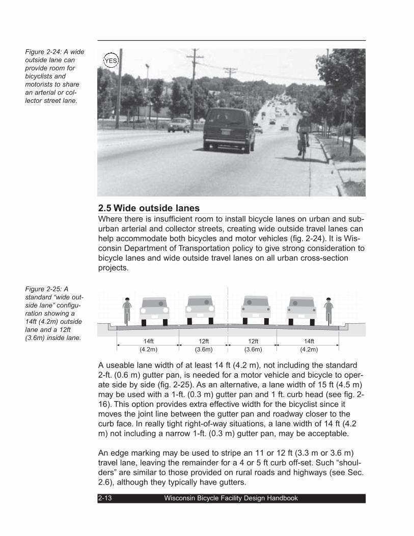
2.5 Wide outside lanesWhere there is insufficient room to install bicycle lanes on urban and sub-
urban arterial and collector streets, creating wide outside travel lanes can
help accommodate both bicycles and motor vehicles (fig. 2-24). It is Wis-
consin Department of Transportation policy to give strong consideration to
bicycle lanes and wide outside travel lanes on all urban cross-section
projects.
A useable lane width of at least 14 ft (4.2 m), not including the standard
2-ft. (0.6 m) gutter pan, is needed for a motor vehicle and bicycle to oper-
ate side by side (fig. 2-25). As an alternative, a lane width of 15 ft (4.5 m)
may be used with a 1-ft. (0.3 m) gutter pan and 1 ft. curb head (see fig. 2-
16). This option provides extra effective width for the bicyclist since it
moves the joint line between the gutter pan and roadway closer to the
curb face. In really tight right-of-way situations, a lane width of 14 ft (4.2
m) not including a narrow 1-ft. (0.3 m) gutter pan, may be acceptable.
An edge marking may be used to stripe an 11 or 12 ft (3.3 m or 3.6 m)
travel lane, leaving the remainder for a 4 or 5 ft curb off-set. Such “shoul-
ders” are similar to those provided on rural roads and highways (see Sec.
2.6), although they typically have gutters.
2-13 Wisconsin Bicycle Facility Design Handbook
Figure 2-24: A wideoutside lane canprovide room forbicyclists andmotorists to sharean arterial or col-lector street lane.
Figure 2-25: Astandard “wide out-side lane” configu-ration showing a14ft (4.2m) outsidelane and a 12ft(3.6m) inside lane.
14ft
(4.2m)
14ft
(4.2m)
12ft
(3.6m)
12ft
(3.6m)
YES
In some instances, widths greater than 15 ft (4.5m) can encourage the
operation of two motor vehicles in one lane, although this is not a com-
mon problem in Wisconsin. This is most likely to occur near intersections
with heavy turn volumes at times of maximum congestion and lowest
speeds. Such conditions may reflect a need to consider modifications to
the intersection. On streets with dedicated right-turn lanes, the right-most
through lane should be widened.
Wide outside lanes have numerous benefits in addition to providing space
for bicyclists and motorists to share. They improve roadway capacity by
reducing conflicts between motorists traveling straight and those turning
into or out of driveways and cross streets. And they provide space for
temporary storage of snow and disabled motor vehicles.
If on-street parking is provided along
with the wide outside travel lane, the
parking lane should be standard width.
Narrowing a parking lane to provide the
space for bicyclists may or may not
encourage motorists to park closer to
the curb (fig. 2-27). If a standard travel
lane is used, a total of 12 ft (3.6 m) of
combined parking/bicycling space is
highly recommended for this type of
shared use.
And an opening car door may take up
the extra space in the travel lane. As a
result, the effective width of the outside
travel lane in such cases may not be as
great as the measured width.
Wisconsin Bicycle Facility Design Handbook 2-14
Figure 2-26: Wideoutside lanes pro-vide clearance formotorists enteringdriveways or crossstreets or waitingto leave them.
Figure 2-27: Nar-rowing the parkinglane by adding awhite line willnot necessarily cre-ate extra space forbicyclists.
14 ft
(4.2m)
14ft
(4.2m)
12ft
(3.6m)
12ft
(3.6m)
Note: wide lanes are not suggested for quiet residential streets, wherethey are unnecessary, increase construction costs, and may increase“cut-through” traffic speeds.
NO
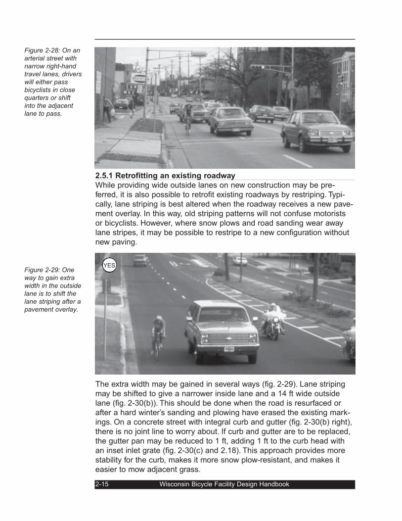
2.5.1 Retrofitting an existing roadway
While providing wide outside lanes on new construction may be pre-
ferred, it is also possible to retrofit existing roadways by restriping. Typi-
cally, lane striping is best altered when the roadway receives a new pave-
ment overlay. In this way, old striping patterns will not confuse motorists
or bicyclists. However, where snow plows and road sanding wear away
lane stripes, it may be possible to restripe to a new configuration without
new paving.
The extra width may be gained in several ways (fig. 2-29). Lane striping
may be shifted to give a narrower inside lane and a 14 ft wide outside
lane (fig. 2-30(b)). This should be done when the road is resurfaced or
after a hard winter’s sanding and plowing have erased the existing mark-
ings. On a concrete street with integral curb and gutter (fig. 2-30(b) right),
there is no joint line to worry about. If curb and gutter are to be replaced,
the gutter pan may be reduced to 1 ft, adding 1 ft to the curb head with
an inset inlet grate (fig. 2-30(c) and 2.18). This approach provides more
stability for the curb, makes it more snow plow-resistant, and makes it
easier to mow adjacent grass.
2-15 Wisconsin Bicycle Facility Design Handbook
Figure 2-28: On anarterial street withnarrow right-handtravel lanes, driverswill either passbicyclists in closequarters or shiftinto the adjacentlane to pass.
Figure 2-29: Oneway to gain extrawidth in the outsidelane is to shift thelane striping after apavement overlay.
YES
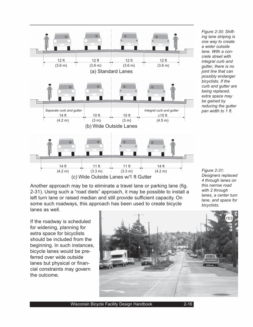
Another approach may be to eliminate a travel lane or parking lane (fig.
2-31). Using such a “road diets” approach, it may be possible to install a
left turn lane or raised median and still provide sufficient capacity. On
some such roadways, this approach has been used to create bicycle
lanes as well.
If the roadway is scheduled
for widening, planning for
extra space for bicyclists
should be included from the
beginning. In such instances,
bicycle lanes would be pre-
ferred over wide outside
lanes but physical or finan-
cial constraints may govern
the outcome.
Wisconsin Bicycle Facility Design Handbook 2-16
Figure 2-30: Shift-ing lane striping isone way to createa wider outsidelane. With a con-crete street withintegral curb andgutter, there is nojoint line that canpossibly endangerbicyclists. If thecurb and gutter arebeing replaced,extra space maybe gained byreducing the gutterpan width to 1 ft.
Figure 2-31:Designers replaced4 through lanes onthis narrow roadwith 2 throughlanes, a center turnlane, and space forbicyclists.
12 ft
(3.6 m)
12 ft
(3.6 m)
12 ft
(3.6 m)
12 ft
(3.6 m)
(a) Standard Lanes
14 ft
(4.2 m)
≥15 ft
(4.5 m)
10 ft
(3 m)
10 ft
(3 m)
(b) Wide Outside Lanes
Separate curb and gutter Integral curb and gutter
14 ft
(4.2 m)
14 ft
(4.2 m)
11 ft
(3.3 m)
11 ft
(3.3 m)
(c) Wide Outside Lanes w/1 ft Gutter
YES
2.6 Paved shouldersOn rural highways, smoothly paved shoulders are preferred by many
bicyclists. Shoulders provide clearance between bicyclists and high-speed
motor vehicle traffic and they reduce the “wind blast” effect of passing
trucks. In addition, there are other reasons for considering shoulders.
According to The Policy on Geometric Design of Highways and Streets(AASHTO, 2001), paved or stabilized shoulders provide:
• usable area for vehicles to pull onto during emergencies;• elimination of rutting adjacent to the edge of travel lane;• adequate cross slope for drainage of roadway;• reduced maintenance; and• lateral support for roadway base and surface course.
2.6.1 Low-volume rural roads
Very-low-volume rural roads (i.e., those with ADT’s below 700) seldom
require special provisions like paved shoul-
ders for bicyclists (fig. 2-33). A motorist
needing to move left to pass a bicyclist is
unlikely to face oncoming traffic and may
simply shift over. And bicyclists can ride far
enough from the pavement edge to avoid
hazards.
In special cases, shoulders may be benefi-
cial (e.g., on a town road connecting a
school and a nearby rural neighborhood or a
hilly low-volume highway serving truck traf-
fic). Generally, on busier rural routes, like
2-17 Wisconsin Bicycle Facility Design Handbook
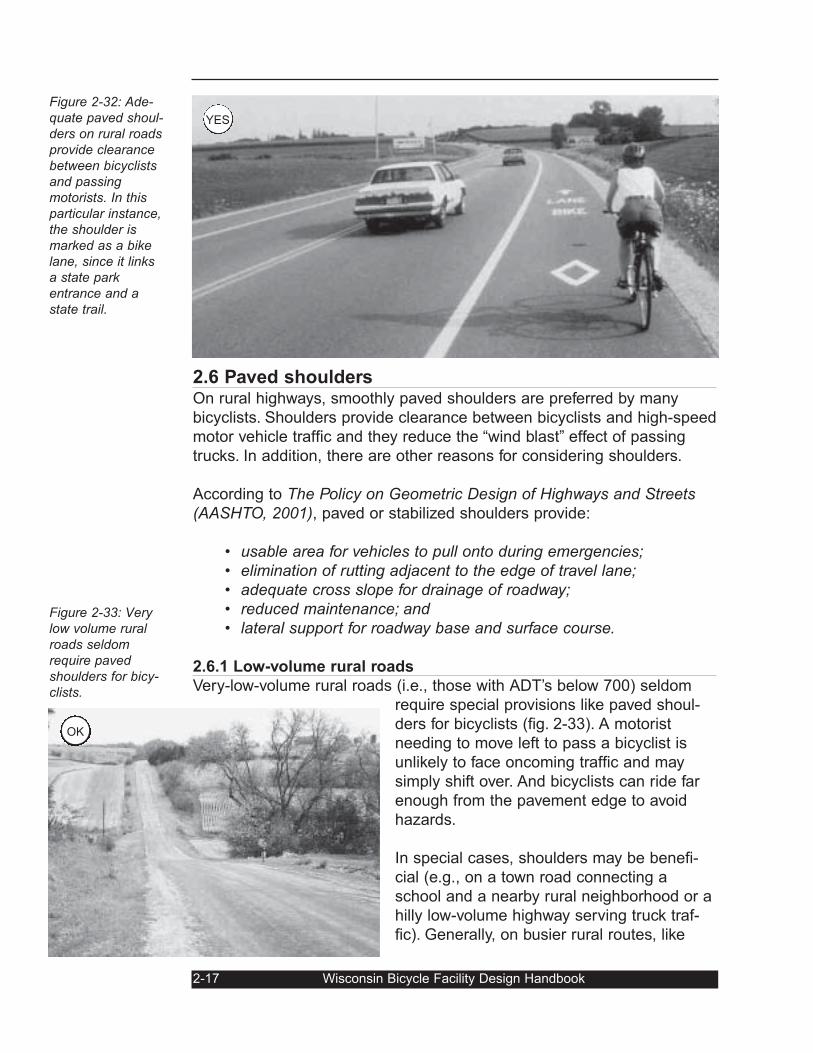
Figure 2-32: Ade-quate paved shoul-ders on rural roadsprovide clearancebetween bicyclistsand passingmotorists. In thisparticular instance,the shoulder ismarked as a bikelane, since it linksa state parkentrance and astate trail.
Figure 2-33: Verylow volume ruralroads seldomrequire pavedshoulders for bicy-clists.
OK
YES
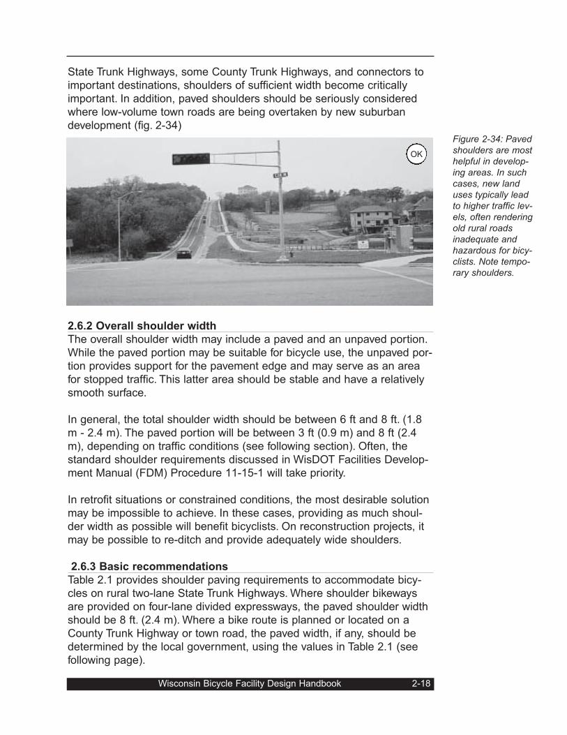
Figure 2-34: Pavedshoulders are mosthelpful in develop-ing areas. In suchcases, new landuses typically leadto higher traffic lev-els, often renderingold rural roadsinadequate andhazardous for bicy-clists. Note tempo-rary shoulders.
State Trunk Highways, some County Trunk Highways, and connectors to
important destinations, shoulders of sufficient width become critically
important. In addition, paved shoulders should be seriously considered
where low-volume town roads are being overtaken by new suburban
development (fig. 2-34)
2.6.2 Overall shoulder width
The overall shoulder width may include a paved and an unpaved portion.
While the paved portion may be suitable for bicycle use, the unpaved por-
tion provides support for the pavement edge and may serve as an area
for stopped traffic. This latter area should be stable and have a relatively
smooth surface.
In general, the total shoulder width should be between 6 ft and 8 ft. (1.8
m - 2.4 m). The paved portion will be between 3 ft (0.9 m) and 8 ft (2.4
m), depending on traffic conditions (see following section). Often, the
standard shoulder requirements discussed in WisDOT Facilities Develop-
ment Manual (FDM) Procedure 11-15-1 will take priority.
In retrofit situations or constrained conditions, the most desirable solution
may be impossible to achieve. In these cases, providing as much shoul-
der width as possible will benefit bicyclists. On reconstruction projects, it
may be possible to re-ditch and provide adequately wide shoulders.
2.6.3 Basic recommendations
Table 2.1 provides shoulder paving requirements to accommodate bicy-
cles on rural two-lane State Trunk Highways. Where shoulder bikeways
are provided on four-lane divided expressways, the paved shoulder width
should be 8 ft. (2.4 m). Where a bike route is planned or located on a
County Trunk Highway or town road, the paved width, if any, should be
determined by the local government, using the values in Table 2.1 (see
following page).
Wisconsin Bicycle Facility Design Handbook 2-18
OK
While Table 2.1 provides general guidance, more detailed analysis should
be considered when preparing a bicycle plan or where specific roadway
conditions are more complicated than normal. To this end, the Depart-
ment has produced several reports that should be of assistance:
On almost all state highway projects involving reconditioning or recon-
struction, paved shoulders will be part of the project. Planners and engi-
neers need to consider the width of the paved shoulder by examining the
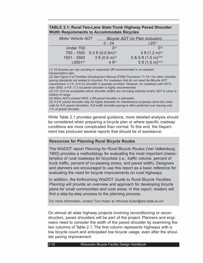
two columns of Table 2.1. The first column represents highways with a
low bicycle count and anticipated low bicycle usage, even after the shoul-
der paving improvement.
2-19 Wisconsin Bicycle Facility Design Handbook
Resources for Planning Rural Bicycle Routes
The WisDOT report Planning for Rural Bicycle Routes (Van Valkenburg,
1993) provides a methodology for evaluating the most important charac-
teristics of rural roadways for bicyclists (i.e., traffic volume, percent of
truck traffic, percent of no-passing zones, and paved width). Designers
and planners are encouraged to use this report as a basic reference for
evaluating the need for bicycle improvements on rural highways.
In addition, the forthcoming WisDOT Guide to Rural Bicycle FacilitiesPlanning will provide an overview and approach for developing bicycle
plans for small communities and rural areas. In this report, readers will
find a step-by-step process to the planning process.
For more information, contact Tom Huber at <[email protected]>
TABLE 2.1: Rural Two-Lane State Trunk Highway Paved Shoulder
Width Requirements to Accommodate Bicycles
Motor Vehicle ADT Bicycle ADT (or Plan inclusion) 0 - 24 ≥25(1)
Under 700 0(2) 0(2)
700 - 1500 0-3 ft (0-0.9m)(2) 4 ft (1.2 m)(3)
1501 - 3500 3 ft (0.9 m)(2) 5 & 6 ft (1.5 m)(2)(5)
≥3501(4) 4 ft(2) 5 ft (1.5 m)(2)(4)
(1) 25 bicycles per day (existing or expected) OR recommended in an adopted transportation plan.(2) See Figure 5 of Facilities Development Manual (FDM) Procedure 11-15-1 for other shoulderpaving standards not related to bicycles. For roadways that do not meet the Bicycle ADTrequirement, a 3 ft. (0.9 m) shoulder is typically provided. However, for roadways with ADTsover 3500, a 4 ft. (1.2 m) paved shoulder is highly recommended.(3) 3 ft. (0.9 m) acceptable where shoulder widths are not being widened and/or ADT is close tobottom of range.(4) When ADTs exceed 4500, a 6ft paved shoulder is advisable.(5) A 6 ft. paved shoulder may be highly desirable for maintenance purposes since this classcalls for 6 ft. gravel shoulders. Full width shoulder paving is often preferred over leaving only1 ft. of gravel shoulder.
The second column indicates a moderate level of current or anticipated
bike use (25 cyclists or more per day during peak periods). This column
should be used under the following situations:
• A bicycle transportation plan (e.g., the Wisconsin BicycleTransportation Plan, county bicycle transportation plans, orregional bicycle transportation plans) identifies a highway seg-ment as needing wider paved shoulders;
• A bicycle use survey has determined there are 25 bicyclistsper day using the highway;
• Likely bicycle traffic generators (e.g., schools, businesses,subdivisions, parks, etc.) have been built or expected to bebuilt along the stretch of highway;
• A highway project stretches between the built-up area of a vil-lage or city and an intersecting town or county road. In mostcases, bicycle travel will be heaviest between the city/villagelimits and the nearest town or county road. Paving widershoulders (using column 2) for just this segment provides asafer means for bicyclists to access the town and/or countyroad system.
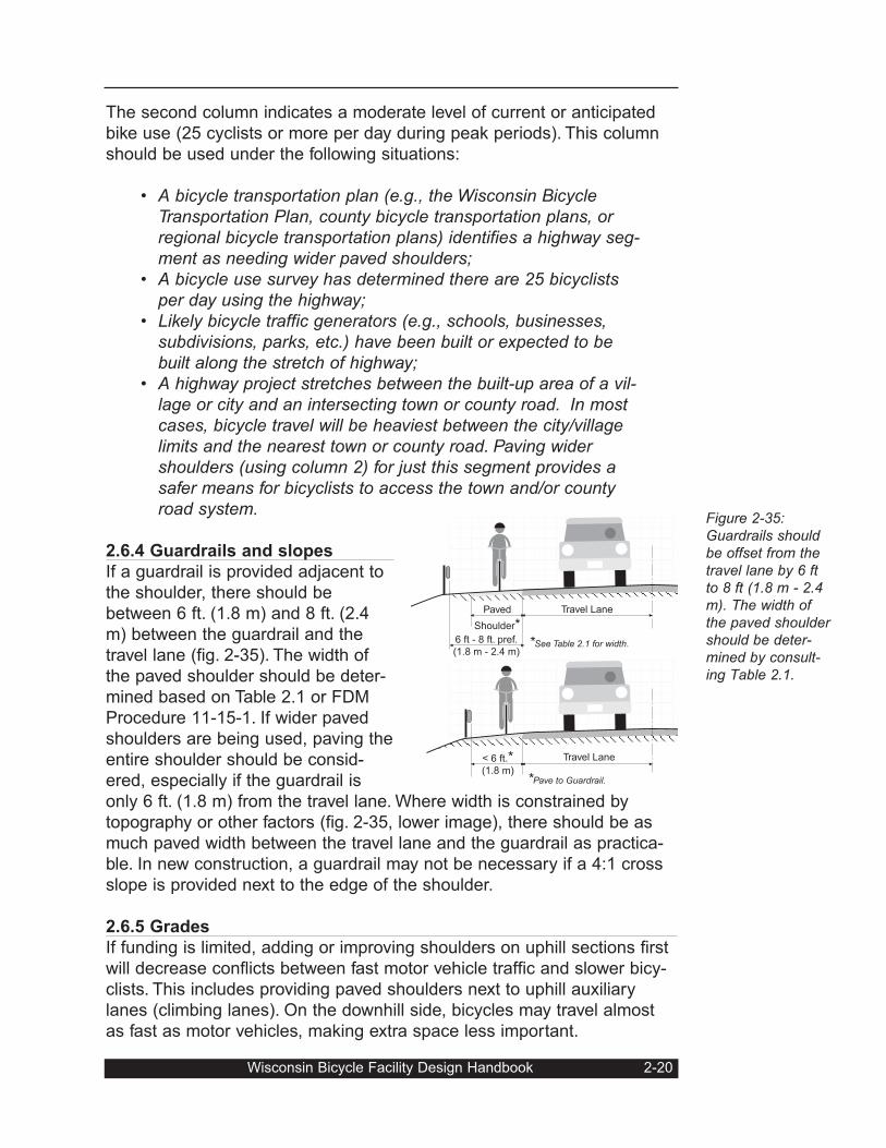
2.6.4 Guardrails and slopes
If a guardrail is provided adjacent to
the shoulder, there should be
between 6 ft. (1.8 m) and 8 ft. (2.4
m) between the guardrail and the
travel lane (fig. 2-35). The width of
the paved shoulder should be deter-
mined based on Table 2.1 or FDM
Procedure 11-15-1. If wider paved
shoulders are being used, paving the
entire shoulder should be consid-
ered, especially if the guardrail is
only 6 ft. (1.8 m) from the travel lane. Where width is constrained by
topography or other factors (fig. 2-35, lower image), there should be as
much paved width between the travel lane and the guardrail as practica-
ble. In new construction, a guardrail may not be necessary if a 4:1 cross
slope is provided next to the edge of the shoulder.
2.6.5 Grades
If funding is limited, adding or improving shoulders on uphill sections first
will decrease conflicts between fast motor vehicle traffic and slower bicy-
clists. This includes providing paved shoulders next to uphill auxiliary
lanes (climbing lanes). On the downhill side, bicycles may travel almost
as fast as motor vehicles, making extra space less important.
Wisconsin Bicycle Facility Design Handbook 2-20
Figure 2-35:Guardrails shouldbe offset from thetravel lane by 6 ftto 8 ft (1.8 m - 2.4m). The width ofthe paved shouldershould be deter-mined by consult-ing Table 2.1.
Paved
Shoulder*Travel Lane
Travel Lane< 6 ft.*(1.8 m)
6 ft - 8 ft. pref.
(1.8 m - 2.4 m)*See Table 2.1 for width.
*Pave to Guardrail.
2.6.6 Pavement design and loading
Shoulders should be smoothly paved and have adequate strength and
stability to support occasional motor vehicle tire loads under all weather
conditions without rutting or other surface variations. The thickness of
shoulder paving should be based on usual design considerations appro-
priate for each situation, although full-depth pavement is recommended.
2.6.7 Joints between travel lanes and shoulders
Where it is necessary to add paved shoulders to existing roadways for
bicycle use, the area where bicyclists will be riding should be kept free of
joint lines. If a wider shoulder (i.e., 8 ft.) is being provided, the joint line
will not likely be a serious problem. However, if a narrow shoulder is
being added, it is desirable to provide a minimum of 4 ft. (1.2 m) of clear
width without a longitudinal joint line.
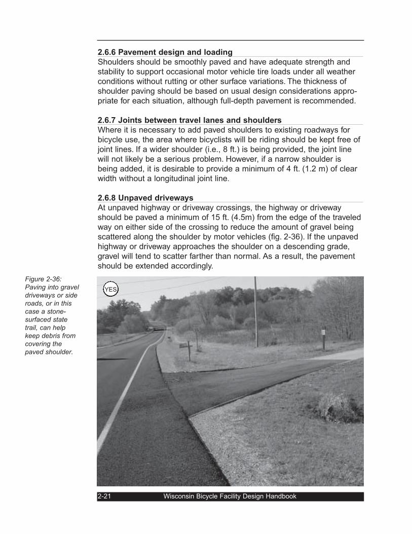
2.6.8 Unpaved driveways
At unpaved highway or driveway crossings, the highway or driveway
should be paved a minimum of 15 ft. (4.5m) from the edge of the traveled
way on either side of the crossing to reduce the amount of gravel being
scattered along the shoulder by motor vehicles (fig. 2-36). If the unpaved
highway or driveway approaches the shoulder on a descending grade,
gravel will tend to scatter farther than normal. As a result, the pavement
should be extended accordingly.
2-21 Wisconsin Bicycle Facility Design Handbook
Figure 2-36:Paving into graveldriveways or sideroads, or in thiscase a stone-surfaced state trail, can help keep debris fromcovering thepaved shoulder.
YES
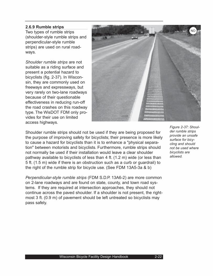
2.6.9 Rumble strips
Two types of rumble strips
(shoulder-style rumble strips and
perpendicular-style rumble
strips) are used on rural road-
ways.
Shoulder rumble strips are not
suitable as a riding surface and
present a potential hazard to
bicyclists (fig. 2-37). In Wiscon-
sin, they are commonly used on
freeways and expressways, but
very rarely on two-lane roadways
because of their questionable
effectiveness in reducing run-off
the road crashes on this roadway
type. The WisDOT FDM only pro-
vides for their use on limited
access highways.
Shoulder rumble strips should not be used if they are being proposed for
the purpose of improving safety for bicyclists; their presence is more likely
to cause a hazard for bicyclists than it is to enhance a "physical separa-
tion" between motorists and bicyclists. Furthermore, rumble strips should
not normally be used if their installation would leave a clear shoulder
pathway available to bicyclists of less than 4 ft. (1.2 m) wide (or less than
5 ft. (1.5 m) wide if there is an obstruction such as a curb or guardrail) to
the right of the rumble strip for bicycle use. (See FDM 13A5-3a & b)
Perpendicular-style rumble strips (FDM S.D.P. 13A6-2) are more common
on 2-lane roadways and are found on state, county, and town road sys-
tems. If they are required at intersection approaches, they should not
continue across the paved shoulder. If a shoulder is not present, the right-
most 3 ft. (0.9 m) of pavement should be left untreated so bicyclists may
pass safely.
Wisconsin Bicycle Facility Design Handbook 2-22
Figure 2-37: Shoul-der rumble stripsprovide an unsafesurface for bicy-cling and shouldnot be used wherebicyclists areallowed.
NO
2.7 Railroad crossingsSpecial care should be taken wherever a roadway or path crosses rail-
road tracks at grade. Numerous bicycle crashes have resulted from dan-
gerous crossings. The most important crossing features for bicyclists are
(1) the crossing angle and the presence of a gap on either side of the
track’s rail; and (2) the crossing’s smoothness. Problems with both of
these features are illustrated in figure 2-38.
2.7.1 Crossing angles and gaps
Railroad crossings should ideally be straight and at a 90-degree angle to
the rails. The more the crossing deviates from this ideal angle, the greater
is the potential for a bicyclist's front wheel to be diverted by the gap on
either side of the rail — or even by the rail, itself. Crossing angles of 30
degrees or less are considered exceptionally hazardous, particularly
when wet. However, if the crossing angle is less than approximately 60
degrees, remedial action should be considered.
2-23 Wisconsin Bicycle Facility Design Handbook
Roadway RoadwayCrossing Panel
GaugeFlangeway
FieldFlangeway
Rail Rail
Potentiallydangerous gaps
TrainWheel
Fig. 2-38: An oldunused diagonalrailroad crossing.The flangeway cancatch and turn abicyclist’s frontwheel, especiallywhen wet, and theroughness can alsocause a tumble.
Fig. 2-39: Basicstructure of a rail-road crossing.
NO
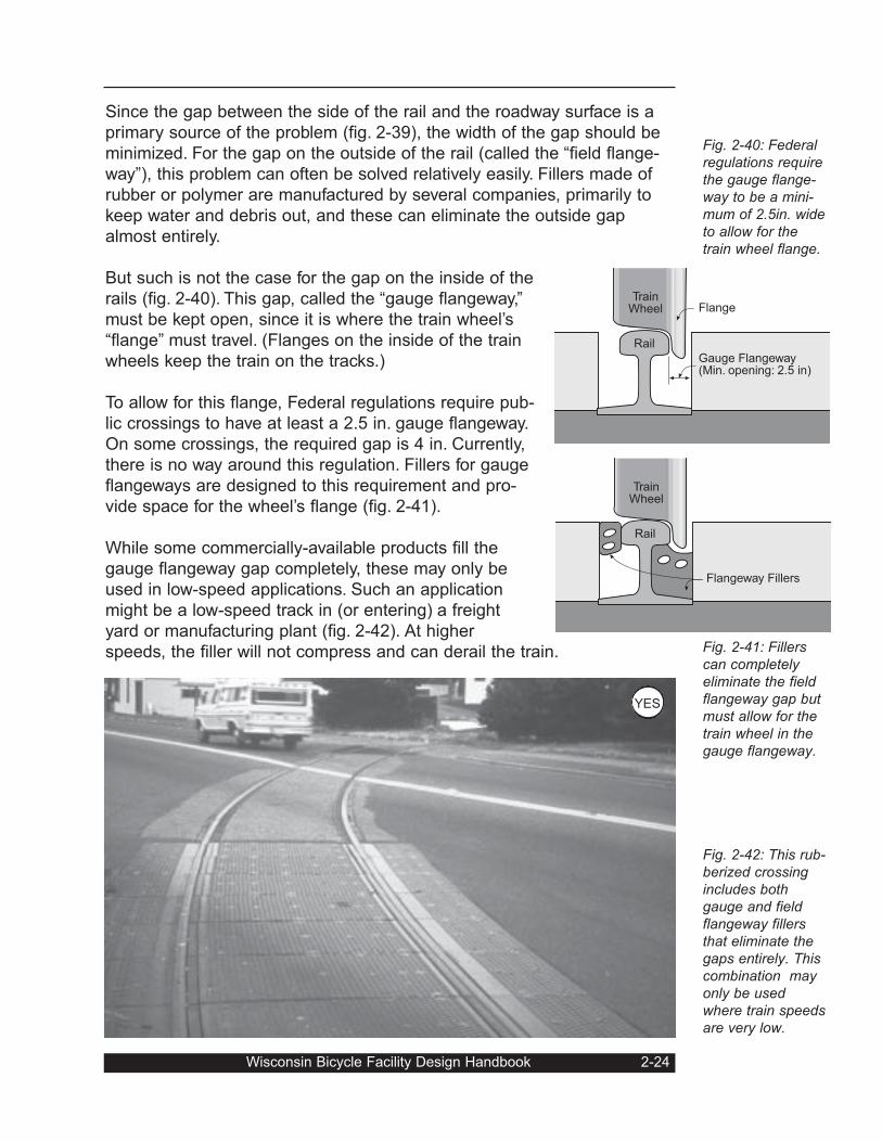
Since the gap between the side of the rail and the roadway surface is a
primary source of the problem (fig. 2-39), the width of the gap should be
minimized. For the gap on the outside of the rail (called the “field flange-
way”), this problem can often be solved relatively easily. Fillers made of
rubber or polymer are manufactured by several companies, primarily to
keep water and debris out, and these can eliminate the outside gap
almost entirely.
But such is not the case for the gap on the inside of the
rails (fig. 2-40). This gap, called the “gauge flangeway,”
must be kept open, since it is where the train wheel’s
“flange” must travel. (Flanges on the inside of the train
wheels keep the train on the tracks.)
To allow for this flange, Federal regulations require pub-
lic crossings to have at least a 2.5 in. gauge flangeway.
On some crossings, the required gap is 4 in. Currently,
there is no way around this regulation. Fillers for gauge
flangeways are designed to this requirement and pro-
vide space for the wheel’s flange (fig. 2-41).
While some commercially-available products fill the
gauge flangeway gap completely, these may only be
used in low-speed applications. Such an application
might be a low-speed track in (or entering) a freight
yard or manufacturing plant (fig. 2-42). At higher
speeds, the filler will not compress and can derail the train.
Wisconsin Bicycle Facility Design Handbook 2-24
Fig. 2-40: Federalregulations requirethe gauge flange-way to be a mini-mum of 2.5in. wideto allow for thetrain wheel flange.
Fig. 2-41: Fillerscan completelyeliminate the fieldflangeway gap butmust allow for thetrain wheel in thegauge flangeway.
Fig. 2-42: This rub-berized crossingincludes bothgauge and fieldflangeway fillersthat eliminate thegaps entirely. Thiscombination mayonly be usedwhere train speedsare very low.
Rail
TrainWheel
Gauge Flangeway(Min. opening: 2.5 in)
Flange
Rail
Flangeway Fillers
TrainWheel
YES
While the flangeway
problem on diagonal
crossings may be par-
tially solved with fillers,
in general such solu-
tions can only address
the field flangeway part
of the problem. At the
same time, smooth
installations using con-
crete and/or rubber can
reduce the hazard by
making the crossing
more level and uniform
(see Sec. 2.7.2).
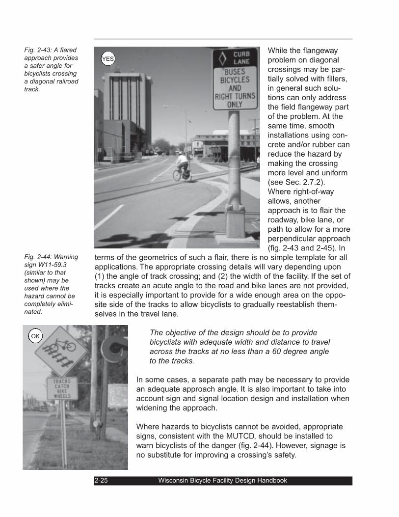
Where right-of-way
allows, another
approach is to flair the
roadway, bike lane, or
path to allow for a more
perpendicular approach
(fig. 2-43 and 2-45). In
terms of the geometrics of such a flair, there is no simple template for all
applications. The appropriate crossing details will vary depending upon
(1) the angle of track crossing; and (2) the width of the facility. If the set of
tracks create an acute angle to the road and bike lanes are not provided,
it is especially important to provide for a wide enough area on the oppo-
site side of the tracks to allow bicyclists to gradually reestablish them-
selves in the travel lane.
The objective of the design should be to provide bicyclists with adequate width and distance to travel across the tracks at no less than a 60 degree angle to the tracks.
In some cases, a separate path may be necessary to provide
an adequate approach angle. It is also important to take into
account sign and signal location design and installation when
widening the approach.
Where hazards to bicyclists cannot be avoided, appropriate
signs, consistent with the MUTCD, should be installed to
warn bicyclists of the danger (fig. 2-44). However, signage is
no substitute for improving a crossing’s safety.
2-25 Wisconsin Bicycle Facility Design Handbook
Fig. 2-43: A flaredapproach providesa safer angle forbicyclists crossinga diagonal railroadtrack.
Fig. 2-44: Warningsign W11-59.3(similar to thatshown) may beused where thehazard cannot becompletely elimi-nated.
OK
YES
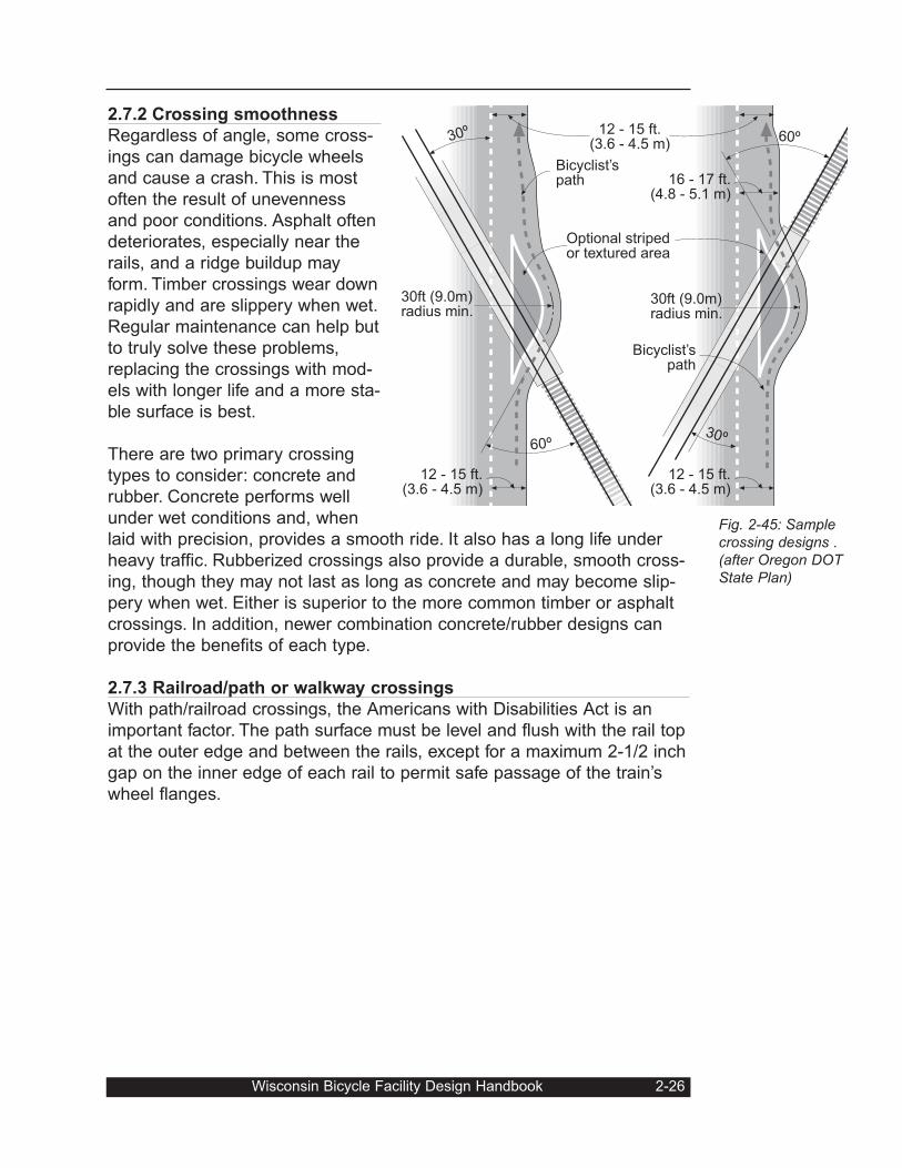
2.7.2 Crossing smoothness
Regardless of angle, some cross-
ings can damage bicycle wheels
and cause a crash. This is most
often the result of unevenness
and poor conditions. Asphalt often
deteriorates, especially near the
rails, and a ridge buildup may
form. Timber crossings wear down
rapidly and are slippery when wet.
Regular maintenance can help but
to truly solve these problems,
replacing the crossings with mod-
els with longer life and a more sta-
ble surface is best.
There are two primary crossing
types to consider: concrete and
rubber. Concrete performs well
under wet conditions and, when
laid with precision, provides a smooth ride. It also has a long life under
heavy traffic. Rubberized crossings also provide a durable, smooth cross-
ing, though they may not last as long as concrete and may become slip-
pery when wet. Either is superior to the more common timber or asphalt
crossings. In addition, newer combination concrete/rubber designs can
provide the benefits of each type.
2.7.3 Railroad/path or walkway crossings
With path/railroad crossings, the Americans with Disabilities Act is an
important factor. The path surface must be level and flush with the rail top
at the outer edge and between the rails, except for a maximum 2-1/2 inch
gap on the inner edge of each rail to permit safe passage of the train’s
wheel flanges.
Wisconsin Bicycle Facility Design Handbook 2-26
60º
30º
30ft (9.0m)radius min.
12 - 15 ft.(3.6 - 4.5 m)
60º
30º
30ft (9.0m)radius min.
Bicyclist’spath
Optional stripedor textured area
12 - 15 ft.(3.6 - 4.5 m)
12 - 15 ft.(3.6 - 4.5 m)
16 - 17 ft.(4.8 - 5.1 m)
Bicyclist’spath
Fig. 2-45: Samplecrossing designs .(after Oregon DOTState Plan)
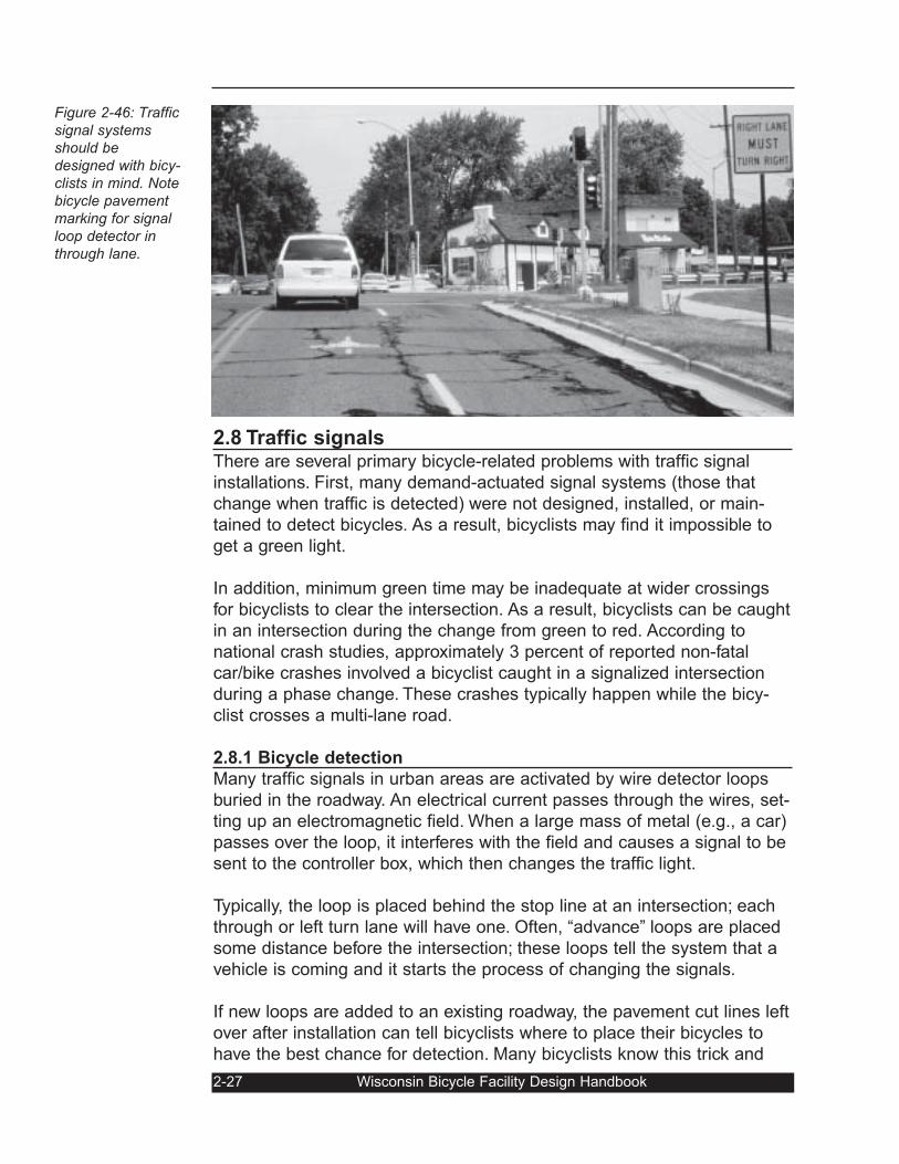
2.8 Traffic signalsThere are several primary bicycle-related problems with traffic signal
installations. First, many demand-actuated signal systems (those that
change when traffic is detected) were not designed, installed, or main-
tained to detect bicycles. As a result, bicyclists may find it impossible to
get a green light.
In addition, minimum green time may be inadequate at wider crossings
for bicyclists to clear the intersection. As a result, bicyclists can be caught
in an intersection during the change from green to red. According to
national crash studies, approximately 3 percent of reported non-fatal
car/bike crashes involved a bicyclist caught in a signalized intersection
during a phase change. These crashes typically happen while the bicy-
clist crosses a multi-lane road.
2.8.1 Bicycle detection
Many traffic signals in urban areas are activated by wire detector loops
buried in the roadway. An electrical current passes through the wires, set-
ting up an electromagnetic field. When a large mass of metal (e.g., a car)
passes over the loop, it interferes with the field and causes a signal to be
sent to the controller box, which then changes the traffic light.
Typically, the loop is placed behind the stop line at an intersection; each
through or left turn lane will have one. Often, “advance” loops are placed
some distance before the intersection; these loops tell the system that a
vehicle is coming and it starts the process of changing the signals.
If new loops are added to an existing roadway, the pavement cut lines left
over after installation can tell bicyclists where to place their bicycles to
have the best chance for detection. Many bicyclists know this trick and
2-27 Wisconsin Bicycle Facility Design Handbook
Figure 2-46: Trafficsignal systemsshould bedesigned with bicy-clists in mind. Notebicycle pavementmarking for signalloop detector inthrough lane.
Wisconsin Bicycle Facility Design Handbook 2-28
use it often. However, once an asphalt overlay is added to the roadway,
bicyclists can no longer identify the loop’s location. As a result, they will
have a harder time getting detected. This problem may be addressed
through the use of pavement markings (see Sec. 2.8.2).
In general, standard rectangular or square loops are relatively insensitive
to bicycles unless the bicyclist stops right over the wires. For this reason,
the edge of such a loop should be identified with a pavement marking.
The sensitivity may, in some cases, be adjusted to detect a bicycle with-
out picking up motor vehicles in adjacent lanes.
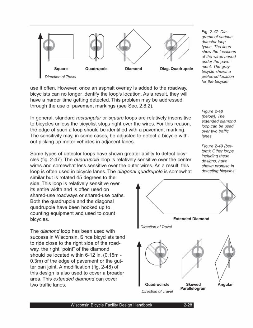
Some types of detector loops have shown greater ability to detect bicy-
cles (fig. 2-47). The quadrupole loop is relatively sensitive over the center
wires and somewhat less sensitive over the outer wires. As a result, this
loop is often used in bicycle lanes. The diagonal quadrupole is somewhat
similar but is rotated 45 degrees to the
side. This loop is relatively sensitive over
its entire width and is often used on
shared-use roadways or shared-use paths.
Both the quadrupole and the diagonal
quadrupole have been hooked up to
counting equipment and used to count
bicycles.
The diamond loop has been used with
success in Wisconsin. Since bicyclists tend
to ride close to the right side of the road-
way, the right “point” of the diamond
should be located within 6-12 in. (0.15m -
0.3m) of the edge of pavement or the gut-
ter pan joint. A modification (fig. 2-48) of
this design is also used to cover a broader
area. This extended diamond can cover
two traffic lanes.
Fig. 2-47: Dia-grams of variousdetector looptypes. The linesshow the locationsof the wires buriedunder the pave-ment. The graybicycle shows apreferred locationfor the bicycle.
Figure 2-48(below): Theextended diamondloop can be usedover two trafficlanes.
Figure 2-49 (bot-tom): Other loops,including thesedesigns, haveshown promise indetecting bicycles.
QuadrupoleSquare Diamond
Direction of Travel
Diag. Quadrupole
Quadrocircle SkewedParallelogram
Angular
Direction of Travel
Extended Diamond
Direction of Travel
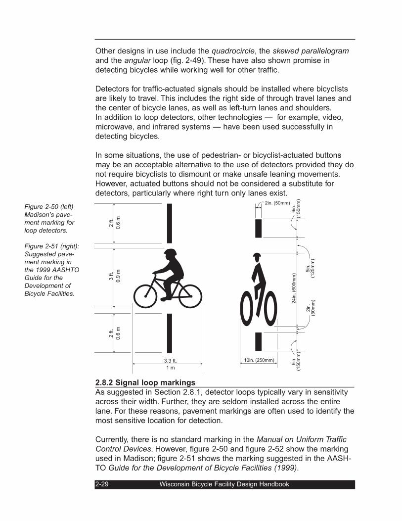
Other designs in use include the quadrocircle, the skewed parallelogramand the angular loop (fig. 2-49). These have also shown promise in
detecting bicycles while working well for other traffic.
Detectors for traffic-actuated signals should be installed where bicyclists
are likely to travel. This includes the right side of through travel lanes and
the center of bicycle lanes, as well as left-turn lanes and shoulders.
In addition to loop detectors, other technologies — for example, video,
microwave, and infrared systems — have been used successfully in
detecting bicycles.
In some situations, the use of pedestrian- or bicyclist-actuated buttons
may be an acceptable alternative to the use of detectors provided they do
not require bicyclists to dismount or make unsafe leaning movements.
However, actuated buttons should not be considered a substitute for
detectors, particularly where right turn only lanes exist.
2.8.2 Signal loop markings
As suggested in Section 2.8.1, detector loops typically vary in sensitivity
across their width. Further, they are seldom installed across the entire
lane. For these reasons, pavement markings are often used to identify the
most sensitive location for detection.
Currently, there is no standard marking in the Manual on Uniform TrafficControl Devices. However, figure 2-50 and figure 2-52 show the marking
used in Madison; figure 2-51 shows the marking suggested in the AASH-
TO Guide for the Development of Bicycle Facilities (1999).
2-29 Wisconsin Bicycle Facility Design Handbook
Figure 2-50 (left)Madison’s pave-ment marking forloop detectors.
Figure 2-51 (right):Suggested pave-ment marking inthe 1999 AASHTOGuide for theDevelopment ofBicycle Facilities.
10in. (250mm)
2in. (50mm)
6in
.(1
50
mm
)
5in
.(1
25
mm
)
24
in. (6
00
mm
)
2in
.(5
0m
m)
6in
.(1
50
mm
)
24"
36"
40"
24"
3 ft.
0.9
m
2 ft.
0.6
m
2 ft.
0.6
m
3.3 ft.
1 m
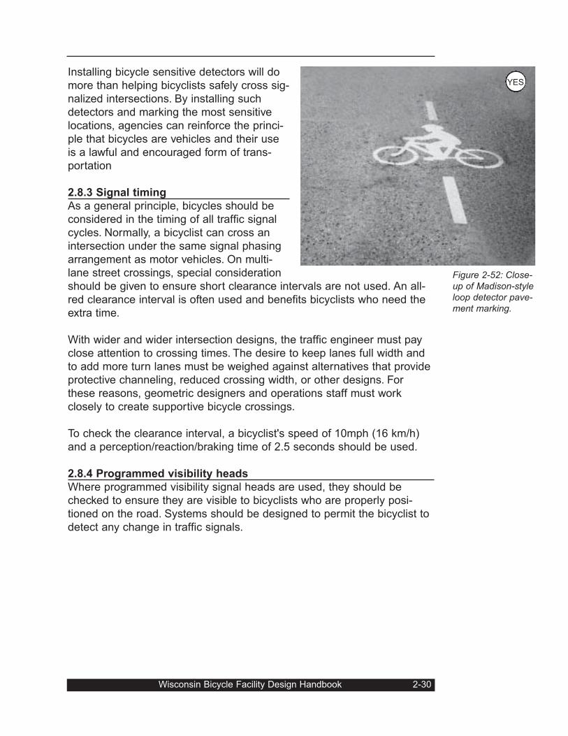
Installing bicycle sensitive detectors will do
more than helping bicyclists safely cross sig-
nalized intersections. By installing such
detectors and marking the most sensitive
locations, agencies can reinforce the princi-
ple that bicycles are vehicles and their use
is a lawful and encouraged form of trans-
portation
2.8.3 Signal timing
As a general principle, bicycles should be
considered in the timing of all traffic signal
cycles. Normally, a bicyclist can cross an
intersection under the same signal phasing
arrangement as motor vehicles. On multi-
lane street crossings, special consideration
should be given to ensure short clearance intervals are not used. An all-
red clearance interval is often used and benefits bicyclists who need the
extra time.
With wider and wider intersection designs, the traffic engineer must pay
close attention to crossing times. The desire to keep lanes full width and
to add more turn lanes must be weighed against alternatives that provide
protective channeling, reduced crossing width, or other designs. For
these reasons, geometric designers and operations staff must work
closely to create supportive bicycle crossings.
To check the clearance interval, a bicyclist's speed of 10mph (16 km/h)
and a perception/reaction/braking time of 2.5 seconds should be used.
2.8.4 Programmed visibility heads
Where programmed visibility signal heads are used, they should be
checked to ensure they are visible to bicyclists who are properly posi-
tioned on the road. Systems should be designed to permit the bicyclist to
detect any change in traffic signals.
Wisconsin Bicycle Facility Design Handbook 2-30
Figure 2-52: Close-up of Madison-styleloop detector pave-ment marking.
YES
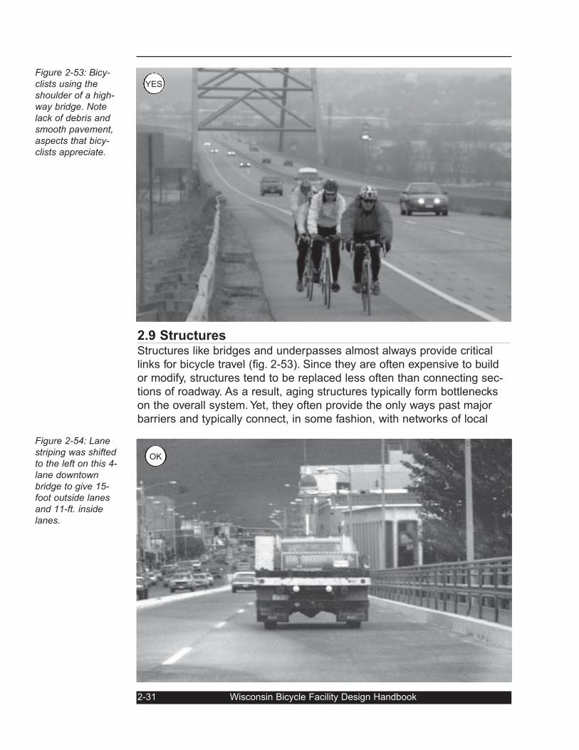
2.9 StructuresStructures like bridges and underpasses almost always provide critical
links for bicycle travel (fig. 2-53). Since they are often expensive to build
or modify, structures tend to be replaced less often than connecting sec-
tions of roadway. As a result, aging structures typically form bottlenecks
on the overall system. Yet, they often provide the only ways past major
barriers and typically connect, in some fashion, with networks of local
2-31 Wisconsin Bicycle Facility Design Handbook
Figure 2-53: Bicy-clists using theshoulder of a high-way bridge. Notelack of debris andsmooth pavement,aspects that bicy-clists appreciate.
Figure 2-54: Lanestriping was shiftedto the left on this 4-lane downtownbridge to give 15-foot outside lanesand 11-ft. insidelanes.
OK
YES
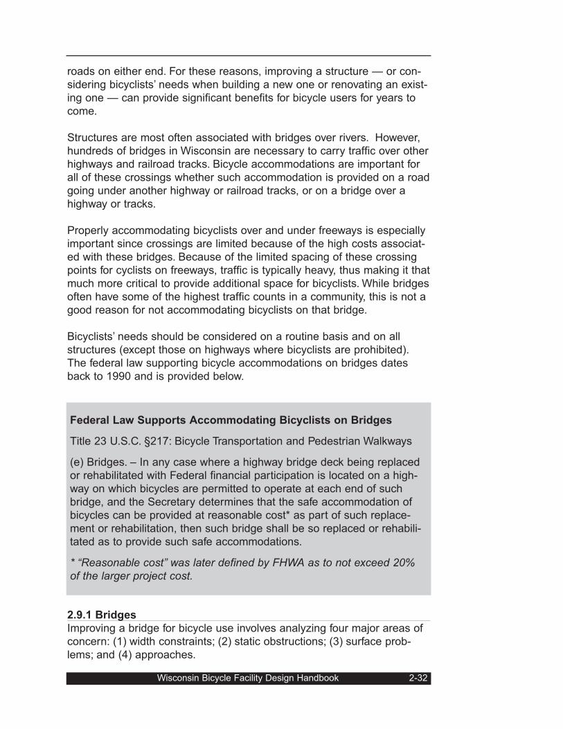
roads on either end. For these reasons, improving a structure — or con-
sidering bicyclists’ needs when building a new one or renovating an exist-
ing one — can provide significant benefits for bicycle users for years to
come.
Structures are most often associated with bridges over rivers. However,
hundreds of bridges in Wisconsin are necessary to carry traffic over other
highways and railroad tracks. Bicycle accommodations are important for
all of these crossings whether such accommodation is provided on a road
going under another highway or railroad tracks, or on a bridge over a
highway or tracks.
Properly accommodating bicyclists over and under freeways is especially
important since crossings are limited because of the high costs associat-
ed with these bridges. Because of the limited spacing of these crossing
points for cyclists on freeways, traffic is typically heavy, thus making it that
much more critical to provide additional space for bicyclists. While bridges
often have some of the highest traffic counts in a community, this is not a
good reason for not accommodating bicyclists on that bridge.
Bicyclists’ needs should be considered on a routine basis and on all
structures (except those on highways where bicyclists are prohibited).
The federal law supporting bicycle accommodations on bridges dates
back to 1990 and is provided below.
2.9.1 Bridges
Improving a bridge for bicycle use involves analyzing four major areas of
concern: (1) width constraints; (2) static obstructions; (3) surface prob-
lems; and (4) approaches.
Wisconsin Bicycle Facility Design Handbook 2-32
Federal Law Supports Accommodating Bicyclists on Bridges
Title 23 U.S.C. §217: Bicycle Transportation and Pedestrian Walkways
(e) Bridges. – In any case where a highway bridge deck being replaced
or rehabilitated with Federal financial participation is located on a high-
way on which bicycles are permitted to operate at each end of such
bridge, and the Secretary determines that the safe accommodation of
bicycles can be provided at reasonable cost* as part of such replace-
ment or rehabilitation, then such bridge shall be so replaced or rehabili-
tated as to provide such safe accommodations.
* “Reasonable cost” was later defined by FHWA as to not exceed 20%of the larger project cost.
Bridge deck width: Several options are available for accommodating bicy-
clists on bridges or on roads that cross under bridges. In urban and sub-
urban areas, a 5-ft striped area (unmarked or marked as bike lanes)
should be included in the basic design (fig. 2-55 and
2-56 top). At a minimum, a 4-ft striped area (not
marked as a bike lane) should be provided. Alterna-
tively, wide outside lanes can be provided as a mini-
mum form of accommodation as long as there is at
least 14 ft. of usable space in the outside lane (fig.
2-54 and fig. 2-56 bottom). Typically this translates to
at least 15.5 ft. from the curb face of a sidewalk on a
bridge. Sixteen feet is commonly used and should
be used whenever the outside lane is next to a para-
pet or concrete barrier (fig. 2-56 middle).
There is an exception to the above guidelines. On
low-speed urban bridges, generally with a projected
traffic of less than 2,000 ADT, it is often acceptable
to accommodate bicyclists in a standard travel lane.
In rural areas, speed and traffic volumes become
bigger factors. On rural roadways, shoulders should
be common features on all new bridges except low-
volume structures. See Figures 1 through 4 of FDM
11-15-1 for the appropriate widths. Generally for all
2-33 Wisconsin Bicycle Facility Design Handbook
Figure 2-55: A sub-urban bridge with5-ft shoulder forbicycles, as well asa sidewalk.
Figure 2-56: Rec-ommended widthsfor different struc-ture situations.
Travel LaneBike Laneor shoulder
5 ft. (1.5 m)
Wide Outside Lane
14 ft. (4.2 m) min.
Wide Outside Lane Next To
Parapet - 16 ft. (4.8 m)
YES
county and state highway bridges with ADTs in excess of 750, the mini-
mum width of shoulder areas is five feet. For state, county and town road
bridges with ADTs of less than 750, bicyclists will often be sharing the
travel lanes, but, since traffic is so low, bicyclists will seldom encounter
auto traffic on the bridge. Minimum offsets (shy distances) from bridge
parapets or sidewalks to the travel lanes on these bridges is either 2 or 3-
ft.. (See section 4-16-3 for a discussion of attached bicycle/pedestrian
paths on highway bridges).
Static obstructions: Bicycle-safe bridge railings
should be used on bridges specifically
designed to carry bicycle traffic, and on bridges
where specific protection of bicyclists is
deemed necessary. On highway bridges that
have full-width shoulders and are not marked
or signed as bikeways, the standard 32 in. (0.8
m) parapet/railing can be used.
On bridges that are signed or marked as bike-
ways and bicyclists are operating right next to
the railing (no sidewalk, for example), a 42 in.
(1 m) railing/parapet should be used as the
minimum height, while 54 in. (1.35 m) is the
preferred height. The higher railing/parapet
height is especially important and should be
used on long bridges, high bridges, and
bridges having high bicyclist volumes.
Lower railings (i.e., standard heights) may be
adequate for town road bridges which have low
bicycle and motor vehicle volumes or on those
bridges with sidewalks next to the railing.
In cases where existing railings are lower than desired, consideration
should be given to retrofitting an additional bicycle railing to the top,
bringing the total height to 42 or 54 inches. This is particularly useful on
relatively narrow bridges, where bicyclists may be riding closer to the rail-
ing than otherwise.
Guardrails on bridge approaches should be designed with the needs of
bicyclists in mind. As a general rule, a roadside barrier should be placed
as far from the traveled way as conditions permit.
Wisconsin Bicycle Facility Design Handbook 2-34
Figure 2-57: Thisbridge has a 54 in.railing that protectsbicyclists fromgoing over the topand into the river.Although a low-probability event,the consequenceswould be severe.
YES
Surface conditions: On all bridge decks, special care should be taken to
ensure that smooth bicycle-safe expansion joints are used. In cases
where joints are uneven, skid-resistant steel plates may be attached to
one side of the joint. Another option is to provide a rubberized joint filler
or cover.
The bridge deck itself should not pose a hazard
for bicyclists. Steel decking on draw bridges or
swing bridges can cause steering difficulties for
bicyclists. In general, such bridges should not
be designated as bicycle facilities without deter-
mining the deck’s effect on bicycle handling.
One option is to fill the voids in the steel deck
with lightweight concrete (Fig. 2-58); to save
money and weight, this treatment can be limit-
ed to the right sides near the edge of the road-
way. If this approach is used, it is advisable to
providing warning signs that direct bicyclists
toward the treated surface.
The accumulation of roadside debris may cause problems for bicyclists,
forcing them to ride farther out from the right edge than many would pre-
fer (fig. 2-59). Regular maintenance, particularly in the right half of the
outside lane and on any paved shoulders is important.
2-35 Wisconsin Bicycle Facility Design Handbook
Figure 2-58: Light-weight concretewas used to fill thevoids in this steelbridge deck.
Figure 2-59: Onthis bridge, debriscollects in the nar-row striped shoul-der; as a result ofthe surface condi-tions and theshoulder’s width,motorists mustchange lanes topass safely.
OK
NO
Bridge approaches: Bicycle provisions, whether bicycle lanes, paved
shoulders, or wide outside lanes, should be provided for the approaches
to bridges and, preferably, should continue 1000 ft (300 m) on either side
of major bridges to ensure a safe transition. If on- or off-ramps or inter-
sections are present, shoulders or wide outside lanes should continue at
least as far as the ramps or intersections.
On lower-speed bridges and ramps, a bicycle lane crossing is similar to
that used for turn lanes and a striping pattern should be used (see Sec.
3-7). If a wide outside lane is used, the extra width should be added to
the right-most through lane (fig. 2-60).
On high-speed bridges and ramps, shoulder striping should not cross
over the ramp, but should follow the ramp; another shoulder stripe should
pick up on the far side of the ramp. On high-speed bridges and ramps,
especially those with ramp AADTs over 800, it may be desirable for the
bicycle lane to leave via the off-ramp and, if necessary, re-enter via the
next available on-ramp.
2.9.2 Interchanges
Freeways present formidable barriers to bicycle circulation. Non-inter-
change crossings of freeways almost always provide a better level of
service and safety to bicyclists and pedestrians (fig. 2-61). Unfortunately,
because of the expense involved in bridging across freeways, few non-
interchange crossings are constructed in suburban and urban areas.
Wisconsin Bicycle Facility Design Handbook 2-36
Figure 2-60: At theend of a bridgewith wide outsidelanes, the extrawidth should con-tinue in the throughlane rather thanthe right turn lane.
YES
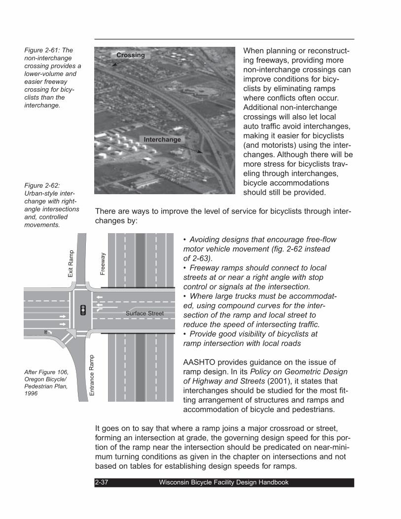
When planning or reconstruct-
ing freeways, providing more
non-interchange crossings can
improve conditions for bicy-
clists by eliminating ramps
where conflicts often occur.
Additional non-interchange
crossings will also let local
auto traffic avoid interchanges,
making it easier for bicyclists
(and motorists) using the inter-
changes. Although there will be
more stress for bicyclists trav-
eling through interchanges,
bicycle accommodations
should still be provided.
There are ways to improve the level of service for bicyclists through inter-
changes by:
• Avoiding designs that encourage free-flowmotor vehicle movement (fig. 2-62 insteadof 2-63).• Freeway ramps should connect to localstreets at or near a right angle with stopcontrol or signals at the intersection.• Where large trucks must be accommodat-ed, using compound curves for the inter-section of the ramp and local street toreduce the speed of intersecting traffic.• Provide good visibility of bicyclists atramp intersection with local roads
AASHTO provides guidance on the issue of
ramp design. In its Policy on Geometric Designof Highway and Streets (2001), it states that
interchanges should be studied for the most fit-
ting arrangement of structures and ramps and
accommodation of bicycle and pedestrians.
It goes on to say that where a ramp joins a major crossroad or street,
forming an intersection at grade, the governing design speed for this por-
tion of the ramp near the intersection should be predicated on near-mini-
mum turning conditions as given in the chapter on intersections and not
based on tables for establishing design speeds for ramps.
2-37 Wisconsin Bicycle Facility Design Handbook
ONLY
After Figure 106,Oregon Bicycle/Pedestrian Plan,1996
Exit R
am
p
Fre
ew
ay
Surface Street
Entr
ance R
am
p
Crossing
Interchange
Figure 2-61: Thenon-interchangecrossing provides alower-volume andeasier freewaycrossing for bicy-clists than theinterchange.
Figure 2-62:Urban-style inter-change with right-angle intersectionsand, controlledmovements.
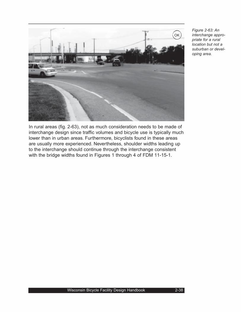
In rural areas (fig. 2-63), not as much consideration needs to be made of
interchange design since traffic volumes and bicycle use is typically much
lower than in urban areas. Furthermore, bicyclists found in these areas
are usually more experienced. Nevertheless, shoulder widths leading up
to the interchange should continue through the interchange consistent
with the bridge widths found in Figures 1 through 4 of FDM 11-15-1.
Wisconsin Bicycle Facility Design Handbook 2-38
Figure 2-63: Aninterchange appro-priate for a rurallocation but not asuburban or devel-oping area.
OK
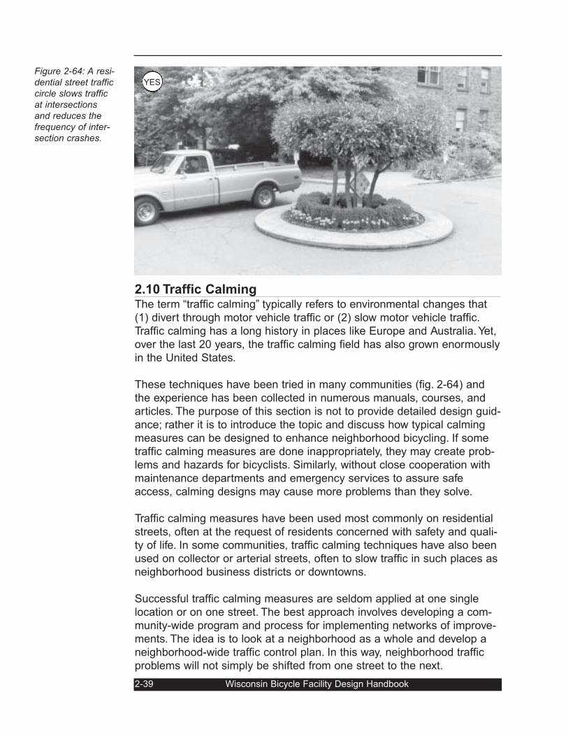
Figure 2-64: A resi-dential street trafficcircle slows trafficat intersectionsand reduces thefrequency of inter-section crashes.
2.10 Traffic CalmingThe term “traffic calming” typically refers to environmental changes that
(1) divert through motor vehicle traffic or (2) slow motor vehicle traffic.
Traffic calming has a long history in places like Europe and Australia. Yet,
over the last 20 years, the traffic calming field has also grown enormously
in the United States.
These techniques have been tried in many communities (fig. 2-64) and
the experience has been collected in numerous manuals, courses, and
articles. The purpose of this section is not to provide detailed design guid-
ance; rather it is to introduce the topic and discuss how typical calming
measures can be designed to enhance neighborhood bicycling. If some
traffic calming measures are done inappropriately, they may create prob-
lems and hazards for bicyclists. Similarly, without close cooperation with
maintenance departments and emergency services to assure safe
access, calming designs may cause more problems than they solve.
Traffic calming measures have been used most commonly on residential
streets, often at the request of residents concerned with safety and quali-
ty of life. In some communities, traffic calming techniques have also been
used on collector or arterial streets, often to slow traffic in such places as
neighborhood business districts or downtowns.
Successful traffic calming measures are seldom applied at one single
location or on one street. The best approach involves developing a com-
munity-wide program and process for implementing networks of improve-
ments. The idea is to look at a neighborhood as a whole and develop a
neighborhood-wide traffic control plan. In this way, neighborhood traffic
problems will not simply be shifted from one street to the next.
2-39 Wisconsin Bicycle Facility Design Handbook
YES
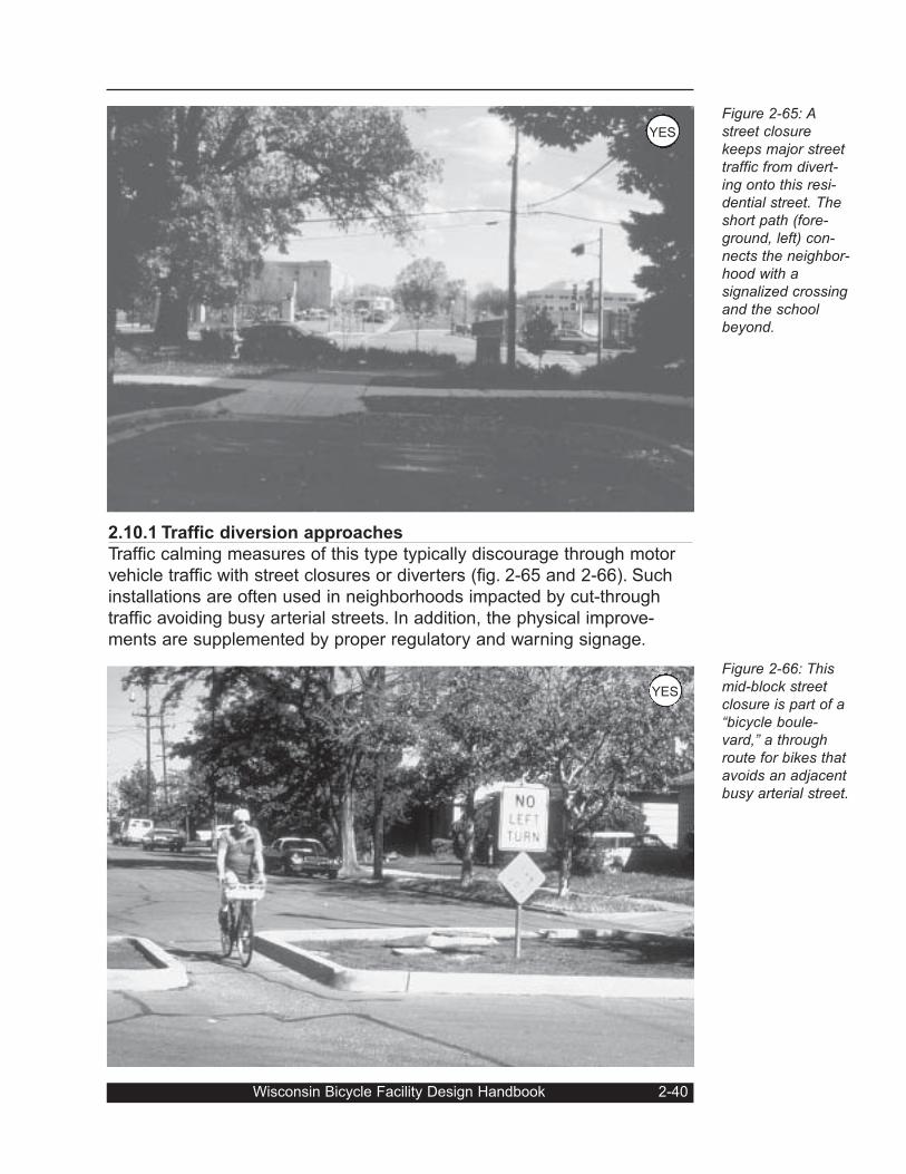
2.10.1 Traffic diversion approaches
Traffic calming measures of this type typically discourage through motor
vehicle traffic with street closures or diverters (fig. 2-65 and 2-66). Such
installations are often used in neighborhoods impacted by cut-through
traffic avoiding busy arterial streets. In addition, the physical improve-
ments are supplemented by proper regulatory and warning signage.
Wisconsin Bicycle Facility Design Handbook 2-40
Figure 2-65: Astreet closurekeeps major streettraffic from divert-ing onto this resi-dential street. Theshort path (fore-ground, left) con-nects the neighbor-hood with asignalized crossingand the schoolbeyond.
Figure 2-66: Thismid-block streetclosure is part of a“bicycle boule-vard,” a throughroute for bikes thatavoids an adjacentbusy arterial street.
YES
YES
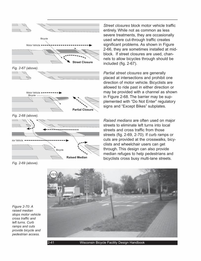
Street closures block motor vehicle traffic
entirely. While not as common as less
severe treatments, they are occasionally
used where cut-through traffic creates
significant problems. As shown in Figure
2-66, they are sometimes installed at mid-
block. If street closures are used, chan-
nels to allow bicycles through should be
included (fig. 2-67).
Partial street closures are generally
placed at intersections and prohibit one
direction of motor vehicle. Bicyclists are
allowed to ride past in either direction or
may be provided with a channel as shown
in Figure 2-68. The barrier may be sup-
plemented with “Do Not Enter” regulatory
signs and “Except Bikes” subplates.
Raised medians are often used on major
streets to eliminate left turns into local
streets and cross traffic from those
streets (fig. 2-69, 2-70). If curb ramps or
cuts are provided at the crosswalks, bicy-
clists and wheelchair users can get
through. This design can also provide
median refuges to help pedestrians and
bicyclists cross busy multi-lane streets.
2-41 Wisconsin Bicycle Facility Design Handbook
Fig. 2-67 (above).
Fig. 2-68 (above).
Fig. 2-69 (above).
Figure 2-70: Araised medianstops motor vehiclecross traffic andleft turns. Curbramps and cutsprovide bicycle andpedestrian access.
otor Vehicle
Bicycle
Raised Median
Bicycle
Motor Vehicle
Bicycle
Street Closure
Motor VehicleBicycle
Partial Closure
YES
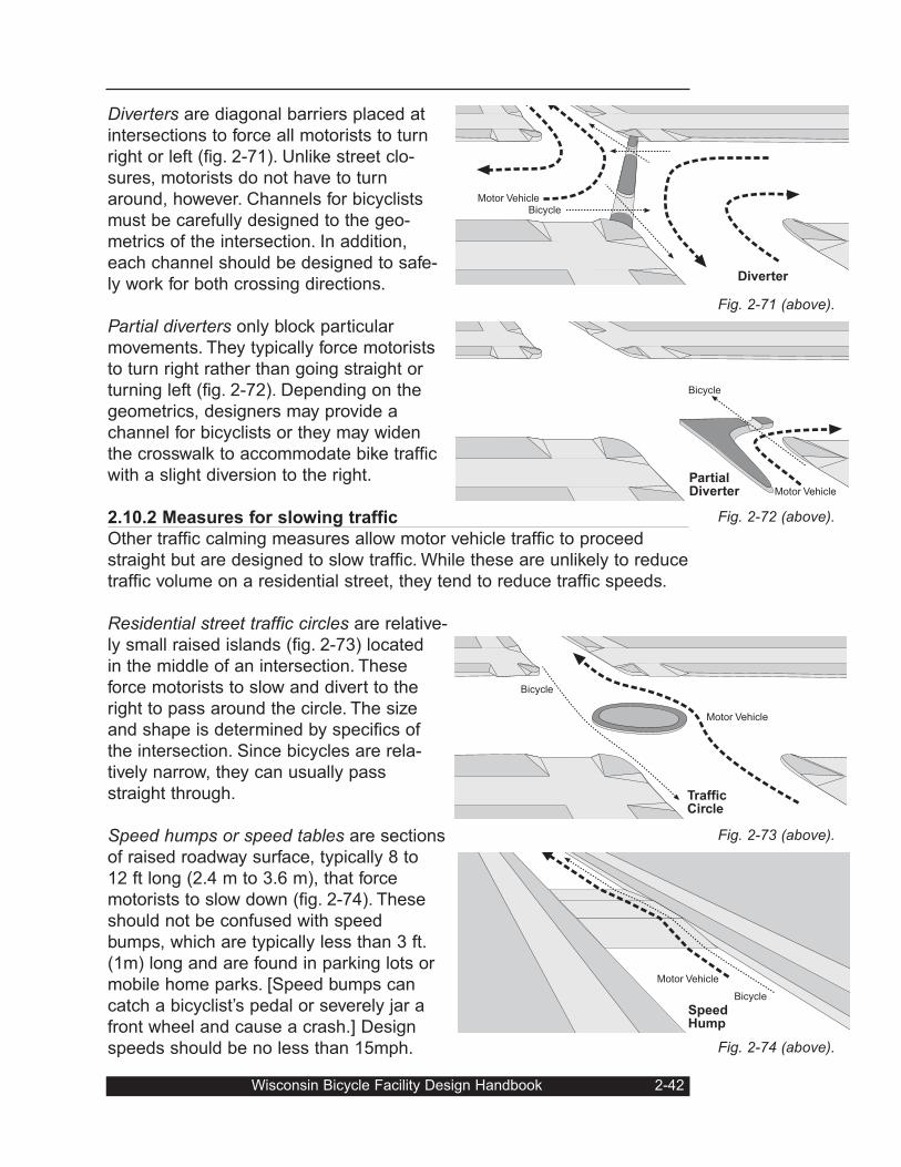
Diverters are diagonal barriers placed at
intersections to force all motorists to turn
right or left (fig. 2-71). Unlike street clo-
sures, motorists do not have to turn
around, however. Channels for bicyclists
must be carefully designed to the geo-
metrics of the intersection. In addition,
each channel should be designed to safe-
ly work for both crossing directions.
Partial diverters only block particular
movements. They typically force motorists
to turn right rather than going straight or
turning left (fig. 2-72). Depending on the
geometrics, designers may provide a
channel for bicyclists or they may widen
the crosswalk to accommodate bike traffic
with a slight diversion to the right.
2.10.2 Measures for slowing traffic
Other traffic calming measures allow motor vehicle traffic to proceed
straight but are designed to slow traffic. While these are unlikely to reduce
traffic volume on a residential street, they tend to reduce traffic speeds.
Residential street traffic circles are relative-
ly small raised islands (fig. 2-73) located
in the middle of an intersection. These
force motorists to slow and divert to the
right to pass around the circle. The size
and shape is determined by specifics of
the intersection. Since bicycles are rela-
tively narrow, they can usually pass
straight through.
Speed humps or speed tables are sections
of raised roadway surface, typically 8 to
12 ft long (2.4 m to 3.6 m), that force
motorists to slow down (fig. 2-74). These
should not be confused with speed
bumps, which are typically less than 3 ft.
(1m) long and are found in parking lots or
mobile home parks. [Speed bumps can
catch a bicyclist’s pedal or severely jar a
front wheel and cause a crash.] Design
speeds should be no less than 15mph.
Wisconsin Bicycle Facility Design Handbook 2-42
Fig. 2-71 (above).
Fig. 2-72 (above).
Fig. 2-73 (above).
Fig. 2-74 (above).
Motor VehicleBicycle
Diverter
Motor Vehicle
Bicycle
PartialDiverter
Motor Vehicle
Bicycle
TrafficCircle
SpeedHump
Motor Vehicle
Bicycle
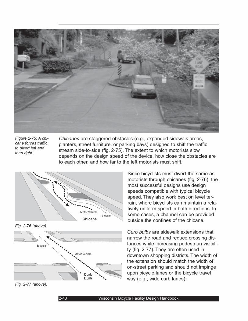
Chicanes are staggered obstacles (e.g., expanded sidewalk areas,
planters, street furniture, or parking bays) designed to shift the traffic
stream side-to-side (fig. 2-75). The extent to which motorists slow
depends on the design speed of the device, how close the obstacles are
to each other, and how far to the left motorists must shift.
Since bicyclists must divert the same as
motorists through chicanes (fig. 2-76), the
most successful designs use design
speeds compatible with typical bicycle
speed. They also work best on level ter-
rain, where bicyclists can maintain a rela-
tively uniform speed in both directions. In
some cases, a channel can be provided
outside the confines of the chicane.
Curb bulbs are sidewalk extensions that
narrow the road and reduce crossing dis-
tances while increasing pedestrian visibili-
ty (fig. 2-77). They are often used in
downtown shopping districts. The width of
the extension should match the width of
on-street parking and should not impinge
upon bicycle lanes or the bicycle travel
way (e.g., wide curb lanes).
2-43 Wisconsin Bicycle Facility Design Handbook
Figure 2-75: A chi-cane forces trafficto divert left andthen right.
Fig. 2-76 (above).
Fig. 2-77 (above).
Chicane
Motor Vehicle
Bicycle
Motor Vehicle
Bicycle
CurbBulb
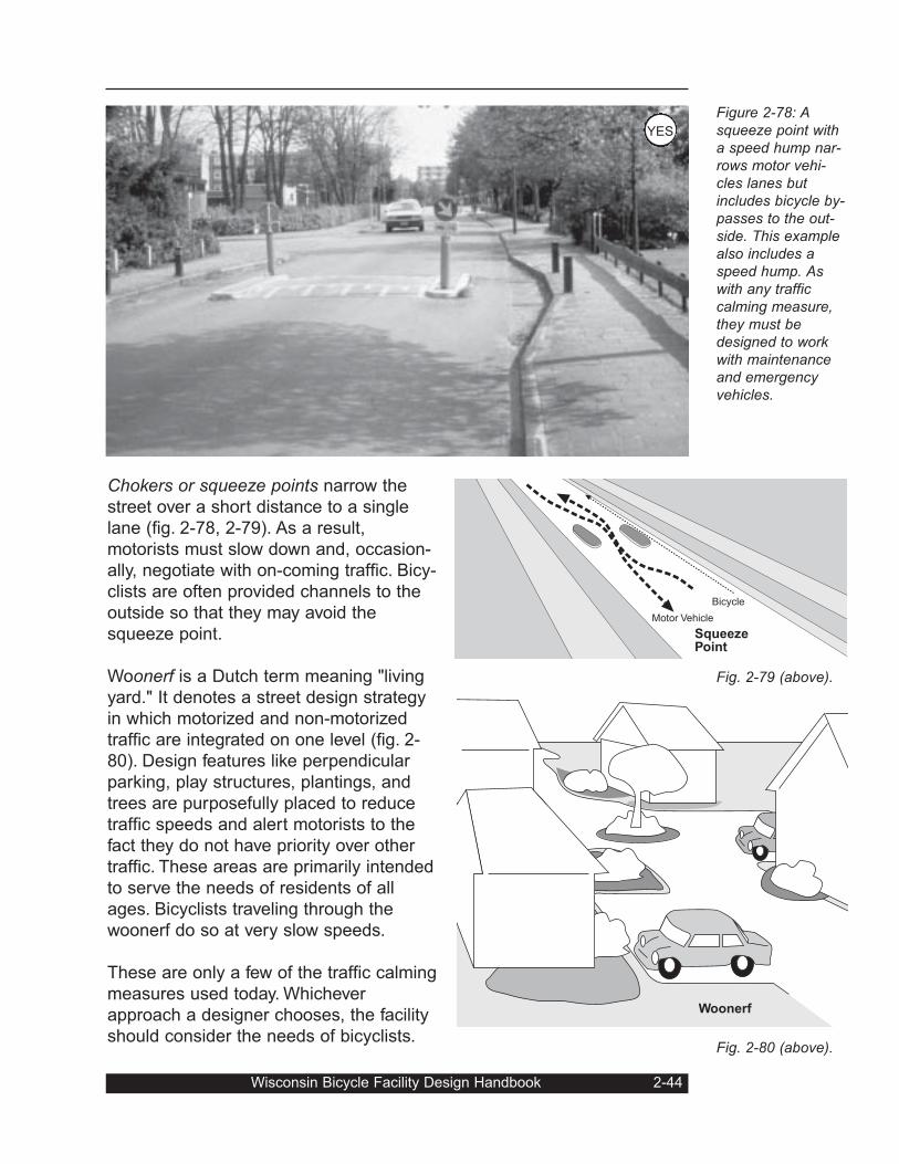
Wisconsin Bicycle Facility Design Handbook 2-44
Figure 2-78: Asqueeze point witha speed hump nar-rows motor vehi-cles lanes butincludes bicycle by-passes to the out-side. This examplealso includes aspeed hump. Aswith any trafficcalming measure,they must bedesigned to workwith maintenanceand emergencyvehicles.
Fig. 2-79 (above).
Fig. 2-80 (above).
Chokers or squeeze points narrow the
street over a short distance to a single
lane (fig. 2-78, 2-79). As a result,
motorists must slow down and, occasion-
ally, negotiate with on-coming traffic. Bicy-
clists are often provided channels to the
outside so that they may avoid the
squeeze point.
Woonerf is a Dutch term meaning "living
yard." It denotes a street design strategy
in which motorized and non-motorized
traffic are integrated on one level (fig. 2-
80). Design features like perpendicular
parking, play structures, plantings, and
trees are purposefully placed to reduce
traffic speeds and alert motorists to the
fact they do not have priority over other
traffic. These areas are primarily intended
to serve the needs of residents of all
ages. Bicyclists traveling through the
woonerf do so at very slow speeds.
These are only a few of the traffic calming
measures used today. Whichever
approach a designer chooses, the facility
should consider the needs of bicyclists.
SqueezePoint
Motor Vehicle
Bicycle
Woonerf
YES
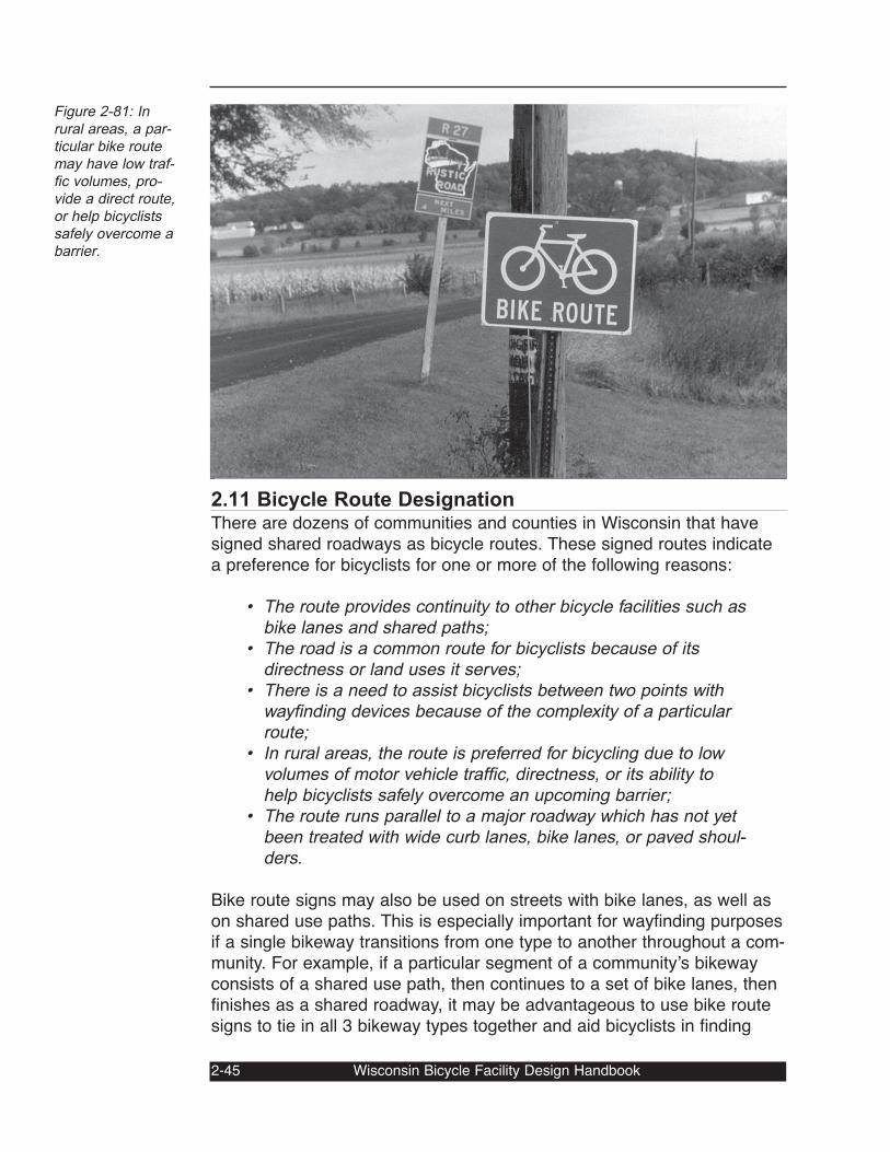
2.11 Bicycle Route DesignationThere are dozens of communities and counties in Wisconsin that havesigned shared roadways as bicycle routes. These signed routes indicatea preference for bicyclists for one or more of the following reasons:
• The route provides continuity to other bicycle facilities such asbike lanes and shared paths;
• The road is a common route for bicyclists because of itsdirectness or land uses it serves;
• There is a need to assist bicyclists between two points withwayfinding devices because of the complexity of a particularroute;
• In rural areas, the route is preferred for bicycling due to lowvolumes of motor vehicle traffic, directness, or its ability tohelp bicyclists safely overcome an upcoming barrier;
• The route runs parallel to a major roadway which has not yetbeen treated with wide curb lanes, bike lanes, or paved shoul-ders.
Bike route signs may also be used on streets with bike lanes, as well ason shared use paths. This is especially important for wayfinding purposesif a single bikeway transitions from one type to another throughout a com-munity. For example, if a particular segment of a communityʼs bikewayconsists of a shared use path, then continues to a set of bike lanes, thenfinishes as a shared roadway, it may be advantageous to use bike routesigns to tie in all 3 bikeway types together and aid bicyclists in finding
2-45 Wisconsin Bicycle Facility Design Handbook
Figure 2-81: Inrural areas, a par-ticular bike routemay have low traf-fic volumes, pro-vide a direct route,or help bicyclistssafely overcome abarrier.
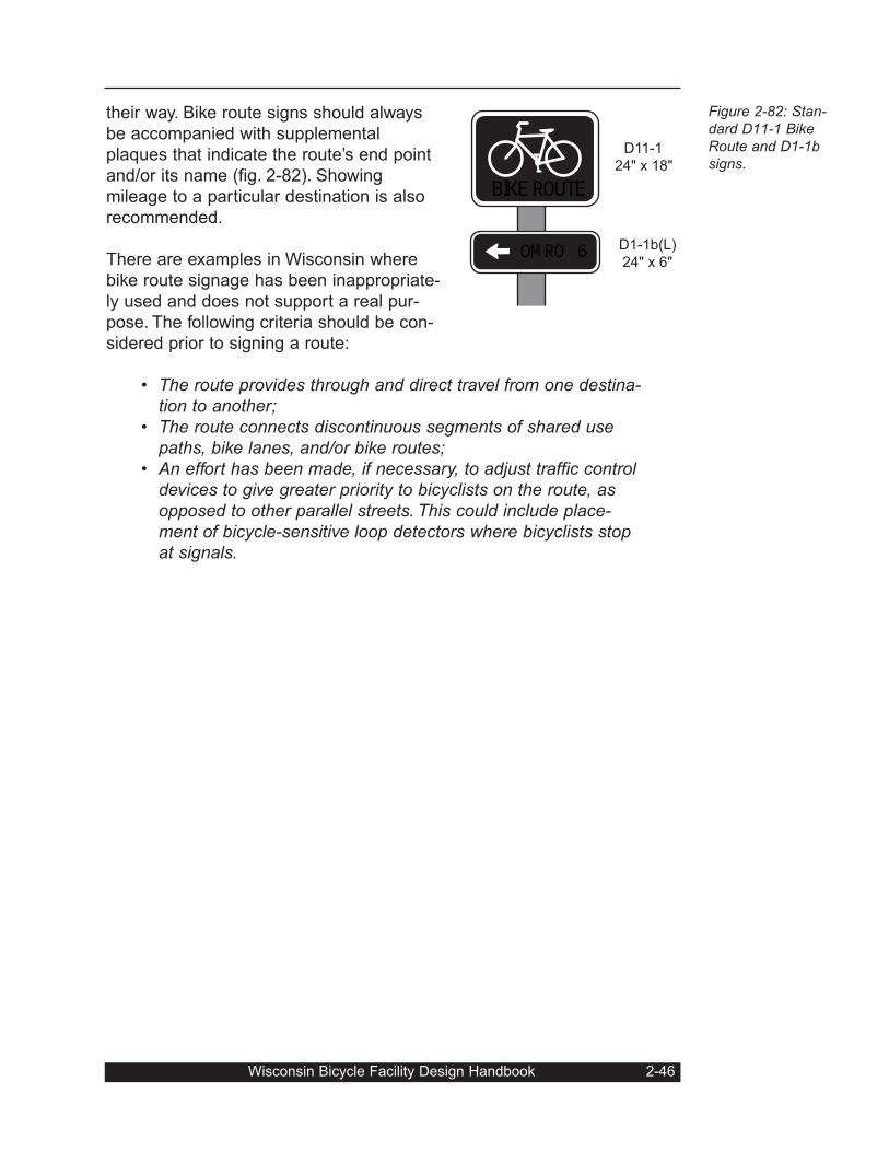
their way. Bike route signs should always
be accompanied with supplemental
plaques that indicate the route’s end point
and/or its name (fig. 2-82). Showing
mileage to a particular destination is also
recommended.
There are examples in Wisconsin where
bike route signage has been inappropriate-
ly used and does not support a real pur-
pose. The following criteria should be con-
sidered prior to signing a route:
• The route provides through and direct travel from one destina-tion to another;
• The route connects discontinuous segments of shared usepaths, bike lanes, and/or bike routes;
• An effort has been made, if necessary, to adjust traffic controldevices to give greater priority to bicyclists on the route, asopposed to other parallel streets. This could include place-ment of bicycle-sensitive loop detectors where bicyclists stopat signals.
Wisconsin Bicycle Facility Design Handbook 2-46
Figure 2-82: Stan-dard D11-1 BikeRoute and D1-1bsigns.BIKE ROUTE
D11-1
24" x 18"
SALEM 6 D1-1b(L)
24" x 6"OMRO
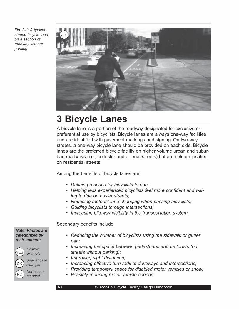
3 Bicycle LanesA bicycle lane is a portion of the roadway designated for exclusive or
preferential use by bicyclists. Bicycle lanes are always one-way facilities
and are identified with pavement markings and signing. On two-way
streets, a one-way bicycle lane should be provided on each side. Bicycle
lanes are the preferred bicycle facility on higher volume urban and subur-
ban roadways (i.e., collector and arterial streets) but are seldom justified
on residential streets.
Among the benefits of bicycle lanes are:
• Defining a space for bicyclists to ride;• Helping less experienced bicyclists feel more confident and will-
ing to ride on busier streets;• Reducing motorist lane changing when passing bicyclists;• Guiding bicyclists through intersections;• Increasing bikeway visibility in the transportation system.
Secondary benefits include:
• Reducing the number of bicyclists using the sidewalk or gutterpan;
• Increasing the space between pedestrians and motorists (onstreets without parking);
• Improving sight distances;• Increasing effective turn radii at driveways and intersections;• Providing temporary space for disabled motor vehicles or snow;• Possibly reducing motor vehicle speeds.
3-1 Wisconsin Bicycle Facility Design Handbook
Fig. 3-1: A typicalstriped bicycle laneon a section ofroadway withoutparking.
Note: Photos are
categorized by
their content:
Positiveexample
Special caseexample
Not recom-mended.
OK
NO
YES
YES
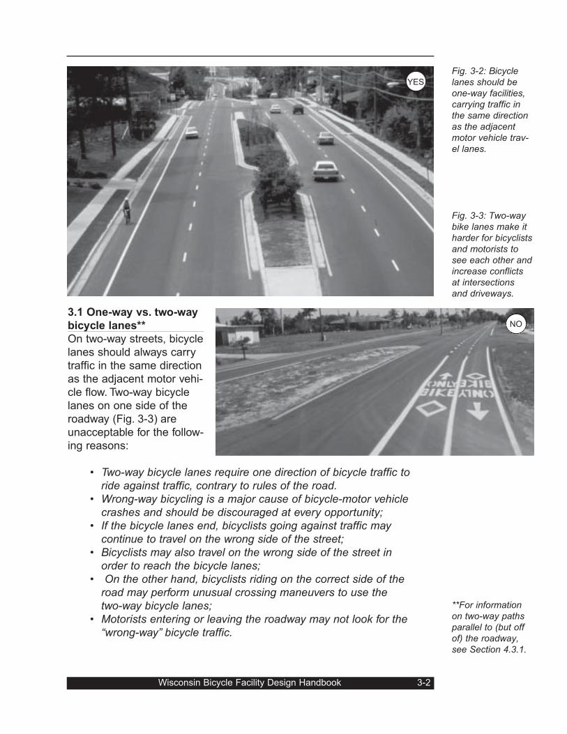
3.1 One-way vs. two-way
bicycle lanes**
On two-way streets, bicycle
lanes should always carry
traffic in the same direction
as the adjacent motor vehi-
cle flow. Two-way bicycle
lanes on one side of the
roadway (Fig. 3-3) are
unacceptable for the follow-
ing reasons:
• Two-way bicycle lanes require one direction of bicycle traffic toride against traffic, contrary to rules of the road.
• Wrong-way bicycling is a major cause of bicycle-motor vehiclecrashes and should be discouraged at every opportunity;
• If the bicycle lanes end, bicyclists going against traffic maycontinue to travel on the wrong side of the street;
• Bicyclists may also travel on the wrong side of the street inorder to reach the bicycle lanes;
• On the other hand, bicyclists riding on the correct side of theroad may perform unusual crossing maneuvers to use thetwo-way bicycle lanes;
• Motorists entering or leaving the roadway may not look for the“wrong-way” bicycle traffic.
Wisconsin Bicycle Facility Design Handbook 3-2
Fig. 3-2: Bicyclelanes should beone-way facilities,carrying traffic inthe same directionas the adjacentmotor vehicle trav-el lanes.
Fig. 3-3: Two-waybike lanes make itharder for bicyclistsand motorists tosee each other andincrease conflictsat intersectionsand driveways.
**For informationon two-way pathsparallel to (but offof) the roadway,see Section 4.3.1.
NO
YES
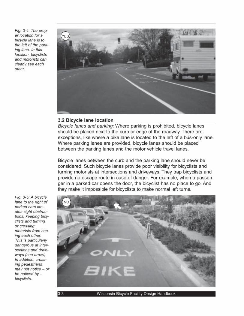
3.2 Bicycle lane location
Bicycle lanes and parking: Where parking is prohibited, bicycle lanes
should be placed next to the curb or edge of the roadway. There are
exceptions, like where a bike lane is located to the left of a bus-only lane.
Where parking lanes are provided, bicycle lanes should be placed
between the parking lanes and the motor vehicle travel lanes.
Bicycle lanes between the curb and the parking lane should never be
considered. Such bicycle lanes provide poor visibility for bicyclists and
turning motorists at intersections and driveways. They trap bicyclists and
provide no escape route in case of danger. For example, when a passen-
ger in a parked car opens the door, the bicyclist has no place to go. And
they make it impossible for bicyclists to make normal left turns.
3-3 Wisconsin Bicycle Facility Design Handbook
Fig. 3-4: The prop-er location for abicycle lane is tothe left of the park-ing lane. In thislocation, bicyclistsand motorists canclearly see eachother.
Fig. 3-5: A bicyclelane to the right ofparked cars cre-ates sight obstruc-tions, keeping bicy-clists and turningor crossingmotorists from see-ing each other.This is particularlydangerous at inter-sections and drive-ways (see arrow).In addition, cross-ing pedestriansmay not notice – orbe noticed by –bicyclists.
➜NO
YES
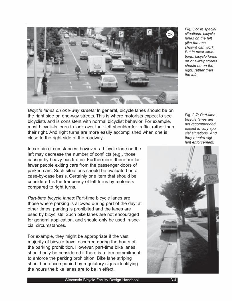
Bicycle lanes on one-way streets: In general, bicycle lanes should be on
the right side on one-way streets. This is where motorists expect to see
bicyclists and is consistent with normal bicyclist behavior. For example,
most bicyclists learn to look over their left shoulder for traffic, rather than
their right. And right turns are more easily accomplished when one is
close to the right side of the roadway.
In certain circumstances, however, a bicycle lane on the
left may decrease the number of conflicts (e.g., those
caused by heavy bus traffic). Furthermore, there are far
fewer people exiting cars from the passenger doors of
parked cars. Such situations should be evaluated on a
case-by-case basis. Certainly one item that should be
considered is the frequency of left turns by motorists
compared to right turns.
Part-time bicycle lanes: Part-time bicycle lanes are
those where parking is allowed during part of the day; at
other times, parking is prohibited and the lanes are
used by bicyclists. Such bike lanes are not encouraged
for general application, and should only be used in spe-
cial circumstances.
For example, they might be appropriate if the vast
majority of bicycle travel occurred during the hours of
the parking prohibition. However, part-time bike lanes
should only be considered if there is a firm commitment
to enforce the parking prohibition. Bike lane striping
should be accompanied by regulatory signs identifying
the hours the bike lanes are to be in effect.
Wisconsin Bicycle Facility Design Handbook 3-4
Fig. 3-6: In specialsituations, bicyclelanes on the left(like the oneshown) can work.But in most situa-tions, bicycle laneson one-way streetsshould be on theright, rather thanthe left.
Fig. 3-7: Part-timebicycle lanes arenot recommendedexcept in very spe-cial situations. Andthey require vigi-lant enforcement.
OK

Contraflow bicycle lanes: Contra-flow bicycle lanes accommodate bike
traffic moving in the opposite direction from the rest of traffic. They are
generally not recommended, and are not appropriate on a two-way street.
However, on some one-way streets they may be suitable where:
• They provide a substantial reduction in out-of-direction travel;• Currently, there is significant wrong-way riding as a result of
the added trip lengths;• They provide direct access to high-use destinations;• There are few intersecting streets, alleys, or driveways on the
side of the contra-flow lane;• Bicyclists can safely and conveniently enter and leave the
contra-flow lane.
Contra-flow bicycle lanes are sometimes found on arterial roadways (fig.
3-8). In addition, a contra-flow lane may also be appropriate on local
access or residential streets that have been made one-way to calm traffic
or otherwise restrict motor vehicle access.
3-5 Wisconsin Bicycle Facility Design Handbook
Fig. 3-8: A contra-flow bicycle laneon a one-waystreet protected bya barrier becauseof high volumes ofopposite-flowmotor vehicle traf-fic. On the far sideof the street, thereis another bikelane for bicyclistsgoing the samedirection as traffic.
Peak hour wide lane: an alternative to part-time bicycle lanes
Providing a peak hour parking prohibition in wide outside lanes, ratherthan designating part-time bicycle lanes, may be preferable in manycases. During the peak hour, bicyclists and motorists share the extrawidth in the default wide lane. During off-peak hours, a default bike laneexists to the left of the parking.
OK
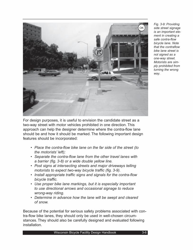
For design purposes, it is useful to envision the candidate street as a
two-way street with motor vehicles prohibited in one direction. This
approach can help the designer determine where the contra-flow lane
should be and how it should be marked. The following important design
features should be incorporated:
• Place the contra-flow bike lane on the far side of the street (tothe motorists’ left);
• Separate the contra-flow lane from the other travel lanes witha barrier (fig. 3-8) or a wide double yellow line.
• Post signs at intersecting streets and major driveways tellingmotorists to expect two-way bicycle traffic (fig. 3-9).
• Install appropriate traffic signs and signals for the contra-flowbicycle traffic.
• Use proper bike lane markings, but it is especially importantto use directional arrows and occasional signage to reducewrong-way riding.
• Determine in advance how the lane will be swept and clearedof snow.
Because of the potential for serious safety problems associated with con-
tra-flow bike lanes, they should only be used in well-chosen circum-
stances. They should also be carefully designed and evaluated following
installation.
Wisconsin Bicycle Facility Design Handbook 3-6
Fig. 3-9: Providingside street signageis an important ele-ment in creating asafe contra-flowbicycle lane. Notethat the contraflowbike lane street isnot signed as aone-way street.Motorists are sim-ply prohibited fromturning the wrongway.
OK
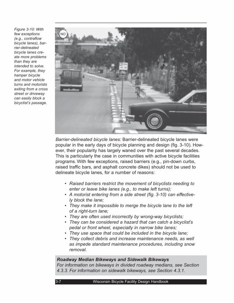
Barrier-delineated bicycle lanes: Barrier-delineated bicycle lanes were
popular in the early days of bicycle planning and design (fig. 3-10). How-
ever, their popularity has largely waned over the past several decades.
This is particularly the case in communities with active bicycle facilities
programs. With few exceptions, raised barriers (e.g., pin-down curbs,
raised traffic bars, and asphalt concrete dikes) should not be used to
delineate bicycle lanes, for a number of reasons:
• Raised barriers restrict the movement of bicyclists needing toenter or leave bike lanes (e.g., to make left turns);
• A motorist entering from a side street (fig. 3-10) can effective-ly block the lane;
• They make it impossible to merge the bicycle lane to the leftof a right-turn lane;
• They are often used incorrectly by wrong-way bicyclists;• They can be considered a hazard that can catch a bicyclist’s
pedal or front wheel, especially in narrow bike lanes;• They use space that could be included in the bicycle lane;• They collect debris and increase maintenance needs, as well
as impede standard maintenance procedures, including snowremoval.
3-7 Wisconsin Bicycle Facility Design Handbook
Figure 3-10: Withfew exceptions(e.g., contraflowbicycle lanes), bar-rier-delineatedbicycle lanes cre-ate more problemsthan they areintended to solve.For example, theyhamper bicycleand motor vehicleturns and motoristsexiting from a crossstreet or drivewaycan easily block abicyclist’s passage.
Roadway Median Bikeways and Sidewalk Bikeways
For information on bikeways in divided roadway medians, see Section4.3.3. For information on sidewalk bikeways, see Section 4.3.1.
NO
Wisconsin Bicycle Facility Design Handbook 3-8
Fig. 3-11: Seriouspavement cracks ina bicycle lane cancause a bicyclist’sfront wheel to turn,resulting in a crash.
3.3 Bicycle lane surface quality
Bicycle lanes should be paved to the same standards as
adjacent traffic lanes. The surface should be smooth and free
of potholes and the pavement edge should be uniform,
whether it meets a shoulder or a gutter pan. There should be
no ridges or gaps that could catch a bicycle wheel.
Concrete and asphalt; In concrete construction, there should
be no longitudinal joints in the bike lane or at the lane stripe,
where they can be hidden by the paint. Joints should be saw-
cut. This is especially important if a joint is placed between a
bike lane and travel lane. The painted lane line should be
placed on either side of the joint, ensuring the bike lane has
a 5-ft (1.5m). width, measured from the curb face. With asphalt construc-
tion, the paved surface should continue smoothly to where it meets gutter
pan level; pavement overlays should not be stopped at the bike lane
stripe.
Grates and utilities: In addition, manholes, drainage grates, and utility
covers should be located outside the bicycle lane because of the difficulty
maintaining adequate tolerances. Grates should be contained fully within
the standard 2-ft. (0.3m) gutter pan.
Maintenance: Cracks, potholes, and other imperfections should be
repaired to an acceptable standard as part of routine maintenance proce-
dures. Hazards for bicyclists are especially pronounced for cracks and-
faults that run in bicyclists’ direction of travel. In addition, since bicycle
lanes are not “swept” by the passing motor vehicles, they tend to collect
debris. For this reason, sweepers should pay extra attention to the bike
lane to keep it clear. Depending on the season, the particular roadway,
and its surrounding environment, sweeping schedules may need to be
adjusted to hit a particular bike lane more often than otherwise called for.
At the same time, proper construction can eliminate some of these prob-
lems from the start. For example, paving into unpaved driveways and
cross streets can reduce the amount of debris brought up onto the bike
lane by cross traffic.
In some communities, bicyclists ride through the winter. In other commu-
nities, they might like to if the bike lanes were clear. While experienced
commuters may use special “studded” tires and often must “take” the trav-
el lane, many bicyclists are reluctant to do so. It is understandable that
during a storm, snow may be plowed into the bicycle lane. However, the
bicycle lane should not be used for long-term snow storage. The snow
should be removed quickly.
Note: For moreon maintenanceissues, seeAppendix A.
NO
3.4 Bicycle lane width
Curbed asphalt street, noparking: On a curbed asphalt
street without parking, the
standard clear width of a bicy-
cle lane is 4 ft. (1.2 m), as
measured from the inside of
the stripe to the joint line with
the gutter pan (fig. 3-12).
Depending on whether a 1 ft.
or 2 ft. (0.6 m) gutter pan is
used, the total width from face
of curb to the inside of the
bicycle lane stripe would be
either 5 or 6 ft. ( 1.5 - 1.8 m).
On an asphalt roadway, the width of the gutter pan is not included within
the bicycle lane measurement because the gutter pan is not considered
usable space. There are at least six reasons for this:
• Riding in the gutter increases the likelihood that a bicyclist willhit a pedal on the curb;
• Joint lines between the roadway and gutter pan are oftenuneven and can cause a bicyclist to crash;
• Debris tends to collect in the gutter, having been swept thereby passing motor vehicles;
• Drainage grates are most often located in the gutter pan;• The gutter pan may have a greater cross slope than the rest
of the roadway; this may cause problems for adult tricycles;• A bicyclist riding close to the curb is less likely to be seen by
motorists at cross streets and would have a more difficult timetaking evasive action.
Where space is tight but drainagerequirements dictate an 18 in. (0.45 m)drain, a special 1 ft. (0.3 m) curbheadmay be used with a 1 ft. (0.3 m) gutterpan (fig. 3-13).
At drain locations, the width of the curbhead is reduced to 6 in. (0.15 m) tomake room for the grate.
3-9 Wisconsin Bicycle Facility Design Handbook
4 ft (1.2m)
Bicycle Lane
Gutter Pan
1 ft (0.3m)
Min. 5 ft (1.5m)
Total Width
Bike lane with1 ft. (0.3 m)gutter pan
th
Str
ipe
Figure 3-12: Abicycle lane next tothe curb on anasphalt roadwaymay be 4ft. wide.However, thisshould not includethe gutter pan.
Figure 3-13: Adrain inset into a1ft. curb head pro-vides extra spacein tight places.
YES
Curbed concrete street, no parking: On a con-
crete roadway with integral gutter and travel
lane (Fig. 3-14), the distance from face of curb
to the inside of the bicycle lane stripe should
be a minimum of 5 ft. (1.5 m). While there is
no joint line between the roadway and the gut-
ter, bicyclists will still need a “shy distance” to
the curb face, for safety reasons.
Wider bicycle lane situations: Wider bicycle
lanes may be desirable in high use areas, on
high-speed facilities where wider shoulders
are warranted, or where they are shared with
pedestrians. Additional width is also desirable when the adjacent traffic
lane is less than 11 ft. wide. In such conditions, motorists may drive closer
to the bicycle lane and a wider bicycle lane can help keep the separation.
Adequate marking or signing should be used so that the bike lanes are
not mistaken for motor vehicle travel lanes or parking areas.
Curbed street with parking: As mentioned previously, on a curbed street
with parking, the bicycle lane should be on the roadway side of the park-
ing (Fig. 3-15). The standard width of a bicycle lane in such conditions is
5 ft. (1.5 m). This width allows a bicyclist to stay to the left in case some-
one in a parked car opens the door (Fig. 3-17). If parking volume is sub-
stantial or turnover high, 1 to 2 ft. (0.3 - 0.6 m) of additional width is desir-
able. An equally important dimension is the width of the parking lane —
typically 8 to 10 ft. (2.4 m - 3 m).
Wisconsin Bicycle Facility Design Handbook 3-10
Min. 5 ft (1.5m)
1 ft (0.3m)
Bicycle laneon concreteroadway withintegral curband gutter
Str
ipe
Figure 3-14: On aconcrete roadwaywith integral gutterand travel lane,there is no gutterpan joint line. If ajoint needs to beplaced, it is best tolocate it 1 ft. (0.3m)from the curb face.
Figure 3-15: Unlikebicycles, motorvehicles are notaffected by thejoint between theroadway and thegutter pan. As aresult, the gutterpan is includedwhen determiningthe width of theparking lane.
YES
It may be tempting to narrow the parking lane
to create more space for the bicycle lane.
However, this approach can produce unin-
tended results. Striping a narrow parking lane
does not reduce the width of parked motor
vehicles (Fig. 3-17). And they may take up
part of the bike lane in the process. Narrow-
ing the parking lane too much will put the
bicyclist closer to the side of the parked car,
leaving less clearance to get around an open-
ing door.
Overall, the total width of the bicycle and
parking lanes should be a minimum of 13 ft.
(3.9 m). In exceptional circumstances, a mini-
mum combined width of 12 ft. (3.6 m) may be
justified. However, it is not recommended.
Combining bicycle lanes and parking lanes
without painting parking “T”s or striping
between the two is found in some communi-
ties. However, the undesignated space may
look like a motor vehicle lane. As a result, it
may be preferable to identify the parking lane.
Figure 3-16: Typi-cal dimensions fora bicycle lane nextto a parking lane.
Fig. 3-17: An other-wise adequatebicycle lane next toa very narrowparking lane.
3-11 Wisconsin Bicycle Facility Design Handbook
Pa
rkin
g “
T”
or
str
ipe
Parking Lane
8 - 10 ft (2.4 - 3m) typ.
Bicycle lanenext to parking
Str
ipe
Bicycle Lane
5 ft (1.5m) min.
gp
NO
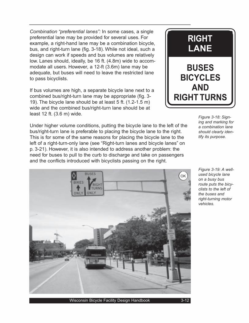
Combination “preferential lanes”: In some cases, a single
preferential lane may be provided for several uses. For
example, a right-hand lane may be a combination bicycle,
bus, and right-turn lane (fig. 3-18). While not ideal, such a
design can work if speeds and bus volumes are relatively
low. Lanes should, ideally, be 16 ft. (4.8m) wide to accom-
modate all users. However, a 12-ft (3.6m) lane may be
adequate, but buses will need to leave the restricted lane
to pass bicyclists.
If bus volumes are high, a separate bicycle lane next to a
combined bus/right-turn lane may be appropriate (fig. 3-
19). The bicycle lane should be at least 5 ft. (1.2-1.5 m)
wide and the combined bus/right-turn lane should be at
least 12 ft. (3.6 m) wide.
Under higher volume conditions, putting the bicycle lane to the left of the
bus/right-turn lane is preferable to placing the bicycle lane to the right.
This is for some of the same reasons for placing the bicycle lane to the
left of a right-turn-only lane (see “Right-turn lanes and bicycle lanes” on
p. 3-21). However, it is also intended to address another problem: the
need for buses to pull to the curb to discharge and take on passengers
and the conflicts introduced with bicyclists passing on the right.
Wisconsin Bicycle Facility Design Handbook 3-12
Figure 3-18: Sign-ing and marking fora combination laneshould clearly iden-tify its purpose.
Figure 3-19: A well-used bicycle laneon a busy busroute puts the bicy-clists to the left ofthe buses andright-turning motorvehicles.
RIGHTLANE
BUSESBICYCLES
ANDRIGHT TURNS
OK
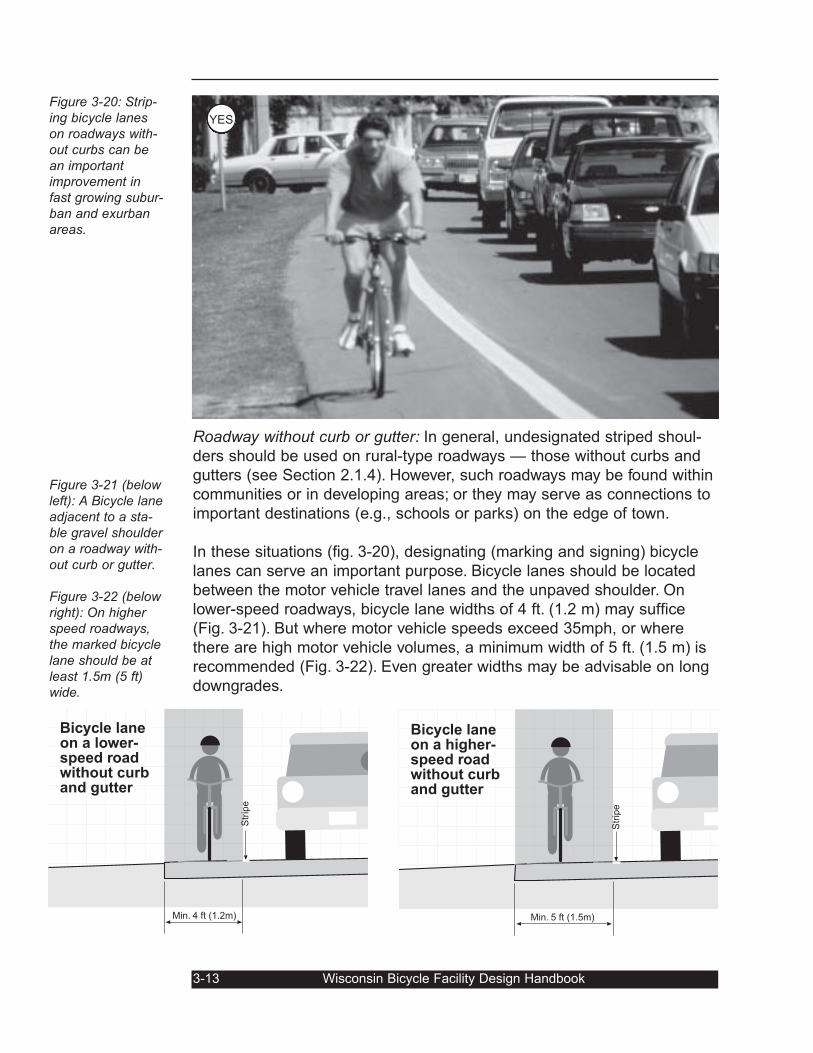
Figure 3-20: Strip-ing bicycle laneson roadways with-out curbs can bean importantimprovement infast growing subur-ban and exurbanareas.
Figure 3-21 (belowleft): A Bicycle laneadjacent to a sta-ble gravel shoulderon a roadway with-out curb or gutter.
Figure 3-22 (belowright): On higherspeed roadways,the marked bicyclelane should be atleast 1.5m (5 ft)wide.
Roadway without curb or gutter: In general, undesignated striped shoul-
ders should be used on rural-type roadways — those without curbs and
gutters (see Section 2.1.4). However, such roadways may be found within
communities or in developing areas; or they may serve as connections to
important destinations (e.g., schools or parks) on the edge of town.
In these situations (fig. 3-20), designating (marking and signing) bicycle
lanes can serve an important purpose. Bicycle lanes should be located
between the motor vehicle travel lanes and the unpaved shoulder. On
lower-speed roadways, bicycle lane widths of 4 ft. (1.2 m) may suffice
(Fig. 3-21). But where motor vehicle speeds exceed 35mph, or where
there are high motor vehicle volumes, a minimum width of 5 ft. (1.5 m) is
recommended (Fig. 3-22). Even greater widths may be advisable on long
downgrades.
3-13 Wisconsin Bicycle Facility Design Handbook
Min. 4 ft (1.2m)
Bicycle laneon a lower-speed roadwithout curband gutter
Str
ipe
Min. 5 ft (1.5m)
Bicycle laneon a higher-speed roadwithout curband gutter
Str
ipe
YES
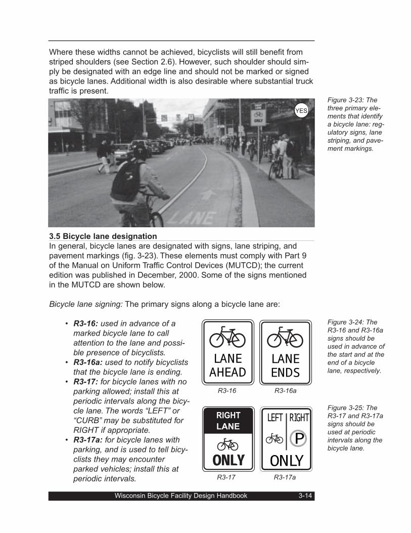
Where these widths cannot be achieved, bicyclists will still benefit from
striped shoulders (see Section 2.6). However, such shoulder should sim-
ply be designated with an edge line and should not be marked or signed
as bicycle lanes. Additional width is also desirable where substantial truck
traffic is present.
3.5 Bicycle lane designation
In general, bicycle lanes are designated with signs, lane striping, and
pavement markings (fig. 3-23). These elements must comply with Part 9
of the Manual on Uniform Traffic Control Devices (MUTCD); the current
edition was published in December, 2000. Some of the signs mentioned
in the MUTCD are shown below.
Bicycle lane signing: The primary signs along a bicycle lane are:
• R3-16: used in advance of amarked bicycle lane to callattention to the lane and possi-ble presence of bicyclists.
• R3-16a: used to notify bicycliststhat the bicycle lane is ending.
• R3-17: for bicycle lanes with noparking allowed; install this atperiodic intervals along the bicy-cle lane. The words “LEFT” or“CURB” may be substituted forRIGHT if appropriate.
• R3-17a: for bicycle lanes withparking, and is used to tell bicy-clists they may encounterparked vehicles; install this atperiodic intervals.
Wisconsin Bicycle Facility Design Handbook 3-14
Figure 3-23: Thethree primary ele-ments that identifya bicycle lane: reg-ulatory signs, lanestriping, and pave-ment markings.
Figure 3-24: TheR3-16 and R3-16asigns should beused in advance ofthe start and at theend of a bicyclelane, respectively.
Figure 3-25: TheR3-17 and R3-17asigns should beused at periodicintervals along thebicycle lane.
LANEENDSLANEAHEADR3-16 R3-16a
OONNLLYYRIGHT
LANE PLEFT RIGHT
ONLYR3-17 R3-17a
YES
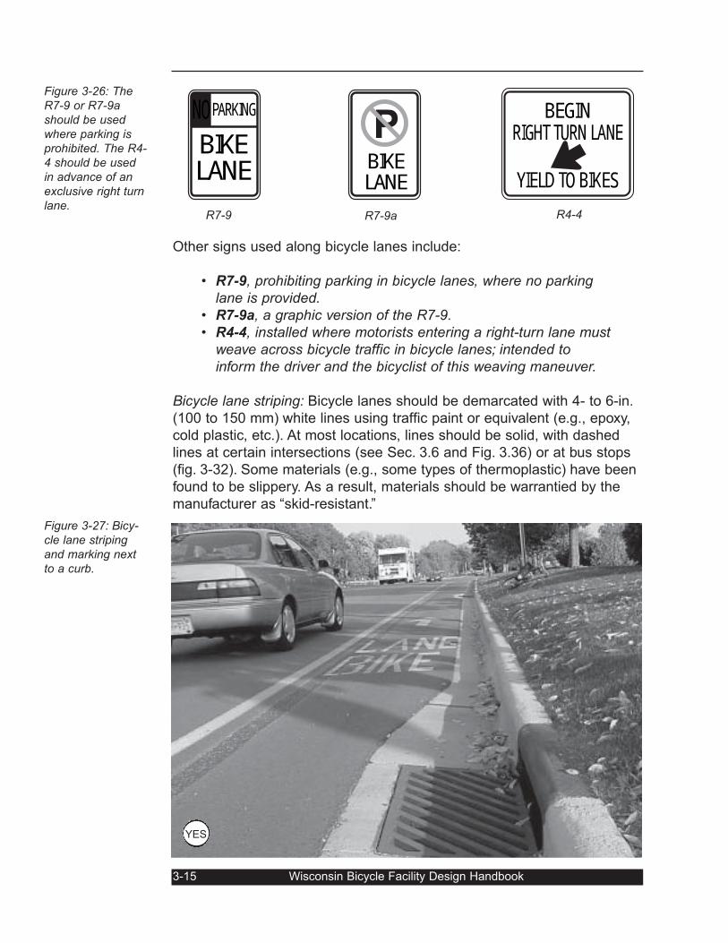
Other signs used along bicycle lanes include:
• R7-9, prohibiting parking in bicycle lanes, where no parkinglane is provided.
• R7-9a, a graphic version of the R7-9.• R4-4, installed where motorists entering a right-turn lane must
weave across bicycle traffic in bicycle lanes; intended toinform the driver and the bicyclist of this weaving maneuver.
Bicycle lane striping: Bicycle lanes should be demarcated with 4- to 6-in.
(100 to 150 mm) white lines using traffic paint or equivalent (e.g., epoxy,
cold plastic, etc.). At most locations, lines should be solid, with dashed
lines at certain intersections (see Sec. 3.6 and Fig. 3.36) or at bus stops
(fig. 3-32). Some materials (e.g., some types of thermoplastic) have been
found to be slippery. As a result, materials should be warrantied by the
manufacturer as “skid-resistant.”
3-15 Wisconsin Bicycle Facility Design Handbook
Figure 3-26: TheR7-9 or R7-9ashould be usedwhere parking isprohibited. The R4-4 should be usedin advance of anexclusive right turnlane.
Figure 3-27: Bicy-cle lane stripingand marking nextto a curb.
BIKELANEPARKINGNO
PBIKELANEBEGINRIGHT TURN LANE
YIELD TO BIKESR7-9 R7-9a R4-4
YES
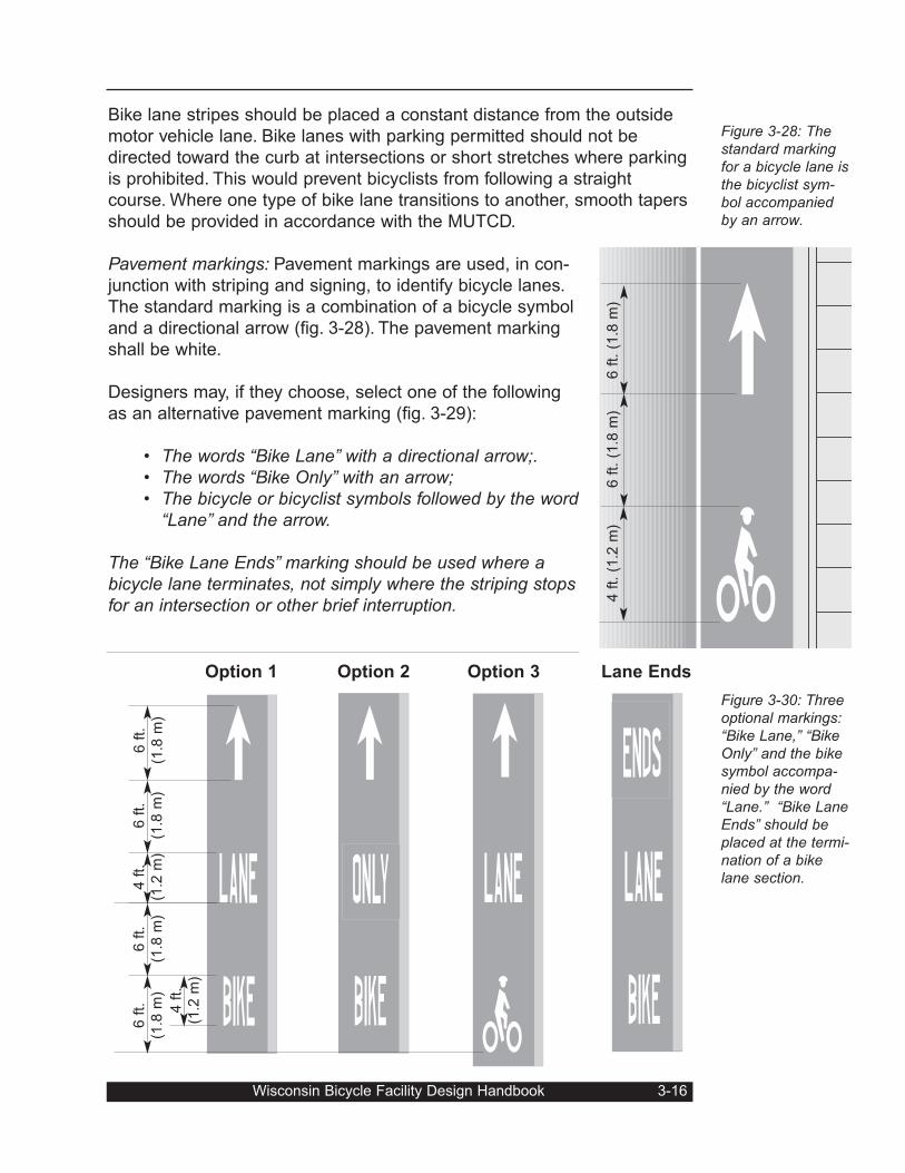
Bike lane stripes should be placed a constant distance from the outside
motor vehicle lane. Bike lanes with parking permitted should not be
directed toward the curb at intersections or short stretches where parking
is prohibited. This would prevent bicyclists from following a straight
course. Where one type of bike lane transitions to another, smooth tapers
should be provided in accordance with the MUTCD.
Pavement markings: Pavement markings are used, in con-
junction with striping and signing, to identify bicycle lanes.
The standard marking is a combination of a bicycle symbol
and a directional arrow (fig. 3-28). The pavement marking
shall be white.
Designers may, if they choose, select one of the following
as an alternative pavement marking (fig. 3-29):
• The words “Bike Lane” with a directional arrow;.• The words “Bike Only” with an arrow;• The bicycle or bicyclist symbols followed by the word
“Lane” and the arrow.
The “Bike Lane Ends” marking should be used where abicycle lane terminates, not simply where the striping stopsfor an intersection or other brief interruption.
Wisconsin Bicycle Facility Design Handbook 3-16
Figure 3-28: Thestandard markingfor a bicycle lane isthe bicyclist sym-bol accompaniedby an arrow.
Figure 3-30: Threeoptional markings:“Bike Lane,” “BikeOnly” and the bikesymbol accompa-nied by the word“Lane.” “Bike LaneEnds” should beplaced at the termi-nation of a bikelane section.
6 f
t. (
1.8
m)
6 f
t. (
1.8
m)
4 f
t. (
1.2
m)
6 f
t.
(1.8
m)
6 f
t.
(1.8
m)
4 f
t.
(1.2
m)
6 f
t.
(1.8
m)
6 f
t.
(1.8
m)
4 f
t.
(1.2
m)
Option 1 Option 2 Option 3 Lane Ends
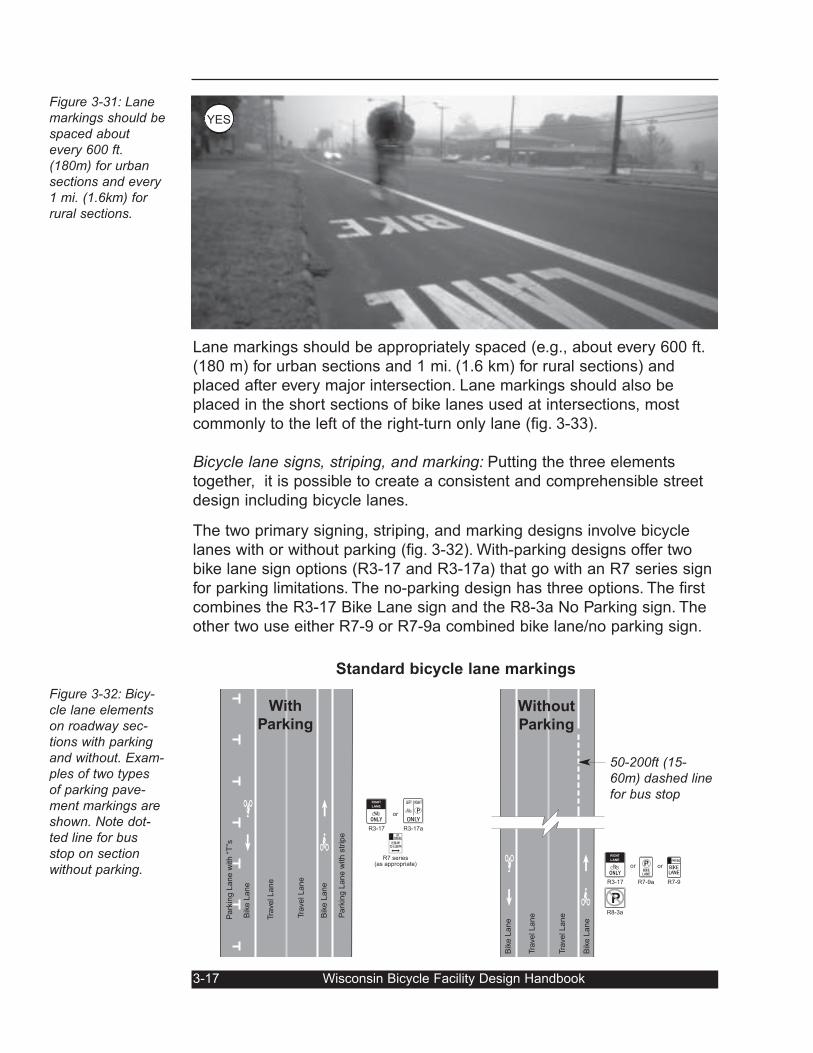
Lane markings should be appropriately spaced (e.g., about every 600 ft.
(180 m) for urban sections and 1 mi. (1.6 km) for rural sections) and
placed after every major intersection. Lane markings should also be
placed in the short sections of bike lanes used at intersections, most
commonly to the left of the right-turn only lane (fig. 3-33).
Bicycle lane signs, striping, and marking: Putting the three elements
together, it is possible to create a consistent and comprehensible street
design including bicycle lanes.
The two primary signing, striping, and marking designs involve bicycle
lanes with or without parking (fig. 3-32). With-parking designs offer two
bike lane sign options (R3-17 and R3-17a) that go with an R7 series sign
for parking limitations. The no-parking design has three options. The first
combines the R3-17 Bike Lane sign and the R8-3a No Parking sign. The
other two use either R7-9 or R7-9a combined bike lane/no parking sign.
Figure 3-31: Lanemarkings should bespaced aboutevery 600 ft.(180m) for urbansections and every1 mi. (1.6km) forrural sections.
Figure 3-32: Bicy-cle lane elementson roadway sec-tions with parkingand without. Exam-ples of two typesof parking pave-ment markings areshown. Note dot-ted line for busstop on sectionwithout parking.
Pa
rkin
g L
ane w
ith s
trip
e
Bik
e L
ane
Tra
vel Lane
Tra
vel Lane
Bik
e L
ane
Park
ing L
ane w
ith “
T”s
ONLY
RIGHT
LANE
R3-17 28:30 AMTO 5:30 PMHRPARKING
R7 series(as appropriate)
orPLEFT RIGHT
ONLYR3-17a
Bik
e L
ane
Tra
vel Lane
Tra
vel Lane
Bik
e L
ane
ONLY
RIGHT
LANE
R3-17
R8-3a
P
PBIKELANER7-9a
or BIKELANEPARKINGNO
or
R7-9
With
Parking
Without
Parking
3-17 Wisconsin Bicycle Facility Design Handbook
Standard bicycle lane markings
50-200ft (15-60m) dashed linefor bus stop
YES
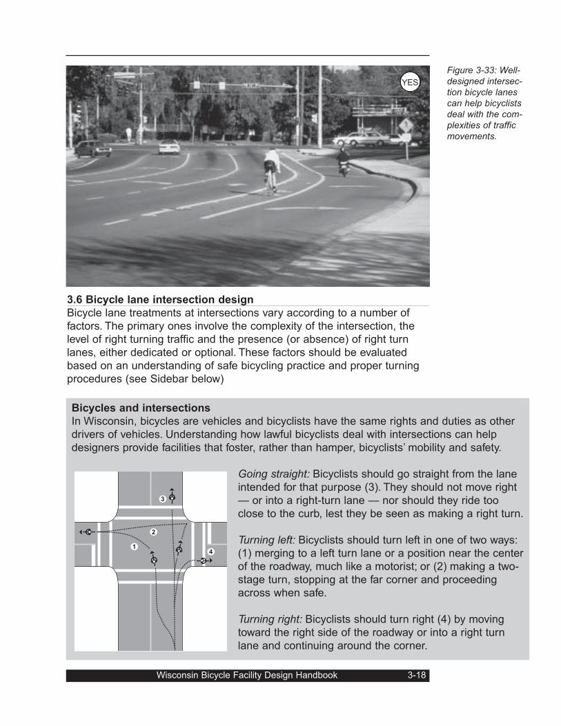
3.6 Bicycle lane intersection design
Bicycle lane treatments at intersections vary according to a number of
factors. The primary ones involve the complexity of the intersection, the
level of right turning traffic and the presence (or absence) of right turn
lanes, either dedicated or optional. These factors should be evaluated
based on an understanding of safe bicycling practice and proper turning
procedures (see Sidebar below)
Wisconsin Bicycle Facility Design Handbook 3-18
Figure 3-33: Well-designed intersec-tion bicycle lanescan help bicyclistsdeal with the com-plexities of trafficmovements.
Bicycles and intersections
In Wisconsin, bicycles are vehicles and bicyclists have the same rights and duties as other
drivers of vehicles. Understanding how lawful bicyclists deal with intersections can help
designers provide facilities that foster, rather than hamper, bicyclists’ mobility and safety.
Going straight: Bicyclists should go straight from the lane
intended for that purpose (3). They should not move right
— or into a right-turn lane — nor should they ride too
close to the curb, lest they be seen as making a right turn.
Turning left: Bicyclists should turn left in one of two ways:
(1) merging to a left turn lane or a position near the center
of the roadway, much like a motorist; or (2) making a two-
stage turn, stopping at the far corner and proceeding
across when safe.
Turning right: Bicyclists should turn right (4) by moving
toward the right side of the roadway or into a right turn
lane and continuing around the corner.
1
2
3
4
YES
Bike lane text should be placed immediately after, but not closer than 65
ft. (20 m) from, a crossroad. Placed too close to an intersection, the
markings may wear quickly due to crossing motor vehicle traffic. The
same is true for similar locations (e.g., major commercial driveways).
Markings may be placed at other locations as needed.
Simple intersections with few right turns: Most streets with bicycle lanes
intersect numerous minor cross streets. The intersections may be con-
trolled with stop signs on the side street and generally feature few con-
flicts and negligible levels of right turn
traffic from the bicycle lane street.
At such intersections, the dashed line
alternative is recommended. At inter-
sections with either no right-turning
traffic or extremely low levels of right-
turning traffic, the bicycle lanes may
be striped to the crosswalk and
dropped through the intersection (fig.
3-35). If there is no painted crosswalk,
the bike lane stripe should continue to
the extension of the adjacent property
line. Stripes should be picked up
beyond the intersection (fig. 3-34).
3-19 Wisconsin Bicycle Facility Design Handbook
Figure 3-34: Bicy-cle lane stripesshould start at themarked crosswalkor the extension ofthe adjacent prop-erty line.
Figure 3-35: Low-volume crossstreets with littleright turning trafficcan be treated withbasic striping,marking, and sig-nage. The imageat right shows asolid bike lane stripwithout parkingand with no rightturns.
ONLY
RIGHT
LANE
28:30 AMTO 5:30 PMHRPARKING
ONE WAY
ONLY
RIGHT
LANE
28:30 AMTO 5:30 PMHRPARKING
Solid bike lane stripe with
parking
Solid bike lane stripeat one-way street
crossing
Simple Intersections with few right turns
YES
YES OK
If there is a parking lane outside the bicycle lane, the bicycle lane stripe
should still be continued to the crosswalk (or extension of adjacent prop-
erty line). The parking lane markings, however, should be dropped the
appropriate distance from the intersection to allow proper sight distances.
Simple intersections with mod-erate right turn traffic: At other
minor intersections, right turn-
ing traffic is moderate but does
not warrant a dedicated turn
lane. In these cases, the solid
bicycle lane line should be
dropped and replaced with a
dashed line (fig. 3-36).
The dashed line should alter-
nate 2ft. (0.6m) dashes with
6ft. (1.8m) spaces. It should
begin between 50 and 200 feet
(15m - 60m) from the cross-
walk, depending on traffic
speeds.
Wisconsin Bicycle Facility Design Handbook 3-20
Figure 3-36: Withmoderate levels ofright-turning traffic,the bicycle laneshould be dashed.
Dashed bikelane stripe
with parking
Dashed bikelane stripe
without parking
Simple Intersections with moderately-light
to heavy right turn traffic
Right-turn lanes and bicycle lanesIntersections with right-turn lanes have always posed a challenge for bike lane designers.
In the early days, designers striped bike lanes to the right of right-turn lanes. Unfortunately,
this approach created a conflict point for bicyclists going straight and motorists turning right.
Moving the bicycle lane to the left
of the right-turn lane, however,
allowed designers to create a
merging area ahead of the inter-
section. This gave bicyclists and
motorists the opportunity to nego-
tiate to the proper position before
reaching the intersection.
The merging area could be long or
short, depending on motor vehicle
speeds and turning volumes. This
concept has formed the basis of
the current design approach to
right-turn lanes.
MergingArea
Early Approach Current Approach
3.7 Intersections with right-turn lanes
Right-turn lanes often complicate bicycle lane systems (see sidebar on
previous page). For this reason, designers should start a bike lane inter-
section project by first looking at the need for the right-turn lane. In some
cases, it may not be warranted and may be eliminated. If right-turn lanes
are warranted, there are several designs that can help get the bicycle
lane through such an intersection. Several factors help determine the best
approach.
Right-turn lanes and on-street parking: If the
bicycle lane street has on-street parking,
dropping the parking lane can create most
of the space required for the right turn lane.
And, in many cases, the bicycle lane will
only have to shift slightly to the left (fig. 3-
38). Lane striping should be solid in the stor-
age area and dashed in the taper. Lengths
of each should be determined based on
right-turn lane requirements (see below).
A second dashed line may be used to delin-
eate the right side of the bicycle lane.
3-21 Wisconsin Bicycle Facility Design Handbook
Figure 3-37: Thisintersection fea-tures a bicycle laneto the left of aright-turn lane.Note how it linesup with the bicyclelane on the far sideof the intersection.
Figure 3-38: Abicycle lane instal-lation where aright-turn lanereplaces on-streetparking at theintersection.
ONLY
BEGINRIGHT TURN LANEYIELD TO BIKES
R4-4
RIGHT LANE
TURN RIGHT
MUST
R3-7R
Optional
LT
L = Storage length required for right turnsT = Taper length needed for motorists to merge (to be cal-
culated based on standard right-turn configuration)
After Figure 121, Oregon Bicycle/Pedestrian Plan, 1996
Tip
In some cases, ithelps to think ofthe bicycle laneand the rightthrough lane as apair. When thethrough laneshifts one way orthe other — tocreate a turn laneor a parking lane,for example —the bicycle laneshifts as well.
YES
R4-4
R3-7R
Right-turn lanes on widened roadwayswith no on-street parking: In many cases,
the street with bicycle lanes has no on-
street parking, but the roadway widens to
accept the right-turn lane. In these situa-
tions, the bicycle lane should continue
across with a dashed line. The length of
the right-turn storage area and the taper
will determine the length of the dashed
line. A second dashed line may be used to
delineate the right side of the bicycle lane.
Right-turn lanes on roadways where rightthrough lane is dropped: Roadways where
the right through lane is dropped to create
the right-turn lane are more difficult situa-
tions to deal with. In these cases, the bicy-
cle lane must move to the left, the width of
a travel lane. Dropping the right bicycle
lane line in this merging zone is an accept-
able alternative (fig. 3-40).
Another approach is to stop the curb bicy-
cle lane’s solid stripe at the merge zone,
replacing it with a dashed line. The bicycle
lane to the left of the right-turn lane should
then begin with a dashed line (fig. 3-41).
Right turn lane next to optional right turnlane: Optional right-turn lanes create addi-
tional problems because the path of the
occupying motor vehicle may be either
straight or right. As a result, a bicycle lane
should not be striped to the right of the
optional right-turn lane. Nor should it be
striped to the left. In these cases, re-evalu-
ating the warrants for the optional lane
should be considered. Oth-
erwise, the bicycle lane
should be dropped until
after the intersection. A
W11-1 warning sign,
accompanied by a W11-16
(“Share the Road”) subplate
may be used.
Wisconsin Bicycle Facility Design Handbook 3-22
Figure 3-39: Thisroadway has beenwidened for a rightturn lane. The bicy-cle lane shouldcontinue across thetaper as shownwith a dashed line.
Figure 3-40: Wherethe right throughlane becomes theright turn lane,dropping the lanestripes in themerge zone is anacceptableapproach.
Figure 3-41 (belowright): Anotherapproach is todash the approach-ing bicycle laneline part waythrough the mergezone and dot theright line of theintersection bikelane to match.
Figure 3-42 (belowleft): The “Sharethe road” sign com-bination.
ONLY
BEGINRIGHT TURN LANEYIELD TO BIKES
RIGHT LANE
TURN RIGHT
MUST
Optional
LT
ONLY
BEGINRIGHT TURN LANEYIELD TO BIKES
R4-4
RIGHT LANE
TURN RIGHT
MUST
R3-7R
ONLY
BEGINRIGHT TURN LANEYIELD TO BIKES
R4-4
RIGHT LANE
TURN RIGHT
MUST
R3-7R
LL
D2
D1
T
L = Storage lengthrequired forright turns
T = Taper lengthneeded formotorists tomerge
L = Storage lengthrequired forright turns
D1, D2 = Distanceneeded forbicyclists tomerge left (tobe field-deter-mined for eachcase)After Figure 122, Oregon
Bicycle/Pedestrian Plan, 1996
SHARETHEROADW11-1, W11-16
R4-4
R4-4
R4-4
R3-7R
R3-7R
R3-7R
3.8 Left-turn bicycle lane
Bicyclists making left turns will sometimes
use the two-stage turn (see “Bicycles and
intersections” on p. 3-19), crossing the
intersection and stopping at the far side
before continuing. Or they may move into a
vehicular left turn position (e.g., in the left
turn lane) and turn from there. In most
cases, there is no particular bicycle facility
required to support either of these two
options.
Where there are numerous left-turning
bicyclists, however, one approach is to
provide a separate bicycle left-turn lane,
as shown in Figure 3-43.
There are several advantages to this
design. For example, it can free up space
in the motor vehicle left-turn lane. It can
also provide space for more left turning
bicyclists. Note the optional dashed line
through the intersection. This provides
guidance for the bicyclists making their
left turn.
3-23 Wisconsin Bicycle Facility Design Handbook
Figure 3-42: Abicycle left-turnlane can helpserve heavy bicy-cle traffic.
Figure 3-43: Asshown in this illus-tration, dashedlines may be usedto lead bicyclists tothe destinationbicycle lane.
ONLYONLY
ONLY ONLY
Optional
OK
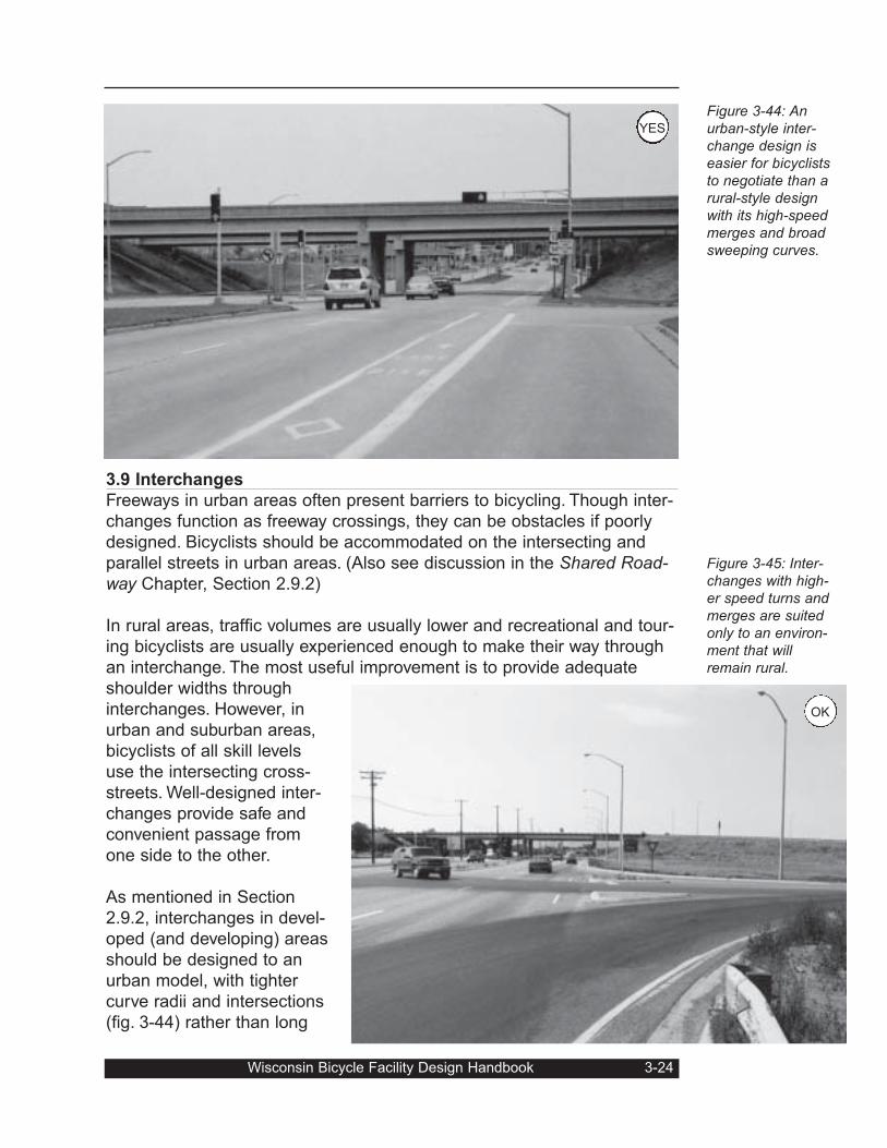
3.9 Interchanges
Freeways in urban areas often present barriers to bicycling. Though inter-
changes function as freeway crossings, they can be obstacles if poorly
designed. Bicyclists should be accommodated on the intersecting and
parallel streets in urban areas. (Also see discussion in the Shared Road-way Chapter, Section 2.9.2)
In rural areas, traffic volumes are usually lower and recreational and tour-
ing bicyclists are usually experienced enough to make their way through
an interchange. The most useful improvement is to provide adequate
shoulder widths through
interchanges. However, in
urban and suburban areas,
bicyclists of all skill levels
use the intersecting cross-
streets. Well-designed inter-
changes provide safe and
convenient passage from
one side to the other.
As mentioned in Section
2.9.2, interchanges in devel-
oped (and developing) areas
should be designed to an
urban model, with tighter
curve radii and intersections
(fig. 3-44) rather than long
Wisconsin Bicycle Facility Design Handbook 3-24
Figure 3-44: Anurban-style inter-change design iseasier for bicycliststo negotiate than arural-style designwith its high-speedmerges and broadsweeping curves.
Figure 3-45: Inter-changes with high-er speed turns andmerges are suitedonly to an environ-ment that willremain rural.
OK
YES
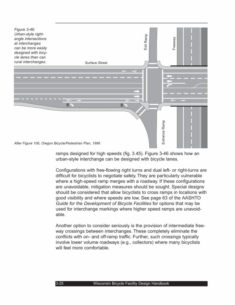
ramps designed for high speeds (fig. 3.45). Figure 3-46 shows how an
urban-style interchange can be designed with bicycle lanes.
Configurations with free-flowing right turns and dual left- or right-turns are
difficult for bicyclists to negotiate safely. They are particularly vulnerable
where a high-speed ramp merges with a roadway. If these configurations
are unavoidable, mitigation measures should be sought. Special designs
should be considered that allow bicyclists to cross ramps in locations with
good visibility and where speeds are low. See page 63 of the AASHTO
Guide for the Development of Bicycle Facilities for options that may be
used for interchange markings where higher speed ramps are unavoid-
able.
Another option to consider seriously is the provision of intermediate free-
way crossings between interchanges. These completely eliminate the
conflicts with on- and off-ramp traffic. Further, such crossings typically
involve lower volume roadways (e.g., collectors) where many bicyclists
will feel more comfortable.
ONLYONLY
3-25 Wisconsin Bicycle Facility Design Handbook
After Figure 106, Oregon Bicycle/Pedestrian Plan, 1996
Figure 3-46:Urban-style right-angle intersectionsat interchangescan be more easilydesigned with bicy-cle lanes than canrural interchanges.
Exit R
am
p
Fre
ew
ay
Surface Street
Entr
ance R
am
p

Wisconsin Bicycle Facility Design Handbook 3-26
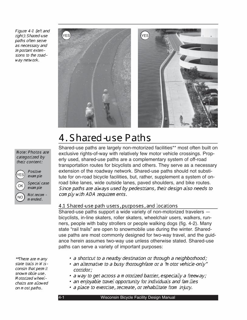
4. Shared-use PathsShared-use paths are largely non-motorized facilities** most often built onexclusive rights-of-way with relatively few motor vehicle crossings. Prop-erly used, shared-use paths are a complementary system of off-roadtransportation routes for bicyclists and others. They serve as a necessaryextension of the roadway network. Shared-use paths should not substi-tute for on-road bicycle facilities, but, rather, supplement a system of on-road bike lanes, wide outside lanes, paved shoulders, and bike routes.Since paths are always used by pedestrians, their design also needs tocomply with ADA requirements.4.1 Shared-use path users, purposes, and locationsShared-use paths support a wide variety of non-motorized travelers —bicyclists, in-line skaters, roller skaters, wheelchair users, walkers, run-ners, people with baby strollers or people walking dogs (fig. 4-2). Manystate “rail trails” are open to snowmobile use during the winter. Shared-use paths are most commonly designed for two-way travel, and the guid-ance herein assumes two-way use unless otherwise stated. Shared-usepaths can serve a variety of important purposes:
• a shortcut to a nearby destination or through a neighborhood;• an alternative to a busy thoroughfare or a “motor vehicle-only”corridor;• a way to get across a motorized barrier, especially a freeway;• an enjoyable travel opportunity for individuals and families• a place to exercise, recreate, or rehabilitate from injury.4-1 Wisconsin Bicycle Facility Design Manual
Figure 4-1 (left andright): Shared-usepaths often serveas necessary andimportant exten-sions to the road-way network.
**There are manystate trails in Wis-consin that permitsnowmobile use.Motorized wheel-chairs are allowedon most paths.
Note: Photos arecategorized bytheir content:PositiveexampleSpecial caseexampleNot recom-mended.
YES
OK
NO
YESYES
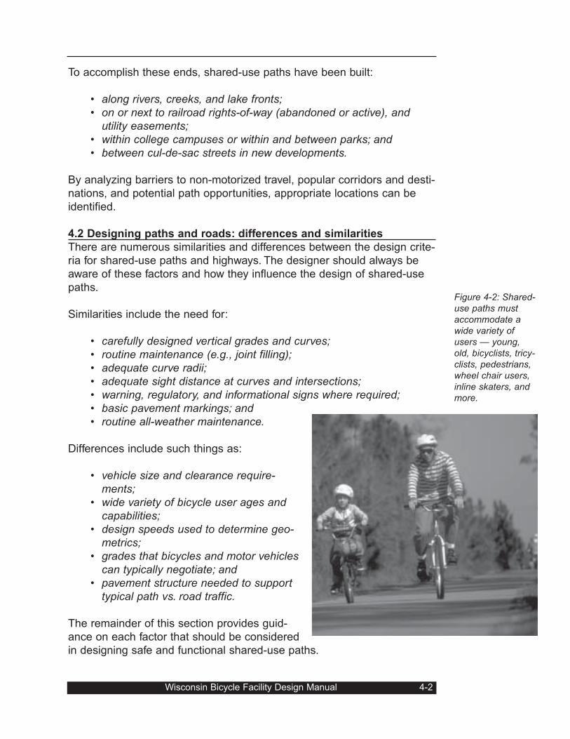
To accomplish these ends, shared-use paths have been built:
• along rivers, creeks, and lake fronts;• on or next to railroad rights-of-way (abandoned or active), and
utility easements;• within college campuses or within and between parks; and• between cul-de-sac streets in new developments.
By analyzing barriers to non-motorized travel, popular corridors and desti-
nations, and potential path opportunities, appropriate locations can be
identified.
4.2 Designing paths and roads: differences and similarities
There are numerous similarities and differences between the design crite-
ria for shared-use paths and highways. The designer should always be
aware of these factors and how they influence the design of shared-use
paths.
Similarities include the need for:
• carefully designed vertical grades and curves;• routine maintenance (e.g., joint filling);• adequate curve radii;• adequate sight distance at curves and intersections;• warning, regulatory, and informational signs where required;• basic pavement markings; and• routine all-weather maintenance.
Differences include such things as:
• vehicle size and clearance require-ments;
• wide variety of bicycle user ages andcapabilities;
• design speeds used to determine geo-metrics;
• grades that bicycles and motor vehiclescan typically negotiate; and
• pavement structure needed to supporttypical path vs. road traffic.
The remainder of this section provides guid-
ance on each factor that should be considered
in designing safe and functional shared-use paths.
Wisconsin Bicycle Facility Design Manual 4-2
Figure 4-2: Shared-use paths mustaccommodate awide variety ofusers — young,old, bicyclists, tricy-clists, pedestrians,wheel chair users,inline skaters, andmore.
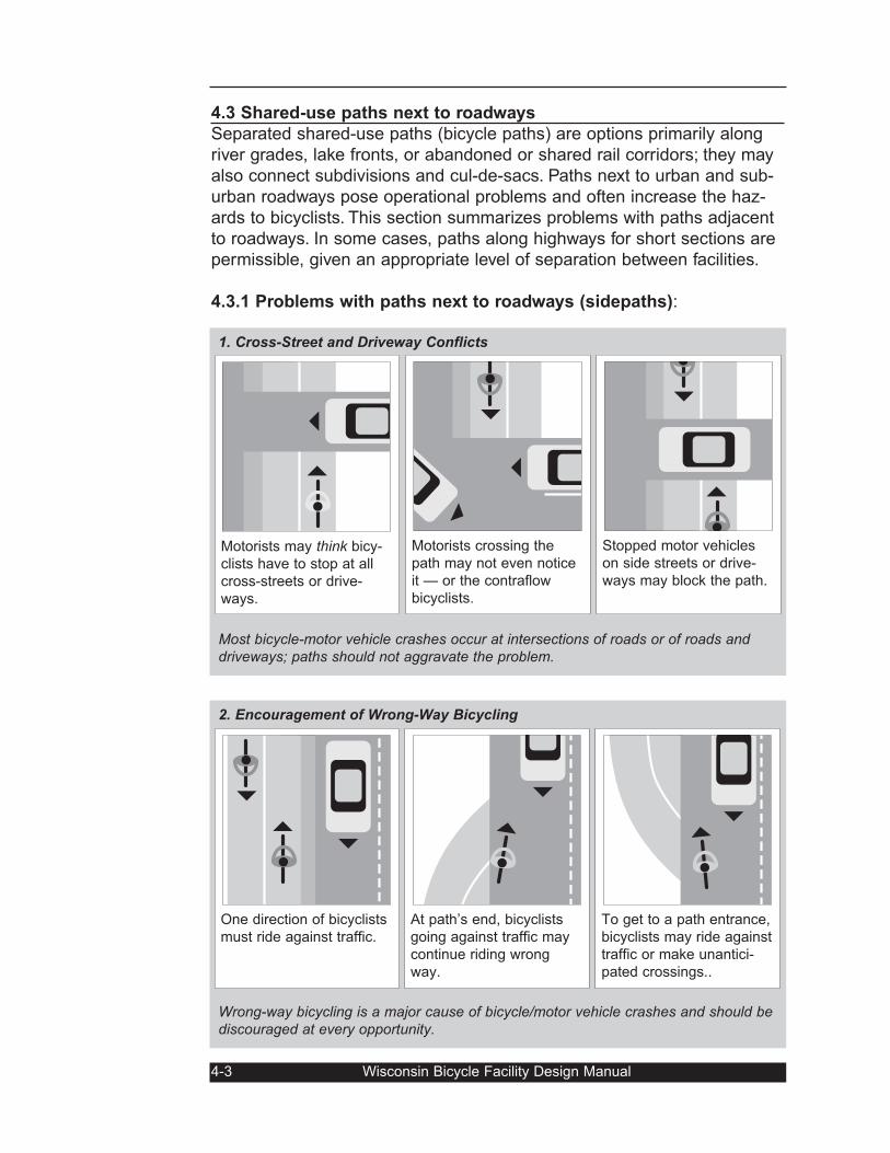
4.3 Shared-use paths next to roadways
Separated shared-use paths (bicycle paths) are options primarily along
river grades, lake fronts, or abandoned or shared rail corridors; they may
also connect subdivisions and cul-de-sacs. Paths next to urban and sub-
urban roadways pose operational problems and often increase the haz-
ards to bicyclists. This section summarizes problems with paths adjacent
to roadways. In some cases, paths along highways for short sections are
permissible, given an appropriate level of separation between facilities.
4.3.1 Problems with paths next to roadways (sidepaths):
4-3 Wisconsin Bicycle Facility Design Manual
2. Encouragement of Wrong-Way Bicycling
Wrong-way bicycling is a major cause of bicycle/motor vehicle crashes and should bediscouraged at every opportunity.
1. Cross-Street and Driveway Conflicts
Most bicycle-motor vehicle crashes occur at intersections of roads or of roads anddriveways; paths should not aggravate the problem.
At path’s end, bicyclists
going against traffic may
continue riding wrong
way.
To get to a path entrance,
bicyclists may ride against
traffic or make unantici-
pated crossings..
One direction of bicyclists
must ride against traffic.
Stopped motor vehicles
on side streets or drive-
ways may block the path.
Motorists crossing the
path may not even notice
it — or the contraflow
bicyclists.
Motorists may think bicy-
clists have to stop at all
cross-streets or drive-
ways.
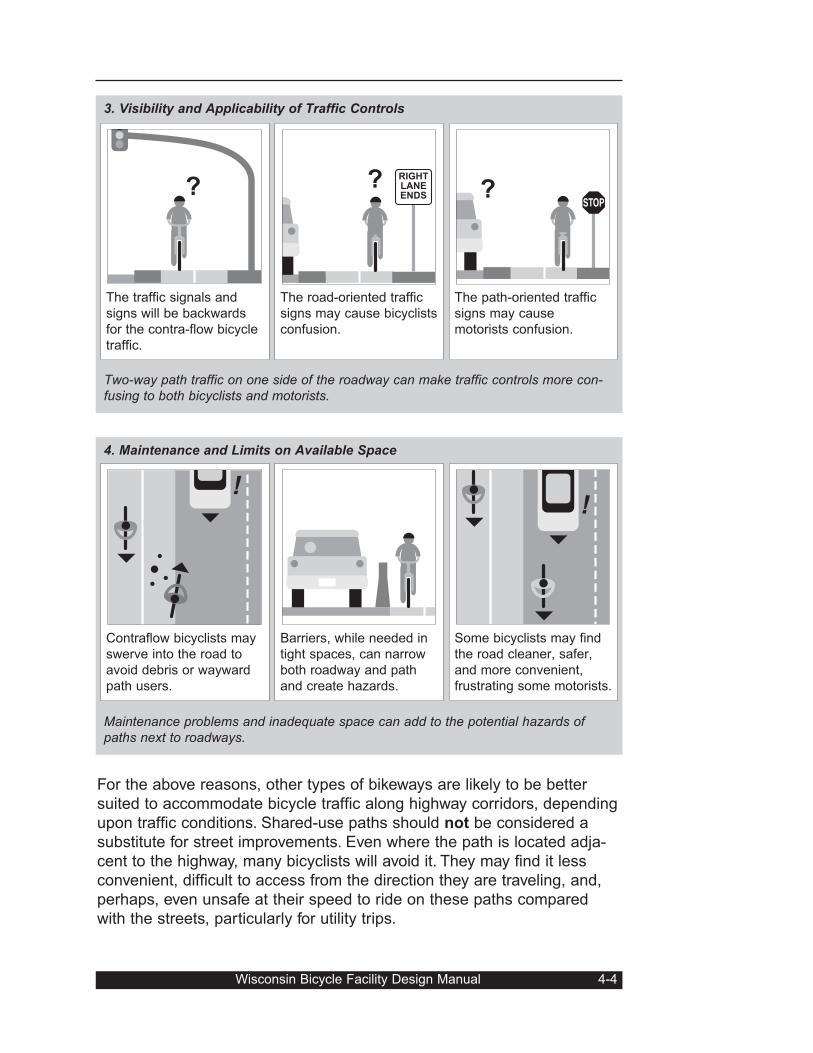
For the above reasons, other types of bikeways are likely to be better
suited to accommodate bicycle traffic along highway corridors, depending
upon traffic conditions. Shared-use paths should not be considered a
substitute for street improvements. Even where the path is located adja-
cent to the highway, many bicyclists will avoid it. They may find it less
convenient, difficult to access from the direction they are traveling, and,
perhaps, even unsafe at their speed to ride on these paths compared
with the streets, particularly for utility trips.
Wisconsin Bicycle Facility Design Manual 4-4
3. Visibility and Applicability of Traffic Controls
Two-way path traffic on one side of the roadway can make traffic controls more con-fusing to both bicyclists and motorists.
4. Maintenance and Limits on Available Space
Maintenance problems and inadequate space can add to the potential hazards ofpaths next to roadways.
The path-oriented traffic
signs may cause
motorists confusion.
?
The road-oriented traffic
signs may cause bicyclists
confusion.
? RIGHTLANEENDS
The traffic signals and
signs will be backwards
for the contra-flow bicycle
traffic.
?
Contraflow bicyclists may
swerve into the road to
avoid debris or wayward
path users.
!
Barriers, while needed in
tight spaces, can narrow
both roadway and path
and create hazards.
Some bicyclists may find
the road cleaner, safer,
and more convenient,
frustrating some motorists.
!
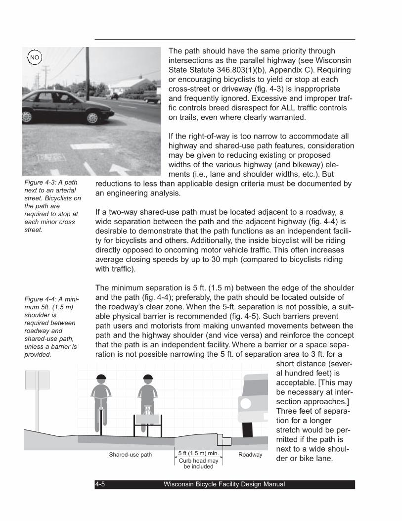
The path should have the same priority through
intersections as the parallel highway (see Wisconsin
State Statute 346.803(1)(b), Appendix C). Requiring
or encouraging bicyclists to yield or stop at each
cross-street or driveway (fig. 4-3) is inappropriate
and frequently ignored. Excessive and improper traf-
fic controls breed disrespect for ALL traffic controls
on trails, even where clearly warranted.
If the right-of-way is too narrow to accommodate all
highway and shared-use path features, consideration
may be given to reducing existing or proposed
widths of the various highway (and bikeway) ele-
ments (i.e., lane and shoulder widths, etc.). But
reductions to less than applicable design criteria must be documented by
an engineering analysis.
If a two-way shared-use path must be located adjacent to a roadway, a
wide separation between the path and the adjacent highway (fig. 4-4) is
desirable to demonstrate that the path functions as an independent facili-
ty for bicyclists and others. Additionally, the inside bicyclist will be riding
directly opposed to oncoming motor vehicle traffic. This often increases
average closing speeds by up to 30 mph (compared to bicyclists riding
with traffic).
The minimum separation is 5 ft. (1.5 m) between the edge of the shoulder
and the path (fig. 4-4); preferably, the path should be located outside of
the roadway’s clear zone. When the 5-ft. separation is not possible, a suit-
able physical barrier is recommended (fig. 4-5). Such barriers prevent
path users and motorists from making unwanted movements between the
path and the highway shoulder (and vice versa) and reinforce the concept
that the path is an independent facility. Where a barrier or a space sepa-
ration is not possible narrowing the 5 ft. of separation area to 3 ft. for a
short distance (sever-
al hundred feet) is
acceptable. [This may
be necessary at inter-
section approaches.]
Three feet of separa-
tion for a longer
stretch would be per-
mitted if the path is
next to a wide shoul-
der or bike lane.
4-5 Wisconsin Bicycle Facility Design Manual
Figure 4-3: A pathnext to an arterialstreet. Bicyclists onthe path arerequired to stop ateach minor crossstreet.
Figure 4-4: A mini-mum 5ft. (1.5 m)shoulder isrequired betweenroadway andshared-use path,unless a barrier isprovided.
Shared-use path Roadway5 ft (1.5 m) min.
Curb head maybe included
NO
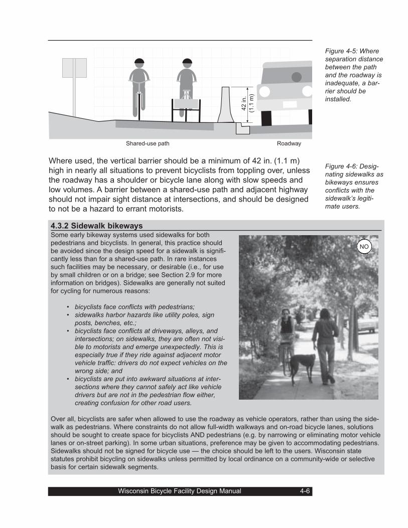
Where used, the vertical barrier should be a minimum of 42 in. (1.1 m)
high in nearly all situations to prevent bicyclists from toppling over, unless
the roadway has a shoulder or bicycle lane along with slow speeds and
low volumes. A barrier between a shared-use path and adjacent highway
should not impair sight distance at intersections, and should be designed
to not be a hazard to errant motorists.
Wisconsin Bicycle Facility Design Manual 4-6
Figure 4-5: Whereseparation distancebetween the pathand the roadway isinadequate, a bar-rier should beinstalled.
Figure 4-6: Desig-nating sidewalks asbikeways ensuresconflicts with thesidewalk’s legiti-mate users.
Shared-use path Roadway
42 in.
(1.1
m)
4.3.2 Sidewalk bikewaysSome early bikeway systems used sidewalks for both
pedestrians and bicyclists. In general, this practice should
be avoided since the design speed for a sidewalk is signifi-
cantly less than for a shared-use path. In rare instances
such facilities may be necessary, or desirable (i.e., for use
by small children or on a bridge; see Section 2.9 for more
information on bridges). Sidewalks are generally not suited
for cycling for numerous reasons:
• bicyclists face conflicts with pedestrians;• sidewalks harbor hazards like utility poles, sign
posts, benches, etc.;• bicyclists face conflicts at driveways, alleys, and
intersections; on sidewalks, they are often not visi-ble to motorists and emerge unexpectedly. This isespecially true if they ride against adjacent motorvehicle traffic: drivers do not expect vehicles on thewrong side; and
• bicyclists are put into awkward situations at inter-sections where they cannot safely act like vehicledrivers but are not in the pedestrian flow either, creating confusion for other road users.
Over all, bicyclists are safer when allowed to use the roadway as vehicle operators, rather than using the side-
walk as pedestrians. Where constraints do not allow full-width walkways and on-road bicycle lanes, solutions
should be sought to create space for bicyclists AND pedestrians (e.g. by narrowing or eliminating motor vehicle
lanes or on-street parking). In some urban situations, preference may be given to accommodating pedestrians.
Sidewalks should not be signed for bicycle use — the choice should be left to the users. Wisconsin state
statutes prohibit bicycling on sidewalks unless permitted by local ordinance on a community-wide or selective
basis for certain sidewalk segments.
NO
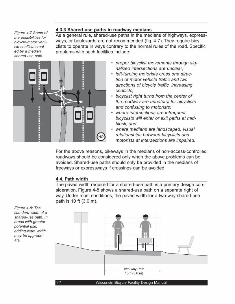
4.3.3 Shared-use paths in roadway medians
As a general rule, shared-use paths in the medians of highways, express-
ways, or boulevards are not recommended (fig. 4-7). They require bicy-
clists to operate in ways contrary to the normal rules of the road. Specific
problems with such facilities include:
• proper bicyclist movements through sig-nalized intersections are unclear;
• left-turning motorists cross one direc-tion of motor vehicle traffic and twodirections of bicycle traffic, increasingconflicts;
• bicyclist right turns from the center ofthe roadway are unnatural for bicyclistsand confusing to motorists;
• where intersections are infrequent,bicyclists will enter or exit paths at mid-block; and
• where medians are landscaped, visualrelationships between bicyclists andmotorists at intersections are impaired.
For the above reasons, bikeways in the medians of non-access-controlled
roadways should be considered only when the above problems can be
avoided. Shared-use paths should only be provided in the medians of
freeways or expressways if crossings can be avoided.
4.4. Path width
The paved width required for a shared-use path is a primary design con-
sideration. Figure 4-8 shows a shared-use path on a separate right of
way. Under most conditions, the paved width for a two-way shared-use
path is 10 ft (3.0 m).
4-7 Wisconsin Bicycle Facility Design Manual
Figure 4-7 Some ofthe possibilities forbicycle-motor vehi-cle conflicts creat-ed by a medianshared-use path
Figure 4-8: Thestandard width of ashared-use path. Inareas with greaterpotential use,adding extra widthmay be appropri-ate.
Two-way Path
10 ft (3.0 m)
NO
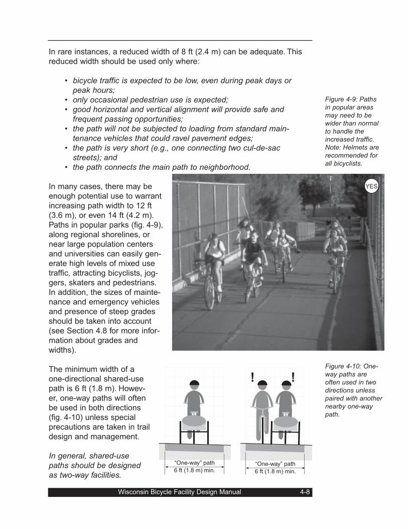
In rare instances, a reduced width of 8 ft (2.4 m) can be adequate. This
reduced width should be used only where:
• bicycle traffic is expected to be low, even during peak days orpeak hours;
• only occasional pedestrian use is expected;• good horizontal and vertical alignment will provide safe and
frequent passing opportunities;• the path will not be subjected to loading from standard main-
tenance vehicles that could ravel pavement edges;• the path is very short (e.g., one connecting two cul-de-sac
streets); and• the path connects the main path to neighborhood.
In many cases, there may be
enough potential use to warrant
increasing path width to 12 ft
(3.6 m), or even 14 ft (4.2 m).
Paths in popular parks (fig. 4-9),
along regional shorelines, or
near large population centers
and universities can easily gen-
erate high levels of mixed use
traffic, attracting bicyclists, jog-
gers, skaters and pedestrians.
In addition, the sizes of mainte-
nance and emergency vehicles
and presence of steep grades
should be taken into account
(see Section 4.8 for more infor-
mation about grades and
widths).
The minimum width of a
one-directional shared-use
path is 6 ft (1.8 m). Howev-
er, one-way paths will often
be used in both directions
(fig. 4-10) unless special
precautions are taken in trail
design and management.
In general, shared-usepaths should be designedas two-way facilities.
Wisconsin Bicycle Facility Design Manual 4-8
Figure 4-9: Pathsin popular areasmay need to bewider than normalto handle theincreased traffic.Note: Helmets arerecommended forall bicyclists.
Figure 4-10: One-way paths areoften used in twodirections unlesspaired with anothernearby one-waypath.
“One-way” path
6 ft (1.8 m) min.
!!
“One-way” path
6 ft (1.8 m) min.
YES
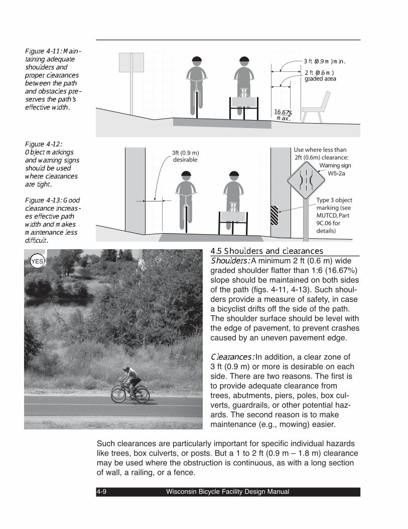
4.5 Shoulders and clearances Shoulders: A minimum 2 ft (0.6 m) widegraded shoulder flatter than 1:6 (16.67%)slope should be maintained on both sidesof the path (figs. 4-11, 4-13). Such shoul-ders provide a measure of safety, in casea bicyclist drifts off the side of the path.The shoulder surface should be level withthe edge of pavement, to prevent crashescaused by an uneven pavement edge.Clearances: In addition, a clear zone of3 ft (0.9 m) or more is desirable on eachside. There are two reasons. The first isto provide adequate clearance fromtrees, abutments, piers, poles, box cul-verts, guardrails, or other potential haz-ards. The second reason is to makemaintenance (e.g., mowing) easier.
Such clearances are particularly important for specific individual hazardslike trees, box culverts, or posts. But a 1 to 2 ft (0.9 m – 1.8 m) clearancemay be used where the obstruction is continuous, as with a long sectionof wall, a railing, or a fence.4-9 Wisconsin Bicycle Facility Design Manual
Figure 4-11: Main-taining adequateshoulders andproper clearancesbetween the pathand obstacles pre-serves the path’seffective width.
Figure 4-12:Object markingsand warning signsshould be usedwhere clearancesare tight.Figure 4-13: Goodclearance increas-es effective pathwidth and makesmaintenance lessdifficult.
Warning sign
W5-2a
3ft (0.9 m)
Type 3 object
marking (see
MUTCD, Part
9C.06 for
details)
desirable
Use where less than
2ft (0.6m) clearance:
2 ft (0.6 m)graded area3 ft (0.9 m) min.
16.67%max.
YES
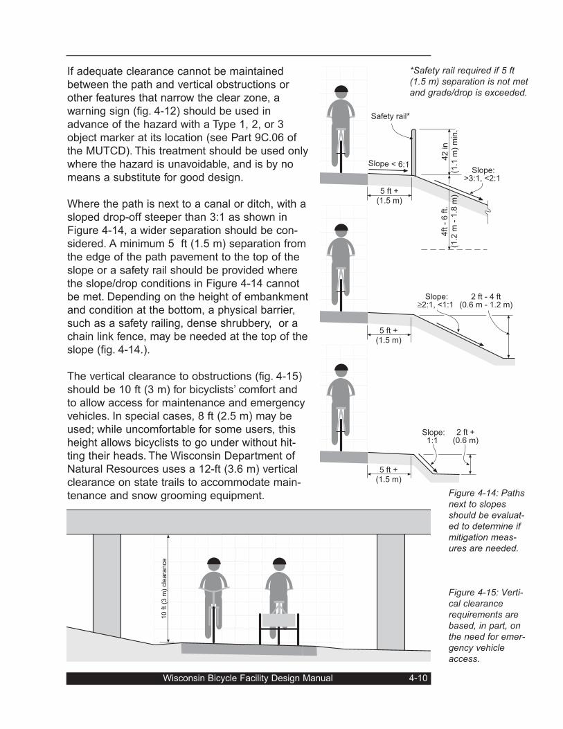
If adequate clearance cannot be maintained
between the path and vertical obstructions or
other features that narrow the clear zone, a
warning sign (fig. 4-12) should be used in
advance of the hazard with a Type 1, 2, or 3
object marker at its location (see Part 9C.06 of
the MUTCD). This treatment should be used only
where the hazard is unavoidable, and is by no
means a substitute for good design.
Where the path is next to a canal or ditch, with a
sloped drop-off steeper than 3:1 as shown in
Figure 4-14, a wider separation should be con-
sidered. A minimum 5 ft (1.5 m) separation from
the edge of the path pavement to the top of the
slope or a safety rail should be provided where
the slope/drop conditions in Figure 4-14 cannot
be met. Depending on the height of embankment
and condition at the bottom, a physical barrier,
such as a safety railing, dense shrubbery, or a
chain link fence, may be needed at the top of the
slope (fig. 4-14.).
The vertical clearance to obstructions (fig. 4-15)
should be 10 ft (3 m) for bicyclists’ comfort and
to allow access for maintenance and emergency
vehicles. In special cases, 8 ft (2.5 m) may be
used; while uncomfortable for some users, this
height allows bicyclists to go under without hit-
ting their heads. The Wisconsin Department of
Natural Resources uses a 12-ft (3.6 m) vertical
clearance on state trails to accommodate main-
tenance and snow grooming equipment.
Wisconsin Bicycle Facility Design Manual 4-10
Figure 4-14: Pathsnext to slopesshould be evaluat-ed to determine ifmitigation meas-ures are needed.
Figure 4-15: Verti-cal clearancerequirements arebased, in part, onthe need for emer-gency vehicleaccess.
2 ft - 4 ft(0.6 m - 1.2 m)
5 ft +(1.5 m)
2 ft +(0.6 m)
5 ft +(1.5 m)
42 in
(1.1
m)
min
.
Safety rail*
4ft -
6 ft.
(1.2
m -
1.8
m)
Slope:>3:1, <2:1
Slope < 6:1
Slope:≥2:1, <1:1
5 ft +(1.5 m)
Slope:1:1
10
ft
(3 m
) cle
ara
nce
*Safety rail required if 5 ft(1.5 m) separation is not metand grade/drop is exceeded.
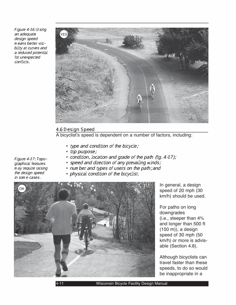
4.6 Design SpeedA bicyclistʼs speed is dependent on a number of factors, including:
• type and condition of the bicycle; • trip purpose;• condition, location and grade of the path (fig. 4-17);• speed and direction of any prevailing winds;• number and types of users on the path; and• physical condition of the bicyclist. In general, a designspeed of 20 mph (30km/h) should be used. For paths on longdowngrades(i.e., steeper than 4%and longer than 500 ft(150 m)), a designspeed of 30 mph (50km/h) or more is advis-able (Section 4.8).Although bicyclists cantravel faster than thesespeeds, to do so wouldbe inappropriate in a
4-11 Wisconsin Bicycle Facility Design Manual
Figure 4-16: Usingan adequatedesign speedmeans better visi-bility at curves anda reduced potentialfor unexpectedconflicts.
Figure 4-17: Topo-graphical featuresmay require raisingthe design speedin some cases.OK
YES
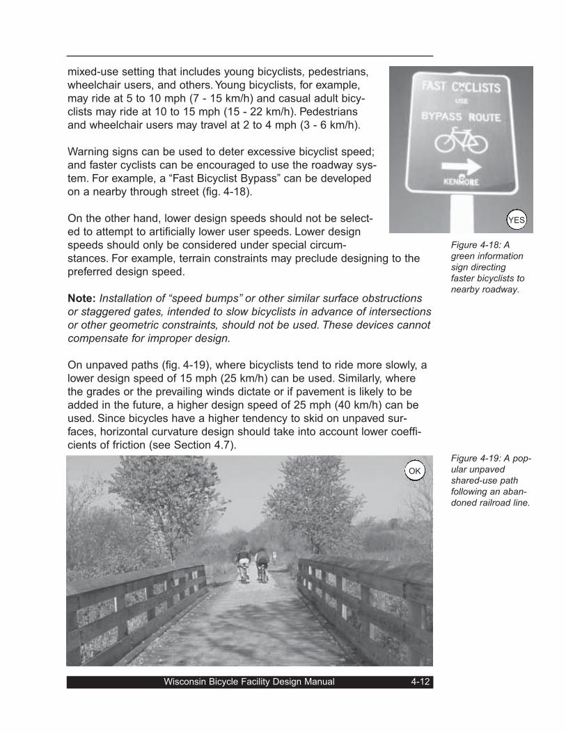
mixed-use setting that includes young bicyclists, pedestrians,
wheelchair users, and others. Young bicyclists, for example,
may ride at 5 to 10 mph (7 - 15 km/h) and casual adult bicy-
clists may ride at 10 to 15 mph (15 - 22 km/h). Pedestrians
and wheelchair users may travel at 2 to 4 mph (3 - 6 km/h).
Warning signs can be used to deter excessive bicyclist speed;
and faster cyclists can be encouraged to use the roadway sys-
tem. For example, a “Fast Bicyclist Bypass” can be developed
on a nearby through street (fig. 4-18).
On the other hand, lower design speeds should not be select-
ed to attempt to artificially lower user speeds. Lower design
speeds should only be considered under special circum-
stances. For example, terrain constraints may preclude designing to the
preferred design speed.
Note: Installation of “speed bumps” or other similar surface obstructionsor staggered gates, intended to slow bicyclists in advance of intersectionsor other geometric constraints, should not be used. These devices cannotcompensate for improper design.
On unpaved paths (fig. 4-19), where bicyclists tend to ride more slowly, a
lower design speed of 15 mph (25 km/h) can be used. Similarly, where
the grades or the prevailing winds dictate or if pavement is likely to be
added in the future, a higher design speed of 25 mph (40 km/h) can be
used. Since bicycles have a higher tendency to skid on unpaved sur-
faces, horizontal curvature design should take into account lower coeffi-
cients of friction (see Section 4.7).
Wisconsin Bicycle Facility Design Manual 4-12
Figure 4-18: Agreen informationsign directingfaster bicyclists tonearby roadway.
Figure 4-19: A pop-ular unpavedshared-use pathfollowing an aban-doned railroad line.
OK
YES
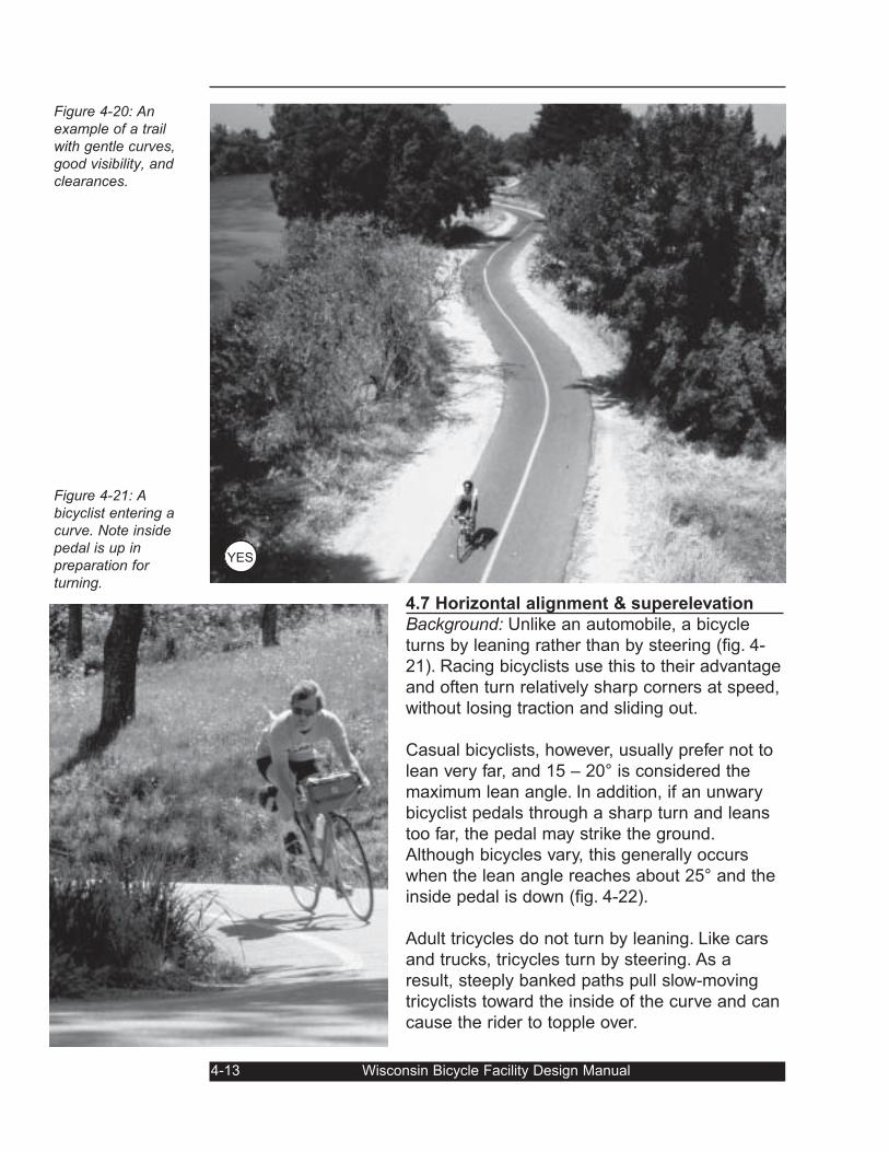
4.7 Horizontal alignment & superelevation
Background: Unlike an automobile, a bicycle
turns by leaning rather than by steering (fig. 4-
21). Racing bicyclists use this to their advantage
and often turn relatively sharp corners at speed,
without losing traction and sliding out.
Casual bicyclists, however, usually prefer not to
lean very far, and 15 – 20° is considered the
maximum lean angle. In addition, if an unwary
bicyclist pedals through a sharp turn and leans
too far, the pedal may strike the ground.
Although bicycles vary, this generally occurs
when the lean angle reaches about 25° and the
inside pedal is down (fig. 4-22).
Adult tricycles do not turn by leaning. Like cars
and trucks, tricycles turn by steering. As a
result, steeply banked paths pull slow-moving
tricyclists toward the inside of the curve and can
cause the rider to topple over.
4-13 Wisconsin Bicycle Facility Design Manual
Figure 4-20: Anexample of a trailwith gentle curves,good visibility, andclearances.
Figure 4-21: Abicyclist entering acurve. Note insidepedal is up inpreparation forturning.
YES
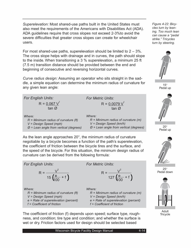
Superelevation: Most shared-use paths built in the United States must
also meet the requirements of the Americans with Disabilities Act (ADA).
ADA guidelines require that cross slopes not exceed 2-3%to avoid the
severe difficulties that greater cross slopes can create for wheelchair
users.
For most shared-use paths, superelevation should be limited to 2 – 3%.
The cross slope helps with drainage and in curves, the path should slope
to the inside. When transitioning a 3 % superelevation, a minimum 25 ft
(7.5 m) transition distance should be provided between the end and
beginning of consecutive and reversing horizontal curves.
Curve radius design: Assuming an operator who sits straight in the sad-
dle, a simple equation can determine the minimum radius of curvature for
any given lean angle:
As the lean angle approaches 20°, the minimum radius of curvature
negotiable by a bicycle becomes a function of the path’s superelevation,
the coefficient of friction between the bicycle tires and the surface, and
the speed of the bicycle. For this situation, the minimum design radius of
curvature can be derived from the following formula:
The coefficient of friction (f) depends upon speed; surface type, rough-
ness, and condition; tire type and condition; and whether the surface is
wet or dry. Friction factors used for design should be selected based
Wisconsin Bicycle Facility Design Manual 4-14
Figure 4-22: Bicy-cles turn by lean-ing. Too much leancan cause a “pedalstrike.” Tricyclesturn by steering.
For English Units:
R = 0.067 V2
tan Ø
Where: R = Minimum radius of curvature (ft)V = Design Speed (mph)Ø = Lean angle from vertical (degrees)
For Metric Units:
R = 0.0079 V2
tan Ø
Where:R = Minimum radius of curvature (m)V = Design Speed (km/h) Ø = Lean angle from vertical (degrees)
For English Units:
2
R = V
15( e + f)100
Where: R = Minimum radius of curvature (ft)V = Design Speed (mph)e = Rate of superelevation (percent)f = Coefficient of friction
For Metric Units:
2
R = V
127( e + f)100
Where:R = Minimum radius of curvature (m)V = Design Speed (km/h) e = Rate of superelevation (percent)f = Coefficient of friction
25°
Pedal down
20°
Pedal up
15°
Pedal up
AdultTricycle
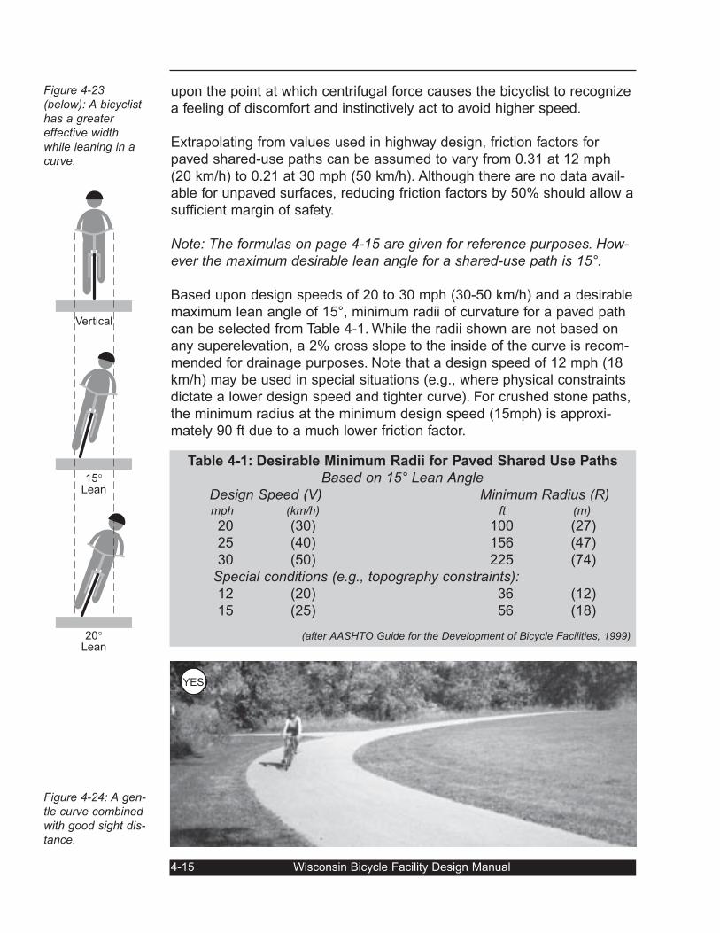
upon the point at which centrifugal force causes the bicyclist to recognize
a feeling of discomfort and instinctively act to avoid higher speed.
Extrapolating from values used in highway design, friction factors for
paved shared-use paths can be assumed to vary from 0.31 at 12 mph
(20 km/h) to 0.21 at 30 mph (50 km/h). Although there are no data avail-
able for unpaved surfaces, reducing friction factors by 50% should allow a
sufficient margin of safety.
Note: The formulas on page 4-15 are given for reference purposes. How-ever the maximum desirable lean angle for a shared-use path is 15°.
Based upon design speeds of 20 to 30 mph (30-50 km/h) and a desirable
maximum lean angle of 15°, minimum radii of curvature for a paved path
can be selected from Table 4-1. While the radii shown are not based on
any superelevation, a 2% cross slope to the inside of the curve is recom-
mended for drainage purposes. Note that a design speed of 12 mph (18
km/h) may be used in special situations (e.g., where physical constraints
dictate a lower design speed and tighter curve). For crushed stone paths,
the minimum radius at the minimum design speed (15mph) is approxi-
mately 90 ft due to a much lower friction factor.
4-15 Wisconsin Bicycle Facility Design Manual
Figure 4-23(below): A bicyclisthas a greatereffective widthwhile leaning in acurve.
Figure 4-24: A gen-tle curve combinedwith good sight dis-tance.
15°
Lean
Vertical
20°
Lean
Table 4-1: Desirable Minimum Radii for Paved Shared Use Paths
Based on 15° Lean AngleDesign Speed (V) Minimum Radius (R)mph (km/h) ft (m)
20 (30) 100 (27)
25 (40) 156 (47)
30 (50) 225 (74)
Special conditions (e.g., topography constraints):12 (20) 36 (12)
15 (25) 56 (18)
(after AASHTO Guide for the Development of Bicycle Facilities, 1999)
YES
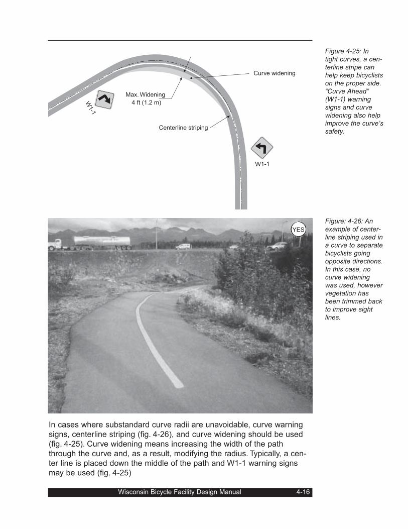
In cases where substandard curve radii are unavoidable, curve warning
signs, centerline striping (fig. 4-26), and curve widening should be used
(fig. 4-25). Curve widening means increasing the width of the path
through the curve and, as a result, modifying the radius. Typically, a cen-
ter line is placed down the middle of the path and W1-1 warning signs
may be used (fig. 4-25)
Wisconsin Bicycle Facility Design Manual 4-16
Figure 4-25: Intight curves, a cen-terline stripe canhelp keep bicyclistson the proper side.“Curve Ahead”(W1-1) warningsigns and curvewidening also helpimprove the curve’ssafety.
Figure: 4-26: Anexample of center-line striping used ina curve to separatebicyclists goingopposite directions.In this case, nocurve wideningwas used, howevervegetation hasbeen trimmed backto improve sightlines.
Curve widening
Centerline striping
W1-1
W1-1
Max. Widening
4 ft (1.2 m)
YES
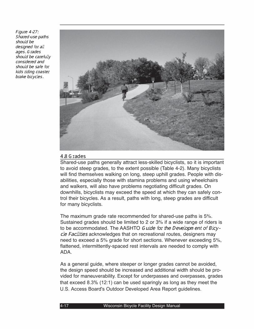
4.8 GradesShared-use paths generally attract less-skilled bicyclists, so it is importantto avoid steep grades, to the extent possible (Table 4-2). Many bicyclistswill find themselves walking on long, steep uphill grades. People with dis-abilities, especially those with stamina problems and using wheelchairsand walkers, will also have problems negotiating difficult grades. Ondownhills, bicyclists may exceed the speed at which they can safely con-trol their bicycles. As a result, paths with long, steep grades are difficultfor many bicyclists. The maximum grade rate recommended for shared-use paths is 5%.Sustained grades should be limited to 2 or 3% if a wide range of riders isto be accommodated. The AASHTO Guide for the Development of Bicy-cle Facilities acknowledges that on recreational routes, designers mayneed to exceed a 5% grade for short sections. Whenever exceeding 5%,flattened, intermittently-spaced rest intervals are needed to comply withADA. As a general guide, where steeper or longer grades cannot be avoided,the design speed should be increased and additional width should be pro-vided for maneuverability. Except for underpasses and overpasses, grades
that exceed 8.3% (12:1) can be used sparingly as long as they meet the
U.S. Access Board's Outdoor Developed Area Report guidelines.
4-17 Wisconsin Bicycle Facility Design Manual
Figure 4-27:Shared-use pathsshould bedesigned for allages. Gradesshould be carefullyconsidered andshould be safe forkids riding coasterbrake bicycles.
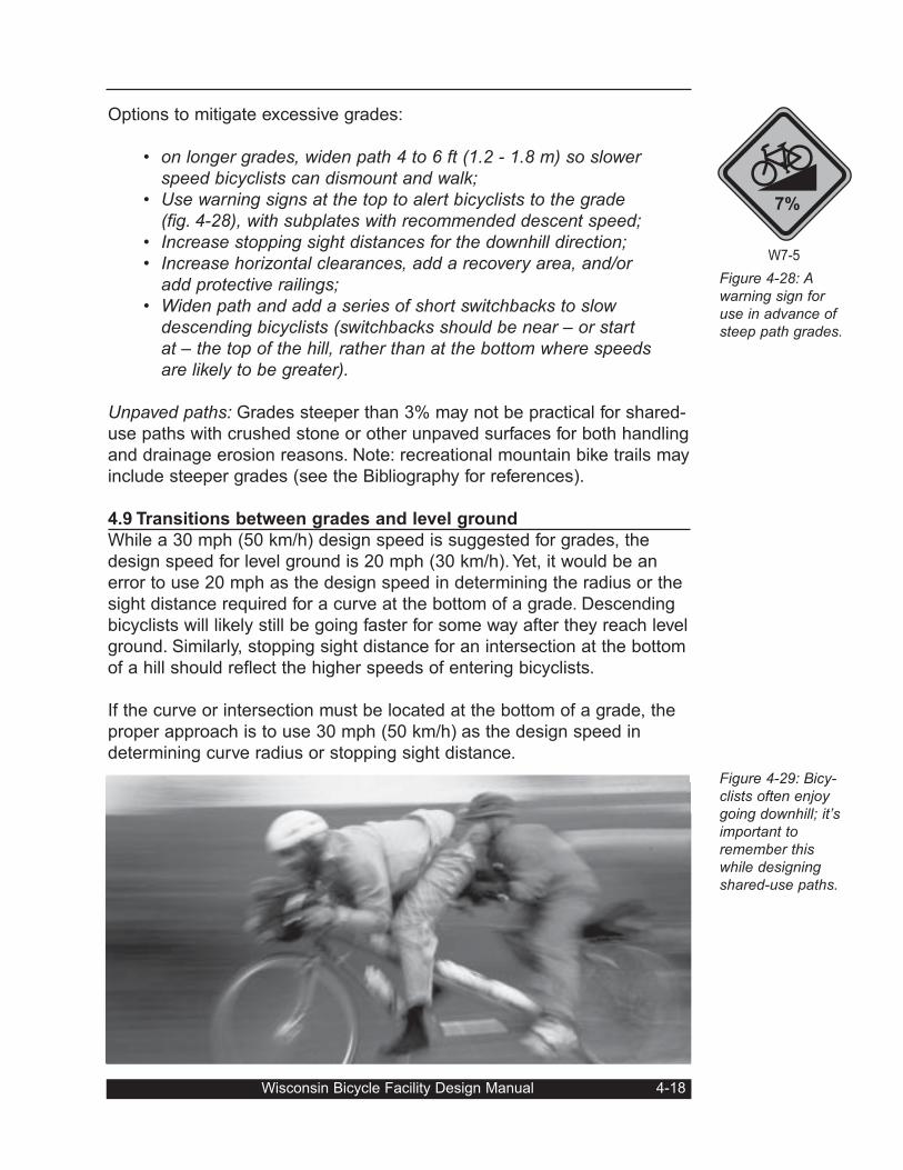
Options to mitigate excessive grades:
• on longer grades, widen path 4 to 6 ft (1.2 - 1.8 m) so slowerspeed bicyclists can dismount and walk;
• Use warning signs at the top to alert bicyclists to the grade(fig. 4-28), with subplates with recommended descent speed;
• Increase stopping sight distances for the downhill direction;• Increase horizontal clearances, add a recovery area, and/or
add protective railings;• Widen path and add a series of short switchbacks to slow
descending bicyclists (switchbacks should be near – or startat – the top of the hill, rather than at the bottom where speedsare likely to be greater).
Unpaved paths: Grades steeper than 3% may not be practical for shared-
use paths with crushed stone or other unpaved surfaces for both handling
and drainage erosion reasons. Note: recreational mountain bike trails may
include steeper grades (see the Bibliography for references).
4.9 Transitions between grades and level ground
While a 30 mph (50 km/h) design speed is suggested for grades, the
design speed for level ground is 20 mph (30 km/h). Yet, it would be an
error to use 20 mph as the design speed in determining the radius or the
sight distance required for a curve at the bottom of a grade. Descending
bicyclists will likely still be going faster for some way after they reach level
ground. Similarly, stopping sight distance for an intersection at the bottom
of a hill should reflect the higher speeds of entering bicyclists.
If the curve or intersection must be located at the bottom of a grade, the
proper approach is to use 30 mph (50 km/h) as the design speed in
determining curve radius or stopping sight distance.
Wisconsin Bicycle Facility Design Manual 4-18
Figure 4-28: Awarning sign foruse in advance ofsteep path grades.
Figure 4-29: Bicy-clists often enjoygoing downhill; it’simportant toremember thiswhile designingshared-use paths.
W7-5
7%
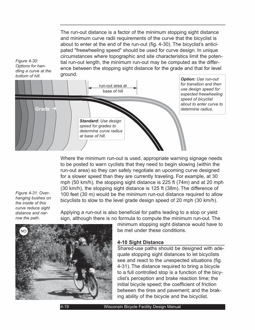
The run-out distance is a factor of the minimum stopping sight distance
and minimum curve radii requirements of the curve that the bicyclist is
about to enter at the end of the run-out (fig. 4-30). The bicyclist’s antici-
pated "freewheeling speed" should be used for curve design. In unique
circumstances where topographic and site characteristics limit the poten-
tial run-out length, the minimum run-out may be computed as the differ-
ence between the stopping sight distance for the grade and that for level
ground.
Where the minimum run-out is used, appropriate warning signage needs
to be posted to warn cyclists that they need to begin slowing (within the
run-out area) so they can safely negotiate an upcoming curve designed
for a slower speed than they are currently traveling. For example, at 30
mph (50 km/h), the stopping sight distance is 225 ft (74m) and at 20 mph
(30 km/h), the stopping sight distance is 125 ft (38m). The difference of
100 feet (30 m) would be the minimum run-out distance required to allow
bicyclists to slow to the level grade design speed of 20 mph (30 km/h).
Applying a run-out is also beneficial for paths leading to a stop or yield
sign, although there is no formula to compute the minimum run-out. The
minimum stopping sight distance would have to
be met under these conditions.
4-10 Sight Distance
Shared-use paths should be designed with ade-
quate stopping sight distances to let bicyclists
see and react to the unexpected situations (fig.
4-31). The distance required to bring a bicycle
to a full controlled stop is a function of the bicy-
clist’s perception and brake reaction time; the
initial bicycle speed; the coefficient of friction
between the tires and pavement; and the brak-
ing ability of the bicycle and the bicyclist.
4-19 Wisconsin Bicycle Facility Design Manual
Figure 4-30:Options for han-dling a curve at thebottom of hill.
Figure 4-31: Over-hanging bushes onthe inside of thiscurve reduce sightdistance and nar-row the path.
run-out area at
base of hill
Option: Use run-outfor transition and thenuse design speed forexpected freewheelingspeed of bicyclistabout to enter curve todetermine radius. Grade ➞
Standard: Use designspeed for grades todetermine curve radiusat base of hill.
NO
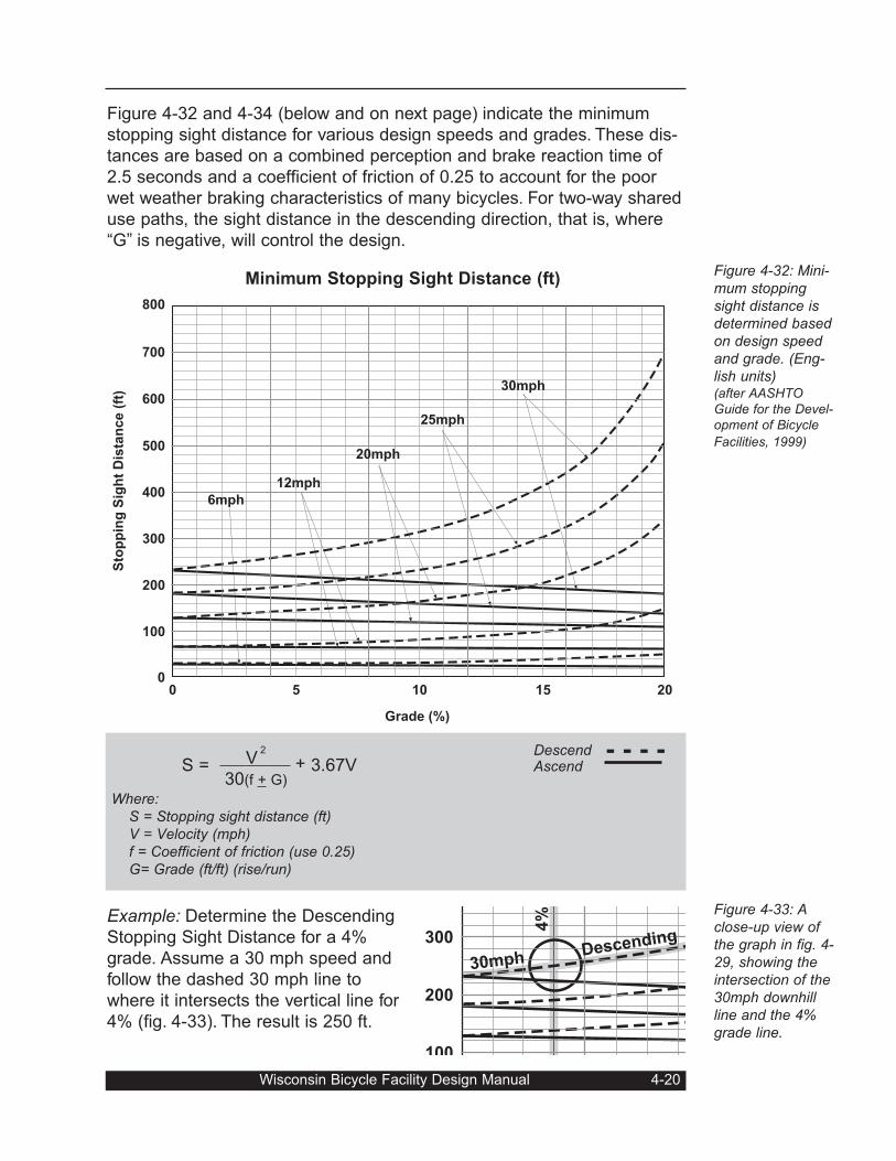
Figure 4-32 and 4-34 (below and on next page) indicate the minimum
stopping sight distance for various design speeds and grades. These dis-
tances are based on a combined perception and brake reaction time of
2.5 seconds and a coefficient of friction of 0.25 to account for the poor
wet weather braking characteristics of many bicycles. For two-way shared
use paths, the sight distance in the descending direction, that is, where
“G” is negative, will control the design.
Example: Determine the Descending
Stopping Sight Distance for a 4%
grade. Assume a 30 mph speed and
follow the dashed 30 mph line to
where it intersects the vertical line for
4% (fig. 4-33). The result is 250 ft.
Wisconsin Bicycle Facility Design Manual 4-20
Figure 4-32: Mini-mum stoppingsight distance isdetermined basedon design speedand grade. (Eng-lish units)(after AASHTOGuide for the Devel-opment of Bicycle
Facilities, 1999)
Figure 4-33: Aclose-up view ofthe graph in fig. 4-29, showing theintersection of the30mph downhillline and the 4%grade line.
700
600
800
500
400
300
200
100
0 5 10 15 20
Grade (%)
Sto
pp
ing
Sig
ht
Dis
tan
ce
(ft
)
0
6mph
12mph
20mph
25mph
30mph
2
S = V + 3.67V30(f + G)
Where:S = Stopping sight distance (ft)V = Velocity (mph) f = Coefficient of friction (use 0.25)G= Grade (ft/ft) (rise/run)
Descend - - - -Ascend
Minimum Stopping Sight Distance (ft)
300
200
100
4%
30mphDescending
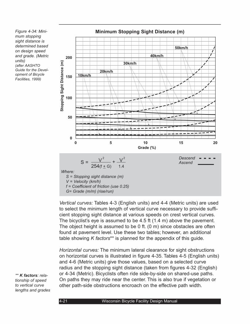
Vertical curves: Tables 4-3 (English units) and 4-4 (Metric units) are used
to select the minimum length of vertical curve necessary to provide suffi-
cient stopping sight distance at various speeds on crest vertical curves.
The bicyclist’s eye is assumed to be 4.5 ft (1.4 m) above the pavement.
The object height is assumed to be 0 ft. (0 m) since obstacles are often
found at pavement level. Use these two tables; however, an additional
table showing K factors** is planned for the appendix of this guide.
Horizontal curves: The minimum lateral clearance for sight obstructions
on horizontal curves is illustrated in figure 4-35. Tables 4-5 (English units)
and 4-6 (Metric units) give those values, based on a selected curve
radius and the stopping sight distance (taken from figures 4-32 (English)
or 4-34 (Metric). Bicyclists often ride side-by-side on shared-use paths.
On paths they may ride near the center. This is also true if vegetation or
other path-side obstructions encroach on the effective path width.
4-21 Wisconsin Bicycle Facility Design Manual
Figure 4-34: Mini-mum stoppingsight distance isdetermined basedon design speedand grade. (Metricunits)(after AASHTOGuide for the Devel-opment of Bicycle
Facilities, 1999)
** K factors: rela-tionship of speedto vertical curvelengths and grades
2 2
S = V + V
254(f + G) 1.4
Where:S = Stopping sight distance (m)V = Velocity (km/h) f = Coefficient of friction (use 0.25)G= Grade (m/m) (rise/run)
Descend - - - -Ascend
10km/h20km/h
30km/h
40km/h
50km/h
200S
top
pin
g S
igh
t D
ista
nc
e (
m)
150
100
50
0
0 5 10 15 20
Grade (%)
Minimum Stopping Sight Distance (m)
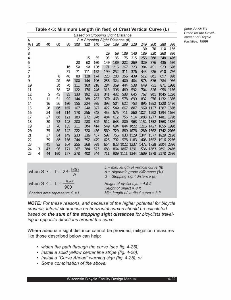
NOTE: For these reasons, and because of the higher potential for bicyclecrashes, lateral clearances on horizontal curves should be calculatedbased on the sum of the stopping sight distances for bicyclists travel-ing in opposite directions around the curve.
Where adequate sight distance cannot be provided, mitigation measures
like those described below can help:
• widen the path through the curve (see fig. 4-25);• Install a solid yellow center line stripe (fig. 4-26);• Install a “Curve Ahead” warning sign (fig. 4-25); or • Some combination of the above.
Table 4-3: Minimum Length (in feet) of Crest Vertical Curve (L)
Based on Stopping Sight DistanceA S = Stopping Sight Distance (ft)(%) 20 40 60 80 100 120 140 160 180 200 220 240 260 280 3002 30 70 110 1503 20 60 100 140 180 220 260 3004 15 55 95 135 175 215 256 300 348 4005 20 60 100 140 180 222 269 320 376 436 5006 10 50 90 130 171 216 267 323 384 451 523 6007 31 71 111 152 199 252 311 376 448 526 610 7008 8 48 88 128 174 228 288 356 430 512 601 697 8009 20 60 100 144 196 256 324 400 484 576 676 784 90010 30 70 111 160 218 284 360 444 538 640 751 871 100011 38 78 122 176 240 313 396 489 592 704 826 958 110012 5 45 85 133 192 261 341 432 533 645 768 901 1045 120013 11 51 92 144 208 283 370 468 578 699 832 976 1132 130014 16 56 100 156 224 305 398 504 622 753 896 1052 1220 140015 20 60 107 167 240 327 427 540 667 807 960 1127 1307 150016 24 64 114 178 256 348 455 576 711 860 1024 1202 1394 160017 27 68 121 189 272 370 484 612 756 914 1088 1277 1481 170018 30 72 128 200 288 392 512 648 800 968 1152 1352 1568 180019 33 76 135 211 304 414 540 684 844 1022 1216 1427 1655 190020 35 80 142 222 320 436 569 720 889 1076 1280 1502 1742 200021 37 84 149 233 336 457 597 756 933 1129 1344 1577 1829 210022 39 88 156 244 352 479 626 792 978 1183 1408 1652 1916 220023 41 92 164 256 368 501 654 828 1022 1237 1472 1728 2004 230024 3 43 96 171 267 384 523 683 864 1067 1291 1536 1803 2091 240025 4 44 100 177 278 400 544 711 900 1111 1344 1600 1878 2178 2500
when S > L L = 2S- 900A
2when S < L L = AS
900
Shaded area represents S = L
L = Min. length of vertical curve (ft)A = Algebraic grade difference (%)S = Stopping sight distance (ft)
Height of cyclist eye = 4.5 ftHeight of object = 0 ftMin. length of vertical curve = 3 ft
Wisconsin Bicycle Facility Design Manual 4-22
(after AASHTOGuide for the Devel-opment of Bicycle
Facilities, 1999)
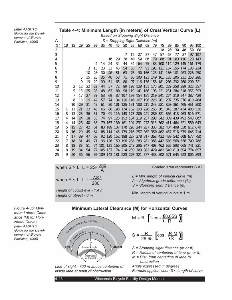
4-23 Wisconsin Bicycle Facility Design Manual
Figure 4-35: Mini-mum Lateral Clear-ance (M) for Hori-zontal Curves(after AASHTOGuide for the Devel-opment of Bicycle
Facilities, 1999)
(after AASHTOGuide for the Devel-opment of Bicycle
Facilities, 1999)
Line of sight - 700 m above centerline ofinside lane at point of obstruction
M = R [ 1-cos(28.65S)]R
S = R [ cos-1(R-M)]28.65 R
S = Stopping sight distance (m or ft)R = Radius of centerline of lane (m or ft)M = Dist. from centerline of lane to
obstructionAngle expressed in degreesFormula applies when S ≤ length of curve
insi
delane
Eye Line of sight
“S” m
easured along this line
m
Object
Obstructionor Cutbank
A S = Stopping Sight Distance (m)(%) 10 15 20 25 30 35 40 45 50 55 60 65 70 75 80 85 90 95 1002 10 20 30 40 50 603 7 17 27 37 47 57 67 77 87 97 1074 10 20 30 40 50 60 70 80 91 103 116 129 1435 4 14 24 34 44 54 64 75 88 100 114 129 145 161 1796 3 13 23 33 43 54 65 77 91 105 121 137 155 174 193 2147 10 20 30 40 51 63 76 90 106 123 141 160 181 203 226 2508 5 15 25 35 46 58 71 86 103 121 140 161 183 206 231 258 2869 9 19 29 39 51 65 80 97 116 136 158 181 206 232 260 290 32110 2 12 22 32 44 57 72 89 108 129 151 175 201 229 258 289 322 35711 5 15 25 35 48 63 80 98 119 141 166 193 221 251 284 318 355 39312 7 17 27 39 53 69 87 107 130 154 181 210 241 274 310 347 387 42913 8 18 29 42 57 74 94 116 140 167 196 228 261 297 335 376 419 46414 10 20 31 45 61 80 101 125 151 180 211 245 281 320 361 405 451 50015 1 11 21 33 48 66 86 108 134 162 193 226 263 301 343 387 434 483 53616 3 13 23 36 51 70 91 116 143 173 206 241 280 321 366 413 463 516 57117 4 14 24 38 55 74 97 123 152 184 219 257 298 342 389 439 492 548 60718 4 14 26 40 58 79 103 130 161 194 231 272 315 362 411 464 521 580 64319 5 15 27 42 61 83 109 137 170 205 244 287 333 382 434 490 550 612 67920 6 16 29 45 64 88 114 145 179 216 257 302 350 402 457 516 579 645 71421 7 17 30 47 68 92 120 152 188 227 270 317 368 422 480 542 608 677 75022 7 18 31 49 71 96 126 159 196 238 283 281 385 442 503 568 636 709 78623 8 18 33 51 74 101 131 166 205 248 296 347 403 462 526 593 665 741 82124 8 19 34 54 77 105 137 174 214 259 309 362 420 482 549 619 694 774 85725 9 20 36 56 80 109 143 181 223 270 321 377 438 502 571 645 723 806 893when S > L L = 2S- 280
A
2when S < L L = AS
280
Height of cyclist eye - 1.4 m
Height of object - 0 m
Shaded area represents S = L
L = Min. length of vertical curve (m)A = Algebraic grade difference (%)S = Stopping sight distance (m)
Min. length of vertical curve = 1 m
Table 4-4: Minimum Length (in meters) of Crest Vertical Curve (L)Based on Stopping Sight Distance
Minimum Lateral Clearance (M) for Horizontal Curves
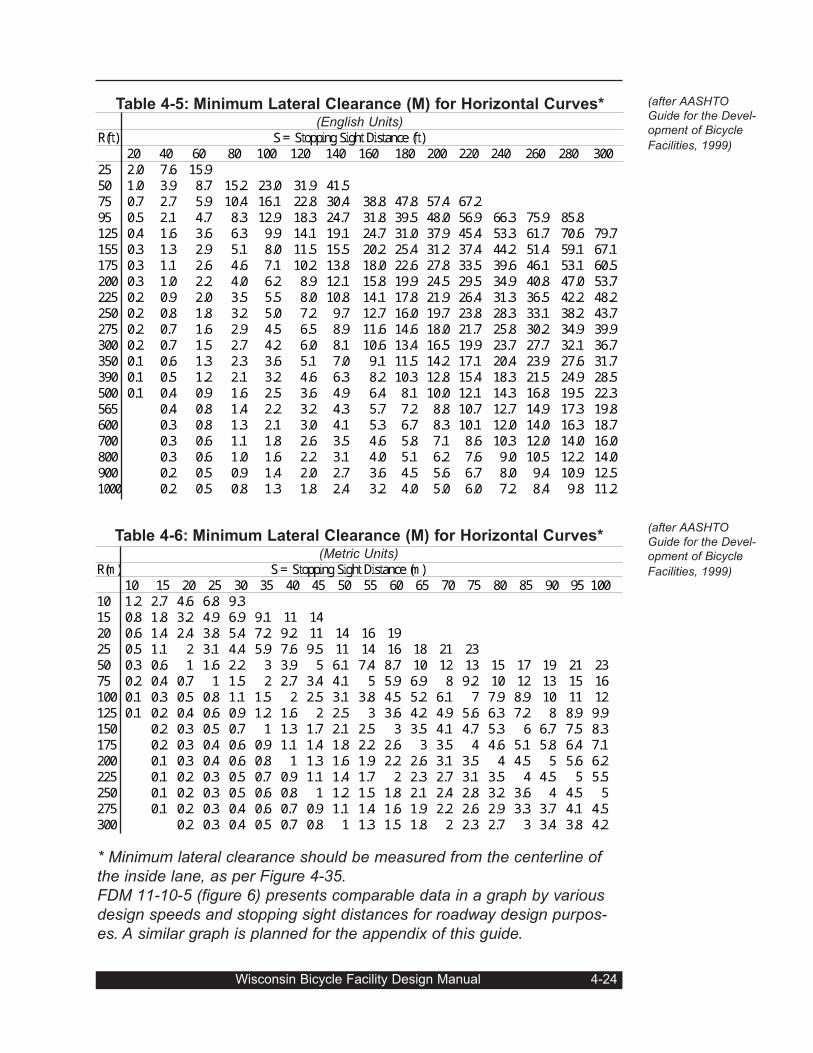
* Minimum lateral clearance should be measured from the centerline ofthe inside lane, as per Figure 4-35.FDM 11-10-5 (figure 6) presents comparable data in a graph by variousdesign speeds and stopping sight distances for roadway design purpos-es. A similar graph is planned for the appendix of this guide.
Wisconsin Bicycle Facility Design Manual 4-24
(after AASHTOGuide for the Devel-opment of Bicycle
Facilities, 1999)
(after AASHTOGuide for the Devel-opment of Bicycle
Facilities, 1999)
Table 4-5: Minimum Lateral Clearance (M) for Horizontal Curves* (English Units)R(ft) S = Stopping Sight Distance (ft)20 40 60 80 100 120 140 160 180 200 220 240 260 280 30025 2.0 7.6 15.950 1.0 3.9 8.7 15.2 23.0 31.9 41.575 0.7 2.7 5.9 10.4 16.1 22.8 30.4 38.8 47.8 57.4 67.295 0.5 2.1 4.7 8.3 12.9 18.3 24.7 31.8 39.5 48.0 56.9 66.3 75.9 85.8125 0.4 1.6 3.6 6.3 9.9 14.1 19.1 24.7 31.0 37.9 45.4 53.3 61.7 70.6 79.7155 0.3 1.3 2.9 5.1 8.0 11.5 15.5 20.2 25.4 31.2 37.4 44.2 51.4 59.1 67.1175 0.3 1.1 2.6 4.6 7.1 10.2 13.8 18.0 22.6 27.8 33.5 39.6 46.1 53.1 60.5200 0.3 1.0 2.2 4.0 6.2 8.9 12.1 15.8 19.9 24.5 29.5 34.9 40.8 47.0 53.7225 0.2 0.9 2.0 3.5 5.5 8.0 10.8 14.1 17.8 21.9 26.4 31.3 36.5 42.2 48.2250 0.2 0.8 1.8 3.2 5.0 7.2 9.7 12.7 16.0 19.7 23.8 28.3 33.1 38.2 43.7275 0.2 0.7 1.6 2.9 4.5 6.5 8.9 11.6 14.6 18.0 21.7 25.8 30.2 34.9 39.9300 0.2 0.7 1.5 2.7 4.2 6.0 8.1 10.6 13.4 16.5 19.9 23.7 27.7 32.1 36.7350 0.1 0.6 1.3 2.3 3.6 5.1 7.0 9.1 11.5 14.2 17.1 20.4 23.9 27.6 31.7390 0.1 0.5 1.2 2.1 3.2 4.6 6.3 8.2 10.3 12.8 15.4 18.3 21.5 24.9 28.5500 0.1 0.4 0.9 1.6 2.5 3.6 4.9 6.4 8.1 10.0 12.1 14.3 16.8 19.5 22.3565 0.4 0.8 1.4 2.2 3.2 4.3 5.7 7.2 8.8 10.7 12.7 14.9 17.3 19.8600 0.3 0.8 1.3 2.1 3.0 4.1 5.3 6.7 8.3 10.1 12.0 14.0 16.3 18.7700 0.3 0.6 1.1 1.8 2.6 3.5 4.6 5.8 7.1 8.6 10.3 12.0 14.0 16.0800 0.3 0.6 1.0 1.6 2.2 3.1 4.0 5.1 6.2 7.6 9.0 10.5 12.2 14.0900 0.2 0.5 0.9 1.4 2.0 2.7 3.6 4.5 5.6 6.7 8.0 9.4 10.9 12.51000 0.2 0.5 0.8 1.3 1.8 2.4 3.2 4.0 5.0 6.0 7.2 8.4 9.8 11.2
Table 4-6: Minimum Lateral Clearance (M) for Horizontal Curves*(Metric Units)R(m) S = Stopping Sight Distance (m)10 15 20 25 30 35 40 45 50 55 60 65 70 75 80 85 90 95 10010 1.2 2.7 4.6 6.8 9.315 0.8 1.8 3.2 4.9 6.9 9.1 11 1420 0.6 1.4 2.4 3.8 5.4 7.2 9.2 11 14 16 1925 0.5 1.1 2 3.1 4.4 5.9 7.6 9.5 11 14 16 18 21 2350 0.3 0.6 1 1.6 2.2 3 3.9 5 6.1 7.4 8.7 10 12 13 15 17 19 21 2375 0.2 0.4 0.7 1 1.5 2 2.7 3.4 4.1 5 5.9 6.9 8 9.2 10 12 13 15 16100 0.1 0.3 0.5 0.8 1.1 1.5 2 2.5 3.1 3.8 4.5 5.2 6.1 7 7.9 8.9 10 11 12125 0.1 0.2 0.4 0.6 0.9 1.2 1.6 2 2.5 3 3.6 4.2 4.9 5.6 6.3 7.2 8 8.9 9.9150 0.2 0.3 0.5 0.7 1 1.3 1.7 2.1 2.5 3 3.5 4.1 4.7 5.3 6 6.7 7.5 8.3175 0.2 0.3 0.4 0.6 0.9 1.1 1.4 1.8 2.2 2.6 3 3.5 4 4.6 5.1 5.8 6.4 7.1200 0.1 0.3 0.4 0.6 0.8 1 1.3 1.6 1.9 2.2 2.6 3.1 3.5 4 4.5 5 5.6 6.2225 0.1 0.2 0.3 0.5 0.7 0.9 1.1 1.4 1.7 2 2.3 2.7 3.1 3.5 4 4.5 5 5.5250 0.1 0.2 0.3 0.5 0.6 0.8 1 1.2 1.5 1.8 2.1 2.4 2.8 3.2 3.6 4 4.5 5275 0.1 0.2 0.3 0.4 0.6 0.7 0.9 1.1 1.4 1.6 1.9 2.2 2.6 2.9 3.3 3.7 4.1 4.5300 0.2 0.3 0.4 0.5 0.7 0.8 1 1.3 1.5 1.8 2 2.3 2.7 3 3.4 3.8 4.2
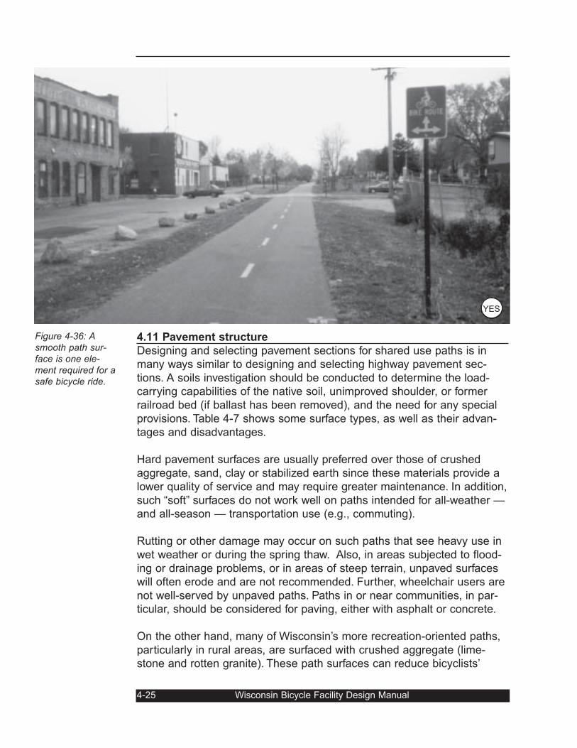
4.11 Pavement structure
Designing and selecting pavement sections for shared use paths is in
many ways similar to designing and selecting highway pavement sec-
tions. A soils investigation should be conducted to determine the load-
carrying capabilities of the native soil, unimproved shoulder, or former
railroad bed (if ballast has been removed), and the need for any special
provisions. Table 4-7 shows some surface types, as well as their advan-
tages and disadvantages.
Hard pavement surfaces are usually preferred over those of crushed
aggregate, sand, clay or stabilized earth since these materials provide a
lower quality of service and may require greater maintenance. In addition,
such “soft” surfaces do not work well on paths intended for all-weather —
and all-season — transportation use (e.g., commuting).
Rutting or other damage may occur on such paths that see heavy use in
wet weather or during the spring thaw. Also, in areas subjected to flood-
ing or drainage problems, or in areas of steep terrain, unpaved surfaces
will often erode and are not recommended. Further, wheelchair users are
not well-served by unpaved paths. Paths in or near communities, in par-
ticular, should be considered for paving, either with asphalt or concrete.
On the other hand, many of Wisconsin’s more recreation-oriented paths,
particularly in rural areas, are surfaced with crushed aggregate (lime-
stone and rotten granite). These path surfaces can reduce bicyclists’
4-25 Wisconsin Bicycle Facility Design Manual
Figure 4-36: Asmooth path sur-face is one ele-ment required for asafe bicycle ride.
YES
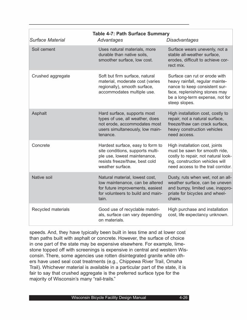
speeds. And, they have typically been built in less time and at lower cost
than paths built with asphalt or concrete. However, the surface of choice
in one part of the state may be expensive elsewhere. For example, lime-
stone topped off with screenings is expensive in central and western Wis-
consin. There, some agencies use rotten disintegrated granite while oth-
ers have used seal coat treatments (e.g., Chippewa River Trail, Omaha
Trail). Whichever material is available in a particular part of the state, it is
fair to say that crushed aggregate is the preferred surface type for the
majority of Wisconsin’s many “rail-trails.”
Wisconsin Bicycle Facility Design Manual 4-26
Soil cement
Crushed aggregate
Asphalt
Concrete
Native soil
Recycled materials
Uses natural materials, more
durable than native soils,
smoother surface, low cost.
Soft but firm surface, natural
material, moderate cost (varies
regionally), smooth surface,
accommodates multiple use.
Hard surface, supports most
types of use, all weather, does
not erode, accommodates most
users simultaneously, low main-
tenance.
Hardest surface, easy to form to
site conditions, supports multi-
ple use, lowest maintenance,
resists freeze/thaw, best cold
weather surface.
Natural material, lowest cost,
low maintenance, can be altered
for future improvements, easiest
for volunteers to build and main-
tain.
Good use of recyclable materi-
als, surface can vary depending
on materials.
Surface wears unevenly, not a
stable all-weather surface,
erodes, difficult to achieve cor-
rect mix.
Surface can rut or erode with
heavy rainfall, regular mainte-
nance to keep consistent sur-
face, replenishing stones may
be a long-term expense, not for
steep slopes.
High installation cost, costly to
repair, not a natural surface,
freeze/thaw can crack surface,
heavy construction vehicles
need access.
High installation cost, joints
must be sawn for smooth ride,
costly to repair, not natural look-
ing, construction vehicles will
need access to the trail corridor.
Dusty, ruts when wet, not an all-
weather surface, can be uneven
and bumpy, limited use, inappro-
priate for bicycles and wheel-
chairs.
High purchase and installation
cost, life expectancy unknown.
Table 4-7: Path Surface Summary
Surface Material Advantages Disadvantages
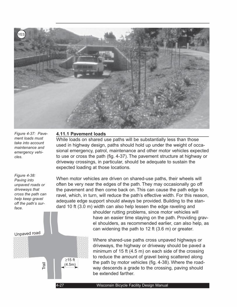
4.11.1 Pavement loads
While loads on shared use paths will be substantially less than those
used in highway design, paths should hold up under the weight of occa-
sional emergency, patrol, maintenance and other motor vehicles expected
to use or cross the path (fig. 4-37). The pavement structure at highway or
driveway crossings, in particular, should be adequate to sustain the
expected loading at those locations.
When motor vehicles are driven on shared-use paths, their wheels will
often be very near the edges of the path. They may occasionally go off
the pavement and then come back on. This can cause the path edge to
ravel, which, in turn, will reduce the path’s effective width. For this reason,
adequate edge support should always be provided. Building to the stan-
dard 10 ft (3.0 m) width can also help lessen the edge raveling and
shoulder rutting problems, since motor vehicles will
have an easier time staying on the path. Providing grav-
el shoulders, as recommended earlier, can also help, as
can widening the path to 12 ft (3.6 m) or greater.
Where shared-use paths cross unpaved highways or
driveways, the highway or driveway should be paved a
minimum of 15 ft (4.5 m) on each side of the crossing
to reduce the amount of gravel being scattered along
the path by motor vehicles (fig. 4-38). Where the road-
way descends a grade to the crossing, paving should
be extended farther.
4-27 Wisconsin Bicycle Facility Design Manual
Figure 4-37: Pave-ment loads musttake into accountmaintenance andemergency vehi-cles.
Figure 4-38:Paving intounpaved roads ordriveways thatcross the path canhelp keep graveloff the path’s sur-face.
Tra
il
Unpaved road
≥15 ft
(4.5m)
YES
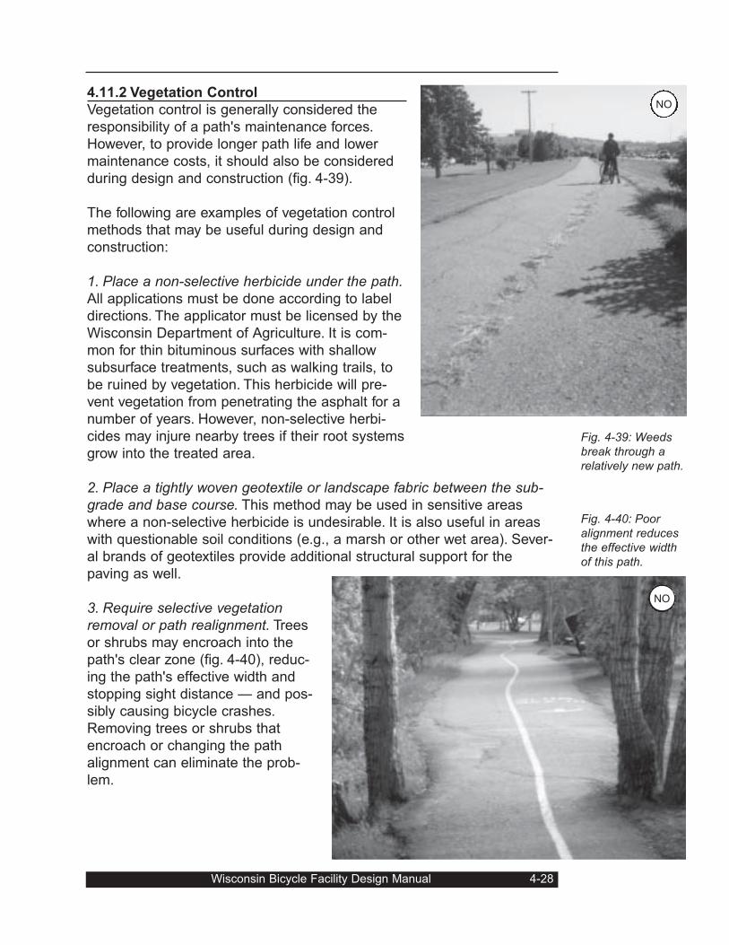
4.11.2 Vegetation Control
Vegetation control is generally considered the
responsibility of a path's maintenance forces.
However, to provide longer path life and lower
maintenance costs, it should also be considered
during design and construction (fig. 4-39).
The following are examples of vegetation control
methods that may be useful during design and
construction:
1. Place a non-selective herbicide under the path.All applications must be done according to label
directions. The applicator must be licensed by the
Wisconsin Department of Agriculture. It is com-
mon for thin bituminous surfaces with shallow
subsurface treatments, such as walking trails, to
be ruined by vegetation. This herbicide will pre-
vent vegetation from penetrating the asphalt for a
number of years. However, non-selective herbi-
cides may injure nearby trees if their root systems
grow into the treated area.
2. Place a tightly woven geotextile or landscape fabric between the sub-grade and base course. This method may be used in sensitive areas
where a non-selective herbicide is undesirable. It is also useful in areas
with questionable soil conditions (e.g., a marsh or other wet area). Sever-
al brands of geotextiles provide additional structural support for the
paving as well.
3. Require selective vegetationremoval or path realignment. Trees
or shrubs may encroach into the
path's clear zone (fig. 4-40), reduc-
ing the path's effective width and
stopping sight distance — and pos-
sibly causing bicycle crashes.
Removing trees or shrubs that
encroach or changing the path
alignment can eliminate the prob-
lem.
Wisconsin Bicycle Facility Design Manual 4-28
Fig. 4-39: Weedsbreak through arelatively new path.
Fig. 4-40: Pooralignment reducesthe effective widthof this path.
NO
NO
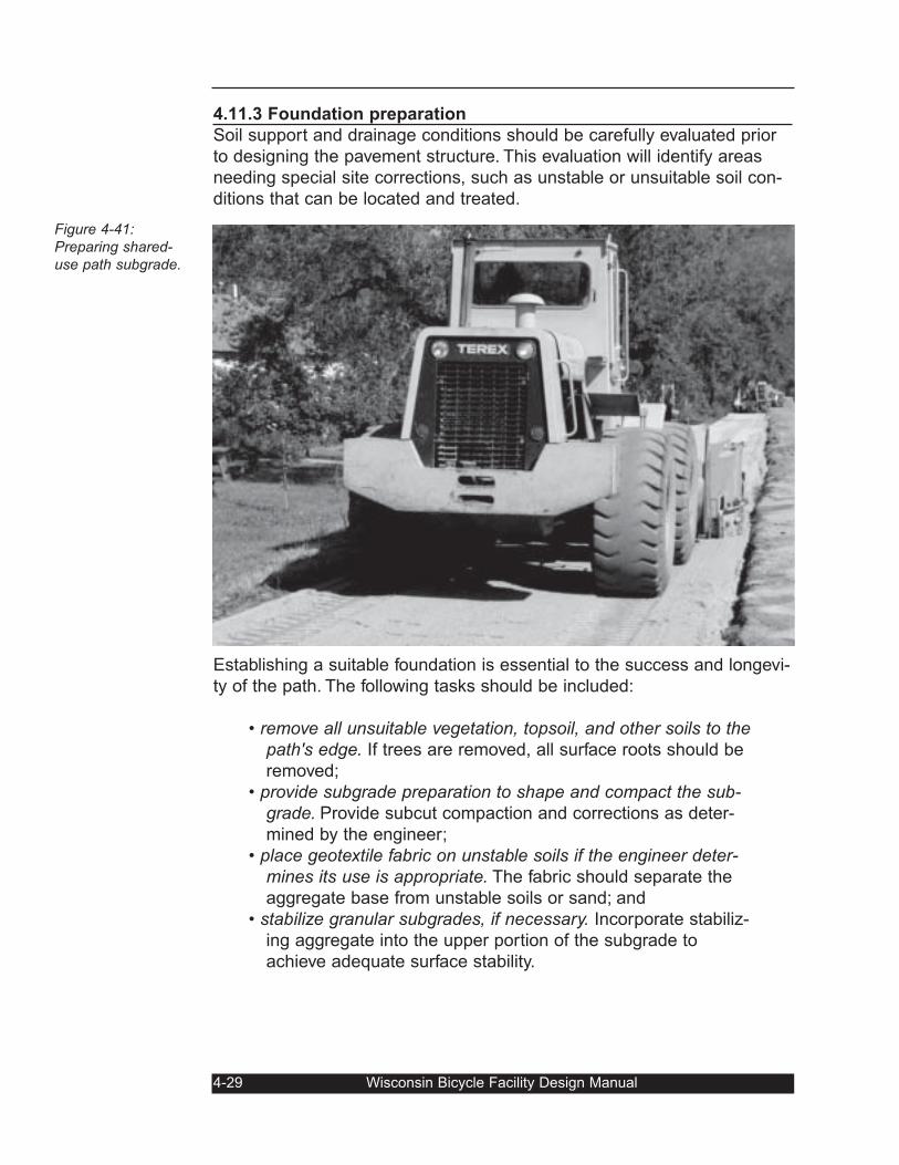
4.11.3 Foundation preparation
Soil support and drainage conditions should be carefully evaluated prior
to designing the pavement structure. This evaluation will identify areas
needing special site corrections, such as unstable or unsuitable soil con-
ditions that can be located and treated.
Establishing a suitable foundation is essential to the success and longevi-
ty of the path. The following tasks should be included:
• remove all unsuitable vegetation, topsoil, and other soils to thepath's edge. If trees are removed, all surface roots should be
removed;
• provide subgrade preparation to shape and compact the sub-grade. Provide subcut compaction and corrections as deter-
mined by the engineer;
• place geotextile fabric on unstable soils if the engineer deter-mines its use is appropriate. The fabric should separate the
aggregate base from unstable soils or sand; and
• stabilize granular subgrades, if necessary. Incorporate stabiliz-
ing aggregate into the upper portion of the subgrade to
achieve adequate surface stability.
4-29 Wisconsin Bicycle Facility Design Manual
Figure 4-41:Preparing shared-use path subgrade.
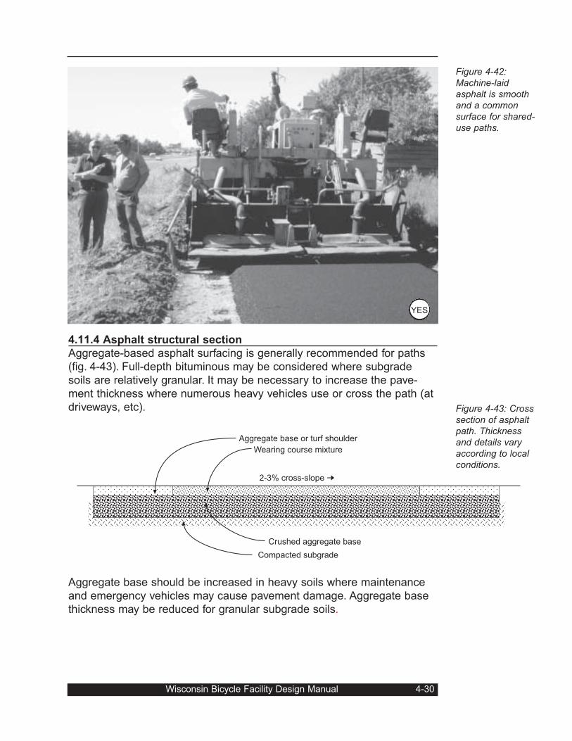
4.11.4 Asphalt structural section
Aggregate-based asphalt surfacing is generally recommended for paths
(fig. 4-43). Full-depth bituminous may be considered where subgrade
soils are relatively granular. It may be necessary to increase the pave-
ment thickness where numerous heavy vehicles use or cross the path (at
driveways, etc).
Aggregate base should be increased in heavy soils where maintenance
and emergency vehicles may cause pavement damage. Aggregate base
thickness may be reduced for granular subgrade soils.
Wisconsin Bicycle Facility Design Manual 4-30
Aggregate base or turf shoulder
Wearing course mixture
Crushed aggregate base
Compacted subgrade
2-3% cross-slope ➞
Figure 4-42:Machine-laidasphalt is smoothand a commonsurface for shared-use paths.
Figure 4-43: Crosssection of asphaltpath. Thicknessand details varyaccording to localconditions.
YES
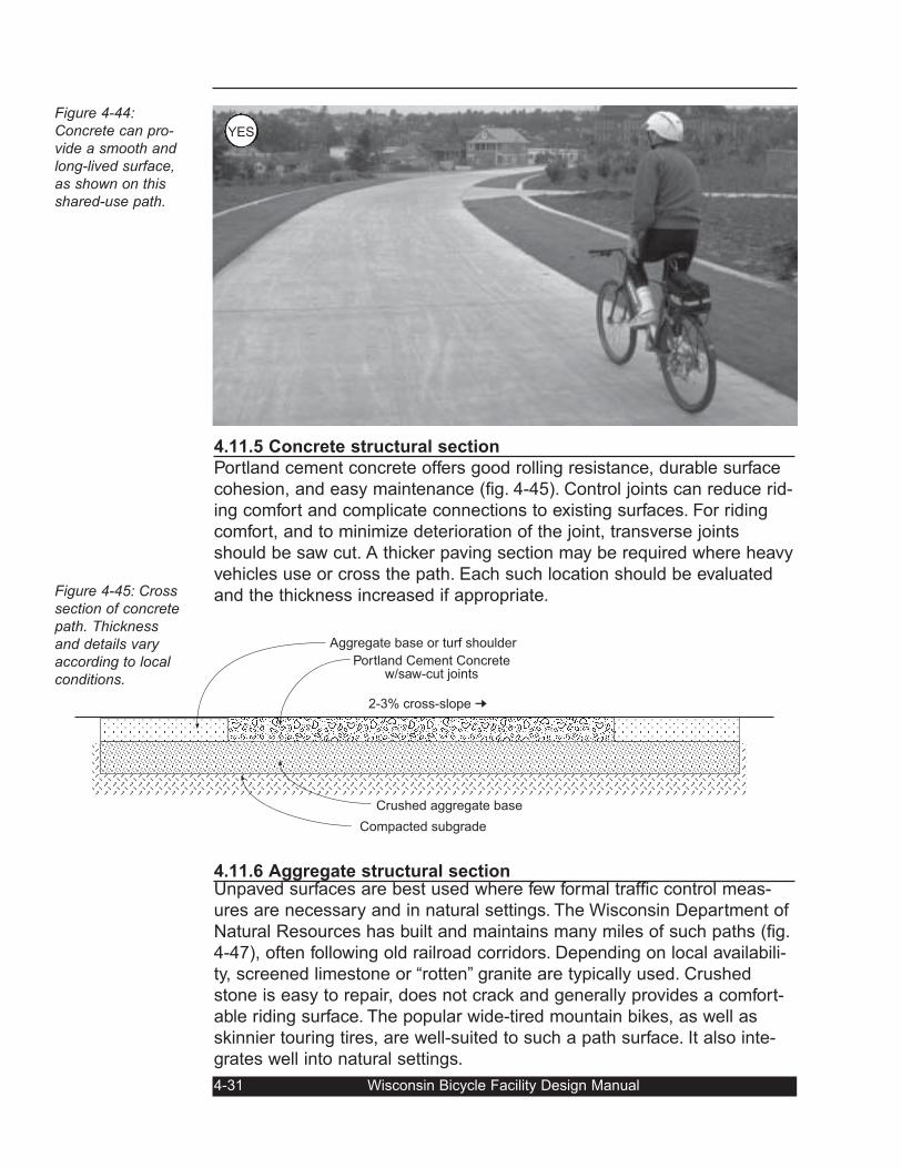
4.11.5 Concrete structural section
Portland cement concrete offers good rolling resistance, durable surface
cohesion, and easy maintenance (fig. 4-45). Control joints can reduce rid-
ing comfort and complicate connections to existing surfaces. For riding
comfort, and to minimize deterioration of the joint, transverse joints
should be saw cut. A thicker paving section may be required where heavy
vehicles use or cross the path. Each such location should be evaluated
and the thickness increased if appropriate.
4.11.6 Aggregate structural sectionUnpaved surfaces are best used where few formal traffic control meas-
ures are necessary and in natural settings. The Wisconsin Department of
Natural Resources has built and maintains many miles of such paths (fig.
4-47), often following old railroad corridors. Depending on local availabili-
ty, screened limestone or “rotten” granite are typically used. Crushed
stone is easy to repair, does not crack and generally provides a comfort-
able riding surface. The popular wide-tired mountain bikes, as well as
skinnier touring tires, are well-suited to such a path surface. It also inte-
grates well into natural settings.
4-31 Wisconsin Bicycle Facility Design Manual
Aggregate base or turf shoulder
Portland Cement Concretew/saw-cut joints
Crushed aggregate base
Compacted subgrade
2-3% cross-slope ➞
Figure 4-44: Concrete can pro-vide a smooth andlong-lived surface,as shown on thisshared-use path.
Figure 4-45: Crosssection of concretepath. Thicknessand details varyaccording to localconditions.
YES
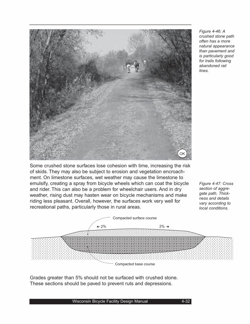
Some crushed stone surfaces lose cohesion with time, increasing the risk
of skids. They may also be subject to erosion and vegetation encroach-
ment. On limestone surfaces, wet weather may cause the limestone to
emulsify, creating a spray from bicycle wheels which can coat the bicycle
and rider. This can also be a problem for wheelchair users. And in dry
weather, rising dust may hasten wear on bicycle mechanisms and make
riding less pleasant. Overall, however, the surfaces work very well for
recreational paths, particularly those in rural areas.
Grades greater than 5% should not be surfaced with crushed stone.
These sections should be paved to prevent ruts and depressions.
Wisconsin Bicycle Facility Design Manual 4-32
Compacted surface course
Compacted base course
2% ➞2%
➞
OK
Figure 4-46: Acrushed stone pathoften has a morenatural appearancethan pavement andis particularly goodfor trails followingabandoned raillines.
Figure 4-47: Crosssection of aggre-gate path. Thick-ness and detailsvary according tolocal conditions.
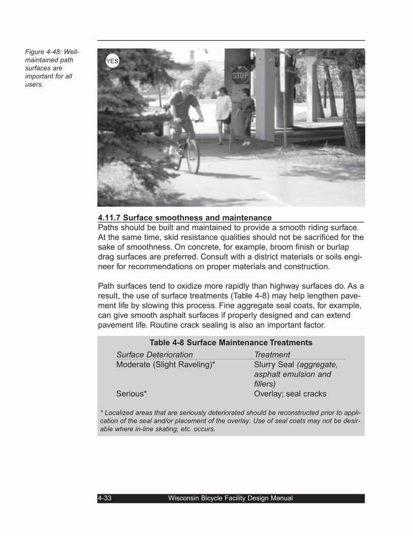
4.11.7 Surface smoothness and maintenance
Paths should be built and maintained to provide a smooth riding surface.
At the same time, skid resistance qualities should not be sacrificed for the
sake of smoothness. On concrete, for example, broom finish or burlap
drag surfaces are preferred. Consult with a district materials or soils engi-
neer for recommendations on proper materials and construction.
Path surfaces tend to oxidize more rapidly than highway surfaces do. As a
result, the use of surface treatments (Table 4-8) may help lengthen pave-
ment life by slowing this process. Fine aggregate seal coats, for example,
can give smooth asphalt surfaces if properly designed and can extend
pavement life. Routine crack sealing is also an important factor.
4-33 Wisconsin Bicycle Facility Design Manual
Figure 4-48: Well-maintained pathsurfaces areimportant for allusers.
Table 4-8 Surface Maintenance Treatments
Surface Deterioration Treatment Moderate (Slight Raveling)* Slurry Seal (aggregate,
asphalt emulsion andfillers)
Serious* Overlay; seal cracks
* Localized areas that are seriously deteriorated should be reconstructed prior to appli-cation of the seal and/or placement of the overlay. Use of seal coats may not be desir-able where in-line skating, etc. occurs.
YES
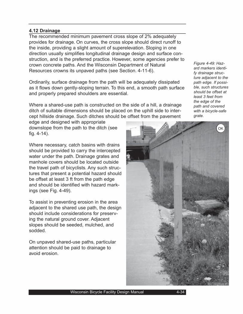
4.12 Drainage
The recommended minimum pavement cross slope of 2% adequately
provides for drainage. On curves, the cross slope should direct runoff to
the inside, providing a slight amount of superelevation. Sloping in one
direction usually simplifies longitudinal drainage design and surface con-
struction, and is the preferred practice. However, some agencies prefer to
crown concrete paths. And the Wisconsin Department of Natural
Resources crowns its unpaved paths (see Section. 4-11-6).
Ordinarily, surface drainage from the path will be adequately dissipated
as it flows down gently-sloping terrain. To this end, a smooth path surface
and properly prepared shoulders are essential.
Where a shared-use path is constructed on the side of a hill, a drainage
ditch of suitable dimensions should be placed on the uphill side to inter-
cept hillside drainage. Such ditches should be offset from the pavement
edge and designed with appropriate
downslope from the path to the ditch (see
fig. 4-14).
Where necessary, catch basins with drains
should be provided to carry the intercepted
water under the path. Drainage grates and
manhole covers should be located outside
the travel path of bicyclists. Any such struc-
tures that present a potential hazard should
be offset at least 3 ft from the path edge
and should be identified with hazard mark-
ings (see Fig. 4-49).
To assist in preventing erosion in the area
adjacent to the shared use path, the design
should include considerations for preserv-
ing the natural ground cover. Adjacent
slopes should be seeded, mulched, and
sodded.
On unpaved shared-use paths, particular
attention should be paid to drainage to
avoid erosion.
Figure 4-49: Haz-ard markers identi-fy drainage struc-ture adjacent to thepath edge. If possi-ble, such structuresshould be offset atleast 3 feet fromthe edge of thepath and coveredwith a bicycle-safegrate.
Wisconsin Bicycle Facility Design Manual 4-34
OK
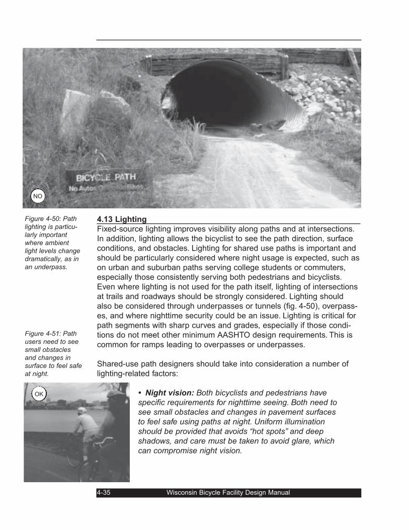
4.13 Lighting
Fixed-source lighting improves visibility along paths and at intersections.
In addition, lighting allows the bicyclist to see the path direction, surface
conditions, and obstacles. Lighting for shared use paths is important and
should be particularly considered where night usage is expected, such as
on urban and suburban paths serving college students or commuters,
especially those consistently serving both pedestrians and bicyclists.
Even where lighting is not used for the path itself, lighting of intersections
at trails and roadways should be strongly considered. Lighting should
also be considered through underpasses or tunnels (fig. 4-50), overpass-
es, and where nighttime security could be an issue. Lighting is critical for
path segments with sharp curves and grades, especially if those condi-
tions do not meet other minimum AASHTO design requirements. This is
common for ramps leading to overpasses or underpasses.
Shared-use path designers should take into consideration a number of
lighting-related factors:
• Night vision: Both bicyclists and pedestrians havespecific requirements for nighttime seeing. Both need tosee small obstacles and changes in pavement surfacesto feel safe using paths at night. Uniform illuminationshould be provided that avoids “hot spots” and deepshadows, and care must be taken to avoid glare, whichcan compromise night vision.
4-35 Wisconsin Bicycle Facility Design Manual
Figure 4-50: Pathlighting is particu-larly importantwhere ambientlight levels changedramatically, as inan underpass.
Figure 4-51: Pathusers need to seesmall obstaclesand changes insurface to feel safeat night.
OK
NO
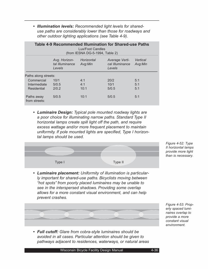
• Illumination levels: Recommended light levels for shared-use paths are considerably lower than those for roadways andother outdoor lighting applications (see Table 4-9).
• Luminaire Design: Typical pole mounted roadway lights area poor choice for illuminating narrow paths. Standard Type IIhorizontal lamps create spill light off the path, and requireexcess wattage and/or more frequent placement to maintainuniformity. If pole mounted lights are specified, Type I horizon-tal lamps should be used.
• Luminaire placement: Uniformity of illumination is particular-ly important for shared-use paths. Bicyclists moving between“hot spots” from poorly placed luminaires may be unable tosee in the interspersed shadows. Providing some overlapallows for a more constant visual environment, and can helpprevent crashes.
• Full cutoff: Glare from cobra-style luminaires should beavoided in all cases. Particular attention should be given topathways adjacent to residences, waterways, or natural areas
Wisconsin Bicycle Facility Design Manual 4-36
Figure 4-52: TypeII horizontal lampsprovide more lightthan is necessary.
Figure 4-53: Prop-erly spaced lumi-naires overlap toprovide a moreconstant visualenvironment.
Table 4-9 Recommended Illumination for Shared-use PathsLux/Foot Candles
(from IESNA DG-5-1994, Table 2)
Commercial
Intermediate
Residential
Paths away
from streets:
Avg. Horizon-tal IlluminanceLevels
10/1
5/0.5
2/0.2
5/0.5
HorizontalAvg:Min
4:1
4:1
10:1
10:1
Average Verti-cal IlluminanceLevels
20/2
10/1
5/0.5
5/0.5
VerticalAvg:Min
5:1
5:1
5:1
5:1
Paths along streets:
Type I Type II
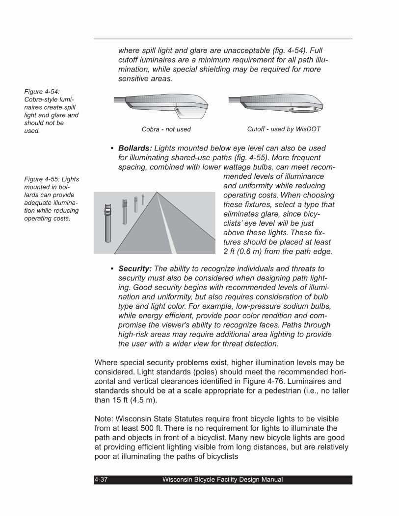
where spill light and glare are unacceptable (fig. 4-54). Fullcutoff luminaires are a minimum requirement for all path illu-mination, while special shielding may be required for moresensitive areas.
• Bollards: Lights mounted below eye level can also be usedfor illuminating shared-use paths (fig. 4-55). More frequentspacing, combined with lower wattage bulbs, can meet recom-
mended levels of illuminanceand uniformity while reducingoperating costs. When choosingthese fixtures, select a type thateliminates glare, since bicy-clists’ eye level will be justabove these lights. These fix-tures should be placed at least2 ft (0.6 m) from the path edge.
• Security: The ability to recognize individuals and threats tosecurity must also be considered when designing path light-ing. Good security begins with recommended levels of illumi-nation and uniformity, but also requires consideration of bulbtype and light color. For example, low-pressure sodium bulbs,while energy efficient, provide poor color rendition and com-promise the viewer’s ability to recognize faces. Paths throughhigh-risk areas may require additional area lighting to providethe user with a wider view for threat detection.
Where special security problems exist, higher illumination levels may be
considered. Light standards (poles) should meet the recommended hori-
zontal and vertical clearances identified in Figure 4-76. Luminaires and
standards should be at a scale appropriate for a pedestrian (i.e., no taller
than 15 ft (4.5 m).
Note: Wisconsin State Statutes require front bicycle lights to be visible
from at least 500 ft. There is no requirement for lights to illuminate the
path and objects in front of a bicyclist. Many new bicycle lights are good
at providing efficient lighting visible from long distances, but are relatively
poor at illuminating the paths of bicyclists
4-37 Wisconsin Bicycle Facility Design Manual
Figure 4-54:Cobra-style lumi-naires create spilllight and glare andshould not beused.
Figure 4-55: Lightsmounted in bol-lards can provideadequate illumina-tion while reducingoperating costs.
Cobra - not used Cutoff - used by WisDOT
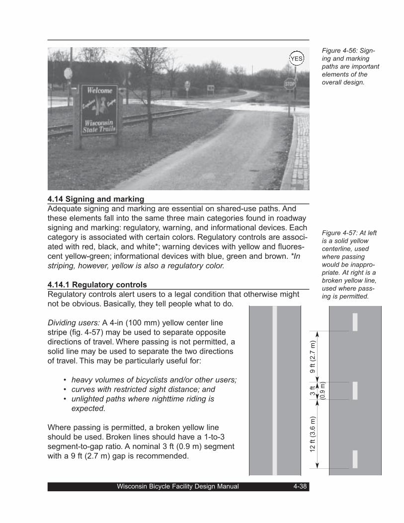
4.14 Signing and marking
Adequate signing and marking are essential on shared-use paths. And
these elements fall into the same three main categories found in roadway
signing and marking: regulatory, warning, and informational devices. Each
category is associated with certain colors. Regulatory controls are associ-
ated with red, black, and white*; warning devices with yellow and fluores-
cent yellow-green; informational devices with blue, green and brown. *Instriping, however, yellow is also a regulatory color.
4.14.1 Regulatory controls
Regulatory controls alert users to a legal condition that otherwise might
not be obvious. Basically, they tell people what to do.
Dividing users: A 4-in (100 mm) yellow center line
stripe (fig. 4-57) may be used to separate opposite
directions of travel. Where passing is not permitted, a
solid line may be used to separate the two directions
of travel. This may be particularly useful for:
• heavy volumes of bicyclists and/or other users;• curves with restricted sight distance; and• unlighted paths where nighttime riding is
expected.
Where passing is permitted, a broken yellow line
should be used. Broken lines should have a 1-to-3
segment-to-gap ratio. A nominal 3 ft (0.9 m) segment
with a 9 ft (2.7 m) gap is recommended.
Wisconsin Bicycle Facility Design Manual 4-38
Figure 4-56: Sign-ing and markingpaths are importantelements of theoverall design.
Figure 4-57: At leftis a solid yellowcenterline, usedwhere passingwould be inappro-priate. At right is abroken yellow line,used where pass-ing is permitted.
12 f
t (3
.6 m
)9 f
t (2
.7 m
)3 f
t
(0.9
m)
YES
Where there is a bollard in the center of the path, a, a solid yellow center-
line should be split to go around it (fig. 4-58) and the bollard should be
reflectorized. If designers wish to separate different types of users, a solid
white line may be used. The R5-3 sign (fig. 4-59) may be used to supple-
ment the line (fig. 4-60). For more information on separation, see Section
4.17.1. In addition, white edge lines can help where significant night-time
bicycle traffic is expected (e.g., near a university campus).
Excluding unwanted users: Typically, unauthorized motor vehicles are
prohibited from shared-use paths. The No Motor Vehicles (R5-3) sign may
be installed at the path entrance (fig. 4-61). Where other potential users
are prohibited (e.g., horses, pedestrians, motor-driven cycles, etc.),
appropriate combinations or groupings of these legends into a single sign
may be used. These are described in Section 2B.31 of the MUTCD. Other
means to discourage motor vehicles are discussed in Section 4.17.3.
Establishing right of way at intersections: Regulatory signs and markings
are typically used to assign right of way at intersections, whether at
path/path crossings or at path/roadway crossings.
4-39 Wisconsin Bicycle Facility Design Manual
Figure 4-58: Thecenterline stripeshould split to goaround bollards.
Figure 4-59: Signused to separatepath users by type.
Figure 4-60 (right):One approach toseparating bicy-clists and pedestri-ans. Expect onlymodest successwith treatmentsthat do not physi-cally separate bicy-clists and pedestri-ans.
Figure 4-61: The“No Motor Vehi-cles” sign may beused at theentrance to ashared-use path.
NO
MOTOR
VEHICLES
R5-3
LEFT RIGHT
KEEP
R5-3
10 ft (3 m)
Bollard2 ft (0.9 m)
OK
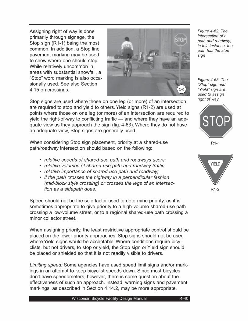
Assigning right of way is done
primarily through signage, the
Stop sign (R1-1) being the most
common. In addition, a Stop line
pavement marking may be used
to show where one should stop.
While relatively uncommon in
areas with substantial snowfall, a
“Stop” word marking is also occa-
sionally used. See also Section
4.15 on crossings.
Stop signs are used where those on one leg (or more) of an intersection
are required to stop and yield to others. Yield signs (R1-2) are used at
points where those on one leg (or more) of an intersection are required to
yield the right-of-way to conflicting traffic — and where they have an ade-
quate view as they approach the sign (fig. 4-63). Where they do not have
an adequate view, Stop signs are generally used.
When considering Stop sign placement, priority at a shared-use
path/roadway intersection should based on the following:
• relative speeds of shared-use path and roadways users;• relative volumes of shared-use path and roadway traffic;• relative importance of shared-use path and roadway;• if the path crosses the highway in a perpendicular fashion
(mid-block style crossing) or crosses the legs of an intersec-tion as a sidepath does.
Speed should not be the sole factor used to determine priority, as it is
sometimes appropriate to give priority to a high-volume shared-use path
crossing a low-volume street, or to a regional shared-use path crossing a
minor collector street.
When assigning priority, the least restrictive appropriate control should be
placed on the lower priority approaches. Stop signs should not be used
where Yield signs would be acceptable. Where conditions require bicy-
clists, but not drivers, to stop or yield, the Stop sign or Yield sign should
be placed or shielded so that it is not readily visible to drivers.
Limiting speed: Some agencies have used speed limit signs and/or mark-
ings in an attempt to keep bicyclist speeds down. Since most bicycles
don't have speedometers, however, there is some question about the
effectiveness of such an approach. Instead, warning signs and pavement
markings, as described in Section 4.14.2, may be more appropriate.
Wisconsin Bicycle Facility Design Manual 4-40
Figure 4-62: Theintersection of apath and roadway;in this instance, thepath has the stopsign
Figure 4-63: The“Stop” sign and“Yield” sign areused to assignright of way.
STOP
YIELD
R1-1
R1-2
OK
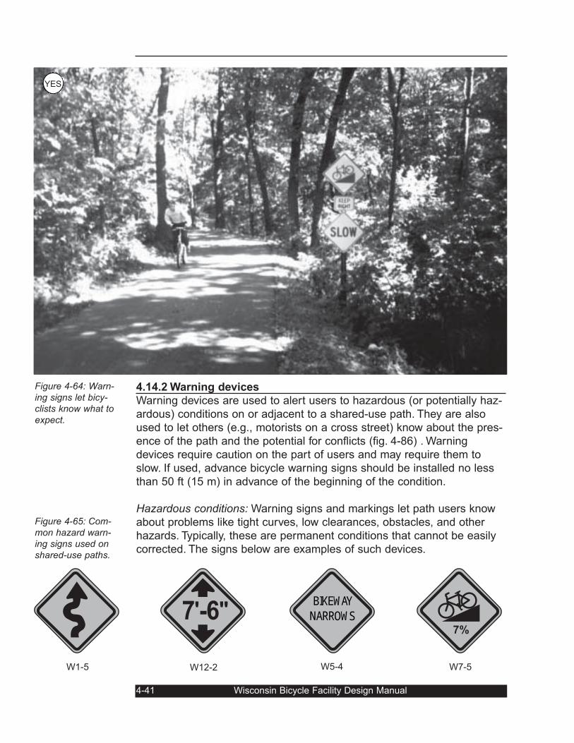
4.14.2 Warning devices
Warning devices are used to alert users to hazardous (or potentially haz-
ardous) conditions on or adjacent to a shared-use path. They are also
used to let others (e.g., motorists on a cross street) know about the pres-
ence of the path and the potential for conflicts (fig. 4-86) . Warning
devices require caution on the part of users and may require them to
slow. If used, advance bicycle warning signs should be installed no less
than 50 ft (15 m) in advance of the beginning of the condition.
Hazardous conditions: Warning signs and markings let path users know
about problems like tight curves, low clearances, obstacles, and other
hazards. Typically, these are permanent conditions that cannot be easily
corrected. The signs below are examples of such devices.
4-41 Wisconsin Bicycle Facility Design Manual
Figure 4-64: Warn-ing signs let bicy-clists know what toexpect.
Figure 4-65: Com-mon hazard warn-ing signs used onshared-use paths.
7'-6"BIKEWAYNARROWS
7%
W1-5 W12-2 W5-4 W7-5
YES
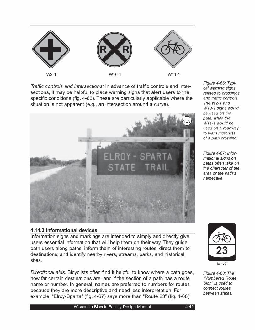
Traffic controls and intersections: In advance of traffic controls and inter-
sections, it may be helpful to place warning signs that alert users to the
specific conditions (fig. 4-66). These are particularly applicable where the
situation is not apparent (e.g., an intersection around a curve).
4.14.3 Informational devices
Information signs and markings are intended to simply and directly give
users essential information that will help them on their way. They guide
path users along paths; inform them of interesting routes; direct them to
destinations; and identify nearby rivers, streams, parks, and historical
sites.
Directional aids: Bicyclists often find it helpful to know where a path goes,
how far certain destinations are, and if the section of a path has a route
name or number. In general, names are preferred to numbers for routes
because they are more descriptive and need less interpretation. For
example, “Elroy-Sparta” (fig. 4-67) says more than “Route 23” (fig. 4-68).
Wisconsin Bicycle Facility Design Manual 4-42
Figure 4-66: Typi-cal warning signsrelated to crossingsand traffic controls.The W2-1 andW10-1 signs wouldbe used on thepath, while theW11-1 would beused on a roadwayto warn motoristsof a path crossing.
Figure 4-67: Infor-mational signs onpaths often take onthe character of thearea or the path’snamesake.
Figure 4-68: The“Numbered RouteSign” is used toconnect routesbetween states.
R R
23
W2-1 W10-1 W11-1
M1-9
YES
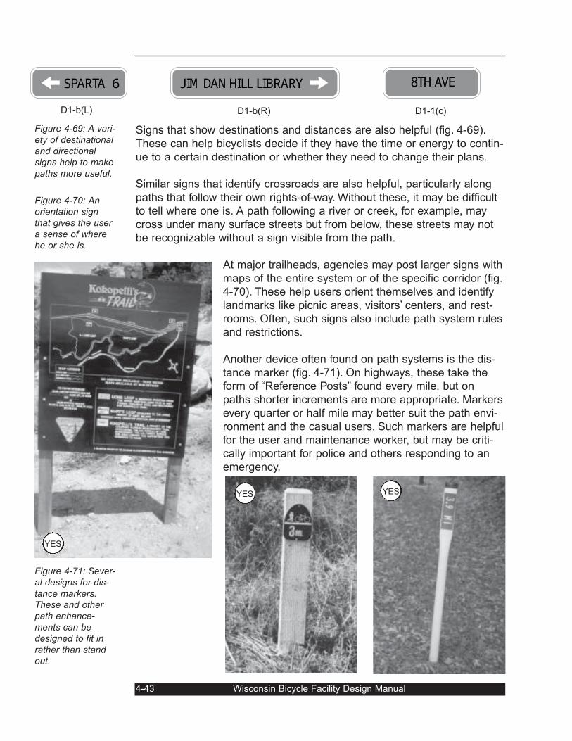
Signs that show destinations and distances are also helpful (fig. 4-69).
These can help bicyclists decide if they have the time or energy to contin-
ue to a certain destination or whether they need to change their plans.
Similar signs that identify crossroads are also helpful, particularly along
paths that follow their own rights-of-way. Without these, it may be difficult
to tell where one is. A path following a river or creek, for example, may
cross under many surface streets but from below, these streets may not
be recognizable without a sign visible from the path.
At major trailheads, agencies may post larger signs with
maps of the entire system or of the specific corridor (fig.
4-70). These help users orient themselves and identify
landmarks like picnic areas, visitors’ centers, and rest-
rooms. Often, such signs also include path system rules
and restrictions.
Another device often found on path systems is the dis-
tance marker (fig. 4-71). On highways, these take the
form of “Reference Posts” found every mile, but on
paths shorter increments are more appropriate. Markers
every quarter or half mile may better suit the path envi-
ronment and the casual users. Such markers are helpful
for the user and maintenance worker, but may be criti-
cally important for police and others responding to an
emergency.
4-43 Wisconsin Bicycle Facility Design Manual
Figure 4-69: A vari-ety of destinationaland directionalsigns help to makepaths more useful.
Figure 4-70: Anorientation signthat gives the usera sense of wherehe or she is.
Figure 4-71: Sever-al designs for dis-tance markers.These and otherpath enhance-ments can bedesigned to fit inrather than standout.
SPARTA 6D1-b(L)
JIM DAN HILL LIBRARYD1-b(R)
8TH AVED1-1(c)
YESYES
YES
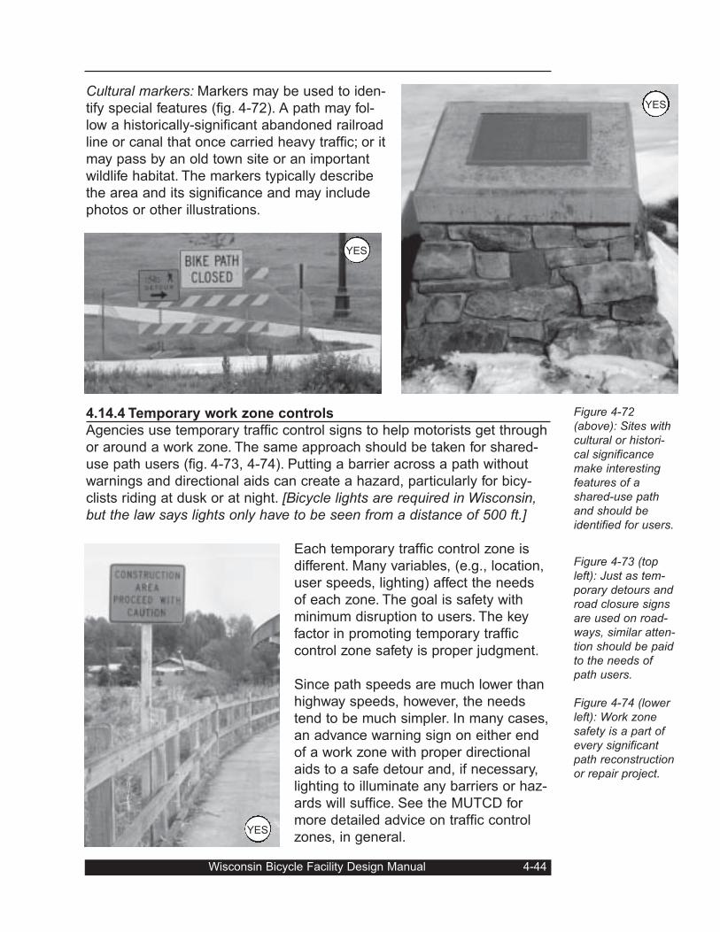
Cultural markers: Markers may be used to iden-
tify special features (fig. 4-72). A path may fol-
low a historically-significant abandoned railroad
line or canal that once carried heavy traffic; or it
may pass by an old town site or an important
wildlife habitat. The markers typically describe
the area and its significance and may include
photos or other illustrations.
4.14.4 Temporary work zone controls
Agencies use temporary traffic control signs to help motorists get through
or around a work zone. The same approach should be taken for shared-
use path users (fig. 4-73, 4-74). Putting a barrier across a path without
warnings and directional aids can create a hazard, particularly for bicy-
clists riding at dusk or at night. [Bicycle lights are required in Wisconsin,but the law says lights only have to be seen from a distance of 500 ft.]
Each temporary traffic control zone is
different. Many variables, (e.g., location,
user speeds, lighting) affect the needs
of each zone. The goal is safety with
minimum disruption to users. The key
factor in promoting temporary traffic
control zone safety is proper judgment.
Since path speeds are much lower than
highway speeds, however, the needs
tend to be much simpler. In many cases,
an advance warning sign on either end
of a work zone with proper directional
aids to a safe detour and, if necessary,
lighting to illuminate any barriers or haz-
ards will suffice. See the MUTCD for
more detailed advice on traffic control
zones, in general.
Wisconsin Bicycle Facility Design Manual 4-44
Figure 4-72(above): Sites withcultural or histori-cal significancemake interestingfeatures of ashared-use pathand should beidentified for users.
Figure 4-73 (topleft): Just as tem-porary detours androad closure signsare used on road-ways, similar atten-tion should be paidto the needs ofpath users.
Figure 4-74 (lowerleft): Work zonesafety is a part ofevery significantpath reconstructionor repair project.
YES
YES
YES
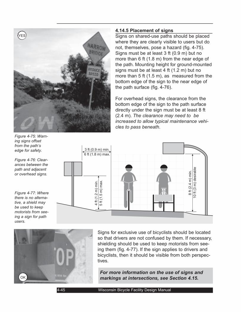
4.14.5 Placement of signs
Signs on shared-use paths should be placed
where they are clearly visible to users but do
not, themselves, pose a hazard (fig. 4-75).
Signs must be at least 3 ft (0.9 m) but no
more than 6 ft (1.8 m) from the near edge of
the path. Mounting height for ground-mounted
signs must be at least 4 ft (1.2 m) but no
more than 5 ft (1.5 m), as measured from the
bottom edge of the sign to the near edge of
the path surface (fig. 4-76).
For overhead signs, the clearance from the
bottom edge of the sign to the path surface
directly under the sign must be at least 8 ft
(2.4 m). The clearance may need to beincreased to allow typical maintenance vehi-cles to pass beneath.
Signs for exclusive use of bicyclists should be located
so that drivers are not confused by them. If necessary,
shielding should be used to keep motorists from see-
ing them (fig. 4-77). If the sign applies to drivers and
bicyclists, then it should be visible from both perspec-
tives.
4-45 Wisconsin Bicycle Facility Design Manual
Figure 4-75: Warn-ing signs offsetfrom the path’sedge for safety.
Figure 4-76: Clear-ances between thepath and adjacentor overhead signs.
Figure 4-77: Wherethere is no alterna-tive, a shield maybe used to keepmotorists from see-ing a sign for pathusers.
3 ft (0.9 m) min.
6 ft (1.8 m) max.
4 f
t (1
.2 m
) m
in.
5 f
t (1
.5 m
) m
ax.
8 f
t (2
.4 m
) m
in.
10 f
t (3
m)
desirable
For more information on the use of signs and
markings at intersections, see Section 4.15.OK
YES
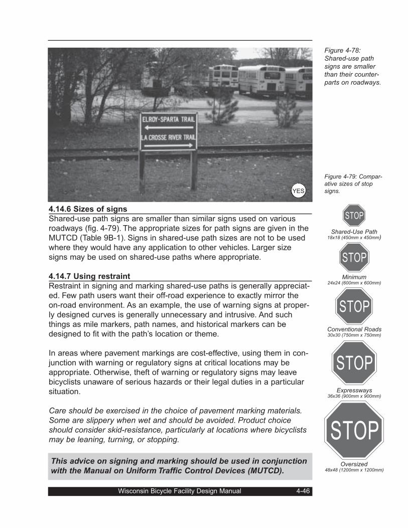
STOP
STOP
STOP
STOP
STOP
4.14.6 Sizes of signs
Shared-use path signs are smaller than similar signs used on various
roadways (fig. 4-79). The appropriate sizes for path signs are given in the
MUTCD (Table 9B-1). Signs in shared-use path sizes are not to be used
where they would have any application to other vehicles. Larger size
signs may be used on shared-use paths where appropriate.
4.14.7 Using restraint
Restraint in signing and marking shared-use paths is generally appreciat-
ed. Few path users want their off-road experience to exactly mirror the
on-road environment. As an example, the use of warning signs at proper-
ly designed curves is generally unnecessary and intrusive. And such
things as mile markers, path names, and historical markers can be
designed to fit with the path’s location or theme.
In areas where pavement markings are cost-effective, using them in con-
junction with warning or regulatory signs at critical locations may be
appropriate. Otherwise, theft of warning or regulatory signs may leave
bicyclists unaware of serious hazards or their legal duties in a particular
situation.
Care should be exercised in the choice of pavement marking materials.Some are slippery when wet and should be avoided. Product choiceshould consider skid-resistance, particularly at locations where bicyclistsmay be leaning, turning, or stopping.
Wisconsin Bicycle Facility Design Manual 4-46
Figure 4-78:Shared-use pathsigns are smallerthan their counter-parts on roadways.
Figure 4-79: Compar-ative sizes of stopsigns.
Shared-Use Path18x18 (450mm x 450mm)
Minimum24x24 (600mm x 600mm)
Conventional Roads30x30 (750mm x 750mm)
Expressways36x36 (900mm x 900mm)
Oversized48x48 (1200mm x 1200mm)
This advice on signing and marking should be used in conjunction
with the Manual on Uniform Traffic Control Devices (MUTCD).
YES
4.15 Path-Roadway Crossings
Roadway crossings can present some of the most difficult challenges in
shared-use path design. Due to a wide variety of potential conflicts, opti-
mal location and careful design are of paramount importance to the safe-
ty of path users and motorists alike. Historically, some designers have
attempted to force bicyclists to stop, dismount, and walk across at cross-
ings. However, experience has shown that such an approach seldom
works. Ultimately, a good design is based on balancing the safety and
convenience of all users in a fair and reasonable manner.
The crossing strategies discussed in this
section should be considered basic guide-
lines, not absolutes. Each crossing is
unique, with its own geometrics, traffic
characteristics, and constraints. As a
result, sound engineering judgment is a
key ingredient to a successful solution.
4.15.1 Choosing crossing locations
Difficult crossing design problems can
sometimes be avoided or simplified by
paying careful attention to location. At a
network planning scale, choosing a corri-
dor with the fewest obvious conflicts can
solve many problems. For instance, choos-
ing to build on a rail-trail or within a river
corridor (Fig. 4-81) can eliminate some
4-47 Wisconsin Bicycle Facility Design Manual
Figure 4-80: Achallenging loca-tion to develop acrossing.
Fig. 4-81: Ashared-use pathfollows a river cor-ridor and takes fulladvantage of agrade separationwith a freeway.
OK
YES
intersections entirely. Conversely, placing a
path along an urban street will introduce
path users to many side-street intersection
and driveway conflict points.
At the project level, path alignment may be
shifted to avoid a hazardous location (e.g.,
a blind highway curve or busy intersec-
tion). Figure 4-82 shows an example with
two possible alignments, one with a seri-
ous sight obstruction.
Path intersections and approaches should
be on relatively flat grades. A steep incline
with a stop sign at the bottom will make it
difficult for less experienced bicyclists to
stop in time. And such an incline will
increase the path’s design speed and the
stopping sight distance.
Unwary bicyclists may not begin slowing down soon enough to safely
come to a stop (fig. 4-83). They may brake too hard and crash or ride into
the intersection without being able to stop, particularly in wet or icy condi-
tions. If such conditions cannot be avoided, advance warning signs and
increased stopping sight distances should be provided.
For these reasons, providing an appropriate length of
level path before the intersection will allow bicyclists to
slow down. See Section 4.9. for a discussion of pathrunout distances at the bottom of grades.
4.15.2 Intersection: yes or no?
When deciding how to handle a path/roadway crossing, the first step is
an obvious one: determine whether an intersection or a grade separation
is the answer. On the one hand, choosing an intersection approach
involves addressing how bicyclists and motorists will interact at the cross-
ing — who must yield to whom; whether there are sufficient gaps in road-
way traffic; what roadway and traffic control changes may be required;
and so on.
On the other hand, choosing a grade separation eliminates the intersec-
tion entirely, as mentioned in the previous section. It may, however,
require designers to find an accessible site that will accommodate the
ramps and structure.
Wisconsin Bicycle Facility Design Manual 4-48
Fig.ure 4-82: Prop-er path alignmentcan help eliminatesight obstructions.Alignment “B,” forexample, gives abetter crossinglocation than doesalignment “A.”
Figure 4-83: Pathroadway intersec-tions should not beplaced at the bot-tom of a grade.
Site A
Site B
Sight Obstruction
Alignment A
Alignm
ent B
If the roadway to be crossed is a controlled-access freeway, there is no
decision to be made; the crossing must be grade separated. The ques-
tions remaining involve where to put the grade separation, whether to go
over or under, and whether it can safely be combined with a surface
street crossing (see Section 4.15.17).
At the other end of the spectrum, crossing a quiet residential street (fig.
4-85) or low-traffic rural road (fig. .4-86) would almost never warrant a
grade separation. The only situation where one would likely make sense
would be if the path corridor was already lower or higher than the street
or there were significant sight limitations at the intersection. Examples
include below-grade railroad right-of-ways or waterways.
4-49 Wisconsin Bicycle Facility Design Manual
Figure 4-84: Agrade separation is the only optionfor getting pathusers across acontrolled-accessfreeway.
Figure 4-85: A low-volume residentialstreet crossingneeds very littlespecial attention.
YES
4.15.3 Rural vs. urban/suburban locations
Between the extremes, the decision to create a path/roadway intersection
or a grade separation first involves whether the crossing is rural or
urban/suburban in character. Typical differences include traffic speeds,
path and roadway volumes, roadway geometrics, surrounding develop-
ment, and likely path users.
4.15.3.1 Rural path crossings
Rural paths typically cross high-speed roadways with a wide range of
traffic volumes. Where volumes are low, crossing distances are moderate,
and sight distances are good, little is required beyond basic signing and
marking (fig. 4-86). In some cases, the crossing location may need to be
shifted to improve sight distance (see Section 4.15.1).
Crossing moderate-volume rural high-
ways, on the other hand, may require
more extensive provisions, depending
on the path’s proximity to a community
or recreational area and likely level of
use. In some cases, a combination of
signs, pavement markings, and a medi-
an refuge may be adequate. The refuge
(see Section 4.15.4.2) allows bicyclists
to cross half of the roadway at a time
(fig. 4-87). Traffic signals, however, are
seldom appropriate for rural path cross-
ings, due to relatively low path volumes
and high highway speeds.
Wisconsin Bicycle Facility Design Manual 4-50
Figure 4-86: Ashared-use pathcrosses a rurallow-volume high-way. Signing andmarking, combinedwith good sight dis-tance, are the pri-mary requirements.
Figure 4-87: A pathcrossing at a mod-erate volume high-way combines araised medianrefuge with signingand marking.
YES
YES
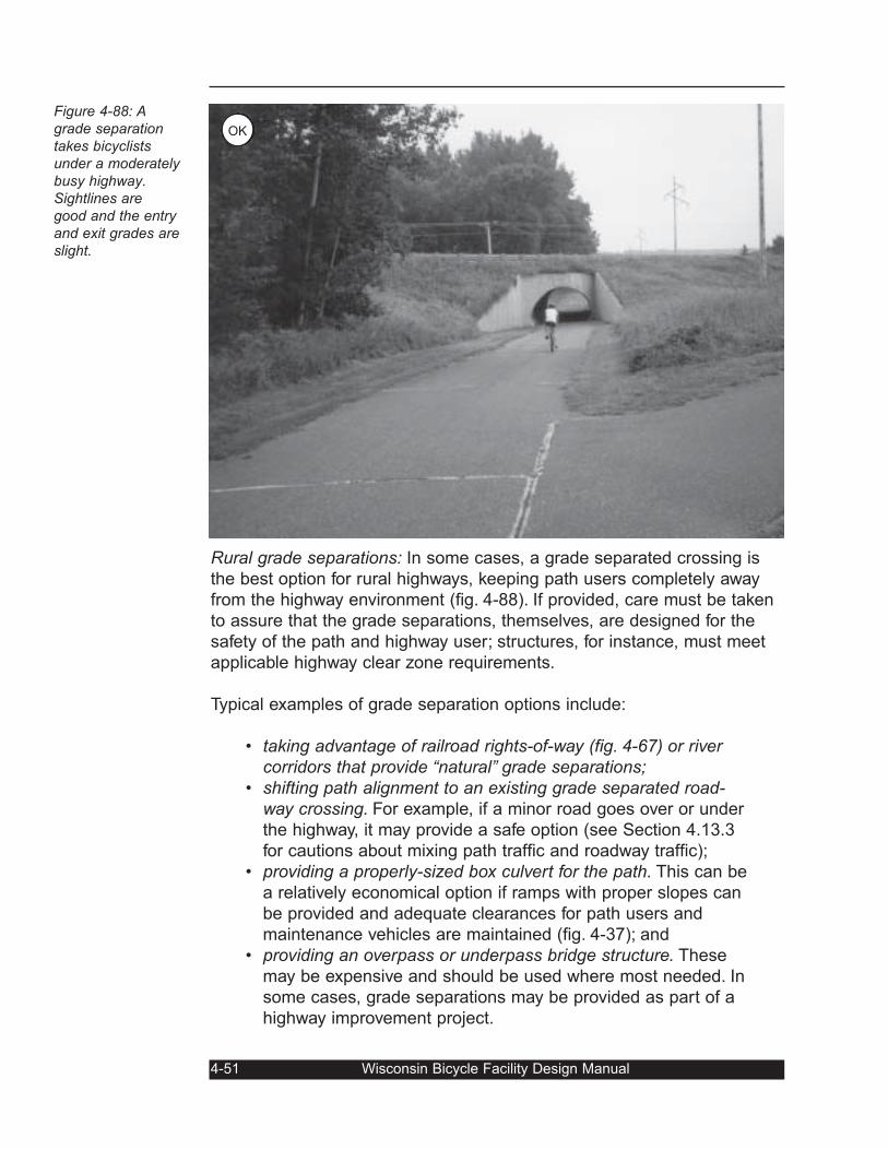
Rural grade separations: In some cases, a grade separated crossing is
the best option for rural highways, keeping path users completely away
from the highway environment (fig. 4-88). If provided, care must be taken
to assure that the grade separations, themselves, are designed for the
safety of the path and highway user; structures, for instance, must meet
applicable highway clear zone requirements.
Typical examples of grade separation options include:
• taking advantage of railroad rights-of-way (fig. 4-67) or rivercorridors that provide “natural” grade separations;
• shifting path alignment to an existing grade separated road-way crossing. For example, if a minor road goes over or under
the highway, it may provide a safe option (see Section 4.13.3
for cautions about mixing path traffic and roadway traffic);
• providing a properly-sized box culvert for the path. This can be
a relatively economical option if ramps with proper slopes can
be provided and adequate clearances for path users and
maintenance vehicles are maintained (fig. 4-37); and
• providing an overpass or underpass bridge structure. These
may be expensive and should be used where most needed. In
some cases, grade separations may be provided as part of a
highway improvement project.
4-51 Wisconsin Bicycle Facility Design Manual
Figure 4-88: Agrade separationtakes bicyclistsunder a moderatelybusy highway.Sightlines aregood and the entryand exit grades areslight.
OK
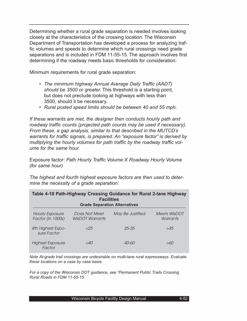
Determining whether a rural grade separation is needed involves looking
closely at the characteristics of the crossing location. The Wisconsin
Department of Transportation has developed a process for analyzing traf-
fic volumes and speeds to determine which rural crossings need grade
separations and is included in FDM 11-55-15. The approach involves first
determining if the roadway meets basic thresholds for consideration:
Minimum requirements for rural grade separation:
• The minimum highway Annual Average Daily Traffic (AADT)should be 3500 or greater. This threshold is a starting point,
but does not preclude looking at highways with less than
3500, should it be necessary.
• Rural posted speed limits should be between 40 and 55 mph.
If these warrants are met, the designer then conducts hourly path androadway traffic counts (projected path counts may be used if necessary).From these, a gap analysis, similar to that described in the MUTCD’swarrants for traffic signals, is prepared. An “exposure factor” is derived bymultiplying the hourly volumes for path traffic by the roadway traffic vol-ume for the same hour.
Exposure factor: Path Hourly Traffic Volume X Roadway Hourly Volume(for same hour)
The highest and fourth highest exposure factors are then used to deter-mine the necessity of a grade separation:
Note At-grade trail crossings are undesirable on multi-lane rural expressways. Evaluatethese locations on a case by case basis.
For a copy of the Wisconsin DOT guidance, see “Permanent Public Trails CrossingRural Roads in FDM 11-55-15.
Wisconsin Bicycle Facility Design Manual 4-52
Hourly ExposureFactor (in 1000s)
4th Highest Expo-sure Factor
Highest ExposureFactor
Does Not MeetWisDOT Warrants
<25
<40
May Be Justified
25-35
40-60
Meets WisDOTWarrants
>35
>60
Table 4-10 Path-Highway Crossing Guidance for Rural 2-lane Highway
FacilitiesGrade Separation Alternatives
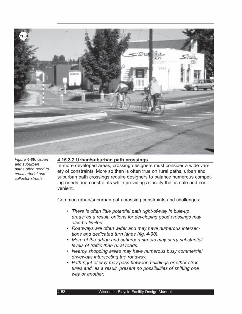
4.15.3.2 Urban/suburban path crossings
In more developed areas, crossing designers must consider a wide vari-
ety of constraints. More so than is often true on rural paths, urban and
suburban path crossings require designers to balance numerous compet-
ing needs and constraints while providing a facility that is safe and con-
venient.
Common urban/suburban path crossing constraints and challenges:
• There is often little potential path right-of-way in built-upareas; as a result, options for developing good crossings mayalso be limited.
• Roadways are often wider and may have numerous intersec-tions and dedicated turn lanes (fig. 4-90).
• More of the urban and suburban streets may carry substantiallevels of traffic than rural roads.
• Nearby shopping areas may have numerous busy commercialdriveways intersecting the roadway.
• Path right-of-way may pass between buildings or other struc-tures and, as a result, present no possibilities of shifting oneway or another.
4-53 Wisconsin Bicycle Facility Design Manual
Figure 4-89: Urbanand suburbanpaths often need tocross arterial andcollector streets.
YES
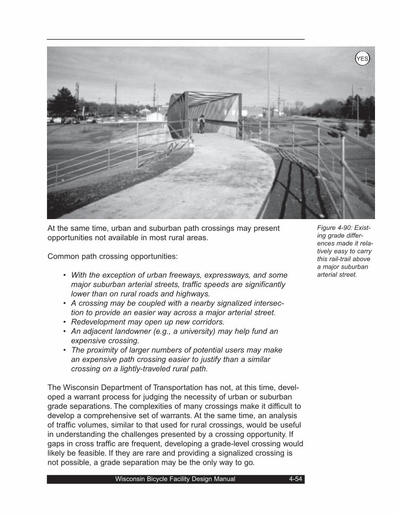
At the same time, urban and suburban path crossings may present
opportunities not available in most rural areas.
Common path crossing opportunities:
• With the exception of urban freeways, expressways, and somemajor suburban arterial streets, traffic speeds are significantlylower than on rural roads and highways.
• A crossing may be coupled with a nearby signalized intersec-tion to provide an easier way across a major arterial street.
• Redevelopment may open up new corridors.• An adjacent landowner (e.g., a university) may help fund an
expensive crossing.• The proximity of larger numbers of potential users may make
an expensive path crossing easier to justify than a similarcrossing on a lightly-traveled rural path.
The Wisconsin Department of Transportation has not, at this time, devel-
oped a warrant process for judging the necessity of urban or suburban
grade separations. The complexities of many crossings make it difficult to
develop a comprehensive set of warrants. At the same time, an analysis
of traffic volumes, similar to that used for rural crossings, would be useful
in understanding the challenges presented by a crossing opportunity. If
gaps in cross traffic are frequent, developing a grade-level crossing would
likely be feasible. If they are rare and providing a signalized crossing is
not possible, a grade separation may be the only way to go.
Wisconsin Bicycle Facility Design Manual 4-54
Figure 4-90: Exist-ing grade differ-ences made it rela-tively easy to carrythis rail-trail abovea major suburbanarterial street.
YES
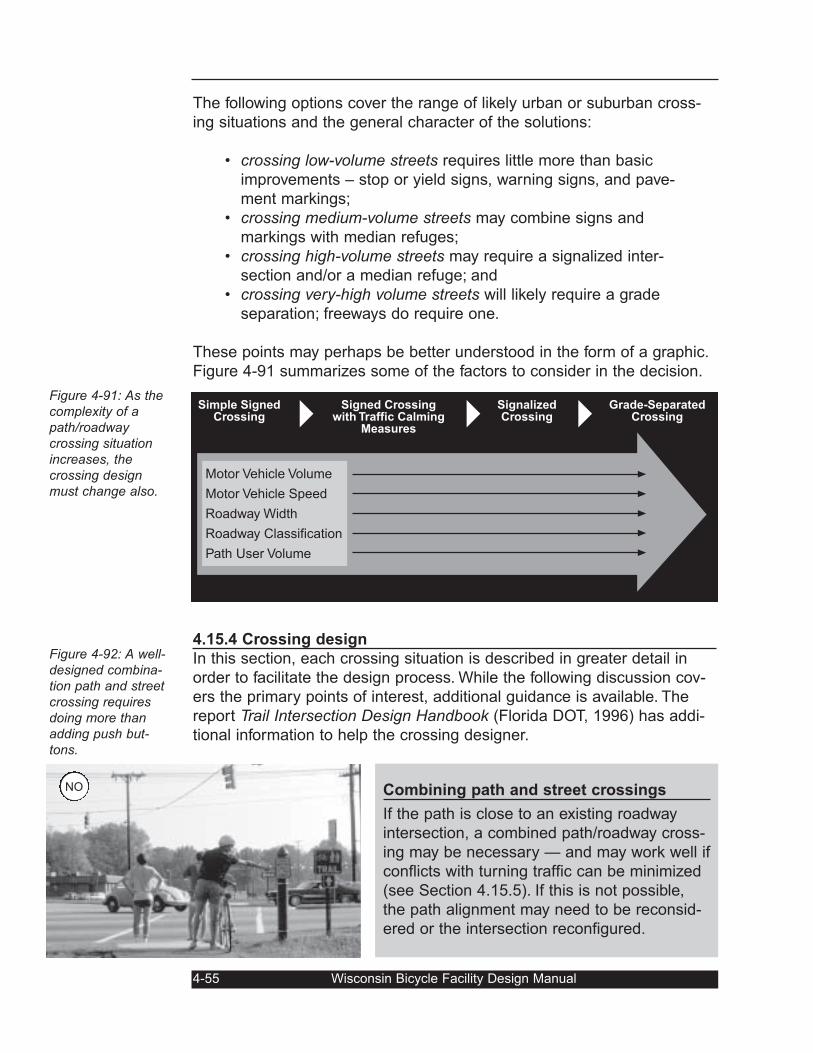
The following options cover the range of likely urban or suburban cross-
ing situations and the general character of the solutions:
• crossing low-volume streets requires little more than basic
improvements – stop or yield signs, warning signs, and pave-
ment markings;
• crossing medium-volume streets may combine signs and
markings with median refuges;
• crossing high-volume streets may require a signalized inter-
section and/or a median refuge; and
• crossing very-high volume streets will likely require a grade
separation; freeways do require one.
These points may perhaps be better understood in the form of a graphic.
Figure 4-91 summarizes some of the factors to consider in the decision.
4.15.4 Crossing design
In this section, each crossing situation is described in greater detail in
order to facilitate the design process. While the following discussion cov-
ers the primary points of interest, additional guidance is available. The
report Trail Intersection Design Handbook (Florida DOT, 1996) has addi-
tional information to help the crossing designer.
4-55 Wisconsin Bicycle Facility Design Manual
Figure 4-91: As thecomplexity of apath/roadwaycrossing situationincreases, thecrossing designmust change also.
Figure 4-92: A well-designed combina-tion path and streetcrossing requiresdoing more thanadding push but-tons.
Combining path and street crossings
If the path is close to an existing roadway
intersection, a combined path/roadway cross-
ing may be necessary — and may work well if
conflicts with turning traffic can be minimized
(see Section 4.15.5). If this is not possible,
the path alignment may need to be reconsid-
ered or the intersection reconfigured.
Simple SignedCrossing
Grade-SeparatedCrossing
SignalizedCrossing
Signed Crossingwith Traffic Calming
Measures
Motor Vehicle Volume
Motor Vehicle Speed
Roadway Width
Roadway Classification
Path User Volume
NO
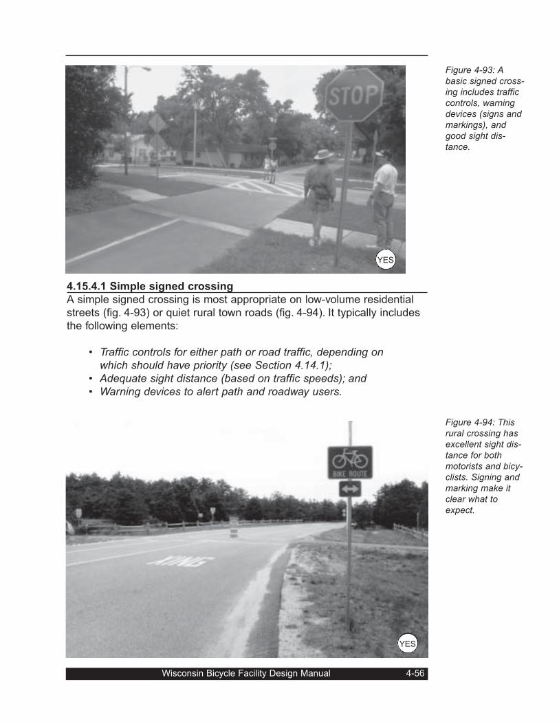
4.15.4.1 Simple signed crossing
A simple signed crossing is most appropriate on low-volume residential
streets (fig. 4-93) or quiet rural town roads (fig. 4-94). It typically includes
the following elements:
• Traffic controls for either path or road traffic, depending onwhich should have priority (see Section 4.14.1);
• Adequate sight distance (based on traffic speeds); and• Warning devices to alert path and roadway users.
Wisconsin Bicycle Facility Design Manual 4-56
Figure 4-93: Abasic signed cross-ing includes trafficcontrols, warningdevices (signs andmarkings), andgood sight dis-tance.
Figure 4-94: Thisrural crossing hasexcellent sight dis-tance for bothmotorists and bicy-clists. Signing andmarking make itclear what toexpect.
YES
YES
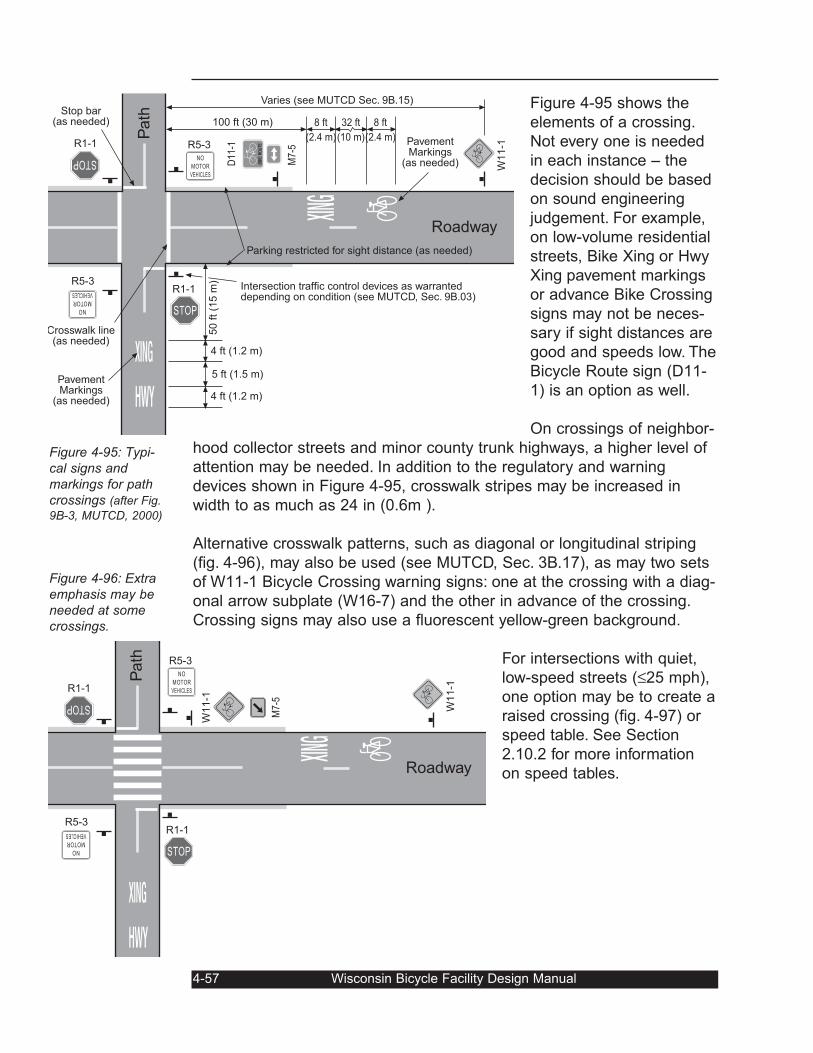
Figure 4-95 shows the
elements of a crossing.
Not every one is needed
in each instance – the
decision should be based
on sound engineering
judgement. For example,
on low-volume residential
streets, Bike Xing or Hwy
Xing pavement markings
or advance Bike Crossing
signs may not be neces-
sary if sight distances are
good and speeds low. The
Bicycle Route sign (D11-
1) is an option as well.
On crossings of neighbor-
hood collector streets and minor county trunk highways, a higher level of
attention may be needed. In addition to the regulatory and warning
devices shown in Figure 4-95, crosswalk stripes may be increased in
width to as much as 24 in (0.6m ).
Alternative crosswalk patterns, such as diagonal or longitudinal striping
(fig. 4-96), may also be used (see MUTCD, Sec. 3B.17), as may two sets
of W11-1 Bicycle Crossing warning signs: one at the crossing with a diag-
onal arrow subplate (W16-7) and the other in advance of the crossing.
Crossing signs may also use a fluorescent yellow-green background.
For intersections with quiet,
low-speed streets (≤25 mph),
one option may be to create a
raised crossing (fig. 4-97) or
speed table. See Section
2.10.2 for more information
on speed tables.
4-57 Wisconsin Bicycle Facility Design Manual
Figure 4-95: Typi-cal signs andmarkings for pathcrossings (after Fig.
9B-3, MUTCD, 2000)
Figure 4-96: Extraemphasis may beneeded at somecrossings.
STOP
STOP
NO
MOTOR
VEHICLES
NO
MOTOR
VEHICLES
Roadway
R1-1
R1-1
R5-3
R5-3
W11-1
Path
M7-
5
W11-1
STOP
STOP
NO
MOTOR
VEHICLES
NO
MOTOR
VEHICLES
BIKE ROU
TE
Roadway
Intersection traffic control devices as warranteddepending on condition (see MUTCD, Sec. 9B.03)
50 ft (1
5 m
)
4 ft (1.2 m)
5 ft (1.5 m)
4 ft (1.2 m)
R1-1
R1-1
R5-3
R5-3
W11-1
100 ft (30 m)
Varies (see MUTCD Sec. 9B.15)
8 ft
(2.4 m)
8 ft
(2.4 m)
32 ft
(10 m)
Crosswalk line(as needed)
D11
-1
Parking restricted for sight distance (as needed)
PavementMarkings
(as needed)
PavementMarkings
(as needed)
Stop bar(as needed)
M7-
5
Path
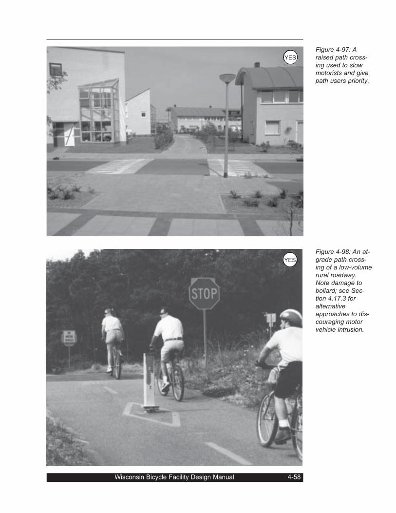
Wisconsin Bicycle Facility Design Manual 4-58
Figure 4-97: Araised path cross-ing used to slowmotorists and givepath users priority.
Figure 4-98: An at-grade path cross-ing of a low-volumerural roadway.Note damage tobollard; see Sec-tion 4.17.3 foralternativeapproaches to dis-couraging motorvehicle intrusion.
YES
YES
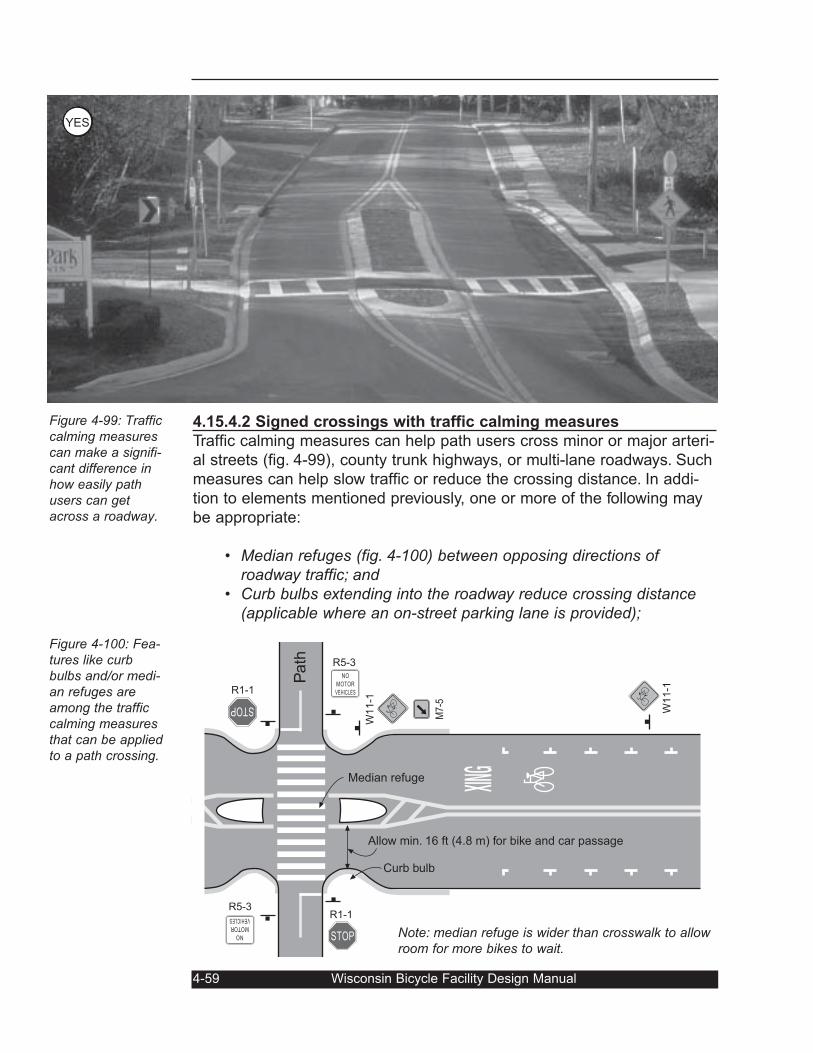
4.15.4.2 Signed crossings with traffic calming measures
Traffic calming measures can help path users cross minor or major arteri-
al streets (fig. 4-99), county trunk highways, or multi-lane roadways. Such
measures can help slow traffic or reduce the crossing distance. In addi-
tion to elements mentioned previously, one or more of the following may
be appropriate:
• Median refuges (fig. 4-100) between opposing directions ofroadway traffic; and
• Curb bulbs extending into the roadway reduce crossing distance(applicable where an on-street parking lane is provided);
4-59 Wisconsin Bicycle Facility Design Manual
Figure 4-99: Trafficcalming measurescan make a signifi-cant difference inhow easily pathusers can getacross a roadway.
Figure 4-100: Fea-tures like curbbulbs and/or medi-an refuges areamong the trafficcalming measuresthat can be appliedto a path crossing.
STOP
STOP
NO
MOTOR
VEHICLES
NO
MOTOR
VEHICLES
R1-1
R1-1
R5-3
R5-3W
11-1
Path
M7-
5
W11-1
Allow min. 16 ft (4.8 m) for bike and car passage
Curb bulb
Median refuge
Note: median refuge is wider than crosswalk to allowroom for more bikes to wait.
YES
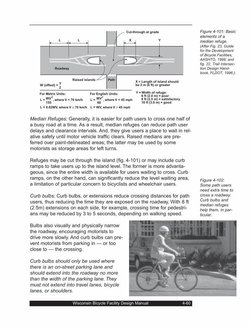
Median Refuges: Generally, it is easier for path users to cross one half of
a busy road at a time. As a result, median refuges can reduce path user
delays and clearance intervals. And, they give users a place to wait in rel-
ative safety until motor vehicle traffic clears. Raised medians are pre-
ferred over paint-delineated areas; the latter may be used by some
motorists as storage areas for left turns.
Refuges may be cut through the island (fig. 4-101) or may include curb
ramps to take users up to the island level. The former is more advanta-
geous, since the entire width is available for users waiting to cross. Curb
ramps, on the other hand, can significantly reduce the level waiting area,
a limitation of particular concern to bicyclists and wheelchair users.
Curb bulbs: Curb bulbs, or extensions reduce crossing distances for path
users, thus reducing the time they are exposed on the roadway, With 8 ft
(2.5m) extensions on each side, for example, crossing time for pedestri-
ans may be reduced by 3 to 5 seconds, depending on walking speed.
Bulbs also visually and physically narrow
the roadway, encouraging motorists to
drive more slowly. And curb bulbs can pre-
vent motorists from parking in — or too
close to — the crossing.
Curb bulbs should only be used wherethere is an on-street parking lane andshould extend into the roadway no morethan the width of the parking lane. Theymust not extend into travel lanes, bicyclelanes, or shoulders.
Wisconsin Bicycle Facility Design Manual 4-60
Figure 4-101: Basicelements of amedian refuge.(After Fig. 23, Guidefor the Developmentof Bicycle Facilities,AASHTO, 1999; andfig. 22, Trail Intersec-tion Design Hand-book, FLDOT, 1996.).
Figure 4-102:Some path usersneed extra time tocross a roadway.Curb bulbs andmedian refugeshelp them, in par-ticular.
Roadway
PathRaised islands
Cut-through at grade
L L X Y
X = Length of island shouldbe 2 m (6 ft) or greater
Y = Width of refuge: 6 ft (2.0 m) = poor 8 ft (2.5 m) = satisfactory 10 ft (3.0 m) = good
W (offset) =Y
2
For Metric Units:
WV
155
2
L =
L = 0.62WV, where V ≥ 70 km/h
, where V < 70 km/h
For English Units:
WV
60
2
L =
L = WV, where V ≥ 45 mph
, where V < 45 mph
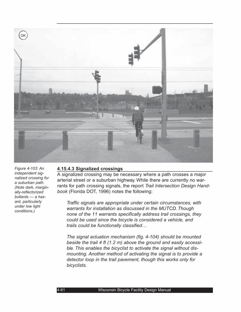
4.15.4.3 Signalized crossings
A signalized crossing may be necessary where a path crosses a major
arterial street or a suburban highway. While there are currently no war-
rants for path crossing signals, the report Trail Intersection Design Hand-book (Florida DOT, 1996) notes the following:
Traffic signals are appropriate under certain circumstances, withwarrants for installation as discussed in the MUTCD. Thoughnone of the 11 warrants specifically address trail crossings, theycould be used since the bicycle is considered a vehicle, andtrails could be functionally classified…
The signal actuation mechanism (fig. 4-104) should be mountedbeside the trail 4 ft (1.2 m) above the ground and easily accessi-ble. This enables the bicyclist to activate the signal without dis-mounting. Another method of activating the signal is to provide adetector loop in the trail pavement, though this works only forbicyclists.
4-61 Wisconsin Bicycle Facility Design Manual
Figure 4-103: Anindependent sig-nalized crossing fora suburban path.(Note dark, margin-ally-reflectorizedbollards — a haz-ard, particularlyunder low light conditions.)
OK
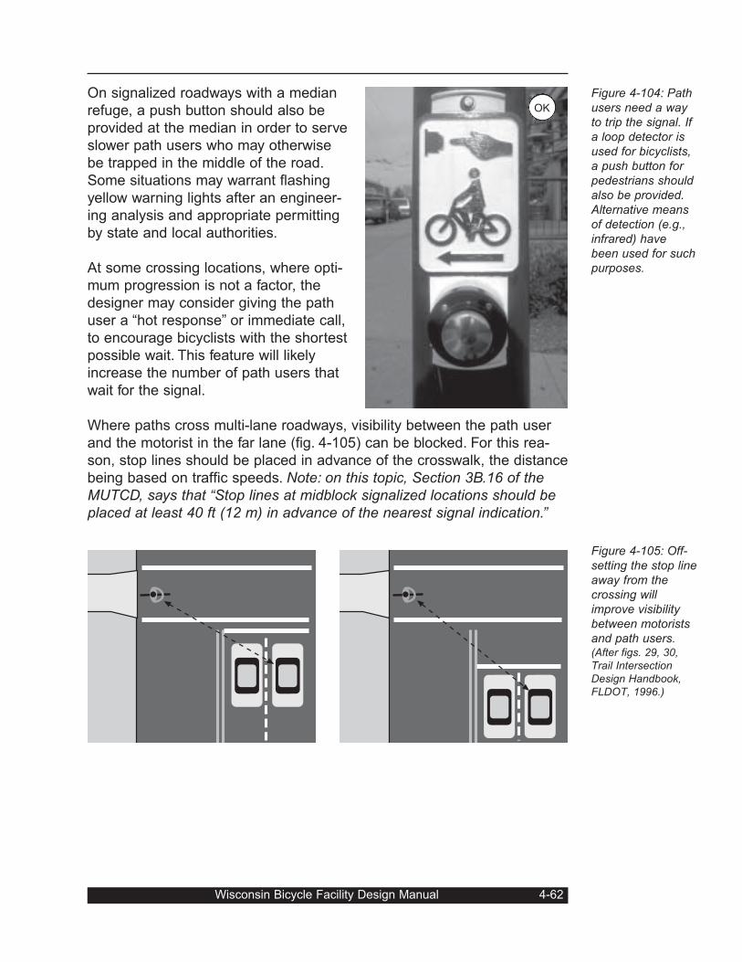
On signalized roadways with a median
refuge, a push button should also be
provided at the median in order to serve
slower path users who may otherwise
be trapped in the middle of the road.
Some situations may warrant flashing
yellow warning lights after an engineer-
ing analysis and appropriate permitting
by state and local authorities.
At some crossing locations, where opti-
mum progression is not a factor, the
designer may consider giving the path
user a “hot response” or immediate call,
to encourage bicyclists with the shortest
possible wait. This feature will likely
increase the number of path users that
wait for the signal.
Where paths cross multi-lane roadways, visibility between the path user
and the motorist in the far lane (fig. 4-105) can be blocked. For this rea-
son, stop lines should be placed in advance of the crosswalk, the distance
being based on traffic speeds. Note: on this topic, Section 3B.16 of theMUTCD, says that “Stop lines at midblock signalized locations should beplaced at least 40 ft (12 m) in advance of the nearest signal indication.”
Wisconsin Bicycle Facility Design Manual 4-62
Figure 4-104: Pathusers need a wayto trip the signal. Ifa loop detector isused for bicyclists,a push button forpedestrians shouldalso be provided.Alternative meansof detection (e.g.,infrared) havebeen used for suchpurposes.
Figure 4-105: Off-setting the stop lineaway from thecrossing willimprove visibilitybetween motoristsand path users.(After figs. 29, 30,Trail IntersectionDesign Handbook,FLDOT, 1996.)
OK
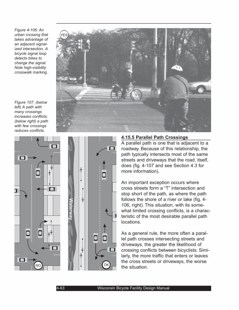
4.15.5 Parallel Path Crossings
A parallel path is one that is adjacent to a
roadway. Because of this relationship, the
path typically intersects most of the same
streets and driveways that the road, itself,
does (fig. 4-107 and see Section 4.3 for
more information).
An important exception occurs where
cross streets form a “T” intersection and
stop short of the path, as where the path
follows the shore of a river or lake (fig. 4-
106, right). This situation, with its some-
what limited crossing conflicts, is a charac-
teristic of the most desirable parallel path
locations.
As a general rule, the more often a paral-
lel path crosses intersecting streets and
driveways, the greater the likelihood of
crossing conflicts between bicyclists. Simi-
larly, the more traffic that enters or leaves
the cross streets or driveways, the worse
the situation.
4-63 Wisconsin Bicycle Facility Design Manual
Figure 4-106: Anurban crossing thattakes advantage ofan adjacent signal-ized intersection. Abicycle signal loopdetects bikes tochange the signal.Note high-visibilitycrosswalk marking.
Figure 107: (belowleft) A path withmany crossingsincreases conflicts;(below right) a pathwith few crossingsreduces conflicts.
Wate
rway
NO OK
YES
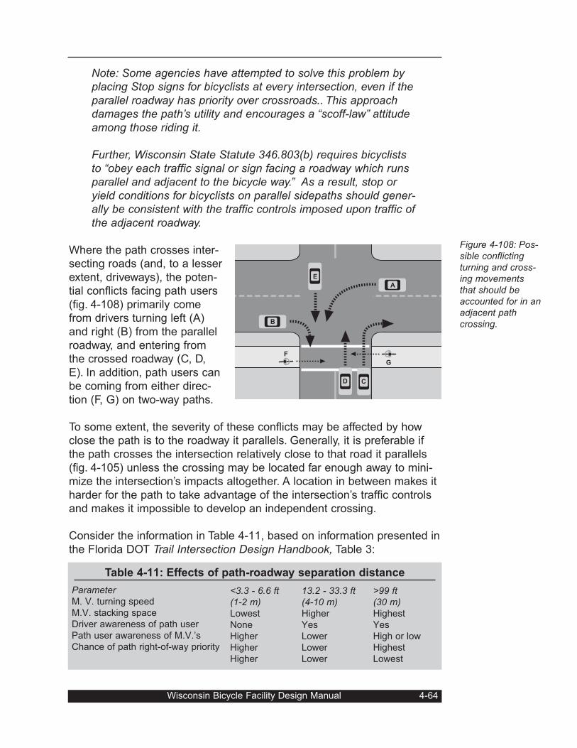
Note: Some agencies have attempted to solve this problem byplacing Stop signs for bicyclists at every intersection, even if theparallel roadway has priority over crossroads.. This approachdamages the path’s utility and encourages a “scoff-law” attitudeamong those riding it.
Further, Wisconsin State Statute 346.803(b) requires bicycliststo “obey each traffic signal or sign facing a roadway which runsparallel and adjacent to the bicycle way.” As a result, stop oryield conditions for bicyclists on parallel sidepaths should gener-ally be consistent with the traffic controls imposed upon traffic ofthe adjacent roadway.
Where the path crosses inter-
secting roads (and, to a lesser
extent, driveways), the poten-
tial conflicts facing path users
(fig. 4-108) primarily come
from drivers turning left (A)
and right (B) from the parallel
roadway, and entering from
the crossed roadway (C, D,
E). In addition, path users can
be coming from either direc-
tion (F, G) on two-way paths.
To some extent, the severity of these conflicts may be affected by how
close the path is to the roadway it parallels. Generally, it is preferable if
the path crosses the intersection relatively close to that road it parallels
(fig. 4-105) unless the crossing may be located far enough away to mini-
mize the intersection’s impacts altogether. A location in between makes it
harder for the path to take advantage of the intersection’s traffic controls
and makes it impossible to develop an independent crossing.
Consider the information in Table 4-11, based on information presented in
the Florida DOT Trail Intersection Design Handbook, Table 3:
Wisconsin Bicycle Facility Design Manual 4-64
Figure 4-108: Pos-sible conflictingturning and cross-ing movementsthat should beaccounted for in anadjacent pathcrossing.
D
B
E
A
C
G
F
ParameterM. V. turning speed
M.V. stacking space
Driver awareness of path user
Path user awareness of M.V.’s
Chance of path right-of-way priority
Table 4-11: Effects of path-roadway separation distance
<3.3 - 6.6 ft (1-2 m)Lowest
None
Higher
Higher
Higher
13.2 - 33.3 ft(4-10 m)Higher
Yes
Lower
Lower
Lower
>99 ft(30 m)Highest
Yes
High or low
Highest
Lowest
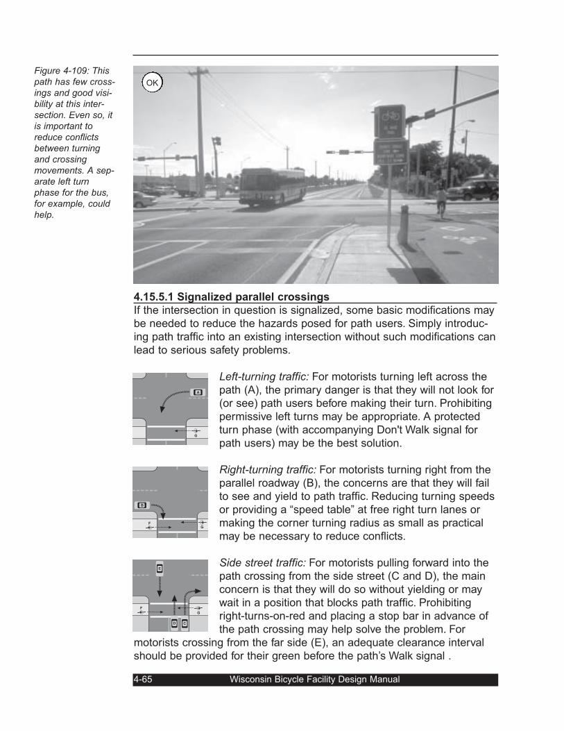
4.15.5.1 Signalized parallel crossings
If the intersection in question is signalized, some basic modifications may
be needed to reduce the hazards posed for path users. Simply introduc-
ing path traffic into an existing intersection without such modifications can
lead to serious safety problems.
Left-turning traffic: For motorists turning left across the
path (A), the primary danger is that they will not look for
(or see) path users before making their turn. Prohibiting
permissive left turns may be appropriate. A protected
turn phase (with accompanying Don't Walk signal for
path users) may be the best solution.
Right-turning traffic: For motorists turning right from the
parallel roadway (B), the concerns are that they will fail
to see and yield to path traffic. Reducing turning speeds
or providing a “speed table” at free right turn lanes or
making the corner turning radius as small as practical
may be necessary to reduce conflicts.
Side street traffic: For motorists pulling forward into the
path crossing from the side street (C and D), the main
concern is that they will do so without yielding or may
wait in a position that blocks path traffic. Prohibiting
right-turns-on-red and placing a stop bar in advance of
the path crossing may help solve the problem. For
motorists crossing from the far side (E), an adequate clearance interval
should be provided for their green before the path’s Walk signal .
4-65 Wisconsin Bicycle Facility Design Manual
Figure 4-109: Thispath has few cross-ings and good visi-bility at this inter-section. Even so, itis important toreduce conflictsbetween turningand crossingmovements. A sep-arate left turnphase for the bus,for example, couldhelp.
A
G
B
FG
D C
G
F
E
OK
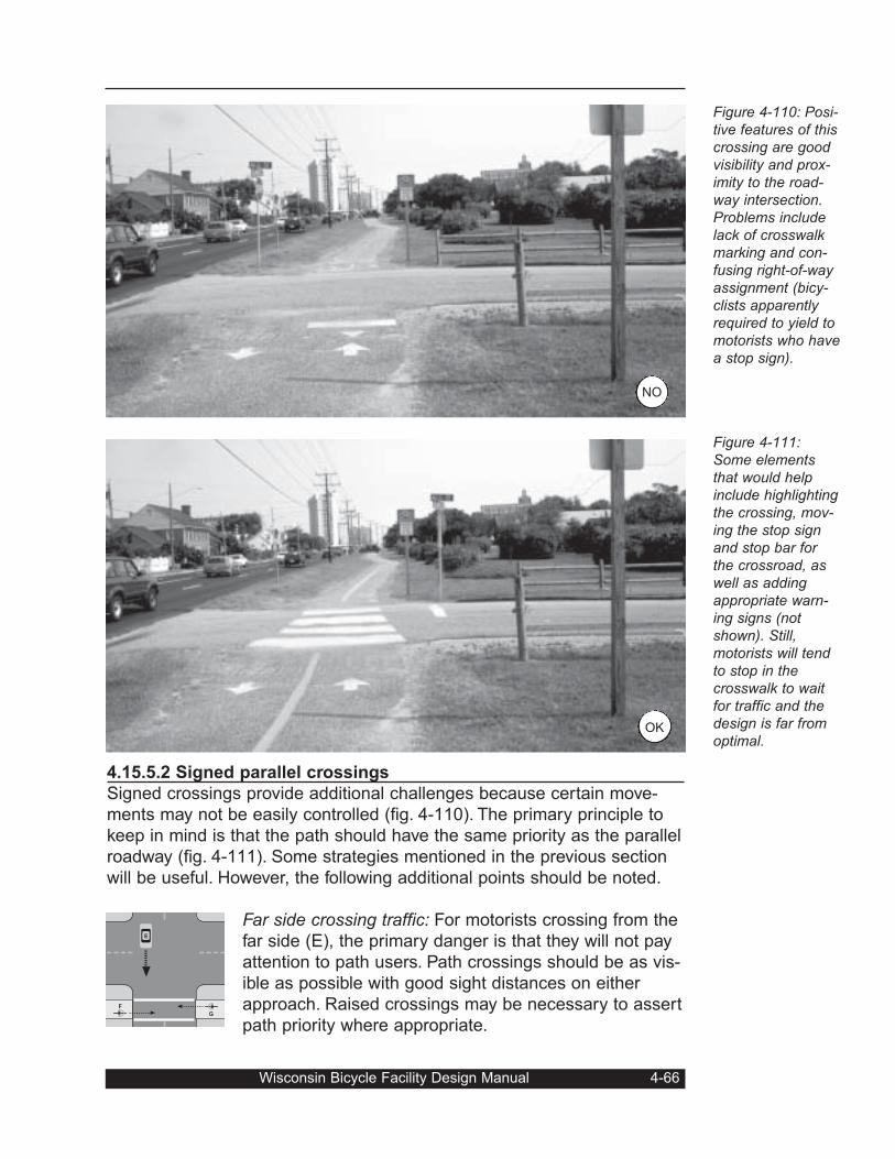
4.15.5.2 Signed parallel crossings
Signed crossings provide additional challenges because certain move-
ments may not be easily controlled (fig. 4-110). The primary principle to
keep in mind is that the path should have the same priority as the parallel
roadway (fig. 4-111). Some strategies mentioned in the previous section
will be useful. However, the following additional points should be noted.
Far side crossing traffic: For motorists crossing from the
far side (E), the primary danger is that they will not pay
attention to path users. Path crossings should be as vis-
ible as possible with good sight distances on either
approach. Raised crossings may be necessary to assert
path priority where appropriate.
Wisconsin Bicycle Facility Design Manual 4-66
Figure 4-110: Posi-tive features of thiscrossing are goodvisibility and prox-imity to the road-way intersection.Problems includelack of crosswalkmarking and con-fusing right-of-wayassignment (bicy-clists apparentlyrequired to yield tomotorists who havea stop sign).
Figure 4-111:Some elementsthat would helpinclude highlightingthe crossing, mov-ing the stop signand stop bar forthe crossroad, aswell as addingappropriate warn-ing signs (notshown). Still,motorists will tendto stop in thecrosswalk to waitfor traffic and thedesign is far fromoptimal.
E
G
F
OK
NO
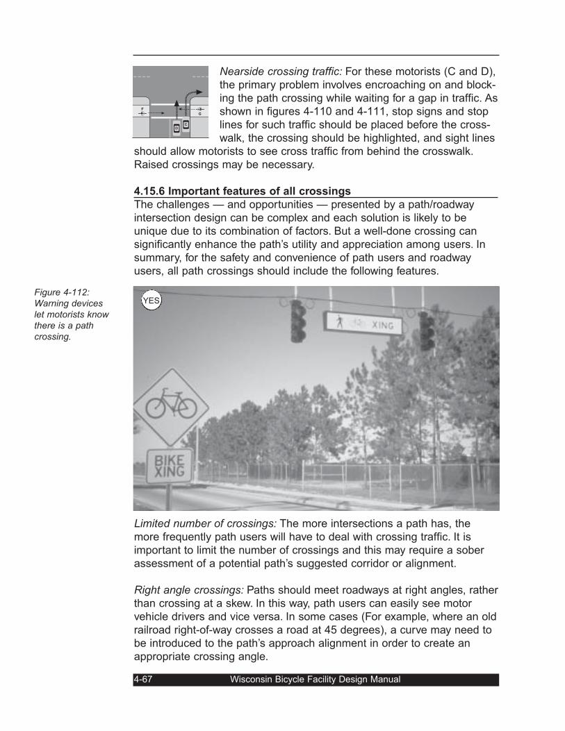
Nearside crossing traffic: For these motorists (C and D),
the primary problem involves encroaching on and block-
ing the path crossing while waiting for a gap in traffic. As
shown in figures 4-110 and 4-111, stop signs and stop
lines for such traffic should be placed before the cross-
walk, the crossing should be highlighted, and sight lines
should allow motorists to see cross traffic from behind the crosswalk.
Raised crossings may be necessary.
4.15.6 Important features of all crossings
The challenges — and opportunities — presented by a path/roadway
intersection design can be complex and each solution is likely to be
unique due to its combination of factors. But a well-done crossing can
significantly enhance the path’s utility and appreciation among users. In
summary, for the safety and convenience of path users and roadway
users, all path crossings should include the following features.
Limited number of crossings: The more intersections a path has, the
more frequently path users will have to deal with crossing traffic. It is
important to limit the number of crossings and this may require a sober
assessment of a potential path’s suggested corridor or alignment.
Right angle crossings: Paths should meet roadways at right angles, rather
than crossing at a skew. In this way, path users can easily see motor
vehicle drivers and vice versa. In some cases (For example, where an old
railroad right-of-way crosses a road at 45 degrees), a curve may need to
be introduced to the path’s approach alignment in order to create an
appropriate crossing angle.
4-67 Wisconsin Bicycle Facility Design Manual
Figure 4-112:Warning deviceslet motorists knowthere is a pathcrossing.
C
G
F
D
YES
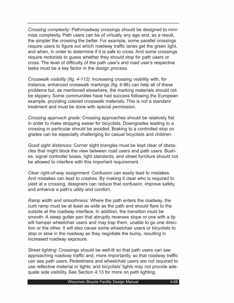
Crossing complexity: Path/roadway crossings should be designed to mini-
mize complexity. Path users can be of virtually any age and, as a result,
the simpler the crossing the better. For example, some parallel crossings
require users to figure out which roadway traffic lanes get the green light,
and when, in order to determine if it is safe to cross. And some crossings
require motorists to guess whether they should stop for path users or
cross. The level of difficulty of the path user’s and road user’s respective
tasks must be a key factor in the design process.
Crosswalk visibility (fig. 4-112): Increasing crossing visibility with, for
instance, enhanced crosswalk markings (fig. 4-96) can help all of these
problems but, as mentioned elsewhere, the marking materials should not
be slippery. Some communities have had success following the European
example, providing colored crosswalk materials. This is not a standard
treatment and must be done with special permission.
Crossing approach grade: Crossing approaches should be relatively flat
in order to make stopping easier for bicyclists. Downgrades leading to a
crossing in particular should be avoided. Braking to a controlled stop on
grades can be especially challenging for casual bicyclists and children.
Good sight distances: Corner sight triangles must be kept clear of obsta-
cles that might block the view between road users and path users. Bush-
es, signal controller boxes, light standards, and street furniture should not
be allowed to interfere with this important requirement.
Clear right-of-way assignment: Confusion can easily lead to mistakes.
And mistakes can lead to crashes. By making it clear who is required to
yield at a crossing, designers can reduce that confusion, improve safety,
and enhance a path’s utility and comfort.
Ramp width and smoothness: Where the path enters the roadway, the
curb ramp must be at least as wide as the path and should flare to the
outside at the roadway interface. In addition, the transition must be
smooth. A steep gutter pan that abruptly reverses slope or one with a lip
will hamper wheelchair users and may trap them, unable to go one direc-
tion or the other. It will also cause some wheelchair users or bicyclists to
stop or slow in the roadway as they negotiate the bump, resulting in
increased roadway exposure.
Street lighting: Crossings should be well-lit so that path users can see
approaching roadway traffic and, more importantly, so that roadway traffic
can see path users. Pedestrians and wheelchair users are not required to
use reflective material or lights; and bicyclists’ lights may not provide ade-
quate side visibility. See Section 4.13 for more on path lighting.
Wisconsin Bicycle Facility Design Manual 4-68
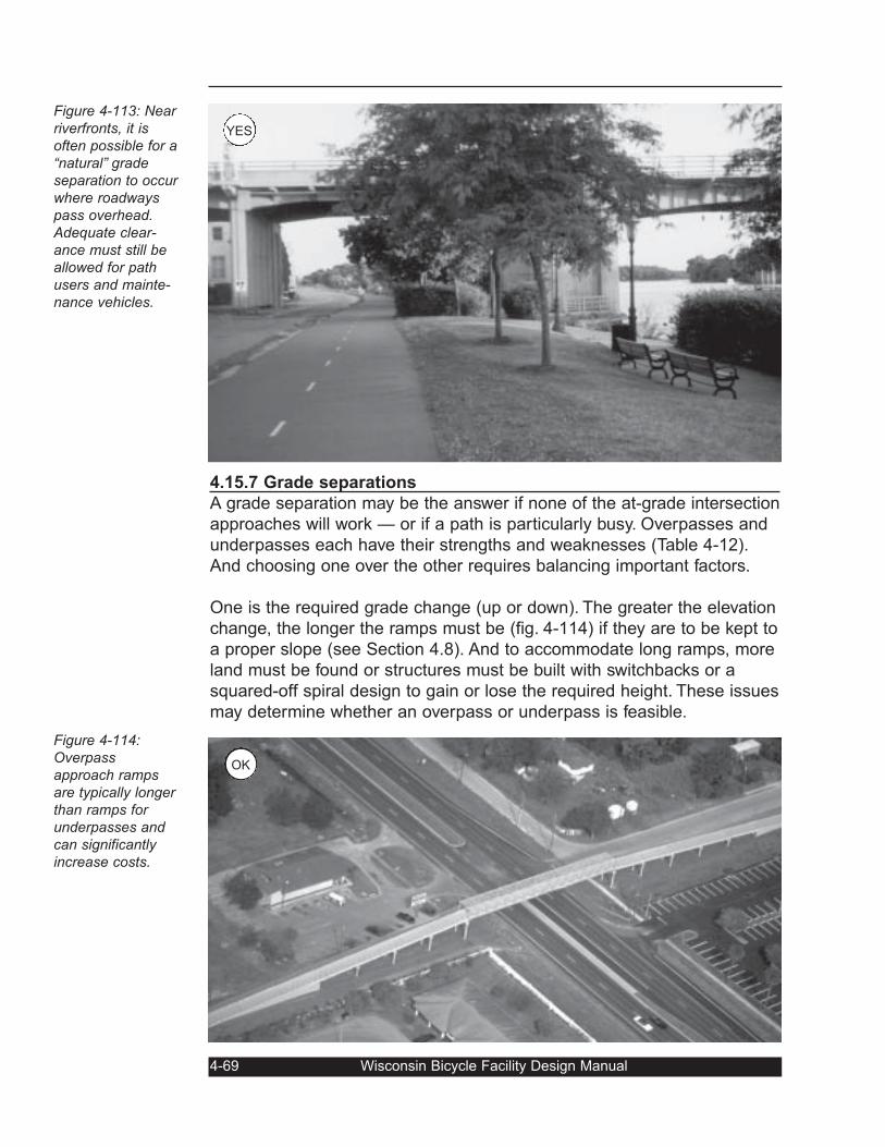
4.15.7 Grade separations
A grade separation may be the answer if none of the at-grade intersection
approaches will work — or if a path is particularly busy. Overpasses and
underpasses each have their strengths and weaknesses (Table 4-12).
And choosing one over the other requires balancing important factors.
One is the required grade change (up or down). The greater the elevation
change, the longer the ramps must be (fig. 4-114) if they are to be kept to
a proper slope (see Section 4.8). And to accommodate long ramps, more
land must be found or structures must be built with switchbacks or a
squared-off spiral design to gain or lose the required height. These issues
may determine whether an overpass or underpass is feasible.
4-69 Wisconsin Bicycle Facility Design Manual
Figure 4-113: Nearriverfronts, it isoften possible for a“natural” gradeseparation to occurwhere roadwayspass overhead.Adequate clear-ance must still beallowed for pathusers and mainte-nance vehicles.
Figure 4-114:Overpassapproach rampsare typically longerthan ramps forunderpasses andcan significantlyincrease costs.
OK
YES
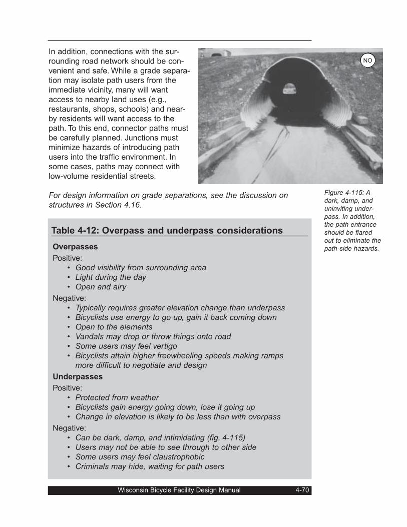
In addition, connections with the sur-
rounding road network should be con-
venient and safe. While a grade separa-
tion may isolate path users from the
immediate vicinity, many will want
access to nearby land uses (e.g.,
restaurants, shops, schools) and near-
by residents will want access to the
path. To this end, connector paths must
be carefully planned. Junctions must
minimize hazards of introducing path
users into the traffic environment. In
some cases, paths may connect with
low-volume residential streets.
For design information on grade separations, see the discussion onstructures in Section 4.16.
Wisconsin Bicycle Facility Design Manual 4-70
Figure 4-115: Adark, damp, anduninviting under-pass. In addition,the path entranceshould be flaredout to eliminate thepath-side hazards.
Table 4-12: Overpass and underpass considerations
Overpasses
Positive:
• Good visibility from surrounding area• Light during the day• Open and airy
Negative:
• Typically requires greater elevation change than underpass• Bicyclists use energy to go up, gain it back coming down• Open to the elements• Vandals may drop or throw things onto road• Some users may feel vertigo• Bicyclists attain higher freewheeling speeds making ramps
more difficult to negotiate and design
Underpasses
Positive:
• Protected from weather• Bicyclists gain energy going down, lose it going up• Change in elevation is likely to be less than with overpass
Negative:
• Can be dark, damp, and intimidating (fig. 4-115)• Users may not be able to see through to other side• Some users may feel claustrophobic• Criminals may hide, waiting for path users
NO
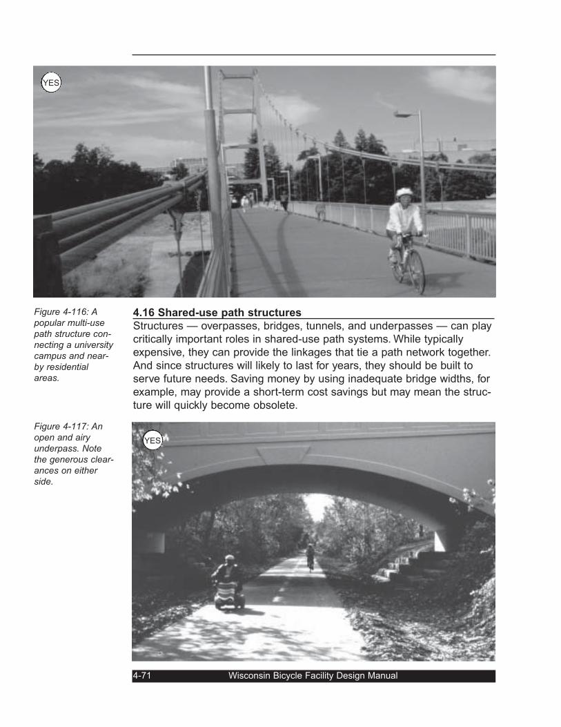
4.16 Shared-use path structures
Structures — overpasses, bridges, tunnels, and underpasses — can play
critically important roles in shared-use path systems. While typically
expensive, they can provide the linkages that tie a path network together.
And since structures will likely to last for years, they should be built to
serve future needs. Saving money by using inadequate bridge widths, for
example, may provide a short-term cost savings but may mean the struc-
ture will quickly become obsolete.
4-71 Wisconsin Bicycle Facility Design Manual
Figure 4-116: Apopular multi-usepath structure con-necting a universitycampus and near-by residentialareas.
Figure 4-117: Anopen and airyunderpass. Notethe generous clear-ances on eitherside.
YES
YES
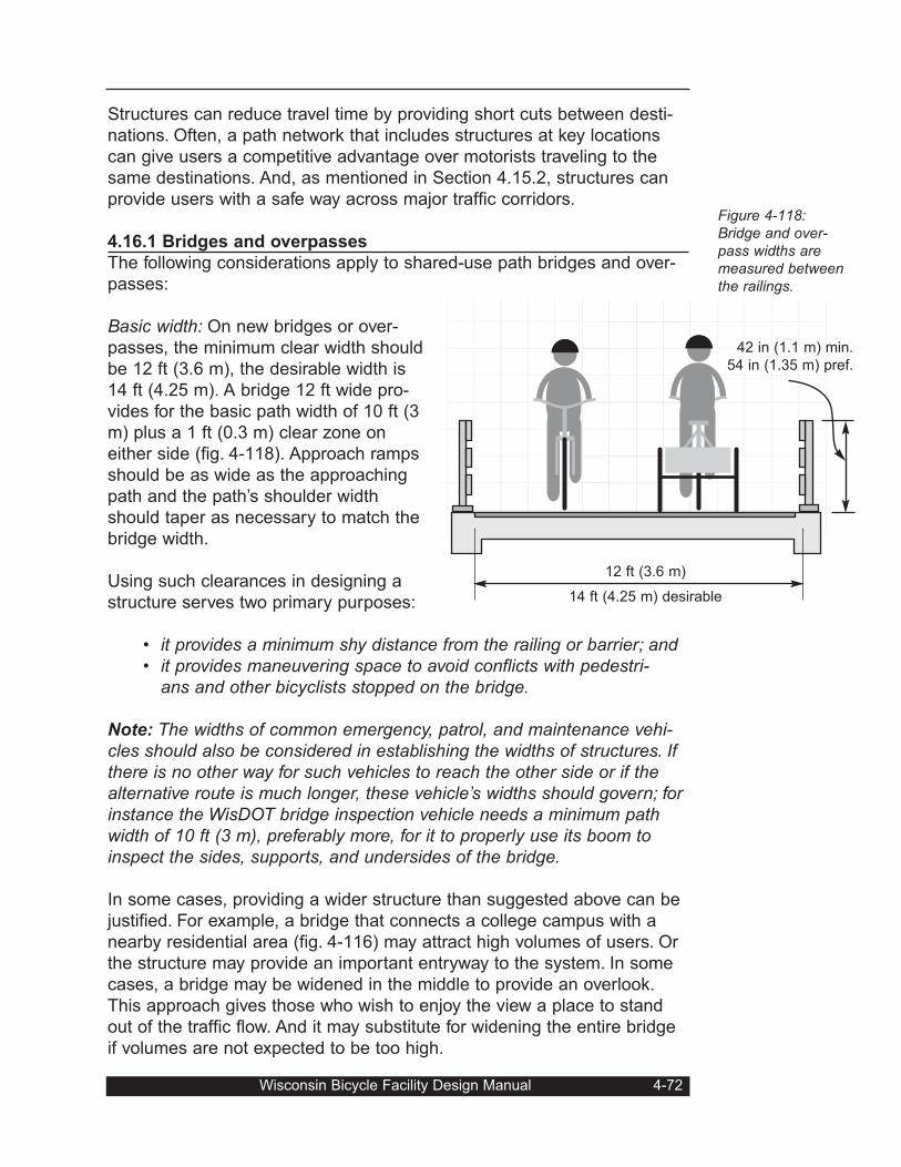
Structures can reduce travel time by providing short cuts between desti-
nations. Often, a path network that includes structures at key locations
can give users a competitive advantage over motorists traveling to the
same destinations. And, as mentioned in Section 4.15.2, structures can
provide users with a safe way across major traffic corridors.
4.16.1 Bridges and overpasses
The following considerations apply to shared-use path bridges and over-
passes:
Basic width: On new bridges or over-
passes, the minimum clear width should
be 12 ft (3.6 m), the desirable width is
14 ft (4.25 m). A bridge 12 ft wide pro-
vides for the basic path width of 10 ft (3
m) plus a 1 ft (0.3 m) clear zone on
either side (fig. 4-118). Approach ramps
should be as wide as the approaching
path and the path’s shoulder width
should taper as necessary to match the
bridge width.
Using such clearances in designing a
structure serves two primary purposes:
• it provides a minimum shy distance from the railing or barrier; and• it provides maneuvering space to avoid conflicts with pedestri-
ans and other bicyclists stopped on the bridge.
Note: The widths of common emergency, patrol, and maintenance vehi-cles should also be considered in establishing the widths of structures. Ifthere is no other way for such vehicles to reach the other side or if thealternative route is much longer, these vehicle’s widths should govern; forinstance the WisDOT bridge inspection vehicle needs a minimum pathwidth of 10 ft (3 m), preferably more, for it to properly use its boom toinspect the sides, supports, and undersides of the bridge.
In some cases, providing a wider structure than suggested above can be
justified. For example, a bridge that connects a college campus with a
nearby residential area (fig. 4-116) may attract high volumes of users. Or
the structure may provide an important entryway to the system. In some
cases, a bridge may be widened in the middle to provide an overlook.
This approach gives those who wish to enjoy the view a place to stand
out of the traffic flow. And it may substitute for widening the entire bridge
if volumes are not expected to be too high.
Wisconsin Bicycle Facility Design Manual 4-72
Figure 4-118:Bridge and over-pass widths aremeasured betweenthe railings.
12 ft (3.6 m)
14 ft (4.25 m) desirable
42 in (1.1 m) min.
54 in (1.35 m) pref.
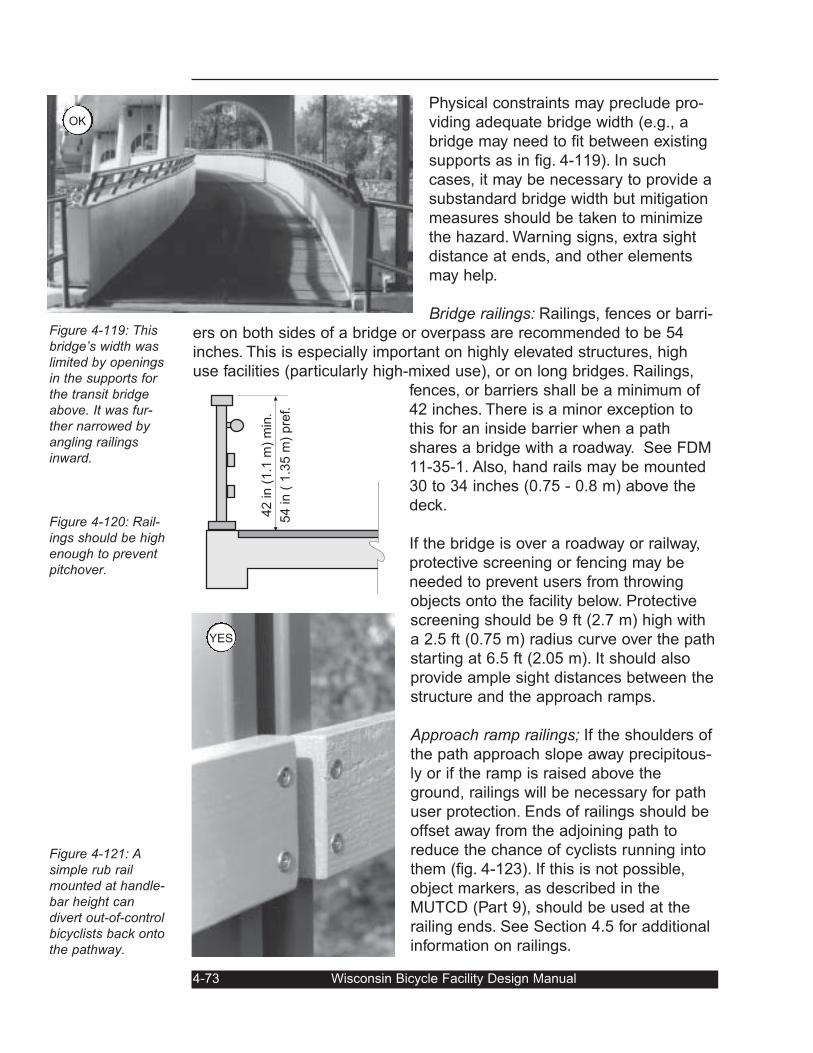
Physical constraints may preclude pro-
viding adequate bridge width (e.g., a
bridge may need to fit between existing
supports as in fig. 4-119). In such
cases, it may be necessary to provide a
substandard bridge width but mitigation
measures should be taken to minimize
the hazard. Warning signs, extra sight
distance at ends, and other elements
may help.
Bridge railings: Railings, fences or barri-
ers on both sides of a bridge or overpass are recommended to be 54
inches. This is especially important on highly elevated structures, high
use facilities (particularly high-mixed use), or on long bridges. Railings,
fences, or barriers shall be a minimum of
42 inches. There is a minor exception to
this for an inside barrier when a path
shares a bridge with a roadway. See FDM
11-35-1. Also, hand rails may be mounted
30 to 34 inches (0.75 - 0.8 m) above the
deck.
If the bridge is over a roadway or railway,
protective screening or fencing may be
needed to prevent users from throwing
objects onto the facility below. Protective
screening should be 9 ft (2.7 m) high with
a 2.5 ft (0.75 m) radius curve over the path
starting at 6.5 ft (2.05 m). It should also
provide ample sight distances between the
structure and the approach ramps.
Approach ramp railings; If the shoulders of
the path approach slope away precipitous-
ly or if the ramp is raised above the
ground, railings will be necessary for path
user protection. Ends of railings should be
offset away from the adjoining path to
reduce the chance of cyclists running into
them (fig. 4-123). If this is not possible,
object markers, as described in the
MUTCD (Part 9), should be used at the
railing ends. See Section 4.5 for additional
information on railings.
4-73 Wisconsin Bicycle Facility Design Manual
Figure 4-119: Thisbridge’s width waslimited by openingsin the supports forthe transit bridgeabove. It was fur-ther narrowed byangling railingsinward.
Figure 4-120: Rail-ings should be highenough to preventpitchover.
Figure 4-121: Asimple rub railmounted at handle-bar height candivert out-of-controlbicyclists back ontothe pathway.
42 in (
1.1
m)
min
.
54 in (
1.3
5 m
) pre
f.
OK
YES
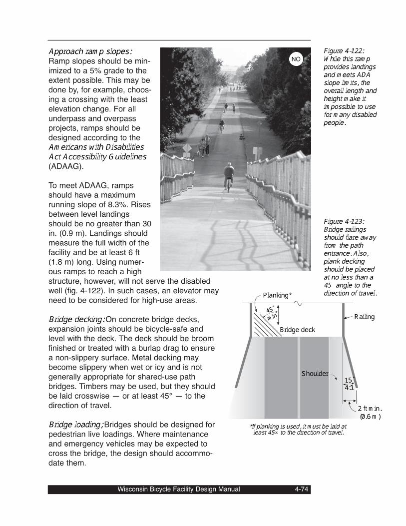
Approach ramp slopes:Ramp slopes should be min-imized to a 5% grade to theextent possible. This may bedone by, for example, choos-ing a crossing with the leastelevation change. For allunderpass and overpassprojects, ramps should bedesigned according to theAmericans with DisabilitiesAct Accessibility Guidelines(ADAAG). To meet ADAAG, rampsshould have a maximumrunning slope of 8.3%. Risesbetween level landingsshould be no greater than 30in. (0.9 m). Landings shouldmeasure the full width of thefacility and be at least 6 ft(1.8 m) long. Using numer-ous ramps to reach a highstructure, however, will not serve the disabledwell (fig. 4-122). In such cases, an elevator mayneed to be considered for high-use areas.Bridge decking: On concrete bridge decks,expansion joints should be bicycle-safe andlevel with the deck. The deck should be broomfinished or treated with a burlap drag to ensurea non-slippery surface. Metal decking maybecome slippery when wet or icy and is notgenerally appropriate for shared-use pathbridges. Timbers may be used, but they shouldbe laid crosswise — or at least 45° — to thedirection of travel. Bridge loading; Bridges should be designed forpedestrian live loadings. Where maintenanceand emergency vehicles may be expected tocross the bridge, the design should accommo-date them.
Wisconsin Bicycle Facility Design Manual 4-74
Bridge deck
Shoulder
2 ft min.(0.6 m)
Railing
15˚
45˚min.
Planking*
*If planking is used, it must be laid atleast 45∞ to the direction of travel.
4:1
Figure 4-122:While this rampprovides landingsand meets ADAslope limits, theoverall length andheight make itimpossible to usefor many disabledpeople.
Figure 4-123:Bridge railingsshould flare awayfrom the pathentrance. Also,plank deckingshould be placedat no less than a45° angle to thedirection of travel.
NO
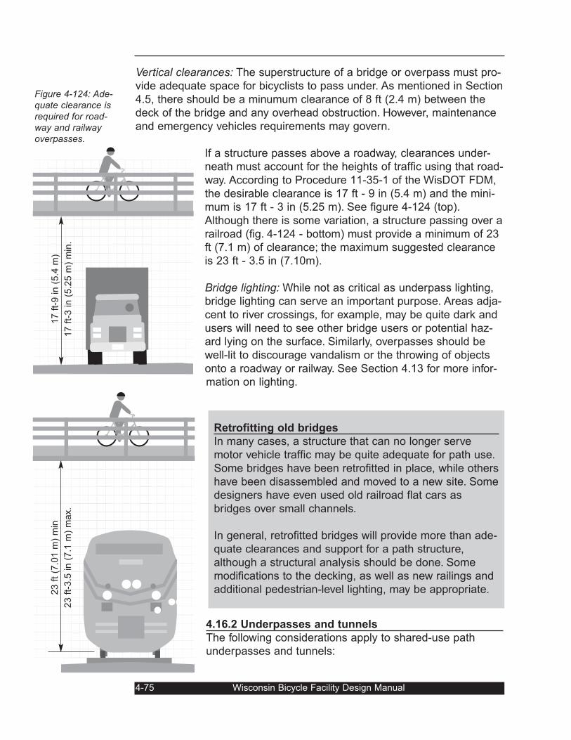
Vertical clearances: The superstructure of a bridge or overpass must pro-
vide adequate space for bicyclists to pass under. As mentioned in Section
4.5, there should be a minumum clearance of 8 ft (2.4 m) between the
deck of the bridge and any overhead obstruction. However, maintenance
and emergency vehicles requirements may govern.
If a structure passes above a roadway, clearances under-
neath must account for the heights of traffic using that road-
way. According to Procedure 11-35-1 of the WisDOT FDM,
the desirable clearance is 17 ft - 9 in (5.4 m) and the mini-
mum is 17 ft - 3 in (5.25 m). See figure 4-124 (top).
Although there is some variation, a structure passing over a
railroad (fig. 4-124 - bottom) must provide a minimum of 23
ft (7.1 m) of clearance; the maximum suggested clearance
is 23 ft - 3.5 in (7.10m).
Bridge lighting: While not as critical as underpass lighting,
bridge lighting can serve an important purpose. Areas adja-
cent to river crossings, for example, may be quite dark and
users will need to see other bridge users or potential haz-
ard lying on the surface. Similarly, overpasses should be
well-lit to discourage vandalism or the throwing of objects
onto a roadway or railway. See Section 4.13 for more infor-
mation on lighting.
4.16.2 Underpasses and tunnels
The following considerations apply to shared-use path
underpasses and tunnels:
4-75 Wisconsin Bicycle Facility Design Manual
Figure 4-124: Ade-quate clearance isrequired for road-way and railwayoverpasses.
17 f
t-9 in (
5.4
m)
17 f
t-3 in (
5.2
5 m
) m
in.
23 f
t (7
.01 m
) m
in
23 f
t-3.5
in (
7.1
m)
max.
Retrofitting old bridges
In many cases, a structure that can no longer serve
motor vehicle traffic may be quite adequate for path use.
Some bridges have been retrofitted in place, while others
have been disassembled and moved to a new site. Some
designers have even used old railroad flat cars as
bridges over small channels.
In general, retrofitted bridges will provide more than ade-
quate clearances and support for a path structure,
although a structural analysis should be done. Some
modifications to the decking, as well as new railings and
additional pedestrian-level lighting, may be appropriate.
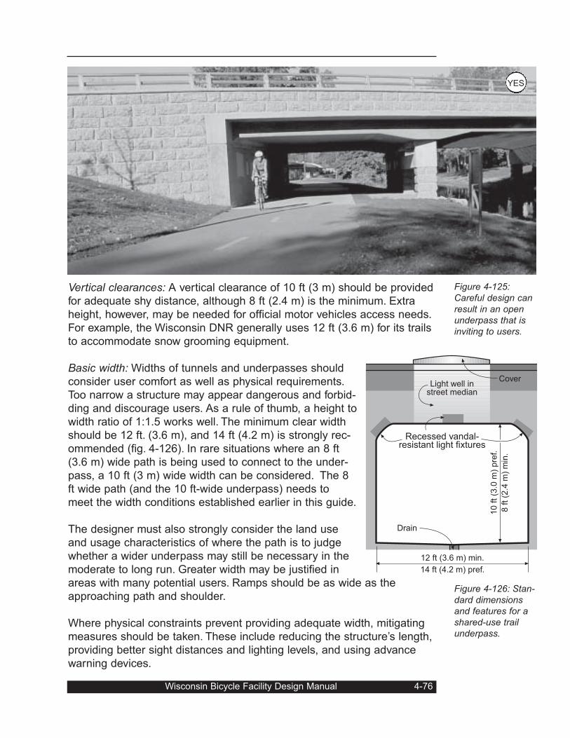
Vertical clearances: A vertical clearance of 10 ft (3 m) should be provided
for adequate shy distance, although 8 ft (2.4 m) is the minimum. Extra
height, however, may be needed for official motor vehicles access needs.
For example, the Wisconsin DNR generally uses 12 ft (3.6 m) for its trails
to accommodate snow grooming equipment.
Basic width: Widths of tunnels and underpasses should
consider user comfort as well as physical requirements.
Too narrow a structure may appear dangerous and forbid-
ding and discourage users. As a rule of thumb, a height to
width ratio of 1:1.5 works well. The minimum clear width
should be 12 ft. (3.6 m), and 14 ft (4.2 m) is strongly rec-
ommended (fig. 4-126). In rare situations where an 8 ft
(3.6 m) wide path is being used to connect to the under-
pass, a 10 ft (3 m) wide width can be considered. The 8
ft wide path (and the 10 ft-wide underpass) needs to
meet the width conditions established earlier in this guide.
The designer must also strongly consider the land use
and usage characteristics of where the path is to judge
whether a wider underpass may still be necessary in the
moderate to long run. Greater width may be justified in
areas with many potential users. Ramps should be as wide as the
approaching path and shoulder.
Where physical constraints prevent providing adequate width, mitigating
measures should be taken. These include reducing the structure’s length,
providing better sight distances and lighting levels, and using advance
warning devices.
Wisconsin Bicycle Facility Design Manual 4-76
Figure 4-125:Careful design canresult in an openunderpass that isinviting to users.
Figure 4-126: Stan-dard dimensionsand features for ashared-use trailunderpass.
Light well instreet median
12 ft (3.6 m) min.
14 ft (4.2 m) pref.
10 ft
(3.0
m)
pre
f.
8 ft (2
.4 m
) m
in.
Recessed vandal-resistant light fixtures
Cover
Drain
YES
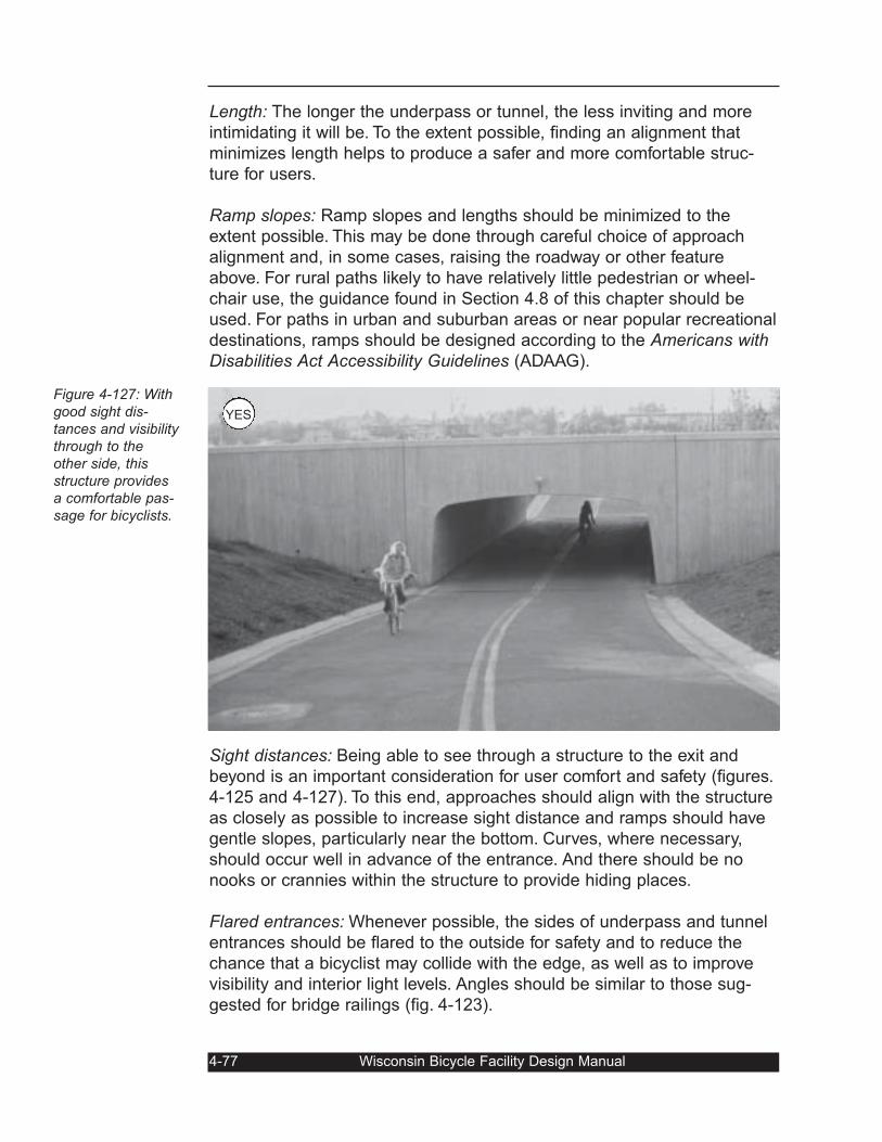
Length: The longer the underpass or tunnel, the less inviting and more
intimidating it will be. To the extent possible, finding an alignment that
minimizes length helps to produce a safer and more comfortable struc-
ture for users.
Ramp slopes: Ramp slopes and lengths should be minimized to the
extent possible. This may be done through careful choice of approach
alignment and, in some cases, raising the roadway or other feature
above. For rural paths likely to have relatively little pedestrian or wheel-
chair use, the guidance found in Section 4.8 of this chapter should be
used. For paths in urban and suburban areas or near popular recreational
destinations, ramps should be designed according to the Americans withDisabilities Act Accessibility Guidelines (ADAAG).
Sight distances: Being able to see through a structure to the exit and
beyond is an important consideration for user comfort and safety (figures.
4-125 and 4-127). To this end, approaches should align with the structure
as closely as possible to increase sight distance and ramps should have
gentle slopes, particularly near the bottom. Curves, where necessary,
should occur well in advance of the entrance. And there should be no
nooks or crannies within the structure to provide hiding places.
Flared entrances: Whenever possible, the sides of underpass and tunnel
entrances should be flared to the outside for safety and to reduce the
chance that a bicyclist may collide with the edge, as well as to improve
visibility and interior light levels. Angles should be similar to those sug-
gested for bridge railings (fig. 4-123).
4-77 Wisconsin Bicycle Facility Design Manual
Figure 4-127: Withgood sight dis-tances and visibilitythrough to theother side, thisstructure providesa comfortable pas-sage for bicyclists.
YES
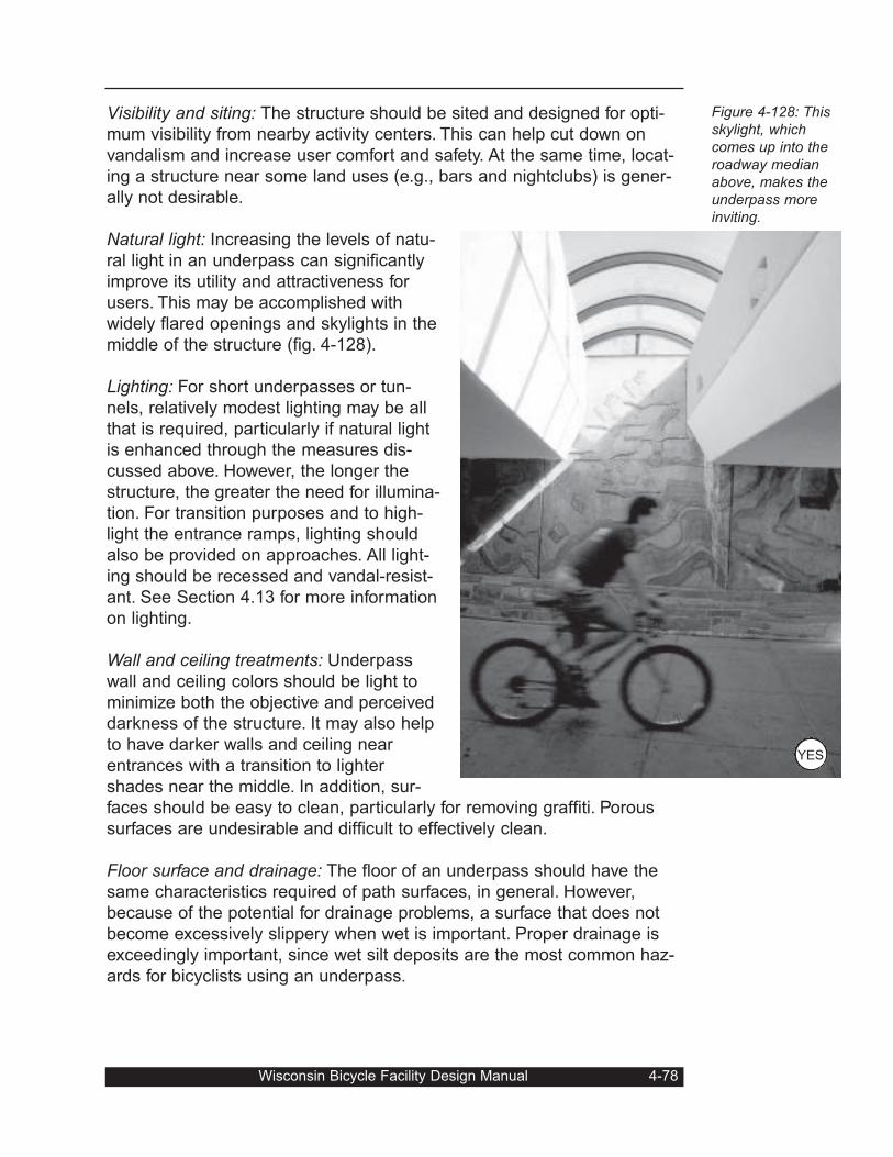
Visibility and siting: The structure should be sited and designed for opti-
mum visibility from nearby activity centers. This can help cut down on
vandalism and increase user comfort and safety. At the same time, locat-
ing a structure near some land uses (e.g., bars and nightclubs) is gener-
ally not desirable.
Natural light: Increasing the levels of natu-
ral light in an underpass can significantly
improve its utility and attractiveness for
users. This may be accomplished with
widely flared openings and skylights in the
middle of the structure (fig. 4-128).
Lighting: For short underpasses or tun-
nels, relatively modest lighting may be all
that is required, particularly if natural light
is enhanced through the measures dis-
cussed above. However, the longer the
structure, the greater the need for illumina-
tion. For transition purposes and to high-
light the entrance ramps, lighting should
also be provided on approaches. All light-
ing should be recessed and vandal-resist-
ant. See Section 4.13 for more information
on lighting.
Wall and ceiling treatments: Underpass
wall and ceiling colors should be light to
minimize both the objective and perceived
darkness of the structure. It may also help
to have darker walls and ceiling near
entrances with a transition to lighter
shades near the middle. In addition, sur-
faces should be easy to clean, particularly for removing graffiti. Porous
surfaces are undesirable and difficult to effectively clean.
Floor surface and drainage: The floor of an underpass should have the
same characteristics required of path surfaces, in general. However,
because of the potential for drainage problems, a surface that does not
become excessively slippery when wet is important. Proper drainage is
exceedingly important, since wet silt deposits are the most common haz-
ards for bicyclists using an underpass.
Wisconsin Bicycle Facility Design Manual 4-78
Figure 4-128: Thisskylight, whichcomes up into theroadway medianabove, makes theunderpass moreinviting.
YES
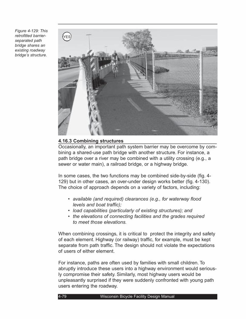
4.16.3 Combining structures
Occasionally, an important path system barrier may be overcome by com-
bining a shared-use path bridge with another structure. For instance, a
path bridge over a river may be combined with a utility crossing (e.g., a
sewer or water main), a railroad bridge, or a highway bridge.
In some cases, the two functions may be combined side-by-side (fig. 4-
129) but in other cases, an over-under design works better (fig. 4-130).
The choice of approach depends on a variety of factors, including:
• available (and required) clearances (e.g., for waterway floodlevels and boat traffic);
• load capabilities (particularly of existing structures); and• the elevations of connecting facilities and the grades required
to meet those elevations.
When combining crossings, it is critical to protect the integrity and safety
of each element. Highway (or railway) traffic, for example, must be kept
separate from path traffic. The design should not violate the expectations
of users of either element.
For instance, paths are often used by families with small children. To
abruptly introduce these users into a highway environment would serious-
ly compromise their safety. Similarly, most highway users would be
unpleasantly surprised if they were suddenly confronted with young path
users entering the roadway.
4-79 Wisconsin Bicycle Facility Design Manual
Figure 4-129: Thisretrofitted barrier-separated pathbridge shares anexisting roadwaybridge’s structure.
YES
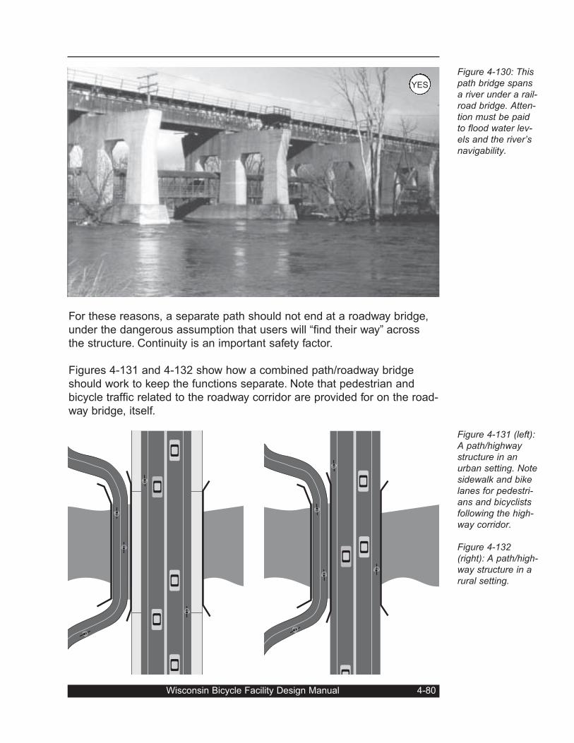
For these reasons, a separate path should not end at a roadway bridge,
under the dangerous assumption that users will “find their way” across
the structure. Continuity is an important safety factor.
Figures 4-131 and 4-132 show how a combined path/roadway bridge
should work to keep the functions separate. Note that pedestrian and
bicycle traffic related to the roadway corridor are provided for on the road-
way bridge, itself.
Wisconsin Bicycle Facility Design Manual 4-80
Figure 4-130: Thispath bridge spansa river under a rail-road bridge. Atten-tion must be paidto flood water lev-els and the river’snavigability.
Figure 4-131 (left):A path/highwaystructure in anurban setting. Notesidewalk and bikelanes for pedestri-ans and bicyclistsfollowing the high-way corridor.
Figure 4-132(right): A path/high-way structure in arural setting.
YES
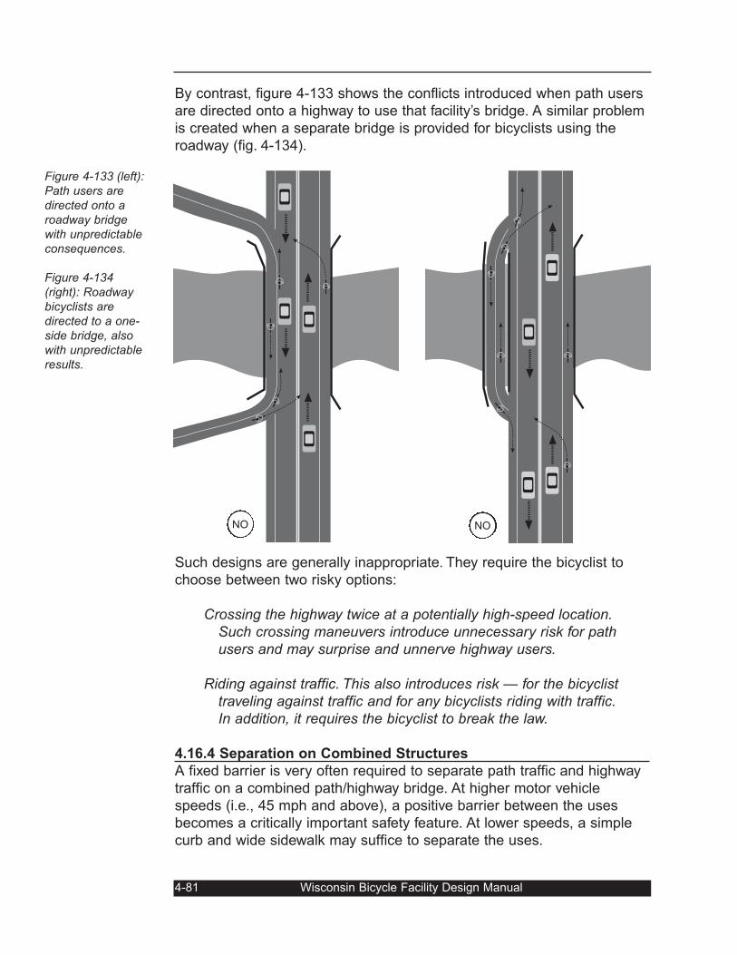
By contrast, figure 4-133 shows the conflicts introduced when path users
are directed onto a highway to use that facility’s bridge. A similar problem
is created when a separate bridge is provided for bicyclists using the
roadway (fig. 4-134).
Such designs are generally inappropriate. They require the bicyclist to
choose between two risky options:
Crossing the highway twice at a potentially high-speed location.Such crossing maneuvers introduce unnecessary risk for pathusers and may surprise and unnerve highway users.
Riding against traffic. This also introduces risk — for the bicyclisttraveling against traffic and for any bicyclists riding with traffic.In addition, it requires the bicyclist to break the law.
4.16.4 Separation on Combined Structures
A fixed barrier is very often required to separate path traffic and highway
traffic on a combined path/highway bridge. At higher motor vehicle
speeds (i.e., 45 mph and above), a positive barrier between the uses
becomes a critically important safety feature. At lower speeds, a simple
curb and wide sidewalk may suffice to separate the uses.
4-81 Wisconsin Bicycle Facility Design Manual
Figure 4-133 (left):Path users aredirected onto aroadway bridgewith unpredictableconsequences.
Figure 4-134(right): Roadwaybicyclists aredirected to a one-side bridge, alsowith unpredictableresults.
NONO
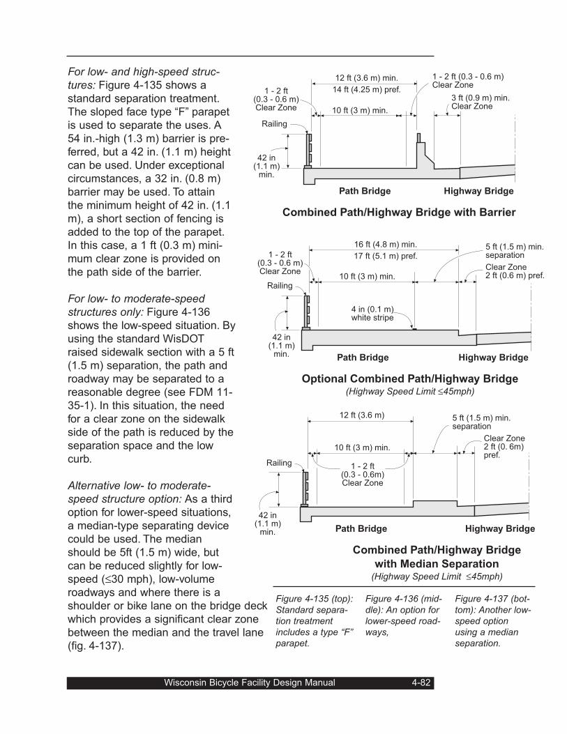
For low- and high-speed struc-tures: Figure 4-135 shows a
standard separation treatment.
The sloped face type “F” parapet
is used to separate the uses. A
54 in.-high (1.3 m) barrier is pre-
ferred, but a 42 in. (1.1 m) height
can be used. Under exceptional
circumstances, a 32 in. (0.8 m)
barrier may be used. To attain
the minimum height of 42 in. (1.1
m), a short section of fencing is
added to the top of the parapet.
In this case, a 1 ft (0.3 m) mini-
mum clear zone is provided on
the path side of the barrier.
For low- to moderate-speedstructures only: Figure 4-136
shows the low-speed situation. By
using the standard WisDOT
raised sidewalk section with a 5 ft
(1.5 m) separation, the path and
roadway may be separated to a
reasonable degree (see FDM 11-
35-1). In this situation, the need
for a clear zone on the sidewalk
side of the path is reduced by the
separation space and the low
curb.
Alternative low- to moderate-speed structure option: As a third
option for lower-speed situations,
a median-type separating device
could be used. The median
should be 5ft (1.5 m) wide, but
can be reduced slightly for low-
speed (≤30 mph), low-volume
roadways and where there is a
shoulder or bike lane on the bridge deck
which provides a significant clear zone
between the median and the travel lane
(fig. 4-137).
Wisconsin Bicycle Facility Design Manual 4-82
Highway Bridge
10 ft (3 m) min.
42 in(1.1 m)
min.
Railing
17 ft (5.1 m) pref.
16 ft (4.8 m) min.
Path Bridge
Clear Zone2 ft (0.6 m) pref.
5 ft (1.5 m) min.separation
Optional Combined Path/Highway Bridge(Highway Speed Limit ≤45mph)
4 in (0.1 m)white stripe
1 - 2 ft(0.3 - 0.6 m)Clear Zone
Highway Bridge
10 ft (3 m) min.
Railing
12 ft (3.6 m)
Path Bridge
Clear Zone2 ft (0. 6m)pref.
5 ft (1.5 m) min.separation
Combined Path/Highway Bridge
with Median Separation(Highway Speed Limit ≤45mph)
42 in(1.1 m)
min.
1 - 2 ft(0.3 - 0.6m)Clear Zone
42 in(1.1 m)
min.
Highway Bridge
1 - 2 ft(0.3 - 0.6 m)Clear Zone 10 ft (3 m) min.
Railing
14 ft (4.25 m) pref.
12 ft (3.6 m) min.
Path Bridge
3 ft (0.9 m) min.Clear Zone
Combined Path/Highway Bridge with Barrier
1 - 2 ft (0.3 - 0.6 m)Clear Zone
Figure 4-135 (top):Standard separa-tion treatmentincludes a type “F”parapet.
Figure 4-136 (mid-dle): An option forlower-speed road-ways,
Figure 4-137 (bot-tom): Another low-speed optionusing a medianseparation.
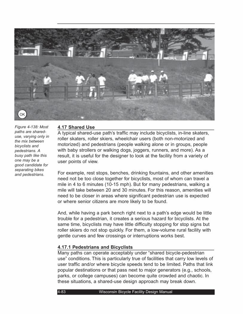
4.17 Shared Use
A typical shared-use path’s traffic may include bicyclists, in-line skaters,
roller skaters, roller skiers, wheelchair users (both non-motorized and
motorized) and pedestrians (people walking alone or in groups, people
with baby strollers or walking dogs, joggers, runners, and more). As a
result, it is useful for the designer to look at the facility from a variety of
user points of view.
For example, rest stops, benches, drinking fountains, and other amenities
need not be too close together for bicyclists, most of whom can travel a
mile in 4 to 6 minutes (10-15 mph). But for many pedestrians, walking a
mile will take between 20 and 30 minutes. For this reason, amenities will
need to be closer in areas where significant pedestrian use is expected
or where senior citizens are more likely to be found.
And, while having a park bench right next to a path’s edge would be little
trouble for a pedestrian, it creates a serious hazard for bicyclists. At the
same time, bicyclists may have little difficulty stopping for stop signs but
roller skiers do not stop quickly. For them, a low-volume rural facility with
gentle curves and few crossings or interruptions works best.
4.17.1 Pedestrians and Bicyclists
Many paths can operate acceptably under “shared bicycle-pedestrian
use” conditions. This is particularly true of facilities that carry low levels of
user traffic and/or where bicycle speeds tend to be limited. Paths that link
popular destinations or that pass next to major generators (e.g., schools,
parks, or college campuses) can become quite crowded and chaotic. In
these situations, a shared-use design approach may break down.
4-83 Wisconsin Bicycle Facility Design Manual
Figure 4-138: Mostpaths are shared-use, varying only inthe mix betweenbicyclists andpedestrians. Abusy path like thisone may be agood candidate forseparating bikesand pedestrians.
OK
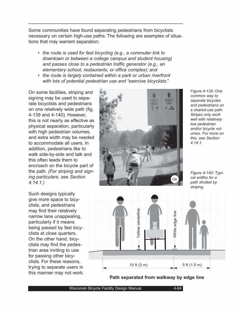
Some communities have found separating pedestrians from bicyclists
necessary on certain high-use paths. The following are examples of situa-
tions that may warrant separation:
• the route is used for fast bicycling (e.g., a commuter link todowntown or between a college campus and student housing)and passes close to a pedestrian traffic generator (e.g., anelementary school, restaurants, or office complex); and
• the route is largely contained within a park or urban riverfrontwith lots of potential pedestrian use and “exercise bicyclists.”
On some facilities, striping and
signing may be used to sepa-
rate bicyclists and pedestrians
on one relatively wide path (fig.
4-139 and 4-140). However,
this is not nearly as effective as
physical separation, particularly
with high pedestrian volumes,
and extra width may be needed
to accommodate all users. In
addition, pedestrians like to
walk side-by-side and talk and
this often leads them to
encroach on the bicycle part of
the path. (For striping and sign-ing particulars, see Section4.14.1.)
Such designs typically
give more space to bicy-
clists, and pedestrians
may find their relatively
narrow lane unappealing,
particularly if it means
being passed by fast bicy-
clists at close quarters.
On the other hand, bicy-
clists may find the pedes-
trian area inviting to use
for passing other bicy-
clists. For these reasons,
trying to separate users in
this manner may not work.
Wisconsin Bicycle Facility Design Manual 4-84
Figure 4-139: Onecommon way toseparate bicyclesand pedestrians ona shared-use path.Stripes only workwell with relativelylow pedestrianand/or bicycle vol-umes. For more onthis, see Section4.14.1.
Figure 4-140: Typi-cal widths for apath divided bystriping.
Path separated from walkway by edge line
5 ft (1.5 m)10 ft (3 m)
Yello
w c
ente
rlin
e
White e
dge lin
eOK
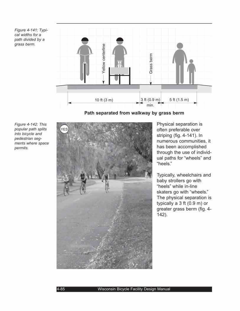
Physical separation is
often preferable over
striping (fig. 4-141). In
numerous communities, it
has been accomplished
through the use of individ-
ual paths for “wheels” and
“heels.”
Typically, wheelchairs and
baby strollers go with
“heels” while in-line
skaters go with “wheels.”
The physical separation is
typically a 3 ft (0.9 m) or
greater grass berm (fig. 4-
142).
4-85 Wisconsin Bicycle Facility Design Manual
Figure 4-141: Typi-cal widths for apath divided by agrass berm.
Figure 4-142: Thispopular path splitsinto bicycle andpedestrian seg-ments where spacepermits.
Path separated from walkway by grass berm
5 ft (1.5 m)3 ft (0.9 m)
min.
10 ft (3 m)Y
ello
w c
ente
rlin
e
Gra
ss b
erm
YES
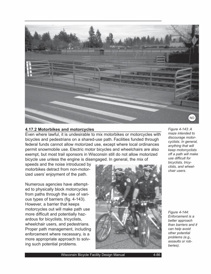
4.17.2 Motorbikes and motorcycles
Even where lawful, it is undesirable to mix motorbikes or motorcycles with
bicycles and pedestrians on a shared-use path. Facilities funded through
federal funds cannot allow motorized use, except where local ordinances
permit snowmobile use. Electric motor bicycles and wheelchairs are also
exempt, but most trail sponsors in Wisconsin still do not allow motorized
bicycle use unless the engine is disengaged. In general, the mix of
speeds and the noise introduced by
motorbikes detract from non-motor-
ized users’ enjoyment of the path.
Numerous agencies have attempt-
ed to physically block motorcycles
from paths through the use of vari-
ous types of barriers (fig. 4-143).
However, a barrier that keeps
motorcycles out will make path use
more difficult and potentially haz-
ardous for bicyclists, tricyclists,
wheelchair users, and pedestrians.
Proper path management, including
enforcement where necessary, is a
more appropriate approach to solv-
ing such potential problems.
Wisconsin Bicycle Facility Design Manual 4-86
Figure 4-143: Amaze intended todiscourage motor-cyclists. In general,anything that willkeep motorcyclistsoff a path will makeuse difficult forbicyclists, tricy-clists, and wheel-chair users.
Figure 4-144:Enforcement is abetter approachthan barriers and itcan help avoidother potentialproblems (e.g.,assaults or rob-beries).
NO
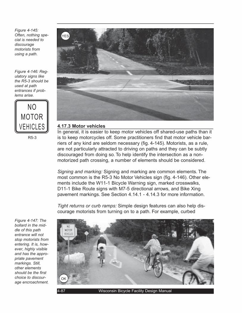
4.17.3 Motor vehicles
In general, it is easier to keep motor vehicles off shared-use paths than it
is to keep motorcycles off. Some practitioners find that motor vehicle bar-
riers of any kind are seldom necessary (fig. 4-145). Motorists, as a rule,
are not particularly attracted to driving on paths and they can be subtly
discouraged from doing so. To help identify the intersection as a non-
motorized path crossing, a number of elements should be considered.
Signing and marking: Signing and marking are common elements. The
most common is the R5-3 No Motor Vehicles sign (fig. 4-146). Other ele-
ments include the W11-1 Bicycle Warning sign, marked crosswalks,
D11-1 Bike Route signs with M7-5 directional arrows, and Bike Xing
pavement markings. See Section 4.14.1 - 4.14.3 for more information.
Tight returns or curb ramps: Simple design features can also help dis-
courage motorists from turning on to a path. For example, curbed
4-87 Wisconsin Bicycle Facility Design Manual
Figure 4-145:Often, nothing spe-cial is needed todiscouragemotorists fromusing a path.
Figure 4-146: Reg-ulatory signs likethe R5-3 should beused at pathentrances if prob-lems arise.
Figure 4-147: Thebollard in the mid-dle of this pathentrance will notstop motorists fromentering. It is, how-ever, highly visibleand has the appro-priate pavementmarkings. Still,other elementsshould be the firstchoice to discour-age encroachment.
NO
MOTOR
VEHICLES
R5-3
OK
YES
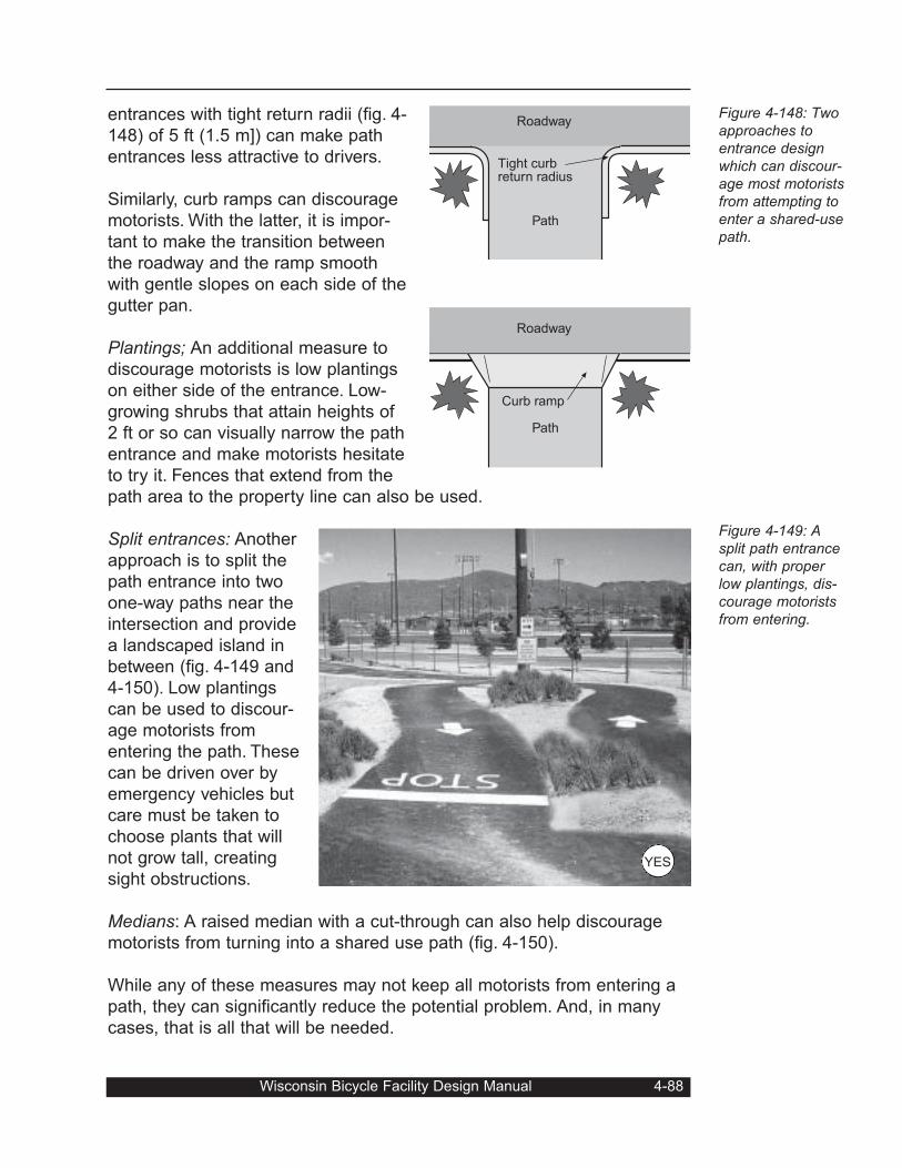
entrances with tight return radii (fig. 4-
148) of 5 ft (1.5 m]) can make path
entrances less attractive to drivers.
Similarly, curb ramps can discourage
motorists. With the latter, it is impor-
tant to make the transition between
the roadway and the ramp smooth
with gentle slopes on each side of the
gutter pan.
Plantings; An additional measure to
discourage motorists is low plantings
on either side of the entrance. Low-
growing shrubs that attain heights of
2 ft or so can visually narrow the path
entrance and make motorists hesitate
to try it. Fences that extend from the
path area to the property line can also be used.
Split entrances: Another
approach is to split the
path entrance into two
one-way paths near the
intersection and provide
a landscaped island in
between (fig. 4-149 and
4-150). Low plantings
can be used to discour-
age motorists from
entering the path. These
can be driven over by
emergency vehicles but
care must be taken to
choose plants that will
not grow tall, creating
sight obstructions.
Medians: A raised median with a cut-through can also help discourage
motorists from turning into a shared use path (fig. 4-150).
While any of these measures may not keep all motorists from entering a
path, they can significantly reduce the potential problem. And, in many
cases, that is all that will be needed.
Wisconsin Bicycle Facility Design Manual 4-88
Figure 4-148: Twoapproaches toentrance designwhich can discour-age most motoristsfrom attempting toenter a shared-usepath.
Figure 4-149: Asplit path entrancecan, with properlow plantings, dis-courage motoristsfrom entering.
Tight curbreturn radius
Roadway
Path
Curb ramp
Path
Roadway
YES
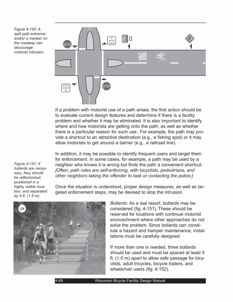
If a problem with motorist use of a path arises, the first action should be
to evaluate current design features and determine if there is a facility
problem and whether it may be eliminated. It is also important to identify
where and how motorists are getting onto the path, as well as whether
there is a particular reason for such use.. For example, the path may pro-
vide a shortcut to an attractive destination (e.g., a fishing spot) or it may
allow motorists to get around a barrier (e.g., a railroad line).
In addition, it may be possible to identify frequent users and target them
for enforcement. In some cases, for example, a path may be used by a
neighbor who knows it is wrong but finds the path a convenient shortcut.
[Often, path rules are self-enforcing, with bicyclists, pedestrians, andother neighbors taking the offender to task or contacting the police.]
Once the situation is understood, proper design measures, as well as tar-
geted enforcement steps, may be devised to stop the intrusion.
Bollards: As a last resort, bollards may be
considered (fig. 4-151). These should be
reserved for locations with continual motorist
encroachment where other approaches do not
solve the problem. Since bollards can consti-
tute a hazard and hamper maintenance, instal-
lations must be carefully designed.
If more than one is needed, three bollards
should be used and must be spaced at least 5
ft. (1.5 m) apart to allow safe passage for bicy-
clists, adult tricycles, bicycle trailers, and
wheelchair users (fig. 4-152).
4-89 Wisconsin Bicycle Facility Design Manual
Figure 4-150: Asplit path entranceand/or a median onthe roadway candiscouragemotorist intrusion.
Figure 4-151: Ifbollards are neces-sary, they shouldbe reflectorized,positioned in ahighly visible loca-tion, and separatedby 5 ft. (1.5 m).
STOP
STOP
NO
MOTOR
VEHICLES
NO
MOTOR
VEHICLES
BIKE ROU
TE
OK
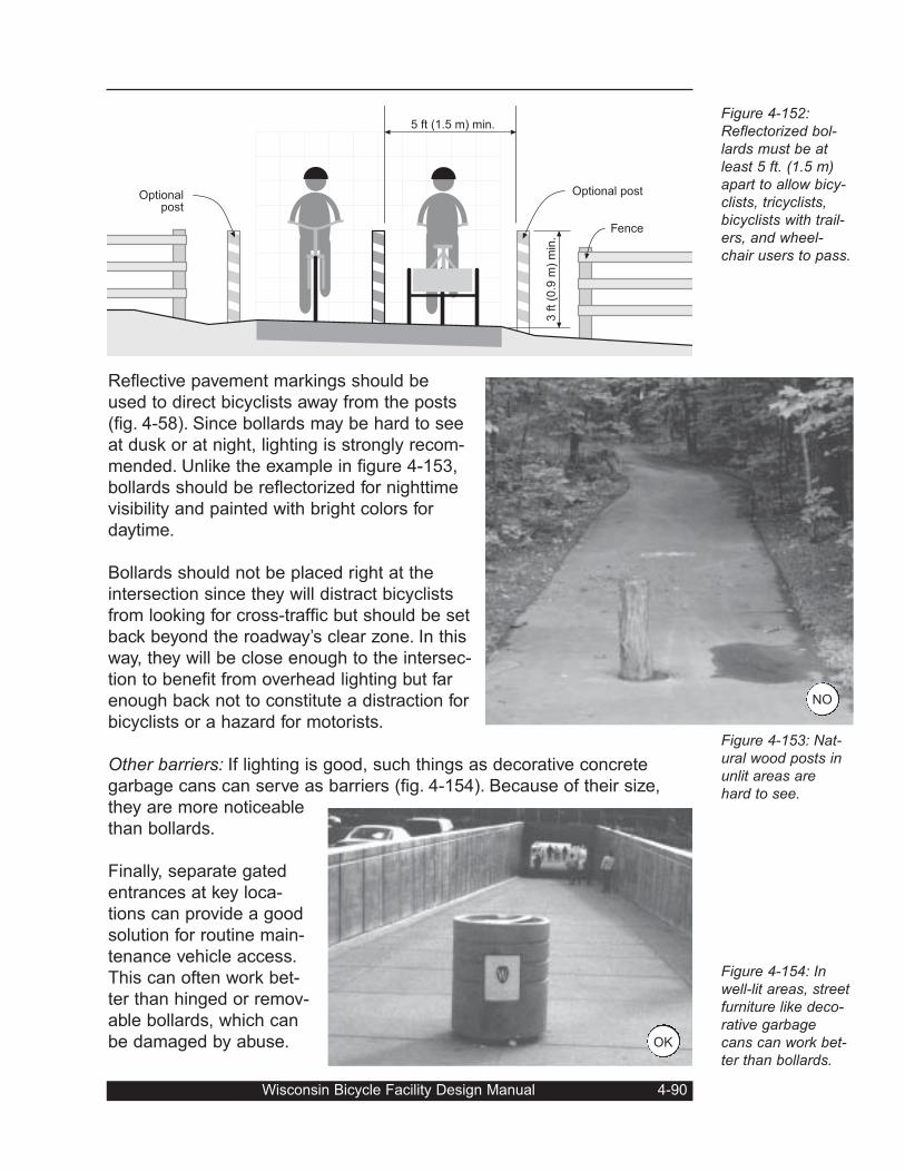
Reflective pavement markings should be
used to direct bicyclists away from the posts
(fig. 4-58). Since bollards may be hard to see
at dusk or at night, lighting is strongly recom-
mended. Unlike the example in figure 4-153,
bollards should be reflectorized for nighttime
visibility and painted with bright colors for
daytime.
Bollards should not be placed right at the
intersection since they will distract bicyclists
from looking for cross-traffic but should be set
back beyond the roadway’s clear zone. In this
way, they will be close enough to the intersec-
tion to benefit from overhead lighting but far
enough back not to constitute a distraction for
bicyclists or a hazard for motorists.
Other barriers: If lighting is good, such things as decorative concrete
garbage cans can serve as barriers (fig. 4-154). Because of their size,
they are more noticeable
than bollards.
Finally, separate gated
entrances at key loca-
tions can provide a good
solution for routine main-
tenance vehicle access.
This can often work bet-
ter than hinged or remov-
able bollards, which can
be damaged by abuse.
Wisconsin Bicycle Facility Design Manual 4-90
Figure 4-152:Reflectorized bol-lards must be atleast 5 ft. (1.5 m)apart to allow bicy-clists, tricyclists,bicyclists with trail-ers, and wheel-chair users to pass.
Figure 4-153: Nat-ural wood posts inunlit areas arehard to see.
Figure 4-154: Inwell-lit areas, streetfurniture like deco-rative garbagecans can work bet-ter than bollards.
5 ft (1.5 m) min.
3 ft (0
.9 m
) m
in.
Optional post
Fence
Optionalpost
OK
NO
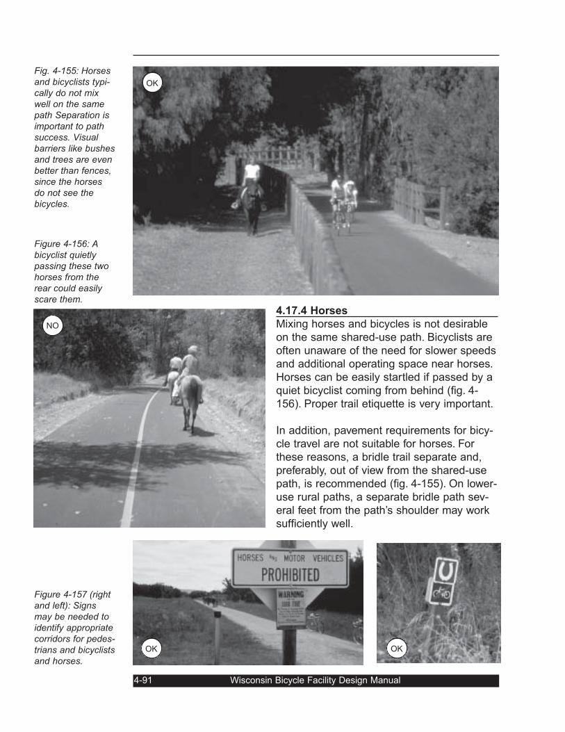
4.17.4 Horses
Mixing horses and bicycles is not desirable
on the same shared-use path. Bicyclists are
often unaware of the need for slower speeds
and additional operating space near horses.
Horses can be easily startled if passed by a
quiet bicyclist coming from behind (fig. 4-
156). Proper trail etiquette is very important.
In addition, pavement requirements for bicy-
cle travel are not suitable for horses. For
these reasons, a bridle trail separate and,
preferably, out of view from the shared-use
path, is recommended (fig. 4-155). On lower-
use rural paths, a separate bridle path sev-
eral feet from the path’s shoulder may work
sufficiently well.
4-91 Wisconsin Bicycle Facility Design Manual
Fig. 4-155: Horsesand bicyclists typi-cally do not mixwell on the samepath Separation isimportant to pathsuccess. Visualbarriers like bushesand trees are evenbetter than fences,since the horsesdo not see thebicycles.
Figure 4-156: Abicyclist quietlypassing these twohorses from therear could easilyscare them.
Figure 4-157 (rightand left): Signsmay be needed toidentify appropriatecorridors for pedes-trians and bicyclistsand horses.
OK
OK OK
NO
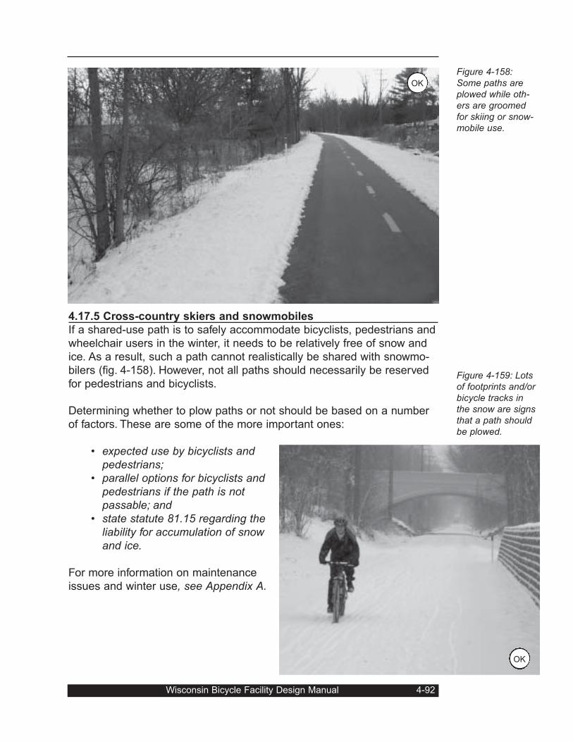
4.17.5 Cross-country skiers and snowmobiles
If a shared-use path is to safely accommodate bicyclists, pedestrians and
wheelchair users in the winter, it needs to be relatively free of snow and
ice. As a result, such a path cannot realistically be shared with snowmo-
bilers (fig. 4-158). However, not all paths should necessarily be reserved
for pedestrians and bicyclists.
Determining whether to plow paths or not should be based on a number
of factors. These are some of the more important ones:
• expected use by bicyclists andpedestrians;
• parallel options for bicyclists andpedestrians if the path is notpassable; and
• state statute 81.15 regarding theliability for accumulation of snowand ice.
For more information on maintenance
issues and winter use, see Appendix A.
Wisconsin Bicycle Facility Design Manual 4-92
Figure 4-158:Some paths areplowed while oth-ers are groomedfor skiing or snow-mobile use.
Figure 4-159: Lotsof footprints and/orbicycle tracks inthe snow are signsthat a path shouldbe plowed.
OK
OK
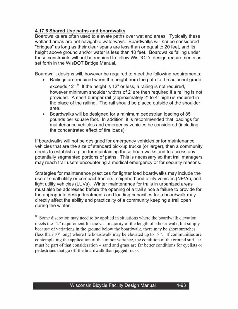
4.17.6 Shared Use paths and boardwalks Boardwalks are often used to elevate paths over wetland areas. Typically these wetland areas are not navigable waterways. Boardwalks will not be considered "bridges" as long as their clear spans are less than or equal to 20 feet, and its height above ground and/or water is less than 10 feet. Boardwalks falling under these constraints will not be required to follow WisDOT's design requirements as set forth in the WisDOT Bridge Manual.
Boardwalk designs will, however be required to meet the following requirements:
!" Railings are required when the height from the path to the adjacent grade
exceeds 12".* If the height is 12" or less, a railing is not required,
however minimum shoulder widths of 2’ are then required if a railing is not provided. A short bumper rail (approximately 2” to 4” high) is required in the place of the railing. The rail should be placed outside of the shoulder area.
!" Boardwalks will be designed for a minimum pedestrian loading of 85 pounds per square foot. In addition, it is recommended that loadings for maintenance vehicles and emergency vehicles be considered (including the concentrated effect of tire loads).
If boardwalks will not be designed for emergency vehicles or for maintenance vehicles that are the size of standard pick-up trucks (or larger), then a community needs to establish a plan for maintaining these boardwalks and to access any potentially segmented portions of paths. This is necessary so that trail managers may reach trail users encountering a medical emergency or for security reasons.
Strategies for maintenance practices for lighter load boardwalks may include the use of small utility or compact tractors, neighborhood utility vehicles (NEVs), and light utility vehicles (LUVs). Winter maintenance for trails in urbanized areas must also be addressed before the opening of a trail since a failure to provide for the appropriate design treatments and loading capacities for a boardwalk may directly affect the ability and practicality of a community keeping a trail open during the winter.
* Some discretion may need to be applied in situations where the boardwalk elevation
meets the 12” requirement for the vast majority of the length of a boardwalk, but simply
because of variations in the ground below the boardwalk, there may be short stretches
(less than 10’ long) where the boardwalk may be elevated up to 18”. If communities are
contemplating the application of this minor variance, the condition of the ground surface
must be part of that consideration – sand and grass are far better conditions for cyclists or
pedestrians that go off the boardwalk than jagged rocks.
Wisconsin Bicycle Facility Design Manual 4-93
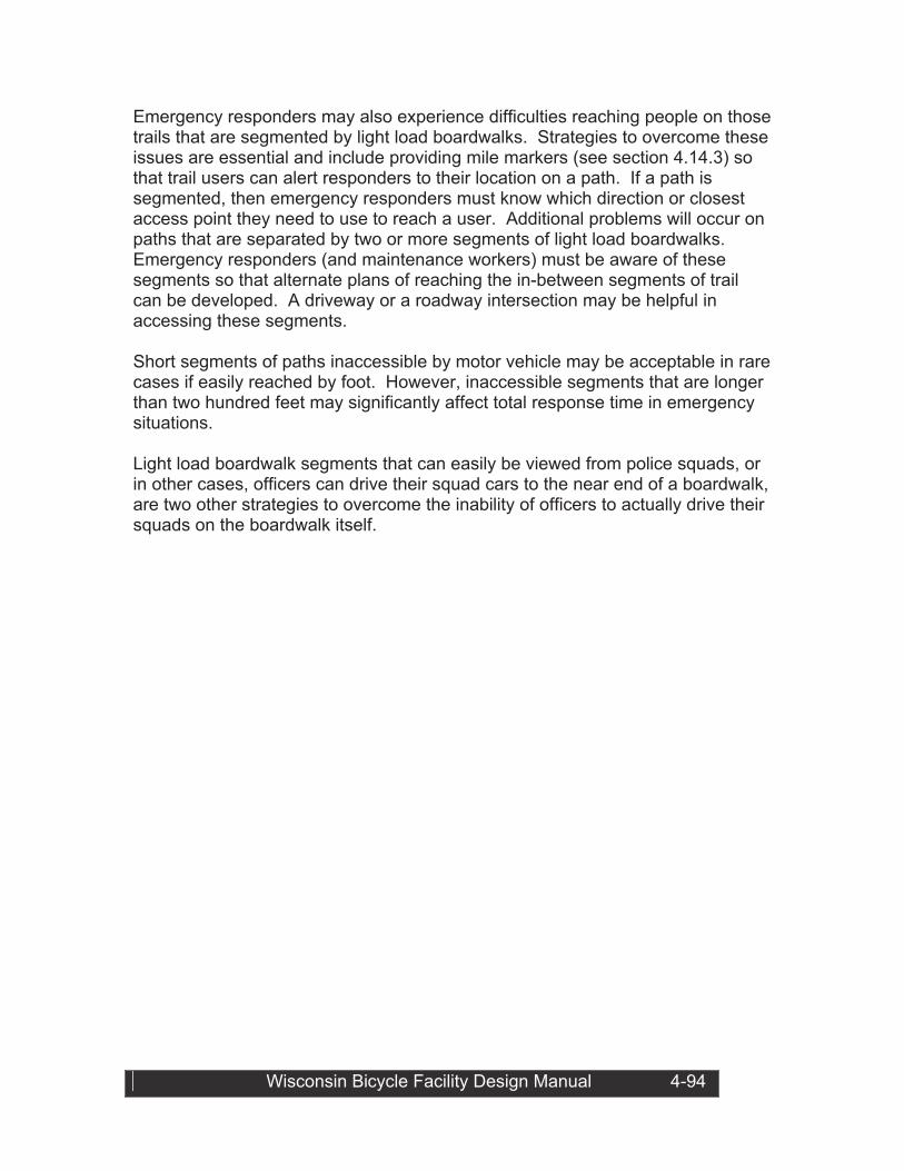
Wisconsin Bicycle Facility Design Manual 4-94
Emergency responders may also experience difficulties reaching people on those trails that are segmented by light load boardwalks. Strategies to overcome these issues are essential and include providing mile markers (see section 4.14.3) so that trail users can alert responders to their location on a path. If a path is segmented, then emergency responders must know which direction or closest access point they need to use to reach a user. Additional problems will occur on paths that are separated by two or more segments of light load boardwalks.Emergency responders (and maintenance workers) must be aware of these segments so that alternate plans of reaching the in-between segments of trail can be developed. A driveway or a roadway intersection may be helpful in accessing these segments.
Short segments of paths inaccessible by motor vehicle may be acceptable in rare cases if easily reached by foot. However, inaccessible segments that are longer than two hundred feet may significantly affect total response time in emergency situations.
Light load boardwalk segments that can easily be viewed from police squads, or in other cases, officers can drive their squad cars to the near end of a boardwalk, are two other strategies to overcome the inability of officers to actually drive their squads on the boardwalk itself.
Appendix AMaintenance & Operations
A.1 General
The development of bicycle facilities has become more popular during the
past decade among communities nationwide. Path systems have sprung
up in the smallest towns and the biggest cities. On-road bicycle lanes
have become a standard feature in some places. And such basic bicy-
cling improvements as bicycle-sensitive traffic signals, bicycle-safe
drainage grates, wide outside travel lanes, or well-marked shoulder
areas, have become almost common.
As the popularity of such facilities has grown, the need for proper mainte-
nance and operations has become obvious. An agency that builds a path,
for instance, must know in advance who will take care of it and where the
money will come from. To this end, it is vital to consider the costs of such
on-going duties in proposals for new and enhanced facilities.
Historically, many paths and lanes have been built or marked only to fall
into disrepair and, eventually, abandonment. These early lessons were
expensive and unfortunate. These days, however, the necessary costs
are being built into project and program budgets. Agencies have long
since learned that there is no such thing as a self-maintaining bicycle
facility.
Still, proper design and construction practices can reduce maintenance
needs substantially. For instance, proper soil treatment beneath a new
path can reduce the intrusion of vegetation and, as a result, may prolong
pavement life. Similarly, paving 15 feet or so into unpaved driveways can
keep most of the debris off a street’s bicycle lanes. And using hydraulical-
ly-efficient bicycle-safe drainage grates can protect bicyclists while
enhancing the removal of storm water runoff.
In addition, some facility maintenance tasks can be handled by small
changes in existing practices. For example, street sweeping patterns may
be adjusted slightly to take care of bicycle lanes. And some traffic signal
crews carry a bicycle wheel in the truck to test new and modified signal
systems for bicycle-sensitivity. Such changes do not require large invest-
ments – just thoughtful adjustments to existing practices.
Another important feature of a bicycle-friendly maintenance program
should be the involvement of users in a positive way. Bicyclists should be
encouraged to report maintenance problems on paths and roadways. A
A-1 Wisconsin Bicycle Facility Design Manual
central contact person with authority to authorize maintenance work
should be designated to receive such reports. Developing a feedback
mechanism (e.g., a “spot improvement” postcard program) can help iden-
tify problems and improve relations with the bicycling public. Some
agency staff have noted that their spot improvement programs were the
most popular things they did.
A.2 Planning and Budgeting
As an agency gains experience with bicycle facility maintenance and
operations, they will learn to estimate future costs for their expanding sys-
tem. Per mile costs for path sweeping or vegetation removal can be deter-
mined if accurate records are kept. Trash removal and emptying of con-
tainers can be predicted based on experience with nearby parks or other
similar facilities. While seasons may change the level of attention
required, there will be an increasing level of predictability as time goes by.
In addition, costs of such things as bicycle lane striping, marking, and
signing can be estimated based on existing costs for similar items. Loop
detectors buried in bicycle lanes to actuate traffic signals are similar to
those buried in regular travel lanes and the costs are similar. Bicycle-safe
drainage grates are sold by the same manufacturers as other styles and
their costs are readily available.
One aspect that must be carefully considered involves maintenance prac-
tices that cannot be handled by existing methods. For instance, a city’s
snow plows may be too large to use on a shared-use path. And some
standard maintenance vehicles may not be able to reach certain areas of
a network. For these reasons, it may be necessary to purchase special
equipment or modify existing vehicles to handle the need. These costs
should be planned for and maintenance and operations crews should be
involved early in the process to anticipate problems before they arise.
The growth of bicycle facility mileage should be carefully watched to
assure that funding for maintenance and operation keep up. While the
special maintenance needs of on-road facilities are a relatively small part
of the overall road maintenance budget, this is not the case with bicycle
paths.
A.3 On-road facilities
On roadways with bicycle lanes, shoulders, or wide outside lanes, debris
may accumulate near the right edge, where most bicyclists ride. There-
fore, regular sweeping is necessary and the paths that operators take
may need to be adjusted to take care of those areas. The sweeping
schedule can vary, depending on local conditions, and should be based
on observation of needs.
Wisconsin Bicycle Facility Design Manual A-2
Pavement quality is also important for bicyclists. Potholes should be
patched to a high standard, as should utility excavation work. In addition,
pavement edges should be uniform and joint lines should be checked for
hazards. Bicycle-oriented signs, striping, and marking should be routinely
inspected and kept in good condition..
Routine roadway maintenance can help improve bicycle travel throughout
a community. Several bicycle facilities described in this guide can be
implemented during routine maintenance activities. When lane markings
are restriped, consideration should be given to adjusting lane widths to
provide bicycle lanes or wide curb lanes. Addition of edge lines can help
delineate a shouldert. When shoulders are resurfaced, a smooth surface
suitable for bicycle riding should be considered.
During the winter, bicycle lanes, shoulders, and the outer edges of curb
lanes should be cleared of snow, like other parts of the road. Snow
should not be left in these areas and should be removed as quickly as
possible.
A.4 Shared-use paths
Shared-use paths may not be visible from nearby roadways and agency
personnel may not know if a problem has arisen. As a result, it is impor-
tant to routinely inspect paths for maintenance problems like overhanging
vegetation, debris on the surface, sight obstructions near curves, etc. Use
patterns should also be observed for indications that problems may be
arising. Bicyclists may cut particular curves or may avoid certain areas.
Such behavior may be the result of a maintenance problem or a design
flaw that could be rectified.
Pavement markings tend to last longer on paths than on roadways,
depending on plowing activity in the winter and other factors. As a result,
stripes may not need to be re-done each year. Signage, however, may be
popular targets for vandalism or theft. Particularly important hazard mark-
ers or regulatory signs should be inspected regularly to ensure they are
still in place.
Lighting, particularly at key intersections or hazardous locations, should
be checked regularly. Lights should be maintained to ensure reliable
operation and should be kept clean and replaced as required to ensure
proper luminescence.
Sight distances at key junctures – intersections with roadways, on the
insides of curves – should not be impaired by encroaching trees, shrubs
and tall grass. Maintaining adequate clear zones on each side of a path
can preserve the facility’s effective width and reduce the potential for
A-3 Wisconsin Bicycle Facility Design Manual
head-on collisions. Tree branches should be trimmed to allow room for sea-sonal growth without encroaching onto the trail. Seeded and sodded areasnear paths should be mowed regularly. Patching and grading of paths should be much less demanding than similarroadway operations. Hand operated equipment may be adequate but it isimportant that finished patches be flush with the surface and use materialsthat will not grip in-line or roller skates, especially for longitudinal fractures.The patchʼs surface should have similar skid resistance characteristics tothe adjoining pathʼs surface.The presence of ruts in the pavement may indicate an improperly designedor built path, or that heavy vehicles are using it. Ruts should be removed togive a satisfactory result and avoid recurrence. Re-paving may be neces-sary to solve major problems. Pavement edges should be maintained topreserve the full paved width; shoulders should not be allowed to washaway, exposing the edges to potential damage or possibly causing users tocrash.Paths built across irregular or hilly land may encounter drainage problems.Heavy storms may wash out portions of path or leave a thick layer of debrison the surface. Sunken areas may indicate problems beneath the pave-ment and should be repaired with care. Providing culverts or small bridgesmay help avoid problems in the future. Drainage ways should be inspectedfor blockages or other problems.Drainage grates are not generally found on path surfaces and should gen-erally be offset from the surface. However, grates should be bicycle-safeeven if they are several feet away from the pavement edge. Bicyclists mayleave the pavement for a variety of reasons and should not have to worryabout a dangerous grate. Generally, shared-use paths do not collect debris to the extent that road-ways do. However, certain locations (e.g., near unpaved roadway cross-ings) may be problem sites and may need occasional attention. In addition,debris at certain critical locations should be monitored. For example, gravelshould not be allowed to accumulate on curves or at intersections. At thoselocations, preventative measures should be taken to keep debris off thepath all together.Winter use varies according to local conditions. In some communities (e.g.,Eau Claire, Madison), paths are plowed regularly and are used frequentlyby bicyclists and pedestrians. Heavily-used paths that serve key destina-tions should be considered first for plowing. Even paths that serve onlyoccasional use should be considered for snow removal if the path is theonly means of making a key connection (e.g., crossing a bridge).
Wisconsin Bicycle Facility Design Manual A-4
Lower priority may be given to isolated paths that serve recreational
users who must travel long distances to use them. In these cases, man-
agers may allow want to allow use by cross country skiers or snowmobile
operators as long as all applicable laws are followed.
To ensure that winter use is properly accommodated, agencies must
clearly understand who will maintain what path. For paths along state
highways, a municipality will have the responsibility for maintenance. Win-
ter use and snow removal frequency will be determined by the municipali-
ty after considering the following factors:
• Expected use by bicyclists and pedestrians;• Parallel options for bicyclists and pedestrians if the path is not
passable; and• State statute 81.15 regarding the liability for accomulation of
snow.
A maintenance plan is crucial to success. And pavement structure must
be designed for snow plow vehicle loading.
Trash receptacles should be located where they will be needed and
where they can be easily emptied. Typical locations for trash barrels
include rest areas and parks, scenic overlooks, and trail heads. Paths
should be kept free of litter and debris.
Generally, path-sides should be given a thorough “Spring cleanup” and
should be checked as needed. Fallen branches or other debris should be
removed as soon as possible after the problem has been reported. User
groups may wish to help out on a regular basis and their efforts should
be encouraged.
Fencing: Fencing along paths should be maintained in the same manner
as highway fencing.
Structures like bridges and underpasses should be inspected regularly
for vandalism, graffiti, structural decay, and missing elements (e.g., lights,
railings, signs). Those in isolated locations may be the targets of more
abuse than facilities in more popular spots. For these reasons, solving
such problems in advance is the best approach. Surfaces should repell
paint, lighting should be hard to damage, and other parts and pieces
should not be easy to remove.
If a path has steps or ramps, these should be maintained at a level that
will safely accommodate users. Wheelchair ramps should be kept in good
condition and graded areas should receive adequate attention.
A-5 Wisconsin Bicycle Facility Design Manual
Some shared-use paths may need occasional (or frequent) enforcement
attention. For example, unauthorized vehicles may be using the path to
get to a recreational location. Or certain areas may be isolated and
potential sites for crimes of violence. The experience with paths is gener-
ally positive, with few crimes beyond what is normally found in the area.
However, it may be good for the local police bicycle patrol to use the
paths regularly to establish their presence.
Wisconsin Bicycle Facility Design Manual A-6
APPENDIX BTraffic conditions & bridge accommodationsBicyclistsʼ needs should be considered on a routine basis for all roadwaysand structures (except those on highways where bicyclists are prohibit-ed). However, prioritizing candidate structures as part of developing aschedule for improvements should be based on traffic conditions; landuse and the transportation system; and geometrics.B.1 Traffic conditionsBicycle traffic volume (potential or actual): A structure on a popular bicy-cling route is a better candidate than one on a road with little or no poten-tial for bicycle use. At the same time, current bicycle volumes may bemisleading indicators of desired use. Bicyclists may avoid using a narrowhigh-speed, high-volume structure out of fear.Bicycle crash experience: Relatively few of those serious bicycle crashesthat result in an emergency room visit are reported to the police. As aresult, a structure with a history of reported bicycle crashes is likely to bethe site of many unreported crashes as well and should receive closescrutiny.Motor vehicle traffic volume: A high-volume structure is more likely toneed bicycle accommodations than a low-volume one, due to theincreased likelihood of passsing conflicts, not to mention the stress ofbicycling on a busy structure.Percent of truck and/or RV traffic: A structure with a high percentage oftruck and/or RV traffic is more likely to need bicycle accommodationsthan one with little or no such traffic. Wind-blast effects of large vehiclescan cause bicyclists to lose control.Traffic speed: High traffic speeds (i.e., over 45mph) are associated with asignificant percentage of bicycling fatalities and structures on such routesneed close attention.B.2 Land use and the transportation systemProximity to bicycle traffic generators: A structure that serves many near-by residents and connects to popular recreation or commercial areas islikely to attract more bicycle use than one far from any community.Alternate routes: If there are no suitable alternate routes, the importanceof a particular structure will be greater than if there are numerousoptions.
B-1 Wisconsin Bicycle Facility Design Handbook
Connecting roadways: A structure that connects only segments of free-
way or expressway is less likely to be in demand than one that connects
surface streets, like collectors or arterials.
Bicycle accommodations: A structure that connects existing or planned
bicycle facilities (e.g., bicycle lanes or routes) is a good candidate for
bicycle-related improvements.
B.3 Geometrics:
Length: The longer a particular structure is, the less use it will get from
casual short-distance bicyclists and the more use it will get from tourists
and other long-distance cyclists.
Elevation: Bridges that arch high for the passage of ships or tunnels that
drop steeply under a river are less attractive for most bicyclists than are
flatter structures. However, on steep structures, the presence of slow-
moving bicyclists on the ascent and fast moving bicyclists on the descent
must be considered.
Width: Because passing opportunities are more limited on two-lane struc-
tures than on multi-lane structures, they are more likely locations for bicy-
cle/motor vehicle conflicts.
Wisconsin Bicycle Facility Design Handbook B-2
Appendix CWisconsin Statutes on Bicycle Equipment and UseThe statutes shown In this material have been generated from the original data base of the 1989-90 Wisconsin Statutes,but may not be an exact duplication. Please refer to the 1989-90 Wisconsin Statutes for the official text.85.07 Highway safety coordination.(4) BICYCLE RULES. The department shall publish literature setting forth the state rules governing bicycles and their opera-tion and shall distribute and make such literature available without charge to local enforcement agencies, safety organiza-tions, and schools and to any other person upon request.340.01 Words and phrases defined. In s.23.33 and chs.340 to 349 and 351, the following words and phrases havethe designated meanings unless a different meaning is expressly provided or the context clearly indicates a differentmeaning:(5) “Bicycle” means every device propelled by the feet acting upon pedals and having wheels any 2 of which are not lessthan 14 inches in diameter. (5e) “Bicycle lane” means that portion of a roadway set aside by the governing body of any city, town, village or county forthe exclusive use of bicycles or other modes of travel where permitted under s.349.23 (2) (a) and so designated by appro-priate signs and markings. (5m) “Bike route” means any bicycle lane, bicycle way or highway which has been duly designated by the governing bodyof any city, town, village or county and which is identified by appropriate signs and markings. (5s) “Bicycle way” means any path or sidewalk or portion thereof designated for the use of bicycles by the governing bodyof any city, town, village or county. (74) “Vehicle” means every device in, upon or by which any person or property is or may be transported or drawn upon ahighway, except railroad trains. A snowmobile shall not be considered a vehicle except for purposes made specificallyapplicable by statute.346.02 Applicability of chapter.(4) APPLICABILITY TO PERSONS RIDING BICYCLES AND MOTOR BICYCLES.(a) Subject to the special provisions applicable to bicycles, every person riding a bicycle upon a roadway is granted allthe rights and is subject to all the duties which this chapter grants or applies to the operator of a vehicle, except thoseprovisions which by their express terms apply only to motor vehicles or which by their very nature would have no appli-cation to bicycles. For purposes of this chapter, provisions which apply to bicycles also apply to motor bicycles, exceptas otherwise expressly provided. (b) Provisions which apply to the operation of bicycles in crosswalks under ss. 346.23, 346.24, 346.37 (1) (a) 2, (c) 2and (d) 2 and 346.38 do not apply to motor bicycles.346.075 Overtaking and passing bicycles and motor buses.(1) The operator of a motor vehicle overtaking a bicycle proceeding in the same direction shall exercise due care, leaving asafe distance, but in no case less than 3 feet clearance when passing the bicycle and shall maintain clearance until safelypast the overtaken bicycle.346.16 Use of controlled-access highways, expressways and freeways.(1) No person shall drive a vehicle onto or from a controlled- access highway, expressway or freeway except through anopening provided for that purpose. (2) (a) Except as provided in par. (b), no pedestrian or person riding a bicycle or other non-motorized vehicle and no per-son operating a moped or motor bicycle may go upon any expressway or freeway when official signs have been erectedprohibiting such person from using the expressway or freeway.(b) A pedestrian or other person under par. (a) may go upon a portion of a hiking trail, cross-country ski trail, bridletrail or bicycle trail incorporated into the highway right-of-way and crossing the highway if the portion of the trail isconstructed under s. 84.06 (I 1).C-1 Wisconsin Bicycle Facility Design Manual
346.17 Penalty for violating sections 346.04 to 346.16.(2) Any person violating ss. 346.05, 346.07 (2) or (3), 346.08 to 346.11, 346.13 (2) or 346.14 to 346.16 may berequired to forfeit not less than $30 nor more than $300.(4) Any person violating s. 346.075 may be required to forfeit not less than $25 nor more than $200 for the first offenseand not less than $50 nor more than $500 for the 2nd or subsequent violation within 4 years.346.23 Crossing controlled Intersection or crosswalk. (1) At an intersection or crosswalk where traffic is controlled by traffic control signals or by a traffic officer, the operator ofa vehicle shall yield the right-of-way to a pedestrian, or to a person who is riding a bicycle in a manner which is consistentwith the safe use of the crosswalk by pedestrians, who has started to cross the highway on a green or “Walk” signal andin all other cases pedestrians and bicyclists shall yield the right-of-way to vehicles lawfully proceeding directly ahead on agreen signal. No operator of a vehicle proceeding ahead on a green signal may begin a turn at a controlled intersection orcrosswalk when a pedestrian or bicyclist crossing in the crosswalk on a green or “Walk” signal would be endangered orinterfered with in any way. The rules stated in this subsection are modified at intersections or crosswalks on divided high-ways or highways provided with safety zones in the manner and to the extent stated in sub. (2).(2) At intersections or crosswalks on divided highways or highways provided with safety zones where traffic is controlled bytraffic control signals or by a traffic officer, the operator of a vehicle shall yield the right-of-way to a pedestrian or bicyclistwho has started to cross the roadway either from the near curb or shoulder or from the center dividing strip or a safetyzone with the green or “Walk” signal in the pedestrian’s or bicyclist’s favor.346.24 Crossing at uncontrolled Intersection or crosswalk. (1) At an intersection or crosswalk where traffic is not controlled by traffic control signals or by a traffic officer, the opera-tor of a vehicle shall yield the right-of-way to a pedestrian, or to a person riding a bicycle in a manner which is consistentwith the safe use of the crosswalk by pedestrians, who is crossing the highway within a marked or unmarked crosswalk.(2) No pedestrian or bicyclist shall suddenly leave a curb or other place of safety and walk, run or ride into the path of avehicle which is so close that it is difficult for the operator of the vehicle to yield.(3) Whenever any vehicle is stopped at an intersection or crosswalk to permit a pedestrian or bicyclist to cross the road-way, the operator of any other vehicle approaching from the rear shall not overtake and pass the stopped vehicle.346.25 Crossing at place other than crosswalk. Every pedestrian or bicyclist crossing a roadway at any point otherthan within a marked or unmarked crosswalk shall yield the right-of-way to all vehicles upon the roadway.346.30 Penalty for violating sections 346.23 to 346.29.(1) 2. Any operator of a bicycle violating s. 346,23, 346.24 or 346.25 may be required to forfeit not more than $20.346.34 Turning movements and required signals on turning and stopping.(1) TURNING.(a) No person may: 1. Turn a vehicle at an intersection unless the vehicle is in proper position upon the roadway as required in s.346.31.2. Turn a vehicle to enter a private road or driveway unless the vehicle is in proper position on the roadway asrequired in s. 346.32. 3. Turn a vehicle from a direct course or move right or left upon a roadway unless and until such movement canbe made with reasonable safety.(b) In the event any other traffic may be affected by such movement, no person may so turn any vehicle without givingan appropriate signal in the manner provided in s. 346.35. When given by the operator of a vehicle other than a bicy-cle, such signal shall be given continuously during not less than the last 100 feet traveled by the vehicle before turn-ing. The operator of a bicycle shall give such signal continuously during not less than the last 50 feet traveled beforeturning.(2) STOPPING. No person may stop or suddenly decrease the speed of a vehicle without first giving an appropriate signalin the manner provided in s. 346.35 to the operator of any vehicle immediately to the rear when there is opportunity togive such signal. This subsection does not apply to the operator of a bicycle approaching an official stop sign or trafficcontrol signal.
Wisconsin Bicycle Facility Design Manual C-2
346.35 Method of giving signals on turning and stopping. Whenever a stop or turn signal is required by s. 346.34,such signal may in any event be given by a signal lamp or lamps of a type meeting the specifications set forth in s.347.15. Except as provided in s. 347.15 (3m), such signals also may be given by the hand and arm in lieu of or in addi-tion to signals by signal lamp. When given by hand and arm, such signals shall be given from the left side of the vehicle inthe following manner and shall indicate as follows:(1) Left turn-Hand and arm extended horizontally.(2) Right turn-Hand and arm extended upward.(3) Stop or decrease speed-Hand and arm extended downward.346.36 Penalty for violating sections 346.31 to 346.35.(2) Any operator of a bicycle violating ss. 346.31 to 346.35 may be required to forfeit not more than $20.346.37 Traffic-control signal legend.(1) Whenever traffic is controlled by traffic control signals exhibiting different colored lights successively, or with arrows,the following colors shall be used and shall indicate and apply to operators of vehicles and pedestrians as follows:(a) Green. 1. Vehicular traffic facing a green signal may proceed straight through or turn right or left unless a sign at suchplace prohibits either such turn, but vehicular traffic shall yield the right of way to other vehicles and to pedestrianslawfully within the intersection or an adjacent crosswalk at the time such signal is exhibited.2. Pedestrians, and persons who are riding bicycles in a manner which is consistent with the safe use of thecrosswalk by pedestrians, facing the signal may proceed across the roadway within any marked or unmarkedcrosswalk.(b) Yellow. When shown with or following the green, traffic facing a yellow signal shall stop before entering the inter-section unless so close to it that a stop may not be made in safety.(c) Red. 1. Vehicular traffic facing a red signal shall stop before entering the crosswalk on the near side of an intersection,or if none, then before entering the intersection or at such other point as may be indicated by a clearly visible signor marking and shall remain standing until green or other signal permitting movement is shown.2. No pedestrian or bicyclist facing such signal shall enter the roadway unless he or she can do so safely andwithout interfering with any vehicular traffic.3. Vehicular traffic facing a red signal at an intersection may, after stopping as required under subd. 1, cautiouslyenter the intersection to make a right turn into the nearest lawfully available lane for traffic moving to the right or toturn left from a one-way highway into the nearest lawfully available lane of a one-way highway on which vehiculartraffic travels to the left. No turn may be made on a red signal if lanes of moving traffic are crossed or if a sign atthe intersection prohibits a turn. In making a turn on a red signal vehicular traffic shall yield the right-of-way topedestrians and bicyclists lawfully within a crosswalk and to other traffic lawfully using the intersection.(d) Green arrow. 1. Vehicular traffic facing a green arrow signal may enter the intersection only to make the movement indicated bythe arrow but shall yield the right-of-way to pedestrians and bicyclists lawfully within a crosswalk and to other traf-fic lawfully using the intersection. When the green arrow signal indicates a right or left turn traffic shall cautiouslyenter the intersection.2. No pedestrian or bicyclist facing such signal shall enter the roadway unless he or she can do so safely andwithout interfering with any vehicular traffic.(2) In the event an official traffic signal is erected and maintained at a place other than an intersection, the provisions ofthis section are applicable except as to those provisions which by their nature can have no application. Any stop requiredshall be made at a sign or marking on the pavement indicating where the stop shall be made, but in the absence of anysuch sign or marking the stop shall be made at the signal.346.38 Pedestrian control signals. Whenever special pedestrian control signals exhibiting the words “Walk” or “Don’tWalk” are in place, such signals indicate as follows:(1) WALK. A pedestrian, or a person riding a bicycle in a manner which is consistent with the safe use of the crossing bypedestrians, facing a “Walk” signal may proceed across the roadway or other vehicular crossing in the direction of the sig-nal and the operators of all vehicles shall yield the right-of-way to the pedestrian or bicyclist.(2) DON’T WALK. No pedestrian or bicyclist may start to cross the roadway or other vehicular crossing in the direction of a“Don’t Walk” signal, but any pedestrian or bicyclist who has partially completed crossing on the “Walk” signal may pro-ceed to a sidewalk or safety zone while a “Don’t Walk” signal is showing.C-3 Wisconsin Bicycle Facility Design Manual
346.43 Penalty for violating sections 346.37 to 346.42. (1) (b) 2. Any operator of a bicycle violating s. 346.37, 346.38 or 346.39 (duty to obey traffic lights) may be required toforfeit not more than $20.346.47 When vehicles using alley or non-highway access to stop.(1) The operator of a vehicle emerging from an alley or about to cross or enter a highway from any point of access otherthan another highway shall stop such vehicle immediately prior to moving on to the sidewalk or on to the sidewalk areaextending across the path of such vehicle and shall yield the right-of-way to any pedestrian or bicyclist and upon crossingor entering the roadway shall yield the right-of-way to all vehicles approaching on such roadway.346.49 Penalty for violating ss. 346.” to 346.485. (1) (b) Any operator of a bicycle violating s. 346.46 (duty to obey stop signs) may be required to forfeit not more than $20. (2) (b) Any operator of a bicycle violating s. 346.44 (duty to stop at signals indicating approach of train) may be requiredto forfeit not more than $20.346.59 Minimum speed regulation.(2) The operator of a vehicle moving at a speed so slow as to impede the normal and reasonable movement of trafficshall, if practicable, yield the roadway to an overtaking vehicle whenever the operator of the overtaking vehicle gives audi-ble warning with a warning device and shall move at a reasonably increased speed or yield the roadway to overtakingvehicles when directed to do so by a traffic officer.346.60 Penalty for violating sections 346.57 to 346.595(5) (a) Any operator of a bicycle who violates s. 346.57 (speed limits) may be required to forfeit not more than $20. (b) Any operator of a bicycle who violates s. 346.59 may be required to forfeit not more than $10.346.77 Responsibility of parent or guardian for violation of bicycle and play vehicle regulations. No parent orguardian of any child shall authorize or knowingly permit such child to violate any of the provisions of ss. 346.78 to346.804 and 347.489.346.78 Play vehicles not to be used on roadway. No person riding upon any play vehicle may attach the same or him-self or herself to any vehicle upon a roadway or go upon any roadway except while crossing a roadway at a crosswalk.346.79 Special rules applicable to bicycles. Whenever a bicycle is operated upon a highway, bicycle lane or bicycleway the following rules apply: (1) A person propelling a bicycle shall not ride other than upon or astride a permanent and regular seat attached thereto. (2) (a) Except as provided in par. (b) no bicycle may be used to carry or transport more persons at one time than the num-ber for which it is designed. (b) In addition to the operator, a bicycle otherwise designed to carry only the operator may be used to carry or trans-port a child seated in an auxiliary child’s seat or trailer designed for attachment to a bicycle if the seat or trailer issecurely attached to the bicycle according to the directions of the manufacturer of the seat or trailer. (3) No person operating a bicycle shall carry any package, bundle or article which prevents the operator from keeping atleast one hand upon the handle bars. (4) No person riding a bicycle shall attach himself or his bicycle to any vehicle upon a roadway. (5) No person may ride a moped or motor bicycle with the power unit in operation upon a bicycle way.
Wisconsin Bicycle Facility Design Manual C-4
346.80 Riding bicycle on roadway.(1) Unless preparing to make a left turn, every person operating a bicycle upon a roadway carrying 2-way traffic shall rideas near as practicable to the right edge of the unobstructed traveled roadway, including operators who are riding 2 abreastwhere permitted under sub. (2). On one-way roadways, the operator of the bicycle shall ride as near as practicable to theright edge or left edge of the unobstructed traveled roadway, including operators who are riding 2 abreast where permittedunder sub. (2). Every person operating a bicycle upon a roadway shall exercise due care when passing a standing vehicleor one proceeding in the same direction, allowing a minimum of 3 feet between the bicycle and the vehicle. (2) Persons riding bicycles upon a roadway shall ride single file on all roadways which have center lines or lane lines indi-cated by painting or other markings and in all unincorporated areas. On roadways not divided by painted or other markedcenter lines or lane lines, bicycle operators may ride 2 abreast in incorporated areas.(4) No person may operate a bicycle or moped upon a roadway where a sign is erected indicating that bicycle or mopedriding is prohibited. (5) Except as provided in ss. 346.23, 346.24, 346.37 and 346.38, every rider of a bicycle shall, upon entering on a high-way, yield the right-of-way to motor vehicles.346.802 Riding bicycle on bicycle lane. (1) (a) Unless 2-way traffic is authorized under par. (b), every person operating a bicycle upon a bicycle lane shall ride inthe same direction in which vehicular traffic on the lane of the roadway nearest the bicycle lane is traveling. (b) The governing body of any city, town, village or county may authorize 2-way traffic on any portion of a roadwaywhich it has set aside as a bicycle lane. Appropriate traffic signs shall be installed on all bicycle lanes open to 2-waytraffic.(2) (a) Unless otherwise provided under par. (b), a person operating a bicycle may enter or leave a bicycle lane only atintersections or at driveways adjoining the bicycle lane. (b) A person may leave a bicycle lane at any point by dismounting from the bicycle and walking it out of the lane. Aperson may enter a bicycle lane at any point by walking his bicycle into the lane and then mounting it. (3) Every person operating a bicycle upon a bicycle lane shall exercise due care and give an audible signal when passing abicycle rider proceeding in the same direction. (4) Every operator of a bicycle entering a bicycle lane shall yield the right-of-way to all bicycles in the bicycle lane. Uponleaving a bicycle lane, the operator of a bicycle shall yield the right-of-way to all vehicles and pedestrians.346.803 Riding bicycle on bicycle way. (1) Every person operating a bicycle upon a bicycle way shall:(a) Exercise due care and give an audible signal when passing a bicycle rider or a pedestrian proceeding in the samedirection.(b) Obey each traffic signal or sign facing a roadway which runs parallel and adjacent to a bicycle way. (2) Every person operating a bicycle upon a bicycle way open to 2- way traffic shall ride on the right side of the bicycleway.(3) Every operator of a bicycle entering a bicycle way shall yield the right-of-way to all bicycles and pedestrians in the bicy-cle way.346.804 Riding bicycle on sidewalk. When local authorities under s. 346.94 (1) permit bicycles on the sidewalk, everyperson operating a bicycle upon a sidewalk shall yield the right-of-way to any pedestrian and shall exercise due care andgive an audible signal when passing a bicycle rider or pedestrian proceeding in the same direction.346.82 Penalty for violating sections 346.77 to 346.804.(1) Any person violating ss. 346.77, 346.79 (1) to (3) or 346.80 to 346.804 may be required to forfeit not more than $20. (2) Any person violating s. 346.78 or 346.79 (4) may be required to forfeit not less than $10 nor more than $20 for thefirst offense and not less than $25 nor more than $50 for the 2nd or subsequent conviction within a year.346.94 Miscellaneous prohibited acts.(1) DRIVING ON SIDEWALK. The operator of a vehicle shall not drive upon any sidewalk area except at a permanent ortemporarily established driveway unless permitted to do so by the local authorities. C-5 Wisconsin Bicycle Facility Design Manual
(11) TOWING SLEDS, ETC. No person shall operate any vehicle or combination of vehicles upon a highway when suchvehicle or combination of vehicles is towing any toboggan, sled, skis, bicycle, skates or toy vehicle bearing any person. (12) DRIVING ON BICYCLE LANE OR BICYCLE WAY. No operator of a motor vehicle may drive upon a bicycle lane or bicy-cle way except to enter a driveway or to enter or leave a parking space located adjacent to the bicycle lane or bicycle way.Persons operating a motor vehicle upon a bicycle lane or bicycle way shall yield the right-of-way to all bicycles within thebicycle lane or bicycle way.346.95 Penalty for violating sections 346.87 to 346.94.(1) Any person violating s. 346.87, 346.88, 346.89 (2), 346.90 to 346.92 or 346.94 (1), (9), (10), (11), (12) or (I 5) maybe required to forfeit not less than $20 nor more than $40 for the first offense and not less than $50 nor more than $I 00for the 2nd or subsequent conviction within a year.347.489 Lamps and other equipment on bicycles and motor bicycles.(1) No person may operate a bicycle or motor bicycle upon a highway, bicycle lane or bicycle way during hours of dark-ness unless the bicycle or motor bicycle is equipped with or the operator is wearing a lamp emitting a white light visiblefrom a distance of at least 500 feet to the front of the bicycle or motor bicycle. A bicycle or motor bicycle shall also beequipped with a red reflector that has a diameter of at least 2 inches of surface area on the rear so mounted and main-tained as to be visible from all distances from 50 to 500 feet to the rear when directly in front of lawful upper beams ofheadlamps on a motor vehicle. A lamp emitting a red light visible from a distance of 500 feet to the rear may be used inaddition to but not in lieu of the red reflector.(2) No person may operate a bicycle or motor bicycle upon a highway, bicycle lane or bicycle way unless it is equippedwith a brake in good working condition, adequate to control the movement of and to stop the bicycle or motor bicyclewhenever necessary. (3) No bicycle or motor bicycle may be equipped with nor may any person riding upon a bicycle or motor bicycle use anysiren or compression whistle.347.50 Penalties.(5) Any person violating s. 347.489 may be required to forfeit not more than $20.349.105 Authority to prohibit certain traffic on expressways and freeways. The authority in charge of maintenanceof an expressway or freeway may, by order, ordinance or resolution, prohibit the use of such expressway or freeway bypedestrians, persons riding bicycles or other non-motorized traffic or by persons operating mopeds or motor bicycles. Thestate or local authority adopting any such prohibitory regulation shall erect and maintain official signs giving notice thereofon the expressway or freeway to which such prohibition applies.349.18 Additional traffic-control authority of counties and municipalities.(2) (a) Except as provided in par. (b), any city, town or village may by ordinance regulate the operation of bicycles andmotor bicycles and require registration of any bicycle or motor bicycle owned by a resident of the city, town or village,including the payment of a registration fee.(b) A city, town or village may not prohibit the use of a bicycle equipped as provided in s. 346.79 (2) (b) to carry ortransport a child in addition to the operator of the bicycle. (3) Any county, by ordinance, may require the registration of any bicycle or motor bicycle owned by a resident of the coun-ty if the bicycle or motor bicycle is not subject to registration under sub. (2). Such ordinance does not apply to any bicycleor motor bicycle subject to registration under sub. (2), even if the effective date of the ordinance under sub. (2) is laterthan the effective date of the county ordinance. A county may charge a fee for the registration.349.23 Authority to designate bicycle lanes and bicycle ways.(1) The governing body of any city, town, village or county may by ordinance:(a) Designate any roadway or portion thereof under its jurisdiction as a bicycle lane.(b) Designate any sidewalk or portion thereof in its juris- diction as a bicycle way.(2) A governing body designating a sidewalk or portion thereof as a bicycle way or a highway or portion thereof as a bicy-cle lane under this section may:(a) Designate the type and character of vehicles or other modes of travel which may be operated on a bicycle lane orbicycle way, provided that the operation of such vehicle or other mode of travel is not inconsistent with the safe use
Wisconsin Bicycle Facility Design Manual C-6
and enjoyment, of the bicycle lane or bicycle way by bicycle traffic.(b) Establish priority of right-of-way on the bicycle lane or bicycle way and otherwise regulate the use of the bicyclelane or bicycle way as it deems necessary. The designating governing body may, after public hearing, prohibit throughtraffic on any highway or portion thereof designated as a bicycle lane, except that through traffic may not be prohibitedon any state highway. The designating governing body shall erect and maintain official signs giving notice of the regu-lations and priorities established under this paragraph, and shall mark all bicycle lanes and bicycle ways with appropri-ate signs.(c) Paint lines or construct curbs or establish other physical separations to exclude the use of the bicycle lane or bicy-cle way by vehicles other than those specifically permitted to operate thereon. (3) The governing body of any city, town, village or county may by ordinance prohibit the use of bicycles and motor bicy-cles on a roadway over which they have jurisdiction, after holding a public hearing on the proposal.
C-7 Wisconsin Bicycle Facility Design Manual
Appendix DBibliography
AASHTO Maintenance Manual, American Association of State Highway &
Transportation Officials, 1987
Americans with Disabilities Act, U.S. Congress, 1990
Americans with Disabilities Act Accessibility Guidelines, U.S. Access
Board, 2002
Arizona Bicycle Facilities Planning & Design Guidelines, Arizona DOT, 1988
Bicycle Facilities Planning and Design Handbook, Florida Department of
Transportation, 2000
Bicycle Transportation Plan for Madison Urban Area and Dane County,
Dane County Regional Planning Commission and Madison Department of
Transportation, 2000
California Highway Design Manual, Ch. 1000, California DOT, 1995
Facilities Development Manual, Wisconsin DOT, 2001
FHWA Guidance: Bicycle & Pedestrian Provisions of Federal Transporta-
tion Legislation, Federal Highway Administration, 1999
Guide for Development of Bicycle Facilities, American Association of State
Highway and Transportation Officials, 1999
Guidelines for Developing Rural Bike Routes, Wisconsin Departments of
Transportation and Natural Resources, 1975
Highway Design Manual, Sec. 1020, Washington State Department of Trans-
portation, 1989
Manual on Uniform Traffic Control Devices, FHWA, 2000
Minnesota Bicycle Transportation Planning and Design Guidelines, Min-
nesota Department of Transportation, 1996
Montana Public Works Standard Specifications, Montana Contractor's Asso-
ciation, 1988
Mountain Bike Trails, Techniques for Design, Construction and Maintenance,
Bikecentennial, 1990
North Carolina Bicycle Facilities Planning & Design Guidelines, North Car-
olina DOT, 1996
Oregon Bicycle and Pedestrian Plan, Oregon Bikeway/Pedestrian Office, 1996
Planning for Rural Bicycle Routes, Van Valkenburg, Wisconsin DOT, 1993
Policy on Geometric Design of Highways and Streets, AASHTO, 2001
Re-Evaluating Signal Detector Loops, Alan Wachtel, NCBW Forum 2001
Sign up for the Bike: Design Manual for a Cycle Friendly Infrastructure,
Centre for Research and Contract Standardization in Civil and Traffic Engi-
neering, Netherlands, 1994
Title 23 U.S.C. §217: Bicycle Transportation and Pedestrian Walkways, Con-
gress of the United States
Traffic Calming - State of the Practice, Institute of Transportation Engineers,
1999
Trail Intersection Design Handbook; Florida DOT, 1996
Wisconsin Bicycle Transportation Plan 2020, Wisconsin DOT, 1998
Wisconsin Bicycle Facility Design Handbook D-1
E-1 Wisconsin Bicycle Facility Design Handbook
IndexAggregate structural section, path ................................4-31Arterial streets .................................................................2-4Asphalt structural section, path .....................................4-30Basic Roadway Improvements........................................2-1Bicycle and bicyclist characteristics ................................1-2Bicycle detection, signals ..............................................2-27Bicycle lanes ...................................................................3-1Bicycle lane designation................................................3-14Bicycle lane intersection design ....................................3-18Bicycle lane location........................................................3-3Bicycle lane surface quality .............................................3-8Bicycle lane width............................................................3-9Bicycle Route Designation ............................................2-45Bridges, roadway...........................................................2-32Bridges and overpasses, path.......................................4-72Collector streets ..............................................................2-2Concrete structural section, path ..................................4-31Corner sight lines ..........................................................2-12Cross-country skiers, path.............................................4-92Crossing design, path....................................................4-55Crossing locations, path ................................................4-47Crossings - important features, path .............................4-67Design options.................................................................1-5Design Speed, path.......................................................4-11Designing paths vs. roads...............................................4-2Drainage, path...............................................................4-34Drainage grates and utility covers, roadway ...................2-9Foundation preparation, path ........................................4-29Grade separations, path................................................4-69Grades, path..................................................................4-17Grades, roadway ...........................................................2-20Grate or utility cover elevation.......................................2-11 Grate or utility cover location.........................................2-10Grate temporary measures ...........................................2-11Grate type........................................................................2-9Guardrails and slopes, shoulders..................................2-20Horizontal alignment & superelevation, path.................4-13Horses, path ..................................................................4-91Informational signs, markings, path ..............................4-42Interchanges, bike lane .................................................3-24Interchanges, roadway ..................................................2-36Intersections with right-turn lanes, bike lane.................3-21Joints between travel lanes and shoulders ...................2-21Left-turn, bicycle lane ....................................................3-23Lighting, path.................................................................4-35Low-volume rural roads, shoulders ...............................2-17Maintenance & Operations .............................................A-1Motorbikes and motorcycles, path ................................4-86Motor vehicles, path ......................................................4-87One-way vs. two-way bicycle lanes ................................3-2Parallel crossings, path .................................................4-63Path intersection: yes or no?.........................................4-48Path-Roadway Crossings..............................................4-47Paths in roadway medians ..............................................4-7Paths next to roadways, problems ..................................4-3Paved shoulders, roadway ............................................2-17Pavement quality, roadway .............................................2-7Pavement loads, path....................................................4-27Pavement structure, path ..............................................4-25Pedestrians and Bicyclists, path ...................................4-83 Programmed visibility heads, signals ............................2-30
Railroad crossing angles and gaps ...............................2-23Railroad crossing smoothness ......................................2-26Railroad, crossings, path...............................................2-26Railroad crossings, roadway .........................................2-23Regulatory controls, path ..............................................4-38Residential streets...........................................................2-1Retrofitting wide outside lanes, roadway.......................2-15Roadway types................................................................2-1Rumble strips, roadway.................................................2-22Rural highways................................................................2-5Rural crossings, path ...................................................4-50Rural vs. urban/suburban locations, path......................4-50Shared Use, path ..........................................................4-83Shared-use paths ............................................................4-1Shared-use paths and roadways ....................................4-3Shared-use paths in roadway medians...........................4-7Shared-use path users, purposes, and locations............4-1Shoulder pavement design and loading, roadway ........2-21Shoulder width, roadway ...............................................2-18Shoulders and clearances, path......................................4-9Sidewalk bikeways ..........................................................4-6Sight distance, path.......................................................4-19Signal loop markings .....................................................2-29Signal timing..................................................................2-30Signalized crossings, path.............................................4-61Signalized parallel crossings, path................................4-65Signed parallel crossings, path .....................................4-66Signed crossings with traffic calming, path ...................4-59Signing and marking, path ............................................4-38Sign placement, path.....................................................4-45Sign sizes, path .............................................................4-46Signs - using restraint, path ..........................................4-46Simple signed crossing, path ........................................4-56Snowmobiles, path ........................................................4-92 Structures, path .............................................................4-71Structures, combined road/path ....................................4-79Structures, combined - separation ...............................4-81Structures, roadway ......................................................2-31Surface smoothness and maintenance, path................4-33Traffic calming, roadway ...............................................2-39Traffic calming measures for slowing traffic, roadway ..2-42Traffic diversion approaches, roadway .........................2-40Traffic conditions & bridges, roadway.............................B-1Traffic signals ................................................................2-27Transitions between grades and level ground, path .....4-18Underpasses and tunnels, path ....................................4-75Unpaved driveways, roadway .......................................2-21Urban/suburban crossings, path ..................................4-53Vegetation Control, path................................................4-28Warning devices, path...................................................4-41Wide outside lanes ........................................................2-13Wisconsin Statutes .........................................................C-1Work zone controls, path ..............................................4-44Width, path ......................................................................4-7

WISCONSIN BICYCLE FACILITY DESIGN HANDBOOKWisconsin Department of Transportation
2004