Embed Size (px)
Citation preview

Preliminary Engineering Report Woodlea Road
Prepared for:
Lake County Public Works 437 Ardice Avenue
Eustis, Florida 32726
Prepared by:
615 Crescent Executive Court
Suite 106 Lake Mary, FL 32746
November 2006

i
TABLE OF CONTENTS
1.0 EXECUTIVE SUMMARY_______________________________________________1-1
1.1 COMMITMENTS _________________________________________________________1-1
1.2 RECOMMENDATIONS ___________________________________________________1-1
1.3 ANTICIPATED COSTS OF IMPROVEMENTS _______________________________1-2
2.0 INTRODUCTION _____________________________________________________2-1
2.1 PROJECT DESCRIPTION _________________________________________________2-1
2.2 PURPOSE AND OBJECTIVES______________________________________________2-1
3.0 NEED FOR IMPROVEMENT ___________________________________________3-1
3.1 CONSISTENCY WITH TRANSPORTATION PLAN ___________________________3-1
3.2 SAFETY _________________________________________________________________3-1
3.3 SOCIO–ECONOMIC IMPACT _____________________________________________3-1
4.0 EXISTING CONDITIONS ______________________________________________4-1
4.1 EXISTING ROADWAY CHARACTERISTICS ________________________________4-1 4.1.1 Functional Classification ________________________________________________________ 4-1 4.1.2 Posted Speed Limit and Advisory Speeds___________________________________________ 4-1 4.1.3 Typical Sections _______________________________________________________________ 4-3 4.1.4 Pedestrian Facilities ____________________________________________________________ 4-5 4.1.5 Bicycle Facilities _______________________________________________________________ 4-8 4.1.6 Right-of-Way__________________________________________________________________ 4-8 4.1.7 Horizontal Alignment___________________________________________________________ 4-8 4.1.8 Vertical Alignment ____________________________________________________________ 4-12 4.1.9 Drainage ____________________________________________________________________ 4-12 4.1.9.1 General Watershed Description _______________________________________________ 4-12 4.1.9.2 Existing Drainage Basins_____________________________________________________ 4-12 4.1.10 Geotechnical Investigation ___________________________________________________ 4-15 4.1.10.1 Pavement Core Results ______________________________________________________ 4-15 4.1.10.2 Description of Subsurface Conditions __________________________________________ 4-16 4.1.10.3 Soil Strata _________________________________________________________________ 4-17 4.1.10.4 Groundwater Levels ________________________________________________________ 4-17

ii
4.1.11 Accident Data ______________________________________________________________ 4-18 4.1.12 Intersections and Signalization ________________________________________________ 4-18 4.1.13 Lighting___________________________________________________________________ 4-19 4.1.14 Utilities ___________________________________________________________________ 4-20 4.1.15 Pavement Conditions ________________________________________________________ 4-21
4.2 ENVIRONMENTAL CHARACTERISTICS__________________________________4-22 4.2.1 Environmental________________________________________________________________ 4-22 4.2.1.1 Existing Land Use __________________________________________________________ 4-22 4.2.1.2 Future Land Use ___________________________________________________________ 4-22 4.2.1.3 Cultural Features and Community Services _____________________________________ 4-22 4.2.2 Economic ____________________________________________________________________ 4-23 4.2.3 Historical ____________________________________________________________________ 4-23
4.3 HYDROLOGIC AND NATURAL FEATURES _______________________________4-23 4.3.1 Hydrogeography ______________________________________________________________ 4-23 4.3.2 Soils ________________________________________________________________________ 4-24 4.3.3 Land Use and Cover ___________________________________________________________ 4-26 4.3.4 Wetlands ____________________________________________________________________ 4-29 4.3.5 Regulated Floodplains _________________________________________________________ 4-31
4.4 THREATENED & ENDANGERED SPECIES ________________________________4-31
4.5 CONTAMINATION SITES ________________________________________________4-32
5.0 SIGN CONTROLS AND STANDARDS____________________________________5-1
5.1 GEOMETRIC DESIGN CRITERIA__________________________________________5-1
5.2 DRAINAGE DESIGN CRITERIA ___________________________________________5-2
5.2.1 Stormwater Management __________________________________________________________ 5-2
5.2.1.1 General Design Criteria _________________________________________________________ 5-2
5.2.1.2 Wet Retention/Detention Facility Design Criteria ____________________________________ 5-4
5.2.2 Hydraulics ______________________________________________________________________ 5-5
6.0 TRAFFIC ____________________________________________________________6-1
6.1 2025 TRANSPORTATION PLAN____________________________________________6-1
6.2 TRAFFIC ANALYSIS _____________________________________________________6-1

iii
6.3 INTERSECTIONS ________________________________________________________6-1
7.0 PRELIMINARY DESIGN ANALYSIS_____________________________________7-1
7.1 PROJECT SCOPE ________________________________________________________7-1
7.2 TYPICAL SECTIONS _____________________________________________________7-1
7.3 ALIGNMENT IMPROVEMENTS ___________________________________________7-5
7.4 RELOCATIONS __________________________________________________________7-6
7.5 RIGHT-OF-WAY COSTS __________________________________________________7-6
7.6 CONSTRUCTION COSTS _________________________________________________7-6
7.7 PEDESTRIAN / BICYCLE FACILITIES _____________________________________7-6
7.8 SAFETY _________________________________________________________________7-7
7.9 UTILTIY IMPACTS_______________________________________________________7-7
7.10 MAINTENANCE OF TRAFFIC / CONSTRUCTION IMPACTS _________________7-7
7.11 DRAINAGE ______________________________________________________________7-7 7.11.1 Stormwater Management Alternatives __________________________________________ 7-7 7.11.2 Pond Siting Analysis _________________________________________________________ 7-9
7.12 LANDSCAPING _________________________________________________________7-16
7.13 LIGHTING _____________________________________________________________7-16
7.14 ENVIROMENTAL IMPACTS _____________________________________________7-16 7.14.1 Cultural Resource Impacts ___________________________________________________ 7-16 7.14.2 Socio-Economic Impacts _____________________________________________________ 7-16 7.14.3 Wetland Impacts ___________________________________________________________ 7-17 7.14.4 Threatened and Endangered Species Impacts____________________________________ 7-17 7.14.5 Contamination Impacts ______________________________________________________ 7-17 7.14.6 Tree Impacts_______________________________________________________________ 7-17
7.15 RESULTS OF PUBLIC INVOLVEMENT___________________________________7-167
8.0 CONCLUSIONS AND RECOMMENDATIONS_____________________________8-1

iv
LIST OF TABLES
Table 1-1: Summary of Construction Costs............................................................................... 1-2
Table 1-2: Summary of Right-of-Way Acquisition Costs .......................................................... 1-2
Table 4-1: Right-of-Way Width ................................................................................................. 4-8
Table 4-2: Summary of Existing Horizontal Curves ................................................................ 4-9
Table 4-3: Asphalt Core Results............................................................................................... 4-16
Table 4-4: Boring Results ......................................................................................................... 4-17
Table 4-5: Utility Company Contacts ....................................................................................... 4-21
Table 5-1: Roadway Design Criteria .......................................................................................... 5-1
Table 5-1A: Multi-Use Trail Design Criteria............................................................................. 5-2
Table 5-2: SJRWMD Stormwater Treatment Criteria............................................................... 5-3
Table 6-1: Intersection analysis of SR 19 at Woodlea Road..................................................... 6-2
Table 6-2: SR 19 at Woodlea Road Queue Length Analysis of Turn Lanes ............................ 6-2
Table 7-1: Summary of Proposed Horizontal Curves................................................................ 7-6
Table 7-2: Stormwater Management System Alternative Evaluation....................................... 7-9
LIST OF FIGURES
Figure 2-1: Project Study Limits ............................................................................................... 2-1
Figure 4-1: Speed Limit Sign .................................................................................................... 4-1
Figure 4-2: Curve Ahead Sign .................................................................................................. 4-2
Figure 4-3: Curve Ahead Sign .................................................................................................. 4-2
Figure 4-4: Intersection at SR 19.............................................................................................. 4-3
Figure 4-5: 3-Lane Section at SR 19.......................................................................................... 4-3
Figure 4-6: 3-Lane to 2-Lane Reduction.................................................................................. 4-4
Figure 4-7: 2-Lane at Orange Grove ........................................................................................ 4-4
Figure 4-8: 2-Lane at Lake Harris Reserve.............................................................................. 4-5
Figure 4-9: 2-Lane at Peninsula at Lake Harris...................................................................... 4-5
Figure 4-10: Private Sidewalk near Sunshine Parkway .......................................................... 4-6
Figure 4-11: Private Sidewalk on South Side of Woodlea Road ............................................. 4-6
Figure 4-12: End of Private Sidewalk at State Street............................................................... 4-7

v
Figure 4-13: Sidewalk near SR 19 ............................................................................................ 4-7
Figure 4-14: Curve 1 and Curve 2 looking Westbound ............................................................ 4-9
Figure 4-15: Curve 3 looking Westbound................................................................................ 4-10
Figure 4-16: Curve 4, Curve 5 and Curve 6 looking Westbound ........................................... 4-10
Figure 4-17: Curve 5 and Curve 6 looking Westbound .......................................................... 4-11
Figure 4-18: Curve 7 looking Westbound................................................................................ 4-11
Figure 4-19: Existing 14”x23” ERCP (Sta. 52+71.40) - Looking South ............................... 4-13
Figure 4-20: Offsite Drainage Area East of State Street - Looking East ............................... 4-13
Figure 4-21: Existing 14”x23” ERCP (Sta. 63+70.30) - Looking North ............................... 4-14
Figure 4-22: Existing Ditch Bottom Inlet................................................................................ 4-15
Figure 4-23: Lighting at Woodlea Sports Complex................................................................. 4-19
Figure 4-24: Lighting at City Effluent Disposal Site .............................................................. 4-19
Figure 4-25: Lighting at Wastewater Treatment Plant Road ................................................. 4-20
Figure 4-26: Lighting at Waterman Cove................................................................................ 4-20
Figure 4-27: Soils Map............................................................................................................. 4-25
Figure 4-28: FLUCFCS Map................................................................................................... 4-28
Figure 4-29: Wetlands Map...................................................................................................... 4-30
Figure 7-1: Typical Section from the beginning of Project to Future Captain Haynes Road 7-2
Figure 7-2: Typical Section at Lake Harris Reserve ................................................................. 7-2
Figure 7-3: Typical Section at Lake Harris Reserve ................................................................. 7-3
Figure 7-4: Typical Section from Captain Haynes Road to Cedar Avenue ............................. 7-4
Figure 7-5: Typical Section from Cedar Avenue to SR 19........................................................ 7-4
Figure 7-6: Pond 1 Site - Looking South................................................................................. 7-10
Figure 7-7: Wetlands Adjacent to Pond 1 Site – Looking South........................................... 7-11
Figure 7-8: Pond 3– Looking South ........................................................................................ 7-13
Figure 7-9: Existing FDOT Pond - Looking South ............................................................... 7-15
Figure 7-10: Existing Ditch Bottom Inlet............................................................................... 7-15
Figure 7-11: Roadside Shallow Swales – Looking West ........................................................ 7-16

vi
Appendix A – Plan/Profile Exhibits Appendix B – Public Meeting Minutes Appendix C – Project Construction Cost Estimate and R/W Cost Estimate Appendix D – Historical Resource Sites Appendix E – Drainage Maps
1-1
1.0 EXECUTIVE SUMMARY
This Preliminary Engineering Report (PER) evaluates roadway improvement concepts for Woodlea Road from Lane Park Road to SR 19. Recommendations listed in this report include improvements to traffic operations and safety concerns along the corridor, while minimizing environmental impacts. 1.1 COMMITMENTS Lake County is committed to the following: • Minimize right-of-way and environmental impacts • Provide the safest traveling facility feasible • Follow policies and recommendations established in the Lake County 2025
Transportation Plan • Continue public involvement process into the design phase
1.2 RECOMMENDATIONS
The study included a public information meeting held during the development of the design concepts presented herein. It is the recommendation of this study to reconstruct Woodlea Road from a two (2)-lane rural section roadway to a two (2) 12-foot lane urban section from Lane Park Road to Cedar Avenue and a three (3) 11-foot lane urban section from Cedar Avenue to SR 19. The urban section will include curb and gutter and a closed drainage system along the entire roadway. Safety will be enhanced along the corridor by the use of sidewalks and a multi-use trail. Right-of-way impacts as a result of the widening were minimized by working closely with neighborhoods and businesses along the corridor. The roadway alignment was established in such a manner as to impact the minimal number of residents along the roadway. Stormwater runoff from the roadway will be collected and treated in stormwater management facilities. A 12-foot wide multi-use trail is proposed on the north side of Woodlea Road, starting at the Peninsula of Lake Harris subdivision and heading eastward to the Lake Harris Reserve Subdivision, where it will transition to a 10-foot wide multi-use trail. The 12-foot wide multi-use trail resumes again on the north side of Woodlea Road near the intersection of Sunshine Parkway and terminates at Captain Haynes Road. Sidewalks are proposed on the south side of the roadway beginning at the entrance of the Peninsula of Lake Harris subdivision and ending at SR 19.

1-2
1.3 ANTICIPATED COSTS OF IMPROVEMENTS
A summary of estimated probable construction and right-of-way land value costs (2006 dollars) associated with the recommended improvements are shown in Table 1-1 and Table 1-2, respectively. The right-of-way costs reflect land value (2006 dollars) and estimated costs associated with acquiring the necessary right-of-way.
Table 1-1: Summary of Construction Costs
Improvement Segment Construction Cost
Entire Segment $4,308,119
TOTAL $4,308,119
Table 1-2: Summary of Right-of-Way Acquisition Costs
Improvement Segment R/W Costs
Entire Segment $300,189
TOTAL $300,189

2-1
2.0 INTRODUCTION
2.1 PROJECT DESCRIPTION This Preliminary Engineering Report (PER) documents roadway conceptual improvements along Woodlea Road from Lane Park Road to SR 19, a distance of approximately 1.8 miles. This PER will provide the County with the necessary documentation to accurately assess the economic and environmental impacts of improving Woodlea Road within the study limits. See Figure 2-1 for the project study limits.
Figure 2-1: Project Study Limits
2.2 PURPOSE AND OBJECTIVES
The objective of the study is to identify improvements that will promote greater mobility of motorists, pedestrians, and bicyclists, while enhancing safety along the corridor. Drainage improvements are also a major element of the study. The purpose of the Woodlea Road PER is to prepare a concept of the proposed project improvements. This PER will define the project needs, summarize the existing conditions in the study area, describe the development of design concepts and document the engineering recommendations and decisions made to accurately assess the economic and environmental impacts of the project. The data collection efforts, public involvement, preliminary engineering, environmental analyses, project coordination, and decision-making activities will be described and documented in this report.
PROJECT LIMITS

3-1
3.0 NEED FOR IMPROVEMENT
The need for improving Woodlea Road is based on the deficiencies of the existing facilities noted in this report. The following are the identified needs for improvement: Adopted Lake County 2025 Transportation Plan; Untreated roadway runoff discharging toward adjacent properties; Provide pedestrian and bicycle facilities; Provide geometric and intersection improvements to reduce accidents.
3.1 CONSISTENCY WITH TRANSPORTATION PLAN The Woodlea Road region has experienced approximately 40% growth in population, number of dwellings, employment, and experienced nearly a 400% growth in school enrollment over the last 20 years. Growth in this area is projected to continue over the next 20 years as traffic from local generators in this region will continue to congest the existing roadway network, including Woodlea Road. 3.2 SAFETY
The goal is to enhance motorist and pedestrian safety through roadway improvements to the following roadway elements: Typical Section Alignment Intersections Bicycle and Pedestrian Facilities
3.3 SOCIO–ECONOMIC IMPACT
The current land uses along the corridor will permit minimal residential growth, but the region will continue to experience growth in undeveloped areas. It is anticipated that traffic congestion will increase on Woodlea Road over the next 20 years, which will have a negative effect on the commercial businesses and quality of life of residents in the region.

4-1
4.0 EXISTING CONDITIONS
4.1 EXISTING ROADWAY CHARACTERISTICS
The existing roadway consists of two (2) 9-foot travel lanes (one in each direction). The entire project corridor is a rural two-lane section with ditch drainage. 4.1.1 Functional Classification
The Manual of Uniform Minimum Standards for Design, Construction and Maintenance for Streets and Highways (hereinafter referred to as the Florida Greenbook) assigns a functional classification to a roadway based on the nature and character of its use. This functional classification system is based on whether a roadway is in an urban or rural setting and has the general categories of principal arterials, minor arterials, collectors (subdivided into minor and major for rural settings), and local roads/streets. The Florida Greenbook classifies Woodlea Road as an urban minor collector without speed restrictions.
4.1.2 Posted Speed Limit and Advisory Speeds
The posted speed limit along the roadway corridor is 35 mph. Figure 4-1 shows Woodlea Road with the speed limit posted.
Figure 4-1: Speed Limit Sign

4-2
A curve ahead warning sign is located in advance of the Lake Harris Reserve and Waterman Cove communities, heading west on Woodlea Road (see Figure 4-2).
Figure 4-2: Curve Ahead Sign
A curve ahead warning sign is located in advance of State Street, heading west on Woodlea Road (see Figure 4-3).
Figure 4-3: Curve Ahead Sign

4-3
4.1.3 Typical Sections
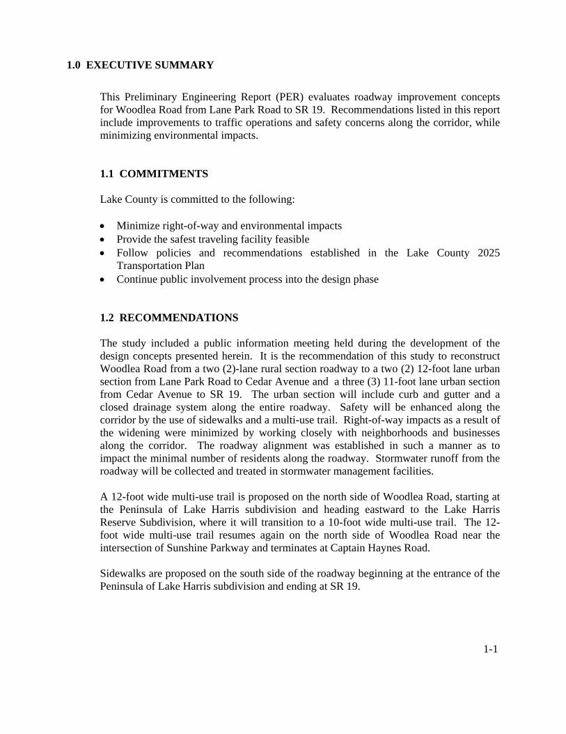
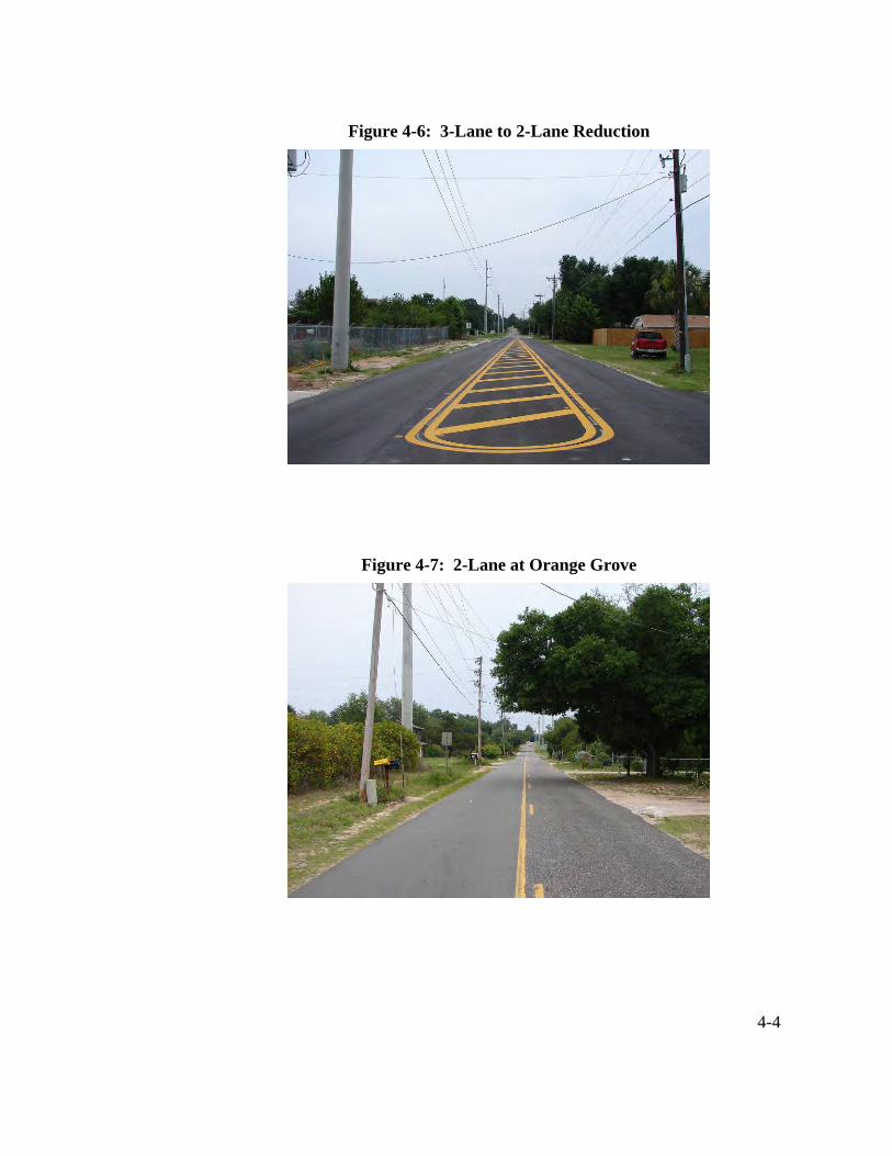
The existing typical section for Woodlea Road is a two-lane, rural facility with unpaved shoulders and shallow swales. The travel lanes are nine (9) feet wide with a left turn lane located at the intersection of SR 19. The existing typical section for Woodlea Road is shown by use of photographs as illustrated in Figures 4-4 through 4-9.
Figure 4-4: Intersection at SR 19
Figure 4-5: 3-Lane Section at SR 19
4-4
Figure 4-6: 3-Lane to 2-Lane Reduction
Figure 4-7: 2-Lane at Orange Grove

4-5
Figure 4-8: 2-Lane at Lake Harris Reserve
Figure 4-9: 2-Lane at Peninsula at Lake Harris
4.1.4 Pedestrian Facilities
Lake County requires new subdivisions to construct sidewalks along roads within the subdivision, and on major street frontages adjacent to these developments. It is the desired objective of the Lake County Public Works Department, the agency responsible for planning pedestrian facilities, to have sidewalk on both sides of all major roads in urban areas.

4-6
There is a limited section of sidewalk within the study limits of Woodlea Road. The existing sidewalk extends from Sunshine Parkway to approximately 60 feet past the intersection of Woodlea Road and State Street. This sidewalk, located outside of the roadway right-of-way on the Waterman Cove property, is along the south side of Woodlea Road. See Figures 4-10 through 4-12.
Figure 4-10: Private Sidewalk near Sunshine Parkway
Figure 4-11: Private Sidewalk on South Side of Woodlea Road

4-7
Figure 4-12: End of Private Sidewalk at State Street
The other section of sidewalk exists near the intersection of Woodlea Road and SR 19. See Figure 4-13. In this commercial area of Woodlea Road, sidewalk exists on both sides of Woodlea Road and extends approximately 600 feet west of SR 19.
Figure 4-13: Sidewalk near SR 19
4-8
4.1.5 Bicycle Facilities
Within the study area, there are no existing bicycle lanes or paved shoulders on Woodlea Road.
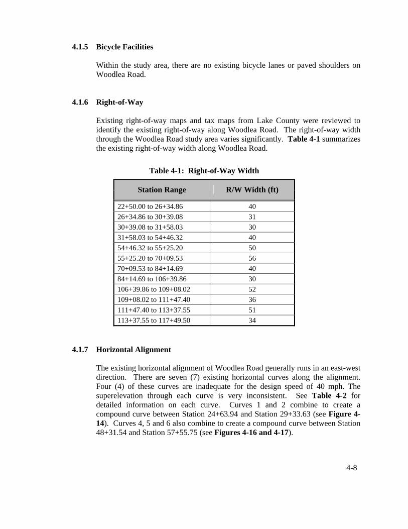
4.1.6 Right-of-Way Existing right-of-way maps and tax maps from Lake County were reviewed to identify the existing right-of-way along Woodlea Road. The right-of-way width through the Woodlea Road study area varies significantly. Table 4-1 summarizes the existing right-of-way width along Woodlea Road.
Table 4-1: Right-of-Way Width
Station Range R/W Width (ft)
22+50.00 to 26+34.86 40 26+34.86 to 30+39.08 31 30+39.08 to 31+58.03 30 31+58.03 to 54+46.32 40 54+46.32 to 55+25.20 50 55+25.20 to 70+09.53 56 70+09.53 to 84+14.69 40 84+14.69 to 106+39.86 30 106+39.86 to 109+08.02 52 109+08.02 to 111+47.40 36 111+47.40 to 113+37.55 51 113+37.55 to 117+49.50 34
4.1.7 Horizontal Alignment
The existing horizontal alignment of Woodlea Road generally runs in an east-west direction. There are seven (7) existing horizontal curves along the alignment. Four (4) of these curves are inadequate for the design speed of 40 mph. The superelevation through each curve is very inconsistent. See Table 4-2 for detailed information on each curve. Curves 1 and 2 combine to create a compound curve between Station 24+63.94 and Station 29+33.63 (see Figure 4-14). Curves 4, 5 and 6 also combine to create a compound curve between Station 48+31.54 and Station 57+55.75 (see Figures 4-16 and 4-17).

4-9
Table 4-2: Summary of Existing Horizontal Curves Curve
PC Sta. PT or PCC Sta.
Curve Radius
(ft)
Curve Length
(ft)
Degree of Curvature
Required Superelevation
(ft/ft)
Existing Superelevation
Range (ft/ft)
Allowable Design Speed (mph)
1 24+63.94 27+33.15 334.21 269.21 17° 08' 37" 0.033 0.019-0.1084 30 2 27+53.96 29+33.63 230.00 179.67 24° 54' 40" 0.02 0.014-0.066 25 3 37+15.30 42+58.09 945.18 542.79 6° 03' 43" Reverse Crown 0.003-0.073 40 4 48+31.54 50+01.47 3510.05 169.93 1° 37' 56" Normal Crown 0.011-0.045 40 5 50+01.47 54+64.39 564.70 462.92 10° 08' 46" 0.020 0.000-0.084 40 6 54+64.39 57+55.75 509.67 291.36 11° 14' 30" 0.025 0.002-0.060 35 7 62+14.44 65+83.53 429.76 369.09 13° 19' 55" 0.039 0.000-0.012 35
Figure 4-14: Curve 1 and Curve 2 looking Westbound

4-10
Figure 4-15: Curve 3 looking Westbound
Figure 4-16: Curve 4, Curve 5 and Curve 6 looking Westbound

4-11
Figure 4-17: Curve 5 and Curve 6 looking Westbound
Figure 4-18: Curve 7 looking Westbound

4-12
4.1.8 Vertical Alignment The vertical alignment along Woodlea Road is relatively consistent for the design speed, with a few irregularities. The terrain is rolling, with grades that range from 0.30 % to 5.0%.
4.1.9 Drainage
4.1.9.1 General Watershed Description Woodlea Road corridor lies within the Lake Harris sub-basin, which is contributory to the Ocklawaha River basin. The project area hydrologic characteristics consist of both ridge and valley landforms, as land elevations range from approximately 68 to 122 feet above sea level. According to the NRCS Soil Survey of Lake County, deep sands characterized by high infiltration rates are found throughout the project site. Hydric soils with low permeability soils are present in flat and depressional areas. There are no existing defined stormwater drainage facilities within the Woodlea Road project study limits. The study corridor is divided to four (4) basins, identified as Basins 100, 200, 300, and 400. See Appendix E for Drainage Maps showing the basin limits.
4.1.9.2 Existing Drainage Basins
Basin 100 Basin 100 is located west of the project, between Station 23+50 (the beginning of the project) and Station 73+80 (east of Sunshine Christian Homes). In general, the existing runoff sheet flows off the project site or is collected via roadside shallow ditches. All collected onsite runoff, as well as approximately 66 acres of offsite runoff, drain in an easterly direction to existing wetlands. A 14”x 23” elliptical pipe (ERCP) cross drain (Station 52+71.40) conveys runoff from the south side of the roadway to the north side. The runoff ultimately drains to Lake Harris (see Figure 4-19). There is an existing closed system along the east of State Street (the Sunshine Christian Homes driveway, Station 55+50). A ditch bottom inlet collects some of the runoff from the existing roadway and offsite area, and discharges to the Sunshine Christian Homes drainage system. The Sunshine Christian Homes system drains to the south, eventually outfalling to a wetland area.
4-13
Figure 4-19: Existing 14”x23” ERCP (Sta. 52+71.40) - Looking South
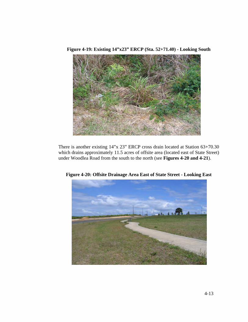
There is another existing 14”x 23” ERCP cross drain located at Station 63+70.30 which drains approximately 11.5 acres of offsite area (located east of State Street) under Woodlea Road from the south to the north (see Figures 4-20 and 4-21).
Figure 4-20: Offsite Drainage Area East of State Street - Looking East

4-14
Figure 4-21: Existing 14”x23” ERCP (Sta. 63+70.30) - Looking North
Basin 200
Basin 200 is located between Station 73+80 and Station 95+50 (east of Captain Haynes Road). Existing roadside shallow ditches intercept all the generated runoff from the roadway, as well as some offsite area. The ditches convey the runoff to the basin low point. There are no existing cross drains within Basin 200.
Basin 300
Basin 300 is located between Station 95+50 and Station 111+30. In general, the existing runoff is collected via roadside shallow ditches and drains to the low area within the basin. There are no existing cross drains within Basin 300.
Basin 400
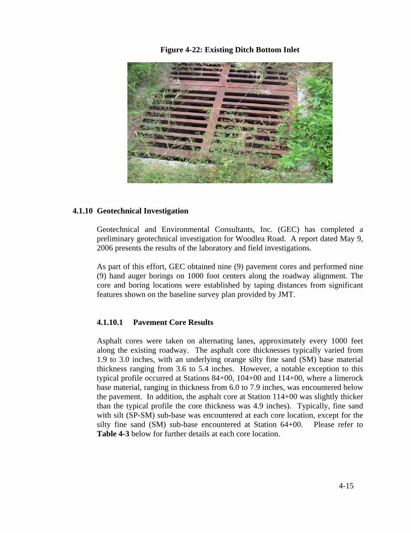
Basin 400 is located between Station 111+30 and Station 117+00 (the end of the project at SR 19). The existing drainage system within this basin consists of roadside shallow ditches, ditch bottom inlets, and pipes (see Figure 4-22). There is an existing closed system within Basin 400 which intercepts the contributing onsite as well as offsite runoff and drains it to the main drainage system on the west side of SR 19.
Offsite Drainage Some of the existing roadway swales receive runoff from offsite areas. As much as practical, the runoff from these offsite areas will be separated from the onsite runoff and discharged directly to the existing outfall.
4-15
Figure 4-22: Existing Ditch Bottom Inlet
4.1.10 Geotechnical Investigation Geotechnical and Environmental Consultants, Inc. (GEC) has completed a preliminary geotechnical investigation for Woodlea Road. A report dated May 9, 2006 presents the results of the laboratory and field investigations. As part of this effort, GEC obtained nine (9) pavement cores and performed nine (9) hand auger borings on 1000 foot centers along the roadway alignment. The core and boring locations were established by taping distances from significant features shown on the baseline survey plan provided by JMT.
4.1.10.1 Pavement Core Results Asphalt cores were taken on alternating lanes, approximately every 1000 feet along the existing roadway. The asphalt core thicknesses typically varied from 1.9 to 3.0 inches, with an underlying orange silty fine sand (SM) base material thickness ranging from 3.6 to 5.4 inches. However, a notable exception to this typical profile occurred at Stations 84+00, 104+00 and 114+00, where a limerock base material, ranging in thickness from 6.0 to 7.9 inches, was encountered below the pavement. In addition, the asphalt core at Station 114+00 was slightly thicker than the typical profile the core thickness was 4.9 inches). Typically, fine sand with silt (SP-SM) sub-base was encountered at each core location, except for the silty fine sand (SM) sub-base encountered at Station 64+00. Please refer to Table 4-3 below for further details at each core location.

4-16
Table 4-3: Asphalt Core Results
Station (*) Offset from CL and Side
(feet)
Asphalt Thickness
(in)
Base Type
Base Thickness
(in)
Sub-base Type
34+00 3 RT 2.5 SM 4.2 SP-SM
44+00 6 LT 2.6 SM 4.8 SP-SM
54+00 6 RT 3.0 SM 3.6 SP-SM
64+00 3 LT 2.8 SM 5.4 SM
74+00 3 RT 2.6 SM 4.8 SP-SM
84+00 6 LT 2.5 Limerock 7.9 SP-SM
94+00 6 RT 2.9 SM 3.6 SP-SM
104+00 3 LT 1.9 Limerock 6.6 SP-SM
114+00 3 RT 4.9 Limerock w/ SM 6.0 SP-SM
*Stations based on Baseline of Survey
4.1.10.2 Description of Subsurface Conditions
The hand auger boring results are shown in Table 4-4. The boring logs describe the soil layers using the Unified Soil Classification System (USCS) symbol (e.g. SP-SM) and ASTM soils descriptions (e.g. sand with silt). Soil classifications and descriptions were based on visual examination.
The boring logs indicate subsurface conditions only at the specific boring locations at the time of the field exploration. Subsurface conditions, including groundwater levels, at other locations along the roadway alignment may differ from conditions encountered at the boring locations. Moreover, conditions at the boring locations can change over time. Groundwater levels fluctuate seasonally, and soil conditions can be altered by earthmoving operations.
The depths and thicknesses of the subsurface strata indicated on the boring logs were interpolated between samples obtained at different depths in the borings. The actual transition between soil layers may be different than indicated. These stratification lines were used for analytical purposes. Earthwork quantity estimates based on the results of the borings will vary from the actual quantities measured during construction.

4-17
4.1.10.3 Soil Strata
In general, the borings typically encountered fine sand (SP) and fine sand with silt (SP-SM) throughout the maximum depths explored. The borings were performed in the right-of-way adjacent to the roadway alignment and therefore no pavement section was encountered at these locations. Specific soil profiles at each boring location are tabulated below in Table 4-4.
Table 4-4: Boring Results
Station (*) Offset from EOP (feet)
Soil Description (USCS Symbol)
Depth (ft)
Encountered Groundwater
Depth (ft)
34+00 14 RT Orangish brown fine sand with silt (SP-SM)
0 - 6 GNE
44+00 14 LT Orangish brown fine sand (SP) 0 - 6 GNE
54+00 14 RT Orangish brown fine sand with silt (SP-SM)
0 - 6 GNE
64+00 14 LT Orangish brown fine sand with silt (SP-SM)
0 - 6 GNE
74+00 14 RT Orangish brown fine sand (SP) 0 - 6 GNE
84+00 19 LT Orangish brown fine sand with silt (SP-SM)
0 - 6 GNE
94+00 14 RT Orangish brown fine sand (SP) 0 - 6 GNE
104+00 14 RT Orangish brown fine sand with silt (SP-SM)
0 - 6 4.6
114+00 17 LT Orangish brown fine sand (SP) 0 - 6 5.3
*Stations based on Baseline of Survey
4.1.10.4 Groundwater Levels
The groundwater surface was identified in the boreholes performed at Stations 104+00 and 114+00 at depths ranging from approximately 4.6 to 5.3 feet below ground surface. Groundwater was not encountered (GNE) in the remainder of the borings performed along the roadway alignment within the depths explored. Depths to groundwater measured at all boreholes are presented in Table 4-4 above.
Groundwater levels can vary seasonally and with changes in subsurface conditions between boring locations. Alterations in surface and/or subsurface

4-18
drainage brought about by site development can also affect groundwater levels. Therefore, groundwater depths measured at different times or at different locations on the site can be expected to vary from those measured by GEC during this investigation.
4.1.11 Accident Data
Accident data for the study area, provided by Lake County Public Works, reflects accidents occurring between January 2002 and February 2006. This data contained a total of 24 accidents. Out of the 24 accidents,
• Thirteen (13) occurred at/near the SR 19 intersection or on SR 19, and were mostly related to careless driving.
• There were four (4) accidents that occurred in parking lots, and had
nothing to do with Woodlea Road.
• There were two (2) accidents referencing Peninsula Drive. One vehicle went off the road along Woodlea road near Peninsula Drive for no apparent reason. The other incident was on Peninsula Drive, where a vehicle hit a mailbox.
• There were five (5) accidents that occurred on Woodlea Road. One of the
accidents was a vehicle striking an animal. The other four (4) accidents were attributed to careless driving.
There are no recommended safety improvements to the roadway based on the evaluation of the accident data. 4.1.12 Intersections and Signalization
There are six (6) intersections within the study area, one (1) of which is signalized (the SR 19 intersection). The current Woodlea Road intersections are as follows:
• The Peninsula at Lake Harris • Waterman Cove – State Street and Sunshine Parkway • Tavares Ridge Blvd. • Cedar Avenue • SR 19
The new development of Lake Harris Reserve will add two new intersections to the study area.
4-19
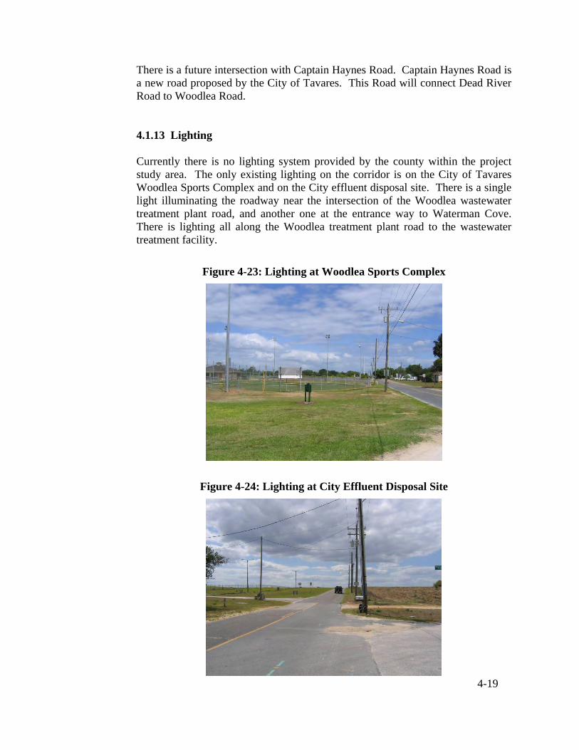
There is a future intersection with Captain Haynes Road. Captain Haynes Road is a new road proposed by the City of Tavares. This Road will connect Dead River Road to Woodlea Road. 4.1.13 Lighting Currently there is no lighting system provided by the county within the project study area. The only existing lighting on the corridor is on the City of Tavares Woodlea Sports Complex and on the City effluent disposal site. There is a single light illuminating the roadway near the intersection of the Woodlea wastewater treatment plant road, and another one at the entrance way to Waterman Cove. There is lighting all along the Woodlea treatment plant road to the wastewater treatment facility.
Figure 4-23: Lighting at Woodlea Sports Complex
Figure 4-24: Lighting at City Effluent Disposal Site

4-20
Figure 4-25: Lighting at Wastewater Treatment Plant Road
Figure 4-26: Lighting at Waterman Cove
4.1.14 Utilities
Woodlea Road has above ground and underground utilities located throughout the project study area. These utilities are both privately and publicly owned. The contacts for these utility owners are shown in Table 4-5.

4-21
Table 4-5: Utility Company Contacts
Utility Company Contact Name Address Phone #
City of Tavares Heath Frederick 201 E. Main Street Tavares, FL 32778 352-742-6222
Progress Energy Florida, Inc.
Rosemary Gruenbaum - Transmission
3300 Exchange Place MAC NP 3B
Lake Mary, FL 32746 407-942-9243
Progress Energy Florida, Inc.
Susan Mendez – Distribution
3250 Bonnett Creek Rd Lake Buena Vista, FL
32830 407-942-9537
Comcast Comm. – CATV Danny Ferguson 8130 CR 44, Leg A
Leesburg, FL 34788 954-534-7380
ext. 146 Sumter Electric
Cooperative, Inc. Bart Bartling 15720 US Highway 441 Eustis, FL 32723
352-793-3801 ext. 1284
Embarq fka Sprint – Florida,
Inc. – Leesburg Doug Van Cleave
425 N. 3rd Street Leesburg, FL 34749-
0048 352-326-1263
City of Leesburg – Electric Jack Rogers
City of Leesburg Electric 2010 W. Griffin Road Leesburg, FL 32742
352-728-9830 ext. 9844
Florida Cable TV Network, Inc. Larry English
P.O. Box 498 23505 S.R. 40
Astor, FL 32102
352-759-2788 352-267-4931
TECO Peoples Gas – Triangle Division Russell Harris 600 W. Robinson Street
Orlando, FL 32801 407-420-6609
Qwest Comm., Inc. George McEvain 1216 SW 6th Avenue Ocala, FL 34474
800-283-4237 303-837-3926
4.1.15 Pavement Conditions
A visual inspection of the pavement was conducted as part of the site visits. The inspection showed that the majority of the pavement was in a fair to poor condition. There was pavement unravelling, transverse and longitudinal cracking and uneven cross slopes observed. Some new asphalt was placed from Cedar Avenue to the Agricultural Center very recently. The westbound lane from the Wastewater Treatment Plant Road to Cedar Avenue appeared in better condition than was observed throughout the project.

4-22
4.2 ENVIRONMENTAL CHARACTERISTICS 4.2.1 Environmental
4.2.1.1 Existing Land Use Existing land use data for Woodlea Road was obtained from recent aerial photography and from site visits. The existing land use is agricultural, residential, City of Tavares utilities, City of Tavares recreational, Lake County government and State government, as well as some minor commercial land use. The beginning half of the project is a combination of orange grove owned by Gorgeous Groves, Inc., and existing and developing residential communities. The second half of the project is dominated by City- and County-owned land and facilities with a mixture of individual residential properties. The very end of the project near SR 19 has some commercial property. The residential communities along Woodlea Road are as follows:
The Peninsula Waterman Cove Lake Harris Reserve Tavares Ridge Individual Residences
Lake Harris Reserve is a new development currently being constructed.
4.2.1.2 Future Land Use According to the City of Tavares Future Land Use Map, the land surrounding the roadway corridor is planned for Suburban Density Residential (SUB), Medium Density Residential (MED), Public Facilities (PUB) and Mixed Use Commercial (MUC).
4.2.1.3 Cultural Features and Community Services Cultural features preserve and enhance the natural aesthetics of a community and include parks and other recreation areas, schools, churches and other religious institutions, and offers neighborhood gathering places. Community services include facilities that provide necessary services such as fire and police stations, hospitals, cemeteries, public buildings, and civic facilities.

4-23
The cultural features and community services for Woodlea Road are listed below:
City of Tavares Woodlea Sports Complex Lake County Agricultural Center Lake County Public Health Unit The National Guard facility Department of Children and Families City of Tavares Wastewater Treatment Plant and Effluent Disposal
facilities Lane Park Cemetery
4.2.2 Economic
There are only two commercial parcels near SR 19 which contain commercial structures. Currently there is a small insurance business on one of the commercial properties. This type of business use is very minor. Gorgeous Groves, Inc. currently has an operational orange grove at the beginning of the project. The agricultural business along this corridor is still very active.
4.2.3 Historical
There are three potential historical resources sites that may be located within the existing Woodlea Road right-of-way. The three sites are not considered to be eligible for listing in the National Register of Historic Places (NHRP). Current data provided by the Florida Division of Historical Resources (DHR) indicates that of the three historical resource sites evaluated, one is located outside of the right-of-way and within the project limits of the Lake Harris Reserve project, and therefore requires no further evaluation. The remaining two sites (8LA2853 and 8LA2854) are reported to have a potential to extend further south from the Lake Harris Reserve project into the existing southern right-of-way of Woodlea Road. See Appendix D for site locations.
4.3 HYDROLOGIC AND NATURAL FEATURES 4.3.1 Hydrogeography
Woodlea Road lies on a peninsula that extends into Lake Harris at its eastern shoreline. Ridges and troughs highlight the geomorphic features and define the natural drainage patterns of this area. Based on topography, it appears as though a large forested wetland complex fringing Lake Harris serves as the collection point for surface water flow for this drainage area.

4-24
4.3.2 Soils The U.S. Natural Resources Soil Conservation Service (NRCS) Soil Survey of Lake County, Florida, classifies the onsite soil units (see Figure 4-27). According to the survey, the site is comprised of the following soils:
• Arents-Urban land complex (3) • Anclote, Myakka and Felda soils, depressional (5) • Candler sand, 0 to 5 percent slopes (13) • Candler-Urban land complex , 0 to 5 percent slopes (14) • Candler sand, 5 to 12 percent slopes (15) • Immokalee sand (25) • Lake sand, 0 to 5 percent slopes (30) • Myakka sand (35) • Tavares sand, 0 to 5 percent slopes (57)
According to the Hydric Soils of Florida Handbook, 3rd ed., Anclote, Myakka and Felda soils, depressional (5) and Myakka sand (35) are hydric soils, while the remaining soils are well-drained, sandy soils that typically do not support wetland communities.

4-25
Figure 4-27: Soils Map

4-26
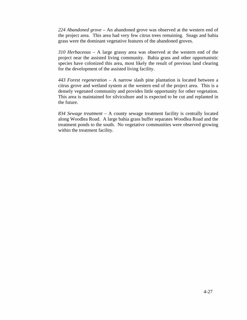
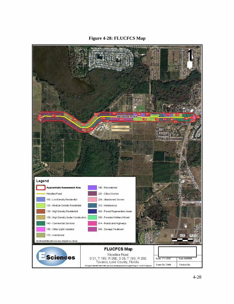
4.3.3 Land Use and Cover The vegetative communities were mapped according to the Florida Land Use, Cover and Forms Classification System (FLUCFCS) and depicted in Figure 4-28. Five vegetative communities were observed within the limits of the project; citrus crop (FLUCFCS 221), abandoned groves (FLUCFCS 224), herbaceous (FLUCFCS 310), forest regeneration (FLUCFCS 443) and forested wetland mixed (FLUCFCS 630). The land use categories include the following: 110 Low density residential – Several homes line the eastern end of the Woodlea Road corridor. These sites are typically 0.5 acres or more in size and are vegetated with bahia grass (Paspalum notatum) and various ornamental plants. 120 Medium density residential – a small subdivision is located at the eastern end of Woodlea Road. These sites are typically vegetated with St. Augustine grass and ornamental plants. 130 High density residential – an assisted living facility is located at the western end of the Woodlea Road project area. This site is paved for parking and vegetated with bahia grass in the open areas. Some aesthetic gardening with ornamental plants was observed. 139 High density under construction – a new multi-unit residential complex is under construction at the western end of Woodlea Road. The land was cleared with active earthmoving equipment present during the field assessment. 140 Commercial and services – Several businesses are located near the intersection of Woodlea Road and SR 19 at the eastern end of the project area. These areas have little landscaping and are primarily paved for parking with some ornamental plants. 170 Institutional – a nursing home is located at the eastern end of Woodlea Road. This facility has some minor landscaping with ornamental plants, as well as paving for parking. 180 Recreational – A county, recreational sports complex is centrally located along Woodlea Road. This facility serves as a baseball park and community center for the surrounding region. Extensive landscape maintenance is performed at this facility. 221 Citrus grove – Several active groves were observed along the Woodlea Road corridor. These groves were maintained for citrus production, which includes trimming, herbiciding and fertilizing.
4-27
224 Abandoned grove – An abandoned grove was observed at the western end of the project area. This area had very few citrus trees remaining. Snags and bahia grass were the dominant vegetative features of the abandoned groves. 310 Herbaceous – A large grassy area was observed at the western end of the project near the assisted living community. Bahia grass and other opportunistic species have colonized this area, most likely the result of previous land clearing for the development of the assisted living facility. 443 Forest regeneration – A narrow slash pine plantation is located between a citrus grove and wetland system at the western end of the project area. This is a densely vegetated community and provides little opportunity for other vegetation. This area is maintained for silviculture and is expected to be cut and replanted in the future. 834 Sewage treatment – A county sewage treatment facility is centrally located along Woodlea Road. A large bahia grass buffer separates Woodlea Road and the treatment ponds to the south. No vegetative communities were observed growing within the treatment facility.
4-28
Figure 4-28: FLUCFCS Map

4-29
4.3.4 Wetlands This section summarizes overall conditions and characteristics of the onsite wetland classification and delineation (i.e. wetland vegetation, soils, and hydrology). The findings are based upon numerous site reviews, examination of historical aerial photography, and review of known documented information for wetlands in Central Florida.
E Sciences evaluated the extent of wetland habitat on the subject site in general accordance with the State Unified Wetland Delineation Methodology (Chapter 62-340 F.A.C.) and the U.S. Army Corps of Engineers (ACOE) Wetland Delineation Manual (1987). The wetland delineation was performed on March 30, 2006 by E Sciences staff to evaluate the extent of jurisdictional wetlands on the subject corridor and was subsequently surveyed by Southeastern Surveying and Mapping Corporation.
Woodlea Road crosses a small segment of a forested wetland mixed system near the western end of the project corridor (see Figure 4-29). This wetland is part of a larger wetland system that acts as a natural surface water conveyance for the surrounding uplands prior to discharging into Lake Harris. The plant community of this system remains intact with some disturbance along the margins. Red maple (Acer rubrum), loblolly bay (Gordonia lasianthus), slash pine (Pinus elliottii), cabbage palm (Sabal palmetto) and laurel oak (Quercus laurifolia) make up the canopy species. Royal fern (Osmunda regalis) and swamp fern (Blechnum serrulatum) make up the dense ground cover stratum. Blackberry (Rubus argutus), Caesar weed (Urena lobata) and elderberry (Sambucus canadensis) have formed a narrow margin around this wetland, which is indicative of disturbance from adjacent land uses. Historically, Woodlea Road was diverted to the south to cross the wetland at its narrowest point. A culvert was placed under the road to maintain the hydrologic connection from the forested wetland to Lake Harris. Additionally, the construction of a new residential community to the north of the project corridor will provide a 50-foot (approximate) buffer from the north edge of the road to the wetland. A 10-foot (approximate) grassy margin provides a narrow buffer between the south edge of Woodlea Road and the wetland.

4-30
Figure 4-29: Wetlands Map

4-31
4.3.5 Regulated Floodplains The evaluation of the floodplains within the Woodlea Road corridor will be conducted in accordance with the requirements set forth in executive order 1198,”Flood Plain Management”, dated May 24,1977. The Federal Emergency Management Agency (FEMA) Flood Insurance Rate Maps (FIRM) for the Lake County community panel numbers 12069C0345D (July 3, 2002), and 12069C0361D (July 3, 2002) will be closely examined for this evaluation.
4.4 THREATENED & ENDANGERED SPECIES The U.S. Fish and Wildlife Service (USFWS), through the Endangered Species Act and other regulatory instruments, and the Florida Fish and Wildlife Conservation Commission (FWC), through Chapter 68 of the Florida Administrative Code (FAC), regulate activities that may affect protected species. The Florida Natural Areas Inventory (FNAI), the USFWS and the FWC databases were reviewed regarding current state and federally listed species that have the potential to occur within the vegetative communities found in Lake County. Based on observations from the site visit, the size and developed condition of this parcel, and its distance from extensive undeveloped lands, the potential for listed species occurrence is low.
According to the FWC data, there were no bald eagle (Haliaeetus leucocephalus) nests located within the immediate vicinity of the Woodlea Road project site. The closest nest was approximately 2,750 feet to the north of the project area along the shore of Lake Harris, resulting in the project area being outside of the nests’ primary and secondary protection zones. The primary zone extends from 0 to 750 feet from the nest, while the secondary zone extends from 750 to 1,500 feet from the nest. During the site visit, no bald eagles were observed at or near the project area.
The corridor was reviewed to evaluate the presence of gopher tortoises (Gopherus polyphemus), a state listed species of special concern and the Florida scrub jay (Aphelocoma coerulescens), a state and federally threatened species. No gopher tortoise burrows were observed within the project limits during the site visit; however, habitat conditions are suitable to support gopher tortoise populations. The habitat conditions and data review of elemental occurrences did not suggest the presence of scrub jays within or proximal to the project area. No other listed species were observed along the corridor. These species include; the limpkin (Aramus guarauna) (state listed as species of special concern). A limpkin colony was documented approximately 1650 feet to the north of the project site, short-tailed snake (Stilosoma extenuatum) (state listed as threatened), Florida bonamia (Bonamia grandiflora) (state listed as endangered, federally listed as threatened) and Britton’s beargrass (Nolina brittoniana) (state and federally listed as endangered). Based on observations from the site visit and research of data from various agencies, the potential for other listed species to occur within the project area is low.

4-32
4.5 CONTAMINATION SITES There are no known contamination sites in the study area.

5-1
5.0 SIGN CONTROLS AND STANDARDS Design and construction criteria for the proposed improvements to Woodlea Road adhere to FDOT and Lake County Standards. Table 5-1 outlines the design criteria used for this study. The following criteria sources are referred in the table: (1) Florida Greenbook, 2005, FDOT; (2) Transportation Planning, Design, and Construction Standards, 2000, Lake County; and (3) Plans Preparation Manual, Vol. I, 2006, FDOT.
5.1 GEOMETRIC DESIGN CRITERIA
Table 5-1: Roadway Design Criteria
Criteria Design Element Mainline
Urban
minor collector (1) Table 3-1 Functional Classification without speed restrictions
Gen
eral
Design Speed 40 mph (1) Table 3-1
Lane Width 11' (Min.) (1) Table 3-7
Min. Queue, Turn Lane 100' (1) Fig. 3-13
Taper Length 80' (1) Fig. 3-13 Brake to Stop 75' (1) Fig. 3-13
Sidewalk Width 6' adjacent to curb; 5' (Min.) (1) Ch.3, P.18-19 (2) II-13
Roadway Cross Slopes 0.02 ft/ft (1) Ch.3, P.16
Clear Zone With 4' (1) Table 3-12
Typ
ical
Sec
tion
Border Width 12'( Min.) (3) P. 2-31 Max. Curvature 10°45' (3) P. 2-50
Min. Radius 535' (3) P. 2-50 Min. Tangent Length 400' (2) P. II-7
Stopping Sight Distance 305' (1) Table 3-6
Hor
izon
tal
A
lignm
ent
Superelevation Rate 0.02 (Min.) to 0.05 (Max.) ft/ft (1) Fig. 3-2
Max. Grade 10% (1) Table 3-4 Max. Change in Grade
(no VC) 0.8 (1) Table 3-5
Min. Grade 0.30% (2) II-8 Ver
tical
A
lignm
ent
Min. K Value (crest and sag) 70’ Crest; 64’ Sag (1) Table 3-6

5-2
Table 5-1A: Multi-Use Trail Design Criteria
Design Element Multi-Use Trail Criteria Source G
ener
al
Design Speed 20 mph (Min.) (1) Ch. 9, P. 7
Multi-Use Trail Width 12' (Min.) (2) II-11
Horizontal Multi-Use Trail Clearance 2' (Min.) (3) P. 8-13
Horizontal Multi-Use Trail Clearance to Roadway 5' (Min.) (3) P. 8-15
Typ
ical
Sec
tion
Cross-Slope 0.02 ft/ft (Max.) (3) P. 8-12
Minimum Radii 95' (3) P. 8-14
Hor
izon
tal
A
li gnm
ent
Stopping Sight Distance 127' (3) P. 8-15
Grades 5 % (Max.) (3) P. 8-13
Ver
tical
Ali g
nmen
t
Minimum Vertical Clearance 8' (1) Ch. 9, P. 6
5.2 DRAINAGE DESIGN CRITERIA The criteria which will be utilized for the design of the stormwater management system will be based on Lake County and St. Johns River Water Management District (SJRWMD) requirements.
5.2.1 Stormwater Management 5.2.1.1 General Design Criteria The stormwater management facilities shall be designed in accordance with Lake County criteria and the regulations outlined by the SJRWMD in the publication “Management and Storage of Surface Waters, Applicant’s Handbook”.

5-3
Woodlea Road is located within Lake Harris sub-basin, which is contributory to the Ocklawaha River Hydrologic basin. Retention/detention facilities with positive outfalls shall be designed to have sufficient storage volume to attenuate of the post-development peak outflow such that it does not exceed the pre-development rate for the following frequency storm events, pursuant to 40C-41.063(2) and 40C-42.025(8), F.A.C.: the mean annual storm (2.3-year frequency), 10-year and 25-year storm events (all 24-hour duration storm events). The 24-hour rainfall depth for the mean annual storm event in Lake County is 4.3 inches.
For retention facilities without positive outlets (i.e., land-locked basins), a 25-year frequency, 96-hour duration storm event shall be used to determine the amount of storage volume required to attenuate the post-development peak outflow such that it does not exceed the pre-development rate for the storm event.
Water Quality (Pollution Abatement)
The quality of stormwater discharging off-site shall meet the surface standards as found in chapter 17-3, F.A.C. (classification for discharge to waters of the state).
Water Quality Volume
Water quality volume shall be provided for the project pursuant to chapter 40C-42, F.A.C. The treatment criteria are outlined in Table 5-2.
Table 5-2: SJRWMD Stormwater Treatment Criteria
CHAPTER 40C-42, F.A.C.
CLASS III RECEIVING WATER TYPE OF TREATMENT SYSTEM
Option No. 1 Off-line treatment
Option No. 2 On-line treatment
RETENTION FACILITY AND EXFILTRATION SYSTEM
0.5 inches of runoff or 1.25 inches times impervious
area, whichever is greater
0.5 inches additional treatment volume over that required in Option No. 1
On-line treatment 1.0 inch of runoff or 2.5 inches times impervious area, whichever is greater
WET DETENTION 14-day residence time (with littoral zone)
21-day residence time (without littoral zone)

5-4
Allowable Water Quality Release Rate
Wet Detention Pond
The allowable draw-down for wet detention pond shall be the first one-half of detention pond volume in the first 24 to 30 hours following a storm event
Dry Detention Pond
The capacity for the specified treatment volume shall be recovered within 72 hours (using factor of safety of at least two) following a storm event.
5.2.1.2 Wet Retention/Detention Facility Design Criteria
The following are some of the criteria which will be utilized to design pond facilities:
• Ponds with positive outlets shall incorporate dimensions no smaller than 2.8 inches in diameter (for a bleed-down orifice) and 20 degrees for a V-notched weir. Pond outfalls shall be located away from the storm sewer system inflow point(s). This serves to minimize “short circuiting” of the pond. The bleed-down invert shall be at or above the estimated wet season water table elevation and above the wet season tailwater elevation. [SJRWMD]
• The outfall structure shall have oil and grease skimmers and baffles or other devices
as necessary to prevent clogging of the bleed-down device. The outlet structure shall be designed to skim floating debris, oil, and grease from an elevation six (6) inches below the surface of the pollution abatement volume elevation to an elevation six (6) inches above the 25-year frequency design high water (DHW) level of the pond. [SJRWMD]
• Proposed pond and roadside ditch slopes, for purposes of public safety, water quality
enhancement and maintenance shall be no steeper than 1:4 (vertical: horizontal) [LC SWMDS V.E. (4)].
• Control elevations shall be no higher than two (2) feet below the minimum road
centerline elevation in the area served by the control device in order to protect roadway subgrade.
• Minimum bottom width for ponds and open channels shall be four (4) feet. [LC
SWMDS V.E. (5)]
• Pond geometric criteria at the control elevation shall be such to maximize the flow path of water from the system inlets to the pond outlet to promote good mixing. Under these design conditions, short circuiting is minimized and pollutant removal efficiency and mixing is maximized. [SJRWMD]

5-5
• The mean depth of the permanent pool shall be between two (2) to eight (8) feet and
the maximum depth shall not exceed twelve (12) feet below the invert of the bleed-down device. [SJRWMD]
• Ditch bottom elevation shall be a minimum of two (2) feet above the seasonal high
water table. [LC SWMDS VI.A. (2)]
• A stabilized entrance driveway from Woodlea Road to the retention/detention facilities will be necessary. This driveway will be a minimum of fifteen (15) feet wide, stabilized to a 12-inch depth, and compacted.
• A maintenance berm shall be required around all retention/detention ponds. This
berm is to be a minimum of twenty (20) feet wide with fencing, or ten (10) feet without fencing. [LC SWMDS V.E. (2)]
• All pond slopes shall be sodded. The slopes (inside) shall be sodded down to the
normal water level. [LC SWMDS V.E. (6)]
• Offsite areas which discharge to or across a site proposed for development must be accommodated in the stormwater management plans for development. The storm water management system development must be capable of transporting existing offsite flows through or around the development without increasing stages or flows upstream or downstream of the development. The estimation of the onsite pre- and post-development flows (i.e., separate offsite and onsite hydrographs must be computed due to the typically significant differences in land use characteristics). [LC SWMDS V.D. (6)]
5.2.2 Hydraulics
• The 10-year frequency storm event, Zone 7, Intensity-Duration-Frequency (IDF)
curve shall be utilized to determine the required storm sewer pipe size to convey the design discharge. [LC SWMDS VI.A. (4)]
• When neglecting minor system losses, hydraulic gradient shall be at least one (1) foot
below the gutter elevation. [LC SWMDS VI.A. (4)]
• The minimum desirable physical velocity shall be 2.0 feet per second when flowing full. [LC SWMDS VI.B. (4)]
• Minimum pipe size for storm sewer systems is 18 inches. [LC SWMDS VI.C. (1)]

5-6
• Maximum storm sewer pipe lengths recommended without access structures are as follows: [LC SWMDS VI.B. (5)]
Pipe Size (Max.) Structure Access Spacing 18 inches 300 feet 24 to 36 inches 400 feet 42 inches and larger 500 feet
• The design frequency for cross drains for projects with a projected 20-year ADT < 1500 and not required for emergency access or evacuation is the 25-year storm event. The design frequency for cross drains for high use or essential roadways, or with a projected 20-year ADT > 1500, is the 50-year storm event. [FDOT Drainage Manual 4.3]
• The acceptable limits of spread for arterial and collector roadways are defined as
one-half of the travelled lane width. [LC SWMDS VI.A. (6)]

6-1
6.0 TRAFFIC
6.1 2025 TRANSPORTATION PLAN Bicycle and sidewalk improvements were identified as needed improvements for Woodlea Road on the Lake-Sumter Metropolitan Planning Organization 2025 Long Range Transportation Plan (2025 Transportation Plan). This plan will guide the transportation system improvements in metropolitan planning areas through the year 2025. The 2025 Transportation Plan identified Woodlea Road to remain as a two lane roadway. 6.2 TRAFFIC ANALYSIS This study is limited to perform engineering analysis and evaluation of the impacts to the study area associated with improvements to Woodlea Road as identified in the 2025 Transportation Plan. Therefore, no traffic analysis was performed for Woodlea Road. However, a traffic analysis was performed for the intersection of Woodlea Road and SR 19. 6.3 INTERSECTIONS The project scope includes an analysis of the traffic flow operating condition and storage length calculations for the intersection of Woodlea Road at SR 19. The analysis was based on traffic counts that were collected in March 2006 for this project. Existing counts were factored up using a three (3) percent annual growth rate to develop projected intersection operational characteristics using the SYNCHRO software for opening year 2011 conditions. Opening year 2011 traffic flow operating characteristics are summarized in Table 6-1. The intersection of Woodlea Road is expected to operate at Level of Service (LOS) B during the opening year 2011 p.m. peak hour. All the approach lanes will operate at volume-to-capacity (V/C) ratios less than one, indicating excess capacity is available. Based on the results of the analysis, we recommend that the existing intersection geometry be maintained. Using the existing intersection geometry, Table 6-2 provides a summary of the queuing conditions as they impact the vehicle storage at their respective turn lanes. The queuing analysis was based on the Red Time Formula that takes into account the green-to-cycle length ratio, percentage of trucks in the traffic stream, cycle length and a traffic surge factor of 1.50 to accommodate surges in vehicular arrivals during the peak hour. As shown in Table 6-2, the eastbound shared left turn/through lane on Woodlea Road approaching SR 19 requires a 150-foot queue length, while the eastbound right-turn lane

6-2
requires 50 feet. The queue length requirements to serve the mainline left-turn movements are 50 feet for the northbound approach, and 25 feet for the southbound approach. It should be noted that these queue lengths can be accommodated within the respective turn lane configurations.
Table 6-1: Intersection analysis of SR 19 at Woodlea Road
Opening Year 2011 P.M. Peak Hour
Volume V/C Delay Approach (vph) Ratio (sec/veh) LOS
Left 10 0.08 9.20 A SB
Through/Right 1697 0.79 19.00 B
Left 39 0.22 17.70 B NB
Through/Right 1650 0.67 8.50 A
Left/Through 93 0.62 72.50 E EB Right 44 0.01 40.30 D
WB Left/Through/Right 10 0.16 55.20 E
Overall Intersection 0.73 15.90 B
Table 6-2: SR 19 at Woodlea Road Queue Length Analysis of Turn Lanes
Year 2011 Opening Year Conditions
Turning Movement
Turning Volume (veh/hr)
G/C Ratio
Total Cycle
Length (sec)
Number of Turn Lanes
Per Lane Volume
(VPHPL)
Percent Trucks
Traffic Surge Factor
Calculated Queue
Length (ft)
Vehicle Queue Length
(ft)
EB Left/Through 103 0.140 140 1 103 5.00% 1.50 136 150
EB Right 44 0.260 140 1 44 5.00% 1.50 50 50
NB Left 39 0.310 140 1 39 5.00% 1.50 41 50
SB Left 10 0.140 140 1 10 5.00% 1.50 13 25

7-1
7.0 PRELIMINARY DESIGN ANALYSIS
7.1 PROJECT SCOPE The Lake-Sumter Metropolitan Planning Organization (MPO) 2025 Long Range Transportation Plan (2025 Transportation Plan) identified bicycle and sidewalk improvements for Woodlea Road. The 2025 Transportation Plan also identified Woodlea Road to remain as a two-lane roadway. This design analysis will evaluate recommended MPO improvements to Woodlea Road, as well as design upgrade improvements. The design upgrade improvements are safety improvements to benefit the traveling public and pedestrians. The evaluation of the design upgrade improvements will be based on compliance with current Lake County design standards. Woodlea Road is currently a two (2)-lane rural section roadway with substandard nine (9)-foot wide travel lanes. It is proposed that Woodlea Road be upgraded to a two (2)-lane urban roadway with curb and gutter and standard lane widths. A sidewalk is to be provided on the south side of the roadway throughout the project. A multi-use trail is to be provided on the north side of the roadway. This multi-use trail is to terminate at Captain Haynes Road. Captain Haynes Road is a new roadway to be constructed by the City of Tavares, and will connect Dead River Road to Woodlea Road. A multi-use trail will be constructed along Captain Haynes Road by the City of Tavares as part of their roadway project. These segments of the multi-use trail are part of an overall master trail plan for the City of Tavares. 7.2 TYPICAL SECTIONS
The development of the typical sections began by addressing the area from the beginning of the project to the future intersection at Captain Haynes Road. This section will contain both a sidewalk and multi-use trail. This typical section will also contain two (2) twelve (12)-foot wide travel lanes with a two (2)-foot curb and gutter on each side. The City of Tavares stated that a twelve (12)-foot multi-use trail is planned for Woodlea Road. This was the same width used for the multi-use trail proposed along Captain Haynes Road. The standard sidewalk width to be used is five (5) feet per Lake County standards. A sixty (60)-foot right-of-way will be required for this typical section in order to fit all of the roadway elements, provide additional space for utilities and tying into existing ground. This typical section will address most of the roadway design from the beginning of the project to Captain Haynes Road (see Figure 7-1).

7-2
Figure 7-1: Typical Section from the beginning of Project to Future Captain Haynes Road
Sta. 22+50.00 to Sta. 39+61.22 and Sta. 70+14.65 to Sta. 91+40.00
At the time of this report, a new development was being constructed called Lake Harris Reserve. Additional right-of-way was provided by this development along the frontage on the north side of Woodlea Road. A multi-use trail, ten (10) feet in width, was constructed by the developer along the frontage of the development. The typical section shown in Figure 7-1 was modified to reflect the additional right-of–way provided as well as the ten (10)-foot multi-use trail (see Figure 7-2).
Figure 7-2: Typical Section at Lake Harris Reserve Sta. 39+61.22 to Sta. 55+30.69

7-3
Directly across from Lake Harris Reserve is a retirement community called Waterman Cove. There is an existing five (5)-foot sidewalk located along the frontage of Waterman Cove on the south side of Woodlea Road, but this sidewalk is located on Waterman Cove property. The design approach in this area is to make use of this existing sidewalk and approach Waterman Cove for an easement - rather than proposing construction of a new sidewalk parallel to, and on the same side of the road as, the Waterman Cove sidewalk,. The typical section in Figure 7-2 was modified to reflect the existing Waterman Cove sidewalk (see Figure 7-3).
Figure 7-3: Typical Section at Lake Harris Reserve Sta. 55+30.69 to Sta. 70+14.65
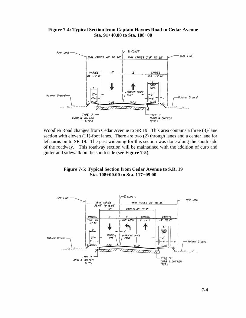
The next area of the project to be addressed was from Captain Haynes Road to SR 19. This section will continue the sidewalk on the south side of the roadway. This typical section will also contain two (2) twelve (12)-foot wide travel lanes with a two (2)-foot curb and gutter on each side. A typical section was developed with variable right-of-way to Cedar Avenue, (see Figure 7-4).
7-4
Figure 7-4: Typical Section from Captain Haynes Road to Cedar Avenue Sta. 91+40.00 to Sta. 108+00
Woodlea Road changes from Cedar Avenue to SR 19. This area contains a three (3)-lane section with eleven (11)-foot lanes. There are two (2) through lanes and a center lane for left turns on to SR 19. The past widening for this section was done along the south side of the roadway. This roadway section will be maintained with the addition of curb and gutter and sidewalk on the south side (see Figure 7-5).
Figure 7-5: Typical Section from Cedar Avenue to S.R. 19 Sta. 108+00.00 to Sta. 117+09.00

7-5
7.3 ALIGNMENT IMPROVEMENTS Since compound curves can mislead a motorist’s expectation of curve radius, the proposed horizontal alignment will eliminate these compound curves with a single curve. Curves 1 and 2 in Table 4-2 will be replaced by Curve 1 in Table 7-1. Curve 1 will provide a consistent design speed of 30 mph and consistent superelevation of 0.038 ft/ft. Curves 4, 5 and 6 in Table 4-2 will be replaced by Curve 3 in Table 7-1. Curve 3 will provide a consistent design speed of 40 mph and superelevation of 0.05 ft/ft. Additional curve improvements will be made to improve the design speeds of the existing curves. Curve 2 in Table 7-1 is very close to the same radius as existing Curve 3 in Table 4-2. Both have a design speed of 40 mph, but the proposed Curve 2 will be improved with a consistent reverse crown superelevation of 0.02 ft/ft. Curve 4 in Table 7-1 will replace existing Curve 7 in Table 4-2, improving the design speed from 35 mph to 40 mph with a superelevation of 0.05 ft/ft. Alignment shifts will be introduced into the proposed alignments to minimize residential property right-of-way impacts and cost to the project. These shifts occur three (3) times along the corridor. The first shift is just east of Lake Harris Reserve and Waterman Cove. An eleven (11)-foot shift to the north from the existing roadway centerline will avoid residential property impacts all the way to future Captain Haynes Road. Another shift in alignment is proposed just east of the future Captain Haynes Road. This shift is five (5) feet to the south of the existing roadway centerline, and is intended to avoid residential property impacts all the way to Cedar Avenue. There will be very minor residential property impacts in the area where the shift transitions from eleven (11) feet north of existing centerline to five (5) feet south of existing centerline. The last shift occurs at Cedar Avenue, where the roadway is shifted back to follow the existing centerline. Curves 5 through 10 are new curves introduced into the alignment to shift the roadway left and right. Table 7-1 is a summary of the proposed alignment curves.

7-6
Table 7-1: Summary of Proposed Horizontal Curves
7.4 RELOCATIONS
No residential or business relocations are anticipated for this project. 7.5 RIGHT-OF-WAY COSTS
The right-of-way (R/W) costs are based on an estimated land value of $50,000.00 per acre. An estimated cost of $80,000.00 per acre was used for properties that could have potential business related costs. See Appendix D for estimated R/W costs. 7.6 CONSTRUCTION COSTS Engineer’s construction cost estimates were generated based on preliminary quantities and historical average unit pricing from the Florida Department of Transportation (FDOT), and can be found in Appendix D.
7.7 PEDESTRIAN / BICYCLE FACILITIES
Bicycle and sidewalk improvements were identified as needed improvements for Woodlea Road on the Lake-Sumter Metropolitan Planning Organization 2025 Long Range Transportation Plan. This project will provide the necessary bicycle facilities through the proposed construction of a multi-use trail on the north side of Woodlea Road
Curve
PC Sta.
PT Sta.
Curve Radius
(ft)
Curve Length
(ft)
Degree of Curvature
Design Superelevation
(ft/ft)
Allowable Design Speed (mph)
1 24+64.57 29+69.63 318.31 505.06 18° 00' 00" 0.038 30
2 37+12.42 42+60.81 954.93 548.38 6° 00' 00" RC 40
3 49+92.45 57+59.86 532.98 767.41 10° 45' 00" 0.05 40
4 61+73.96 66+31.70 532.98 457.74 10° 45' 00" 0.05 40
5 70+64.77 71+81.35 1527.89 116.58 3° 45' 00" NC 40
6 71+81.35 72+82.50 1527.89 101.15 3° 45' 00" NC 40
7 94+50.15 96+08.99 1527.89 158.85 3° 45' 00" NC 40
8 96+08.99 97+67.84 1527.89 158.85 3° 45' 00" NC 40
9 106+25.46 107+12.87 1527.89 87.42 3° 45' 00" NC 40
10 107+12.87 108+00.29 1527.89 87.42 3° 45' 00" NC 40

7-7
from Park Lane Road to the future Captain Haynes Road, where it will connect to another segment of multi-use trail proposed along Captain Haynes Road by the City of Tavares. This project will also provide for pedestrian traffic with the construction of sidewalk from Park Lane Road to SR 19. Pedestrians will also be able to utilize the multi-use trail. 7.8 SAFETY
Safety enhancements along Woodlea Road include a raised curb and gutter adjacent to the sidewalk and multi-use trail, roadway cross slopes, wider roadway pavement and improved curve alignments. 7.9 UTILTIY IMPACTS
Since the roadway will require some shifts in the alignment, reconstruction in the existing curve areas and a closed drainage system, utility impacts will be significant throughout the Woodlea Road corridor. It is anticipated that the following utilities will be relocated:
• Overhead electric distribution lines • Water • Sewer • Telecommunications • Cable
7.10 MAINTENANCE OF TRAFFIC / CONSTRUCTION IMPACTS
An important aspect of the project design will be to develop a safe and effective traffic control plan that allows construction of these improvements while safely maintaining two lanes of traffic (one lane in each direction) through the construction zone at all times. The traffic control plan will meet criteria set forth in the “FDOT Design Standards” 600 series as well as the latest version of the “Manual of Uniform Traffic Control Devices”. 7.11 DRAINAGE 7.11.1 Stormwater Management Alternatives Ponds and Exfiltration Trenches are the two stormwater management alternatives that were evaluated for this project. Each alternative is discussed in greater detail in this section.

7-8
Ponds: Two (2) types of retention/detention ponds are evaluated: Traditional and Joint-Use.
Traditional: This type of pond is constructed, owned and maintained by the County and
accepts only roadway runoff. The ponds can be either wet or dry retention/detention facilities.
Joint-Use: This type of pond combines the stormwater management needs of the
roadway with an adjacent landowner, thereby reducing the total land area required. A joint-use pond is typically constructed by the County, but owned and maintained by the adjacent landowner with the County retaining a permanent drainage easement. These ponds can be either wet or dry retention/detention facilities.
Exfiltration Trenches:
This alternative includes a perforated pipe and gravel envelope located within the roadway right-of-way. Treatment is accomplished through percolation of runoff through the slots and gravel envelope into the shallow groundwater aquifer. Sediment accumulation and clogging can reduce the life of an exfiltration trench. Total replacement of the trench may be the only possible means of restoring the treatment capacity and recovery of the system.
The criteria used for this evaluation included: initial cost, maintenance cost, environmental (i.e., wetland and floodplain) impacts, physical (i.e., impacts to utilities, trees, MOT, etc.) impacts and capabilities (ability to effectively remove pollutants from the runoff). The ‘Initial Cost’ (including property acquisition) was evaluated for each alternative, with the least costly receiving the lowest score and the most costly receiving the highest score. The joint-use ponds are listed before traditional ponds since they will be smaller in size.
The three alternatives were also evaluated based on ‘Maintenance Cost’ over the life of the feature. The exfiltration trenches are listed as the most expensive option since its maintenance cost will significantly increase over time.
‘Public Acceptance’ takes into account possible public resistance to acquiring property for ponds and locating ponds in the vicinity of residential areas. Joint-use ponds were scored higher than traditional ponds since the joint-use ponds would be smaller in size.
‘Physical Impacts’ include impacts to utilities, trees, maintenance of traffic, etc. The two pond alternatives were given the same score since they are both outside of the roadway right-of-way.

7-9
Table 7-2 summarizes the stormwater management alternatives. The preferred stormwater management alternative is the joint-use pond. If a joint-use pond opportunity is not available, the traditional pond site is the second preferred stormwater management alternative. If pond sites are not available, then the exfiltration trench should be considered.
Table 7-2: Stormwater Management System Alternative Evaluation
* Preferred alternative
7.11.2 Pond Siting Analysis Several site visits were conducted to assess the potential pond locations. The following parameters of each site were analyzed in the selection process:
• Size • Hydraulics • Type of Soils • Proximity to Outfall • Ground Elevation/Water Table • Wetland Area • Market Availability • Accessibility • Approximate Land Cost • Contamination Assessment
Ponds
Evaluation Criteria
Traditional Joint-Use
Exfiltration
Trench
Initial Cost 4 6 2
Maintenance Cost 6 9 1
Public Acceptability 5 6 9
Environmental Impacts 1 3 9
Physical Impacts 6 9 1
Capabilities 9 9 4
Total Score
31
42*
26

7-10
The following pages give a brief discussion of the sites for retention/detention ponds in Basins 100 through 400.
Basin 100 Basin 100 is located west of the project, between Station 23+50 (the beginning of the project) and Station 73+80 (east of Sunshine Christian Homes). The Basin 100 area is 7.78 acres (Ac), excluding the contributing offsite and pond area.
TOTAL ONSITE DRAINAGE AREA (DA) = 7.78 Ac
IMPERVIOUS AREA = 4.84 Ac PERVIOUS AREA = 2.94 Ac REQUIRED POND AREA = 1.5 Ac
TOTAL OFFSITE DRAINAGE AREA (DA) = 77.80 Ac
Figure 7-6: Pond 1 Site - Looking South

7-11
Pond 1 The Pond 1 location is an irregular shaped parcel located southwest of the project (see Appendix E). The terrain of this basin slopes from a high of approximately elevation 121.40 (at west end of the project) to a low of approximately elevation 68.26 (at Station 52+20). The proposed Pond 1 site is located at the lowest area within the Basin 100, and is adjacent to the wetlands and canal south of the Woodlea Road. An existing 14” x 23” elliptical pipe cross drain conveys collected runoff from south of the roadway to the north, ultimately discharging to Lake Harris. The existing pipe will be evaluated structurally and hydraulically, and will be replaced if it is necessary. Pond 1 will be designed as a wet retention/detention pond with an outfall which will discharge to the adjacent wetlands and canal. According to the Flood Insurance Rate Map, Pond 1 site is not located within the floodplain. The soil within this pond site has been mapped by the NRCS as Candler Sand (hydrologic soil group ‘A’). The aforementioned pond will be designed using Lake County and SJRWMD criteria which apply to “Watersheds with Positive Outlets”. Pond 1 will be designed to provide treatment and attenuation for Basin 100 onsite only. The contributing offsite drainage area will be intercepted by the proposed offsite ditches adjacent to the right-of-way, and will be discharged to the outfall where feasible.
Figure 7-7: Wetlands Adjacent to Pond 1 Site – Looking South

7-12
Basin 200
Basin 200 is located between Station 73+80 and Station 95+50 (east of Captain Haynes Road). The Basin 200 area (onsite) is 3.10 Ac, excluding the contributing offsite and pond area.
TOTAL ONSITE DRAINAGE AREA (DA) = 3.10 Ac
IMPERVIOUS AREA = 1.91 Ac
PERVIOUS AREA = 1.19 Ac
TOTAL OFFSITE DRAINAGE AREA (DA) = 7.70 Ac
Pond 2 (Joint-Use)
There is a City of Tavares roadway project within the Basin 200, the proposed Captain Haynes Road located north of Woodlea Road (Station 91+90, Lt.). Captain Haynes Road will be a City-owned and maintained road. The Captain Haynes Road drainage report accounted for some drainage area contributing from Woodlea Road, and City’s proposed ponds were designed to provide treatment as well as attenuation according to the Lake County and SJRWMD criteria. According to the Captain Haynes Road drainage report, area contributing from Woodlea Road is as follows:
Impervious Area (according to the drainage report) = 1.55 Ac @ CN = 98
Pervious Area (according to the drainage report) = 4.92 Ac @ CN = 39
Total Area = Onsite + Offsite Areas
Total Area = 6.47 Ac @ CN =53.13
According to the JMT preliminary drainage calculations, the contributing drainage area from the Woodlea Road project to the Captain Haynes Road project (Station 73+80 to Station 95+50) is as follows:
Onsite Drainage Area (DA) = 3.10 Ac
Impervious Area (according to the preliminary plans) = 1.91 Ac @ CN = 98
Pervious Area (according to the preliminary plans) = 1.19 Ac @ CN = 49
Offsite Area (according to the 5’ contour map) = 7.70 Ac @ CN = 49
Total Area = Onsite + Offsite Areas
Total Area = 3.10 Ac + 7.70 Ac = 10.80 Ac @ CN =57.70

7-13
The Captain Haynes Road project proposed two ponds, one dry (City Pond 1) and the other wet pond (City Pond 2). City Pond 1 receives runoff from Woodlea Road and other sub-basins. According to the Captain Hynes Drainage Report, City Pond 1 will not provide sufficient treatment volume for the contributing drainage area and compensatory treatment is proposed to be provided within City Pond 2. JMT will model all the routings and investigate possibility of using the City’s ponds without any or minimum modification to meet Lake County and SJRWMD criteria.
Basin 300 Basin 300 is located between Station 95+50 and Station 111+30. The Basin 300 area is 1.66 Ac, excluding the contributing offsite and pond areas.
TOTAL ONSITE DRAINAGE AREA (DA) = 1.66 Ac
IMPERVIOUS AREA = 1.35 Ac
PERVIOUS AREA = 0.31 Ac
REQUIRED POND AREA = 1.2 Ac
TOTAL OFFSITE DRAINAGE AREA (DA) = 91.1 Ac
Figure 7-8: Pond 3– Looking South
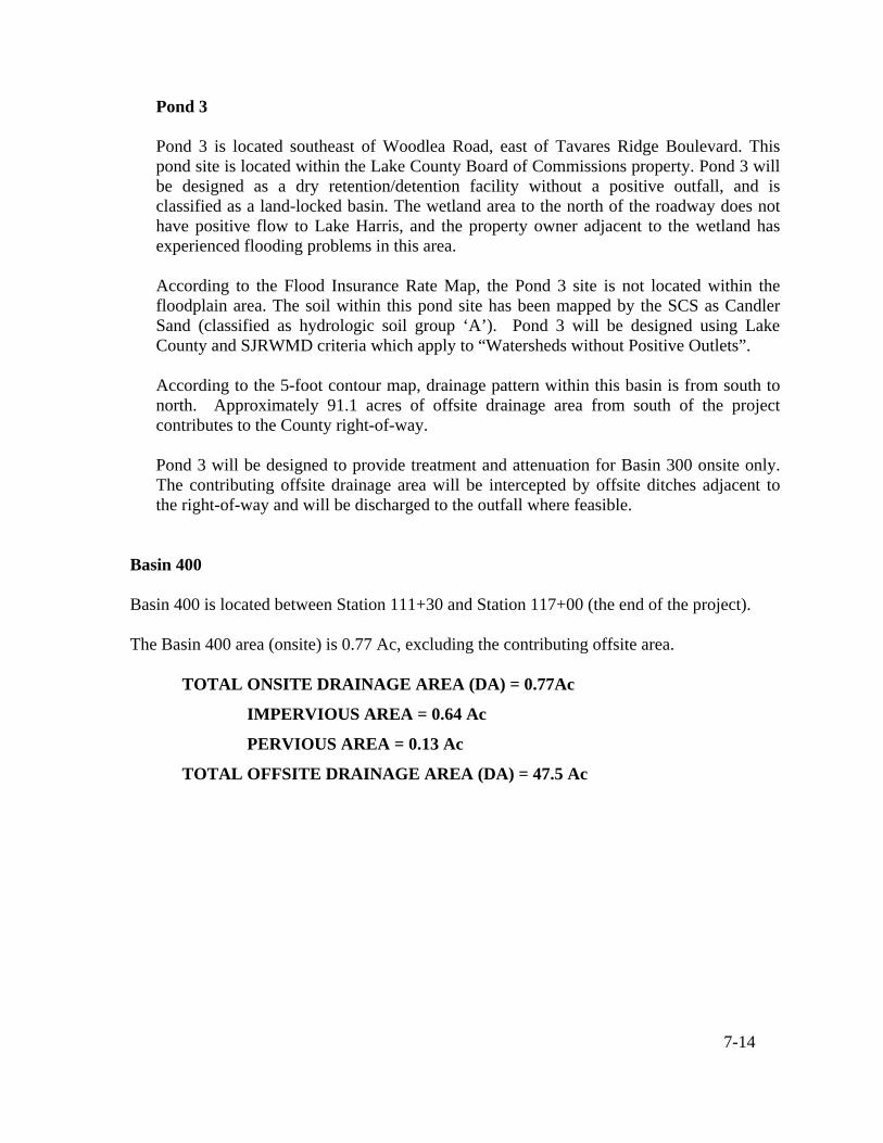
7-14
Pond 3
Pond 3 is located southeast of Woodlea Road, east of Tavares Ridge Boulevard. This pond site is located within the Lake County Board of Commissions property. Pond 3 will be designed as a dry retention/detention facility without a positive outfall, and is classified as a land-locked basin. The wetland area to the north of the roadway does not have positive flow to Lake Harris, and the property owner adjacent to the wetland has experienced flooding problems in this area. According to the Flood Insurance Rate Map, the Pond 3 site is not located within the floodplain area. The soil within this pond site has been mapped by the SCS as Candler Sand (classified as hydrologic soil group ‘A’). Pond 3 will be designed using Lake County and SJRWMD criteria which apply to “Watersheds without Positive Outlets”.
According to the 5-foot contour map, drainage pattern within this basin is from south to north. Approximately 91.1 acres of offsite drainage area from south of the project contributes to the County right-of-way.
Pond 3 will be designed to provide treatment and attenuation for Basin 300 onsite only. The contributing offsite drainage area will be intercepted by offsite ditches adjacent to the right-of-way and will be discharged to the outfall where feasible.
Basin 400 Basin 400 is located between Station 111+30 and Station 117+00 (the end of the project). The Basin 400 area (onsite) is 0.77 Ac, excluding the contributing offsite area.
TOTAL ONSITE DRAINAGE AREA (DA) = 0.77Ac
IMPERVIOUS AREA = 0.64 Ac
PERVIOUS AREA = 0.13 Ac
TOTAL OFFSITE DRAINAGE AREA (DA) = 47.5 Ac

7-15
Figure 7-9: Existing FDOT Pond - Looking South
The existing drainage system within this basin consists of roadside shallow ditches, ditch bottom inlets, and pipes. There is an existing closed system located south of Basin 400, which intercepts the contributing onsite as well as offsite runoff and conveys it to the main drainage system running along the west side of SR 19. The existing storm sewer system will be evaluated and modified to collect the proposed runoff within Basin 400. A FDOT connection permit may be required to ensure that the discharge to the FDOT storm drain system will not be increased.
Figure 7-10: Existing Ditch Bottom Inlet

7-16
Figure 7-11: Roadside Shallow Swales – Looking West
7.12 LANDSCAPING
Landscaping is not proposed on the Woodlea Road corridor. 7.13 LIGHTING
Lighting is not proposed for the Woodlea Road corridor, other than maintaining the existing lighting at the Sports Complex and Waterman Cove entrances.
7.14 ENVIROMENTAL IMPACTS 7.14.1 Cultural Resource Impacts
In consideration of the two potential historical resource sites that may extend into the Woodlea Road right-of-way at the Lake Harris Reserve development, it is recommended that a professional archaeological survey be conducted during final design to determine the extent of these historical resource sites within the Woodlea Road corridor.
7.14.2 Socio-Economic Impacts
There are no socio-economic impacts anticipated for the facilities located on this corridor as a result of the proposed improvements.

7-17
7.14.3 Wetland Impacts
Woodlea Road crosses a small segment of a forested wetland system at its narrowest point. A culvert was placed under the road to maintain the hydrologic connection from the forested wetland to Lake Harris. It is anticipated that the extension of this cross drain will cause minor impacts to the wetland system.
7.14.4 Threatened and Endangered Species Impacts
The potential impacts to listed threatened and endangered species to occur within this project is very low.
7.14.5 Contamination Impacts
The evaluation of potential contamination impacts was not part of the scope of services for this project.
7.14.6 Tree Impacts
Very minor impacts to trees will occur as a result of this project. There are an estimated total of eight (8) trees that will be impacted.
7.15 RESULTS OF PUBLIC INVOLVEMENT
During the course of this study a public information meeting was held on August 1, 2006. The following are the most significant issues raised by the residents and meeting attendees during the development of the study.
• Multi-use trail extension to SR 19 (there was also opposition to this request);
• Collection of roadway drainage currently draining onto the Hyde property at 12301 Woodlea Road;
• Development of a school bus stop at the Woodlea Road/Tavares Ridge Boulevard
intersection; and
• Driveway vehicle access requests. The issues highlighted above will be considered and implemented as determined feasible in the final design.

8-1
8.0 CONCLUSIONS AND RECOMMENDATIONS Based on the foregoing sections of this report, a series of conclusions and recommendations for the future improvements to Woodlea Road have been formulated concerning the roadway typical section, the roadway horizontal and vertical alignment, intersection configurations and drainage concepts. It is the recommendation of this study to reconstruct Woodlea Road from a two (2)-lane rural section roadway to a two (2) 12-foot lane urban section from Lane Park Road to Cedar Avenue and a three (3) 11-foot lane urban section from Cedar Avenue to SR 19. The urban section will include curb and gutter and a closed drainage system along the entire roadway. Safety will be enhanced along the corridor by the use of sidewalks and a multi-use trail. Right-of-way impacts as a result of the widening will be minimized by working closely with neighborhoods and businesses along the corridor. The roadway alignment was established in such a manner as to impact the minimal number of residents along the roadway. Stormwater runoff from the roadway will be collected and treated in stormwater management facilities.
While there are no existing bicycle lanes or paved shoulders on Woodlea Road, bicycle and pedestrian facilities will be incorporated into the project improvements. A 12-foot wide multi-use trail is proposed on the north side of Woodlea Road, starting at the Peninsula of Lake Harris subdivision and heading eastward to the Lake Harris Reserve Subdivision, where it will transition to a 10-foot wide multi-use trail. The 12-foot wide multi-use trail resumes again on the north side of Woodlea Road near the intersection of Sunshine Parkway and terminates at Captain Haynes Road. Sidewalks are proposed on the south side of the roadway beginning at the entrance of the Peninsula of Lake Harris subdivision and ending at SR 19. Community input obtained from the public involvement process will be evaluated and incorporated into the final design where feasible.

APPENDIX A
PLAN / PROFILE EXHIBITS

APPENDIX B
PUBLIC MEETING MINUTES

APPENDIX C
PROJECT CONSTRUCTION COST ESTIMATE
& R/W COST ESTIMATE

APPENDIX D
HISTORICAL RESOURCE SITES

APPENDIX E
DRAINAGE MAPS

1