Embed Size (px)
Citation preview

©2013-2014 DJI Innovations. All Rights Reserved.
WooKong-M Quick Start Guide V 1.14
November 24, 2014 Revision
For Firmware Version V5.26
& PC Assistant Software V2.04
&WM Assistant V1.4.25
Please strictly follow these steps to mount and connect the autopilot system on your multi-rotor, as well as to install
the Assistant Software on your computer or Mobile Device.
Thank you for purchasing this DJI product. Please regularly visit the WooKong-M web page at www.dji.com. This
page is updated regularly. Any technical updates and manual corrections will be available on this web page. Due to
unforeseen changes or product upgrades, the information contained in this manual is subject to change without
notice.
This manual is only for basic assembly and configuration; you can obtain more details and advanced instructions
when using the assistant software. To assure you have the latest information, please visit our website and download
the latest manual and current software version.

©2013-2014 DJI Innovations. All Rights Reserved.2 |
Content
CONTENT ........................................................................................................................ 2
TRADEMARK .................................................................................................................. 3
DISCLAIMER & WARNING ............................................................................................... 4
CERTIFICATIONS ............................................................................................................. 4
SYMBOL INSTRUCTION ................................................................................................... 4
ASSEMBLY &CONFIGURATION ........................................................................................ 5
STEP1 ASSEMBLY ................................................................................................................ 5
STEP2 SOFTWARE AND DRIVER INSTALLATION ON A PC ...................................................... 7
STEP3 CONFIGURATION BY ASSISTANT SOFTWARE ON A PC ............................................... 7
STEP4 COMPASS CALIBRATION .......................................................................................... 8
BASIC FLYING TEST .......................................................................................................... 9
STEP1 ABOUT THE CONTROL MODE SWITCH ...................................................................... 9
STEP2 START & STOP MOTOR ............................................................................................ 9
SETP3 CHECKING LIST BEFORE FLYING ............................................................................... 9
ADVANCED FUNCTIONS ................................................................................................ 11
A1 CONTROL MODE KNOWLEDGE .................................................................................... 11
A2 START & STOP MOTOR KNOWLEDGE .......................................................................... 12
A3 INTELLIGENT ORIENTATION CONTROL (IOC) FLIGHT (WITH GPS MODULE) ................. 13
A4 FAILSAFE ................................................................................................................... 17
WM ASSISTANT FOR MOBILE DEVICE ............................................................................ 20
STEP1 ASSEMBLE THE LED BLUETOOTH MODULE .............................................................. 20
STEP2 WM ASSISTANT INSTALLATION............................................................................... 20
STEP3 PARAMETER CONFIGURATION PROCEDURES .......................................................... 20
STEP4 FLYING TEST PROCEDURES .................................................................................... 21
FORGOT MAIN CONTROLLER PASSWORD ......................................................................... 21
HOW TO ACTIVATE MORE FUNCTIONS ............................................................................. 21
APPENDIX ..................................................................................................................... 22
FIRMWARE & ASSISTANT SOFTWARE UPGRADE ................................................................. 22
PORT DESCRIPTION .......................................................................................................... 23
©2013-2014 DJI Innovations. All Rights Reserved.3 |
LED DESCRIPTION ........................................................................................................... 24
SPECIFICATIONS ............................................................................................................... 25
FAQ .............................................................................................................................. 26
FIX THE TBE (TOILET BOWL EFFECT) PROBLEM ................................................................ 26
REINSTALL THE GPS IN AN OFFSETTING ANGLE ................................................................ 26
ATTITUDE CONTROLLABLE WHEN ONE MOTOR OUTPUT IS FAILED ................................... 26
FLIGHT RESTRICTION IN SPECIFIED AREA DESCRIPTION ..................................................... 27
ABNORMAL CASES IN MOTOR TEST .................................................................................. 27
SOLUTION FOR LED YELLOW AND GREEN BLINKING .......................................................... 27
SOLUTIONS FOR FAILED GAIN VALUE ADJUSTMENT IN THE ASSISTANT SOFTWARE ............... 28
CE STATEMENT.............................................................................................................. 29
Trademark DJI and WooKong-M are registered trademarks of DJI Innovations. Names of product, brand, etc., appearing in this
manual are trademarks or registered trademarks of their respective owner companies. This product and manual are
copyrighted by DJI Innovations with all rights reserved. No part of this product or manual shall be reproduced in
any form without the prior written consent or authorization of DJI Innovations. No patent liability is assumed with
respect to the use of the product or information contained herein.
©2013-2014 DJI Innovations. All Rights Reserved.4 |
Disclaimer & Warning Please read this disclaimer carefully before using the product. By using this product, you hereby
agree to this disclaimer and signify that you have read them fully.
THIS PRODUCT IS NOT SUITABLE FOR PEOPLE UNDER THE AGE OF 18.
WooKong-M is an autopilot system designed for serious multi-rotor enthusiasts providing excellent self-leveling
and altitude holding, which completely takes the stress out of flying RC multi-rotors for both professional and
hobby applications. Despite the product having a built-in autopilot system and our efforts in making the operation
of the controller as safe as possible when the main power battery is connected, we strongly recommend users to
remove all propellers when calibrating and setting parameters. Make sure all connections are good, and keep
children and animals away during firmware upgrade, system calibration and parameter setup. DJI Innovations
accepts no liability for damage(s) or injuries incurred directly or indirectly from the use of this product in the
following conditions:
1. Damage(s) or injuries incurred when users are drunk, taking drugs, drug anesthesia, dizziness, fatigue, nausea
and any other conditions no matter physically or mentally that could impair your ability.
2. Damage(s) or injuries caused by subjective intentional operations.
3. Any mental damage compensation caused by accident.
4. Failure to follow the guidance of the manual to assemble or operate.
5. Malfunctions caused by refit or replacement with non-DJI accessories and parts.
6. Damage(s) or injuries caused by using third party products or fake DJI products.
7. Damage(s) or injuries caused by mis-operation or subjective mis-judgment.
8. Damage(s) or injuries caused by mechanical failures due to erosion, aging.
9. Damage(s) or injuries caused by continued flying after low voltage protection alarm is triggered.
10. Damage(s) or injuries caused by knowingly flying the aircraft in abnormal condition (such as water, oil, soil,
sand and other unknown material ingress into the aircraft or the assembly is not completed, the main
components have obvious faults, obvious defect or missing accessories).
11. Damage(s) or injuries caused by flying in the following situations such as the aircraft in magnetic interference
area, radio interference area, government regulated no-fly zones or the pilot is in backlight, blocked, fuzzy
sight, and poor eyesight is not suitable for operating and other conditions not suitable for operating.
12. Damage(s) or injuries caused by using in bad weather, such as a rainy day or windy (more than moderate
breeze), snow, hail, lightning, tornadoes, hurricanes etc.
13. Damage(s) or injuries caused when the aircraft is in the following situations: collision, fire, explosion, floods,
tsunamis, subsidence, ice trapped, avalanche, debris flow, landslide, earthquake, etc.
14. Damage(s) or injuries caused by infringement such as any data, audio or video material recorded by the use
of aircraft.
15. Damage(s) or injuries caused by the misuse of the battery, protection circuit, RC model and battery chargers.
16. Other losses that are not covered by the scope of DJI Innovations liability.
Certifications This product is approved with quality standards such as CE, FCC and RoHS.
Symbol Instruction
Forbidden(Important)
Cautions
Tip
Reference

©2013-2014 DJI Innovations. All Rights Reserved.5 |
Assembly &Configuration Step1 Assembly
Install the autopilot system and receiver to the aircraft, and connect them according to the following diagram.
Refer to the Port Description for more details.
R/C System· These are example connections.
Please setup Aileron, Elevator,
Throttle, Rudder channels on
your TX first, and choose one 2
or 3 positions switch/channel as
control mode switch, then
connect your receiver to the
right ports on MC.
R/C Receiver(JR)
AUX2
RUDD
THRO
AILE
ELEV
AUX2
R/C Receiver(Futaba / Hitec)
1
234
7
Futaba
S-Bus/S-Bus2S-Bus/S-Bus2
Battery
接电调/云台
IMU· The IMU is best positioned near the
multi rotor’s center of gravity, where
vibration is relatively low.
· Orient the IMU such that the arrow
marked on the printed surface of the
IMU faces the sky and points
directly forward, backward, left or
right.
· The sides of the IMU should be
precisely parallel to the multi rotor
body. Use double-sided foam tape
for secured installation.
Main Controller· There is no orientation requirement for the Main
Controller. Choose a mounting location where as
shorter ESC extension wires are needed as
possible. Please make sure all ports are accessible
when installing the MC so as to facilitate wiring and
software configuration.
· In three-pin ports, pins near the nicks are signal
pins.
· After choosing a location to mount the MC, it is
recommended that you DO NOT mount the MC
until all wirings and software configurations are
completed.
ESC & Motor· Please make sure you are using the ESCs and motors recommended by the
manufacturer of your multi rotor first. We recommend you use DJI motors and ESCs.
WKM output is 400Hz refresh frequency.
· Connect all ESCs to MC by the motor numbering method introduced in Multi-Rotors
Supported .
· If you use 3rd party ESCs, please make sure the ESCs travel midpoint is at 1520us.
DO NOT use 700us travel midpoint ESC, as it may lead aircraft to fly away or cause
injury and damage. After connect ESCs, calibrate ESCs one by one through the
receiver directly before connect them to your MC, Make sure program all of them into
Governor off, Break off and Normal Start up to get best experience.
· If you use 3rd party ESCs, please cut the red wire (power wire) of your ESCs , as the
power from V-SEN on PMU is suitable to most of receivers and other electronic
devices.
· If you use extra BEC, please use a servo cable without power wire to connect V-SEN
to X1. (Not recommend)
LED Indicator· Place The LED indicator
at an appropriate
location of craft body far
away from the GPS. Do
not mount it on other
electronic devices.
· Make sure You can see
the light during the flight.
· You can connect LED to
the CAN-Bus port on
GPS connection wire.
· Please refer to the "LED
Description" in the
Appendix to know the
details of LED blinking
method.
PMU & Battery· There is no requirement for
PMU mounting.
· Use our PMU Connecter (red
line depicts in figure) to connect
battery, PMU and ESCs.
· You can choose 2S-6S LiPo
battery.
GPS/COMPASS· GPS/Compass is sensitive to magnetic interference, should be far away
from any electronic devices.· You should use epoxy resin AB glue to assemble the GPS bracket first as
the figure showed in previous page. · Mount the bracket on the center plate of craft first, then fix the GPS on
the plate of the bracket (by 3M glue provided). The GPS is sensitive to vibration interference, so position the bracket at least 10 cm from any rotor.
ESC
R/C ReceiverPPM PPM
M6M5M4M3M2M1M8M7
PitchF1
F2
Roll
The DJI logo marked on the GPS should face the sky, with the orientation arrow pointing directly forward. The GPS/Compass is packaged with a special indication line for mounting for the first time.If you are uncertain whether materials near the GPS/Compass module are magnetic or not, you can use a compass or magnet to check it. If you use your own mounting rod, make sure it is NOT magnetic!
For safety reason, please
disconnect ESCs and battery
connecter during the firmware
upgrade and configuration
procedure.
Sufficient air flow over the
PMU is highly recommended.
DO NOT cover the ventilation
holes, keep them unobstructed.
DO NOT mount the IMU upside-
down.
Check the double faced adhesive
tape regularly to ensure that the
IMU is securely positioned.
The IMU module is NOT water-
proof or oil-proof.

©2013-2014 DJI Innovations. All Rights Reserved.6 |
Quad-rotor I Quad-rotor X Hexa-rotor I
Hexa-rotor V
Octo-rotor I Octo-rotor VOcto-rotor X
Hexa-rotor IY Hexa-rotor Y
Multi-Rotors Supported
To coaxial propellers: Blue propeller is at Top; Red propeller is at Bottom. Otherwise all
propellers are at top.
Please select the Mixer type in the assistant software according to your aircraft.

©2013-2014 DJI Innovations. All Rights Reserved.7 |
Step2 Software and Driver Installation on a PC
1. Please download the drive installer and the assistant software from DJI website.
2. Connect the autopilot system and the PC via a USB cable, and power on the autopilot system.
3. Run the driver installer, and follow the instructions strictly to finish installation.
4. Run the assistant software installer, and follow the instructions strictly to finish installation.
Step3 Configuration by Assistant Software on a PC
1. Power on the PC. Make sure your computer is connected to the Internet for the first time you use.
2. Switch on the transmitter first, and then power on the autopilot system. Connect the autopilot system to
the PC with a Micro-USB cable. DO NOT break the connection until setup is finished.
3. Run the Assistant Software.
4. Observe the indicators on the left bottom of the software. ( connection indicator and
communication indicator) If the connection indicator is communication indicator is blinking, that the
software is ready, please go to next step.
5. Select the “Info” option. Check the software and the firmware version.
6. Select the “Basic” option. Please follow step-by-step for your first-time-configuration. Basic configuration
is necessary, including Mixer Type, Mounting, RC, and Gain settings.
7. You can click the “Advanced” option for more parameter settings. Advanced setting is optional. There are
settings of Motor, FailSafe, Intelligent Orientation Control (IOC), Gimbal, Low-Voltage Alert, and Flight
Limits. Read the instruction in the assistant software to obtain more details.
8. Select the “Viewer” option and check all parameters.
You may be required to fill register information for your first-time-usage.
If the communication indicator is , please double check the connections.
Basic configuration is necessary before you go to the “Basic Flying Test”.
If the software and the firmware upgrade are available, please upgrade the assistant software
and the firmware by referring to the Appendix.
This step is required to use together with the assistant software to obtain more details.
Recommended Settings for the users with F450/F550/S800/Z15.
Configuration Information Basic Attitude
Motor ESC Propeller Battery Weight Pitch Roll Yaw Vertical Pitch Roll
F450 DJI-2212 DJI-30A DJI-8 Inch 3S-2200 890 g 150 150 100 105 150 150
F550 DJI-2212 DJI-30A DJI-8 Inch 4S-3300 1530 g 170 170 150 140 170 170
S800 DJI-4114 DJI-40A DJI-15Inch 6S-15000 4770 g 200 200 195 175 190 190
S800+Z15 DJI-4114 DJI-40A DJI-15Inch 6S-10000 6100 g 240 240 200 200 220 220
S800 EVO DJI-4114 PRO DJI-40A DJI-15 Inch 6S-15000 6700 g 130 130 150 150 180 180
*S800 with damping kit can use the same values as S800 EVO.

©2013-2014 DJI Innovations. All Rights Reserved.8 |
Step4 Compass Calibration
Without GPS module, please skip this step. If you use with GPS module, follow step-by-step for calibration.
DO NOT calibrate your compass where there is strong magnetic interference, such as
magnetite, car park, and steel reinforcement under the ground.
DO NOT carry ferromagnetic materials with you during calibration, such as keys or cell phones.
Compass module CANNOT work in the polar circle.
Calibration Procedures
1. Quickly switch the control mode switch from GPS Mode to Manual Mode and back to GPS Mode for 6 to
10 times. The LED indicator will turn on solid BLUE.
2. Rotate your Multi-rotor around the horizontal axis (about 360o) until the LED changes to solid GREEN,
and then go to the next step.
3. Hold your Multi-rotor vertically and rotate it (its nose MUST be downward) around the vertical axis (about
360o) until the LED turns off, meaning the calibration is finished.
4. The LED indicator will show whether the calibration is successful or not.
If the LED keeps WHITE for 3 seconds, meaning the calibration is successful, and then calibration
mode will exit automatically.
If the LED keeps flashing quickly RED, the calibration has failed. Switch the control mode switch
one time to cancel the calibration, and then re-start from step 1.
1. You don’t need to rotate your multi-rotor on a precise horizontal or vertical surface, but keep at
least 45° difference between horizontal and vertical calibration.
2. If you keep having calibration failure, it might suggest that there is very strong magnetic
interference around the GPS & Compass module, please avoid flying in this area.
3. When to do re-calibration.
The flight field is changed.
The multi-rotor mechanical setup has changed, including the following situations:
a) If the GPS & Compass module is re-positioned.
b) Electronic devices added, removed or re-positioned (Main Controller, servos, batteries, etc).
c) When the mechanical structure of the multi-rotor is changed.
If the flight direction appears shifting (meaning the multi-rotor doesn’t “fly straight”).
The LED indicator often indicates abnormality blinking when the multi-rotor spins. But it is normal
for this to happen only occasionally.
LED blinks yellow and green ( ) continually, indicating that the compass data is abnormal.

©2013-2014 DJI Innovations. All Rights Reserved.9 |
Basic Flying Test Step1 About the Control Mode Switch
The autopilot system can work in Manual Mode and ATTI. Mode without a GPS module. After connecting to the
GPS module, GPS Mode is available. Follow the bellow steps to enter the different control modes.
1. Use a 3-position switch on the transmitter as mode control switch.
2. Make sure to take off the aircraft in ATTI. Mode in every flight.
3. Hover the Aircraft. Release all joysticks and then flip the control mode switch to the GPS Mode or Manual
Mode (NOT RECOMMENDED).
Step2 Start & Stop Motor
Star Motor:Pushing throttle stick before takeoff will not start motors. You have to execute any one of following
four Combination Stick Commands (CSC) to start motors
Stop Motor:The default setting of stop motor is Immediately. For the immediately mode, in any control mode, once
motors start and throttle stick is over 10%, motors will stop immediately when throttle stick is back under 10% again.
In this case, if you push the throttle stick over 10% within 5s after motors stop, motors will re-start, CSC is not
needed. If you don’t push throttle stick after motors start within 3s, motors will stop automatically.
Please refer to the instructions of A1 and A2 in the Advanced Functions section, to learn more about
the Control Mode and Stop Motor details.
Setp3 Checking List before Flying
Make sure you have assembled your multi-rotor correctly.
Make sure you have done the configuration procedure correctly.
Make sure all connections are in good condition.
Make sure batteries are fully charged for your transmitter, autopilot system and all devices.
Any of the following mistakes will lead to a dangerous accident, double check all these items:
Rotation direction of motor is opposite / Propeller installation mistake / Main controller installation
mistake / Wrong connection between the main controller and ESC.
Always switch on the transmitter first, then power on multi-rotor! (Power off multi-rotor first, then
switch off the transmitter after landing!)
Make sure the GPS signal is good, only one Red LED blinking or without Red LED blinking.
Otherwise multi-rotor will drift without stick commands.
When system is powered on, you MUST NOT move your multi-rotor or sticks on transmitter until
the system initialization is finished (about 5 second).
Please AVOID using the autopilot system in areas of urban area with crowded buildings, tunnels
and under bridges, where GPS signal will be blocked most likely.
In ATTI Mode, throttle stick center position is for 0m/s along the vertical direction. You should
keep the position of throttle stick higher than 10% from cut-throttle during the flight!
Please do the fly test and gain tuning with ATTI. Mode in the open air without heavy wind!
Refer to the indication in the software: Basic->Gain for more details.

©2013-2014 DJI Innovations. All Rights Reserved.10 |
Step4 Flying Procedures
1. If in GPS Mode, place the aircraft in an open space without buildings or trees. Take off the aircraft after 6 or
more GPS satellites are found (RED LED blinks once or no blinking). If in Manual Mode or ATTI. Mode, you
can skip this step.
2. Place the aircraft three meters away from you and others (especially child), to avoid accidental injury.
3. Start-up
Switch on the transmitter, and then power on autopilot system! You MUST NOT move your multi-rotor or
sticks on transmitter until the system initialization is finished (about 5 second).
Push both sticks of transmitter to the left bottom or right bottom to start the motors.
Release the yaw, roll and pitch sticks and keep them at the neutral position, avoiding the aircraft to tilt to
one side. At the same time raise the throttle stick from the bottom quickly. The motors will stop if you do
not push the throttle stick from the bottom within 3s and you will need to execute the start-up procedure
again. When the aircraft is on the point of leaving the ground, continue to push the throttle stick upwards
to take off from the ground, pay attention not to push the stick excessively.
Pay attention to the aircraft movement at any time when flying, and use the sticks to adjust the aircraft’s
position. Keep the yaw, roll, pitch and throttle sticks at the neutral position to hover the aircraft at the
desired height.
4. Lower the aircraft slowly. Pull the throttle stick to the bottom and then push the sticks to the left bottom or
right bottom to stop the motors after landing. (Also, with throttle stick under 10%, and after landing 3s the
motors will stop automatically)
5. Power off the autopilot system, and then switch off the transmitter after landing.
DO NOT fly near to any ferromagnetic substances, to avoid strong magnetic interference with
the GPS. Otherwise, it may cause the aircraft to FailSafe, crack or even fly away.
If abnormal compass data occurs during flying, LED will blink Yellow and Green alternatively
( ). If in ATTI and Manual Mode, it is free from influence. In any other control mode, the
autopilot system will enter into ATTI. Mode automatically; once the compass data goes back to
normal, the autopilot system will regain the original control mode.
If the LED flashes quickly YELLOW then this indicates battery voltage is low, land ASAP.
It is recommended to land the aircraft slowly, to prevent the aircraft from damage.
If the transmitter indicates low-battery alarm, please land ASAP. In this condition the transmitter
may cause the aircraft to go out of control or even crash.
The LED will blink White to indicate huge cumulative yaw errors caused by spinning the craft
continuously. In this case, you can stop or slow down the spinning, and continue flying after the
White blinking has stopped, so as to have better flight performance.
If Low-Voltage Alarm is set, the aircraft will act according to the configuration of the Assistant
Software once Low-Voltage Alarm is triggered.
If Fail-Safe function is set, the aircraft will act according to the configuration of the Assistant
Software once Fail-Safe is triggered.
Refer to the LED Indicator Description in the Appendix.
©2013-2014 DJI Innovations. All Rights Reserved.11 |
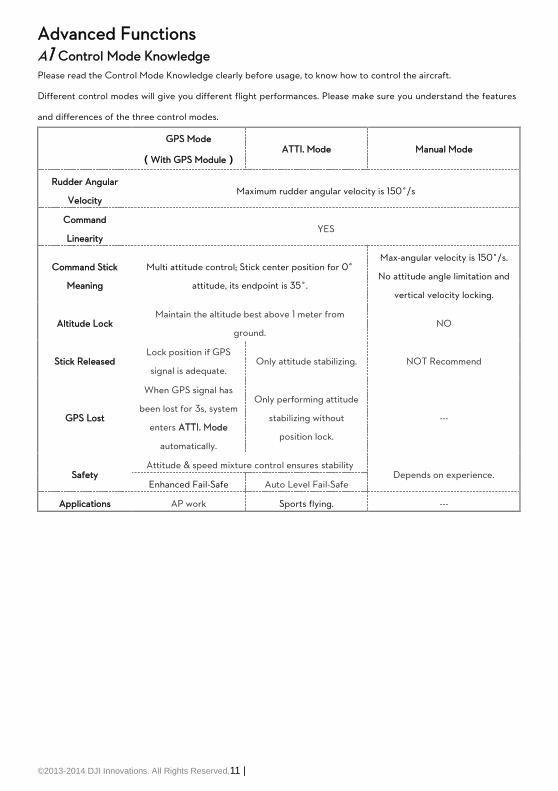
Advanced Functions A1 Control Mode Knowledge
Please read the Control Mode Knowledge clearly before usage, to know how to control the aircraft.
Different control modes will give you different flight performances. Please make sure you understand the features
and differences of the three control modes.
GPS Mode
(With GPS Module) ATTI. Mode Manual Mode
Rudder Angular
Velocity Maximum rudder angular velocity is 150°/s
Command
Linearity YES
Command Stick
Meaning
Multi attitude control; Stick center position for 0˚
attitude, its endpoint is 35˚.
Max-angular velocity is 150°/s.
No attitude angle limitation and
vertical velocity locking.
Altitude Lock Maintain the altitude best above 1 meter from
ground. NO
Stick Released Lock position if GPS
signal is adequate. Only attitude stabilizing. NOT Recommend
GPS Lost
When GPS signal has
been lost for 3s, system
enters ATTI. Mode
automatically.
Only performing attitude
stabilizing without
position lock.
---
Safety Attitude & speed mixture control ensures stability
Depends on experience. Enhanced Fail-Safe Auto Level Fail-Safe
Applications AP work Sports flying. ---

©2013-2014 DJI Innovations. All Rights Reserved.12 |
A2 Start & Stop Motor Knowledge
Both Immediately Mode and Intelligent Mode are available in the Assistant Software:
Advanced->Motor->Stop Type.
If necessary, please select the Intelligent Mode in the Assistant Software.
By using the Intelligent Mode, different control mode has different way of stopping motors.
In Manual Mode, only executing CSC can stop motors.
In ATTI. Mode or GPS Mode, any one of following four cases will stop motors:
a) You don’t push throttle stick after motors start within three seconds;
b) Executing CSC;
c) Throttle stick under 10%, and after landing 3 seconds.
d) The slope angle of multi-rotor is over 70°, and throttle stick under 10%.
For Intelligent Mode
In ATTI. / GPS Mode, it has landing judgment, which will stop motors.
Start motors in ATTI. / GPS Mode, you have to execute CSC and then push throttle stick over
10% in 3 seconds, otherwise motors will stop after 3 seconds.
During normal flight, only pull throttle stick under 10% will not stop motors in any control mode.
For safety reason, when the slope angle of multi-rotor is over 70° during the flight in ATTI. /
GPS Mode (may be caused by collision, motor and ESC error or propeller broken down), and
throttle stick is under 10%, motors will stop automatically.
For Both Intelligent Mode & Immediately Mode
If you choose the Immediately Mode, you SHOULD NOT pull throttle stick under 10% during
flight, because it will stop motors. If you do it accidentally, you should push the throttle stick over
10% in 5s to re-start motors
When transmitter commands are valid under any control modes, the motors will start or stop
immediately when you execute CSC. It has nothing to do with the current throttle stick position.
Please DO NOT executes CSC during flight without a good reason.
If you choose Intelligent, throttle stick under 10% will trigger landing judgment in any control
mode. In this judgment, pitch, roll and yaw controls are denied except throttle, but multi-rotor
will still auto level.
In any control mode, DO NOT pull throttle stick under 10% during normal flight without any
reason.
The two cut off types will only work correctly if the transmitter calibration is correct.
In failed-safe, CSC is denied by the main controller, motors will hold their state.

©2013-2014 DJI Innovations. All Rights Reserved.13 |
A3 Intelligent Orientation Control (IOC) Flight (with GPS module)
Definition of Forward Direction: Multi -rotor will fly along this direction when you push the elevator stick.
Graphic Description: Forward direction
Step1 Before You Start
Usually, the forward direction of a flying multi-rotor is the same as the nose direction. By using IOC, wherever the
nose points, the forward direction has nothing to do with nose direction. The red and blue arrows on the
transmitter are corresponding to pitch and roll operations in the following diagram.
In course lock flying, the forward direction is the same as a recorded nose direction.
All the following requirements are met: the autopilot system is in ATTI. Mode or GPS Mode.
Normal flying Course Lock Flying
In home lock flying, the forward direction is the same as the direction from home point to multi-rotor.
All the following requirements are met: 6 or more GPS satellites are found, in GPS Mode, and the aircraft is
further than 10m away from the home point.
Normal flying Home Lock Flying
In POI (POI, Point Of Interest) flying, the roll channel controls the multi rotor circular flight speed around a
fixed point, the pitch channel is used for controlling the diameter around the fixed point, the throttle is used
to control the height around the fixed point.
All the following requirements are met: 6 or more GPS satellites are found, in GPS Mode, and the aircraft is
further than 5m (and less than 500m) away from the Point of Interest.
Normal flying POI Flying
©2013-2014 DJI Innovations. All Rights Reserved.14 |
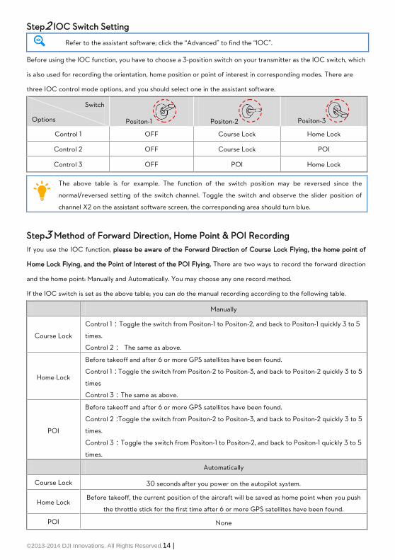
Step2 IOC Switch Setting
Refer to the assistant software; click the “Advanced” to find the “IOC”.
Before using the IOC function, you have to choose a 3-position switch on your transmitter as the IOC switch, which
is also used for recording the orientation, home position or point of interest in corresponding modes. There are
three IOC control mode options, and you should select one in the assistant software.
Switch
Options Positon-1 Positon-2 Positon-3
Control 1 OFF Course Lock Home Lock
Control 2 OFF Course Lock POI
Control 3 OFF POI Home Lock
The above table is for example. The function of the switch position may be reversed since the
normal/reversed setting of the switch channel. Toggle the switch and observe the slider position of
channel X2 on the assistant software screen, the corresponding area should turn blue.
Step3 Method of Forward Direction, Home Point & POI Recording
If you use the IOC function, please be aware of the Forward Direction of Course Lock Flying, the home point of
Home Lock Flying, and the Point of Interest of the POI Flying. There are two ways to record the forward direction
and the home point: Manually and Automatically. You may choose any one record method.
If the IOC switch is set as the above table; you can do the manual recording according to the following table.
Manually
Course Lock
Control 1:Toggle the switch from Positon-1 to Positon-2, and back to Positon-1 quickly 3 to 5
times.
Control 2: The same as above.
Home Lock
Before takeoff and after 6 or more GPS satellites have been found.
Control 1:Toggle the switch from Positon-2 to Positon-3, and back to Positon-2 quickly 3 to 5
times
Control 3:The same as above.
POI
Before takeoff and after 6 or more GPS satellites have been found.
Control 2:Toggle the switch from Positon-2 to Positon-3, and back to Positon-2 quickly 3 to 5
times.
Control 3:Toggle the switch from Positon-1 to Positon-2, and back to Positon-1 quickly 3 to 5
times.
Automatically
Course Lock 30 seconds after you power on the autopilot system.
Home Lock Before takeoff, the current position of the aircraft will be saved as home point when you push
the throttle stick for the first time after 6 or more GPS satellites have been found.
POI None

©2013-2014 DJI Innovations. All Rights Reserved.15 |
LED will blink GREEN quickly if Forward Direction recording is successful.
LED will blink PURPLE quickly if Home Point recording is successful.
LED will blink CYAN quickly if POI recording is successful.
After Home Point is recorded successfully, LED will blink continually under
below conditions. None of these conditions is omitted.
1. GPS signal is well, the satellites number MC searched is more than 6.
2. Distance between aircraft and the recorded home point is less than 8m.
3. Current control mode is not Manual mode.
DO NOT toggle the switch between Positon-1 to Positon-3, since it may change the recording
of the Positon-2.
Step4 IOC Flying Test
Then you can do Course Lock, Home Lock, and POI flying test
Carry out an IOC flight by the following procedure. The Control Mode LED will blink GREEN to indicate the IOC
mode only when the main controller is really to fly in Course Lock, Home Lock modes or POI.
During the
same flight STEP1: Record STEP2: ON STEP3: OFF STEP4: ON again
Course
Lock
Switch
Setting
Record the
forward
direction
Set Control Mode switch at
GPS or ATTI. position,
Toggle IOC switch from OFF
to Course Lock position
Toggle IOC
switch to OFF
position
Toggle IOC switch
from OFF to Course
Lock position
Home Lock
Switch
Setting
Record the
home point
Set Control Mode switch at
GPS position,
Toggle IOC switch from OFF
to Home Lock position
Toggle IOC
switch to OFF
position
Toggle IOC switch
from OFF to Home
Lock position
POI
Switch
Setting Record the POI
Set Control Mode switch at
GPS position,
Toggle IOC switch from OFF
Toggle IOC
switch to OFF
position
Toggle IOC switch
from OFF to POI
position

©2013-2014 DJI Innovations. All Rights Reserved.16 |
to POI position
Aircraft moving direction when pull pitch stick Aircraft moving direction when pull roll stick
Home point Aircraft(the arrow is pointing to the direction of the aircraft nose)
IOC FLYING NOTES!!!
When Multi-rotor is flying by home lock far away from you and the home point, please DO NOT
toggle the IOC switch many times quickly so as to avoid the change of home point without your
attention.
Home lock flying requires that 6 or more GPS satellites are found and the aircraft is further than
10m away from the home point.
In POI flying, avoid using POI in areas where the GPS signal might be lost or the transmitter
/receiver signal might be lost (such as built up urban areas), to make sure 6 or more GPS
satellites are found. And the multi-rotor is required to fly further than 5m (and less than 500m)
away from the Point of Interest.
Continuously spinning will cause a yaw error. In this case, you can stop or slow down the
spinning, so as to have better flight performance.
If the IOC flying requirement is not satisfied, the autopilot system will quit IOC control mode.
Please be aware of the LED indicator, to know the current control mode of the autopilot system.
Before you do the home lock flight, you have to fly the aircraft out of the 10m range around
home point, and then flip the IOC switch to Home Lock position to fly in home lock when all the
requirements are met. If you have already toggled the IOC switch to Home Lock position when
the aircraft is still in 10m range around home point, and this is the first time you are going to fly
in home lock during the current flight, then if all the requirements are met, the main controller
will change into home lock automatically when Multi-rotor flies out the 10m range around home
point..
When you are flying in home lock mode, if the aircraft is back into the 10m range around home
point, or you switch into ATTI. Mode, or the GPS signal becomes weak, the autopilot system will
fly in course lock by the current forward direction automatically. But this forward direction is
NOT the recorded forward direction. If you open the course lock now, it will fly in course lock
still by the earlier recorded forward direction.
We suggest that you should know clearly that, by which lock method you are going to fly, and
the locked forward direction or home point, before you switch on IOC mode during the flight.
Refer to the LED Description in the Appendix for more details.

©2013-2014 DJI Innovations. All Rights Reserved.17 |
A4 FailSafe
FailSafe methods include Hover, Go-home, and Altitude Go-home. Choose one as your failsafe method, which will
be triggered when the MC loses the control signal in one of the following situations:
1) Signal lost between transmitter and receiver, e.g. multi-rotor is out of the communication range, or
transmitter has failed, etc.
2) One or more connections of A, E, T, R, U channels between the MC and receiver is lost. If this happens
before take-off, the motors will not start if you raise the throttle stick. If this happens during the flight, the
LED will flash blue to warn you, in addition to the fail-safe method. If Hovering fail-safe method is configured
and U channel is disconnected, multi-rotor will auto land.
Also, you can select the Go-Home Switch item to start go-home (Go-home, and Altitude Go-home) by using a TX
switch during the flight, when selected during flight the LED will flash purple instead of blue.
The multi-rotor position before takeoff, including reference longitude, reference latitude and reference altitude, is
saved as home point by the MC automatically when you raise the throttle stick for the first time AND it has 6 or
more GPS satellites acquired for more than 8 seconds ( blinks once or no blinking >8secs)
After taking off, every time the aircraft recorded a home-point successfully the LED will blink Cyan quickly for
indicating.
THEREFORE: to use any form of Go-home (including failsafe return home), you must make sure 6 or more GPS
satellites are acquired for more than 8 seconds ( blinks once or no blinking >8secs) before take-off, this will
assure correct recording of the Home position.
Go-Home Altitude: Determined by the reference altitude and the FailSafe method chosen. That is, the go-home
altitude may be different due to fail-safe method chosen.
Hover
The aircraft will remain hovering when the fail-safe starts.
1 Record 2 Flight
Tx
3 Hover
Tx
Aircraft Fail-safe
Home Location
(Reference longitude, latitude, altitude )
Signal lost
Stay hoverIf GPS satellite found >= 6 and last 8s,
at the first time you pull the throttle
stick, then record Home Location
Go-H (Go-home)

©2013-2014 DJI Innovations. All Rights Reserved.18 |
Flight altitude when fail-safe starts > (reference altitude+20m),then go-home altitude=flight altitude when
fail-safe starts
Flight altitude when fail-safe starts <= (reference altitude+20m),then go-home altitude=reference altitude +20m
1 Record 2 Flight
Tx
3 Hover
Tx
5 Go home
Tx Tx
4 Ready to go home
Tx
6 Land
20m
Home Go homeAircraft Fail-safe/Enable Go-Home Switch
Home Location
(Reference longitude, latitude, altitude )
Signal lost
Stay hover
Signal lost > 3s
Ready to
Go-Home Hover 15s ,
Then land.
If GPS satellite found >= 6 and last 8s,
at the first time you pull the throttle
stick, then record Home Location
Flight altitude when fail-safe starts
>(reference altitude+20m)
Flight altitude when fail-safe starts
<=(reference altitude+20m)
Altitude Go-H (Altitude Go-home)
Flight altitude when fail-safe starts > (reference altitude + entered value),then go-home altitude=flight altitude
when fail-safe starts.
Flight altitude when fail-safe starts <= (reference altitude + entered value),then go-home altitude=
reference altitude + entered value.
Entered value: 20m~300m, the default value is 20m, and has an accuracy of 1m.
2 Flight
Tx
3 Hover
Tx
5 Go home
Tx Tx
4 Ready to go home
Tx
6 Land
Input value
1 Record
Home Go home Input valueAircraft Fail-safe/Enable Go-Home Switch
If GPS satellite found >= 6 and last 8s,
at the first time you pull the throttle
stick, then record Home Location
Home Location
(Reference longitude, latitude, altitude )
Signal lost
Stay hover
Signal lost > 3s
Ready to
Go-Home Hover 15s ,
Then land.
Flight altitude when fail-safe starts>(reference altitude+ input value)
Flight altitude when fail-safe starts<=(reference altitude+ input value)
Go-Home Switch: Before using this function, you have to choose a
2-position switch on your transmitter as the Go-Home switch. Then connect
the correct channel of the receiver to the X3 port of the MC.
You should assign: Position-1 to Start; Position-2 to Standby; or reverse the assignment for Position-1 and Position-2.
Move the Tx switch of the channel X3 and check that the corresponding area Start and Standby turns blue on the
assistant software screen. If required adjust the Tx channel end points.
1 22-Position
Tx

©2013-2014 DJI Innovations. All Rights Reserved.19 |
Switching from Standby to Start will enable go-home during flight and you will no longer have
flight control of the Multi rotor. If the multi-rotor is already in a failsafe condition, then the
go-home switch will not work.
If you switch to Manual Mode or Atti. Mode, (and the multi rotor is not in a fail-safe condition),
then the go-home is cancelled and you regain control of the multi copter. Once GPS. Mode is
re-selected you can once again use the go-home function.
Use end-point fine tuning on your transmitter to adjust the X3 channel, to give the correct
switch indication in the assistant software.
The following example shows how to enable Go-home by the Tx Switch. Use position-1 to Start
and Position-2 to Standby for example.
Position -1 Position -2 Position -1, if the initial switch position is at Start (Position -1).
Position -2 Position -1, if the initial switch position is at Standby (Position -2).
The home point of the ground station one key go-home is the same as the point set by user in
the ground station software.
If the home point is not set by the ground station, the home point of the ground station one
key go-home function is the point recorded by the MC.
If the Go-Home Switch cannot be selected in the assistant software, that may be due to the X3
channel been set for remote gain tuning, you should change this if required.
©2013-2014 DJI Innovations. All Rights Reserved.20 |
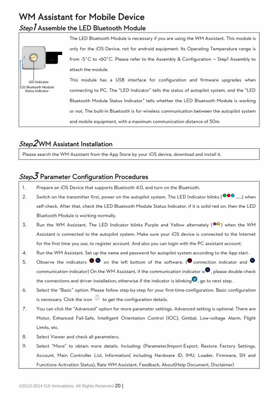
WM Assistant for Mobile Device Step1 Assemble the LED Bluetooth Module
ANT
LED Indicator
LED Bluetooth Module Status Indicator
The LED Bluetooth Module is necessary if you are using the WM Assistant. This module is
only for the iOS Device, not for android equipment. Its Operating Temperature range is
from -5°C to +60°C. Please refer to the Assembly & Configuration -> Step1 Assembly to
attach the module.
This module has a USB interface for configuration and firmware upgrades when
connecting to PC. The “LED Indicator” tells the status of autopilot system, and the “LED
Bluetooth Module Status Indicator” tells whether the LED Bluetooth Module is working
or not. The built-in Bluetooth is for wireless communication between the autopilot system
and mobile equipment, with a maximum communication distance of 50m.
Step2 WM Assistant Installation
Please search the WM Assistant from the App Store by your iOS device, download and install it.
Step3 Parameter Configuration Procedures
1. Prepare an iOS Device that supports Bluetooth 4.0, and turn on the Bluetooth.
2. Switch on the transmitter first, power on the autopilot system. The LED Indicator blinks ( ……) when
self-check. After that, check the LED Bluetooth Module Status Indicator, if it is solid red on, then the LED
Bluetooth Module is working normally.
3. Run the WM Assistant. The LED Indicator blinks Purple and Yellow alternately ( ) when the WM
Assistant is connected to the autopilot system. Make sure your iOS device is connected to the Internet
for the first time you use, to register account. And also you can login with the PC assistant account.
4. Run the WM Assistant. Set up the name and password for autopilot system according to the App start.
5. Observe the indicators on the left bottom of the software. ( connection indicator and
communication indicator) On the WM Assistant, if the communication indicator is , please double check
the connections and driver installation; otherwise if the indicator is blinking , go to next step.
6. Select the “Basic” option. Please follow step-by-step for your first-time-configuration. Basic configuration
is necessary. Click the icon to get the configuration details.
7. You can click the “Advanced” option for more parameter settings. Advanced setting is optional. There are
Motor, Enhanced Fail-Safe, Intelligent Orientation Control (IOC), Gimbal, Low-voltage Alarm, Flight
Limits, etc.
8. Select Viewer and check all parameters.
9. Select “More” to obtain more details. Including: (Parameter)Import-Export, Restore Factory Settings,
Account, Main Controller List, Information( including Hardware ID, IMU, Loader, Firmware, SN and
Functions Activation Status), Rate WM Assistant, Feedback, About(Help Document, Disclaimer)

©2013-2014 DJI Innovations. All Rights Reserved.21 |
If the LED Bluetooth Module Status Indicator does not be solid red on, then the LED Bluetooth
Module works abnormally. There are following situations:
(1) The main controller firmware version is not matched, please upgrade the main controller.
(2) There is something wrong with the connection between the LED Bluetooth module and main
controller, please check the connection.
(3) The LED Bluetooth module is damaged, please contact your dealer.
iOS Device List
iPhone 4s, iPhone 5, iPod touch 5, iPad mini, iPad 3, iPad 4
Refer to the WM Assistant for more details.
The gain value displayed on Mobile Device and PC may be a little different, that is OK for use.
Step4 Flying Test Procedures
1. Get the aircraft ready, run the WM Assistant and make sure it is connected with the main controller. (The
indicators on the WM Assistant are )
2. Start the motors.
3. The “View” page shows the relative parameters real-time when flying.
4. Go to the “Basic” and click into the “Gain” page to set the values of all gains real-time during flying.
5. Go to the “Advanced” and click into the “Gimbal” page to configure the gimbal real-time during flying.
6. Finish the flying and land your aircraft.
Only the parameter referred above can be changed during flying. Others can be configured after
landing.
Forgot Main Controller Password
When connecting to the WooKong M flight control system to the WM Assistant using a mobile device for the first
time, users will be asked to set a name and password for the WooKong M main controller. If the password is
forgotten, users can connect the flight control system to Assistant software on a PC and click “Reset Bluetooth
Info” in the Tools page to reset username and password. Once complete, set a new username and password as
before.
How to Activate More Functions
In the Future you might be asked to fill in the new S/N in the future if you brought new function upgrades. Fill-in
the S/N and then click Write button. If you filled in an invalid S/N over 30 times, your MC will be locked and you
have to contact our customer support.

©2013-2014 DJI Innovations. All Rights Reserved.22 |
Appendix Firmware & Assistant Software Upgrade
Please follow the procedure for software and firmware upgrade; otherwise the autopilot system might not work
properly. For SAFETY REASONS, DO NOT use power battery during firmware upgrade.
1. Make sure your computer is connected to the Internet.
2. Please close all the other applications during the firmware upgrade, including anti-virus software and
firewall.
3. Make sure the power supply is securely connected. DO NOT un-plug the power supply until firmware
upgrade has finished.
4. Connect autopilot system to PC with USB cable, DO NOT break connection until firmware upgrade is
finished.
5. Run Software and wait for connection.
6. Select InfoSoftware and Firmware.
7. DJI server will check your current software and firmware version, and get the latest software and
firmware prepared for the unit.
8. If there is a software version more up-to-date than your current version, you will be able to click to
download the new version. Please re-install the assistant software follow the prompts
9. If there is a firmware version more up-to-date than your current version, you will be able to click to
update them.
10. Wait until Assistant software shows “finished”.
11. Click OK and power cycle the unit after at least 5 seconds. Your unit is now up-to-date.
After firmware upgrade, please re-configure the system using Assistant software. If the firmware upgrade failed, the autopilot system will enter waiting for firmware upgrade
status automatically, please try again with the above procedures.

©2013-2014 DJI Innovations. All Rights Reserved.23 |
Port Description
Please remember the function of each port, which may help you to use the autopilot system efficiently.
Main Controller
A For roll control (left/right)
E For pitch control (front/back)
T For throttle control Or to gimbal roll servo
R For rudder control Or to gimbal pitch servo
U For Control Mode Switch
X1 For voltage monitor (Connect with PMU V-SEN port)
X2 For D-Bus (S-Bus/S-Bus2 compatible) Or for gain tuning Or for IOC switch
X3 For gimbal pitch control Or for gain tuning Or for switch go-home
M6
To #6 rotor
M5
To #5 rotor
M4
To #4 rotor
M3
To #3 rotor
M2
To #2 rotor
M1
To #1 rotor
F2
To gimbal pitch servo Or to #8 rotor
F1
To gimbal roll servo Or to #7 rotor
Micro-B USB port: PC connection for configuration and firmware upgrades.
CAN-Bus port: MC uses CAN-Bus to power and communicate with other WKM modules.
(In three-pin ports, pins near the nicks are signal pins.)
Power Management Unit
V-SEN For monitoring battery voltage and supplying power to receiver and other electronic devices.
(Connect with MC X1 port)
Orange wire (signal wire) output: 0V ~ + 3.3V
Red wire (power wire) output: 3A@5V
PW For supplying power to WKM system.
Output: Max 2A@6V

©2013-2014 DJI Innovations. All Rights Reserved.24 |
LED Description
Flight States
Manual Mode Atti. Mode GPS Mode IOC Tx Signal Lost
GPS satellites < 5
GPS satellites= 5
GPS satellites =6
Attitude & GPS good
Attitude status fair
Attitude status bad
IMU data Lost
Aircraft off home point
less than 8m ---
Flashing indications of , , are: Single flash, all the transmitter sticks are at center position, multi rotor
hovering; Double flash, transmitter stick(s) not at center position, speed command is not zero.
Compass Calibration and Abnormal Data Indicator
Begin horizontal calibration
Begin vertical calibration
Calibration finished
Calibration Failure or others error
Abnormal Compass Data
Low Voltage Warning
First level protection
Second level protection
Recording
Record a home-point successfully
Record a forward direction successfully
Record a Point Of Interest successfully
WM Assistant Connection Indicator
WM Assistant is connected to the autopilot system
Main Controller LED
MC is functioning correctly.
Boot loader mode, MC is waiting for firmware upgrade.
Firmware upgrade has finished. MC is waiting for reboot.
Error occurred during firmware upgrade, MC reboot is required. or
PMU LED
PMU connection is correct.
Connection between PMU and battery is wrong (polarity error).

©2013 DJI Innovations. All Rights Reserved.25 |
Specifications
General
Built-In Functions Three Modes Autopilot
PPM Receiver Supported
2-axle Gimbal Support
Enhanced Fail Safe
S-Bus/S-Bus2 Receiver Supported
Intelligent Orientation Control
Multi Output Frequency Supported
Low Voltage Protection
Peripheral
Supported Multi-rotor Quad-rotor: I4, X4;
Hexa-rotor: I6, V6, Y6, IY6;
Octo-rotor: X8, I8, V8.
Supported ESC output 400Hz refresh frequency.
Recommended Transmitter Only PCM or 2.4GHz with minimum 7 channels and
fail-safe function available on all channels.
Recommended Battery 2S ~ 6S LiPo
Assistant Software System Requirement Windows XP SP3 / 7 /8
Electrical & Mechanical
Power Consumption MAX 5W
(0.9A@5V, [email protected], [email protected], 0.4A@8V)
Operating Temperature -5°C to +60°C
Total Weight <= 118g (overall)
Dimensions MC: 51.2mm x 38.0mm x 15.3mm
IMU: 41.4mm x 31.1mm x 27.8mm
GPS & Compass: 50mm (diameter) x 9mm
LED Indicator: 25mm x 25mm x 7mm
PMU: 39.5mm×27.5mm×9.7mm
Flight Performance (can be effected by mechanical performance and payloads)
Hovering Accuracy (GPS Mode) Vertical: ± 0.5m
Horizontal: ± 2m
Maximum Wind Resistance <8m/s (17.9mph / 28.8km/h)
Max Yaw Angular Velocity 150deg/s
Max Tilt Angle 35°
Ascent / Descent ±6m/s

©2013-2014 DJI Innovations. All Rights Reserved.26 |
FAQ Fix the TBE (Toilet Bowl Effect) Problem
When flying in GPS Mode and the compass calibration has been done correctly, should you find the aircraft
rotating (Toilet bowl effect), or drifting when hovering. Please check the GPS module mounting orientation and
then re-do the compass calibration. Carry out the following procedure to re-mount the GPS module.
In the following diagram (view from the top), the aircraft can appear to be rotating in both clockwise and
counter-clockwise direction, please re-mount the GPS module correspondingly.
is the rotating direction of aircraft, is the nose direction of aircraft,
is the arrow direction on the GPS module, θ is the offset angle for GPS re-mounting(about 10~30o)
Clockwise rotating GPS re-mounting Counter Clockwise
rotating
GPS re-mounting
θ
θ
Reinstall the GPS in an Offsetting Angle
Should you find the
multi-rotor does not track
straight in forward flight,
you might try
re-mounting GPS in an
offsetting angle as
showed in right figure. Θ
in the figure is the
offsetting angle.
Attitude Controllable When One Motor Output is Failed
For Hexa-rotor, including Hexa-rotor I, Hexa-rotor V, Hexa-rotor IY and Hexa-rotor Y, aircraft is attitude
controllable when one motor output is failed.
The WKM can still control the attitude of the Hexa-rotor for a safe landing when one motor output of the
Hexa-rotor has failed, for example, one motor is stopped or one propeller is broken, etc.
The control mode of WKM should be in Atti. Mode or GPS Mode. The aircraft will rotate, due to an imbalance of
torque; however, it can still be controlled by the Transmitter.
Objective flight direction
GPS mounting direction
GPS mounting direction
Actual flight direction
Objective flight direction
Actual flight direction
1 2 3
θ
θ
Without GPS offset angle
With GPS offset angle

©2013-2014 DJI Innovations. All Rights Reserved.27 |
Select Course lock or home lock mode for flying the aircraft into a safe area to land when the aircraft is far away or
the attitude can’t be recognized. Even when the multi rotor is rotating, using Course lock or home lock mode will
allow you to move the multi rotor in the corresponding Transmitter stick direction.
Flight Restriction in Specified Area Description
Flight Functions are restricted within the radius of 15Km from Tiananmen Square in Beijing, China.
In the restricted area, with GPS/Compass Module and GPS signal is good, you cannot take off the aircraft in any
Control Mode.
In the restricted area, with GPS/Compass Module and GPS signal is bad, you can take off the aircraft, once the
GPS signal becomes good, you can only control the aircraft to land. Manual Mode is free form restriction.
Fly into the restricted area, you can only control the aircraft to land. Manual Mode is free form restriction.
Abnormal Cases in Motor Test
Below are abnormal cases and solutions for Motor Test in the Assistant software
(1) Tested motor does not rotate, there are two situations:
a) Connection issues: please check the connections first, such as whether MC and motors are power on,
whether connection between MC and ESC is well, whether three cables of ESC are correctly
connected to motor. If connections are well, then check whether motors or ESC are breakdown.
b) Please increase the Motor Idle Speed in the Advanced page of Assistant software.
(2) Tested motor rotates in wrong direction: please swap over any two wire connections of the motor.
(3) Rotating motor is not the tested motor (e.g. M2 motor rotates when click button”M1”): please ensure the
cable of ESC is correct connected to the right port of MC.
Solution for LED yellow and green blinking
LED blinks yellow and green ( ) alternatively means compass errors or interferences:
(1) Long time : in this case compass calibration is required.
(2) Temporary : e.g. LED blinks several times when the aircraft flying over some district and then no
blinks; or take an calibrated aircraft from outside to inside of house, the may appear inside. In these cases the
compass is ok and has no influences to flight. Compass calibration is not required.
When compass data become abnormal (LED blinks yellow and green ) during flying, for safety reasons, the
autopilot system will auto change the control mode. However in ATTI. and Manual Mode is free from influence. In
any other control mode, the autopilot system will enter into ATTI. Mode automatically (the mode shown on status
bar will be “Atti.” if you connect the autopilot to the assistant software). Once the compass data go back to normal,
the autopilot system will regain the original control mode.

©2013-2014 DJI Innovations. All Rights Reserved.28 |
Solutions for failed gain value adjustment in the Assistant software
If you fail to adjust the gain value in the Assistant software, please check the follow items to solve the problem.
(1) Make sure the MC has connected and communicated with the Assistant software successfully.
(2)Make sure the Receiver has connected to the MC successfully.
(3)Make sure you have selected the correct Receiver type in the Assistant software, and then you can try to adjust
the gain value again.

©2013-2014 DJI Innovations. All Rights Reserved.29 |
CE Statement Due to the used enclosure material, the devices shall only be connected to a USB.
Interface of version 2.0 or higher. The connection to so called power USB is prohibited.
Hereby, SZ DJI TECHNOLOGY CO. LTD declares that this device is in compliance with the essential requirements
and other relevant provisions of Directive 1999/5/EC.
FCC Statement:
This equipment complies with FCC RF radiation exposure limits set forth for an uncontrolled environment.
This device complies with part 15 of the FCC rules. Operation is subject to the following two conditions: (1) this
device may not cause harmful interference, and (2) this device must accept any interference received, including
interference that may cause undesired operation.
NOTE: The manufacturer is not responsible for any radio or TV interference caused by unauthorized modifications
or changes to this equipment. Such modifications or changes could void the user’s authority to operate the
equipment.
NOTE: This equipment has been tested and found to comply with the limits for a Class B digital device, pursuant to
part 15 of the FCC Rules. These limits are designed to provide reasonable protection against harmful
interference in a residential installation. This equipment generates uses and can radiate radio frequency energy
and, if not installed and used in accordance with the instructions, may cause harmful interference to radio
communications. However, there is no guarantee that interference will not occur in a particular installation. If
this equipment does cause harmful interference to radio or television reception, which can be determined by
turning the equipment off and on, the user is encouraged to try to correct the interference by one or more of the
following measures:
- Reorient or relocate the receiving antenna.
- Increase the separation between the equipment and receiver.
-Connect the equipment into an outlet on a circuit different from that to which the receiver is connected.
-Consult the dealer or an experienced radio/TV technician for help.