Embed Size (px)
Citation preview
Mechanical Engineering Department
WORCESTER POLYTECHNIC INSTITUTE MECHANICAL ENGINEERING DEPARTMENT
STRESS ANALYSIS ES-2502, C’2012
Lecture 12:
02 February 2012

Mechanical Engineering Department
Instructor: Cosme Furlong HL-151
(508) 831-5126 [email protected]
http://www.wpi.edu/~cfurlong/es2502.html
General information
Teaching Assistants: Morteza Khaleghi HL-150
(508) 831-5125 [email protected]
Tatiana Popova
Mechanical Engineering Department
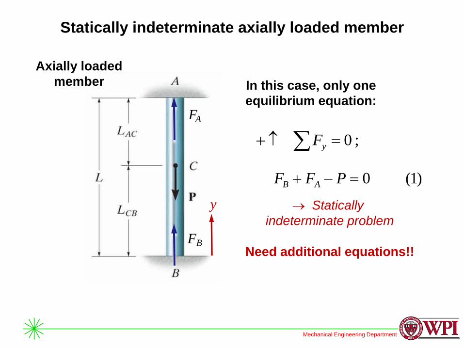
Statically indeterminate axially loaded member
Axially loaded
member
y Statically
indeterminate problem
Need additional equations!!
In this case, only one
equilibrium equation:
;0 yF
)1(0 PFF AB
FA
FB

Mechanical Engineering Department
Statically indeterminate axially loaded member
Axially loaded
member
y
Additional equations are
obtained by applying:
Compatibility or
kinematic equations
Load-displacement
equations
0/ BA
Mechanical Engineering Department
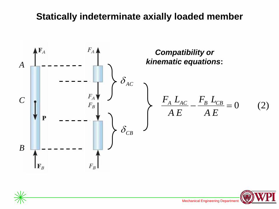
Statically indeterminate axially loaded member
Compatibility or
kinematic equations:
C
A
B
AC
CB
)2(0EA
LF
EA
LF CBBACA
Mechanical Engineering Department
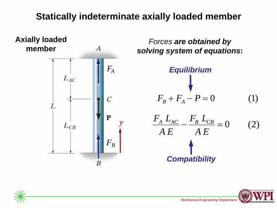
Statically indeterminate axially loaded member
Axially loaded
member
y
FA
FB
Forces are obtained by
solving system of equations:
)2(0EA
LF
EA
LF CBBACA
Compatibility
)1(0 PFF AB
Equilibrium

Mechanical Engineering Department
Axial load: example F
The 304 stainless steel post A has a diameter of d = 2 in and is
surrounded by a red brass C83400 tube B. Both rest on the rigid
surface. If a force of 5 kip is applied to the rigid cap, determine the
average normal stresses developed in the post and the tube.
Approach:
1) Apply equilibrium
equations
2) Apply compatibility
equations
3) Solve for stresses
Mechanical Engineering Department
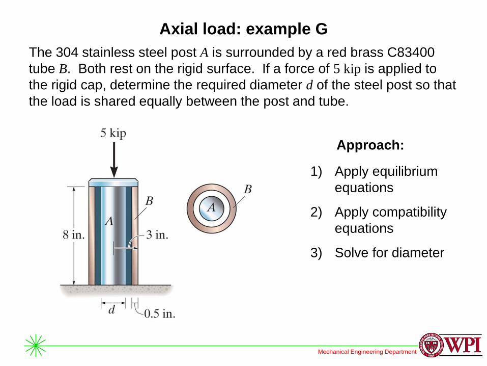
Axial load: example G
Approach:
1) Apply equilibrium
equations
2) Apply compatibility
equations
3) Solve for diameter
The 304 stainless steel post A is surrounded by a red brass C83400
tube B. Both rest on the rigid surface. If a force of 5 kip is applied to
the rigid cap, determine the required diameter d of the steel post so that
the load is shared equally between the post and tube.
Mechanical Engineering Department
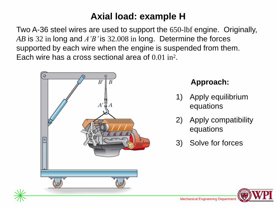
Axial load: example H
Two A-36 steel wires are used to support the 650-lbf engine. Originally,
AB is 32 in long and A’B’ is 32.008 in long. Determine the forces
supported by each wire when the engine is suspended from them.
Each wire has a cross sectional area of 0.01 in2.
Approach:
1) Apply equilibrium
equations
2) Apply compatibility
equations
3) Solve for forces
Mechanical Engineering Department
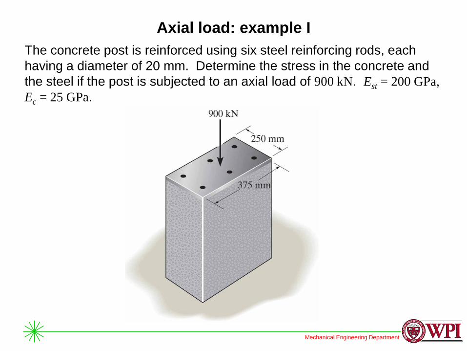
Axial load: example I
The concrete post is reinforced using six steel reinforcing rods, each
having a diameter of 20 mm. Determine the stress in the concrete and
the steel if the post is subjected to an axial load of 900 kN. Est = 200 GPa,
Ec = 25 GPa.
Mechanical Engineering Department
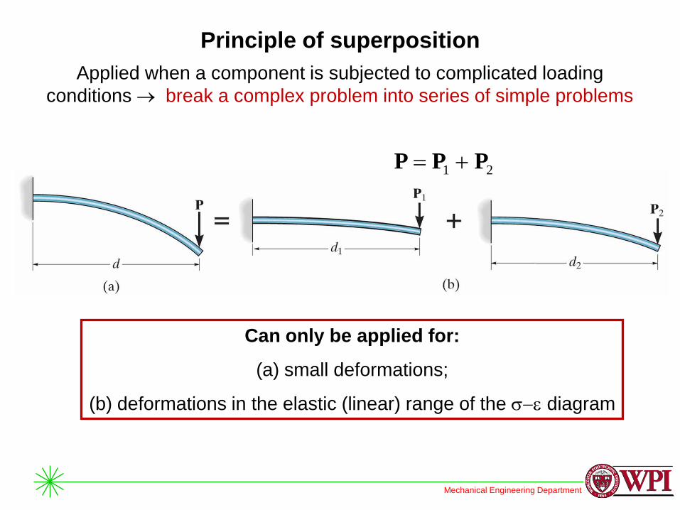
Principle of superposition
Applied when a component is subjected to complicated loading
conditions break a complex problem into series of simple problems
21 PPP
Can only be applied for:
(a) small deformations;
(b) deformations in the elastic (linear) range of the diagram
Mechanical Engineering Department
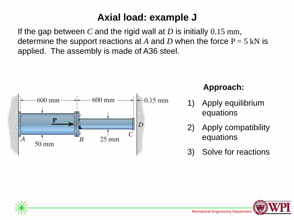
Axial load: example J
If the gap between C and the rigid wall at D is initially 0.15 mm,
determine the support reactions at A and D when the force P = 5 kN is
applied. The assembly is made of A36 steel.
Approach:
1) Apply equilibrium
equations
2) Apply compatibility
equations
3) Solve for reactions
Mechanical Engineering Department
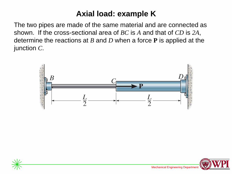
Axial load: example K
The two pipes are made of the same material and are connected as
shown. If the cross-sectional area of BC is A and that of CD is 2A,
determine the reactions at B and D when a force P is applied at the
junction C.
Mechanical Engineering Department
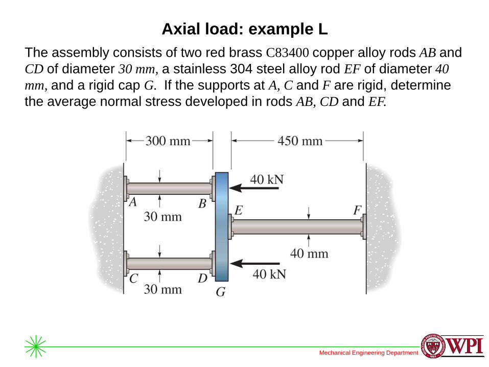
Axial load: example L
The assembly consists of two red brass C83400 copper alloy rods AB and
CD of diameter 30 mm, a stainless 304 steel alloy rod EF of diameter 40
mm, and a rigid cap G. If the supports at A, C and F are rigid, determine
the average normal stress developed in rods AB, CD and EF.
Mechanical Engineering Department
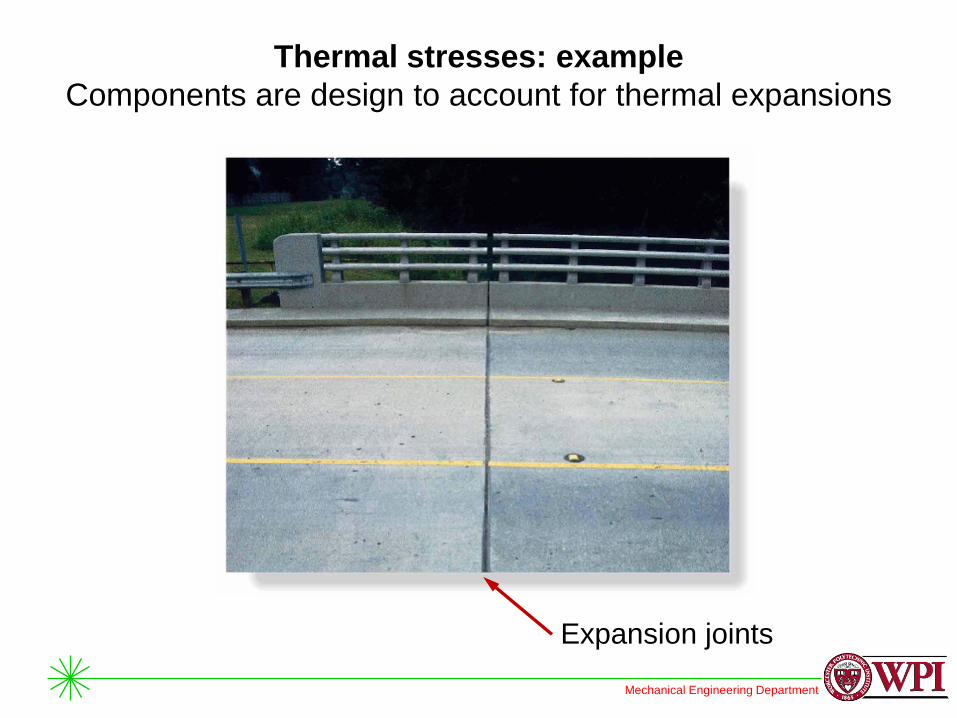
Thermal stresses: example
Components are design to account for thermal expansions
Expansion joints
Mechanical Engineering Department
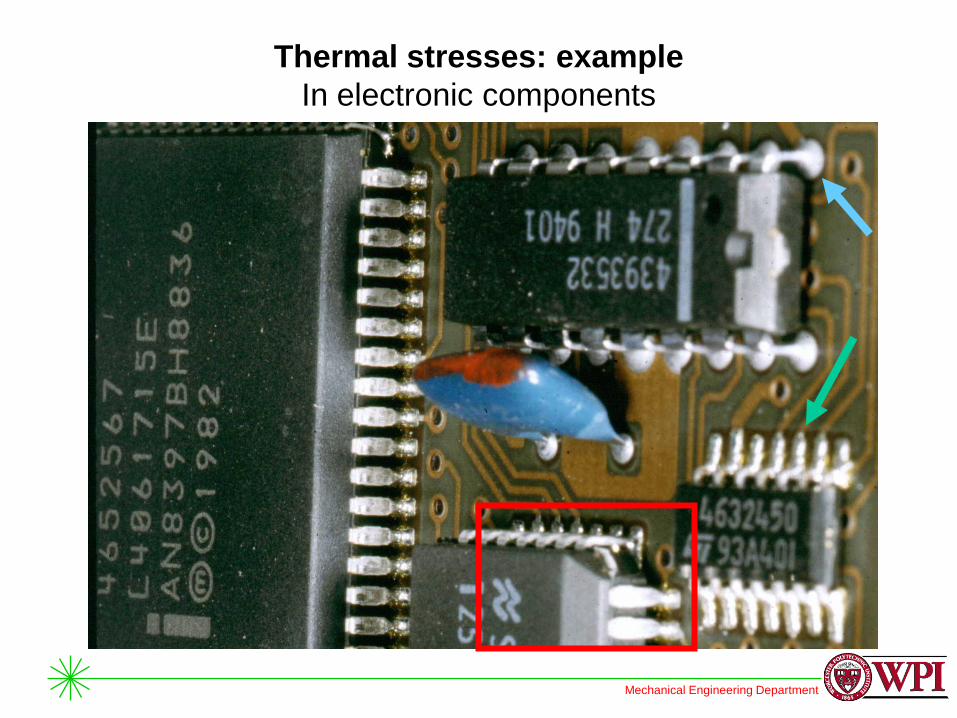
Thermal stresses: example
In electronic components

Mechanical Engineering Department
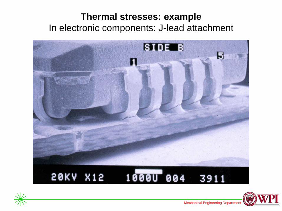
Thermal stresses: example
In electronic components: J-lead attachment

Mechanical Engineering Department
Thermal stresses: example
In electronic components: J-lead attachment
Mechanical Engineering Department
Thermal stresses: example
In electronic components: J-lead attachment
Mechanical Engineering Department
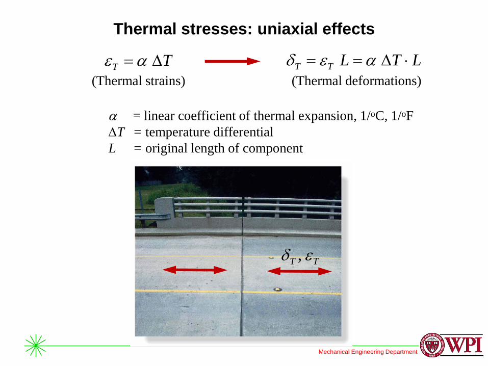
Thermal stresses: uniaxial effects
TT ,
TT (Thermal strains)
LTLTT (Thermal deformations)
= linear coefficient of thermal expansion, 1/oC, 1/oF
T = temperature differential
L = original length of component
Mechanical Engineering Department
Reading assignment
• Chapters 3 and 4 of textbook
• Review notes and text: ES2001, ES2501

Mechanical Engineering Department
Homework assignment
• As indicated on webpage of our course