Embed Size (px)
Citation preview

PHX-150Dry Ice Cleaning System
U S E R ’ S G U I D E

****************************************************TTAABBLLEE OOFF CCOONNTTEENNTTSS**************************************************
SYSTEM I.D. …………………………………………………… Page 3
EQUIPMENT WARRANTY…………………………………… Page 4
INTRODUCTION ……………………………………………… Page 5
SAFETY PRECAUTIONS AND WARNINGS……….……… Page 6, 7
KEY COMPONENT I.D. ………..………………………..…… Page 8
CONTROL PANEL/WARNING LABEL ….………………… Page 9
OPERATION INSTRUCTIONSConnecting the Air Supply ………………………..…………. Page 10Connecting the Blast Gun …………………………...……….. Page 11Loading Dry Ice ………………………………………………. Page 12Setting the Panel Controls ……………………………..…….. Page 13, 14Temporary Shutdown ………………………………….…….. Page 15Overnight / Long Term Shutdown ……………………..……. Page 16
MAINTENANCEDaily Preventive Maintenance ………….………………...….. Page 17As Needed Maintenance
Emptying the Separator……………………………………. Page 17Changing the Separator Filter Element………………...… Page 18Changing the Inline Filter Element (Trigger Line) …...…. Page 18Changing / Adding 10W Oil ……………………………..… Page 19Checking / Adjusting the Drive Chain Tension…………... Page 19, 20
Periodic MaintenanceReplacing Airlock Critical Components…………………... Page 21-23
TROUBLESHOOTING CHART ……………………….…..… Page 24, 25
DRAWINGS / PARTS LISTSTop Level Assembly ……………………………………...…... Page 26, 27Control Panel Assembly ……………………………….……. Page 28Control Shelf Assembly ……………………………….. .….. Page 29Air System Assembly …………….……………………..…… Page 30Auger Assembly ………..……………………...……..…..….. Page 31Motor Drive Assembly (Auger) …………………….………. Page 32Airlock Assembly ……………………………………….…… Page 33Vibrator Assembly ……………………………………..……. Page 34PHX Gun Assembly……………………………………....…. Page 35Flow Schematic / Tubing Chart…………………………….. Page 36, 37
RECOMMENDED SPARE PARTS …………………..…..…. Page 38
SPECIFICATIONS …………………………………….…..….. Page 39
**************************************************************************************************PPHHXX--115500********************Page 2

SYSTEM I.D.
This User’s Guide is printed for use with the following dry ice cleaning system:
Model: PHX-150
Part Number: 30000-001F
Serial Number:
Manufacturing Date:
U.S. Patent No. 6,346,035
It is recommended that the above information be kept in a safe place. Have it readilyavailable when utilizing the services of the manufacturer with regards to technicalsupport, service, parts, etc.
The written material herein contains proprietary information intended for the sole use ofthe original owner. It may not be duplicated or disclosed to other parties.
Inspected By: __________________________ Date: __________________________
©2010 Phoenix Unlimited LLC. All rights reserved.Federal law provides severe civil and criminal penalties for the unauthorized
reproduction or distribution of copyrighted material.
**************************************************************************************************PPHHXX--115500********************Page 3

Phoenix Unlimited LLC Equipment Warranty
Phoenix Unlimited LLC (the Company) warrants that the Equipment it manufactures anddelivers hereunder will be free of defects in material and workmanship for a period oftwelve months or 2000 hours of operation from the date of shipment, whichever occurs first.Upon written request, Phoenix Unlimited shall, at its option, correct any nonconformity bysuitable repair to such Equipment, or furnish a replacement part F.O.B. point of shipment,provided the Purchaser has stored, installed, maintained and operated such Equipment inaccordance with good industry practices and has complied with specific recommendationsof the Company. The Company shall not be liable for any repairs, replacements, oradjustments to the Equipment or any costs of labor performed by the Purchaser or otherswithout the Company's prior written approval. The effects of corrosion, erosion and normalwear and tear, are specifically excluded from warranty.
Correction by the Company of nonconformities whether patent or latent, in the manner andfor the period of time provided above, shall constitute fulfillment of all liabilities of theCompany for such nonconformities, whether based on contract, warranty, negligence,indemnity, or strict liability with respect to or arising out of such Equipment.
The Purchaser shall not operate Equipment which is considered to be defective without firstnotifying the Company in writing of its intention to do so. Any such use of Equipment willbe at the Purchaser's sole risk and liability and will void warranty coverage.
Accessories or equipment furnished by the Company, but manufactured by others, shallcarry whatever warranty the manufacturers have conveyed to the Company and which canbe passed on to the Purchaser.
The Company makes no other warranty or representation of any kind whatsoever,expressed or implied, except that of title, and all implied warranties of merchantabilityand fitness for a particular purpose are hereby disclaimed.
**************************************************************************************************PPHHXX--115500********************Page 4

INTRODUCTION
Congratulations on choosing the new PHX-150 dry ice cleaning system for yourindustrial cleaning needs. Its’ unique design and variable logic control make it the perfectchoice for a wide range of applications, and in any type of environment. Using rice-sizeddry ice pellets, this versatile blasting machine not only handles your tough cleaning jobs;it cuts your overhead costs in the process. Smart design, powerful, and portability too…an industrial piece of equipment that will last for many years to come!
You are now ready to learn how to use your new PHX-150.
Before you attempt to operate the equipment, we recommend that you take the time tofully familiarize yourself with the contents of this User’s Guide. The informationcontained in this guide can save invaluable time by helping you gain a clearunderstanding of the installation, safety, operation, and maintenance procedures.
Note: Pay particular attention to the sections on “Safety Precautions and Warnings”,outlined on the following two pages.
Once you are comfortable with the information provided, you will be ready to saygoodbye to old-fashioned methods of cleaning and begin using your new dry ice blaster.With proper equipment care, you will soon see that the PHX-150 is one tool you cannotbe without.
If you have questions concerning the installation, operation, or information contained inthis User’s Guide, please contact ‘Phoenix Unlimited LLC’ at: (951) 278-2229.Customer support and technical assistance is always available.
Enjoy!
******************************************************************************************************************PPHHXX--115500********************Page 5

SAFETY PRECAUTIONS AND WARNINGS
User’s Guide InformationDry ice cleaning equipment should not be operated without proper training and theconsent of your direct supervisor or management. The information contained in theUser’s Guide will provide all the tools necessary for proper operation, safety,maintenance, and troubleshooting of the equipment. Read and understand the contents ofthis guide before using or servicing your machine.
Equipment UsageYour new cleaning system was designed for use in an industrial environment. Proper safety precautionsshould be practiced, observed, and monitored at all times. Be especially careful when blasting aroundmaterials that can shatter. Dry ice blasting adapts to many types of applications, but the high velocitypellets can cause damage to fragile items or substrates of low integrity. Remember NEVER to direct theblast stream at yourself or others.
Asphyxiation HazardSublimation of dry ice creates CO2 gas. This gas is 40% heavier than air, and thusdisplaces oxygen in low-lying areas and enclosed spaces. When blasting, always haveadequate ventilation in and around your workspace. Contaminated compressed air (ornitrogen) used as a propellant may greatly increase respiratory risk. A “High CO2”sensor/monitor with indicators is a worthwhile investment and can help preventaccidental asphyxiation.
NoiseBlasting equipment generates a high velocity air flow from the nozzle. This air flow creates friction as itpasses through normal static air, resulting in high decibel noise levels. Though these levels can becontrolled somewhat by altering pressures and flow rates, ear protection is required in all blastingsituations. Additional noise factors include the object being cleaned, distance from the targeted material,media quantity being used (ice rate), and acoustic surroundings. If you are unsure about blasting in an areaaround you or fellow co-workers, consult with your safety director for advice and/or safety parametersbefore beginning work.
Emergency Stop MechanismsYour unit is equipped with an Arm/Disarm switch located in the center of the control panel. Under normaluse, this switch acts as a convenient way to quickly interrupt power to your PHX-150. However, the truedesignated E-STOP is the full-flow valve (bright yellow with a red handle) located on the air systemmanifold under the control panel. This valve must be closed before attempting maintenance work orrepairs. A 5/16” hole is provided in the handle to accommodate your company lockout procedures, ifapplicable. Raise the locking tab to re-open the valve.
Protective GearBefore beginning work, make sure you have the proper protective gear for the job. Thisincludes the basics: Ear plugs or muffs (or both), eye protection, gloves, long sleeves,long pants, and safety shoes. Dependant upon specialized cleaning jobs, you may alsoneed other protective items such as: self-contained breathing apparatus, respirator,grounding straps, skin protectors, jumpsuit, special clothing, or other equipment asdeemed necessary by your company’s safety regulations.
**************************************************************************************************PPHHXX--115500********************Page 6

ErgonomicsThe training process for using your new PHX-150 is relatively easy, but there will still be a “learningcurve” where technique and experience is concerned. The operator should understand that high velocity airexits the gun barrel. Upon triggering the gun, the operator will experience a small reactive thrust, whichincreases or decreases depending on pressure settings and air flow. Operator fatigue may also be an issue,relating to blasting angles, pressure settings, dwell times, work area, temperatures, physical conditioning,and time on duty. Do not exceed allowable limits as set by company policy and safety personnel.
High Velocity ParticlesHigh velocity particles exiting the gun may cause serious injury. Never aim the gun atyourself or others. The ice is sometimes difficult to see in the blast stream. However,never use your hand, foot, or any other body part to check pellet flow. Do not blastdelicate or fragile items or equipment parts (i.e. glass or plastic gauge faces). Damagemay occur.
Moving PartsThough the moving parts inside your PHX-150 are minimal, they are critical components and serious injurymay occur if safety parameters are not adhered to. Your machine incorporates an auger that turns, feedingdry ice pellets into the delivery system. A safety sensor is activated to immediately stop the auger fromturning anytime the pellet screen is removed. Do not attempt to override this sensor. The auger drive motorand chain are shielded by a protective guard and should never be operated without the guard in place. Donot attempt to operate the airlock assembly while detached from unit. Always follow shut-down proceduresbefore attempting any periodic maintenance or repairs.
Burn HazardDry ice is extremely cold, -109°F (-78°C). Do not allow skin to directly contact dry ice orthe outside of the PHX-150 hopper while it is loaded with dry ice. Doing so may causesevere deep tissue burns. Always wear heavy-duty insulated gloves and long sleevedclothing for protection when handling dry ice or cold equipment during use.
Static DischargeThe gun of the PHX-150 is grounded through the blast hose to the frame, then throughthe special conductive front wheels; therefore any significant amount of static dischargeis uncommon. Still, the possibility exists that minor static discharges can occur pendingweather conditions, the travel of high velocity ice particles, etc. If static discharge isexperienced, wear the grounding wrist strap supplied with your unit. Also, you may wishto add an additional wire from the machine to a good earth ground, AND ground the itemthat you are blasting.Caution: Static discharge may ignite flammables. Be aware of your surroundings!
Lower Limit Blast PressureThe PHX-150 utilizes an additional regulator that maintains the blast pressure at 45 psi, even though it isturned all the way down. When conducting function tests while the unit is energized, take the necessaryprecautions to insure that the blast gun is secured and pointed in a safe direction.
Logic Control Stored Air HazardThe control circuitry of this machine may trap air in and between associated components. Vent unit beforeany maintenance or service is performed to prevent accidental release of trapped air.
Lock Out/Tag Out PrecautionDo not perform any type of service to this equipment until all lock out/tag out procedures have beenfollowed according to your company’s safety regulation guidelines. As mentioned previously (page 6),a lock out hole (5/16”) is provided in the E-Stop valve handle if required.
**************************************************************************************************PPHHXX--115500********************Page 7

KEY COMPONENT IDENTIFICATION
1 Control Panel
2 Lubricator
3 E-Stop Valve
4 Separator/Regulator
5 Ratchet Motor
6 Auger Drive/Chain Guard
7 Air Supply Inlet
8 Airlock Assembly
9 Vibrator Assembly
**************************************************************************************************PPHHXX--115500********************Page 8
CONTROL PANEL/WARNING LABEL
**************************************************************************************************PPHHXX--115500********************Page 9
1 Read User's Guide Information
2 Asphyxiation Hazard
3 Wear Proper Protective Gear
4 High Velocity Particles
5 Burn Hazard
6 Static Discharge
7 Equipment I.D. Tag
1 Ice Rate Gauge
2 Ice Rate Regulator
3 Arm/Disarm Switch
4 Pressure Indicator
5 Blast Air Regulator
6 Blast Air Gauge

OPERATING INSTRUCTIONSThis User’s Guide is the best tool available during the initialization of your new PHX-150 Dry Ice Cleaning System. It contains all the information necessary for the properinstallation, safety, operation, maintenance and troubleshooting right at your fingertips.Familiarize yourself with its’ contents before operating this equipment.
CONNECTING THE AIR SUPPLYSince the PHX-150 is an “all pneumatic” design, it is critical that only clean, dry air besupplied to the unit. Air containing excess amounts of moisture, oil, rust, or othercontaminants may clog filters and damage the logic control and internal components. Agood desiccant or refrigerant dryer should be installed between your compressor and thePHX-150. The dew point should not exceed +40°F/+4.4°C. Good air quality will saveyou time for repairs and increase the life of the unit.
1. Install a 1” JIC/NPT male fitting into the supply inlet of the PHX-150. Be carefulwith other types of common connectors as they often have gaskets or other restrictivematerial, which prevent full air flow. This can drastically reduce your unitperformance level. (pic 1)
2. Install the whip check over the end of the 1” air supply hose. (pic 2)3. Connect air supply hose to the JIC fitting and extend the whip check as far down the
hose as possible. (pic 3)4. Wearing hearing protection, blow down the air source at the drop to remove any
accumulated moisture. This helps to insure equipment performance. (pic 4)5. Connect the air supply hose to the air source. (pic 5)
Caution! Maximum air pressure supplied to the PHX-150 should never exceed 125 psi!
**************************************************************************************************PPHHXX--115500******************Page 10
Pic 1 Pic 2 Pic 3
Pic 4 Pic 5

CONNECTING THE BLAST GUN
1. Use 1¼” and 1½” wrenches to connect the gun to the end of the blast hose with theshorter length trigger lines. Do not over-tighten. (pic 1)2. Connect the respective trigger lines (different sizes) to the gun, pushing firmly into thequick-connect fittings. (pic 2)3. Install the nozzle by a) twisting threaded retainer to completely ‘open’ position;b) place nozzle into end of blast gun; c) tighten retainer to secure the nozzle. Improperseating of the nozzle in the gun may result in air leakage. (pics 3, 4, 5)4. Using the 1½” wrench, connect the remaining end of the blast hose to the front of thePHX-150. (pic 6)5. Connect the two trigger lines to the unit, pushing firmly until seated. Failure to attachtrigger lines will result in the non-functioning of the unit. (pic 7)6. If necessary, ground the item you are blasting.
**************************************************************************************************PPHHXX--115500******************Page 11
Pic 1
Pic 2 Pic 3 Pic 4
Pic 5
Pic 6
Pic 7
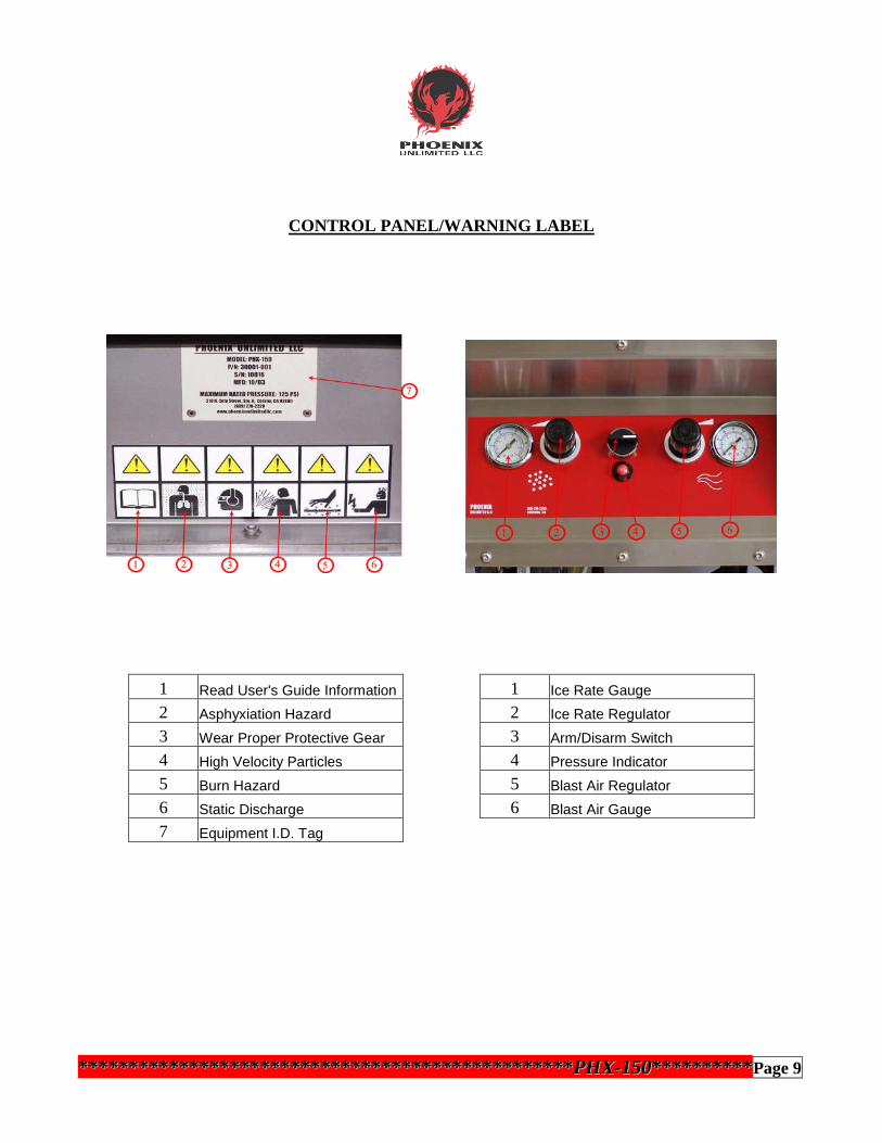
LOADING DRY ICE
1. Before you begin loading dry ice, it is important that you have the protective gearpreviously mentioned in the “Safety Precautions and Warnings” section (page 6).This includes basic items such as earplugs or muffs (or both), eye protection, faceshield, heavy-duty gloves, long sleeves, long pants, and safety shoes. (pic 1)
2. Lift hinged metal lid to expose hopper. BE AWARE OF AND KEEP CLEAR OFPINCH POINTS (pic 2)
3. Use a sturdy scoop or similar device to load dry ice pellets into the hopper. (pic 3)Be careful not to inhale concentrated CO2 gas during the loading process, as it willtemporarily rob you of oxygen. If overexposed, get fresh air immediately. Signsof overexposure include dizziness, cold sweats, headaches, nausea, and heavybreathing.
4. Close the lid on the hopper. This will prevent airborne contaminants frominadvertently falling through the pellet screen to the ice and ultimately ending upon the surface you are cleaning or damaging internal airlock parts. (pic 4)
**************************************************************************************************PPHHXX--115500******************Page 12
Pic 1 Pic 2
Pic 4Pic3

SETTING THE PANEL CONTROLS
Applying Air to the Unit1. Slowly open the main air supply valve (source). (pic1)2. With the gun pointed in a safe direction, slowly open the E-Stop valve on thePHX-150. (pic 2)
Setting the Panel Controls1. Pull the ‘Ice Rate’ knob outwards to unlock it. (pic 1)2. Turn the control clockwise until the gauge reaches the desired pressure. If unsure, startat about 25 psi, then adjust the rate up or down as necessary for your particular blastingapplication. (pic 2) Note: Trigger on gun must be pulled in order for gauge to read!3. Push the knob in to lock the ice rate. (pic 3)
**************************************************************************************************PPHHXX--115500******************Page 13
Pic 2
Pic 1 Pic 2
Pic 3
Pic 1

SETTING THE PANEL CONTROLS (cont.)
4. Next set the blast pressure. Pull the ‘blast pressure’ knob outwards to unlock it. (pic 4)5. Turn the knob clockwise until desired pressure is reached. The PHX-150 has a blastpressure range from 45 psi to 125 psi. Satisfactory results are generally achieved in the80-100 psi range for most applications. If you are unsure or concerned about damage tothe item being blasted, start at a lower blast pressure and increase it gradually until theoptimum performance level is achieved. (pic 5)6. Push the knob in to lock the blast rate. (pic 6)
Note: The PHX-150 utilizes an additional regulator that maintains the blast pressure at45 psi, even if the control panel knob is turned all the way down. This prevents “freeze-ups” in the airlock assembly, which will occur if ice continually feeds withoutsufficient pressure to propel it to the gun.
7. Turn the Arm/Disarm switch clockwise to arm the PHX-150. The indicator will turngreen, and the momentary switch will return to the center position. (pic 7)8. Point the gun at the target or in a safe direction. Push upwards on the safety catch torelease and pull the trigger to initialize blasting. (pic 8)
**************************************************************************************************PPHHXX--115500******************Page 14
Pic 4 Pic 5 Pic 6
Pic 7 Pic 8

TEMPORARY SHUTDOWN
1. When blasting is complete, release the trigger and wait for airflow to stop. (There is ashort delay while residual ice is purged from the blast hose. Keep gun pointed at thetarget until air stops flowing!) (pic 1)2. Turn the Arm/Disarm switch counter-clockwise. The indicator will turn red, and themomentary switch will return to the center position. (pic 2)3. Close the air supply valve at the source. Important! Failure to disconnect the sourceend of the air supply first may create potential “air entrapment” or “hose whip”hazards! (pic 3)4. Vent remaining air from the machine and supply hose by closing theE-Stop valve approximately halfway. (pic 4)5. After the air stops flowing, you may fully close the E-Stop valve. (pic 5)6. If moving the unit to another location for blasting, disconnect the supply hose at thesource and wrap around the machine handle for quick transport. It is not necessary todisconnect the hose from the unit unless storing overnight or long term. (pic 6)
**************************************************************************************************PPHHXX--115500******************Page 15
Pic 1 Pic 2 Pic 3
Pic 4 Pic 5
Pic 6
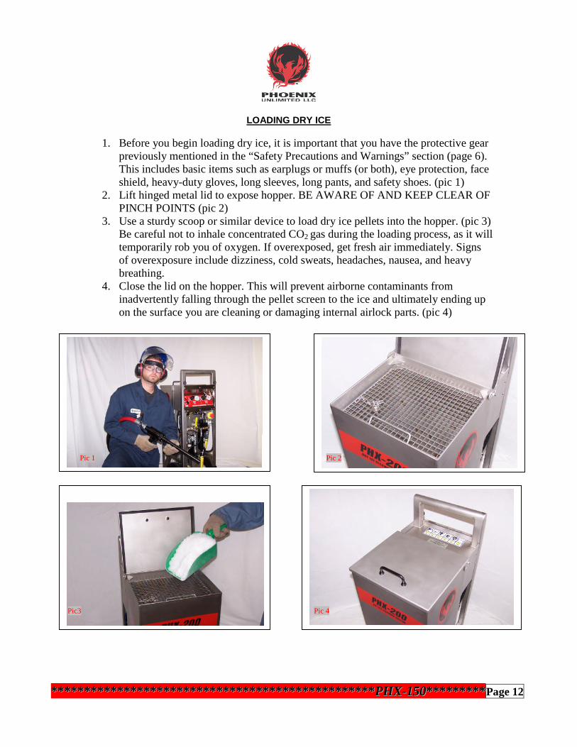
OVERNIGHT / LONG TERM SHUTDOWN
1. If you won’t be blasting again soon, release the trigger and wait for airflow to stop.(There is a short delay while residual ice is purged from the blast hose. Keep gun pointedat the target until air stops flowing!) (pic 1)2. Turn the Arm/Disarm switch counter-clockwise. The indicator will turn red and themomentary switch will return to the center position. (pic 2)3. Remove any unused ice from the hopper with a scoop and return it to the storagecontainer.4. Turn the Arm/Disarm switch clockwise. Indicator will turn green. (pic 3)5. Pull the trigger and expel remaining pellets through the gun. (pic 4)6. Follow steps 2-6 on page 15 to complete the shutdown procedure, then store unit. (textbox)
**************************************************************************************************PPHHXX--115500******************Page 16
FOLLOW STEPS
2-6 ON PAGE 15
TO COMPLETE
Pic 1 Pic 2
Pic 3 Pic 4

MAINTENANCE
CAUTION! Do not attempt to perform any maintenance or service on your PHX-150unless safety guidelines and lock out/tag out procedures have been satisfactorily met!
DAILY PREVENTIVE MAINTENANCEBefore starting the machine each day/shift, a quick preventive maintenance inspectionshould be performed to ensure that your unit operates problem-free now and in the future.1. Check the separator sight glass for accumulated moisture or remove the canister toinspect the filter for contamination. Clean canister if needed. (See page 18 for filterreplacement procedure). (pic 1)2. Visually inspect lubricator to confirm fluid level is adequate. (pic 2)3. Inspect hose assembly for cracks or leaks. Replace if necessary. (pic 3)
AS NEEDED MAINTENANCESeparator / Auto-Drain Leak CheckThe PHX-150 features an “auto-drain” in the separator to relieve excess moisture duringnormal use. The float mechanism should be securely in place with no air leakage underpressure. To check:1. Slowly open the main air supply valve. (pic 1)2. Slowly open the E-Stop valve of the PHX-150. (pic 2)3. Check for air leakage under pressure. If air is present, you may need to clean the auto-drain or replace. Tighten the drain nut securely after replacement. (pic 3)
**************************************************************************************************PPHHXX--115500******************Page 17
Pic 1 Pic 2 Pic 3
Pic 1 Pic 2 Pic 3
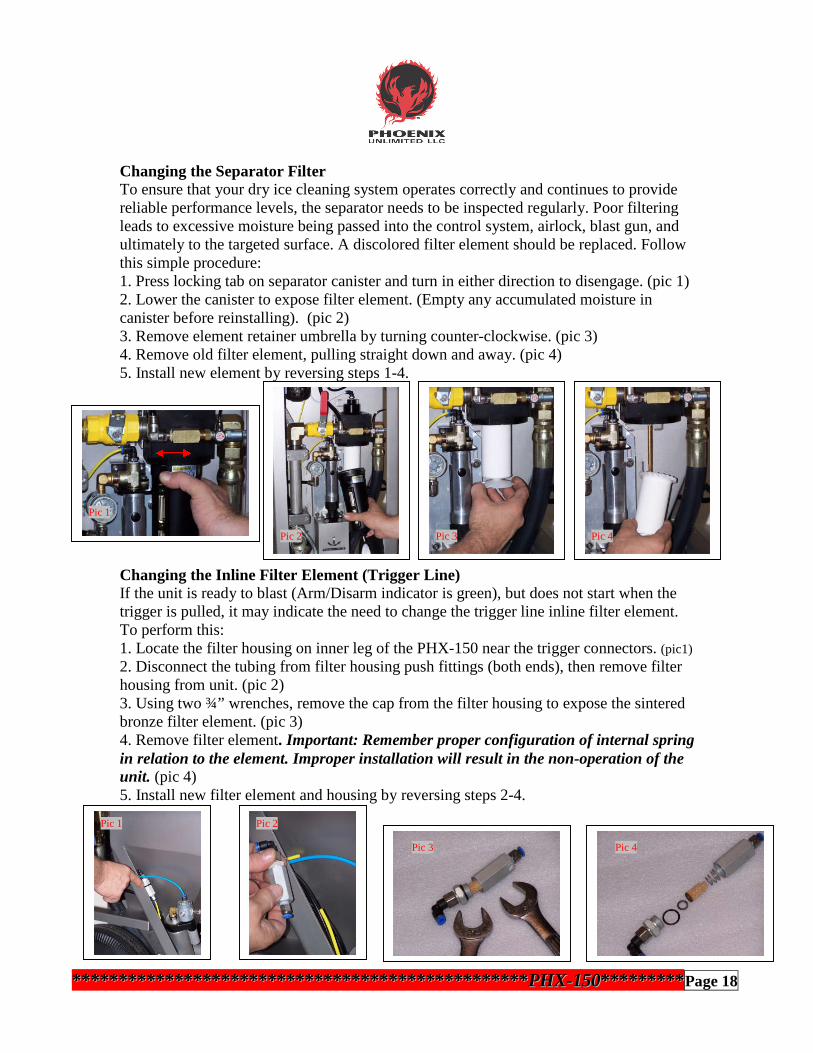
Changing the Separator FilterTo ensure that your dry ice cleaning system operates correctly and continues to providereliable performance levels, the separator needs to be inspected regularly. Poor filteringleads to excessive moisture being passed into the control system, airlock, blast gun, andultimately to the targeted surface. A discolored filter element should be replaced. Followthis simple procedure:1. Press locking tab on separator canister and turn in either direction to disengage. (pic 1)2. Lower the canister to expose filter element. (Empty any accumulated moisture incanister before reinstalling). (pic 2)3. Remove element retainer umbrella by turning counter-clockwise. (pic 3)4. Remove old filter element, pulling straight down and away. (pic 4)5. Install new element by reversing steps 1-4.
Changing the Inline Filter Element (Trigger Line)If the unit is ready to blast (Arm/Disarm indicator is green), but does not start when thetrigger is pulled, it may indicate the need to change the trigger line inline filter element.To perform this:1. Locate the filter housing on inner leg of the PHX-150 near the trigger connectors. (pic1)
2. Disconnect the tubing from filter housing push fittings (both ends), then remove filterhousing from unit. (pic 2)3. Using two ¾” wrenches, remove the cap from the filter housing to expose the sinteredbronze filter element. (pic 3)4. Remove filter element. Important: Remember proper configuration of internal springin relation to the element. Improper installation will result in the non-operation of theunit. (pic 4)5. Install new filter element and housing by reversing steps 2-4.
**************************************************************************************************PPHHXX--115500******************Page 18
Pic 1
Pic 2 Pic 3 Pic 4
Pic 1 Pic 2
Pic 3 Pic 4

Changing / Adding 10W Oil1. Turn the lubricator retaining ring counter-clockwise by hand, then lower thebowl/housing away from suction wick. (pic 1)2. Add 10W tool oil (or equivalent) until level with fill line. (pic 2)3. Be sure that the O-ring is properly seated in the top of the lubricator bowl. (pic 3)4. Reinstall the bowl/housing into place. Hand tighten only. Do not over tighten. (pic 4)
Checking / Adjusting the Drive Chain Tension1. Use a 5/32” hex key wrench to loosen two screws located at the top of the motor/chainguard. Do not remove the screws. (pic 1)2. Gently tilt the unit forward and remove third screw located at the bottom of the guard.(pic 2)3. Remove the chain guard to reveal drive chain. (pic 3)4. Apply pressure to mid-span point. Movement should not be more than 3/32”. (pic 4)5. If tension adjustment is necessary, loosen the two upper hex screws on the motormounting plate. (pic 5)6. Locate the drive chain adjustment screw at the very top of the motor mounting plate.(pic 6)
(continued)
**************************************************************************************************PPHHXX--115500******************Page 19
Pic 1 Pic 2 Pic 3 Pic 4
Pic 1 Pic 2 Pic 3
Pic 4 Pic 5 Pic 6

Checking / Adjusting the Drive Chain Tension (cont.)7. Use a 7/16” box wrench to loosen the adjustment screw retaining nut by turningcounter-clockwise. (pic 7)8. Hold the retaining nut in position and use a 3/16” hex key wrench to adjust the screw(clockwise to increase tension, counter-clockwise to relieve) until proper tension isachieved. (pic 8)9. Tighten the retaining nut to lock the adjustment screw into place. (pic 9)10. Tighten the two upper hex screws on the motor mounting plate. (pic 10)11. Verify that the auger directional switch on motor ratchet is rotated fully clockwise.(pic 11)12. Install the motor/chain guard into position. (pic 12)13. Tighten the three screws that secure the guard into place. (pic 13)
**********************************************************************************************PPHHXX--115500******************Page 20
Pic 7 Pic 8 Pic 9
Pic 10Pic 11
Pic 12 Pic 13

PERIODIC MAINTENANCE
CAUTION! Do not attempt to perform any maintenance or service on your PHX-150unless safety guidelines and lock out/tag out procedures have been satisfactorily met!
Replacing Airlock Critical ComponentsDiminished performance or a noticeable drop in blast pressure at the gun may indicate aworn or damaged component in the airlock. Most airlock problems are typically causedby a foreign object (airborne or otherwise) falling through the hopper pellet screen,mixing with the dry ice pellets, and becoming lodged inside the airlock or doing damageas it passes through to the blast hose and gun. (Note: You can avoid unnecessaryexpense and repairs by closing the hopper lid after filling with ice and prior toblasting.) In order to properly inspect or replace the critical components, the airlockassembly must be removed from the unit. To do this:1. Remove air supply hose from the PHX-150. Also remove the gun and blast hoseassembly if attached. (pic 1)2. To avoid spillage, remove the lubricator bowl/housing and set aside. (pic 2)3. Carefully place the unit flat on the ground with the control panel facing down.(pic 3). Be careful that hinged metal lid does not “flop” backwards suddenly during thisprocedure.4. Detach the inlet blast air hose coupling from airlock assembly inlet. (pic 4)5. Remove the airlock motor air supply line from the push fitting. (pic 5)6. Remove the large cotter pin from the airlock retaining latches. (pic 6)
**************************************************************************************************PPHHXX--115500******************Page 21
Pic 1 Pic 2 Pic 3
Pic 4 Pic 5 Pic 6

Replacing Airlock Critical Components (cont.)7. Open airlock retaining latches. (pic 7)8. Remove complete airlock assembly from unit and move it to a workbench. (pic 8)9. Use a 3/16” hex key wrench to remove six housing bolts from bottom of airlockassembly. (pic 9)10. Separate the housing and set bottom half aside. (pic 10)
Rotor:11. Carefully remove the rotor from thespline and inspect. Replace if damaged.Before installation of new rotor, clean andinspect the pads, motor, spline and internalwalls of the housing for damage. If all partsare good, install the new rotor onto thespline. (pic 11)12. Reinstall airlock assembly onto thePHX-150 by reversing steps 1-10. (text box)
Airlock Motor / Spline:13. While the housing is disassembled, inspect the motor and spline. If replacement isnecessary, the motor will need to be removed from the housing. (pic 12)14. Use a ¼” hex key wrench to remove the two mounting screws, then remove the motorassembly from the mounting block. (pic 13)15. Use two 13/16” wrenches (1 tappet) to remove the spline from the motor and installnew one. (Note: Don’t forget the spacer ring between the motor jam nut and the spline!)(pic 14)16. Reinstall airlock assembly by reversing steps 1-11. (text box)
**************************************************************************************************PPHHXX--115500******************Page 22
REINSTALLAIRLOCKASSY. BYREVERSINGSTEPS 1-10
REINSTALLAIRLOCKASSY. BYREVERSINGSTEPS 1-11
Pic 7 Pic 8 Pic 9 Pic 10
Pic 11
Pic 12 Pic 13 Pic 14

Replacing Airlock Critical Components (cont.)
Airlock Pads:17. While the housing is disassembled, inspect the airlock pads (2) located in each half ofthe housing. If damaged, they must be replaced. (pic 15)18. Remove the pads from the housing. (pic 16)19. Inspect the O-rings on both pads. Replace if worn or damaged. Before installing newO-rings (or re-using existing ones), apply a thin coat of Dow-Corning 33 lubricant.(pic 17)20. Make sure that O-rings are seated properly in the pads. (pic 18)21. Carefully install the pads into the airlock housing. Fully installed, they will be flushwith the housing walls, with no part of the O-rings showing. (pic 19)22. Reinstall airlock assembly onto the PHX-150 by reversing steps 1-11. (text box)
**************************************************************************************************PPHHXX--115500******************Page 23
REINSTALL AIRLOCK
ASSY. BY REVERSING
STEPS 1-11
Pic 15 Pic 16
Pic 17 Pic 18
Pic 19

TROUBLESHOOTING
Symptom Item Check Corrective MeasureThe PHX-150 willnot start.
Air supply valve is not opened.
The unit is not armed (indicator will bered).
Pellet screen is not properly installed.
Loose or kinked tubing in control panel.
Trigger lines improperly connected.
Trigger valve failure.
Inline filter plugged (trigger return line).
Contamination in the trigger lines.
Open the air supply valve (E-Stop valve).
Turn Arm/Disarm switch clockwise (indicator shouldturn green).
Make sure pellet screen fully engages safety interlockswitch when installed.
Check for loose or kinked tubes behind panel.Reconnect if necessary.
Check trigger lines at machine and at the gun.
Check trigger valve for contamination. Clean orreplace as necessary. Correct cause of contamination.
Check filter and replace element if necessary.
Blow out trigger lines. Correct cause of contamination.
The PHX-150 starts,but no ice comes out.
There is no dry ice in the hopper.
Ice rate is set too low.
Possible ice bridging inside the hopper.
Water ice accumulation in hopper.
Blast gun or hose plugged.
Incorrect auger rotation. (Auger shouldturn counterclockwise when viewed fromthe rear of the unit).
Airlock is not turning.
Load fresh dry ice into the hopper.
Turn Ice rate regulator clockwise to increase.
With pellet screen in place, use poker to break up thebridge. This symptom is generally caused by poor icequality and high humidity areas.
Water ice forms in high humidity areas or when ice isleft in the hopper for long periods of time. Clean anddry the hopper thoroughly before refilling.
Decrease blast pressure to 45 psi. Remove blast hosefrom unit. With trigger lines still attached, trigger theunit to clear ice from the discharge outlet. Reattachhose and remove nozzle from gun. Trigger again toclear ice from hose and gun. Reattach nozzle.
Remove motor/chain guard and turn selector switchon ratchet motor to reverse direction.
See section on “Airlock does not turn”- next page.
************************************************************************************************************************PPHHXX--115500******************PPaaggee 2244

TROUBLESHOOTING (cont.)
SSyymmttoomm IItteemm CChheecckk CCoorrrreeccttiivvee MMeeaassuurreePPeelllleettss ssttoopp fflloowwiinnggaafftteerr aa ppeerriioodd ooffbbllaassttiinngg..
TThheerree iiss nnoo ddrryy iiccee lleefftt iinn tthhee hhooppppeerr..
PPeelllleettss hhaavvee bbrriiddggeedd oovveerr aauuggeerr iinnssiiddeehhooppppeerr..
BBllaasstt hhoossee oorr gguunn pplluuggggeedd..
AAuuggeerr nnoott ttuurrnniinngg..
AAiirrlloocckk nnoott ttuurrnniinngg..
LLooaadd ddrryy iiccee iinnttoo hhooppppeerr..
WWiitthh ppeelllleett ssccrreeeenn iinn ppllaaccee,, uussee ppookkeerr ttoo bbrreeaakk uupp tthheebbrriiddggee.. PPoooorr iiccee qquuaalliittyy aanndd hhiigghh hhuummiiddiittyy ggeenneerraallllyyccaauussee tthhiiss pprroobblleemm..
DDeeccrreeaassee bbllaasstt pprreessssuurree ttoo 4455 ppssii.. RReemmoovvee bbllaasstt hhoosseeffrroomm uunniitt.. WWiitthh ttrriiggggeerr lliinneess ssttiillll aattttaacchheedd,, ttrriiggggeerr tthheeuunniitt ttoo cclleeaarr iiccee ffrroomm tthhee ddiisscchhaarrggee oouuttlleett.. RReeaattttaacchhhhoossee aanndd rreemmoovvee nnoozzzzllee ffrroomm gguunn.. TTrriiggggeerr aaggaaiinn ttoocclleeaarr iiccee ffrroomm hhoossee aanndd gguunn.. RReeaattttaacchh nnoozzzzllee..
SSeeee sseeccttiioonn ““AAuuggeerr ddooeess nnoott ttuurrnn”” bbeellooww..
SSeeee sseeccttiioonn ““AAiirrlloocckk ddooeess nnoott ttuurrnn”” bbeellooww..
BBllaasstt gguunn pplluuggssrreeppeeaatteeddllyy..
IIccee rraattee sseett ttoooo hhiigghh..
PPoossssiibbllee wwaatteerr iiccee aaccccuummuullaattiioonn iinnssiiddeegguunn..
DDeeccrreeaassee iiccee rraattee..
DDeeffrroosstt,, cclleeaann,, aanndd ddrryy tthhee gguunn.. CChheecckk iinnccoommiinngg aaiirrssuuppppllyy ffoorr ccaauussee ooff ccoonnttaammiinnaattiioonn aanndd ccoorrrreecctt..
AAuuggeerr ddooeess nnoott ttuurrnn.. IIccee rraattee sseett ttoooo llooww..
IInnccoorrrreecctt ddrriivvee cchhaaiinn tteennssiioonn..
LLoossss ooff aaiirr ssuuppppllyy ttoo tthhee ddrriivvee mmoottoorr..
SSuuppppllyy aaiirr iiss ttoooo llooww..
IInnccrreeaassee iiccee rraattee..
CChheecckk aanndd aaddjjuusstt cchhaaiinn tteennssiioonn.. ((ppaaggeess 1199--2200))
CChheecckk ssuuppppllyy aaiirr ttoo tthhee ddrriivvee mmoottoorr iinnppuutt.. IIff nneeeeddeedd,,ccoonnttaacctt PPhhooeenniixx UUnnlliimmiitteedd ffoorr ssuuppppoorrtt..
MMaakkee ssuurree ssuuppppllyy aaiirr iiss aatt lleeaasstt 7755 ppssii tthhrroouugghh aa 11””uunnrreessttrriicctteedd lliinnee..
AAiirrlloocckk ddooeess nnoott ttuurrnn.. LLoossss ooff aaiirr ssuuppppllyy ttoo tthhee aaiirrlloocckk mmoottoorr..
EExxhhaauusstt mmuufffflleerr iiss pplluuggggeedd..
EExxcceessssiivvee ccoonnttaammiinnaattiioonn ooff tthhee aaiirrlloocckk..
CChheecckk ssuuppppllyy aaiirr ttoo tthhee aaiirrlloocckk mmoottoorr iinnppuutt.. IIff nneeeeddeedd,,ccoonnttaacctt PPhhooeenniixx UUnnlliimmiitteedd ffoorr ssuuppppoorrtt..
RReemmoovvee,, ddiissaasssseemmbbllee,, cclleeaann,, aanndd rreeiinnssttaallll..
RReemmoovvee aaiirrlloocckk,, cclleeaann oorr rreeppllaaccee ppaarrttss..((ppaaggeess 2211--2233))
BBllaasstt pprreessssuurree aanndd//oorriiccee rraattee ddrrooppss qquuiicckkllyywwhheenn ttrriiggggeerr iiss ppuulllleedd..
AAiirr ssuuppppllyy lliinnee iiss lleessss tthhaann 11”” oorr tthheerree iissaa rreessttrriiccttiioonn ssmmaalllleerr tthhaann 11”” bbeettwweeeenn tthheeuunniitt aanndd tthhee ccoommpprreessssoorr..
CChheecckk ssuuppppllyy ttoo vveerriiffyy aa 11”” uunnrreessttrriicctteedd lliinnee ffrroomm tthheeuunniitt ttoo tthhee ccoommpprreessssoorr.. DDiissttaanncceess oovveerr 110000 ffeeeett mmaayyeevveenn bbee ooff llaarrggeerr ddiiaammeetteerr..
BBllaasstt pprreessssuurree aanndd//oorriiccee rraattee ddrrooppss sslloowwllyywwhheenn ttrriiggggeerr iiss ppuulllleedd..
IInnddiiccaatteess aann uunnddeerrssiizzeedd ccoommpprreessssoorr.. IIff tthhee pprreessssuurree ddrroopp hhaass aa ssiiggnniiffiiccaanntt aaddvveerrssee eeffffeeccttoonn cclleeaanniinngg ppeerrffoorrmmaannccee,, aa llaarrggeerr ccoommpprreessssoorr mmaayybbee rreeqquuiirreedd..
************************************************************************************************************************PPHHXX--115500******************Page 25

************************************************************************************************************************PPHHXX--115500******************Page 26

ITEM P/N DESCRIPTION QTY
1 30025-002 Frame,Complete,PHX-150 12 30100-KIT LidAssy., PHX-150w/ mountinghardware 13 30002-001 Screen,Pellet,PHX 14 30089-001 Poker Assy.,PHX 15 30003-001 ValveAssy.,SafetyScreen 16 30029-001 Control Panal Assembly,PHX-150 17 30016-001 Control Shelf Assembly 18 30024-001 Air SystemAssembly,PHX-150 19 50061-001 HoseWhipCheck 110 20013-012 Wheel,12"Dia. 211 20009-004 Caster, Conductive 212 30017-001 AirlockAssembly,PHX-150 113 30006-001 Driveassembly, Auger 114 30049-001 HoseAssembly,AirlockSupply 115 20011-K35 Bumper,Recessed 216 30004-001 Auger,PHX 117 30005-001 Bearing,UHMW 1
P/N30150-025PHX-150DRYICECLEANINGSYSTEM
************************************************************************************************************************PPHHXX--115500******************Page 27

ITEM P/N DESCRIPTION QTY1 30030-001 Panel,PHX-150 12 30032-001 Regulator, Auger Quick Strat 13 50006-007 Selector,3 Position,Momentary 14 50007-001 Logic Element,"OR" 15 50012-015 Mounting Ring for Valve Bodies 16 50111-911 Valve Body,Normally Non Passing 17 50111-912 Valve Body,Normally Passing 18 50016-002 Elbow,Male,5/32T x 1/8"NPT 19 50017-002 Tee,Male Swivel,5/32T x 1/8"NPT 110 50018-001 Elbow,female,5/32T x 1/8"NPT 211 50025-100 Gauge, 1.5",100 PSIG 112 50025-160 Gauge, 1.5",160 PSIG 113 50027-212 Indicator,Pressure,1/8" NPT 114 50034-001 Connector,Female,Barbed,5/32T x 1/4"NPT Brass 115 50051-001 Regulator, Relieving,1/4" 116 50057-628 Elbow,Male,3/8T x 1/4"NPT 217 50069-001 Nut,Regulator 2
P/N 30029-001Control Panel Assembly, PHX-150
************************************************************************************************************************PPHHXX--115500******************Page 28

************************************************************************************************************************PPHHXX--115500******************Page 29
ITEM P/N DESCRIPTION QTY1 50026-001 Air Reservoir 12 30105-001 Lubricator, w/ mounting holes 13 50023-001 Logic Element,OR 24 50023-003 Logic Element,NOT 15 50023-004 Logic Element,YES 56 40003-003 Din Rail 7"7 40002-K12 End Section (not used) 18 50050-001 Timer,Pneumatic 19 50050-002 Base,Timer 110 50050-003 Din Mount,Timer 111 50044-001 Regulator,1/4"NPT 112 50057-628 Elbow,Male,Swivel,3/8T x 1/4"NPT 113 50055-628 Tee,Male Run,Swivel,3/8T x 1/4"NPT 114 50037-001 Elbow,Street,1/8"NPT,Brass 115 50019-002 Y,Male,5/32T x 1/8"NPT 216 50030-002 Elbow,4 Way,5/32T x1/4"NPT 217 50003-001 Reducer,1/4"NPT x 1/8"NPT, Brass 218 50029-004 Bulkhead,Female,1/4T x 1/4"NPT 119 50029-002 Bulkhead,Female,5/32T x 1/4"NPT 120 50021-002 Speed Controller 121 50016-002 Elbow,Male,5/32T x 18"NPT 122 50057-638 Elbow,Male,Swivel,3/8T x 3/8"NPT 223 40007-001 Timer, LCD (not shown) 124 50073-001 Pressure Switch (not shown) 1
P/N 30016-001Control Shelf Assemblylf Assembly, PHX-150

************************************************************************************************************************PPHHXX--115500******************Page 30
ITEM P/N DESCRIPTION QTY
1 50009-007 Elbow,1"NPT 1
2 50043-105 Nipple,Pipe,1"NPT x 10.5", SS 1
3 30087-001 Elbow,Street,1”NPT,Modified 1
4 50039-016 Elbow,1"NPT x 1"JIC 1
5 50042-016 Valve,Ball,Vented,1"NPT 1
6 50060-221 Nipple,Pipe,1"NPT x 1.5", SS 1
7 30060-001 Filter/Regulator Assembly 1
8 50066-002 Connector,Female,5/32T x 1/4"NPT 1
9 50016-003 Elbow,Male,5/32T x 1/4"NPT 1
10 50067-002 Filter,In-Line,1/4"NPT 1
11 50004-002 Elbow,Male,1/4"NPT,Brass 1
12 50057-628 Elbow,Male,Swivel,3/8T x 1/4"NPT 1
13 50005-004 Tee,Male Branch,Short,1/4"NPT 1
14 50052-002 Regulator,w/gauge,1/8"NPT 1
15 50037-001 Elbow,Street,1/8" NPT 1
16 50003-001 Pipe Reducer,1/4 x 1/8 1
P/N 30024-001
Air System Assembly, PHX-150
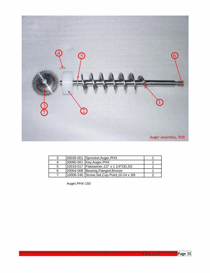
3 30035-001 Sprocket,Auger,PHX 14 30090-001 Key,Auger,PHX 15 10019-017 Flatwasher,1/2" x 1 1/4"OD,SS 16 20004-008 Bearing,Flanged,Bronze 17 10006-240 Screw,Set,Cup Point,10-24 x 3/8 2
Auger,PHX-150
************************************************************************************************************************PPHHXX--115500******************Page 31

ITEM P/N DESCRIPTION QTY
1 30010-001 Plate,Motor Mount 1
2 30006-002 Bearing and Sprocket Assembly 1
3 30088-001 Ratchet Assembly 1
4 30008-001 Support Block,Auger Drive 1
5 30007-001 Clamp,Support Block,Auger Drive 1
6 30009-001 Tension Block,Auger Drive 1
7 30011-001 Bracket,Auger Drive 1
8 30012-001 Adjustment Plate,Auger Drive 1
9 20006-001 Chain,Drive 1
10 20006-002 Link,Chain 1
11 50016-002 Elbow,Male,5/32 x 1/8"NPT 1
12 50001-005 Elbow,Street,1/4"NPT,Brass 1
13 50060-131 Nipple,Pipe,SS,1/4"NPT 1
14 50057-628 Elbow,Male,Swivel,3/8T x 1/4"NPT 1
15 50040-002 Tee,Street,1/4"NPT 1
16 50016-003 Elbow,Male,5/32 x 1/4"NPT 1
17 50053-001 Valve,Poppet,1/4"NPT 1
18 50002-004 Pipe Plug,1/4"NPT 1
P/N 30006-001
Drive Assembly, Auger,PHX-150
************************************************************************************************************************PPHHXX--115500******************Page 32

ITEM P/N DESCRIPTION QTY
1 30019-001 Airlock Housing, Inlet Side 1
2 30018-001 Airlock Housing, Outlet Side 1
3 30022-001 Rotor, Airlock 1
4 30034-001 Pad, Airlock Sealing 2
5 30021-001 Saddle, Airlock Mount 1
6 30036-001 Discharge Tube 1
7 30023-001A Shaft, Airlock Drive 1
8 30068-001 Motor Adapter, Airlock 1
9 10013-035 O-Ring 2
10 10011-327 Quad-Ring 2
11 10014-T11 Eyebolt 2
12 20010-A41 Latch, Draw 2
13 10013-222 O-Ring 1
14 50047-100 Motor, Airlock 1
15 50053-001 Valve, Poppet 1
16 50004-002 Elbow,Male,1/4"NPT 1
17 50057-628 Elbow,Male,Swivel,3/8T x 1/4"NPT 1
18 50015-002 Connector,Male,5/32T x 1/8"NPT 1
19 N/A Spacer, Airlock Motor- (no longer needed) 0
20 50039-016 Elbow,1"NPT x 1"JIC 1
21 10025-B10 Dowel Pin 2
P/N 30017-001
Airlock Assembly, PHX-150
************************************************************************************************************************PPHHXX--115500******************Page 33

ITEM P/N DESCRIPTION QTY1 50063-003 Vibrator,Impact 12 50060-131 Nipple,Pipe,SS,1/4"NPT 13 50016-002 Elbow,Male,5/32T x 1/8"NPT 14 50053-001 Valve,Poppet,1/4"NPT 15 50056-628 Connector,Male,3/8T x 1/4"NPT 16 50059-002 Muffler,Exhaust,1/4"NPT 17 30031-001 Pad,Vibrator,PHX 18 50002-Z04 Pipe Plug,1/4"NPT 1
P/N 30028-001Vibrator Assembly,PHX-150
************************************************************************************************************************PPHHXX--115500******************Page 34

ITEM P/N DESCRIPTION QTY1 30051-001 Retaining Coller,Gun,PHX 12 30052-001 Shaft,Ice,Gun,PHX 13 30053-001 Cap, Nozzle Retainer 14 30054-001 Retainer,Cap 15 30055-001 Outlet,Gun 16 30056-001 Gun Body 17 30057-001 Handle,Gun 18 30067-001 Shim,Gun 29 50068-001 Trigger Valve 110 20008-001 Bearing,Flanged,I-Glide 211 20002-001 Bearing,Thrust,Gun 112 20001-001 Trigger Lever 113 10030-219 O-Ring, Double Seal,Viton 114 10007-H06 Screw,Button Head Socket 115 10028-006 Spring, Torsion 116 10029-034 Retaining Ring, Spiral 117 50014-002 Connector,Barbed,10-32 x 1/4T 118 50014-001 Connector,Barbed,10-32 x 5/32T 119 50022-2BK Tubing,Polyurethane,5/32 220 50070-4BK Tubing,Polyurethane,1/4" x 1/8"ID 221 50065-001 Union,5/32T 122 50065-003 Union,1/4T 123 30091-001 Gasket,Gun Handle 1
P/N 30083-001Gun Assembly,PHX-150
************************************************************************************************************************PPHHXX--115500******************Page 35
30083-001

x
b
A
a
b
A
a
b
A
x
a
A
x
a
A
x
a
A
x
a
Aab
A
x
a
A
12
t
TOAIR
L OC
K
L-1L-2
L-3L-4
L-5L-6
L-7L-8
T-1
L-9
S-1
REG
-1
FCV
-1A
T-1
F-1
V-1
F-2
REG
-2
RE G
-3
L UB
E-1
REG
-4
F-3
PI -1
V-2
AT-2
PI-2M
-1
M-2
VB
-1
PV-1
REG
- 5
PI-3
RES
-1
PV-2
PV- 3
12
3
3
4
5
67
8
91
0
11
11
12
13
14
14
15
16
18
18
19
20
22
23
24
25
25
26
27
28
17
29
30
31
32
33
34
35
36
37
38
39
40
41
42
43
43
42
44
45
46
PH
X-1
50
FL
OW
SC
HE
MA
TIC
30
00
0-S
CH
RE
VA
21
PHO
ENIX
UN
LIMITED
L LC
1
34
1
2
ETMPS
1
1
4
************************************************************************************************************************PPHHXX--115500******************Page 36

PHX-150 FLOW SCHEMATIC COMPONENT REFERENCE
REFERENCE DESCRIPTION FUNCTION PART #
L-1L-3L-4L-6L-7
LOGIC ELEMENT-YES CONTROL SYSTEM 50023-004
L-2L-5 LOGIC ELEMENT-OR CONTROL SYSTEM 50023-001
L-8 LOGIC ELEMENT-NOT CONTROL SYSTEM 50023-003
T-1 TIMER VIBRATOR CONTROL 50050-001
V-1V-2
BALL VALVE, RELIEVINGLEVER OPERATED VALVEN
E-STOPPELLET SCREEN
50042-01630003-002
FCV-1 FLOW CONTROL VALVE PURGE DELAY 50021-002
AT-1AT-2
AIR TANKAIR TANK
PURGE DELAYVIBRATOR CONTROL
50026-00150026-002
ETM TIMER, LCD ELAPSED TRIGGER TIME 40007-001
PS-1 PRESSURE SWITCH ETM CONTROL 50073-001
S-1 SELECTOR SWITCH SYSTEM ARM SEE PANEL
F-1F-2F-3
FILTERFILTERFILTER
BLAST PILOTMAIN
TRIGGER
50067-00230060-00150067-001
PI-1 PRESSURE INDICATOR SYSTEM ARM 50027-212
RES-1 RESTRICTOR VIBRATOR CONTROL 50036-001
REG-1REG-2REG-3REG-4REG-5
REGULATOR, PILOTREGULATOR, CUSTOMREGULATOR, MICRO
REGULATORREGULATOR, CUSTOM
BLAST AIRBLAST AIR
CONTROL SYSTEMAIRLOCK/PURGE
ICE FEED RATE
50051-00130060-00150052-00250044-00130032-001
LUBE-1 LUBRICATOR MOTORS 30105-001
L-9 LOGIC ELEMENT-OR CONTROL SYSTEM 50007-001
PV-1PV-2PV-3
POPPET VALVE
AIRLOCK MOTORVIBRATOR
AUGER50053-001
M-1M-2 MOTOR
AIRLOCKAUGER
50047-10030088-001
30000-SCH.DOC
************************************************************************************************************************PPHHXX--115500******************Page 37
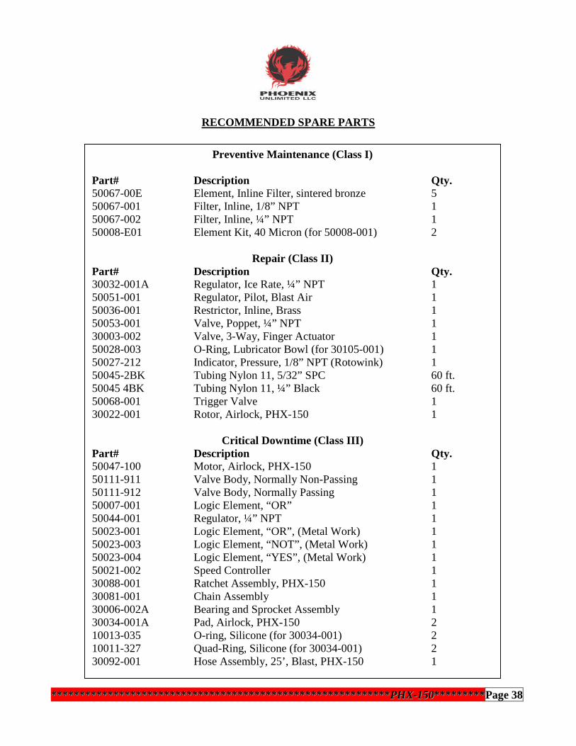
RECOMMENDED SPARE PARTS
************************************************************************************************************************PPHHXX--115500******************Page 38
Preventive Maintenance (Class I)
Part# Description Qty.50067-00E Element, Inline Filter, sintered bronze 550067-001 Filter, Inline, 1/8” NPT 150067-002 Filter, Inline, ¼” NPT 150008-E01 Element Kit, 40 Micron (for 50008-001) 2
Repair (Class II)Part# Description Qty.30032-001A Regulator, Ice Rate, ¼” NPT 150051-001 Regulator, Pilot, Blast Air 150036-001 Restrictor, Inline, Brass 150053-001 Valve, Poppet, ¼” NPT 130003-002 Valve, 3-Way, Finger Actuator 150028-003 O-Ring, Lubricator Bowl (for 30105-001) 150027-212 Indicator, Pressure, 1/8” NPT (Rotowink) 150045-2BK Tubing Nylon 11, 5/32” SPC 60 ft.50045 4BK Tubing Nylon 11, ¼” Black 60 ft.50068-001 Trigger Valve 130022-001 Rotor, Airlock, PHX-150 1
Critical Downtime (Class III)Part# Description Qty.50047-100 Motor, Airlock, PHX-150 150111-911 Valve Body, Normally Non-Passing 150111-912 Valve Body, Normally Passing 150007-001 Logic Element, “OR” 150044-001 Regulator, ¼” NPT 150023-001 Logic Element, “OR”, (Metal Work) 150023-003 Logic Element, “NOT”, (Metal Work) 150023-004 Logic Element, “YES”, (Metal Work) 150021-002 Speed Controller 130088-001 Ratchet Assembly, PHX-150 130081-001 Chain Assembly 130006-002A Bearing and Sprocket Assembly 130034-001A Pad, Airlock, PHX-150 210013-035 O-ring, Silicone (for 30034-001) 210011-327 Quad-Ring, Silicone (for 30034-001) 230092-001 Hose Assembly, 25’, Blast, PHX-150 1

SPECIFICATIONS
Dimensions: 18” x 20” x 47” (W x L x H)(47cm x 51cm x 120cm)
Dry Weight: 140 lbs. (63.5 kg)Hopper Capacity: Over 100 lbs. (45.5 kg) of pelletsIce Consumption Range: 0.5 lbs. – 7 lbs. (0.23 kg – 3.2 kg) / min.Supply Air Pressure Range: 70 psi – 125 psi (4.8 bar – 8.6 bar)Air Consumption Range: 100 CFM – 250 CFMBlast Pressure Range: 50 psi – 125 psi (2.8 bar – 8.6 bar)Inlet Air Temperature: 140°F (60°C) maximumInlet Air Connection: 1” NPT
Customer Support:(951) 278-2229
************************************************************************************************************************PPHHXX--115500******************Page 39

310 N. Cota Street, Suite H Corona, CA. 92880Telephone: (951) 278-2229 Fax: (951) 278-0084
http://www.phoenixunlimitedllc.com