Embed Size (px)
Citation preview
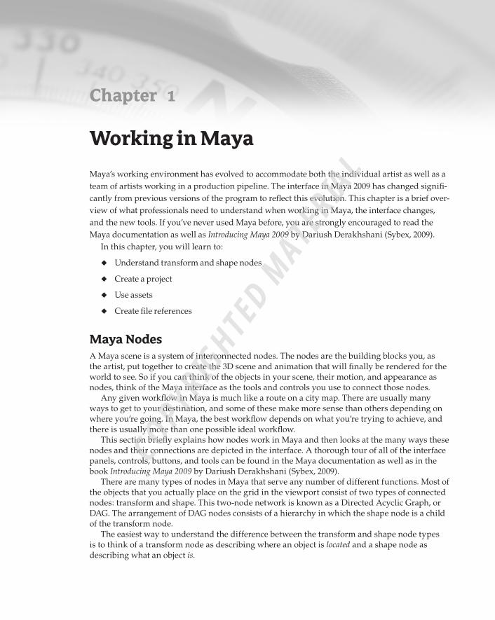
Chapter 1
Working in Maya
Maya’s working environment has evolved to accommodate both the individual artist as well as a team of artists working in a production pipeline. The interface in Maya 2009 has changed signifi-cantly from previous versions of the program to reflect this evolution. This chapter is a brief over-view of what professionals need to understand when working in Maya, the interface changes, and the new tools. If you’ve never used Maya before, you are strongly encouraged to read the Maya documentation as well as Introducing Maya 2009 by Dariush Derakhshani (Sybex, 2009).
In this chapter, you will learn to:
Understand transform and shape nodes•u
Create a project•u
Use assets•u
Create file references•u
Maya NodesA Maya scene is a system of interconnected nodes. The nodes are the building blocks you, as the artist, put together to create the 3D scene and animation that will finally be rendered for the world to see. So if you can think of the objects in your scene, their motion, and appearance as nodes, think of the Maya interface as the tools and controls you use to connect those nodes.
Any given workflow in Maya is much like a route on a city map. There are usually many ways to get to your destination, and some of these make more sense than others depending on where you’re going. In Maya, the best workflow depends on what you’re trying to achieve, and there is usually more than one possible ideal workflow.
This section briefly explains how nodes work in Maya and then looks at the many ways these nodes and their connections are depicted in the interface. A thorough tour of all of the interface panels, controls, buttons, and tools can be found in the Maya documentation as well as in the book Introducing Maya 2009 by Dariush Derakhshani (Sybex, 2009).
There are many types of nodes in Maya that serve any number of different functions. Most of the objects that you actually place on the grid in the viewport consist of two types of connected nodes: transform and shape. This two-node network is known as a Directed Acyclic Graph, or DAG. The arrangement of DAG nodes consists of a hierarchy in which the shape node is a child of the transform node.
The easiest way to understand the difference between the transform and shape node types is to think of a transform node as describing where an object is located and a shape node as describing what an object is.
92201c01.indd 1 3/9/09 11:06:44 AM
COPYRIG
HTED M
ATERIAL
2 | Chapter 1 Working in Maya
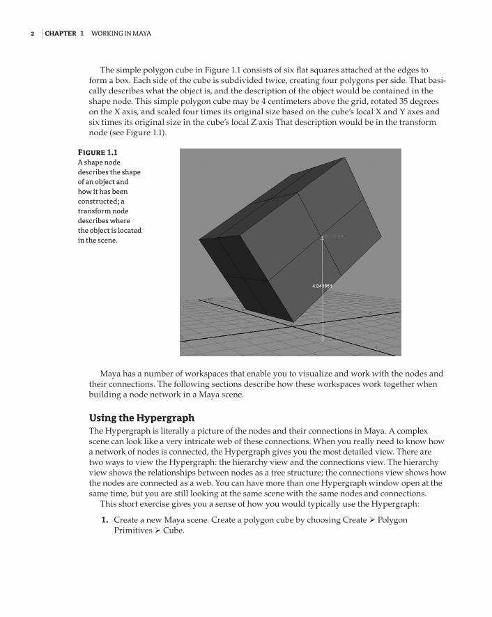
The simple polygon cube in Figure 1.1 consists of six flat squares attached at the edges to form a box. Each side of the cube is subdivided twice, creating four polygons per side. That basi-cally describes what the object is, and the description of the object would be contained in the shape node. This simple polygon cube may be 4 centimeters above the grid, rotated 35 degrees on the X axis, and scaled four times its original size based on the cube’s local X and Y axes and six times its original size in the cube’s local Z axis That description would be in the transform node (see Figure 1.1).
Maya has a number of workspaces that enable you to visualize and work with the nodes and their connections. The following sections describe how these workspaces work together when building a node network in a Maya scene.
Using the HypergraphThe Hypergraph is literally a picture of the nodes and their connections in Maya. A complex scene can look like a very intricate web of these connections. When you really need to know how a network of nodes is connected, the Hypergraph gives you the most detailed view. There are two ways to view the Hypergraph: the hierarchy view and the connections view. The hierarchy view shows the relationships between nodes as a tree structure; the connections view shows how the nodes are connected as a web. You can have more than one Hypergraph window open at the same time, but you are still looking at the same scene with the same nodes and connections.
This short exercise gives you a sense of how you would typically use the Hypergraph:
1. Create a new Maya scene. Create a polygon cube by choosing Create Polygon Primitives Cube.
Figure 1.1 A shape node describes the shape of an object and how it has been constructed; a transform node describes where the object is located in the scene.
92201c01.indd 2 3/9/09 11:06:44 AM
Maya nodes | 3
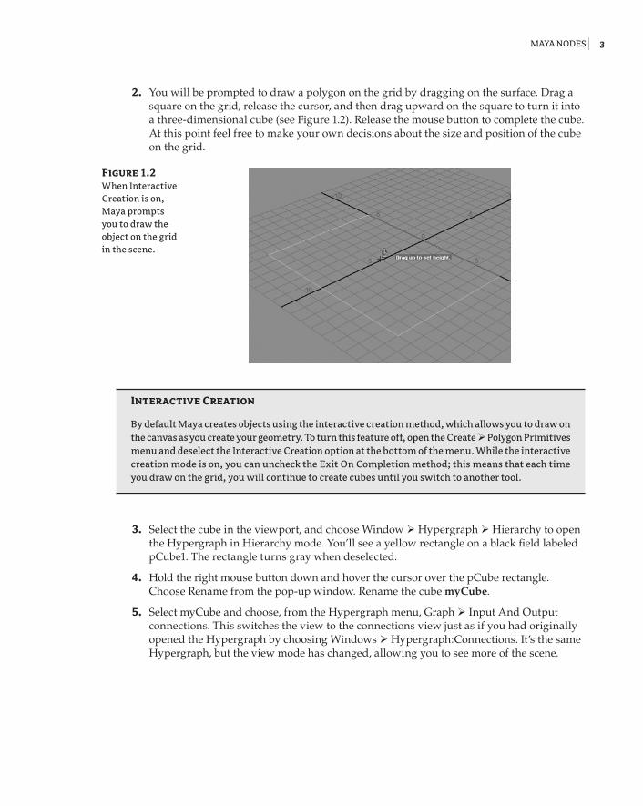
2. You will be prompted to draw a polygon on the grid by dragging on the surface. Drag a square on the grid, release the cursor, and then drag upward on the square to turn it into a three-dimensional cube (see Figure 1.2). Release the mouse button to complete the cube. At this point feel free to make your own decisions about the size and position of the cube on the grid.
Interactive Creation
By default Maya creates objects using the interactive creation method, which allows you to draw on the canvas as you create your geometry. To turn this feature off, open the Create Polygon Primitives menu and deselect the Interactive Creation option at the bottom of the menu. While the interactive creation mode is on, you can uncheck the Exit On Completion method; this means that each time you draw on the grid, you will continue to create cubes until you switch to another tool.
3. Select the cube in the viewport, and choose Window Hypergraph Hierarchy to open the Hypergraph in Hierarchy mode. You’ll see a yellow rectangle on a black field labeled pCube1. The rectangle turns gray when deselected.
4. Hold the right mouse button down and hover the cursor over the pCube rectangle. Choose Rename from the pop-up window. Rename the cube myCube.
5. Select myCube and choose, from the Hypergraph menu, Graph Input And Output connections. This switches the view to the connections view just as if you had originally opened the Hypergraph by choosing Windows Hypergraph:Connections. It’s the same Hypergraph, but the view mode has changed, allowing you to see more of the scene.
Figure 1.2 When Interactive Creation is on, Maya prompts you to draw the object on the grid in the scene.
92201c01.indd 3 3/9/09 11:06:44 AM
4 | Chapter 1 Working in Maya
Navigating the hypergraph
You can navigate the Hypergraph by using the same hot-key combination you use in the viewport: Alt+MMB (Middle-Mouse Button)-drag pans through the Hypergraph workspace, Alt+right-click-drag zooms in and out. Selecting a node and pressing the f hot key focuses the view on the cur-rently selected node.
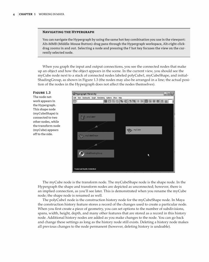
When you graph the input and output connections, you see the connected nodes that make up an object and how the object appears in the scene. In the current view, you should see the myCube node next to a stack of connected nodes labeled polyCube1, myCubeShape, and initial-ShadingGroup, as shown in Figure 1.3 (the nodes may also be arranged in a line; the actual posi-tion of the nodes in the Hypergraph does not affect the nodes themselves).
The myCube node is the transform node. The myCubeShape node is the shape node. In the Hypergraph the shape and transform nodes are depicted as unconnected; however, there is an implied connection, as you’ll see later. This is demonstrated when you rename the myCube node; the shape node is renamed as well.
The polyCube1 node is the construction history node for the myCubeShape node. In Maya the construction history feature stores a record of the changes used to create a particular node. When you first create a piece of geometry, you can set options to the number of subdivisions, spans, width, height, depth, and many other features that are stored as a record in this history node. Additional history nodes are added as you make changes to the node. You can go back and change these settings as long as the history node still exists. Deleting a history node makes all previous changes to the node permanent (however, deleting history is undoable).
Figure 1.3 The node net-work appears in the Hypergraph. This shape node (myCubeShape) is connected to two other nodes, while the transform node (myCube) appears off to the side.
92201c01.indd 4 3/9/09 11:06:44 AM
Maya nodes | 5
6. Keep the Hypergraph open, but select the cube in the viewport. Set the current menu to Polygons (you can change the menu set by choosing Polygons from the menu in the upper left of the Maya interface).
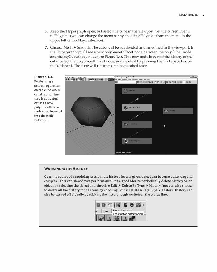
7. Choose Mesh Smooth. The cube will be subdivided and smoothed in the viewport. In the Hypergraph you’ll see a new polySmoothFace1 node between the polyCube1 node and the myCubeShape node (see Figure 1.4). This new node is part of the history of the cube. Select the polySmoothFace1 node, and delete it by pressing the Backspace key on the keyboard. The cube will return to its unsmoothed state.
Working with history
Over the course of a modeling session, the history for any given object can become quite long and complex. This can slow down performance. It’s a good idea to periodically delete history on an object by selecting the object and choosing Edit Delete By Type History. You can also choose to delete all the history in the scene by choosing Edit Delete All By Type History. History can also be turned off globally by clicking the history toggle switch on the status line.
Figure 1.4 Performing a smooth operation on the cube when construction his-tory is activated causes a new polySmoothFace node to be inserted into the node network.
92201c01.indd 5 3/9/09 11:06:44 AM
6 | Chapter 1 Working in Maya
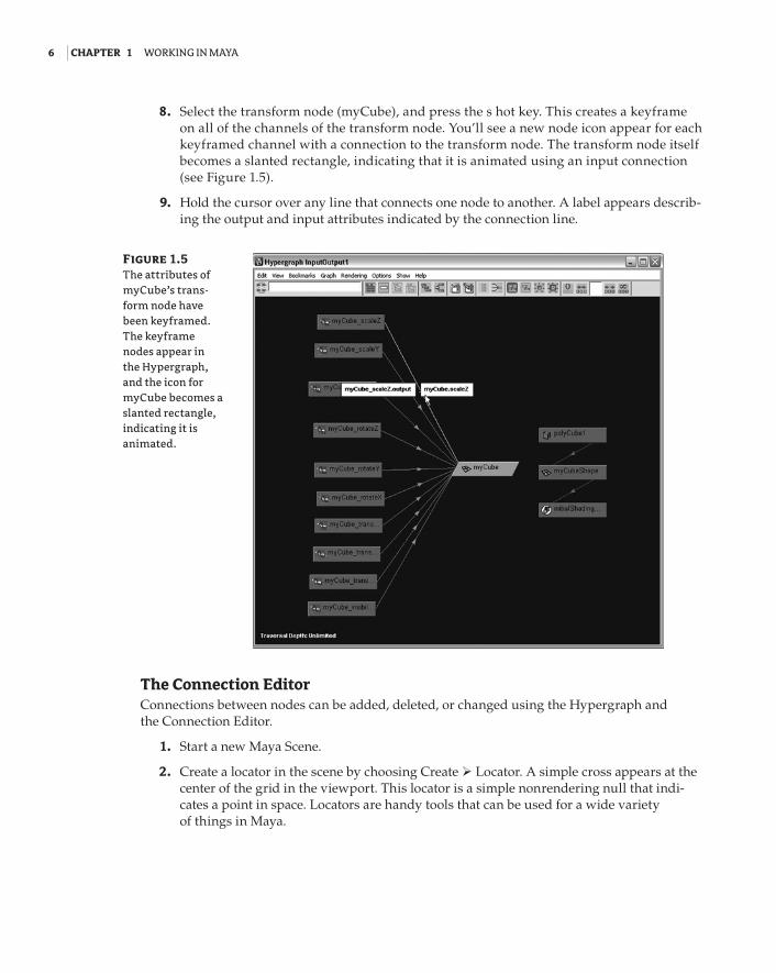
8. Select the transform node (myCube), and press the s hot key. This creates a keyframe on all of the channels of the transform node. You’ll see a new node icon appear for each keyframed channel with a connection to the transform node. The transform node itself becomes a slanted rectangle, indicating that it is animated using an input connection (see Figure 1.5).
9. Hold the cursor over any line that connects one node to another. A label appears describ-ing the output and input attributes indicated by the connection line.
The Connection EditorConnections between nodes can be added, deleted, or changed using the Hypergraph and the Connection Editor.
1. Start a new Maya Scene.
2. Create a locator in the scene by choosing Create Locator. A simple cross appears at the center of the grid in the viewport. This locator is a simple nonrendering null that indi-cates a point in space. Locators are handy tools that can be used for a wide variety of things in Maya.
Figure 1.5 The attributes of myCube’s trans-form node have been keyframed. The keyframe nodes appear in the Hypergraph, and the icon for myCube becomes a slanted rectangle, indicating it is animated.
92201c01.indd 6 3/9/09 11:06:45 AM
Maya nodes | 7
3. Press the w hot key to switch to the Move tool, select the locator at the center of the grid, and move it out of the way.
4. Press the g hot key to create another locator. The g hot key repeats the last action you per-formed, in this case the creation of the locator.
5. Create a NURBS (Non-Uniform Rational B-Splines) sphere in the viewport by choosing Create NURBS Primitives Sphere. If you have Interactive Creation selected, you’ll be prompted to drag on the grid in the viewport to create the sphere; otherwise, the sphere will be created at the center of the grid based on its default settings.
6. Move the sphere away from the center of the grid so you can clearly see both locators and the sphere. Use the Select tool (hot key = q) to drag a selection marquee around all three objects.
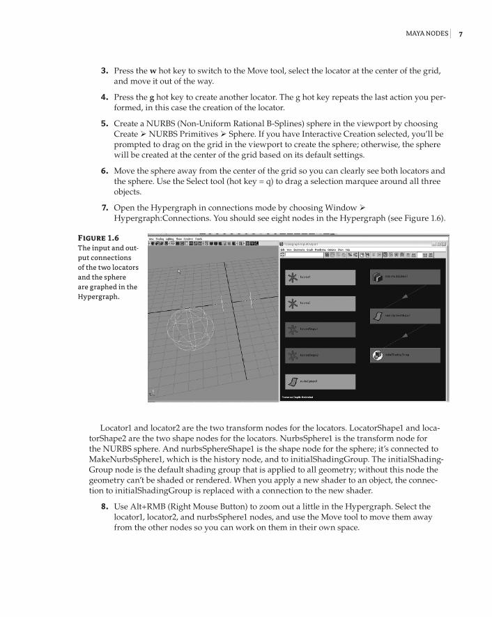
7. Open the Hypergraph in connections mode by choosing Window Hypergraph:Connections. You should see eight nodes in the Hypergraph (see Figure 1.6).
Locator1 and locator2 are the two transform nodes for the locators. LocatorShape1 and loca-torShape2 are the two shape nodes for the locators. NurbsSphere1 is the transform node for the NURBS sphere. And nurbsSphereShape1 is the shape node for the sphere; it’s connected to MakeNurbsSphere1, which is the history node, and to initialShadingGroup. The initialShading-Group node is the default shading group that is applied to all geometry; without this node the geometry can’t be shaded or rendered. When you apply a new shader to an object, the connec-tion to initialShadingGroup is replaced with a connection to the new shader.
8. Use Alt+RMB (Right Mouse Button) to zoom out a little in the Hypergraph. Select the locator1, locator2, and nurbsSphere1 nodes, and use the Move tool to move them away from the other nodes so you can work on them in their own space.
Figure 1.6 The input and out-put connections of the two locators and the sphere are graphed in the Hypergraph.
92201c01.indd 7 3/9/09 11:06:45 AM
8 | Chapter 1 Working in Maya
9. In the viewport, switch to wireframe mode. You can do this by pressing 4 on the key-board or clicking the wireframe icon on the icon bar at the top of the viewport window; the wireframe icon is the wireframe cube.
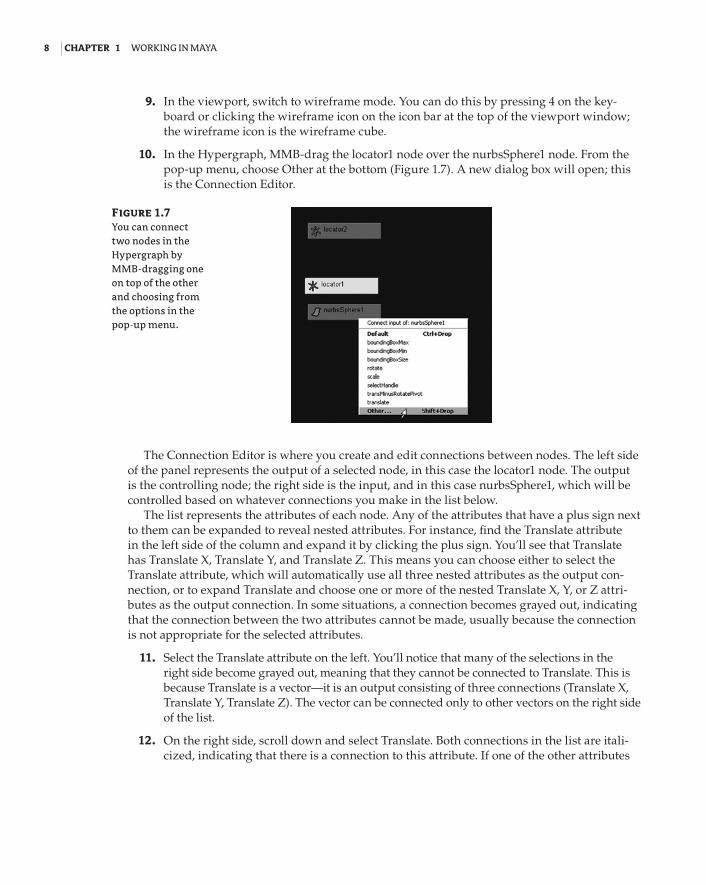
10. In the Hypergraph, MMB-drag the locator1 node over the nurbsSphere1 node. From the pop-up menu, choose Other at the bottom (Figure 1.7). A new dialog box will open; this is the Connection Editor.
The Connection Editor is where you create and edit connections between nodes. The left side of the panel represents the output of a selected node, in this case the locator1 node. The output is the controlling node; the right side is the input, and in this case nurbsSphere1, which will be controlled based on whatever connections you make in the list below.
The list represents the attributes of each node. Any of the attributes that have a plus sign next to them can be expanded to reveal nested attributes. For instance, find the Translate attribute in the left side of the column and expand it by clicking the plus sign. You’ll see that Translate has Translate X, Translate Y, and Translate Z. This means you can choose either to select the Translate attribute, which will automatically use all three nested attributes as the output con-nection, or to expand Translate and choose one or more of the nested Translate X, Y, or Z attri-butes as the output connection. In some situations, a connection becomes grayed out, indicating that the connection between the two attributes cannot be made, usually because the connection is not appropriate for the selected attributes.
11. Select the Translate attribute on the left. You’ll notice that many of the selections in the right side become grayed out, meaning that they cannot be connected to Translate. This is because Translate is a vector—it is an output consisting of three connections (Translate X, Translate Y, Translate Z). The vector can be connected only to other vectors on the right side of the list.
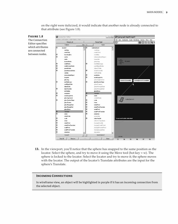
12. On the right side, scroll down and select Translate. Both connections in the list are itali-cized, indicating that there is a connection to this attribute. If one of the other attributes
Figure 1.7 You can connect two nodes in the Hypergraph by MMB-dragging one on top of the other and choosing from the options in the pop-up menu.
92201c01.indd 8 3/9/09 11:06:45 AM
Maya nodes | 9
on the right were italicized, it would indicate that another node is already connected to that attribute (see Figure 1.8).
13. In the viewport, you’ll notice that the sphere has snapped to the same position as the locator. Select the sphere, and try to move it using the Move tool (hot key = w). The sphere is locked to the locator. Select the locator and try to move it; the sphere moves with the locator. The output of the locator’s Translate attributes are the input for the sphere’s Translate.
Incoming Connections
In wireframe view, an object will be highlighted in purple if it has an incoming connection from the selected object.
Figure 1.8 The Connection Editor specifies which attributes are connected between nodes.
92201c01.indd 9 3/9/09 11:06:45 AM
10 | Chapter 1 Working in Maya
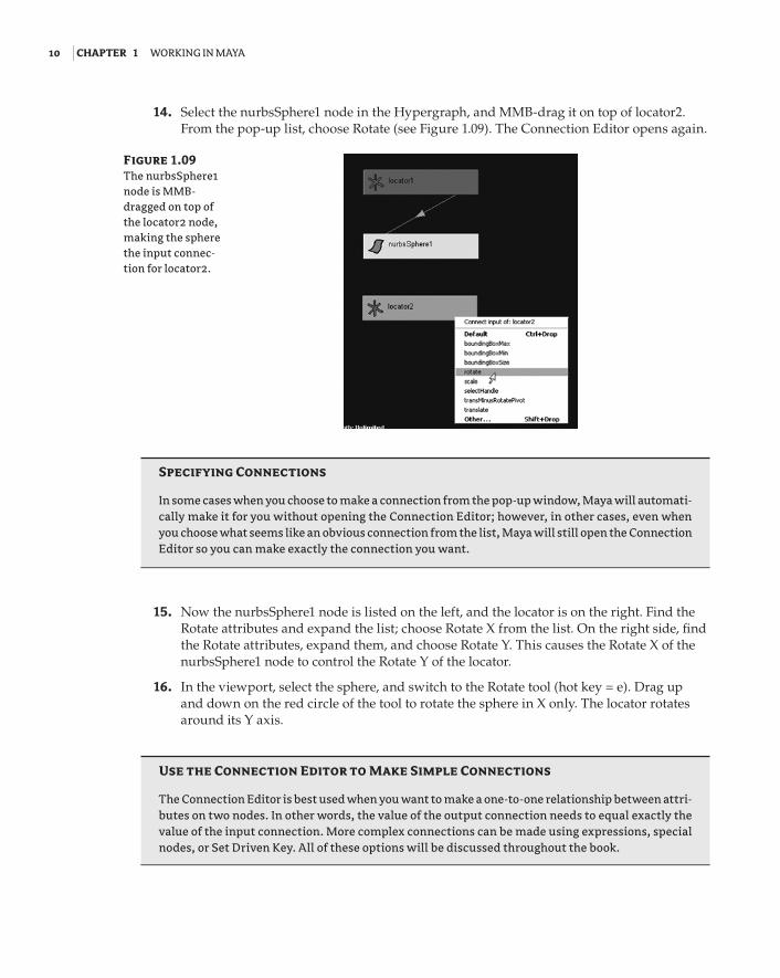
14. Select the nurbsSphere1 node in the Hypergraph, and MMB-drag it on top of locator2. From the pop-up list, choose Rotate (see Figure 1.09). The Connection Editor opens again.
Specifying Connections
In some cases when you choose to make a connection from the pop-up window, Maya will automati-cally make it for you without opening the Connection Editor; however, in other cases, even when you choose what seems like an obvious connection from the list, Maya will still open the Connection Editor so you can make exactly the connection you want.
15. Now the nurbsSphere1 node is listed on the left, and the locator is on the right. Find the Rotate attributes and expand the list; choose Rotate X from the list. On the right side, find the Rotate attributes, expand them, and choose Rotate Y. This causes the Rotate X of the nurbsSphere1 node to control the Rotate Y of the locator.
16. In the viewport, select the sphere, and switch to the Rotate tool (hot key = e). Drag up and down on the red circle of the tool to rotate the sphere in X only. The locator rotates around its Y axis.
Use the Connection editor to Make Simple Connections
The Connection Editor is best used when you want to make a one-to-one relationship between attri-butes on two nodes. In other words, the value of the output connection needs to equal exactly the value of the input connection. More complex connections can be made using expressions, special nodes, or Set Driven Key. All of these options will be discussed throughout the book.
Figure 1.09 The nurbsSphere1 node is MMB-dragged on top of the locator2 node, making the sphere the input connec-tion for locator2.
92201c01.indd 10 3/9/09 11:06:45 AM
Maya nodes | 11
17. You can break a connection by reselecting the connected node on either side of the Connection Editor so that the attribute is no longer highlighted. You can also select the connecting line in the Hypergraph and press the Delete key to break the connection.
Using the OutlinerThe Outliner is an alternative way to view the transform and shape nodes in a scene. The Outliner shows a hierarchical list of the nodes in the scene in a form similar to the outline of a book. The Outliner does not show the connections between nodes; rather it shows the hierarchy of the nodes in the scene. To see how this works try the following exercise:
1. Open the miniGun_v01.ma file from the Chapter1/scenes directory on the DVD. The scene consists of a minigun model in three parts.
2. Open the Outliner by Choosing Window Outliner.
Outliner Layout presets
The Outliner can be opened as a separate panel or, like many of the panels in Maya, it can be opened in a viewport. A popular window arrangement is to split the viewports into two views, with the left view set to the Outliner and the right view set to the perspective view. You can open this arrangement by going to the menu bar in a viewport window and choosing Panels Saved Layouts Persp/Outliner. You can also click the third layout button on the left side of the interface just below the toolbox.
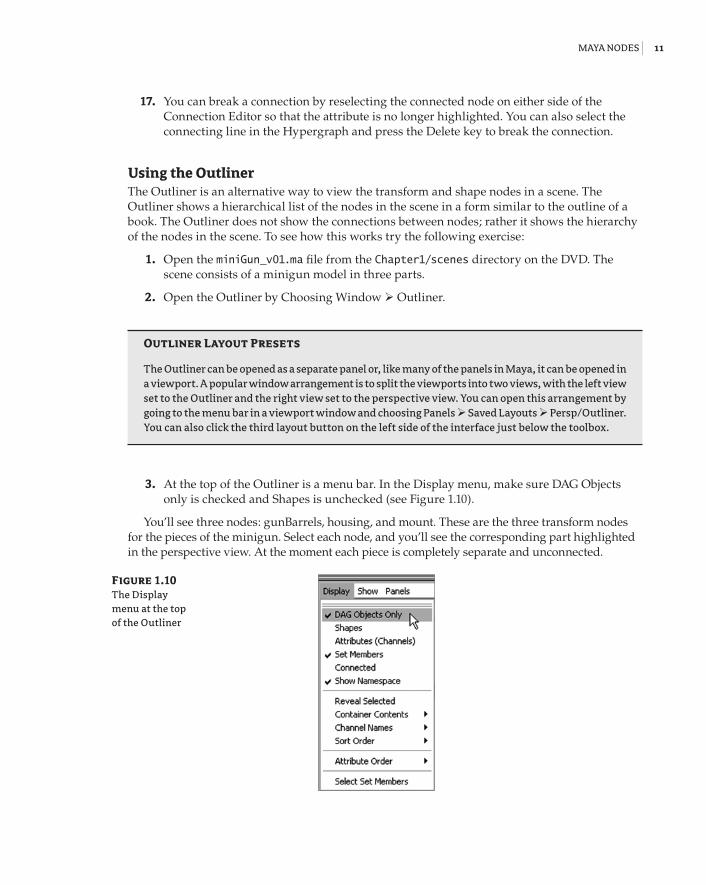
3. At the top of the Outliner is a menu bar. In the Display menu, make sure DAG Objects only is checked and Shapes is unchecked (see Figure 1.10).
You’ll see three nodes: gunBarrels, housing, and mount. These are the three transform nodes for the pieces of the minigun. Select each node, and you’ll see the corresponding part highlighted in the perspective view. At the moment each piece is completely separate and unconnected.
Figure 1.10 The Display menu at the top of the Outliner
92201c01.indd 11 3/9/09 11:06:45 AM
12 | Chapter 1 Working in Maya
4. Select the housing node and switch to the Rotate tool (hot key = e). Rotate the objects; nothing else is affected. Try moving housing (hot key = w); again, nothing else is affected.
5. Hit Undo a few times until the housing node returns to its original location and orientation.
6. In either the perspective view or the Outliner, select the gunBarrels object, and then Shift+click the housing object and choose Edit Parent.
Parenting one object to another means you have made one transform node the child of the second. When an object is a child node, it inherits its position, rotation, scale, and visibility from the parent node. In the Outliner, you’ll notice that the housing node has a plus sign beside it and the gunBarrels node is not visible. The plus sign indicates that the node has a child node.
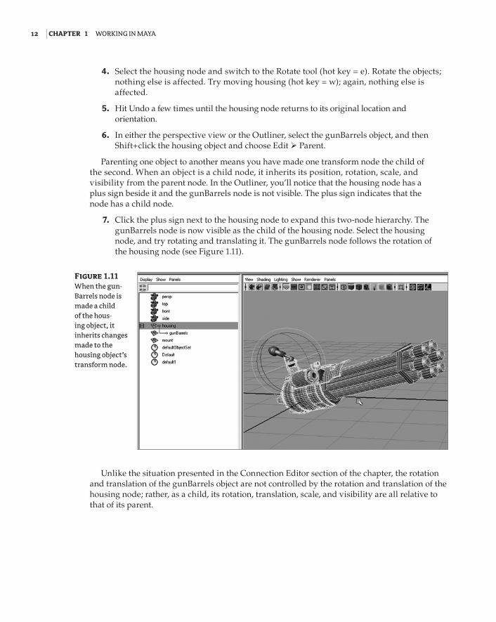
7. Click the plus sign next to the housing node to expand this two-node hierarchy. The gunBarrels node is now visible as the child of the housing node. Select the housing node, and try rotating and translating it. The gunBarrels node follows the rotation of the housing node (see Figure 1.11).
Unlike the situation presented in the Connection Editor section of the chapter, the rotation and translation of the gunBarrels object are not controlled by the rotation and translation of the housing node; rather, as a child, its rotation, translation, scale, and visibility are all relative to that of its parent.
Figure 1.11 When the gun-Barrels node is made a child of the hous-ing object, it inherits changes made to the housing object’s transform node.
92201c01.indd 12 3/9/09 11:06:45 AM
Maya nodes | 13
8. Select the gunBarrels node, and try rotating and translating the object; then rotate and translate the housing node. You’ll see the gun barrels maintain their position relative to the housing node. You could create an animation in which the gun barrels rotate on their own Z axis to spin around while firing, while the housing node is animated, rotating on all three axes in order to aim.
9. Hit Undo a few times (hot key = Ctrl+z) until both the housing and gunBarrel objects are back to their original position. In the Outliner, select the housing node, and MMB-drag it on top of the mount node. This is a way to quickly parent objects in the Outliner.
10. Click the plus signs next to the mount and housing nodes in the Outliner to expand the hierarchy. The lines indicate the organization of the hierarchy; the gun barrels are par-ented to the housing node, which is parented to the mount node.
Shift+click to expand the hierarchy
You can expand an entire hierarchy with one click in the Outliner. Just Shift+click the arrow for the hierarchy you want to expand.
11. In the Outliner, MMB-drag the gunBarrels node on top of the mount node. This rear-ranges the hierarchy so that now both the housing and gunBarrels nodes are children of the mount node. They are sibling nodes. Note the arrangement of the lines in the Outliner, indicating that the two nodes share the same parent.
12. Press Ctrl+z to undo the last action and return the gunBarrels node to its former place as a child of the housing node.
13. Select the mount node, and choose Edit Duplicate (hot key = Ctrl+d). This makes a copy of the entire hierarchy named mount1. Select the mount1 node, and switch to the Move tool (hot key = w). Pull on the red arrow of the tool to move the duplicate along the X axis about two units.
14. Select the mount node, and then Ctrl+click the mount1 node in the Outliner. Choose Edit Group (hot key = Ctrl+g) to group these two nodes under a single parent node.
A group node is a transform node that has no shape node. It’s just a location in space used to organize a hierarchy. Like a parent node, its children inherit its rotation, translation, scale, and visibility.
15. Select the group1 node and Shift+click the plus sign next to it in the Outliner to expand the group and all its children. Double-click the label for the group1 node in the Outliner to rename it; rename the group Guns.
92201c01.indd 13 3/9/09 11:06:45 AM
14 | Chapter 1 Working in Maya
renaming Nodes
You’ll notice that the duplicate mount node has been renamed mount1 automatically. Nodes on the same level of the hierarchy can’t have the same name. The child nodes do have the same name, and this is usually a bad idea. It can confuse Maya when more complex connections are made between nodes. Whenever you encounter this situation, you should take the time to rename the child nodes so that everything in the scene has a unique name.
16. Select the mount1 node in the Guns hierarchy, and choose Modify Prefix Hierarchy Names. In the pop-up window, type right_. This renames the top node and all its chil-dren so that “right_” precedes the name. Do the same with the other gun, but change the prefix to left_.
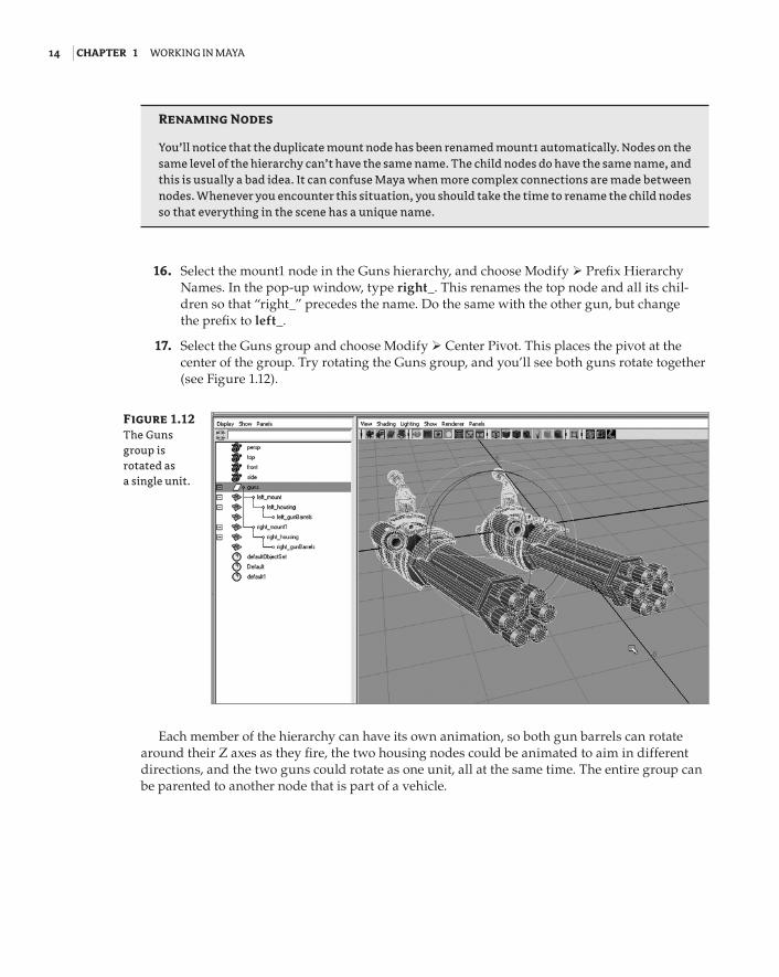
17. Select the Guns group and choose Modify Center Pivot. This places the pivot at the center of the group. Try rotating the Guns group, and you’ll see both guns rotate together (see Figure 1.12).
Each member of the hierarchy can have its own animation, so both gun barrels can rotate around their Z axes as they fire, the two housing nodes could be animated to aim in different directions, and the two guns could rotate as one unit, all at the same time. The entire group can be parented to another node that is part of a vehicle.
Figure 1.12 The Guns group is rotated as a single unit.
92201c01.indd 14 3/9/09 11:06:46 AM
Maya nodes | 15
Create a Classic Solar System Using hierarchies
A classic example of how parent-child relationships work in Maya is the solar system model. You can easily visualize how parenting works by creating simple sun, moon, and planet models and then parenting the models in such a way that the planets revolve around the sun and the moons revolve around the planets.
1. Create a simple NURBS sphere at the center of the grid.
2. Turn on Grid Snapping, and create a smaller sphere 10 units away from the center of the grid. This is your first planet.
3. Select the planet sphere, and choose the Move tool from the toolbox (hot key = w). Hold the d hot key to switch to the Pivot tool. The center of the icon for the Move tool changes to a circle when the Pivot tool is active.
4. While holding the d key, move the pivot point to the center of the sun; the planet should not move, just its pivot point. With Grid Snapping on, you should be able to snap the planet’s pivot to the center of the grid.
5. Try rotating the planet on its Y axis. You’ll see that it now rotates around the sun.
6. Undo changes to the planet’s rotation, and create a third sphere. Make it smaller than the planet; this will be the planet’s moon.
7. Place the moon sphere two units away from the planet. Using the d hot key, place the moon’s pivot point at the center of the planet. Grid Snapping should help you achieve this as long as the planet is snapped to the grid.
8. Parent the moon to the planet and the planet to the sun.
9. Create keyframes on the moon’s Y rotation and the planet’s Y rotation so that the planet revolves around the sun and the moon revolves around the planet.
You can expand an entire hierarchy with one click in the Outliner. Just Shift+click the arrow for the hierarchy you want to expand.
Display Options in the OutlinerThere are several options in the Outliner for displaying nodes and their hierarchical arrange-ments. You can see that the default perspective, top, side, and front cameras are visible as nodes at the top of the Outliner. Also there are a number of sets such as the defaultLightSet that appear at the bottom of the Outliner. These sets are mainly used for organization of data by Maya and are usually not directly edited or altered.
1. In the Display menu of the Outliner, check the Shapes option to display the shape nodes of the objects. The shape nodes appear parented to their respective transform node. You can select either the transform or the shape node in the Outliner to select the object.
92201c01.indd 15 3/9/09 11:06:46 AM
16 | Chapter 1 Working in Maya
accessing Outliner Options
You can right-click in the Outliner to quickly access the Outliner’s display options rather than use the menu at the top of the Outliner.
2. In the Display menu, activate the visibility of attributes by selecting the Attributes (Channels) option. Each node now has an expandable list of attributes. Most of the time you may want this option off because it clutters the Outliner and there are other ways to get to these attributes. Ultimately, how you use these options is up to you.
3. Turn off the Attributes display, and turn off the DAG Objects Only option.
4. To see a finished version of the scene, open miniGun_v02.ma from the chapter1\scenes directory on the DVD.
DAG stands for “Directed Acyclic Graph,” and DAG objects are those objects that have both a shape and transform node. It’s not really crucial to understand exactly what Directed Acyclic Graph means as long as you understand that it is an arrangement in which a shape node is par-ented to a transform node. When you turn off DAG Objects Only in the Outliner, you’ll see all of the nodes in the Maya scene appear. Many of these are default utility nodes required to make Maya function, such as the renderLayerManager node or the dynController1 node. Many other nodes appear when you create a new node or connection. An example of this would be a key-frame or an expression node.
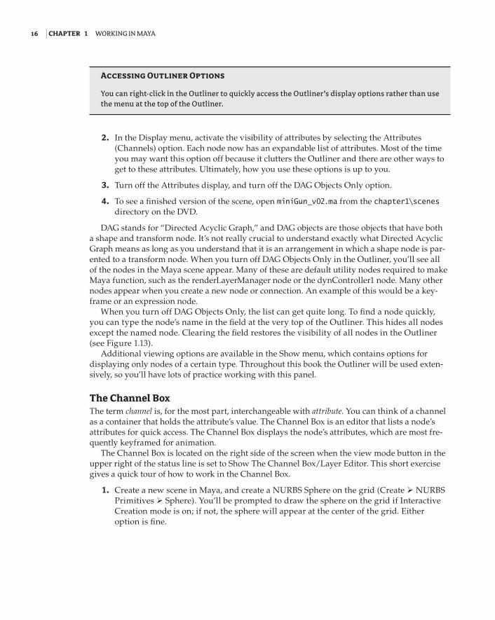
When you turn off DAG Objects Only, the list can get quite long. To find a node quickly, you can type the node’s name in the field at the very top of the Outliner. This hides all nodes except the named node. Clearing the field restores the visibility of all nodes in the Outliner (see Figure 1.13).
Additional viewing options are available in the Show menu, which contains options for displaying only nodes of a certain type. Throughout this book the Outliner will be used exten-sively, so you’ll have lots of practice working with this panel.
The Channel BoxThe term channel is, for the most part, interchangeable with attribute. You can think of a channel as a container that holds the attribute’s value. The Channel Box is an editor that lists a node’s attributes for quick access. The Channel Box displays the node’s attributes, which are most fre-quently keyframed for animation.
The Channel Box is located on the right side of the screen when the view mode button in the upper right of the status line is set to Show The Channel Box/Layer Editor. This short exercise gives a quick tour of how to work in the Channel Box.
1. Create a new scene in Maya, and create a NURBS Sphere on the grid (Create NURBS Primitives Sphere). You’ll be prompted to draw the sphere on the grid if Interactive Creation mode is on; if not, the sphere will appear at the center of the grid. Either option is fine.
92201c01.indd 16 3/9/09 11:06:46 AM
Maya nodes | 17
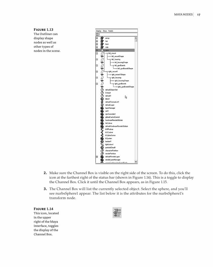
2. Make sure the Channel Box is visible on the right side of the screen. To do this, click the icon at the farthest right of the status bar (shown in Figure 1.14). This is a toggle to display the Channel Box. Click it until the Channel Box appears, as in Figure 1.15.
3. The Channel Box will list the currently selected object. Select the sphere, and you’ll see nurbsSphere1 appear. The list below it is the attributes for the nurbsSphere1’s transform node.
Figure 1.13 The Outliner can display shape nodes as well as other types of nodes in the scene.
Figure 1.14 This icon, located in the upper right of the Maya interface, toggles the display of the Channel Box.
92201c01.indd 17 3/9/09 11:06:46 AM
18 | Chapter 1 Working in Maya
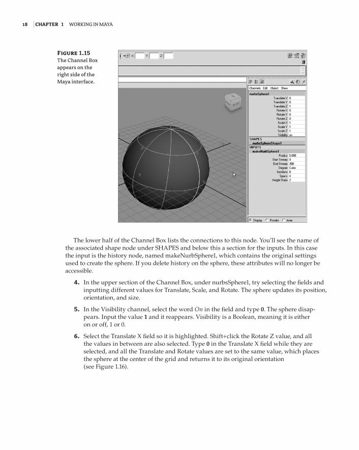
The lower half of the Channel Box lists the connections to this node. You’ll see the name of the associated shape node under SHAPES and below this a section for the inputs. In this case the input is the history node, named makeNurbSphere1, which contains the original settings used to create the sphere. If you delete history on the sphere, these attributes will no longer be accessible.
4. In the upper section of the Channel Box, under nurbsSphere1, try selecting the fields and inputting different values for Translate, Scale, and Rotate. The sphere updates its position, orientation, and size.
5. In the Visibility channel, select the word On in the field and type 0. The sphere disap-pears. Input the value 1 and it reappears. Visibility is a Boolean, meaning it is either on or off, 1 or 0.
6. Select the Translate X field so it is highlighted. Shift+click the Rotate Z value, and all the values in between are also selected. Type 0 in the Translate X field while they are selected, and all the Translate and Rotate values are set to the same value, which places the sphere at the center of the grid and returns it to its original orientation (see Figure 1.16).
Figure 1.15 The Channel Box appears on the right side of the Maya interface.
92201c01.indd 18 3/9/09 11:06:46 AM
Maya nodes | 19
7. In the makeNurbsSphere section, highlight the Start Sweep channel. Enter a value of 90, and the sphere opens up. You’re altering the construction history of the sphere so it is no longer a closed surface.
8. Select the word Sections so it is highlighted in black. MMB-drag in the viewport view back and forth. Doing this creates a virtual slider so you can change the value of the field interac-tively instead of numerically. This should work for all of the channels (most of the time).
9. Set the timeline to frame 1 and press the s hot key. You’ll see all of the channels turn orange, indicating that they have been keyframed. The s hot key keyframes all of the available channels.
10. Move the timeline to frame 24, and change some settings on both the transform node (the upper half of the Channel Box) and under makeNurbsSphere1. Press the s hot key again to set another key. Play the animation, and you’ll see the sphere update based on the key-framed changes.
The s hot key keyframes everything, even those channels you may not need to keyframe. You can use the Channel Box to keyframe specific channels.
11. Rewind the timeline, and choose Edit Keys Delete Keys to remove all of the keyframes on the sphere.
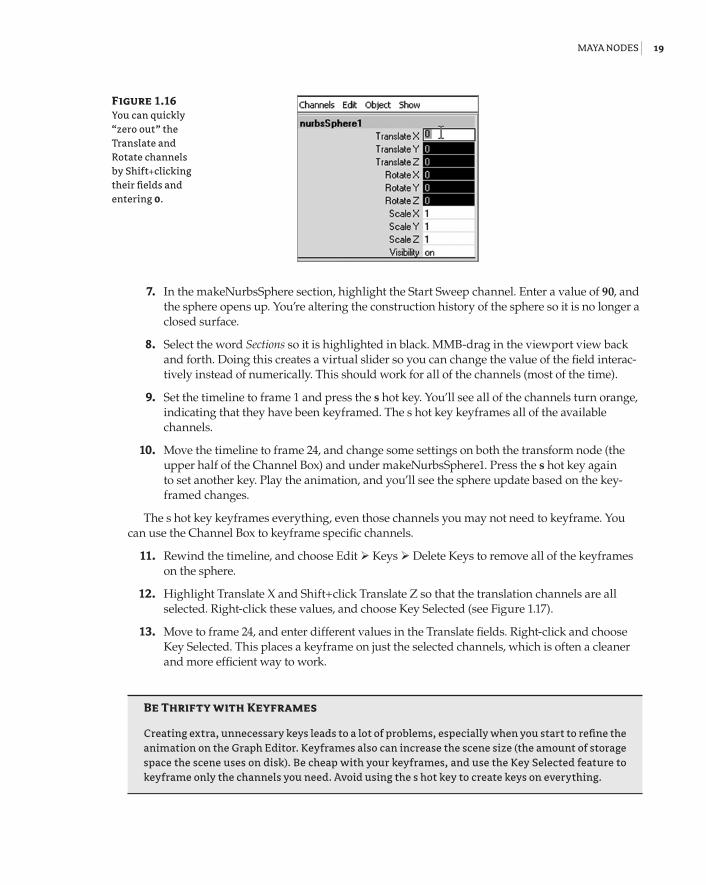
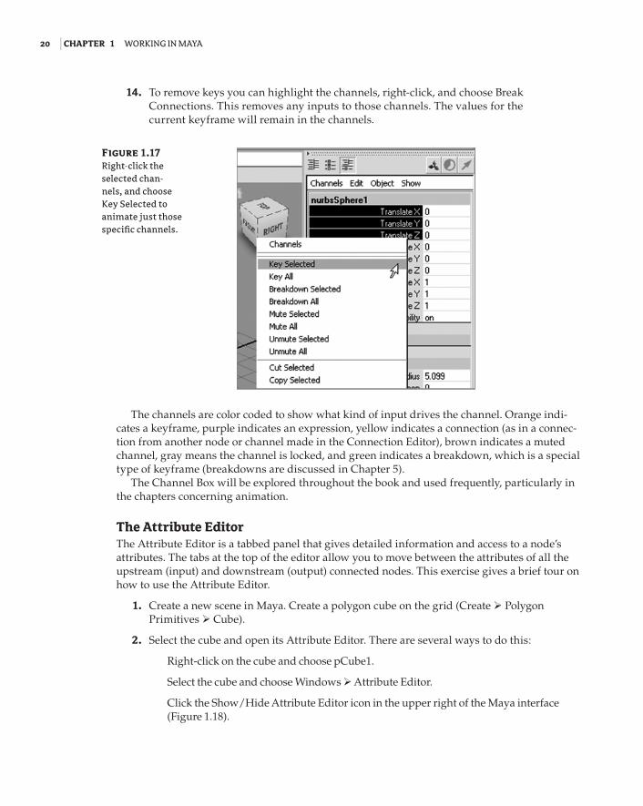
12. Highlight Translate X and Shift+click Translate Z so that the translation channels are all selected. Right-click these values, and choose Key Selected (see Figure 1.17).
13. Move to frame 24, and enter different values in the Translate fields. Right-click and choose Key Selected. This places a keyframe on just the selected channels, which is often a cleaner and more efficient way to work.
Be thrifty with Keyframes
Creating extra, unnecessary keys leads to a lot of problems, especially when you start to refine the animation on the Graph Editor. Keyframes also can increase the scene size (the amount of storage space the scene uses on disk). Be cheap with your keyframes, and use the Key Selected feature to keyframe only the channels you need. Avoid using the s hot key to create keys on everything.
Figure 1.16 You can quickly “zero out” the Translate and Rotate channels by Shift+clicking their fields and entering 0.
92201c01.indd 19 3/9/09 11:06:46 AM
20 | Chapter 1 Working in Maya
14. To remove keys you can highlight the channels, right-click, and choose Break Connections. This removes any inputs to those channels. The values for the current keyframe will remain in the channels.
The channels are color coded to show what kind of input drives the channel. Orange indi-cates a keyframe, purple indicates an expression, yellow indicates a connection (as in a connec-tion from another node or channel made in the Connection Editor), brown indicates a muted channel, gray means the channel is locked, and green indicates a breakdown, which is a special type of keyframe (breakdowns are discussed in Chapter 5).
The Channel Box will be explored throughout the book and used frequently, particularly in the chapters concerning animation.
The Attribute EditorThe Attribute Editor is a tabbed panel that gives detailed information and access to a node’s attributes. The tabs at the top of the editor allow you to move between the attributes of all the upstream (input) and downstream (output) connected nodes. This exercise gives a brief tour on how to use the Attribute Editor.
1. Create a new scene in Maya. Create a polygon cube on the grid (Create Polygon Primitives Cube).
2. Select the cube and open its Attribute Editor. There are several ways to do this:
Right-click on the cube and choose pCube1.
Select the cube and choose Windows Attribute Editor.
Click the Show/Hide Attribute Editor icon in the upper right of the Maya interface (Figure 1.18).
Figure 1.17 Right-click the selected chan-nels, and choose Key Selected to animate just those specific channels.
92201c01.indd 20 3/9/09 11:06:46 AM
Maya nodes | 21
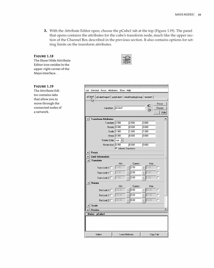
3. With the Attribute Editor open, choose the pCube1 tab at the top (Figure 1.19). The panel that opens contains the attributes for the cube’s transform node, much like the upper sec-tion of the Channel Box described in the previous section. It also contains options for set-ting limits on the transform attributes.
Figure 1.18 The Show/Hide Attribute Editor icon resides in the upper-right corner of the Maya interface.
Figure 1.19 The Attribute Edi-tor contains tabs that allow you to move through the connected nodes of a network.
92201c01.indd 21 3/9/09 11:06:47 AM
22 | Chapter 1 Working in Maya
Many of the settings can be accessed through the Attribute Editor’s rollout panels. These are collapsible sections of grouped settings.
4. In the Attribute Editor, under the pCube1 tab, click the triangle next to mental ray. This reveals mental ray–specific settings related to the cube. Note that there are subsections under mental ray that are also collapsible.
5. Choose the pCubeShape1 tab at the top of the Attribute Editor. This tab contains settings related to the shape node. For example, expand the Render Stats section, and you’ll see a list of settings that control how the shape will appear in a render.
6. Choose the polyCube1 tab, and you’ll see the construction history settings. If you delete history on the cube, this tab will no longer appear.
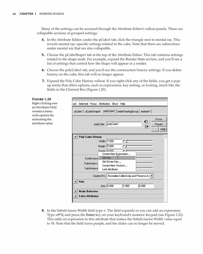
7. Expand the Poly Cube History rollout. If you right-click any of the fields, you get a pop-up menu that offers options, such as expressions, key setting, or locking, much like the fields in the Channel Box (Figure 1.20).
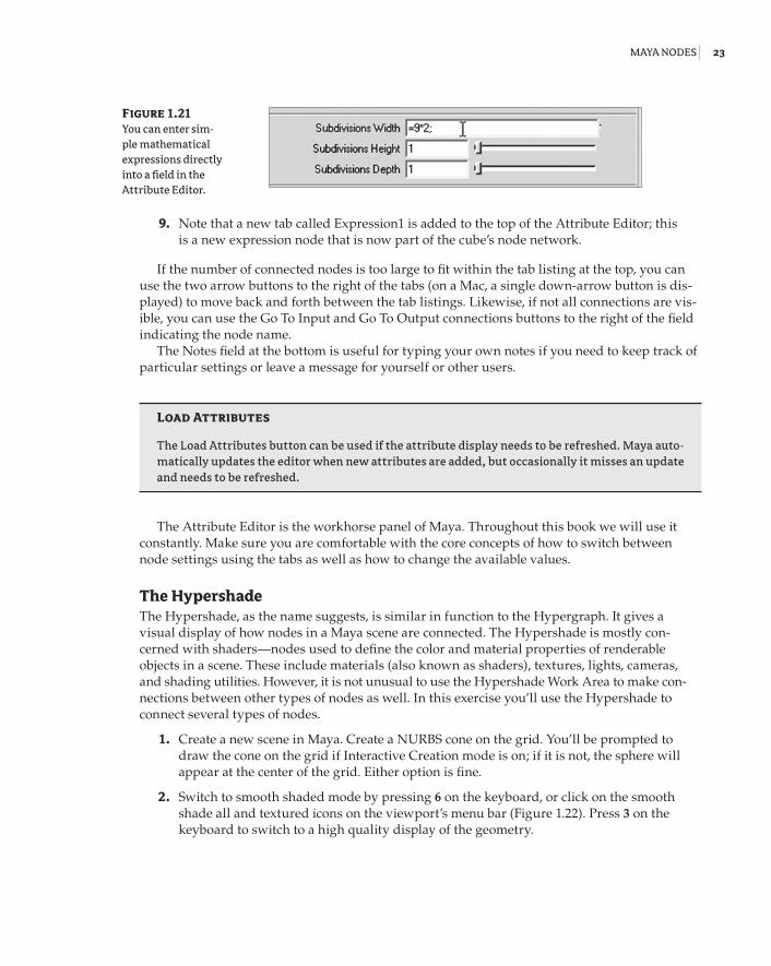
8. In the Subdivisions Width field type =. The field expands so you can add an expression. Type =9*2; and press the Enter key on your keyboard’s numeric keypad (see Figure 1.21). This adds an expression to this attribute that makes the Subdivisions Width value equal to 18. Note that the field turns purple, and the slider can no longer be moved.
Figure 1.20 Right-clicking over an Attribute Field reveals a menu with options for animating the attribute value.
92201c01.indd 22 3/9/09 11:06:47 AM
Maya nodes | 23
9. Note that a new tab called Expression1 is added to the top of the Attribute Editor; this is a new expression node that is now part of the cube’s node network.
If the number of connected nodes is too large to fit within the tab listing at the top, you can use the two arrow buttons to the right of the tabs (on a Mac, a single down-arrow button is dis-played) to move back and forth between the tab listings. Likewise, if not all connections are vis-ible, you can use the Go To Input and Go To Output connections buttons to the right of the field indicating the node name.
The Notes field at the bottom is useful for typing your own notes if you need to keep track of particular settings or leave a message for yourself or other users.
Load attributes
The Load Attributes button can be used if the attribute display needs to be refreshed. Maya auto-matically updates the editor when new attributes are added, but occasionally it misses an update and needs to be refreshed.
The Attribute Editor is the workhorse panel of Maya. Throughout this book we will use it constantly. Make sure you are comfortable with the core concepts of how to switch between node settings using the tabs as well as how to change the available values.
The HypershadeThe Hypershade, as the name suggests, is similar in function to the Hypergraph. It gives a visual display of how nodes in a Maya scene are connected. The Hypershade is mostly con-cerned with shaders—nodes used to define the color and material properties of renderable objects in a scene. These include materials (also known as shaders), textures, lights, cameras, and shading utilities. However, it is not unusual to use the Hypershade Work Area to make con-nections between other types of nodes as well. In this exercise you’ll use the Hypershade to connect several types of nodes.
1. Create a new scene in Maya. Create a NURBS cone on the grid. You’ll be prompted to draw the cone on the grid if Interactive Creation mode is on; if it is not, the sphere will appear at the center of the grid. Either option is fine.
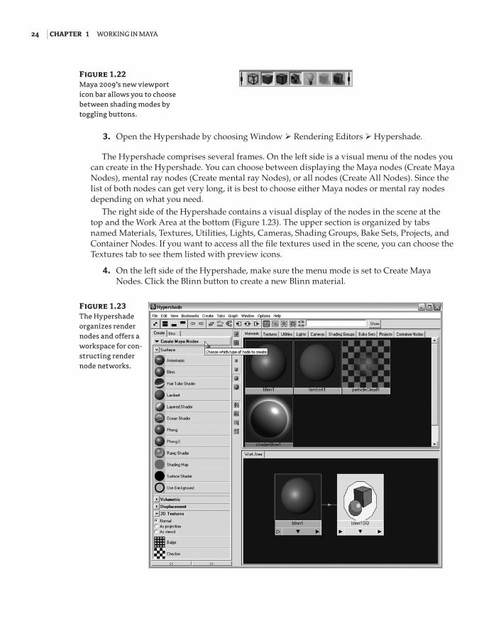
2. Switch to smooth shaded mode by pressing 6 on the keyboard, or click on the smooth shade all and textured icons on the viewport’s menu bar (Figure 1.22). Press 3 on the keyboard to switch to a high quality display of the geometry.
Figure 1.21 You can enter sim-ple mathematical expressions directly into a field in the Attribute Editor.
92201c01.indd 23 3/9/09 11:06:47 AM
24 | Chapter 1 Working in Maya
3. Open the Hypershade by choosing Window Rendering Editors Hypershade.
The Hypershade comprises several frames. On the left side is a visual menu of the nodes you can create in the Hypershade. You can choose between displaying the Maya nodes (Create Maya Nodes), mental ray nodes (Create mental ray Nodes), or all nodes (Create All Nodes). Since the list of both nodes can get very long, it is best to choose either Maya nodes or mental ray nodes depending on what you need.
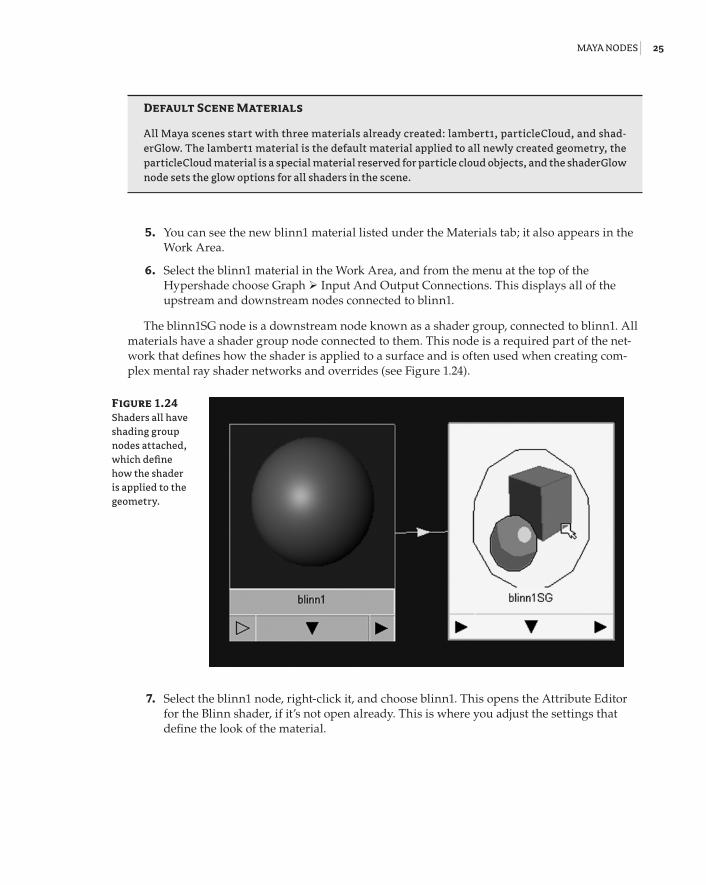
The right side of the Hypershade contains a visual display of the nodes in the scene at the top and the Work Area at the bottom (Figure 1.23). The upper section is organized by tabs named Materials, Textures, Utilities, Lights, Cameras, Shading Groups, Bake Sets, Projects, and Container Nodes. If you want to access all the file textures used in the scene, you can choose the Textures tab to see them listed with preview icons.
4. On the left side of the Hypershade, make sure the menu mode is set to Create Maya Nodes. Click the Blinn button to create a new Blinn material.
Figure 1.22 Maya 2009’s new viewport icon bar allows you to choose between shading modes by toggling buttons.
Figure 1.23 The Hypershade organizes render nodes and offers a workspace for con-structing render node networks.
92201c01.indd 24 3/9/09 11:06:47 AM
Maya nodes | 25
Default Scene Materials
All Maya scenes start with three materials already created: lambert1, particleCloud, and shad-erGlow. The lambert1 material is the default material applied to all newly created geometry, the particleCloud material is a special material reserved for particle cloud objects, and the shaderGlow node sets the glow options for all shaders in the scene.
5. You can see the new blinn1 material listed under the Materials tab; it also appears in the Work Area.
6. Select the blinn1 material in the Work Area, and from the menu at the top of the Hypershade choose Graph Input And Output Connections. This displays all of the upstream and downstream nodes connected to blinn1.
The blinn1SG node is a downstream node known as a shader group, connected to blinn1. All materials have a shader group node connected to them. This node is a required part of the net-work that defines how the shader is applied to a surface and is often used when creating com-plex mental ray shader networks and overrides (see Figure 1.24).
7. Select the blinn1 node, right-click it, and choose blinn1. This opens the Attribute Editor for the Blinn shader, if it’s not open already. This is where you adjust the settings that define the look of the material.
Figure 1.24 Shaders all have shading group nodes attached, which define how the shader is applied to the geometry.
92201c01.indd 25 3/9/09 11:06:48 AM
26 | Chapter 1 Working in Maya
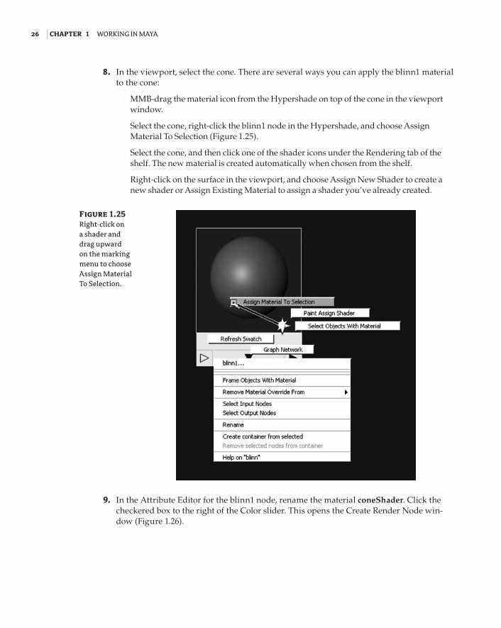
8. In the viewport, select the cone. There are several ways you can apply the blinn1 material to the cone:
MMB-drag the material icon from the Hypershade on top of the cone in the viewport window.
Select the cone, right-click the blinn1 node in the Hypershade, and choose Assign Material To Selection (Figure 1.25).
Select the cone, and then click one of the shader icons under the Rendering tab of the shelf. The new material is created automatically when chosen from the shelf.
Right-click on the surface in the viewport, and choose Assign New Shader to create a new shader or Assign Existing Material to assign a shader you’ve already created.
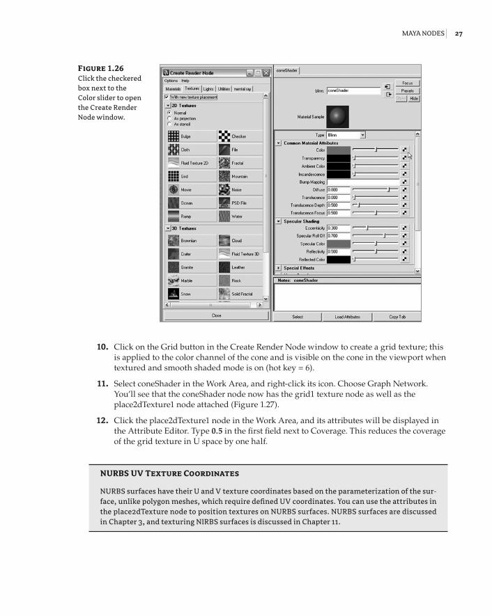
9. In the Attribute Editor for the blinn1 node, rename the material coneShader. Click the checkered box to the right of the Color slider. This opens the Create Render Node win-dow (Figure 1.26).
Figure 1.25 Right-click on a shader and drag upward on the marking menu to choose Assign Material To Selection.
92201c01.indd 26 3/9/09 11:06:48 AM
Maya nodes | 27
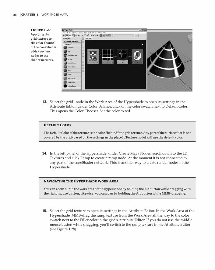
10. Click on the Grid button in the Create Render Node window to create a grid texture; this is applied to the color channel of the cone and is visible on the cone in the viewport when textured and smooth shaded mode is on (hot key = 6).
11. Select coneShader in the Work Area, and right-click its icon. Choose Graph Network. You’ll see that the coneShader node now has the grid1 texture node as well as the place2dTexture1 node attached (Figure 1.27).
12. Click the place2dTexture1 node in the Work Area, and its attributes will be displayed in the Attribute Editor. Type 0.5 in the first field next to Coverage. This reduces the coverage of the grid texture in U space by one half.
NUrBS UV texture Coordinates
NURBS surfaces have their U and V texture coordinates based on the parameterization of the sur-face, unlike polygon meshes, which require defined UV coordinates. You can use the attributes in the place2dTexture node to position textures on NURBS surfaces. NURBS surfaces are discussed in Chapter 3, and texturing NIRBS surfaces is discussed in Chapter 11.
Figure 1.26 Click the checkered box next to the Color slider to open the Create Render Node window.
92201c01.indd 27 3/9/09 11:06:48 AM
28 | Chapter 1 Working in Maya
13. Select the grid1 node in the Work Area of the Hypershade to open its settings in the Attribute Editor. Under Color Balance, click on the color swatch next to Default Color. This opens the Color Chooser. Set the color to red.
Default Color
The Default Color of the texture is the color “behind” the grid texture. Any part of the surface that is not covered by the grid (based on the settings in the place2dTexture node) will use the default color.
14. In the left panel of the Hypershade, under Create Maya Nodes, scroll down to the 2D Textures and click Ramp to create a ramp node. At the moment it is not connected to any part of the coneShader network. This is another way to create render nodes in the Hypershade.
Navigating the hypershade Work area
You can zoom out in the work area of the Hypershade by holding the Alt button while dragging with the right mouse button; likewise, you can pan by holding the Alt button while MMB-dragging.
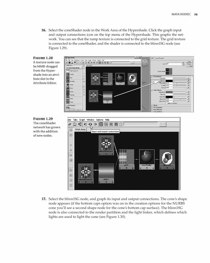
15. Select the grid texture to open its settings in the Attribute Editor. In the Work Area of the Hypershade, MMB-drag the ramp texture from the Work Area all the way to the color swatch next to the Filler color in the grid’s Attribute Editor. If you do not use the middle mouse button while dragging, you’ll switch to the ramp texture in the Attribute Editor (see Figure 1.28).
Figure 1.27 Applying the grid texture to the color channel of the coneShader adds two new nodes to the shader network.
92201c01.indd 28 3/9/09 11:06:48 AM
Maya nodes | 29
16. Select the coneShader node in the Work Area of the Hypershade. Click the graph input and output connections icon on the top menu of the Hypershade. This graphs the net-work. You can see that the ramp texture is connected to the grid texture. The grid texture is connected to the coneShader, and the shader is connected to the blinn1SG node (see Figure 1.29).
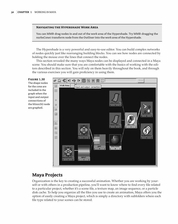
17. Select the blinn1SG node, and graph its input and output connections. The cone’s shape node appears (if the bottom caps option was on in the creation options for the NURBS cone you’ll see a second shape node for the cone’s bottom cap surface). The blinn1SG node is also connected to the render partition and the light linker, which defines which lights are used to light the cone (see Figure 1.30).
Figure 1.28 A texture node can be MMB-dragged from the Hyper-shade into an attri-bute slot in the Attribute Editor.
Figure 1.29 The coneShader network has grown with the addition of new nodes.
92201c01.indd 29 3/9/09 11:06:49 AM
30 | Chapter 1 Working in Maya
Navigating the hypershade Work area
You can MMB-drag nodes in and out of the work area of the Hypershade. Try MMB-dragging the nurbsCone1 transform node from the Outliner into the work area of the Hypershade.
The Hypershade is a very powerful and easy-to-use editor. You can build complex networks of nodes quickly just like rearranging building blocks. You can see how nodes are connected by holding the mouse over the lines that connect the nodes.
This section revealed the many ways Maya nodes can be displayed and connected in a Maya scene. You should make sure that you are comfortable with the basics of working with the edi-tors described in this section. You will rely on them heavily throughout the book, and through the various exercises you will gain proficiency in using them.
Maya ProjectsOrganization is the key to creating a successful animation. Whether you are working by your-self or with others in a production pipeline, you’ll want to know where to find every file related to a particular project, whether it’s a scene file, a texture map, an image sequence, or a particle disk cache. To help you organize all the files you use to create an animation, Maya offers you the option of easily creating a Maya project, which is simply a directory with subfolders where each file type related to your scenes can be stored.
Figure 1.30 The shape nodes for the cone are included in the graph when the input and output connections of the blinn1SG node are graphed.
92201c01.indd 30 3/9/09 11:06:49 AM
Maya Projects | 31
Create a New ProjectCreating a new project is very simple. Projects can be created on your local C drive, a secondary drive, or a network. The scene files used for each chapter in this book are stored in their own project directories on the DVD that comes with the book. Maya uses a default project directory when one has not been specified. This is located in your My Documents\maya\projects folder in Windows or Documents\maya\projects on a Mac. As an example you’ll create a Project direc-tory structure for the examples used in this chapter.
1. Start a new Maya 2009 session. You’ll note that an empty scene is created when you run Maya.
2. Choose File Project New.
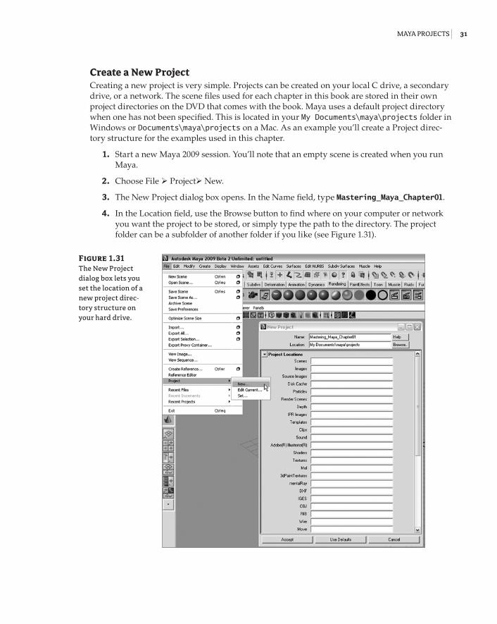
3. The New Project dialog box opens. In the Name field, type Mastering_Maya_Chapter01.
4. In the Location field, use the Browse button to find where on your computer or network you want the project to be stored, or simply type the path to the directory. The project folder can be a subfolder of another folder if you like (see Figure 1.31).
Figure 1.31 The New Project dialog box lets you set the location of a new project direc-tory structure on your hard drive.
92201c01.indd 31 3/9/09 11:06:49 AM
32 | Chapter 1 Working in Maya
In the Project Locations section, you’ll see a large number of labeled fields. The labels indi-cate the different types of files a Maya scene may or may not use. The fields indicate the path to the subdirectory where these types of files will be located.
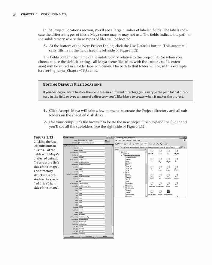
5. At the bottom of the New Project Dialog, click the Use Defaults button. This automati-cally fills in all the fields (see the left side of Figure 1.32).
The fields contain the name of the subdirectory relative to the project file. So when you choose to use the default settings, all Maya scene files (files with the .mb or .ma file exten-sion) will be stored in a folder labeled Scenes. The path to that folder will be, in this example, Mastering_Maya_Chapter01\Scenes.
editing Default File Locations
If you decide you want to store the scene files in a different directory, you can type the path to that direc-tory in the field or type a name of a directory you’d like Maya to create when it makes the project.
6. Click Accept. Maya will take a few moments to create the Project directory and all sub-folders on the specified disk drive.
7. Use your computer’s file browser to locate the new project; then expand the folder and you’ll see all the subfolders (see the right side of Figure 1.32).
Figure 1.32 Clicking the Use Defaults button fills in all of the fields with Maya’s preferred default file structure (left side of the image). The directory structure is cre-ated on the speci-fied drive (right side of the image).
92201c01.indd 32 3/9/09 11:06:49 AM
Maya Projects | 33
Edit and Change ProjectsYou may not need to use every folder Maya creates for you, or you may decide to change where Maya looks for elements, such as file textures. If you’re working on a number of different proj-ects, you may need to switch the current project. All of these options are available in the Maya File menu.
1. To edit the current Project, choose File Project Edit Current. The Edit Project window opens with all of the paths to the project subdirectories. You can type a new directory path into any one of these fields.
relinking Files after Changing project Settings
If you edit the project, Maya will look in the newly specified folders from this point on, but files used prior to editing the project will not be copied or moved. You’ll need to move these files using the computer’s file browser if you want Maya to easily find them after editing the project.
2. If you don’t want a particular directory to be created when you set up a project, leave the field blank.
3. To switch Projects, you can choose File Project Set, or choose a project listed in the Recent Projects menu.
recent project history
To change the number of projects listed in the Recent Projects menu, choose Window Settings/Preferences Preferences. In the Preferences dialog box, choose the Files/Projects listing from the Categories column, and increase or decrease the value in the Recent History Size For Projects field.
When working on a project with a number of other animators, you can choose to share the same project, which is a little risky, or each animator can create their own project directory structure within a shared folder. The latter example is a little safer as it prevents two people from having the same project open or overwriting each other’s work. Later on in the chapter you’ll learn how multiple animators can share parts of the scene using file references.
Overriding project Settings
You can choose to override a project setting for an individual scene element. For instance, by default, Maya looks to the source images directory for file textures. However, when you create a file texture node, you can use the Browse button to reference a file anywhere on your machine or the network. This is usually not a great idea; it defeats the purpose of organizing the files in the first place and can easily lead to broken links between the scene and the texture file. It’s a better idea to move all file textures used in the scene to the sourceimages directory or whatever directory is specified in your project settings.
92201c01.indd 33 3/9/09 11:06:49 AM
34 | Chapter 1 Working in Maya
AssetsA production pipeline consists of a number of artists with specialized tasks. Modelers, riggers, animators, lighting technical directors (TDs), and many others work together to create an anima-tion from a director’s vision. Organizing a complex animation sequence from all the nodes in a scene can be a daunting task. Maya 2009 introduces Assets, a workflow management tool designed to help a director separate the nodes in a scene and their many attributes into discrete interfaces so each team of specialized artists can concern itself only with its own part of the project.
ContainersAssets are created from containers. A container is a collection of nodes you choose to group together for the purpose of organization. A container is not the same as a group node; contain-ers do not have an associated transform node and do not appear in the viewport of a scene. For example, a model, its animation controls, and its shaders can all be placed in a single container. This example demonstrates some of the ways you can create and work with containers.
Containers versus Fluid Containers
Containers in this sense are not the same as Maya Fluid containers, which are a node related to fluid dynamics.
In this example you’ll create a container for the front wheels of a vehicle.
1. Open the vehicle_v01.ma file from the Chapter1\scenes directory on the DVD. You’ll see a three-wheeled vehicle. In the Outliner the vehicle is grouped.
2. Expand the vehicle group in the Outliner. The group consists of subgroups for the two front wheels, the rear wheel, the chassis, the suspension, and a NURBS curve named steering.
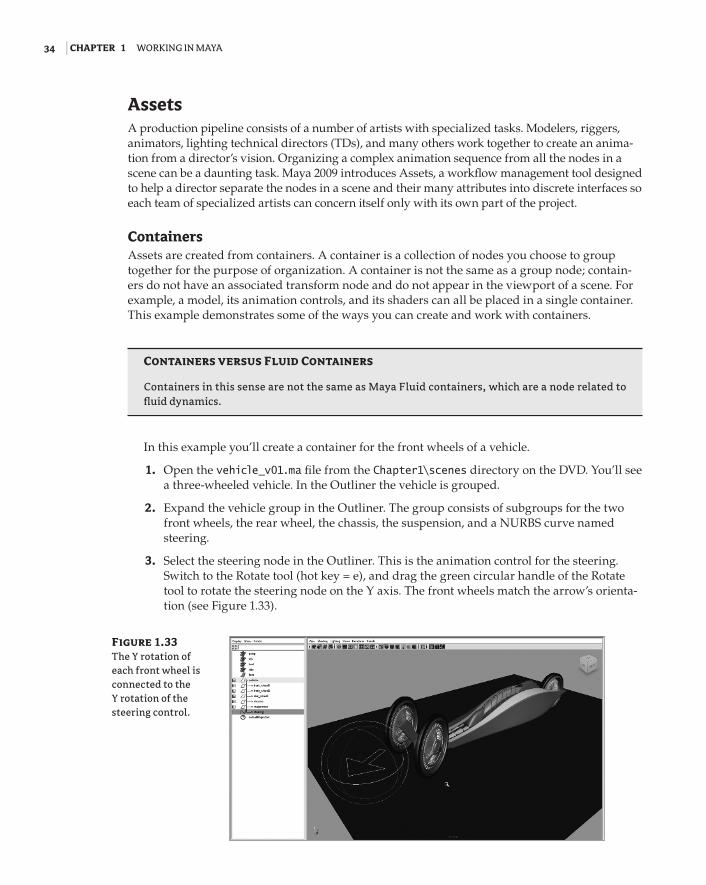
3. Select the steering node in the Outliner. This is the animation control for the steering. Switch to the Rotate tool (hot key = e), and drag the green circular handle of the Rotate tool to rotate the steering node on the Y axis. The front wheels match the arrow’s orienta-tion (see Figure 1.33).
Figure 1.33 The Y rotation of each front wheel is connected to the Y rotation of the steering control.
92201c01.indd 34 3/9/09 11:06:50 AM
assets | 35
If you select one of the front_wheel groups in the Outliner, you’ll see that its Rotate Y chan-nel is colored yellow, indicating it has an incoming connection. The steering curve’s Y rotation is connected to both front_wheel groups’ Y connection.
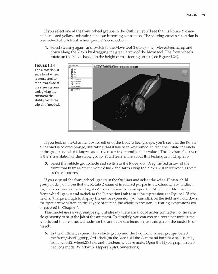
4. Select steering again, and switch to the Move tool (hot key = w). Move steering up and down along the Y axis by dragging the green arrow of the Move tool. The front wheels rotate on the X axis based on the height of the steering object (see Figure 1.34).
If you look in the Channel Box for either of the front_wheel groups, you’ll see that the Rotate X channel is colored orange, indicating that it has been keyframed. In fact, the Rotate channels of the group use what’s known as a driven key to determine their values. The keyframe’s driver is the Y translation of the arrow group. You’ll learn more about this technique in Chapter 5.
5. Select the vehicle group node and switch to the Move tool. Drag the red arrow of the Move tool to translate the vehicle back and forth along the X axis. All three wheels rotate as the car moves.
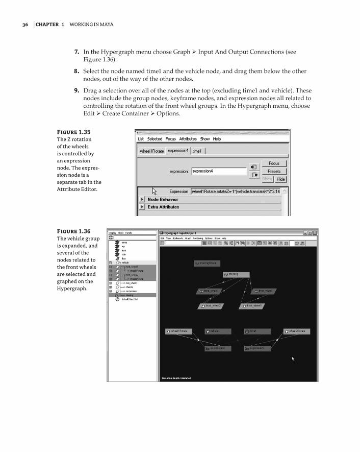
If you expand the front_wheel1 group in the Outliner and select the wheel1Rotate child group node, you’ll see that the Rotate Z channel is colored purple in the Channel Box, indicat-ing an expression is controlling its Z-axis rotation. You can open the Attribute Editor for the front_wheel1 group and switch to the Expression4 tab to see the expression; see Figure 1.35 (the field isn’t large enough to display the entire expression; you can click on the field and hold down the right-arrow button on the keyboard to read the whole expression). Creating expressions will be covered in Chapter 5.
This model uses a very simple rig, but already there are a lot of nodes connected to the vehi-cle geometry to help the job of the animator. To simplify, you can create a container for just the wheels and their connected nodes so the animator can focus on just this part of the model to do his job.
6. In the Outliner, expand the vehicle group and the two front_wheel groups. Select the front_wheel1 group, Ctrl+click (on the Mac hold the Command button) wheel1Rotate, front_wheel2, wheel2Rotate, and the steering curve node. Open the Hypergraph in con-nections mode (Window Hypergraph:Connections).
Figure 1.34 The X rotation of each front wheel is connected to the Y translate of the steering con-trol, giving the animator the ability to tilt the wheels if needed.
92201c01.indd 35 3/9/09 11:06:50 AM
36 | Chapter 1 Working in Maya
7. In the Hypergraph menu choose Graph Input And Output Connections (see Figure 1.36).
8. Select the node named time1 and the vehicle node, and drag them below the other nodes, out of the way of the other nodes.
9. Drag a selection over all of the nodes at the top (excluding time1 and vehicle). These nodes include the group nodes, keyframe nodes, and expression nodes all related to controlling the rotation of the front wheel groups. In the Hypergraph menu, choose Edit Create Container Options.
Figure 1.35 The Z rotation of the wheels is controlled by an expression node. The expres-sion node is a separate tab in the Attribute Editor.
Figure 1.36 The vehicle group is expanded, and several of the nodes related to the front wheels are selected and graphed on the Hypergraph.
92201c01.indd 36 3/9/09 11:06:50 AM
assets | 37
the Options Box
The small square to the right of a listing in the menu indicates the options. When you select just the listing in the menu, the action will be performed using the default settings. When you click the Options box to the right of the menu listing, a dialog box will open allowing you to change the options for the action. In this book, when you’re asked to choose options, it means you need to click the Options box to the right of the menu listing.
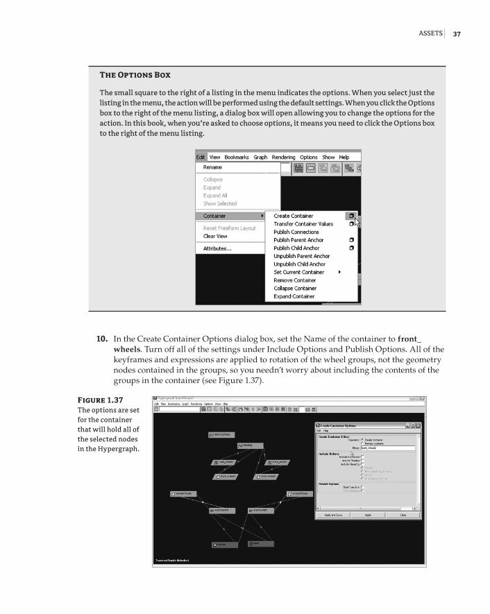
10. In the Create Container Options dialog box, set the Name of the container to front_wheels. Turn off all of the settings under Include Options and Publish Options. All of the keyframes and expressions are applied to rotation of the wheel groups, not the geometry nodes contained in the groups, so you needn’t worry about including the contents of the groups in the container (see Figure 1.37).
Figure 1.37 The options are set for the container that will hold all of the selected nodes in the Hypergraph.
92201c01.indd 37 3/9/09 11:06:50 AM
38 | Chapter 1 Working in Maya
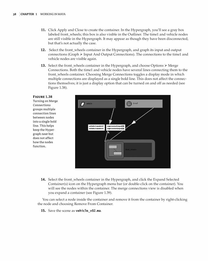
11. Click Apply and Close to create the container. In the Hypergraph, you’ll see a gray box labeled front_wheels; this box is also visible in the Outliner. The time1 and vehicle nodes are still visible in the Hypergraph. It may appear as though they have been disconnected, but that’s not actually the case.
12. Select the front_wheels container in the Hypergraph, and graph its input and output connections (Graph Input And Output Connections). The connections to the time1 and vehicle nodes are visible again.
13. Select the front_wheels container in the Hypergraph, and choose Options Merge Connections. Both the time1 and vehicle nodes have several lines connecting them to the front_wheels container. Choosing Merge Connections toggles a display mode in which multiple connections are displayed as a single bold line. This does not affect the connec-tions themselves; it is just a display option that can be turned on and off as needed (see Figure 1.38).
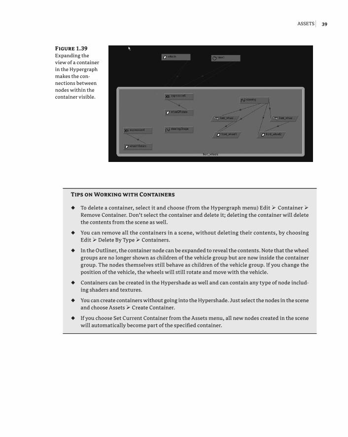
14. Select the front_wheels container in the Hypergraph, and click the Expand Selected Container(s) icon on the Hypergraph menu bar (or double-click on the container). You will see the nodes within the container. The merge connections view is disabled when you expand a container (see Figure 1.39).
You can select a node inside the container and remove it from the container by right-clicking the node and choosing Remove From Container.
15. Save the scene as vehicle_v02.ma.
Figure 1.38 Turning on Merge Connections groups multiple connection lines between nodes into a single bold line. This helps keep the Hyper-graph neat but does not affect how the nodes function.
92201c01.indd 38 3/9/09 11:06:51 AM
assets | 39
tips on Working with Containers
To delete a container, select it and choose (from the Hypergraph menu) Edit •u Container Remove Container. Don’t select the container and delete it; deleting the container will delete the contents from the scene as well.
You can remove all the containers in a scene, without deleting their contents, by choosing •u
Edit Delete By Type Containers.
In the Outliner, the container node can be expanded to reveal the contents. Note that the wheel •u
groups are no longer shown as children of the vehicle group but are now inside the container group. The nodes themselves still behave as children of the vehicle group. If you change the position of the vehicle, the wheels will still rotate and move with the vehicle.
Containers can be created in the Hypershade as well and can contain any type of node includ-•u
ing shaders and textures.
You can create containers without going into the Hypershade. Just select the nodes in the scene •u
and choose Assets Create Container.
If you choose Set Current Container from the Assets menu, all new nodes created in the scene •u
will automatically become part of the specified container.
Figure 1.39 Expanding the view of a container in the Hypergraph makes the con-nections between nodes within the container visible.
92201c01.indd 39 3/9/09 11:06:51 AM
40 | Chapter 1 Working in Maya
Creating Assets from ContainersYou create an asset by publishing selected attributes of the container’s nodes to the top level of the container. This means that the animator can select the container node and have all the cus-tom controls available in the Channel Box without having to hunt around the various nodes in the network. You can also template your container for use with similar animation rigs.
In this exercise you’ll create an asset based on the container created in the previous section.
1. Continue with the file from the previous section or open vehicle_v02.ma from the chapter1\scenes folder on the DVD.
2. In the Outliner, select the front_wheels container and expand the node by clicking the plus sign to the left of the node. Select the steering node from within the container.
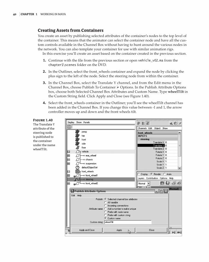
3. In the Channel Box, select the Translate Y channel, and from the Edit menu in the Channel Box, choose Publish To Container Options. In the Publish Attribute Options box, choose both Selected Channel Box Attributes and Custom Name. Type wheelTilt in the Custom String field. Click Apply and Close (see Figure 1.40).
4. Select the front_wheels container in the Outliner; you’ll see the wheelTilt channel has been added in the Channel Box. If you change this value between -1 and 1, the arrow controller moves up and down and the front wheels tilt.
Figure 1.40 The Translate Y attribute of the steering node is published to the container under the name wheelTilt.
92201c01.indd 40 3/9/09 11:06:51 AM
assets | 41
publish attributes from the attribute editor
If you need to publish a specific attribute that does not appear in the Channel Box, you can open the Attribute Editor for the appropriate node, right-click the attribute name, and choose the Publish options from the pop-up menu.
Using the Asset EditorThe Asset Editor can help you further customize and manage your scene’s assets.
1. Open the scene vehicle_v03.ma from the chapter1\scenes folder on the DVD.
2. In the Outliner you’ll see two containers: one for the wheels and another named carPaint, which holds the blue paint shader applied to the car.
3. To open the Asset Editor, choose Assets Asset Editor. The editor is in two panels; on the left side you’ll see all the assets in the scene.
The Asset Editor opens in view mode. You can click the plus sign in the square to see the nodes contained within each container. You can see the attributes of each node listed by clicking the plus sign in the circle next to each node.
4. Select the front_wheels container, and click the push pin icon above and to the right of the asset list to switch to edit mode. On the right-hand side of the editor, you’ll see the wheelTilt attribute we created in the previous section.
5. Select the arrow next to wheelTilt on the right-hand panel, and the wheels container expands to reveal the Translate channel of the steering node. This is the attribute origi-nally published to the container as wheelTilt.
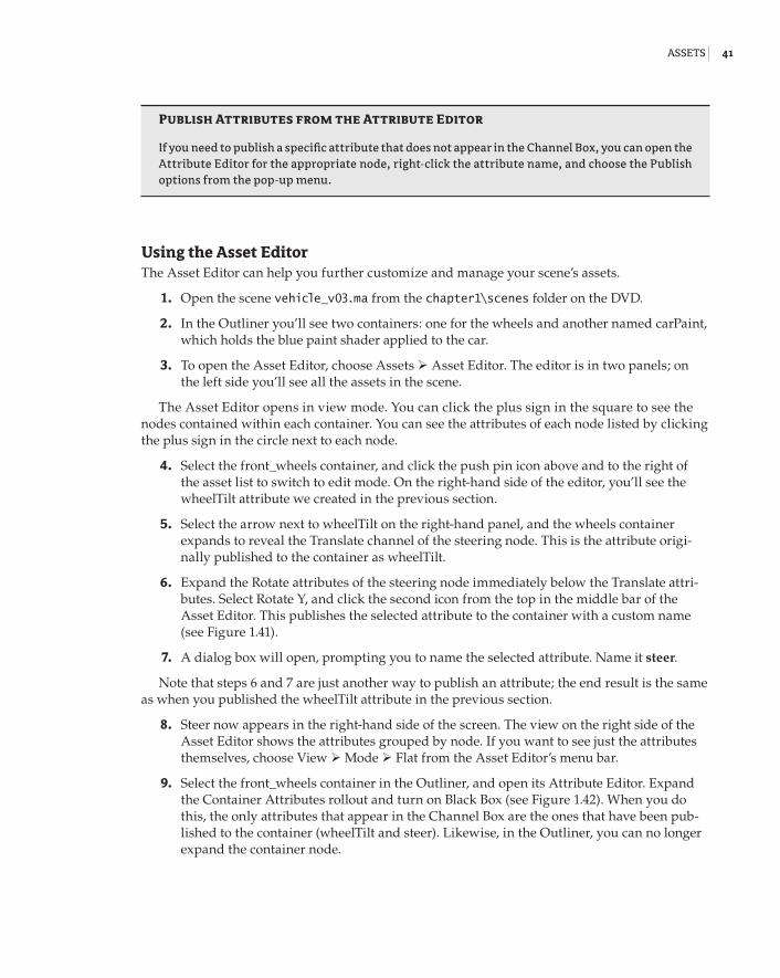
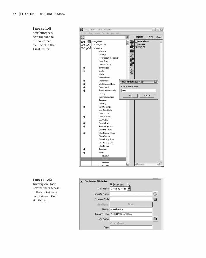
6. Expand the Rotate attributes of the steering node immediately below the Translate attri-butes. Select Rotate Y, and click the second icon from the top in the middle bar of the Asset Editor. This publishes the selected attribute to the container with a custom name (see Figure 1.41).
7. A dialog box will open, prompting you to name the selected attribute. Name it steer.
Note that steps 6 and 7 are just another way to publish an attribute; the end result is the same as when you published the wheelTilt attribute in the previous section.
8. Steer now appears in the right-hand side of the screen. The view on the right side of the Asset Editor shows the attributes grouped by node. If you want to see just the attributes themselves, choose View Mode Flat from the Asset Editor’s menu bar.
9. Select the front_wheels container in the Outliner, and open its Attribute Editor. Expand the Container Attributes rollout and turn on Black Box (see Figure 1.42). When you do this, the only attributes that appear in the Channel Box are the ones that have been pub-lished to the container (wheelTilt and steer). Likewise, in the Outliner, you can no longer expand the container node.
92201c01.indd 41 3/9/09 11:06:51 AM
42 | Chapter 1 Working in Maya
Figure 1.41 Attributes can be published to the container from within the Asset Editor.
Figure 1.42 Turning on Black Box restricts access to the container’s contents and their attributes.
92201c01.indd 42 3/9/09 11:06:51 AM
assets | 43
Template ContainersIf you have a number of animation rigs that use a similar setup, you can template a container and its custom attributes and apply this container to similar node networks.
1. In the Asset Editor, click the push pin icon so you’re still in edit mode. Select the front_wheels container and choose Template Save as. Container templates are saved to the assets folder of the current project. Name the container wheelControl and save it.
2. Save your current version of the scene. Open the file vehicle_v04.ma from the chapter1\scenes folder on the DVD. This scene contains an identical version of the vehicle painted orange instead of blue.
3. In the Outliner, note that a container named front_wheels has been created; however, no attributes of the contained nodes have been published to the container.
4. Select the front_wheels container and open the Asset Editor (Assets Asset Editor). In the Asset Editor, select the front_wheels container, and click the push pin icon to switch to edit mode.
5. Choose Template Assign Assign New Template. From the File Browser dialog box choose the wheelControl.template file from the assets folder of the current project (this folder should open by default). A copy of the wheelControl.template file can be found in the chapter1\assets directory on the DVD.
6. In the Asset Editor you’ll see the wheelTilt and steer attributes you created in the previ-ous section; however, they are not bound to the wheels template, meaning they are not connected.
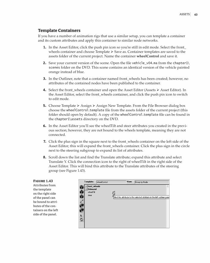
7. Click the plus sign in the square next to the front_wheels container on the left side of the Asset Editor; this will expand the front_wheels container. Click the plus sign in the circle next to the steering subgroup to expand its list of attributes.
8. Scroll down the list and find the Translate attribute; expand this attribute and select Translate Y. Click the connection icon to the right of wheelTilt in the right side of the Asset Editor. This will bind this attribute to the Translate attributes of the steering group (see Figure 1.43).
Figure 1.43 Attributes from the template on the right side of the panel can be bound to attri-butes of the con-tainers on the left side of the panel.
92201c01.indd 43 3/9/09 11:06:52 AM
44 | Chapter 1 Working in Maya
9. Expand the Rotate attributes below the Translate attributes, select the Rotate Y attribute on the left side of the editor, and click the connection icon to the right of steer to bind the attribute.
10. Close the Asset Editor, and select the front_wheels container in the Outliner. In the Channel Box the Wheel Tilt and Steer channels are now available. Change their values, and you’ll see the wheels on the car update.
This example is very simple; the usefulness of this workflow is much more obvious when working with complex node networks that have equally complex interfaces. You can create con-tainer interfaces at an early stage of the project as a way to keep artists organized.
File ReferencesFile referencing is another workflow tool that can be used when a team of artists is working on the same scene. For example, by using file references an animator can begin animating a scene while the modeler is still perfecting the model. This is also true for any of the other team mem-bers. A texture artist can work on textures for the same model at the same time. The animator and texture artist can import a reference of the model into their Maya scene, and each time the modeler saves a change, the model reference in the other scenes will update (when the animator and texture artist reload either the scene or the reference).
File referencing versus Importing
File referencing is not the same as importing a Maya scene into another Maya scene. When you import a Maya scene, all of the imported nodes become fully integrated into the new scene and have no links to any external files. On the other hand, file references maintain a link to external files regardless of whether the referenced files are open or closed. You can alter a referenced file in a scene, but it’s not a great idea; it can break the link to the referenced file and defeats the purpose of file referencing in the first place.
Referencing a FileIn this example you’ll reference a model into a scene, animate it, and then make changes to the original reference to get a basic idea of the file referencing workflow.
1. Find the vehicleReference_v01.ma scene and the street_v01.ma scene in the chapter1\scenes directory of the DVD. Copy both of these files to your local hard drive. Put them in the scenes directory of your current project.
2. Open the scene street_v01.ma from the scenes directory of the current project (or wher-ever you placed the file on your local drive). The scene contains a simple street model. A locator named carAnimation is attached to a curve in the center of the street. If you play the animation, you’ll see the locator zip along the curve.
92201c01.indd 44 3/9/09 11:06:52 AM
File reFerences | 45
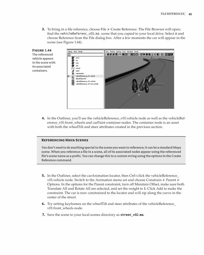
3. To bring in a file reference, choose File Create Reference. The File Browser will open; find the vehicleReferenc_v01.ma scene that you copied to your local drive. Select it and choose Reference from the File dialog box. After a few moments the car will appear in the scene (see Figure 1.44).
4. In the Outliner, you’ll see the vehicleReference_v01:vehicle node as well as the vehicleRef-erence_v01:front_wheels and carPaint container nodes. The container node is an asset with both the wheelTilt and steer attributes created in the previous section.
referencing Maya Scenes
You don’t need to do anything special to the scene you want to reference; it can be a standard Maya scene. When you reference a file in a scene, all of its associated nodes appear using the referenced file’s scene name as a prefix. You can change this to a custom string using the options in the Create Reference command.
5. In the Outliner, select the carAnimation locator, then Ctrl+click the vehicleReference_v01:vehicle node. Switch to the Animation menu set and choose Constrain Parent Options. In the options for the Parent constraint, turn off Maintain Offset, make sure both Translate All and Rotate All are selected, and set the weight to 1. Click Add to make the constraint. The car is now constrained to the locator and will zip along the curve in the center of the street.
6. Try setting keyframes on the wheelTilt and steer attributes of the vehicleReference_v01:front_wheels node.
7. Save the scene to your local scenes directory as street_v02.ma.
Figure 1.44 The referenced vehicle appears in the scene with its associated containers.
92201c01.indd 45 3/9/09 11:06:52 AM
46 | Chapter 1 Working in Maya
8. Open the vehicleReference_v01.ma scene from the directory where you copied this file on your local drive.
9. Expand the Vehicle group and the Chassis subgroup. Select the Body subgroup. Set its Scale Y attribute to 0.73 and its Scale Z attribute to 1.5.
10. Open the Hypershade (Window Rendering Editors Hypershade). Select the blue-Paint material. Click on the blue color swatch next to the Color channel, and use the Color Chooser to change the color to red.
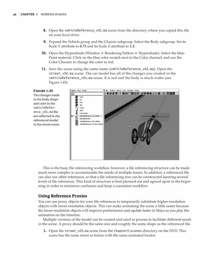
11. Save the scene using the same name (vehicleReference_v01.ma). Open the street_v02.ma scene. The car model has all of the changes you created in the vehicleReference_v01.ma scene. It is red and the body is much wider (see Figure 1.45).
This is the basic file referencing workflow; however, a file referencing structure can be made much more complex to accommodate the needs of multiple teams. In addition, a referenced file can also use other references, so that a file referencing tree can be constructed layering several levels of file references. This kind of structure is best planned out and agreed upon in the begin-ning in order to minimize confusion and keep a consistent workflow.
Using Reference ProxiesYou can use proxy objects for your file references to temporarily substitute higher-resolution objects with lower-resolution objects. This can make animating the scene a little easier because the lower-resolution objects will improve performance and update faster in Maya as you play the animation on the timeline.
Multiple versions of the model can be created and used as proxies to facilitate different needs in the scene. A proxy should be the same size and roughly the same shape as the referenced file.
1. Open the street_v03.ma scene from the chapter1\scenes directory on the DVD. This scene has the same street as before with the same animated locator.
Figure 1.45 The changes made to the body shape and color in the vehicleRefer-ence_v01.ma file are reflected in the referenced model in the street scene.
92201c01.indd 46 3/9/09 11:06:52 AM
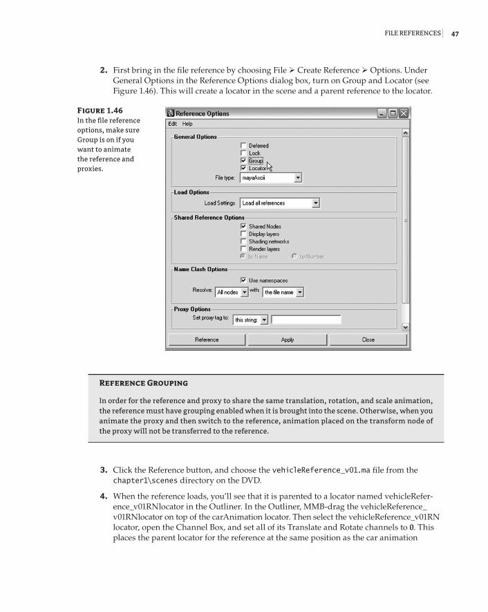
File reFerences | 47
2. First bring in the file reference by choosing File Create Reference Options. Under General Options in the Reference Options dialog box, turn on Group and Locator (see Figure 1.46). This will create a locator in the scene and a parent reference to the locator.
reference Grouping
In order for the reference and proxy to share the same translation, rotation, and scale animation, the reference must have grouping enabled when it is brought into the scene. Otherwise, when you animate the proxy and then switch to the reference, animation placed on the transform node of the proxy will not be transferred to the reference.
3. Click the Reference button, and choose the vehicleReference_v01.ma file from the chapter1\scenes directory on the DVD.
4. When the reference loads, you’ll see that it is parented to a locator named vehicleRefer-ence_v01RNlocator in the Outliner. In the Outliner, MMB-drag the vehicleReference_v01RNlocator on top of the carAnimation locator. Then select the vehicleReference_v01RN locator, open the Channel Box, and set all of its Translate and Rotate channels to 0. This places the parent locator for the reference at the same position as the car animation
Figure 1.46 In the file reference options, make sure Group is on if you want to animate the reference and proxies.
92201c01.indd 47 3/9/09 11:06:52 AM
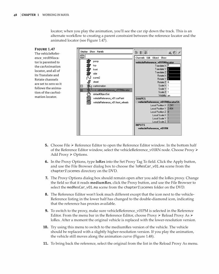
48 | Chapter 1 Working in Maya
locator; when you play the animation, you’ll see the car zip down the track. This is an alternate workflow to creating a parent constraint between the reference locator and the animated locator (see Figure 1.47).
5. Choose File Reference Editor to open the Reference Editor window. In the bottom half of the Reference Editor window, select the vehicleReference_v01RN node. Choose Proxy Add Proxy Options.
6. In the Proxy Options, type loRes into the Set Proxy Tag To field. Click the Apply button, and use the File Browser dialog box to choose the loResCar_v01.ma scene from the chapter1\scenes directory on the DVD.
7. The Proxy Options dialog box should remain open after you add the loRes proxy. Change the field so that it reads mediumRes, click the Proxy button, and use the File Browser to select the medResCar_v01.ma scene from the chapter1\scenes folder on the DVD.
8. The Reference Editor won’t look much different except that the icon next to the vehicle-Reference listing in the lower half has changed to the double-diamond icon, indicating that the reference has proxies available.
9. To switch to the proxy, make sure vehicleReference_v01PM is selected in the Reference Editor. From the menu bar in the Reference Editor, choose Proxy Reload Proxy As loRes. After a moment the original vehicle is replaced with the lower-resolution version.
10. Try using this menu to switch to the mediumRes version of the vehicle. The vehicle should be replaced with a slightly higher-resolution version. If you play the animation, the vehicle still moves along the animation curve (Figure 1.48).
11. To bring back the reference, select the original from the list in the Reload Proxy As menu.
Figure 1.47 The vehicleRefer-ence_v01RNloca-tor is parented to the carAnimation locator, and all of its Translate and Rotate channels are set to zero so it follows the anima-tion of the carAni-mation locator.
92201c01.indd 48 3/9/09 11:06:53 AM
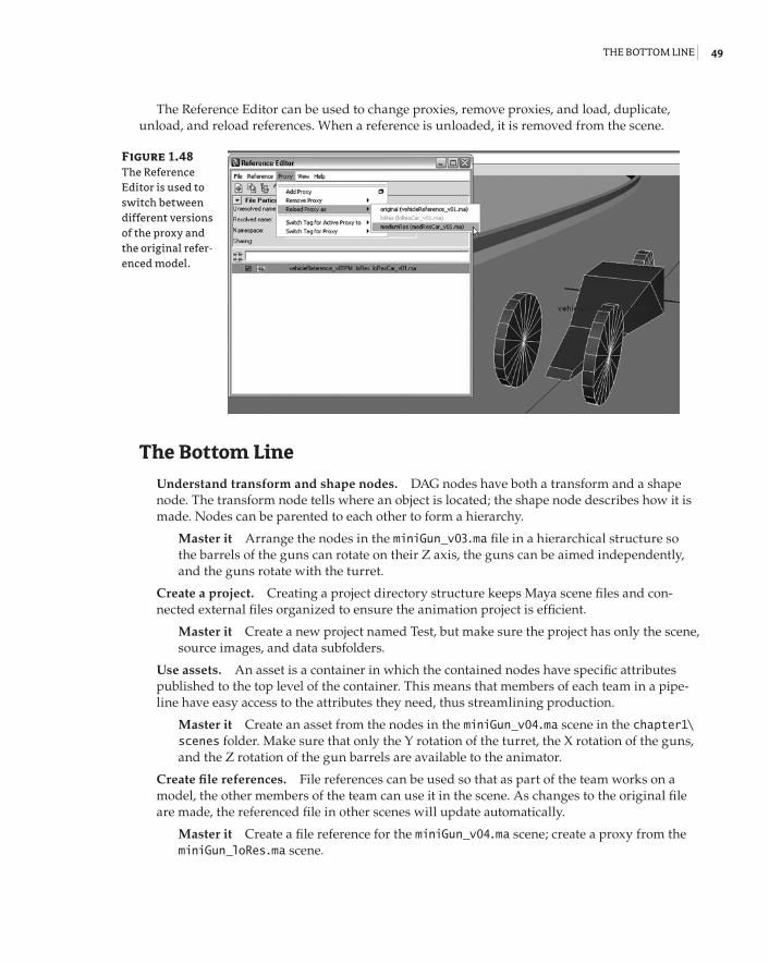
the BottoM line | 49
The Reference Editor can be used to change proxies, remove proxies, and load, duplicate, unload, and reload references. When a reference is unloaded, it is removed from the scene.
The Bottom Line
Understand transform and shape nodes. DAG nodes have both a transform and a shape node. The transform node tells where an object is located; the shape node describes how it is made. Nodes can be parented to each other to form a hierarchy.
Master it Arrange the nodes in the miniGun_v03.ma file in a hierarchical structure so the barrels of the guns can rotate on their Z axis, the guns can be aimed independently, and the guns rotate with the turret.
Create a project. Creating a project directory structure keeps Maya scene files and con-nected external files organized to ensure the animation project is efficient.
Master it Create a new project named Test, but make sure the project has only the scene, source images, and data subfolders.
Use assets. An asset is a container in which the contained nodes have specific attributes published to the top level of the container. This means that members of each team in a pipe-line have easy access to the attributes they need, thus streamlining production.
Master it Create an asset from the nodes in the miniGun_v04.ma scene in the chapter1\scenes folder. Make sure that only the Y rotation of the turret, the X rotation of the guns, and the Z rotation of the gun barrels are available to the animator.
Create file references. File references can be used so that as part of the team works on a model, the other members of the team can use it in the scene. As changes to the original file are made, the referenced file in other scenes will update automatically.
Master it Create a file reference for the miniGun_v04.ma scene; create a proxy from the miniGun_loRes.ma scene.
Figure 1.48 The Reference Editor is used to switch between different versions of the proxy and the original refer-enced model.
92201c01.indd 49 3/9/09 11:06:53 AM

92201c01.indd 50 3/9/09 11:06:53 AM