Embed Size (px)
Citation preview
Working ProjectDraft T10/1416-D
Revision 1728 January 2004
Information technology -SCSI Primary Commands - 3 (SPC-3)
This is an internal working document of T10, a Technical Committee of Accredited Standards Committee INCITS(InterNational Committee for Information Technology Standards). As such this is not a completed standard and hasnot been approved. The contents may be modified by the T10 Technical Committee. The contents are activelybeing modified by T10. This document is made available for review and comment only.
Permission is granted to members of INCITS, its technical committees, and their associated task groups toreproduce this document for the purposes of INCITS standardization activities without further permission, providedthis notice is included. All other rights are reserved. Any duplication of this document for commercial or for-profituse is strictly prohibited.
T10 Technical Editor: Ralph O. WeberENDL Texas18484 Preston RoadSuite 102 PMB 178Dallas, TX 75252USA
Telephone: 214-912-1373Facsimile: 972-596-2775Email: [email protected]
Reference numberISO/IEC 14776-313 : 200x
ANSI INCITS.***:200x
Printed Thursday, January 29, 2004 12:43 PM
Points of Contact:
T10 Chair T10 Vice-ChairJohn B. Lohmeyer George O. PenokieLSI Logic IBM4420 Arrows West Drive 3605 Highway 52 NColorado Springs, CO 80907-3444 MS: 2C6Tel: (719) 533-7560 Rochester, MN 55901Fax: (719) 533-7183 Tel: (507) 253-5208Email: [email protected] Fax: (507) 253-2880
Email: [email protected]
INCITS SecretariatINCITS Secretariat Telephone: 202-737-8888 1250 Eye Street, NW Suite 200 Facsimile: 202-638-4922 Washington, DC 20005 Email: [email protected]
T10 Web Site www.t10.org
T10 Reflector To subscribe send e-mail to [email protected] with ‘subscribe’ in message bodyTo unsubscribe send e-mail to [email protected] with ‘unsubscribe’ in message bodyInternet address for distribution via T10 reflector: [email protected]
Document DistributionINCITS Online Store http://www.techstreet.com/incits.htmlmanaged by Techstreet Telephone: 1-734-302-7801 or1327 Jones Drive 1-800-699-9277Ann Arbor, MI 48105 Facsimile: 1-734-302-7811
or
Global Engineering http://global.ihs.com/15 Inverness Way East Telephone: 1-303-792-2181 orEnglewood, CO 80112-5704 1-800-854-7179
Facsimile: 1-303-792-2192
28 January 2004 T10/1416-D Revision 17
Revision Information
Changes in the SCSI standards family list, clause 1, are never marked with change bars. Changes in theASC/ASCQ, Operation Code, Log Page Code, Mode Page Code and Vendor ID tables are never marked withchange bars.
1 Approved Documents Included
The following T10 approved proposals have been incorporated SPC-3 up to and including this revision:
99-148r7 Proposed Addition of Read and Write Attribute Commands to SPC-200-232r9 Asymmetric SCSI behavior00-257r3 Expander Communication Protocol00-344r0 Identifying a 3rd Party Copy Management Device/Lun00-359r8 Unit Attention Issue00-396r2 Mode pages equivalents for ECP commands00-398r3 EXTENDED COPY: IPv4 Target Descriptor00-425r4 Long Identifiers in SPC-3, SAM-2, SBC-2 and other XOR issues01-004r2 SPC-3 Logical unit groups01-025r0 SPC-2 FIRST BURST SIZE definition01-027r2 Numeric Media Serial Number01-065r2 SPC-3 VPD Page 83 Device Identifier rewrite01-068r6 Definition of Well Known Logical Units01-099r6 SPC-3 Letting persistent reservations ignore target ports01-100r4 Specify initiator ports for persistent reservation registrations01-104r0 SRP Protocol Identifiers [Annex C table for T10 IEEE OUI Binary Identifiers]01-134r1 SAM-2, SPC-3, SPI-4, SBC-2 WAKEUP and reset cleanup01-174r2 Public comment on target descriptors in SPC-2 (SBP-2/3 EXTENDED COPY target descriptor)01-182r1 SAM-2 device and port names01-185r1 SAM-2 layering terminology proposal01-192r2 SPC-3 Extended Copy target descriptor for SRP01-193r1 SRP Alias entry designation formats01-199r3 SPC-3 SBC-2 SSC-2 sense data changes01-204r2 Proposal for an additional persistent Reservations type in SPC-301-247r1 SPC-3 Informational exceptions log page01-253r3 Report Supported Operation Codes Command01-267r3 Interlocking for exceptions - BUSY, RESERVATION CONFLICT and TASK SET FULL01-268r3 Access Controls for SPC-3 (the rewrite)01-269r0 Sense Codes for delivery subsystem errors that have to be reported with SCSI status01-305r0 Proposed change to UA requirement on SET DEVICE IDENTIFIER command01-316r1 Proposed change to SSC-2 Progress Indication [ASC/ASCQ definitions only]01-318r1 SAM-2 SPC-3 Eliminate SCSI-2 references and describe CA02-016r1 SPC-3 TST field description02-017r0 SPC-3 sense data size limit02-025r0 SPC-3 Unit Attention interlock and Asynchronous Event Reporting02-026r1 SPC-3 REQUEST SENSE during pending-enrolled state02-029 Minutes of T10 Meeting #47 — Assign ASC/ASCQ 14h/07h to LOCATE OPERATION FAILURE02-035r3 MD5 Logical Unit Identifier02-065r2 SPC-3 Persistent reservations corrections02-075r1 EUI-48 software interface ID VPD page02-102 Minutes of T10 Meeting #48 — Assign a new device type code to the ADI command set02-108r0 Obsolete Reserve/Release in SPC-302-115r0 SPC-3 table 230 incorrect
Working Draft SCSI Primary Commands - 3 (SPC-3) #
T10/1416-D Revision 17 28 January 2004
02-134r2 Clearing effects of I_T nexus loss {w/ no mode page changes}02-144r0 SPC-3 Informational exceptions, linked commands, and CONDITION MET02-145r0 SPC-3 AERC clarification02-149r1 SPC-3 Port-specific mode page clarifications02-189r1 SES-2 SPC-3 vendor-specific diagnostic pages02-190r0 SES-2 Enclosure busy indication02-194r1 SES-2 Protocol-specific device element information02-160 Minutes of CAP WG — Remove proposed DEVICE LOCKS operation code assignment02-232r2 SAM-3 SPC-3 SBC-2 SSC-2 Clearing effects of I_T nexus loss02-246r1 SPC-3 protocol-specific changes for SAS SSP02-254r5 WWNs for WLUNs02-260r1 Mandatory REPORT LUNS Support02-286r1 Extended Copy Write filemarks operation Segment Descriptor Immediate Bit02-303r1 Inquiry Command Parameter Length Increase02-304r1 Allowing TUR Through Persistent Reservations02-308r1 Change ASC for truncated parameter in SPC-3 for LOG SELECT command02-346r1 Report Supported Task Management Functions02-403r2 Maximum and first burst size and protocol services02-404r2 Sense Data Length for Execute Command02-419r7 Device Identifiers and VPD Data02-449r3 SAS Simple Relative Offset02-454r0 SPC-3 Add NAA=2 format to VPD 8302-464r3 SAM-3, SPC-3, and SBC power conditions proposal02-466r0 SAM-3 definitions for SCSI initiator device and SCSI target device02-485r1 READ MEDIA SERIAL NUMBER command02-488r1 SAM-3 Logical Unit Names03-001r1 Remove TARGET RESET from SAM-3 and SPC-303-002r3 Remove SPI from SAM-3 and SPC-303-005r1 What is architectural about SAM-3 CDB definitions?03-028r2 Block Limits VPD page03-031r0 Obsolete Medium Partition mode pages 2-403-051r0 Remove AEN from SPC-303-060r1 Vendor Identification Assignment03-088r0 Rename some SAS additional sense codes03-092r1 Other SPC-3 Fixes03-094r3 Yet More Persistent Reservation Fixes03-127r1 SPC-3 MSB and LSB labels03-164r3 SAS: Initiator Response Timeout timer (ASC/ASCQ definition only)03-169r1 SPC-3: Un-hiding S.M.A.R.T.03-172r1 QErr=01b & CHECK CONDITION Initiator03-183r6 New Inquiry VPD Page - Management Network Address03-203r1 TransportID Cleanup03-209r0 Limiting the MD5 logical unit identifier to logical units03-210r4 PERSISTENT RESERVE OUT SPEC_I_PT additional parameter data03-227r1 Add additional sense code values to SPC-3 for ADC03-230r3 Persistent All Registrants Fix03-232r5 Proposal for Modified Reservation Handling03-243r2 Optional INQUIRY command processing before entering task set03-253r0 Persistent All Registrants Fix Part 203-254r0 Obsolete the Control mode page Disable Queueing bit03-257r0 Queue Algorithm Modifier default value03-271r2 Obsolete untagged tasks03-287r0 New additional sense code for NOTIFY (ENABLE SPINUP) REQUIRED03-299r0 Additional Sense Codes requests for OSD r08
xvi Working Draft SCSI Primary Commands - 3 (SPC-3)
28 January 2004 T10/1416-D Revision 17
03-303r0 ADT Protocol Identifier03-316r3 Mode Page Policy VPD page03-335r1 Obsolete block device linked commands03-343r1 Report supported asymmetric access states03-350r0 Changing Control mode page with commands in the task set03-351r2 Reporting task attribute support03-356r0 Protocol Identifier for ATAPI03-359r1 Disable implicit asymmetric access03-365r1 End-to-End Data Protection04-007r0 Generation codes for Help Text and String pages (add new page codes)04-016r2 Obsolete Third Party XOR Commands04-022r1 Additional Sense Code requests for OSD r0904-025r0 Power Conditions Clarifications04-043r0 New ASC/ASCQ for ESI data validation checksum error04-044r0 OSD Error Handling Model and SPC-3 Sense Data Descriptors
To the best of the technical editor’s knowledge, all T10 approved proposals have been included in this revision.
The following proposals have been approved for SPC-3 but are not included in either of the lists above becausethey are covered by approved proposal 01-268r3 — Access Controls for SPC-3 (the rewrite):
99-245r9 A Detailed Proposal For Access Controls00-261r0 Discussion of editorial changes to Access Controls in 99-245r900-287r1 TransportIDs for Access Controls00-381r0 Three minor modifications to Access Controls in SPC-301-026r1 SPC-3 Access Controls LUN conflicts due to transport IDs01-181r0 Access Controls TransportIDs for SBP, SRP and iSCSI
The following was approved for inclusion in SPC-3 but withdrawn due to discovered bugs before it could be incor-porated:
02-035r2 MD5 Logical Unit Identifier
2 Revision History
2.1 Revision 0 (3 June 2001)
Revision 0 of SPC-3 is equal to revision 19 of SPC-2. The only differences relate to things where a dpANS musthave different material than a working draft. For SPC-3 revision 0 this material has been changed back to theworking draft format.
Working Draft SCSI Primary Commands - 3 (SPC-3) #
T10/1416-D Revision 17 28 January 2004
2.2 Revision 1 (22 September 2001)
Revision 1 incorporates the following T10 approved proposals:
00-257r3 Expander Communication Protocol00-344r0 Identifying a 3rd Party Copy Management Device/Lun01-025r0 SPC-2 FIRST BURST SIZE definition01-065r2 SPC-3 VPD Page 83 Device Identifier rewrite01-068r6 Definition of Well Known Logical Units01-182r1 SAM-2 device and port names01-185r1 SAM-2 layering terminology proposal01-247r1 SPC-3 Informational exceptions log page01-269r0 Sense Codes for delivery subsystem errors that have to be reported with SCSI status
As part of incorporating 00-257r3, all code values for the READ BUFFER and WRITE BUFFER MODE fields werechanged from binary to hexadecimal because the fields have grown to big for binary bit values to be readable.
Incorporation of 01-068r6 (Definition of Well Known Logical Units) necessitated some changes in SAM-2 that arenot present in SAM-2 revision 20 (the revision where well known logical units were first incorporated). The neededchanges appear in SAM-2 revision 21, to be published in November.
As part of incorporating 01-182r1, all definitions related to initiator and target were made to match SAM-2 revision20.
The description of the READ BUFFER command in echo buffer mode was modified clarify that the number of bytesreturned cannot exceed the allocation length.
Mode page code 05h was specified as the Write parameters mode page for CD/DVD devices. The versiondescriptor code values were updated to include new working drafts as well as letter ballot and public reviewversions of working drafts. Vendor IDs were updated from a 20 September list provided by the T10 chair.
Editorial nits were addressed. 'Savable' was changed to 'saveable' throughout.
2.3 Revision 2 (23 November 2001)
Revision 2 incorporates the following T10 approved proposals:
00-359r8 Unit Attention Issue01-104r0 SRP Protocol Identifiers [Annex C table for T10 IEEE OUI Binary Identifiers]01-267r3 Interlocking for exceptions - BUSY, RESERVATION CONFLICT and TASK SET FULL01-305r0 Proposed change to UA requirement on SET DEVICE IDENTIFIER command01-316r1 Proposed change to SSC-2 Progress Indication [ASC/ASCQ definitions only]01-318r1 SAM-2 SPC-3 Eliminate SCSI-2 references and describe CA
The annex describing reservations for SBC-2 and SMC-2 was removed because the text has been incorporated inthose working drafts.
Revision 02 contains changes discussed at the 7 November CAP working group meeting (minutes in 01-323) underthe topic of data transfer ordering requirements (01-309r0). The change was from 'current task' and 'enabled task'at four sites in the reservations model, specifically identified in 01-309r0. A request was made to search for 'currenttask’ in all of SPC-3. The only other instances found were in the SBC-2 and SMC-2 reservations annex, which hasbeen removed in SPC-3 r02.
xvi Working Draft SCSI Primary Commands - 3 (SPC-3)
28 January 2004 T10/1416-D Revision 17
Changes were made in the ASC/ASCQ definitions for SSC-2 based on a request from the SSC-2 editor.
A command name in Table 10 (SPC commands that are allowed in the presence of various reservations) wascorrected from RECIEVE DIAGNOSTICS to RECEIVE DIAGNOSTIC RESULTS. Instances of FFFFFFFFh werechanged to the newly set T10 style of FFFF FFFFh.
2.4 Revision 3 (10 January 2002)
Revision 3 incorporates the following T10 approved proposals:
99-148r7 Proposed Addition of Read and Write Attribute Commands to SPC-200-232r9 Asymmetric SCSI behavior00-398r3 EXTENDED COPY: IPv4 Target Descriptor00-425r4 Long Identifiers in SPC-3, SAM-2, SBC-2 and other XOR issues01-004r2 SPC-3 Logical unit groups01-027r2 Numeric Media Serial Number01-174r2 Public comment on target descriptors in SPC-2 (SBP-2/3 EXTENDED COPY target descriptor)01-192r2 SPC-3 Extended Copy target descriptor for SRP01-193r1 SRP Alias entry designation formats
Numerous editorial changes were applied during the incorporation of 99-148r7.
While incorporating 00-323r9 it was necessary to change the text for additional sense code 04h/0Ah fromLOGICAL UNIT NOT ACCESSIBLE, TRANSITIONING BETWEEN ASYMMETRIC ACCESS STATES to LOGICALUNIT NOT ACCESSIBLE, ASYMMETRIC ACCESS STATE TRANSITION.
While incorporating 01-004r2 the required value in the ASSOCIATION field was changed from 1h (i.e., target port) to0h (i.e., logical unit) because the descriptor in question concerns logical unit groups and is a property of the logicalunit not a property of the target port.
While incorporating the various alias proposals (e.g., 00-425r4), some rewriting was required to fulfill the T10decision to place all protocol specific command and parameter data in SPC-3.
Edited the description of the ILLEGAL REQUEST sense key to modernize it. Eliminated hanging paragraphs inA.5.
2.5 Revision 4 (12 February 2002)
Revision 4 incorporates the following T10 approved proposals:
00-396r2 Mode pages equivalents for ECP commands01-099r6 SPC-3 Letting persistent reservations ignore target ports01-199r3 SPC-3 SBC-2 SSC-2 sense data changes01-204r2 Proposal for an additional persistent Reservations type in SPC-301-253r3 Report Supported Operation Codes Command02-016r1 SPC-3 TST field description02-017r0 SPC-3 sense data size limit02-025r0 SPC-3 Unit Attention interlock and Asynchronous Event Reporting02-029 Minutes of T10 Meeting #47 — Assign ASC/ASCQ 14h/07h to LOCATE OPERATION FAILURE
During incorporation of 00-396r2, all computed page length value in the 'long' mode page formats were changedfrom 'n-1' to 'n-3'. The names of the mode page formats also were changed.
Working Draft SCSI Primary Commands - 3 (SPC-3) #

T10/1416-D Revision 17 28 January 2004
During incorporation of 01-199r3, numerous editing changes and the following substantive changes were made:
a) The behavior description of the one value of the LONG bit in the REQUEST SENSE CDB was changed from‘shall' to '…if implemented…shall…' return the long format sense data; and
b) The SENSE DATA DESCRIPTOR LENGTH field was changed to the ADDITIONAL LENGTH field and the content waschange from the total descriptor length to the number of bytes following the length field. This change bringsthe field definition in conformance with long standing SCSI parameter data formatting practice.
During the incorporation of 01-253r3 several names of fields and data formats were changed, the CDB usageexample was changed to a command and includes a service action, and other editorial changes were made toimprove readability.
The wording in 02-025r0 was extensively edited during incorporation.
A long standing problem with EUI-64 references was solved by adding a bibliography annex and placing in thatannex a reference to the only existing EUI-64 information, a tutorial on the IEEE web site. If a standard that can bereferenced for EUI-64 information is found, the bibliography entry can be removed and a normative referenceadded in its place.
All instances of "registration key" have been changed to "reservation key" or to "registration” depending on thecontext. As agreed with the ANSI editor in the SPC-2 review, all instances of "reservation key" have been examinedto see if "registration” would be clearer and needed clarifications have been made.
Yet another instance of "other initiator" in 5.5.3.6.3.4 (Removing registrations) was clarified to any initiator otherthan the one that requested removal of the registrations.
Blue line row separators were introduced for multi-byte two-row fields in numerous data format tables.
In all of the persistent reservations discussion "service action of XYZ" has been changed to "XYZ service action".Many persistent reservations instances of "initiator" and "target" have been changed to "initiator port" and "targetport" as well as other similar editorial changes.
Statements in the first two paragraphs of the VPD Device Identifier page overview that imply that the page might beempty have been expunged. Historically, the page and its content were all optional. That is no longer true.
Minor editorial changes were made such as correcting hard coded cross references and changing "with in" to"within". Because these changes are so minor, they have not been marked with change bars.
2.6 Revision 5 (9 March 2002)
Revision 5 incorporates the following T10 approved proposals:
01-134r1 SAM-2, SPC-3, SPI-4, SBC-2 WAKEUP and reset cleanup01-268r3 Access Controls for SPC-3 (the rewrite)02-026r1 SPC-3 REQUEST SENSE during pending-enrolled state
During the incorporation of 01-134r1, the flowchart diagrams were converted to state transition figures and theappropriate conventions subclause was added.
During the incorporation of 01-268r3, instances of 'generation' used by persistent reservations were changed to'PRgeneration' to differentiate them from the 'DLgeneration' used by access controls. Also, wording changes weremade to allow (but not require) implementation of access controls support with LUN 0 support. It is unlikely that thispossibility will be realized anytime soon.
xvi Working Draft SCSI Primary Commands - 3 (SPC-3)
28 January 2004 T10/1416-D Revision 17
Because the access controls proposal has had a longer claim on Standard INQUIRY data bit 6 in byte 5, the 3PC
bit was moved to bit 3 in byte 5.
In response to the patent claim regarding access controls made 02-033r0, the SPC-3 patent statement waschanged to indicate that a call for patents has resulted in a patent claim regarding SPC-3.
In the EXTENDED COPY subclause describing the embedded data to stream device segment descriptor, thedescriptor length in the table was corrected from '(n-4)’ to ‘(n-3)’.
In conformance with previous agreements, lingering uses of 'additional sense data' (an undefined term) have beenchanged to 'additional sense code' as per the glossary.
In the description of the RESERVE(10) command, the LOGICAL UNIT RESET task management function wasadded to the list of actions that cause a logical unit reservation to be released. Also, the list of causes was madeinto an unordered list for clarity.
All mode page format tables have been updated to include the SubPage Format (SPF) bit.
The names of log, mode, ACL data, ACE, and VPD pages have been consistently capitalized as proper names.The work 'page' is preceded by the type of page (e.g., log, mode, …) whenever a particular type of page is beingdiscussed, without resorting to assumptions from the context. This is not true for discussion of field values, such as“page code value”.
Consistent with the SSC-2 letter ballot comments resolution (02-081r1), the REPORT LUNS command has beenmarked as mandatory for tape devices in the numeric order codes annex.
2.7 Revision 6 (5 April 2002)
Revision 6 incorporates the following T10 approved proposals:
01-100r4 Specify initiator ports for persistent reservation registrations02-065r2 SPC-3 Persistent reservations corrections02-075r1 EUI-48 software interface ID VPD page02-102 Minutes of T10 Meeting #48 — Assign a new device type code to the ADI command set02-115r0 SPC-3 table 230 incorrect
During incorporation of 01-100r4, the length computation for the TRANSPORTID PARAMETER DATA LENGTH field wascorrected.
As part of incorporating 02-075r1, the usage of 'IEEE company identifier' and OUI were modified to match theusage preferred by the IEEE. Glossary entries, bibliography entries, and acronyms were added to assist readers infollowing the name trail.
Incorrect references to the Read-Write Error Recovery mode page where changed in the definition of the MRIEfield in the Informational Exceptions Control mode page.
The service action code assignments for the READ ATTRIBUTE command were made consistent with 99-148r7.
The Execute Command procedure call prototype in clause 4 was updated to match SAM-2.
For the processor device type, the supported log supported were updated. In Annex C, processor device supportfor any mode pages was removed since the processor device type does not support the MODE SELECT/SENSEcommands.
Working Draft SCSI Primary Commands - 3 (SPC-3) #

T10/1416-D Revision 17 28 January 2004
Two additional sense codes, INSUFFICIENT RESOURCES and INSUFFICIENT REGISTRATION RESOURCES,were marked as allowed for use by optical card reader/writer devices.
2.8 Revision 7 (3 May 2002)
Revision 7 incorporates the following T10 approved proposals:
02-108r0 Obsolete Reserve/Release in SPC-302-134r2 Clearing effects of I_T nexus loss {w/ no mode page changes}02-144r0 SPC-3 Informational exceptions, linked commands, and CONDITION MET02-145r0 SPC-3 AERC clarification02-160 Minutes of CAP WG — Remove proposed DEVICE LOCKS operation code assignment
Incorporation of 02-108r0 required removal of the reserve/release description in clause 5, changes in theprocessor device model (clause 6); removal of discussion of mode parameter handling for third-party reservationsin the MODE SELECT(6) clause; removal of reserve/release discussion in the PERSISTENT RESERVE OUTcommand; and the discussion of the relationship between access controls and reservations.
The operation codes table in Annex B was updated to match SBC-2.
2.9 Revision 8 (25 July 2002)
Revision 8 incorporates the following T10 approved proposals:
02-035r3 MD5 Logical Unit Identifier02-149r1 SPC-3 Port-specific mode page clarifications02-190r0 SES-2 Enclosure busy indication02-194r1 SES-2 Protocol-specific device element information02-246r1 SPC-3 protocol-specific changes for SAS SSP02-260r1 Mandatory REPORT LUNS Support
An “asynchronous event notification” that should be “asynchronous event reporting” in the Last n Error Events logpage description was changed.
In the definition of the APTPL (Activate Persist Through Power Loss) bit, the wording was changed so that both thezero value and the one value affect only the addressed logical unit.
Discussion of Reserve/Release in the model that was overlooked during the incorporation of 02-108r0 wasremoved.
In the RECEIVE COPY RESULTS command COPY STATUS TRANSFER COUNT UNITS values table, “giagbinary” wascorrected to “gigabinary” and the column lines were fixed to connect with row lines.
In the Informational Exceptions Control mode page, the description of MRIE code vale 1h was clarified to explainthat reporting of the exceptions is affected by the UAAERP bit in the Control mode page.
SMC-2 is SCSI Media Changer Commands, i.e., Media not Medium. Changes were made to correct the usage.
While incorporating the 02-190 and 02-194 changes, minor spelling changes were made in the diagnostic param-eters clause.
A missing 'be' was added in the MAM Attribute format subclause. Later in the same subclause 'that' was changedto 'the'. In the READ ATTRIBUTE and WRITE ATTRIBUTE command descriptions, 'AUXILIARY MEMORY NOT
xvi Working Draft SCSI Primary Commands - 3 (SPC-3)
28 January 2004 T10/1416-D Revision 17
ACCESSIBLE’ was changed to 'LOGICAL UNIT NOT READY, AUXILIARY MEMORY NOT ACCESSIBLE' to matchthe entry in the ASC/ASCQ tables.
The operation codes table in Annex B was updated to match SBC-2, again, and SES-2.
2.10 Revision 9 (17 September 2002)
Revision 9 incorporates the following T10 approved proposals:
02-189r1 SES-2 SPC-3 vendor-specific diagnostic pages02-232r2 SAM-3 SPC-3 SBC-2 SSC-2 Clearing effects of I_T nexus loss02-286r1 Extended Copy Write filemarks operation Segment Descriptor Immediate Bit02-303r1 Inquiry Command Parameter Length Increase02-308r1 Change ASC for truncated parameter in SPC-3 for LOG SELECT command02-346r1 Report Supported Task Management Functions
The gratuitously changes (changes not related to I_T nexus loss issues) in 02-232r2 were edited substantially.
The iSCSI reference was updated to revision 16. In keeping with the changes made in SAM-2 and SAM-3 by02-348r0, the lengths of iSCSI names were modified in the protocol specific parameters clause.
To better reflect the intention of the ILLEGAL REQUEST sense key, the text describing it was change from:
Indicates that the command was sent to an incorrect logical unit number (see SAM-2), or there was an illegalparameter in the CDB or in the additional parameters supplied as data for some commands (e.g.,PERSISTENT RESERVE OUT).
to:
Indicates that the command was sent to an incorrect logical unit number (see SAM-2), that the command wassent to a logical unit whose current configuration prohibits processing the command, that there was an illegalparameter in the CDB, or that there was an illegal parameter in the additional parameters supplied as data forsome commands (e.g., PERSISTENT RESERVE OUT).
Wording in the reservations model was revised to use 'initiator port' instead of 'initiator'. The description of reser-vation owner was modified to clarify that the all registrants reservations return a reservation key of zero in thePERSISTENT RESERVE IN parameter data.
A reference was added pointing to the T10 web site mechanism for requesting T10 vendor identifiers.
A glossary entry was added for 'protocol identifier’ so that other command set standards can reference SPC-3 forprotocol identifier values and people reading those standards will have something to lookup in SPC-3.
Errors in incorporating 02-149r1 (revision 08) were corrected.
The operation codes table was updated to match what is specified in SMC-2. The operation codes annex wasrevised to more correctly reflect the operation usage requirements for media changer and enclosure servicesdevices that are embedded in other device types.
Working Draft SCSI Primary Commands - 3 (SPC-3) #
T10/1416-D Revision 17 28 January 2004
2.11 Revision 10 (10 November 2002)
Revision 10 incorporates the following T10 approved proposals:
02-254r5 WWNs for WLUNs02-304r1 Allowing TUR Through Persistent Reservations02-394r2 SAS SPC-3 Protocol Specific log page02-449r3 SAS Simple Relative Offset02-454r0 SPC-3 Add NAA=2 format to VPD 8302-466r0 SAM-3 definitions for SCSI initiator device and SCSI target device
Since the SAM-2 letter ballot comment resolution (02-155r6) removes the Common Access Method (CAM) fromthe roadmap (figure 1), the same change has been applied in this working draft.
The Enclosure Services Management mode page was added to the codes annex with applicability for all devicetypes except tapes and those that have been obsolete for several years.
For consistency with the rest of the Medium auxiliary memory attributes clause, 'NUMERIC MEDIA SERIALNUMBER' was changed to NUMERIC MEDIUM SERIAL NUMBER'.
Several mode page format tables were modified to include MSB/LSB indications for multi-byte page length values.
In anticipation of the 12 byte READ MEDIA SERIAL NUMBER command, the codes annex has been updated toinclude a 12 byte SERVICE ACTION IN and OUT operation code.
2.12 Revision 11 (12 February 2003)
Revision 11 incorporates the following T10 approved proposals:
02-403r2 Maximum and first burst size and protocol services02-485r1 READ MEDIA SERIAL NUMBER command02-488r1 SAM-3 Logical Unit Names03-002r3 Remove SPI from SAM-3 and SPC-303-028r2 Block Limits VPD page03-031r0 Obsolete Medium Partition mode pages 2-403-051r0 Remove AEN from SPC-303-060r1 Vendor Identification Assignment
While incorporating 02-485r1 it was noticed that the proposal included no discussion of reservation conflicts. Theeditor made the READ MEDIA SERIAL NUMBER command not conflict with any types of reservation and sonotified the proposal author.
Since 02-488r1 appeared to leave the editor some discretion with respect to how much of the Well Known LogicalUnits model would be removed from SPC-3, material that depends on SPC-3 definitions was left in. The result willbe that about four paragraphs will be duplicated between SAM-3 and SPC-3, with the SPC-3 paragraphscontaining exact subclause cross references and SAM-3 containing vague references to SPC-3.
The header at the beginning of the standard, before clause 1, was modified to match the latest ANSI format.
The description in table 11 (SPC commands that are allowed in the presence of various reservations) for thePERSISTENT RESERVE OUT command that was lost when the RESERVE/RELEASE commands were removedwas restored.
xvi Working Draft SCSI Primary Commands - 3 (SPC-3)

28 January 2004 T10/1416-D Revision 17
The description of the INQUIRY command was modified to clarify that a change to any Inquiry data (not juststandard Inquiry data) shall result in an unit attention condition, e.g. a change in VPD data results in an unitattention condition.
The definition of SELF-TEST CODE field in table 155 was modified to more clearly explain when code value 000b isused.
In Table 189 (Protocol specific port log parameter format), a cut and paste error was corrected by placing thePROTOCOL TYPE field in the location specified by 02-394r2 (SAS SPC-3 Protocol Specific log page).
The unintended requirement that device servers support the WRITE ATTRIBUTE command in the Attributeidentifier values overview subclause was modified according to the understanding that the sentence in questionwas originally intended to explain that only MAM attributes related to the host are writable.
Table formatting problems were corrected the column headings for table 206 (MEDIUM USAGE HISTORY attributeformat) and table 207 (PARTITION USAGE HISTORY attribute format).
Several corrections were applied to the incorporation of 02-254r5 (WWNs for WLUNs). The naming of thePROTOCOL TYPE field was modified to be consistent with the protocol identifier usage elsewhere in this standard.The changes in the definition of association type 0h were propagated to other parts of the Subclause. Thesubclause was restructured to follow traditional methods for describing the contents of fields.
A missing '(LSB)’ was added in Table 278 (NAA IEEE Extended IDENTIFIER field format).
An incorrect conversion of the letter 'T' to hex ASCII in Table 287 — Example MD5 input for computation of a logicalunit identifier)
A reference to SPC-2 in Annex B was changed to 'this standard'.
'NCITS' was changed to 'INCITS' in annex B (Numeric order codes) and annex C (Vendor identification).
Several grammatical errors were corrected.
2.13 Revision 12 (18 March 2003)
Revision 12 incorporates the following T10 approved proposals:
02-404r2 Sense Data Length for Execute Command03-001r1 Remove TARGET RESET from SAM-3 and SPC-303-005r1 What is architectural about SAM-3 CDB definitions?03-088r0 Rename some SAS additional sense codes03-092r1 Other SPC-3 Fixes
An error made during the incorporation of 02-035r3 was corrected by placing 15 in the last byte number cell of thetable describing the MD5 identifier in the Device Identification VPD page.
The definition of the Control mode page UA_INTLCK_CTRL field was clarified to include the fact that any unit attentioncondition established as a result of code value 11b applies only to the SCSI initiator port that is the source of thetask being terminated with BUSY, TASK SET FULL, or RESERVATION CONFLICT status. This should have beenobvious owing to the lack of any statement about a broader application of the unit attention, however, so many unitattention conditions apply to a large set of initiators that readers stuck with a habitual reading of the standard mighthave assumed there was a typo in this definition and implemented the wrong thing.
Working Draft SCSI Primary Commands - 3 (SPC-3) #
T10/1416-D Revision 17 28 January 2004
Glossary entries were added for the Control and Disconnect-Reconnect mode pages as well as for the DeviceIdentification VPD page to give other standards that reference these pages (e.g., SAM-3) a point of entry in SPC-3.
Several incorrect uses of the W-LUN acronym were changed to ‘well known logical unit'.
Two spelling errors in additional sense code definitions were corrected, and an vertical alignment problem withname of one field in the Standard INQUIRY data table was fixed.
The results of the March 13-14 SPC-3 editing review session also are incorporated in revision 12. Two majorchanges resulted:
a) The description of the sense data was moved from the REQUEST SENSE command definition to a newsubclause in the General Concepts clause (clause 4 in this revision); and
b) A definition for I_T_L_Q nexus transaction was added to clarify the 'delivery of sense data concurrentlywith a CHECK CONDITION status'.
Where possible, changes resulting from the editing review session are identified with blue text and strike throughmarkings. These marking will be removed in the next revision. A notable exception to the use of blue text is themove sense data subclause in clause 4, where traditional black text is used unless editing changes have beenapplied to the moved text.
2.14 Revision 13 (16 May 2003)
Revision 13 incorporates the following T10 approved proposals:
02-464r3 SAM-3, SPC-3, and SBC power conditions proposal03-094r3 Yet More Persistent Reservation Fixes03-127r1 SPC-3 MSB and LSB labels03-164r3 SAS: Initiator Response Timeout timer (ASC/ASCQ definition only)03-169r1 SPC-3: Un-hiding S.M.A.R.T.03-172r1 QErr=01b & CHECK CONDITION Initiator
Since 03-127r1 was not consistent about the application of MSB and LSB labels to the IPV4 and N_PORT addressfields, MSB and LSB labels were left on all such fields. No changes were made in the SUPPORTED LUN-MASK
FORMAT field format table since there are no substructures referenced by that table, only bit masks. In the LogicalUnit descriptor format table, only the DEFAULT LUN field was changed since none of the other fields referencesubstructures.
Several instances where discussion of the Processor device command set lingered in SPC-3 were removed.
The description of the RECEIVE COPY RESULTS command was modified to clarify the fact that the OPERATINGPARAMETERS service action is processed even if no EXTENDED COPY operations are in progress.
In the Standard INQUIRY data description, the description of the MChngr bit was modified to include a crossreference to the “Removable medium devices with an attached medium changer” model clause. This shouldeliminate confusion regarding when the MChngr bit should be set.
The description of the 'persistent reservation holder' was clarified (again) to separate the requirements definingwhich initiator port or initiator ports are the persistent reservation holdler(s) and how this is indicated in theparameter data returned by the PERSISTENT RESERVE IN command.
To save typing and eye strain, 'initiator port' was added to the glossary as an equivalent for 'SCSI initiator port' and'target port' was added as an equivalent for 'SCSI target port'.
xvi Working Draft SCSI Primary Commands - 3 (SPC-3)
28 January 2004 T10/1416-D Revision 17
The Terminology Mapping annex was updated to refer to SPC-3 and SPC-2 instead of SAM and SAM-2.
Summaries of the annexes were added to the Introduction.
The results of the May 6 and May 8 SPC-3 editing review sessions also are incorporated in revision 13. Wherepossible, changes resulting from the editing review session are identified with blue text and strike throughmarkings. These marking will be removed in the next revision.
2.15 Revision 14 (11 July 2003)
Revision 14 incorporates the following T10 approved proposals:
03-203r1 TransportID Cleanup03-209r0 Limiting the MD5 logical unit identifier to logical units03-227r1 Add additional sense code values to SPC-3 for ADC03-230r3 Persistent All Registrants Fix
Minor editorial changes were made based on comments regarding the incorporation of 03-127r1. 'last byte' waschanged to 'last used byte'. 'ASCI' was corrected to 'ASCII' along with several other spelling errors in 4.4.2 (Nulldata field termination and zero padding requirements). The NULL/PAD field was removed from the iSCSI TransportIDformat. MSB/LSB labels incorrectly left on the EVPD IDENTIFICATION DESCRIPTOR and DEVICE TYPE SPECIFIC DATA
fields in Logical Unit descriptors in the ACCESS CONTROL IN REPORT LU parameter data format were removed.
In the second a,b,c list in 5.5.2.7.1 (Overview of releasing persistent reservations and removing registrations), twoincorrect uses of 'RESERVATION KEY field' were corrected to 'SERVICE ACTION RESERVATION KEY field' and 'serviceaction RESERVATION KEY field' was corrected to SERVICE ACTION RESERVATION KEY field'.
In the table showing the format of the CHANGE ALIAS CDB, the operation code value was corrected to A4h.
In several tables, incorrect length computations of 'n-4' were changed to 'n-3'. Also the table 137 (REPORTDEVICE IDENTIFIER parameter data) was changed to show two multi-byte fields instead of one field of four bytesand one multi-byte field.
The Approved References subclause was updated to reflect the standards that have reached or finished theINCITS approval stage. Wherever possible references to SPI-x were changed to SPI-5 and references to SBP-2were changed to SBP-3.
The results of the July 7 and July 8 SPC-3 editing review sessions also are incorporated in revision 14. Wherepossible, changes resulting from the editing review session are identified with blue text and strike throughmarkings. These marking will be removed in the next revision. Changes in the way bit values are described (e.g.,'bit is zero' changed to 'bit is set to zero') are marked with change bars but not blue text and strikeouts.
2.16 Revision 15 (12 September 2003)
Revision 15 incorporates the following T10 approved proposals:
03-243r2 Optional INQUIRY command processing before entering task set03-254r0 Obsolete the Control mode page Disable Queueing bit03-257r0 Queue Algorithm Modifier default value03-287r0 New additional sense code for NOTIFY (ENABLE SPINUP) REQUIRED03-299r0 Additional Sense Codes requests for OSD r0803-303r0 ADT Protocol Identifier
Working Draft SCSI Primary Commands - 3 (SPC-3) #

T10/1416-D Revision 17 28 January 2004
In the table listing the SPC commands that are allowed in the presence of various reservations, PREVENT/ALLOWwas changed to the correct command name, PREVENT ALLOW MEDIUM REMOVAL.
A cross reference to SBC-2 was added in the description of the relative addressing (RELADR) bit in the standardINQUIRY data. SBC-2 describes relative addressing, not SPC-3.
The list of example standards in the 'command standard' definition was modernized.
2.17 Revision 16 (5 December 2003)
Revision 16 incorporates the following T10 approved proposals:
02-419r7 Device Identifiers and VPD Data03-183r6 New Inquiry VPD Page - Management Network Address03-210r4 PERSISTENT RESERVE OUT SPEC_I_PT additional parameter data03-253r0 Persistent All Registrants Fix Part 203-271r2 Obsolete untagged tasks03-335r1 Obsolete block device linked commands03-343r1 Report supported asymmetric access states03-350r0 Changing Control mode page with commands in the task set03-356r0 Protocol Identifier for ATAPI03-359r1 Disable implicit asymmetric access03-365r1 End-to-End Data Protection
While incorporating 02-419r7, the IEEE Extended identifier format was corrected to have a 24-bit IEEE COMPANY_ID
field instead of the 16-bit field shown in all previous revisions of this standard. Also the identification descriptorrequirements stated in 02-419r7 were restructured to make them easier to locate and follow.
02-485r1 [READ MEDIA SERIAL NUMBER command] incorporated in revision 11 specified a 12-byte operationcode by provided a 10-byte CDB format. This was corrected by changing the READ MEDIAL SERIAL NUMBERCDB format to match the typical 12-byte CDB format shown in 4.3.2 [The fixed length CDB formats].
01-253r3 [Report Supported Operation Codes Command] included making the command support data (CMDDT)feature of the INQUIRY command obsolete. That change was made in revision 16.
The presence of an invalid task attribute was added as a potential reason for setting the sense key to ILLEGALREQUEST.
A list of features made obsolete in this standard was added in clause 1.
Numerous editorial changes were made in the definition of the EXTENDED COPY command and RECEIVE COPYRESULTS command.
Numerous editorial changes were made in the persistent reservation model and commands definitions.
Uses of the word 'element' that do not refer to media changer elements were changed to other words.
Somewhere in the past a global search and replace produced numerous instances of 'set to ' that should havebeen 'set to one'. A new global search and replace fixed many (hopefully all) of them.
Throughout the standard the SEND DIAGNOSTICS command was changed to the SEND DIAGNOSTICcommand. In the SEND DIAGNOSTIC command, definition the setting of the SELFTEST bit that requires theSELF-TEST CODE field to contain 000b was clarified.
xvi Working Draft SCSI Primary Commands - 3 (SPC-3)

28 January 2004 T10/1416-D Revision 17
The usage of 'data blocks' to describe the storage units on a direct access device was changed to 'logical blocks'.
Other corrections to spelling, capitalization, and grammar were made without being noted here or marked withchange bars.
2.18 Revision 17 (28 January 2004)
Revision 17 incorporates the following T10 approved proposals:
03-167r2 Remove Element Reservations03-232r5 Proposal for Modified Reservation Handling03-316r3 Mode Page Policy VPD page03-351r2 Reporting task attribute support04-007r0 Generation codes for Help Text and String pages (add new page codes)04-016r2 Obsolete Third Party XOR Commands04-022r1 Additional Sense Code requests for OSD r0904-025r0 Power Conditions Clarifications04-043r0 New ASC/ASCQ for ESI data validation checksum error04-044r0 OSD Error Handling Model and SPC-3 Sense Data Descriptors
While incorporating 03-167r2, additional changes were made to further clarify that at most one persistent reser-vation may be held on a logical unit at any point in time. Parameter data formats were tidied up and tables wererestructured to make them as compact as possible. The reservations model clause was restructured to address thefact that only one reservations model (i.e., persistent reservations) is defined in this standard.
The incorporation of 02-260r1 [Mandatory REPORT LUNS Support] in revision 8 failed to delete one sentence inthe REPORT LUNS command definition. It was deleted in this revision.
The Type column in the 'Commands for all device types' table in 6.1 was changed so that the key letter valuesmatch those used in Annex C. Annex C cannot be changed because all the key letters used there are single lettersand must be so to maintain the format of the table.
The definition of the TST (task set type) field was clarified as requested during the January CAP working group.
The definition of the Writes Exclusive part of the Exclusive Access – Registrants Only (code 6h) was changed tomatch the Writes Exclusive part of all other Persistent Reservations type codes.
In the Protection Information (renamed Extended INQUIRY Data by 03-351r2) VPD page definition GARD_CHK waschanged to GRD_CHK for better readability.
References to SSC were updated to reference the newly approved SSC-2. The SAS and FC-FS normativereference were updated to reflect their publication.
The Reserve and Release commands were made obsolete for Enclosure Services devices (no change bars).
Several typographical errors in the Persistent Reservations model were corrected. Several instances of 'a initiator'were changed to 'an initiator'. A missing 'the' in the Control mode page definition was added. A missing space in'MEMORYBLOCK' was added.
Working Draft SCSI Primary Commands - 3 (SPC-3) #
ANSI (r)INCITS.***:200x
American National Standardsfor Information Systems -
SCSI Primary Commands - 3 (SPC-3)
SecretariatInterNational Committee for Information Technology Standards
Approved mm dd yy
American National Standards Institute, Inc.
Abstract
This standard defines the device model for all SCSI devices. This standard defines the SCSI commands that arebasic to every device model and the SCSI commands that may apply to any device model.
Draft
Draft
AmericanNationalStandard
Approval of an American National Standard requires verification by ANSI that the require-ments for due process, consensus, and other criteria for approval have been met by thestandards developer. Consensus is established when, in the judgment of the ANSI Boardof Standards Review, substantial agreement has been reached by directly and materiallyaffected interests. Substantial agreement means much more than a simple majority, butnot necessarily unanimity. Consensus requires that all views and objections be consideredand that effort be made toward their resolution.
The use of American National Standards is completely voluntary; their existence does notin any respect preclude anyone, whether he or she has approved the standards or not,from manufacturing, marketing, purchasing, or using products, processes, or proceduresnot confirming to the standards.
The American National Standards Institute does not develop standards and will in nocircumstances give interpretation on any American National Standard in the name of theAmerican National Standards Institute. Requests for interpretations should be addressedto the secretariat or sponsor whose name appears on the title page of this standard.
CAUTION NOTICE: This American National Standard may be revised or withdrawn at anytime. The procedures of the American National Standards Institute require that action betaken periodically to reaffirm, revise, or withdraw this standard. Purchasers of AmericanNational Standards may receive current information on all standards by calling or writingthe American National Standards Institute.
CAUTION: The developers of this standard have requested that holders of patents that may be required for theimplementation of the standard, disclose such patents to the publisher. However, neither the developers northe publisher have undertaken a patent search in order to identify which, if any, patents may apply to thisstandard.
As of the date of publication of this standard, following calls for the identification of patents that may berequired for the implementation of the standard, notice of one or more claims has been received.
By publication of this standard, no position is taken with respect to the validity of this claim or of any rights inconnection therewith. The known patent holder(s) has (have), however, filed a statement of willingness to granta license under these rights on reasonable and nondiscriminatory terms and conditions to applicants desiringto obtain such a license. Details may be obtained from the publisher.
No further patent search is conducted by the developer or the publisher in respect to any standard itprocesses. No representation is made or implied that licenses are not required to avoid infringement in the useof this standard.
Published byAmerican National Standards Institute11 West 42nd Street, New York, NY 10036
Copyright 1/29/04 by American National StandardsInstituteAll rights reserved.
Printed in the United States of America
Draft
T10/1416-D Revision 17 28 January 2004
ContentsPage
Foreword............................................................................................................................................................. xxxix
Introduction .............................................................................................................................................................. xli
1 Scope..................................................................................................................................................................... 1
2 Normative references............................................................................................................................................. 42.1 Normative references ................................................................................................................................... 42.2 Approved references .................................................................................................................................... 42.3 References under development ................................................................................................................... 62.4 IETF References .......................................................................................................................................... 6
3 Definitions, symbols, abbreviations, and conventions ............................................................................................ 73.1 Definitions..................................................................................................................................................... 73.2 Acronyms.................................................................................................................................................... 143.3 Keywords.................................................................................................................................................... 153.4 Conventions................................................................................................................................................ 163.5 Bit and byte ordering .................................................................................................................................. 163.6 Notation conventions .................................................................................................................................. 173.6.1 Notation for byte encoded character strings............................................................................................ 173.6.2 Notation for procedure calls..................................................................................................................... 183.6.3 Notation for state diagrams ..................................................................................................................... 19
4 General Concepts ................................................................................................................................................ 204.1 Introduction................................................................................................................................................. 204.2 The request-response model...................................................................................................................... 204.3 The Command Descriptor Block (CDB)...................................................................................................... 204.3.1 CDB usage and structure ........................................................................................................................ 204.3.2 The fixed length CDB formats ................................................................................................................. 214.3.3 The variable length CDB formats ............................................................................................................ 244.3.4 Common CDB fields ................................................................................................................................ 254.3.4.1 Operation code ..................................................................................................................................... 254.3.4.2 Service action ....................................................................................................................................... 264.3.4.3 Logical block address ........................................................................................................................... 264.3.4.4 Transfer length ..................................................................................................................................... 264.3.4.5 Parameter list length............................................................................................................................. 274.3.4.6 Allocation length ................................................................................................................................... 274.3.4.7 Control .................................................................................................................................................. 274.4 Data field requirements .............................................................................................................................. 274.4.1 ASCII data field requirements.................................................................................................................. 274.4.2 Null data field termination and zero padding requirements ..................................................................... 274.5 Sense data ................................................................................................................................................. 284.5.1 Sense data introduction........................................................................................................................... 284.5.2 Descriptor format sense data .................................................................................................................. 294.5.2.1 Descriptor format sense data overview ................................................................................................ 294.5.2.2 Information sense data descriptor ........................................................................................................ 314.5.2.3 Command-specific information sense data descriptor.......................................................................... 314.5.2.4 Sense key specific sense data descriptor ............................................................................................ 324.5.2.4.1 Sense key specific sense data descriptor introduction...................................................................... 324.5.2.4.2 Field pointer sense key specific data................................................................................................. 334.5.2.4.3 Actual retry count sense key specific data ........................................................................................ 34
xx Working Draft SCSI Primary Commands - 3 (SPC-3)

28 January 2004 T10/1416-D Revision 17
4.5.2.4.4 Progress indication sense key specific data...................................................................................... 344.5.2.4.5 Segment pointer sense key specific data .......................................................................................... 354.5.2.5 Field replaceable unit sense data descriptor ........................................................................................ 354.5.2.6 Stream commands sense data descriptor ............................................................................................ 364.5.2.7 Block commands sense data descriptor............................................................................................... 364.5.2.8 OSD object identification sense data descriptor................................................................................... 374.5.2.9 OSD response integrity check value sense data descriptor ................................................................. 374.5.2.10 Vendor specific sense data descriptors.............................................................................................. 384.5.3 Fixed format sense data .......................................................................................................................... 384.5.4 Current errors .......................................................................................................................................... 394.5.5 Deferred errors ........................................................................................................................................ 394.5.6 Sense key and sense code definitions .................................................................................................... 41
5 Model common to all device types ....................................................................................................................... 575.1 Introduction to the model common to all device types................................................................................ 575.2 Commands implemented by all SCSI device servers................................................................................. 575.2.1 Summary of commands implemented by all SCSI device servers .......................................................... 575.2.2 Using the INQUIRY command................................................................................................................. 575.2.3 Using the REQUEST SENSE command ................................................................................................. 575.2.4 Using the TEST UNIT READY command................................................................................................ 575.3 Implicit head of queue ................................................................................................................................ 575.4 Parameter rounding.................................................................................................................................... 585.5 Self-test operations..................................................................................................................................... 585.5.1 Default self-test........................................................................................................................................ 585.5.2 The short and extended self-tests ........................................................................................................... 585.5.3 Self-test modes........................................................................................................................................ 595.5.3.1 Foreground mode ................................................................................................................................. 595.5.3.2 Background mode ................................................................................................................................ 595.5.3.3 Features common to foreground and background self-test modes ...................................................... 605.6 Reservations............................................................................................................................................... 615.6.1 Persistent Reservations overview ........................................................................................................... 615.6.2 Exceptions to SPC-2 RESERVE and RELEASE behavior...................................................................... 655.6.3 Preserving persistent reservations and registrations............................................................................... 665.6.4 Finding persistent reservations and reservation keys ............................................................................. 675.6.4.1 Summary of commands for finding persistent reservations and reservation keys ............................... 675.6.4.2 Reporting reservation keys................................................................................................................... 675.6.4.3 Reporting the persistent reservation..................................................................................................... 675.6.5 Registering .............................................................................................................................................. 675.6.6 Reserving ................................................................................................................................................ 695.6.7 Persistent reservation holder................................................................................................................... 695.6.8 Releasing persistent reservations and removing registrations ................................................................ 705.6.8.1 Overview............................................................................................................................................... 705.6.8.1.1 Summary of service actions that release persistent reservations and remove registrations............. 705.6.8.1.2 Processing for released registrants only persistent reservations ...................................................... 715.6.8.1.3 Processing for released all registrants persistent reservations ......................................................... 715.6.8.1.4 Processing for other released persistent reservations ...................................................................... 725.6.8.2 Releasing.............................................................................................................................................. 725.6.8.3 Unregistering ........................................................................................................................................ 735.6.8.4 Preempting ........................................................................................................................................... 735.6.8.4.1 Overview............................................................................................................................................ 735.6.8.4.2 Failed persistent reservation preempt ............................................................................................... 755.6.8.4.3 Preempting persistent reservations and registration handling........................................................... 755.6.8.4.4 Removing registrations...................................................................................................................... 765.6.8.5 Preempting and aborting ...................................................................................................................... 76
Working Draft SCSI Primary Commands - 3 (SPC-3) xxi

T10/1416-D Revision 17 28 January 2004
5.6.8.6 Clearing ................................................................................................................................................ 775.7 Multiple target port and initiator port behavior ............................................................................................ 785.8 Asymmetric logical unit access................................................................................................................... 785.8.1 Introduction to asymmetric logical unit access ........................................................................................ 785.8.2 Explicit and implicit asymmetric logical unit access................................................................................. 795.8.3 Discovery of asymmetric logical unit access behavior ............................................................................ 795.8.4 Target port asymmetric access states..................................................................................................... 805.8.4.1 Target port asymmetric access states overview................................................................................... 805.8.4.2 Active/optimized state........................................................................................................................... 805.8.4.3 Active/non-optimized state ................................................................................................................... 805.8.4.4 Standby state........................................................................................................................................ 805.8.4.5 Unavailable state .................................................................................................................................. 815.8.5 Transitions between target port asymmetric access states..................................................................... 815.8.6 Implicit asymmetric logical units access management ............................................................................ 825.8.7 Explicit asymmetric logical units access management............................................................................ 835.8.8 Behavior after power on, hard reset, logical unit reset, and I_T nexus loss ............................................ 835.9 Power conditions ........................................................................................................................................ 835.9.1 Power conditions overview ...................................................................................................................... 835.9.2 Power condition state machine................................................................................................................ 845.9.2.1 Power condition state machine overview ............................................................................................. 845.9.2.2 PC0:Powered_on state......................................................................................................................... 855.9.2.3 PC1:Active state ................................................................................................................................... 855.9.2.4 PC2:Idle state ....................................................................................................................................... 865.9.2.5 PC3:Standby state................................................................................................................................ 865.10 Removable medium devices with an attached medium changer ............................................................. 865.11 Medium auxiliary memory......................................................................................................................... 87
6 Commands for all device types ............................................................................................................................ 896.1 Summary of commands for all device types............................................................................................... 896.2 CHANGE ALIASES command ................................................................................................................... 916.2.1 CHANGE ALIASES command introduction............................................................................................. 916.2.2 Alias entry format..................................................................................................................................... 936.2.3 Alias designation validation ..................................................................................................................... 946.2.4 Alias entry protocol independent designations ........................................................................................ 946.2.4.1 Alias entry protocol independent designations overview...................................................................... 946.2.4.2 NULL DESIGNATION alias format ....................................................................................................... 956.3 EXTENDED COPY command .................................................................................................................... 966.3.1 EXTENDED COPY command introduction ............................................................................................. 966.3.2 Errors detected before starting processing of the segment descriptors .................................................. 996.3.3 Errors detected during processing of segment descriptors ..................................................................... 996.3.4 Abort task management functions ......................................................................................................... 1016.3.5 Descriptor type codes............................................................................................................................ 1026.3.6 Target descriptors.................................................................................................................................. 1046.3.6.1 Target descriptors introduction ........................................................................................................... 1046.3.6.2 Identification descriptor target descriptor format ................................................................................ 1066.3.6.3 Alias target descriptor format.............................................................................................................. 1076.3.6.4 Device type specific target descriptor parameters for block device types .......................................... 1086.3.6.5 Device type specific target descriptor parameters for sequential-access device types...................... 1086.3.6.6 Device type specific target descriptor parameters for processor device types................................... 1096.3.7 Segment descriptors.............................................................................................................................. 1106.3.7.1 Segment descriptors introduction ....................................................................................................... 1106.3.7.2 Segment descriptor processing .......................................................................................................... 1116.3.7.3 Block device to stream device operations .......................................................................................... 1146.3.7.4 Stream device to block device operations .......................................................................................... 115
xxii Working Draft SCSI Primary Commands - 3 (SPC-3)

28 January 2004 T10/1416-D Revision 17
6.3.7.5 Block device to block device operations............................................................................................. 1166.3.7.6 Stream device to stream device operations ....................................................................................... 1186.3.7.7 Inline data to stream device operation................................................................................................ 1206.3.7.8 Embedded data to stream device operation....................................................................................... 1216.3.7.9 Stream device to discard operation .................................................................................................... 1226.3.7.10 Verify device operation ..................................................................................................................... 1236.3.7.11 Block device with offset to stream device operation......................................................................... 1246.3.7.12 Stream device to block device with offset operation......................................................................... 1256.3.7.13 Block device with offset to block device with offset operation .......................................................... 1266.3.7.14 Write filemarks operation.................................................................................................................. 1276.3.7.15 Space operation ............................................................................................................................... 1286.3.7.16 Locate operation............................................................................................................................... 1296.3.7.17 Tape device image copy operation................................................................................................... 1306.3.7.18 Register persistent reservation key operation .................................................................................. 1316.4 INQUIRY command.................................................................................................................................. 1326.4.1 INQUIRY command introduction ........................................................................................................... 1326.4.2 Standard INQUIRY data ........................................................................................................................ 1336.4.3 SCSI Parallel Interface specific INQUIRY data ..................................................................................... 1436.4.4 Vital product data................................................................................................................................... 1446.5 LOG SELECT command .......................................................................................................................... 1466.6 LOG SENSE command ............................................................................................................................ 1486.7 MODE SELECT(6) command................................................................................................................... 1506.8 MODE SELECT(10) command................................................................................................................. 1526.9 MODE SENSE(6) command .................................................................................................................... 1526.9.1 MODE SENSE(6) command introduction.............................................................................................. 1526.9.2 Current values ....................................................................................................................................... 1546.9.3 Changeable values................................................................................................................................ 1556.9.4 Default values........................................................................................................................................ 1556.9.5 Saved values ......................................................................................................................................... 1556.9.6 Initial responses..................................................................................................................................... 1556.10 MODE SENSE(10) command ................................................................................................................ 1566.11 PERSISTENT RESERVE IN command ................................................................................................. 1576.11.1 PERSISTENT RESERVE IN command introduction........................................................................... 1576.11.2 PERSISTENT RESERVE IN service actions ...................................................................................... 1576.11.2.1 Summary of PERSISTENT RESERVE IN service actions ............................................................... 1576.11.2.2 READ KEYS ..................................................................................................................................... 1586.11.2.3 READ RESERVATION..................................................................................................................... 1586.11.2.4 REPORT CAPABILITIES ................................................................................................................. 1586.11.3 PERSISTENT RESERVE IN parameter data for READ KEYS ........................................................... 1586.11.4 PERSISTENT RESERVE IN parameter data for READ RESERVATION........................................... 1596.11.4.1 Format of PERSISTENT RESERVE IN parameter data for READ RESERVATION ....................... 1596.11.4.2 Persistent reservations Scope.......................................................................................................... 1616.11.4.3 Persistent Reservations Type........................................................................................................... 1616.11.5 PERSISTENT RESERVE IN parameter data for REPORT CAPABILITIES ....................................... 1636.12 PERSISTENT RESERVE OUT command ............................................................................................. 1646.12.1 PERSISTENT RESERVE OUT command introduction....................................................................... 1646.12.2 PERSISTENT RESERVE OUT service actions .................................................................................. 1656.12.3 PERSISTENT RESERVE OUT parameter list .................................................................................... 1676.13 PREVENT ALLOW MEDIUM REMOVAL command .............................................................................. 1716.14 READ ATTRIBUTE command................................................................................................................ 1726.14.1 READ ATTRIBUTE command introduction ......................................................................................... 1726.14.2 ATTRIBUTE VALUES service action .................................................................................................. 1736.14.3 ATTRIBUTE LIST service action ......................................................................................................... 1746.14.4 VOLUME LIST service action.............................................................................................................. 175
Working Draft SCSI Primary Commands - 3 (SPC-3) xxiii
T10/1416-D Revision 17 28 January 2004
6.14.5 PARTITION LIST service action.......................................................................................................... 1756.15 READ BUFFER command ..................................................................................................................... 1766.15.1 READ BUFFER command introduction............................................................................................... 1766.15.2 Combined header and data mode (00h).............................................................................................. 1776.15.3 Vendor specific mode (01h)................................................................................................................. 1776.15.4 Data mode (02h).................................................................................................................................. 1776.15.5 Descriptor mode (03h)......................................................................................................................... 1776.15.6 Read Data from echo buffer (0Ah) ...................................................................................................... 1786.15.7 Echo buffer descriptor mode (0Bh)...................................................................................................... 1796.15.8 Enable expander communications protocol and Echo buffer (1Ah) .................................................... 1796.16 READ MEDIA SERIAL NUMBER command .......................................................................................... 1806.17 RECEIVE COPY RESULTS command .................................................................................................. 1816.17.1 RECEIVE COPY RESULTS command introduction............................................................................ 1816.17.2 COPY STATUS service action ............................................................................................................ 1836.17.3 RECEIVE DATA service action ........................................................................................................... 1856.17.4 OPERATING PARAMETERS service action....................................................................................... 1866.17.5 FAILED SEGMENT DETAILS service action ...................................................................................... 1896.18 RECEIVE DIAGNOSTIC RESULTS command ...................................................................................... 1916.19 REPORT ALIASES command................................................................................................................ 1916.20 REPORT DEVICE IDENTIFIER command ............................................................................................ 1936.21 REPORT LUNS command ..................................................................................................................... 1956.22 REPORT SUPPORTED OPERATION CODES command .................................................................... 1976.22.1 REPORT SUPPORTED OPERATION CODES command introduction.............................................. 1976.22.2 All_commands parameter data format ................................................................................................ 1996.22.3 One_command parameter data format ............................................................................................... 2006.23 REPORT SUPPORTED TASK MANAGEMENT FUNCTIONS command ............................................. 2016.24 REPORT TARGET PORT GROUPS command..................................................................................... 2036.25 REQUEST SENSE command ................................................................................................................ 2066.26 SEND DIAGNOSTIC command ............................................................................................................. 2086.27 SET DEVICE IDENTIFIER command .................................................................................................... 2106.28 SET TARGET PORT GROUPS command............................................................................................. 2116.29 TEST UNIT READY command............................................................................................................... 2146.30 WRITE ATTRIBUTE command .............................................................................................................. 2156.31 WRITE BUFFER command.................................................................................................................... 2176.31.1 WRITE BUFFER command introduction ............................................................................................. 2176.31.2 Combined header and data mode (00h).............................................................................................. 2186.31.3 Vendor specific mode (01h)................................................................................................................. 2186.31.4 Data mode (02h).................................................................................................................................. 2186.31.5 Download microcode mode (04h)........................................................................................................ 2196.31.6 Download microcode and save mode (05h) ........................................................................................ 2196.31.7 Download microcode with offsets (06h)............................................................................................... 2196.31.8 Download microcode with offsets and save mode (07h) ..................................................................... 2206.31.9 Write data to echo buffer (0Ah) ........................................................................................................... 2216.31.10 Enable expander communications protocol and Echo buffer (1Ah) .................................................. 2216.31.11 Disable expander communications protocol (1Bh) ............................................................................ 221
7 Parameters for all device types .......................................................................................................................... 2227.1 Diagnostic parameters.............................................................................................................................. 2227.1.1 Diagnostic page format and page codes for all device types ................................................................ 2227.1.2 Supported diagnostic pages .................................................................................................................. 2247.2 Log parameters ........................................................................................................................................ 2257.2.1 Log page structure and page codes for all device types ....................................................................... 2257.2.2 Application Client log page .................................................................................................................... 2307.2.3 Buffer Over-Run/Under-Run log page ................................................................................................... 231
xxiv Working Draft SCSI Primary Commands - 3 (SPC-3)

28 January 2004 T10/1416-D Revision 17
7.2.4 Error counter log pages ......................................................................................................................... 2337.2.5 Informational Exceptions log page ........................................................................................................ 2347.2.6 Last n Deferred Errors or Asynchronous Events log page .................................................................... 2357.2.7 Last n Error Events log page ................................................................................................................. 2357.2.8 Non-Medium Error log page .................................................................................................................. 2367.2.9 Protocol Specific Port log page ............................................................................................................. 2367.2.10 Self-Test Results log page .................................................................................................................. 2387.2.11 Start-Stop Cycle Counter log page...................................................................................................... 2417.2.12 Supported Log Pages log page ........................................................................................................... 2437.2.13 Temperature log page ......................................................................................................................... 2447.3 Medium auxiliary memory attributes......................................................................................................... 2467.3.1 Attribute format ...................................................................................................................................... 2467.3.2 Attribute identifier values ....................................................................................................................... 2477.3.2.1 Attribute identifier values overview ..................................................................................................... 2477.3.2.2 Device type attributes ......................................................................................................................... 2487.3.2.3 Medium type attributes ....................................................................................................................... 2547.3.2.4 Host type attributes............................................................................................................................. 2557.4 Mode parameters ..................................................................................................................................... 2577.4.1 Mode parameters overview ................................................................................................................... 2577.4.2 Mode parameter list format.................................................................................................................... 2577.4.3 Mode parameter header formats ........................................................................................................... 2577.4.4 Mode parameter block descriptor formats ............................................................................................. 2597.4.4.1 General block descriptor format ......................................................................................................... 2597.4.4.2 Direct-access device block descriptor format for LONGLBA=0 ............................................................. 2607.4.4.3 Long LBA block descriptor format ...................................................................................................... 2617.4.5 Mode page and subpage formats and page codes ............................................................................... 2627.4.6 Control mode page ................................................................................................................................ 2657.4.7 Control Extension mode page ............................................................................................................... 2697.4.8 Disconnect-Reconnect mode page ....................................................................................................... 2707.4.9 Extended mode page ............................................................................................................................ 2737.4.10 Extended Device-Type Specific mode page........................................................................................ 2737.4.11 Informational Exceptions Control mode page...................................................................................... 2747.4.12 Power Condition mode page ............................................................................................................... 2777.4.13 Protocol Specific Logical Unit mode page ........................................................................................... 2787.4.14 Protocol Specific Port mode page ....................................................................................................... 2797.5 Protocol specific parameters .................................................................................................................... 2817.5.1 Protocol specific parameters introduction.............................................................................................. 2817.5.2 Alias entry protocol specific designations.............................................................................................. 2817.5.2.1 Introduction to alias entry protocol specific designations ................................................................... 2817.5.2.2 Fibre Channel specific alias entry designations ................................................................................. 2827.5.2.2.1 Introduction to Fibre Channel specific alias entry designations....................................................... 2827.5.2.2.2 Fibre Channel world wide port name alias entry designation .......................................................... 2827.5.2.2.3 Fibre Channel world wide port name with N_Port checking alias entry designation ....................... 2827.5.2.3 RDMA specific alias entry designations ............................................................................................. 2837.5.2.3.1 Introduction to RDMA specific alias entry designations................................................................... 2837.5.2.3.2 RDMA target port identifier alias entry designation ......................................................................... 2837.5.2.3.3 InfiniBand global identifier with target port identifier checking alias entry designation .................... 2847.5.2.4 Internet SCSI specific alias entry designations .................................................................................. 2847.5.2.4.1 Introduction to Internet SCSI specific alias entry designations........................................................ 2847.5.2.4.2 iSCSI name alias entry designation................................................................................................. 2857.5.2.4.3 iSCSI name with binary IPv4 address alias entry designation ........................................................ 2857.5.2.4.4 iSCSI name with IPname alias entry designation............................................................................ 2867.5.2.4.5 iSCSI name with binary IPv6 address alias entry designation ........................................................ 2877.5.3 EXTENDED COPY protocol specific target descriptors ........................................................................ 288
Working Draft SCSI Primary Commands - 3 (SPC-3) xxv
T10/1416-D Revision 17 28 January 2004
7.5.3.1 Introduction to EXTENDED COPY protocol specific target descriptors ............................................. 2887.5.3.2 Fibre Channel world wide name EXTENDED COPY target descriptor format ................................... 2887.5.3.3 Fibre Channel N_Port EXTENDED COPY target descriptor format................................................... 2897.5.3.4 Fibre Channel N_Port with world wide name checking EXTENDED COPY target descriptor format 2907.5.3.5 SCSI Parallel T_L EXTENDED COPY target descriptor format ........................................................ 2917.5.3.6 IEEE 1394 EUI-64 EXTENDED COPY target descriptor format ........................................................ 2927.5.3.7 RDMA EXTENDED COPY target descriptor format ........................................................................... 2937.5.3.8 iSCSI binary IPv4 address EXTENDED COPY target descriptor format........................................... 2947.5.3.9 SAS serial SCSI protocol target descriptor format ............................................................................. 2957.5.4 TransportID identifiers ........................................................................................................................... 2957.5.4.1 Overview of TransportID identifiers .................................................................................................... 2957.5.4.2 TransportID for initiator ports using SCSI over Fibre Channel ........................................................... 2967.5.4.3 TransportID for initiator ports using a parallel SCSI bus .................................................................... 2977.5.4.4 TransportID for initiator ports using SCSI over IEEE 1394................................................................. 2977.5.4.5 TransportID for initiator ports using SCSI over an RDMA interface ................................................... 2987.5.4.6 TransportID for initiator ports using SCSI over Internet SCSI ............................................................ 2987.5.4.7 TransportID for initiator ports using SCSI over SAS serial SCSI protocol.......................................... 3007.6 Vital product data parameters .................................................................................................................. 3017.6.1 Vital product data parameters overview and page codes...................................................................... 3017.6.2 ASCII Implemented Operating Definition VPD page ............................................................................. 3027.6.3 ASCII Information VPD page................................................................................................................. 3037.6.4 Device Identification VPD page ............................................................................................................. 3037.6.4.1 Device Identification VPD page overview........................................................................................... 3037.6.4.2 Vendor specific identifier format ......................................................................................................... 3067.6.4.3 T10 vendor identification format ......................................................................................................... 3067.6.4.4 EUI-64 based identifier format............................................................................................................ 3077.6.4.4.1 EUI-64 based identifier format overview.......................................................................................... 3077.6.4.4.2 EUI-64 identifier format.................................................................................................................... 3077.6.4.4.3 EUI-64 based 12-byte identifier format............................................................................................ 3087.6.4.4.4 EUI-64 based 16-byte identifier format............................................................................................ 3087.6.4.5 NAA identifier format .......................................................................................................................... 3097.6.4.5.1 NAA identifier basic format .............................................................................................................. 3097.6.4.5.2 NAA IEEE Extended identifier format .............................................................................................. 3097.6.4.5.3 NAA IEEE Registered identifier format............................................................................................ 3107.6.4.5.4 NAA IEEE Registered Extended identifier format............................................................................ 3107.6.4.6 Relative target port identifier format ................................................................................................... 3117.6.4.7 Target port group identifier format ...................................................................................................... 3117.6.4.8 Logical unit group identifier format ..................................................................................................... 3127.6.4.9 MD5 logical unit identifier format ........................................................................................................ 3127.6.4.10 SCSI name string identifier format.................................................................................................... 3147.6.4.11 Device identification descriptor requirements................................................................................... 3157.6.4.11.1 Identification descriptors for SCSI target devices.......................................................................... 3157.6.4.11.2 Identification descriptors for SCSI target ports .............................................................................. 3157.6.4.11.3 Identification descriptors for logical units....................................................................................... 3157.6.4.11.4 Identification descriptors for well known logical units .................................................................... 3167.6.5 Extended INQUIRY Data VPD page ..................................................................................................... 3167.6.6 Management Network Addresses VPD page ........................................................................................ 3187.6.7 Mode Page Policy VPD page ................................................................................................................ 3197.6.8 Software Interface Identification page ................................................................................................... 3217.6.9 Supported VPD pages........................................................................................................................... 3227.6.10 Unit Serial Number VPD page............................................................................................................. 322
8 Well known logical units ..................................................................................................................................... 3238.1 Model for well known logical units ............................................................................................................ 323
xxvi Working Draft SCSI Primary Commands - 3 (SPC-3)
28 January 2004 T10/1416-D Revision 17
8.2 REPORT LUNS well known logical unit ................................................................................................... 3238.3 ACCESS CONTROLS well known logical unit ......................................................................................... 3248.3.1 Access controls model........................................................................................................................... 3248.3.1.1 Access controls commands................................................................................................................ 3248.3.1.2 Access controls overview ................................................................................................................... 3248.3.1.3 The access control list (ACL).............................................................................................................. 3258.3.1.3.1 ACL overview .................................................................................................................................. 3258.3.1.3.2 Access identifiers............................................................................................................................. 3268.3.1.3.3 Logical unit access control descriptors............................................................................................ 3278.3.1.4 Managing the ACL.............................................................................................................................. 3278.3.1.4.1 ACL management overview ............................................................................................................ 3278.3.1.4.2 Authorizing ACL management......................................................................................................... 3278.3.1.4.3 Identifying logical units during ACL management ........................................................................... 3288.3.1.4.4 Tracking changes in logical unit identification ................................................................................. 3288.3.1.5 Enrolling AccessIDs............................................................................................................................ 3298.3.1.5.1 Enrollment states............................................................................................................................. 3298.3.1.5.1.1 Summary of enrollment states...................................................................................................... 3298.3.1.5.1.2 Not-enrolled state ......................................................................................................................... 3298.3.1.5.1.3 Enrolled state................................................................................................................................ 3308.3.1.5.1.4 Pending-enrolled state.................................................................................................................. 3318.3.1.5.2 ACL LUN conflict resolution............................................................................................................. 3318.3.1.6 Granting and revoking access rights .................................................................................................. 3318.3.1.6.1 Non-proxy access rights .................................................................................................................. 3318.3.1.6.2 Proxy access ................................................................................................................................... 3328.3.1.6.2.1 Proxy tokens................................................................................................................................. 3328.3.1.6.2.2 Proxy LUNs .................................................................................................................................. 3328.3.1.7 Verifying access rights........................................................................................................................ 3338.3.1.8 The management identifier key .......................................................................................................... 3348.3.1.8.1 Management identifier key usage.................................................................................................... 3348.3.1.8.2 Overriding the management identifier key....................................................................................... 3358.3.1.8.2.1 The OVERRIDE MGMT ID KEY service action............................................................................ 3358.3.1.8.2.2 The override lockout timer ............................................................................................................ 3358.3.1.9 Reporting access control information ................................................................................................. 3368.3.1.10 Access controls log........................................................................................................................... 3368.3.1.11 Interactions of access controls and other features ........................................................................... 3378.3.1.11.1 Task set management and access controls .................................................................................. 3378.3.1.11.2 Existing reservations and ACL changes........................................................................................ 3378.3.1.12 Access controls information persistence and memory usage requirements .................................... 3388.3.1.13 Access identifier formats .................................................................................................................. 3408.3.1.13.1 Access identifier type..................................................................................................................... 3408.3.1.13.2 AccessID access identifiers........................................................................................................... 3408.3.2 ACCESS CONTROL IN command........................................................................................................ 3418.3.2.1 ACCESS CONTROL IN introduction .................................................................................................. 3418.3.2.2 REPORT ACL service action.............................................................................................................. 3428.3.2.2.1 REPORT ACL introduction .............................................................................................................. 3428.3.2.2.2 REPORT ACL parameter data format ............................................................................................. 3438.3.2.2.2.1 REPORT ACL parameter data introduction.................................................................................. 3438.3.2.2.2.2 Granted ACL data page format .................................................................................................... 3448.3.2.2.2.3 Granted All ACL data page format ............................................................................................... 3468.3.2.2.2.4 Proxy Tokens ACL data page format ........................................................................................... 3478.3.2.3 REPORT LU DESCRIPTORS service action ..................................................................................... 3488.3.2.3.1 REPORT LU DESCRIPTORS introduction ..................................................................................... 3488.3.2.3.2 REPORT LU DESCRIPTORS parameter data format .................................................................... 3498.3.2.4 REPORT ACCESS CONTROLS LOG service action ........................................................................ 353
Working Draft SCSI Primary Commands - 3 (SPC-3) xxvii

T10/1416-D Revision 17 28 January 2004
8.3.2.4.1 REPORT ACCESS CONTROLS LOG introduction......................................................................... 3538.3.2.4.2 REPORT ACCESS CONTROLS LOG parameter data format........................................................ 3548.3.2.4.2.1 REPORT ACCESS CONTROLS LOG parameter data introduction ............................................ 3548.3.2.4.2.2 Key Overrides access controls log portion page format ............................................................... 3558.3.2.4.2.3 Invalid Keys access controls log portion page format .................................................................. 3568.3.2.4.2.4 ACL LUN Conflicts access controls log portion page format........................................................ 3578.3.2.5 REPORT OVERRIDE LOCKOUT TIMER service action ................................................................... 3588.3.2.6 REQUEST PROXY TOKEN service action ........................................................................................ 3598.3.3 ACCESS CONTROL OUT Command ................................................................................................... 3618.3.3.1 ACCESS CONTROL OUT introduction .............................................................................................. 3618.3.3.2 MANAGE ACL service action ............................................................................................................. 3628.3.3.2.1 MANAGE ACL introduction ............................................................................................................. 3628.3.3.2.2 The Grant/Revoke ACE page.......................................................................................................... 3658.3.3.2.3 The Grant All ACE page .................................................................................................................. 3678.3.3.2.4 The Revoke Proxy Token ACE page............................................................................................... 3688.3.3.2.5 The Revoke All Proxy Tokens ACE page........................................................................................ 3698.3.3.3 DISABLE ACCESS CONTROLS service action................................................................................. 3698.3.3.4 ACCESS ID ENROLL service action.................................................................................................. 3708.3.3.5 CANCEL ENROLLMENT service action ............................................................................................ 3718.3.3.6 CLEAR ACCESS CONTROLS LOG service action ........................................................................... 3728.3.3.7 MANAGE OVERRIDE LOCKOUT TIMER service action................................................................... 3738.3.3.8 OVERRIDE MGMT ID KEY service action ......................................................................................... 3748.3.3.9 REVOKE PROXY TOKEN service action........................................................................................... 3758.3.3.10 REVOKE ALL PROXY TOKENS service action............................................................................... 3758.3.3.11 ASSIGN PROXY LUN service action ............................................................................................... 3768.3.3.12 RELEASE PROXY LUN service action ............................................................................................ 3778.4 TARGET LOG PAGES well known logical unit ........................................................................................ 379
Annex A Terminology mapping............................................................................................................................. 380
Annex B Procedures for logging operations in SCSI ............................................................................................ 381B.1 Procedures for logging operations in SCSI introduction .......................................................................... 381B.2 Logging operations terminology ............................................................................................................... 381B.3 LOG SENSE command............................................................................................................................ 382B.4 LOG SELECT command.......................................................................................................................... 385B.5 Exception conditions during logging......................................................................................................... 388B.5.1 Overview of exception conditions during logging .................................................................................. 388
Annex C Numeric order codes.............................................................................................................................. 391C.1 Numeric order codes introduction ............................................................................................................ 391C.2 Additional Sense Codes........................................................................................................................... 391C.3 Operation Codes...................................................................................................................................... 406C.3.1 Operation Codes................................................................................................................................... 406C.3.2 Additional operation codes for devices with the MCHNGR bit set .......................................................... 412C.3.3 Additional operation codes for devices with the EncServ bit set........................................................... 412C.3.4 MAINTENANCE (IN) and MAINTENANCE (OUT) service actions....................................................... 413C.3.5 SERVICE ACTION IN and SERVICE ACTION OUT service actions ................................................... 413C.3.6 Variable Length CDB Service Action Codes......................................................................................... 415C.4 Log Page Codes ...................................................................................................................................... 416C.5 Mode Page Codes ................................................................................................................................... 417C.6 VPD Page Codes..................................................................................................................................... 419C.7 Version Descriptor Values ....................................................................................................................... 420C.8 T10 IEEE binary identifiers ...................................................................................................................... 431
xxviii Working Draft SCSI Primary Commands - 3 (SPC-3)

28 January 2004 T10/1416-D Revision 17
Annex D Vendor identification............................................................................................................................... 432
Annex E Bibliography............................................................................................................................................ 442
Working Draft SCSI Primary Commands - 3 (SPC-3) xxix
T10/1416-D Revision 17 28 January 2004
TablesPage
1 Typical CDB for 6-byte commands ...................................................................................................................... 212 Typical CDB for 10-byte commands .................................................................................................................... 213 Typical CDB for 12-byte commands .................................................................................................................... 224 Typical CDB for 16-byte commands .................................................................................................................... 225 Typical CDB for long LBA 16-byte commands..................................................................................................... 236 Typical variable length CDB................................................................................................................................. 247 Typical variable length CDB for long LBA 32-byte commands ............................................................................ 258 OPERATION CODE byte ........................................................................................................................................... 259 Group Code values .............................................................................................................................................. 2610 Sense data response codes .............................................................................................................................. 2811 Descriptor sense data format ............................................................................................................................. 2912 Sense data descriptor format ............................................................................................................................. 3013 Sense data descriptor types .............................................................................................................................. 3014 Information sense data descriptor format .......................................................................................................... 3115 Command-specific information sense data descriptor format ............................................................................ 3116 Sense key specific sense data descriptor format............................................................................................... 3217 Sense key specific field definitions .................................................................................................................... 3318 Field pointer sense key specific data ................................................................................................................. 3319 Actual retry count sense key specific data ......................................................................................................... 3420 Progress indication sense key specific data ...................................................................................................... 3421 Segment pointer sense key specific data .......................................................................................................... 3522 Field replaceable unit sense data descriptor format .......................................................................................... 3523 Stream commands sense data descriptor format .............................................................................................. 3624 Block commands sense data descriptor format ................................................................................................. 3625 OSD object identification sense data descriptor format ..................................................................................... 3726 OSD response integrity check value sense data descriptor format ................................................................... 3727 Vendor specific sense data descriptor format .................................................................................................... 3828 Fixed sense data format .................................................................................................................................... 3829 Sense key descriptions ...................................................................................................................................... 4130 ASC and ASCQ assignments ............................................................................................................................ 4231 Exception commands for background self-tests ................................................................................................ 6032 Self-test mode summary .................................................................................................................................... 6133 SPC commands that are allowed in the presence of various reservations........................................................ 6334 PERSISTENT RESERVE OUT service actions that are allowed in the presence of various reservations........ 6535 Processing for released persistent reservations ................................................................................................ 7136 Preempting actions ............................................................................................................................................ 7337 Power Conditions............................................................................................................................................... 8438 Types of MAM attributes .................................................................................................................................... 8739 MAM attribute states .......................................................................................................................................... 8840 Commands for all device types.......................................................................................................................... 8941 CHANGE ALIASES command........................................................................................................................... 9142 CHANGE ALIASES parameter list ..................................................................................................................... 9243 Alias entry format ............................................................................................................................................... 9344 Alias entry protocol identifiers ............................................................................................................................ 9345 Protocol independent alias entry format codes.................................................................................................. 9446 EXTENDED COPY command ........................................................................................................................... 9647 EXTENDED COPY parameter list ..................................................................................................................... 9748 EXTENDED COPY descriptor type codes ....................................................................................................... 10249 Target descriptor format................................................................................................................................... 10450 LU ID type codes ............................................................................................................................................. 10451 Device type specific parameters in target descriptors...................................................................................... 10552 Identification descriptor target descriptor format .............................................................................................. 106
xxx Working Draft SCSI Primary Commands - 3 (SPC-3)
28 January 2004 T10/1416-D Revision 17
53 Alias target descriptor format ........................................................................................................................... 10754 Device type specific target descriptor parameters for block device types........................................................ 10855 Device type specific target descriptor parameters for sequential-access device types ................................... 10856 Stream device transfer lengths ........................................................................................................................ 10957 Device type specific target descriptor parameters for processor device types ................................................ 10958 Segment descriptor header.............................................................................................................................. 11059 Descriptor Type Code Dependent Copy Manager Processing ........................................................................ 11160 PAD and CAT bit definitions ............................................................................................................................... 11361 Block device to or from stream device segment descriptor.............................................................................. 11462 Block device to block device segment descriptor ............................................................................................ 11663 Stream device to stream device segment descriptor ....................................................................................... 11864 Inline data to stream device segment descriptor ............................................................................................. 12065 Embedded data to stream device segment descriptor..................................................................................... 12166 Stream device to discard segment descriptor .................................................................................................. 12267 Verify device operation segment descriptor ..................................................................................................... 12368 Block device with offset to or from stream device segment descriptor ............................................................ 12469 Block device with offset to block device with offset segment descriptor .......................................................... 12670 Write filemarks operation segment descriptor.................................................................................................. 12771 Space operation segment descriptor ............................................................................................................... 12872 Locate operation segment descriptor............................................................................................................... 12973 Tape device image copy segment descriptor .................................................................................................. 13074 Register persistent reservation key segment descriptor .................................................................................. 13175 INQUIRY command ......................................................................................................................................... 13276 Standard INQUIRY data format ....................................................................................................................... 13377 Peripheral qualifier ........................................................................................................................................... 13478 Peripheral device type ..................................................................................................................................... 13479 Version............................................................................................................................................................. 13580 ALUA field contents ........................................................................................................................................... 13681 BQUE and CMDQUE bits definition .................................................................................................................... 13782 Version descriptor values................................................................................................................................. 13883 SPI-specific standard INQUIRY bits ................................................................................................................ 14384 Maximum logical device configuration table .................................................................................................... 14485 CLOCKING field .................................................................................................................................................. 14486 LOG SELECT command.................................................................................................................................. 14687 Page control field ............................................................................................................................................. 14788 LOG SENSE command ................................................................................................................................... 14889 MODE SELECT(6) command .......................................................................................................................... 15090 Mode page policies .......................................................................................................................................... 15091 MODE SELECT(10) command ........................................................................................................................ 15293 Page control field ............................................................................................................................................. 15392 MODE SENSE(6) command............................................................................................................................ 15394 Mode page code usage for all devices ............................................................................................................ 15495 MODE SENSE(10) command.......................................................................................................................... 15696 PERSISTENT RESERVE IN command........................................................................................................... 15797 PERSISTENT RESERVE IN service action codes .......................................................................................... 15798 PERSISTENT RESERVE IN parameter data for READ KEYS........................................................................ 15899 PERSISTENT RESERVE IN parameter data for READ RESERVATION with no reservation held ................ 159100 PERSISTENT RESERVE IN parameter data for READ RESERVATION with reservation ........................... 160101 Persistent reservation scope codes ............................................................................................................... 161102 Persistent reservation type codes.................................................................................................................. 161103 PERSISTENT RESERVE IN parameter data for REPORT CAPABILITIES.................................................. 163104 Persistent Reservation Type Mask format ..................................................................................................... 164105 PERSISTENT RESERVE OUT command..................................................................................................... 165106 PERSISTENT RESERVE OUT service action codes .................................................................................... 166
Working Draft SCSI Primary Commands - 3 (SPC-3) xxxi

T10/1416-D Revision 17 28 January 2004
107 PERSISTENT RESERVE OUT parameter list ............................................................................................... 167108 PERSISTENT RESERVE OUT specify initiator ports additional parameter data .......................................... 168109 PERSISTENT RESERVE OUT service actions and valid parameters (part 1 of 2)....................................... 169110 PREVENT ALLOW MEDIUM REMOVAL command...................................................................................... 171111 PREVENT ALLOW MEDIUM REMOVAL PREVENT field ................................................................................ 171112 READ ATTRIBUTE command ....................................................................................................................... 172113 READ ATTRIBUTE service action codes....................................................................................................... 173114 READ ATTRIBUTE with ATTRIBUTE VALUES service action parameter list format.................................... 174115 READ ATTRIBUTE with ATTRIBUTE LIST service action parameter list format .......................................... 174116 READ ATTRIBUTE with VOLUME LIST service action parameter list format ............................................... 175117 READ ATTRIBUTE with PARTITION LIST service action parameter list format ........................................... 175118 READ BUFFER command............................................................................................................................. 176119 READ BUFFER MODE field ............................................................................................................................ 176120 READ BUFFER header ................................................................................................................................. 177121 READ BUFFER descriptor ............................................................................................................................. 178122 Buffer offset boundary.................................................................................................................................... 178123 Echo buffer descriptor .................................................................................................................................... 179124 READ MEDIA SERIAL NUMBER command.................................................................................................. 180125 READ MEDIA SERIAL NUMBER parameter data format.............................................................................. 180126 RECEIVE COPY RESULTS command.......................................................................................................... 181127 RECEIVE COPY RESULTS service action codes......................................................................................... 182128 Parameter data for the COPY STATUS service action.................................................................................. 183129 COPY MANAGER STATUS values........................................................................................................................ 184130 COPY STATUS TRANSFER COUNT UNITS values............................................................................................. 184131 Parameter data for the RECEIVE DATA service action................................................................................. 185132 Parameter data for the OPERATING PARAMETERS service action ............................................................ 186133 Parameter data for the FAILED SEGMENT DETAILS service action............................................................ 189134 RECEIVE DIAGNOSTIC RESULTS command.............................................................................................. 191136 REPORT ALIASES parameter data............................................................................................................... 192135 REPORT ALIASES command ....................................................................................................................... 192137 REPORT DEVICE IDENTIFIER command.................................................................................................... 193138 REPORT DEVICE IDENTIFIER parameter data ........................................................................................... 194139 REPORT LUNS command............................................................................................................................. 195140 Select report code values .............................................................................................................................. 195141 REPORT LUNS parameter data format ......................................................................................................... 196142 REPORT SUPPORTED OPERATION CODES command............................................................................ 197143 REPORT SUPPORTED OPERATION CODES reporting options ................................................................. 198144 All_commands parameter data ...................................................................................................................... 199145 Command descriptor format .......................................................................................................................... 199146 One_command parameter data ..................................................................................................................... 200147 SUPPORT values.............................................................................................................................................. 200148 REPORT SUPPORTED TASK MANAGEMENT FUNCTIONS command..................................................... 201149 REPORT SUPPORTED TASK MANAGEMENT FUNCTIONS parameter data ............................................ 202150 REPORT TARGET PORT GROUPS command ............................................................................................ 203151 REPORT TARGET PORT GROUPS parameter data format ........................................................................ 204152 Target port group descriptor parameter data ................................................................................................. 204153 Asymmetric access state ............................................................................................................................... 205154 STATUS CODE field........................................................................................................................................... 205155 REQUEST SENSE command........................................................................................................................ 206156 SEND DIAGNOSTIC command..................................................................................................................... 208157 SELF-TEST CODE field values ........................................................................................................................... 208158 SET DEVICE IDENTIFIER command............................................................................................................ 210159 SET DEVICE IDENTIFIER parameter list ...................................................................................................... 211160 SET TARGET PORT GROUPS command .................................................................................................... 211
xxxii Working Draft SCSI Primary Commands - 3 (SPC-3)
28 January 2004 T10/1416-D Revision 17
161 SET TARGET PORT GROUPS parameter list format ................................................................................... 213162 Set target port group descriptor parameter list .............................................................................................. 213163 Asymmetric access state ............................................................................................................................... 213164 TEST UNIT READY command ...................................................................................................................... 214165 Preferred TEST UNIT READY responses...................................................................................................... 214166 WRITE ATTRIBUTE command...................................................................................................................... 215167 WRITE ATTRIBUTE parameter list format..................................................................................................... 216168 WRITE BUFFER command ........................................................................................................................... 217169 WRITE BUFFER MODE field........................................................................................................................... 218170 Diagnostic page format .................................................................................................................................. 222171 Diagnostic page codes................................................................................................................................... 223172 Supported diagnostic pages .......................................................................................................................... 224173 Log page format............................................................................................................................................. 225174 Log parameter................................................................................................................................................ 226175 Threshold met criteria .................................................................................................................................... 227176 Log page codes ............................................................................................................................................. 229177 Application client log page ............................................................................................................................. 230178 General usage application client parameter data .......................................................................................... 230179 Parameter control bits for general usage parameters (0000h through 0FFFh).............................................. 231180 Parameter code field for buffer over-run/under-run counters......................................................................... 231181 Count basis definition..................................................................................................................................... 232182 CAUSE field definition ...................................................................................................................................... 232183 Error counter log page codes......................................................................................................................... 233184 Parameter codes for error counter log pages ................................................................................................ 233185 Informational Exceptions log page................................................................................................................. 234186 Informational exceptions parameter codes .................................................................................................... 234187 Informational exceptions general parameter data.......................................................................................... 234188 Parameter control bits for Informational exceptions log parameter (0000h) .................................................. 235189 Non-medium error event parameter codes .................................................................................................... 236190 Protocol Specific Port log page...................................................................................................................... 236191 Protocol specific port log parameter format ................................................................................................... 237192 Self-Test Results log page............................................................................................................................. 238193 Self-test results log parameter format ............................................................................................................ 239194 Parameter control bits for self-test results log parameters............................................................................. 239195 Self-test results values................................................................................................................................... 240196 Start-Stop Cycle Counter log page ................................................................................................................ 241197 Parameter control bits for date of manufacture parameter (0001h) ............................................................... 242198 Parameter control bits for accounting date parameter (0002h)...................................................................... 242199 Parameter control bits for start-stop cycle counter parameters (0003h and 0004h) ...................................... 243200 Supported log pages...................................................................................................................................... 243201 Temperature log page.................................................................................................................................... 244202 Parameter control bits for temperature parameters (0000h and 0001h)........................................................ 245203 MAM ATTRIBUTE format .............................................................................................................................. 246204 MAM attribute formats.................................................................................................................................... 246205 MAM attribute identifier range assignments................................................................................................... 247206 Device type attributes .................................................................................................................................... 248207 DEVICE VENDOR/SERIAL NUMBER attribute format.................................................................................. 249208 MEDIUM USAGE HISTORY attribute format................................................................................................. 250209 PARTITION USAGE HISTORY attribute format ............................................................................................ 252210 Medium type attributes................................................................................................................................... 254211 MEDIUM TYPE and MEDIUM TYPE INFORMATION attributes ................................................................... 254212 Host type attributes ........................................................................................................................................ 255213 TEXT LOCALIZATION IDENTIFIER attribute values..................................................................................... 256214 Mode parameter list ....................................................................................................................................... 257
Working Draft SCSI Primary Commands - 3 (SPC-3) xxxiii

T10/1416-D Revision 17 28 January 2004
215 Mode parameter header(6) ............................................................................................................................ 257216 Mode parameter header(10) .......................................................................................................................... 258217 General mode parameter block descriptor..................................................................................................... 259218 Direct-access device mode parameter block descriptor ................................................................................ 260219 Long LBA mode parameter block descriptor.................................................................................................. 261220 Page_0 mode page format ............................................................................................................................ 262221 Sub_page mode page format ........................................................................................................................ 262222 Mode page codes and subpage codes .......................................................................................................... 264223 Control mode page ........................................................................................................................................ 265224 Task set type.................................................................................................................................................. 265225 Queue algorithm modifier............................................................................................................................... 266226 Queue error management (QERR) field ......................................................................................................... 267227 Unit attention interlocks control (UA_INTLCK_CTRL) field ................................................................................. 268228 AUTOLOAD MODE field ...................................................................................................................................... 269229 Control Extension mode page........................................................................................................................ 269230 Disconnect-Reconnect mode page................................................................................................................ 270231 Data transfer disconnect control .................................................................................................................... 272232 Extended mode page..................................................................................................................................... 273233 Extended Device-Type Specific mode page .................................................................................................. 273234 Informational Exceptions Control mode page ................................................................................................ 274235 Method of reporting informational exceptions (MRIE) field .............................................................................. 275236 Power Condition mode page.......................................................................................................................... 277237 Protocol Specific Logical Unit mode page ..................................................................................................... 278238 Page_0 format Protocol Specific Port mode page ......................................................................................... 279239 Sub_page format Protocol Specific Port mode page ..................................................................................... 279240 PROTOCOL IDENTIFIER values........................................................................................................................... 281241 Fibre Channel alias entry format codes ......................................................................................................... 282242 Fibre Channel world wide port name alias entry designation......................................................................... 282243 Fibre Channel world wide port name with N_Port checking alias entry designation...................................... 282244 RDMA alias entry format codes ..................................................................................................................... 283245 RDMA target port identifier alias entry designation........................................................................................ 283246 InfiniBand global identifier with target port identifier checking alias entry designation................................... 284247 iSCSI alias entry format codes....................................................................................................................... 284248 iSCSI name alias entry designation ............................................................................................................... 285249 iSCSI name with binary IPv4 address alias entry designation....................................................................... 285250 iSCSI name with IPname alias entry designation .......................................................................................... 286251 iSCSI name with binary IPv6 address alias entry designation....................................................................... 287252 Fibre Channel world wide name EXTENDED COPY target descriptor format............................................... 288253 Fibre Channel N_Port EXTENDED COPY target descriptor format .............................................................. 289254 Fibre Channel N_Port with world wide name checking target descriptor format............................................ 290255 SCSI Parallel T_L EXTENDED COPY target descriptor format..................................................................... 291256 IEEE 1394 EUI-64 EXTENDED COPY target descriptor format.................................................................... 292257 RDMA EXTENDED COPY target descriptor format....................................................................................... 293258 iSCSI binary IPv4 address EXTENDED COPY target descriptor format ....................................................... 294259 SAS serial SCSI protocol EXTENDED COPY target descriptor format ......................................................... 295260 TransportID format ......................................................................................................................................... 296261 TransportID formats for specific SCSI protocols ............................................................................................ 296262 Fibre Channel TransportID format ................................................................................................................. 296263 Parallel SCSI bus TransportID format............................................................................................................ 297264 IEEE 1394 TransportID format....................................................................................................................... 297265 RDMA TransportID format ............................................................................................................................. 298266 iSCSI TransportID formats............................................................................................................................ 298267 iSCSI initiator device TransportID format....................................................................................................... 298268 iSCSI initiator port TransportID format ........................................................................................................... 299
xxxiv Working Draft SCSI Primary Commands - 3 (SPC-3)

28 January 2004 T10/1416-D Revision 17
269 SAS Serial SCSI Protocol TransportID format ............................................................................................... 300270 Vital product data page codes ....................................................................................................................... 301271 ASCII Implemented Operating Definition VPD page...................................................................................... 302272 ASCII Information VPD page ......................................................................................................................... 303273 Device Identification VPD page ..................................................................................................................... 304274 Identification descriptor .................................................................................................................................. 304275 Code set......................................................................................................................................................... 305276 Association..................................................................................................................................................... 305277 Identifier type ................................................................................................................................................. 305278 Vendor specific IDENTIFIER field format........................................................................................................... 306279 T10 vendor IDENTIFIER field format ................................................................................................................. 306280 EUI-64 based identifier lengths...................................................................................................................... 307281 EUI-64 IDENTIFIER field format ........................................................................................................................ 307282 EUI-64 based 12-byte IDENTIFIER field format ................................................................................................ 308283 EUI-64 based 16-byte IDENTIFIER field format ................................................................................................ 308284 NAA IDENTIFIER field format ............................................................................................................................ 309285 Name Address Authority values..................................................................................................................... 309286 NAA IEEE Extended IDENTIFIER field format .................................................................................................. 309287 NAA IEEE Registered IDENTIFIER field format ................................................................................................ 310288 NAA IEEE Registered Extended IDENTIFIER field format ................................................................................ 310289 Relative target port IDENTIFIER field format ..................................................................................................... 311290 Relative target port identifier values............................................................................................................... 311291 Target port group IDENTIFIER field format ....................................................................................................... 312292 Logical unit group IDENTIFIER field format ....................................................................................................... 312293 MD5 logical unit IDENTIFIER field format.......................................................................................................... 313294 MD5 logical unit identifier example available data ......................................................................................... 313295 Example MD5 input for computation of a logical unit identifier ...................................................................... 313296 SCSI name string IDENTIFIER field format ....................................................................................................... 314297 Extended INQUIRY Data VPD page.............................................................................................................. 316298 Management Network Addresses VPD page ................................................................................................ 318299 Network service descriptor format ................................................................................................................. 318300 Network services type.................................................................................................................................... 319301 Mode Page Policy VPD page......................................................................................................................... 319302 Mode page policy descriptor .......................................................................................................................... 320303 Mode page policy values ............................................................................................................................... 320304 Software Interface Identification VPD page ................................................................................................... 321305 Software interface identifier format ................................................................................................................ 321306 Supported VPD pages ................................................................................................................................... 322307 Unit Serial Number VPD page ....................................................................................................................... 322308 Well known logical unit numbers.................................................................................................................... 323309 Commands for the REPORT LUNS well known logical unit .......................................................................... 323310 Commands for the ACCESS CONTROLS well known logical unit ................................................................ 324311 ACCESS CONTROL OUT management identifier key requirements ............................................................ 327312 ACCESS CONTROL IN management identifier key requirements ................................................................ 328313 Mandatory access controls resources ........................................................................................................... 338314 Optional access controls resources ............................................................................................................... 339315 Access Identifier types ................................................................................................................................... 340316 AccessID access identifier format .................................................................................................................. 340317 ACCESS CONTROL IN service actions ........................................................................................................ 341318 ACCESS CONTROL IN command with REPORT ACL service action .......................................................... 342319 ACCESS CONTROL IN with REPORT ACL parameter data format ............................................................. 343320 ACL data page codes .................................................................................................................................... 343321 Granted ACL data page format ...................................................................................................................... 344322 Granted ACL data page LUACD descriptor format ........................................................................................ 345
Working Draft SCSI Primary Commands - 3 (SPC-3) xxxv
T10/1416-D Revision 17 28 January 2004
323 Access mode values ...................................................................................................................................... 345324 Granted All ACL data page format ................................................................................................................. 346325 Proxy Tokens ACL data page format ............................................................................................................. 347326 Proxy token descriptor format ........................................................................................................................ 347327 ACCESS CONTROL IN command with REPORT LU DESCRIPTORS service action ................................. 348328 ACCESS CONTROL IN with REPORT LU DESCRIPTORS parameter data format..................................... 349329 SUPPORTED LUN MASK FORMAT field format ..................................................................................................... 350330 Logical Unit descriptor format ........................................................................................................................ 351331 ACCESS CONTROL IN command with REPORT ACCESS CONTROLS LOG service action..................... 353332 CDB LOG PORTION field values ....................................................................................................................... 354333 ACCESS CONTROL IN with REPORT ACCESS CONTROLS LOG parameter data format........................ 354334 Parameter data LOG PORTION field values ...................................................................................................... 355335 Key Overrides access controls log portion page format................................................................................. 355336 Invalid Keys access controls log portion page format .................................................................................... 356337 ACL LUN Conflicts access controls log portion page format ......................................................................... 357338 ACCESS CONTROL IN command with REPORT OVERRIDE LOCKOUT TIMER service action................ 358339 ACCESS CONTROL IN with REPORT OVERRIDE LOCKOUT TIMER parameter data .............................. 358340 ACCESS CONTROL IN command with REQUEST PROXY TOKEN service action..................................... 359341 ACCESS CONTROL IN with REQUEST PROXY TOKEN parameter data ................................................... 360342 ACCESS CONTROL OUT service actions .................................................................................................... 361343 ACCESS CONTROL OUT command format ................................................................................................. 362344 ACCESS CONTROL OUT with MANAGE ACL parameter data format......................................................... 363345 ACE page codes ............................................................................................................................................ 364346 Grant/Revoke ACE page format .................................................................................................................... 365347 ACE page LUACD descriptor format ............................................................................................................. 366348 Access Coordinator Grant/Revoke ACE page actions................................................................................... 367349 Grant All ACE page format ............................................................................................................................ 367350 Revoke Proxy Token ACE page format ......................................................................................................... 368351 Revoke All Proxy Tokens ACE page format .................................................................................................. 369352 ACCESS CONTROL OUT with DISABLE ACCESS CONTROLS parameter data format ............................ 369353 ACCESS CONTROL OUT with ACCESS ID ENROLL parameter data format ............................................. 370354 ACCESS CONTROL OUT with CLEAR ACCESS CONTROLS LOG parameter data format....................... 372355 CLEAR ACCESS CONTROLS LOG LOG PORTION field values...................................................................... 372356 ACCESS CONTROL OUT with MANAGE OVERRIDE LOCKOUT TIMER parameter data format .............. 373357 ACCESS CONTROL OUT with OVERRIDE MGMT ID KEY parameter data format..................................... 374358 ACCESS CONTROL OUT with REVOKE PROXY TOKEN parameter data format ...................................... 375359 ACCESS CONTROL OUT with REVOKE ALL PROXY TOKENS parameter data format ............................ 376360 ACCESS CONTROL OUT with ASSIGN PROXY LUN parameter data format............................................. 377361 ACCESS CONTROL OUT with RELEASE PROXY LUN parameter data format.......................................... 378362 Commands for the TARGET LOG PAGES well known logical unit ............................................................... 379A.1 SPC-3 to SPC-2 terminology mapping ........................................................................................................... 380B.1 LOG SENSE Command CDB fields ............................................................................................................... 382B.2 LOG SENSE returned parameter values........................................................................................................ 383B.3 LOG SENSE save options.............................................................................................................................. 384B.4 LOG SELECT CDB fields ............................................................................................................................... 385B.5 LOG SELECT save options............................................................................................................................ 386B.6 LOG SELECT controller parameter values .................................................................................................... 387B.7 Log Parameter Control Byte saving definitions .............................................................................................. 388B.9 Logging exception conditions ......................................................................................................................... 389B.8 Log Parameter Control Byte updating definitions ........................................................................................... 389C.1 ASC and ASCQ assignments......................................................................................................................... 391C.2 Operation Codes ............................................................................................................................................ 406C.3 Additional operation codes for devices with the MCHNGR bit set.................................................................... 412C.4 Additional operation codes for devices with the EncServ bit set .................................................................... 412
xxxvi Working Draft SCSI Primary Commands - 3 (SPC-3)

28 January 2004 T10/1416-D Revision 17
C.5 MAINTENANCE (IN) and MAINTENANCE (OUT) service actions ................................................................ 413C.6 SERVICE ACTION IN(12) and SERVICE ACTION OUT(12) service actions ................................................ 413C.7 SERVICE ACTION IN(16) and SERVICE ACTION OUT(16) service actions ................................................ 414C.8 Variable Length CDB Service Action Code Ranges....................................................................................... 415C.9 Variable Length CDB Service Action Codes Used by All Device Types ........................................................ 415C.10 Log Page Codes........................................................................................................................................... 416C.11 Mode Page Codes........................................................................................................................................ 417C.12 VPD Page Codes ......................................................................................................................................... 419C.13 Version descriptor assignments ................................................................................................................... 420C.14 Standard code value guidelines ................................................................................................................... 427C.15 Revision code value guidelines .................................................................................................................... 430C.16 IEEE binary identifiers assigned by T10....................................................................................................... 431D.1 Vendor identification list ................................................................................................................................. 432
Working Draft SCSI Primary Commands - 3 (SPC-3) xxxvii

T10/1416-D Revision 17 28 January 2004
xxxviii Working Draft SCSI Primary Commands - 3 (SPC-3)
FiguresPage
1 SCSI document relationships................................................................................................................................. 22 Example state diagram ........................................................................................................................................ 193 Device server interpretation of PREEMPT service action.................................................................................... 744 Target port group example................................................................................................................................... 795 Power condition state machine ............................................................................................................................ 856 ACL Structure .................................................................................................................................................... 326

28 January 2004 T10/1416-D Revision 17
Foreword
This foreword is not part of American National Standard INCITS.***:200x.
The SCSI command set is designed to provide efficient peer-to-peer operation of SCSI devices (disks, tapes,printers, etc.) by an operating system. The SCSI command set assumes an underlying command-responseprotocol.
The SCSI command set provides multiple operating systems concurrent control over one or more SCSI devices.However, proper coordination of activities between the multiple operating systems is critical to avoid datacorruption. Commands that assist with coordination between multiple operating systems are described in thisstandard. However, details of the coordination are beyond the scope of the SCSI command set.
This standard defines the device model for all SCSI devices. This standard defines the SCSI commands that arebasic to every device model and the SCSI commands that may apply to any device model.
With any technical document there may arise questions of interpretation as new products are implemented. INCITShas established procedures to issue technical opinions concerning the standards developed by INCITS. Theseprocedures may result in SCSI Technical Information Bulletins being published by INCITS.
These Bulletins, while reflecting the opinion of the Technical Committee that developed the standard, are intendedsolely as supplementary information to other users of the standard. This standard, ANSI INCITS.***:200x, asapproved through the publication and voting procedures of the American National Standards Institute, is not alteredby these bulletins. Any subsequent revision to this standard may or may not reflect the contents of these TechnicalInformation Bulletins.
Current INCITS practice is to make Technical Information Bulletins available through:
INCITS Online Store http://www.techstreet.com/incits.htmlmanaged by Techstreet Telephone: 1-734-302-7801 or1327 Jones Drive 1-800-699-9277Ann Arbor, MI 48105 Facsimile: 1-734-302-7811
or
Global Engineering http://global.ihs.com/15 Inverness Way East Telephone: 1-303-792-2181 orEnglewood, CO 80112-5704 1-800-854-7179
Facsimile: 1-303-792-2192
Requests for interpretation, suggestions for improvement and addenda, or defect reports are welcome. Theyshould be sent to the INCITS Secretariat, National Committee for Information Technology Standards, InformationTechnology Institute, 1250 Eye Street, NW, Suite 200, Washington, DC 20005-3922.
This standard was processed and approved for submittal to ANSI by the InterNational Committee for InformationTechnology Standards (INCITS). Committee approval of the standard does not necessarily imply that all committeemembers voted for approval. At the time of it approved this standard, INCITS had the following members:
<<Insert INCITS member list>>
Working Draft SCSI Primary Commands - 3 (SPC-3) xxxix

T10/1416-D Revision 17 28 January 2004
Technical Committee T10 on Lower Level Interfaces, which developed and reviewed this standard, had thefollowing members:
John B. Lohmeyer, ChairGeorge O. Penokie, Vice-ChairRalph O. Weber, Secretary
<<Insert T10 member list>>
xl Working Draft SCSI Primary Commands - 3 (SPC-3)
28 January 2004 T10/1416-D Revision 17
Introduction
The SCSI Primary Commands - 3 (SPC-3) standard is divided into eleven clauses:
Clause 1 is the scope.Clause 2 enumerates the normative references that apply to this standard.Clause 3 describes the definitions, symbols, and abbreviations used in this standard.Clause 4 describes the conceptual relationship between this document and the SCSI-3 Architecture Model.Clause 5 describes the command model for all SCSI devices.Clause 6 defines the commands that may be implemented by any SCSI device.Clause 7 defines the parameter data formats that may be implemented by any SCSI device. Clause 8 defines the well known logical units that may be implemented by any SCSI device.Annex A identifies differences between the terminology used in this standard and previous versions of this
standard.Annex B elaborates on the procedures for logging operationsAnnex C lists code values in numeric orderAnnex D lists assigned vendor identifiersAnnex E is a bibliography of references to documents and web pages that are not standards
The annexes provide information to assist with implementation of this standard. The information in the annexesapplies to all the SCSI command standards. See 3.1.11 for more information about other SCSI commandstandards.
Working Draft SCSI Primary Commands - 3 (SPC-3) xli
T10/1416-D Revision 17 28 January 2004
AMERICAN NATIONAL STANDARD INCITS.***:200x
American National Standard for Information Technology -
SCSI Primary Commands - 3 (SPC-3)
1 Scope
The SCSI family of standards provides for many different types of SCSI devices (disks, tapes, printers, scanners,and many more). This standard defines a device model that is applicable to all SCSI devices. Other SCSIcommand standards (see 3.1.17) expand on the general SCSI device model in ways appropriate to specific typesof SCSI devices.
The set of SCSI standards specifies the interfaces, functions, and operations necessary to ensure interoperabilitybetween conforming SCSI implementations. This standard is a functional description. Conforming implementationsmay employ any design technique that does not violate interoperability.
This standard defines the SCSI commands that are mandatory and optional for all SCSI devices. This standardalso defines the SCSI commands that may apply to any device model.
The following commands, parameter data, and features defined in previous versions of this standard are madeobsolete by this standard:
a) Contingent Allegiance;b) Untagged tasks;c) The RESERVE(6) and RESERVE(10) commands;d) The RELEASE(6) and RELEASE(10) commands;e) The ELEMENT_SCOPE for Persistent Reservations;f) The command support data (CMDDT) feature of the INQUIRY command;g) The relative addressing (RELADR) bit in the standard INQUIRY data;h) The Medium Partition mode pages 2-4;i) The Control mode page Disable Queueing bit; andj) Discussion of the SBC-2 REBUILD, REGENERATE and XDWRITE EXTENDED commands.
1 Working Draft SCSI Primary Commands - 3 (SPC-3)

28 January 2004 T10/1416-D Revision 17
Figure 1 shows the relationship of this standard to the other standards and related projects in the SCSI family ofstandards as of the publication of this standard.
Figure 1 is intended to show the general relationship of the documents to one another. Figure 1 is not intended toimply a relationship such as a hierarchy, protocol stack, or system architecture. It indicates the applicability of astandard to the implementation of a given transport.
At the time this standard was generated, examples of the SCSI general structure included:
Interconnects:Fibre Channel Arbitrated Loop - 2 FC-AL-2 [ISO/IEC 14165-122]
[ANSI NCITS.332-1999][ANSI NCITS.332-1999/AM1]
Fibre Channel Physical Interfaces FC-PI [ISO/IEC 14165-115][ANSI INCITS.352-2002]
Fibre Channel Physical Interfaces - 2 FC-PI-2 [T11/1506-D]Fibre Channel Framing and Signaling Interface FC-FS [ISO/IEC 14165-251]
[ANSI INCITS.373-2003]High Performance Serial Bus [ANSI IEEE 1394-1995]High Performance Serial Bus [ANSI IEEE 1394a-2000](supplement to ANSI/IEEE 1394-1995)
SCSI Parallel Interface - 2 SPI-2 [ISO/IEC 14776-112][ANSI X3.302-1999]
SCSI Parallel Interface - 3 SPI-3 [ISO/IEC 14776-113][ANSI NCITS.336-2000]
SCSI Parallel Interface - 4 SPI-4 [ISO/IEC 14776-114][ANSI INCITS.362-2002]
SCSI Parallel Interface - 5 SPI-5 [ISO/IEC 14776-115][ANSI INCITS.367:2003]
Serial Storage Architecture Physical Layer 1 SSA-PH [ANSI X3.293-1996]Serial Storage Architecture Physical Layer 2 SSA-PH-2 [ANSI NCITS.307-1998]Serial Attached SCSI SAS [ISO/IEC 14776-150]
[ANSI INCITS.376:2003]Serial Attached SCSI - 1.1 SAS-1.1 [ISO/IEC 14776-151]
[T10/1601-D]
Figure 1 — SCSI document relationships
Arc
hit
ectu
re M
od
el
Interconnects
SCSI Protocols
Shared Command Set (for all device types)
Device-Type Specific Command Sets
Working Draft SCSI Primary Commands - 3 (SPC-3) 2
T10/1416-D Revision 17 28 January 2004
SCSI Transport Protocols:Automation/Drive Interface - Transport Protocol ADT [ISO/IEC 14776-191]
[T10/1557-D]Serial Storage Architecture Transport Layer 1 SSA-TL-1 [ANSI X3.295-1996]Serial Storage Architecture Transport Layer 2 SSA-TL-2 [ANSI NCITS.308-1998]SCSI-3 Fibre Channel Protocol FCP [ISO/IEC 14776-221]
[ANSI X3.269-1996]SCSI Fibre Channel Protocol - 2 FCP-2 [ISO/IEC 14776-222]
[ANSI NCITS.350-2003]SCSI Fibre Channel Protocol - 3 FCP-3 [ISO/IEC 14776-223]
[T10/1560-D]Serial Bus Protocol - 2 SBP-2 [ISO/IEC 14776-232]
[ANSI NCITS.325-1999]Serial Bus Protocol - 3 SBP-3 [ISO/IEC 14776-233]
[T10/1467-D]Serial Storage Architecture SCSI-3 Protocol SSA-S3P [ANSI NCITS.309-1998]SCSI RDMA Protocol SRP [ISO/IEC 14776-241]
[T10/1415-D]SCSI RDMA Protocol - 2 SRP-2 [ISO/IEC 14776-242]
[T10/1524-D]
Shared Command Sets:SCSI-3 Primary Commands SPC [ANSI X3.301-1997]SCSI Primary Commands - 2 SPC-2 [ISO/IEC 14776-452]
[ANSI NCITS.351-2001]SCSI Primary Commands - 3 SPC-3 [ISO/IEC 14776-453]
[T10/1416-D]
Device-Type Specific Command Sets:SCSI-3 Block Commands SBC [ISO/IEC 14776-321]
[ANSI NCITS.306-1998]SCSI Block Commands - 2 SBC-2 [ISO/IEC 14776-322]
[T10/1417-D]SCSI-3 Stream Commands SSC [ISO/IEC 14776-331]
[ANSI NCITS.335-2000]SCSI Stream Commands - 2 SSC-2 [ISO/IEC 14776-332]
[ANSI INCITS.380-2003]SCSI Stream Commands - 3 SSC-3 [ISO/IEC 14776-333]
[T10/1611-D]SCSI-3 Medium Changer Commands SMC [ISO/IEC 14776-351]
[ANSI NCITS.314-1998]SCSI Media Changer Commands - 2 SMC-2 [ISO/IEC 14776-352]
[T10/1383-D]SCSI-3 Multimedia Command Set MMC [ANSI X3.304-1997]SCSI Multimedia Command Set - 2 MMC-2 [ISO/IEC 14776-362]
[ANSI NCITS.333-2000]SCSI Multimedia Command Set - 3 MMC-3 [ISO/IEC 14776-363]
[ANSI INCITS.360-2002]SCSI Multimedia Command Set - 4 MMC-4 [ISO/IEC 14776-364]
[T10/1545-D]SCSI Multimedia Command Set - 5 MMC-5 [ISO/IEC 14776-365]
[T10/1xxx-D]SCSI Controller Commands - 2 SCC-2 [ISO/IEC 14776-342]
[ANSI NCITS.318-1998]
3 Working Draft SCSI Primary Commands - 3 (SPC-3)

28 January 2004 T10/1416-D Revision 17
SCSI Reduced Block Commands RBC [ISO/IEC 14776-326][ANSI NCITS.330-2000]
SCSI-3 Enclosure Services Commands SES [ISO/IEC 14776-371][ANSI NCITS.305-1998]
SCSI Enclosure Services Commands - 2 SES-2 [ISO/IEC 14776-372][T10/1559-D]
SCSI Specification for Optical Card Reader/Writer OCRW [ISO/IEC 14776-381]Object-based Storage Devices Commands OSD [ISO/IEC 14776-391]
[T10/1355-D]SCSI Management Server Commands MSC [ISO/IEC 14776-511]
[T10/1528-D]Automation/Drive Interface - Commands ADC [ISO/IEC 14776-356]
[T10/1558-D]
Architecture Model:SCSI-3 Architecture Model SAM [ISO/IEC 14776-411]
[ANSI X3.270-1996]SCSI Architecture Model - 2 SAM-2 [ISO/IEC 14776-412]
[ANSI INCITS.366-2003]SCSI Architecture Model - 3 SAM-3 [ISO/IEC 14776-413]
[T10/1561-D]
The term SCSI is used to refer to the family of standards described in this clause.
2 Normative references
2.1 Normative references
The following standards contain provisions that, by reference in the text, constitute provisions of this standard. Atthe time of publication, the editions indicated were valid. All standards are subject to revision, and parties to agree-ments based on this standard are encouraged to investigate the possibility of applying the most recent editions ofthe standards listed below.
Copies of the following documents may be obtained from ANSI: approved ANSI standards, approved and draftinternational and regional standards (ISO, IEC, CEN/CENELEC, ITUT), and approved and draft foreign standards(including BSI, JIS, and DIN). For further information, contact ANSI Customer Service Department at212-642-4900 (phone), 212-302-1286 (fax) or via the World Wide Web at http://www.ansi.org.
2.2 Approved references
ISO/IEC 14776-412, SCSI Architecture Model - 2 (SAM-2) [ANSI INCITS.366-2003]
ISO/IEC 14776-452, SCSI Primary Commands - 2 (SPC-2) [ANSI INCITS.351-2001]
ISO/IEC 14776-113, SCSI Parallel Interface - 5 (SPI-5) [ANSI INCITS.367:2003]
ISO/IEC 14776-232, Serial Bus Protocol - 3 (SBP-3) [ANSI INCITS.375-200x]
ISO/IEC 14776-222, SCSI Fibre Channel Protocol - 2 (FCP-2) [ANSI INCITS.350:2003]
Working Draft SCSI Primary Commands - 3 (SPC-3) 4
T10/1416-D Revision 17 28 January 2004
ISO/IEC 14776-241, SCSI RDMA Protocol (SRP) [ANSI INCITS.365:2002]
ISO/IEC 14776-150, Serial Attached SCSI (SAS) [ANSI INCITS.376:2003]
ISO/IEC 14776-351, SCSI-3 Medium Changer Commands, (SMC) [ANSI NCITS.314:1998]
ISO/IEC 14165-251, Fibre Channel Framing and Signaling Interface (FC-FS) [ANSI INCITS.373:2003]
ISO/IEC 60027-2-am2 (1999-01), Letter symbols to be used in electrical technology - Part 2: Telecommunicationsand electronics (Amendment 2)
ANSI/IEEE 1394a-2000, High Performance Serial Bus (supplement to ANSI/IEEE 1394-1995)
ISO/IEC 13213:1994, Information technology - Microprocessor systems - Control and Status Registers Archi-tecture for microcomputer buses [ANSI/IEEE 1212, 1994 Edition]
ANSI INCITS 4-1986 (R2002), Information Systems - Coded Character Sets - 7-Bit American National StandardCode for Information Interchange (7-Bit ASCII)
ISO/IEC 646:1991, Information technology - ISO 7-bit coded character set for information interchange (thirdedition).
ISO/IEC 8859-1:1998, Information technology - 8-bit single-byte coded graphic character sets - Part 1: Latinalphabet No. 1 (publi en anglais seulement)
ISO/IEC 8859-2:1999, Information technology - 8-bit single-byte coded graphic character sets - Part 2: Latinalphabet No. 2
ISO/IEC 8859-3:1999, Information technology - 8-bit single-byte coded graphic character sets - Part 3: Latinalphabet No. 3
ISO/IEC 8859-4:1998, Information technology - 8-bit single-byte coded graphic character sets - Part 4: Latinalphabet No. 4
ISO/IEC 8859-5:1999, Information technology - 8-bit single-byte coded graphic character sets - Part 5: Latin/Cyrillicalphabet
ISO/IEC 8859-6:1999, Information technology - 8-bit single-byte coded graphic character sets - Part 6: Latin/Arabicalphabet
ISO/IEC 8859-7:1987, Information processing - 8-bit single-byte coded graphic character sets - Part 7: Latin/Greekalphabet
ISO/IEC 8859-8:1999, Information technology - 8-bit single-byte coded graphic character sets - Part 8: Latin/Hebrew alphabet
ISO/IEC 8859-9:1999, Information technology - 8-bit single-byte coded graphic character sets - Part 9: Latinalphabet No. 5
ISO/IEC 8859-10:1998, Information technology - 8-bit single-byte coded graphic character sets - Part 10: Latinalphabet No. 6
ISO/IEC 10646-1:2000, Information technology - Universal Multiple-Octet Coded Character Set (UCS) - Part 1:Architecture and Basic Multilingual Plane
5 Working Draft SCSI Primary Commands - 3 (SPC-3)

28 January 2004 T10/1416-D Revision 17
2.3 References under development
At the time of publication, the following referenced standards were still under development. For information on thecurrent status of the document, or regarding availability, contact the relevant standards body or other organizationas indicated.
ISO/IEC 14776-413, SCSI Architecture Model - 3 (SAM-3) [T10/1561-D]
ISO/IEC 14776-322, SCSI Block Commands - 2 (SBC-2) [T10/1417-D]
2.4 IETF References
Copies of the following approved IETF standards may be obtained through the Internet Engineering Task Force(IETF) at www.ietf.org.
RFC 790, Assigned Numbers
RFC 791, Internet Protocol - DARPA Internet Program - Protocol Specification
RFC 1035, Domain Names - Implementation and Specification
RFC 1321, The MD5 Message-Digest Algorithm
RFC 2373, IP Version 6 Addressing Architecture
RFC 2396, Uniform Resource Identifiers (URI): Generic Syntax
RFC 2616, Hypertext Transfer Protocol -- HTTP/1.1
RFC 3305, Report from the Joint W3C/IETF URI Planning Interest Group: Uniform Resource Identifiers (URIs),URLs, and Uniform Resource Names (URNs): Clarifications and Recommendations
Copies of the following IETF standards under development may be obtained through the Internet Engineering TaskForce (IETF) at www.ietf.org.
draft-ietf-ips-iscsi-16.txt, Internet SCSI (iSCSI)
NOTE 1 - Information about the activities of the Internet Engineering Task Force (IETF) Internet Protocol Storage(IPS) working group is available on the http://www.ietf.org/html.charters/ips-charter.html web site. The informationincludes the current status of the iSCSI draft. As the iSCSI draft progresses, it will become a Request ForComment, at which time it will be assigned a permanent RFC number.
Working Draft SCSI Primary Commands - 3 (SPC-3) 6
T10/1416-D Revision 17 28 January 2004
3 Definitions, symbols, abbreviations, and conventions
3.1 Definitions
3.1.1 access control list (ACL): The data used by a SCSI target device to configure access rights for initiatorsaccording to the access controls state of the SCSI target device (see 8.3.1.3).
3.1.2 access control list entry (ACE): One entry in the access control list (see 3.1.1).
3.1.3 access controls: An optional SCSI target device feature that restricts initiator access to specific logical unitsand modifies the information about logical units in the parameter data of the INQUIRY and REPORT LUNScommands (see 8.3.1).
3.1.4 access controls coordinator: The entity within a SCSI target device that coordinates the management andenforcement of access controls (see 8.3.1) for all logical units within the SCSI target device. The access controlscoordinator is always addressable through the ACCESS CONTROLS well known logical unit (see 8.3) and LUN 0.
3.1.5 active condition: When a logical unit is capable of responding immediately to media access requests, andoperations complete in the shortest practical time.
3.1.6 additional sense code: A combination of the ADDITIONAL SENSE CODE and ADDITIONAL SENSE CODE QUALIFIER
fields (see 4.5) in the sense data.
3.1.7 alias list: A list of alias values (see 3.1.8) and their associated designations (see 3.1.23) maintained by thedevice server and managed by the CHANGE ALIASES command (see 6.2) and REPORT ALIASES command(see 6.19).
3.1.8 alias value: A numeric value associated to a designation (see 3.1.23) in the alias list (see 3.1.7) and used incommand or parameter data to reference a SCSI target device or SCSI target port. See 6.2.2.
3.1.9 application client: An object that is the source of SCSI commands. Further definition of an application clientmay be found in SAM-2.
3.1.10 attached medium changer: A medium changer that is attached to and accessed through some other typeof SCSI device. See 5.10.
3.1.11 attribute: A single unit of MAM (see 3.1.59) information.
3.1.12 auto contingent allegiance (ACA): The task set condition established following the return of a CHECKCONDITION status when the NACA bit is set to one in the CONTROL byte. A detailed definition of ACA may be foundin SAM-3.
3.1.13 blocked task: A blocked task that is in the blocked state as defined in SAM-2. Tasks become blocked whenan ACA condition occurs. The blocked state ends when the ACA condition is cleared. A detailed definition of theblocked task state may be found in SAM-2.
3.1.14 byte: Indicates an 8-bit construct.
3.1.15 command: A request describing a unit of work to be performed by a device server. A detailed definition ofa command may be found in SAM-2.
7 Working Draft SCSI Primary Commands - 3 (SPC-3)
28 January 2004 T10/1416-D Revision 17
3.1.16 command descriptor block (CDB): The structure used to communicate commands from an applicationclient to a device server. A CDB may have a fixed length of up to 16 bytes or a variable length of between 12 and260 bytes.
3.1.17 command standard: A SCSI standard that defines the model, commands, and parameter data for adevice type (e.g., SBC-2, SSC-2, SMC-2, MMC-3, or SES-2). See clause 1.
3.1.18 company_id: Synonym for OUI (see 3.1.67).
3.1.19 Control mode page: A mode page that provides controls over SCSI features (e.g., task set managementand error logging) that are applicable to all device types. See 7.4.6.
3.1.20 copy manager: The device server that receives an EXTENDED COPY command and performs theoperation requested.
3.1.21 data-in buffer: The buffer identified by the application client to receive data from the device server duringthe execution of a command (see 4.2 and SAM-2).
3.1.22 data-out buffer: The buffer identified by the application client to supply data that is sent from the appli-cation client to the device server during the execution of a command (see 4.2 and SAM-2).
3.1.23 designation: A name and optional identifier information that specifies a SCSI target device or SCSI targetport for association with an alias value (see 3.1.8) in the alias list (see 3.1.7). See 6.2.2.
3.1.24 Device Identification VPD page: A VPD page that provides the means to retrieve identification infor-mation about the SCSI device, logical unit, and SCSI port. See 7.6.4.
3.1.25 device server: An object within a logical unit that executes SCSI tasks according to the rules of taskmanagement. A detailed definition of a device server may be found in SAM-2.
3.1.26 device service request: A request, submitted by an application client, conveying a SCSI command to adevice server. A detailed definition of a device service request may be found in SAM-2.
3.1.27 device service response: The response returned to an application client by a device server on completionof a SCSI command. A detailed definition of a device service response may be found in SAM-2.
3.1.28 device type: The type of device (or device model) implemented by the device server.
3.1.29 Disconnect-Reconnect mode page: A mode page that provides the application client the means to tunethe performance of the service delivery subsystem. See 7.4.8.
3.1.30 element: An addressable physical component of a medium changer SCSI device that may serve as thelocation of a removable unit of data storage medium. A detailed definition of an element may be found in SMC.
3.1.31 enabled task state: The only task state in which a task may make progress towards completion. A detaileddefinition of the enabled task state may be found in SAM-2.
3.1.32 field: A group of one or more contiguous bits, a part of a larger structure such as a CDB (see 3.1.16) orsense data (see 3.1.96).
3.1.33 hard reset: A response to a power on or reset condition in which the SCSI device performs the operationsdescribed in SAM-3.
Working Draft SCSI Primary Commands - 3 (SPC-3) 8

T10/1416-D Revision 17 28 January 2004
3.1.34 host: A SCSI device with the characteristics of a primary computing device, typically a personal computer,workstation, minicomputer, mainframe computer, or auxiliary computing device or server. A host typically functionsas an initiator.
3.1.35 IEEE company_id: Synonym for OUI (see 3.1.67).
3.1.36 I_T_L nexus: The relationship between two SCSI devices and an initiator port, target port, and logical unitin them (see SAM-2).
3.1.37 I_T nexus loss: A condition resulting from the events defined by SAM-3 in which the SCSI device performsthe operations described in SAM-3 and this standard.
3.1.38 I_T nexus loss event: A SCSI transport protocol specific event that triggers I_T nexus loss as described inSAM-3.
3.1.39 I_T_L_Q nexus transaction: The information transferred between SCSI ports in a single data structurewith defined boundaries (e.g., an information unit).
3.1.40 idle condition: When a logical unit is capable of responding quickly to media access requests. However, alogical unit in the idle condition may take longer to complete a command than when in the active condition becauseit may have to activate some circuitry.
3.1.41 initiator: A term used by previous versions of this standard and by this standard where the detail providedby newer terms is not critical (see Annex A).
3.1.42 initiator device name: A SCSI device name (see 3.1.85) of a SCSI initiator device or of a SCSI target/initiator device when operating as a SCSI initiator device (see SAM-2).
3.1.43 initiator identifier: A term used by previous versions of this standard and by this standard where the detailprovided by newer terms is not critical (see Annex A).
3.1.44 initiator port: Synonymous with SCSI initiator port (see 3.1.89).
3.1.45 initiator port identifier: A value by which a SCSI initiator port (see 3.1.89) is referenced within a SCSIdomain (see SAM-2).
3.1.46 initiator port name: A SCSI port name (see 3.1.92) of a SCSI initiator port (see 3.1.89) or of a SCSItarget/initiator port when operating as a SCSI initiator port (see SAM-2).
3.1.47 implicit head of queue: An optional processing model for specified commands wherein the specifiedcommands may be treated as if they had been received with a HEAD OF QUEUE task attribute (see SAM-3 and 5.3).
3.1.48 linked command: One in a series of SCSI commands processed by a single task that collectively make upa discrete I/O operation. A detailed definition of a linked command may be found in SAM-2.
3.1.49 least significant bit (LSB): In a binary code, the bit or bit position with the smallest numerical weighting ina group of bits that, when taken as a whole, represent a numerical value (e.g., in the number 0001b, the bit that isset to one).
3.1.50 left-aligned: A type of field containing ASCII data in which unused bytes are placed at the end of the field(highest offset) and are filled with ASCII space (20h) characters. See 4.4.1.
3.1.51 logical unit: An externally addressable entity within a target that implements a SCSI device model andcontains a device server. A detailed definition of a logical unit may be found in SAM-2.
9 Working Draft SCSI Primary Commands - 3 (SPC-3)

28 January 2004 T10/1416-D Revision 17
3.1.52 logical unit access control descriptor (LUACD): The structure within an ACE (see 3.1.2) that identifies alogical unit to which access is allowed and specifies the LUN by which the logical unit is to be accessed (see8.3.1.3.3).
3.1.53 logical unit identifier: An object that is part of the SAM-2 definition of a logical unit. A logical unit identifieruniquely identifies a logical unit in a SCSI domain. Detailed definitions of SCSI domain and logical unit identifiermay be found in SAM-2.
3.1.54 logical unit inventory: The list of the logical unit numbers reported by a REPORT LUNS command (see6.21). The list includes the logical unit numbers of all logical units with a PERIPHERAL QUALIFIER value of 000b (see6.4.2) and may include in a vendor specific manner the logical unit numbers for those logical units with aPERIPHERAL QUALIFIER value of 100b, 101b, 110b, or 111b.
3.1.55 logical unit number (LUN): An encoded 64-bit identifier for a logical unit. A detailed definition of a logicalunit number may be found in SAM-2.
3.1.56 logical unit reset: A logical unit response to a logical unit reset event notification in which the logical unitperforms the operations described in SAM-3.
3.1.57 logical unit reset event: An event that triggers logical unit reset as described in SAM-3.
3.1.58 medium: A physical entity that stores data in a nonvolatile manner (retained through a power cycle) inaccordance with commands processed by the device server.
3.1.59 medium auxiliary memory (MAM): An auxiliary memory residing on a medium that is accessible to thedevice server (e.g., a tape cartridge). Medium auxiliary memory may be nonvolatile and independent of the mainfunction of the device server.
3.1.60 medium changer: A device that mechanizes the movement of media to and from the SCSI device thatrecords on or reads from the media. A detailed definition of a medium changer may be found in SMC.
3.1.61 most significant bit (MSB): In a binary code, the bit or bit position with the largest numerical weighting ina group of bits that, when taken as a whole, represent a numerical value (e.g., in the number 1000b, the bit that isset to one).
3.1.62 name: A label of an object that is unique within a specified context and should never change (e.g., the termname and world wide identification (WWID) may be interchangeable).
3.1.63 network address authority (NAA): An organization that administers network addresses such as theidentifiers that may be used in the Device Identification VPD page (see 7.6.4).
3.1.64 null-padded: A type of field in which unused bytes are placed at the end of the field (highest offset) and arefilled with ASCII null (00h) characters. See 4.4.2.
3.1.65 null-terminated: A type of field in which the last used byte (highest offset) is required to contain an ASCIInull (00h) character. See 4.4.2.
3.1.66 one: The logical true condition of a variable.
3.1.67 organizationally unique identifier (OUI): A numeric identifier that is assigned by the IEEE such that noassigned identifiers are identical (see E.3). OUI is equivalent to company_id or IEEE company_id. The IEEEprefers OUI for EUI-48 identifiers (see E.1) and company_id for EUI-64 identifiers (see E.2). However, the numericidentifier is called an OUI when it is assigned by the IEEE.
Working Draft SCSI Primary Commands - 3 (SPC-3) 10

T10/1416-D Revision 17 28 January 2004
3.1.68 page: A regular parameter structure (or format) used by several commands. These pages are identifiedwith a value known as a page code.
3.1.69 persist through power loss: An optional capability associated with some features that allows an appli-cation client to request that a device server maintain information regarding that feature across power failures.
3.1.70 persistent reservation holder: The initiator port or ports that are allowed to release or change apersistent reservation without preempting it. See 5.6.7..
3.1.71 power cycle: Power being removed from and later applied to a SCSI device.
3.1.72 power on: A condition resulting from a power on event (see 3.1.73).
3.1.73 power on event: Power being applied to a SCSI device, triggering a power on condition (see 3.1.72) in theSCSI device.
3.1.74 protocol identifier: A coded value used in various fields to identify the protocol to which other fields apply.See 7.5.1.
3.1.75 protocol specific: A requirement that is defined by a SCSI protocol standard (see clause 1). A detaileddefinition of protocol specific may be found in SAM-2.
3.1.76 protocol standard: A SCSI standard that defines SCSI protocol (e.g., SAS, SPI-5, SBP-3, or FCP-2). Seeclause 1.
3.1.77 proxy token: An identifier for a logical unit that may be used to gain temporary access to that logical unit inthe presence of access controls (see 8.3.1.6.2).
3.1.78 request for comment (RFC): The name given to standards developed by the Internet engineering taskforce (see 2.4).
3.1.79 registered: The condition that exists for an initiator port (or application client) from successful completionof a PERSISTENT RESERVE OUT command with a REGISTER or REGISTER AND IGNORE EXISTING KEYservice action (see 5.6.5) until the initiator registration is removed (see 5.6.8).
3.1.80 registrant: An initiator port (or application client) that is registered (see 3.1.79).
3.1.81 reset event: A SCSI transport protocol specific event that triggers a hard reset as described in SAM-3.
3.1.82 right-aligned: A type of field containing ASCII data in which unused bytes are placed at the start of thefield (lowest offset) and are filled with ASCII space (20h) characters. See 4.4.1.
3.1.83 SCSI device: A device that contains one or more SCSI ports that are connected to a service deliverysubsystem and supports a SCSI application protocol (see SAM-2).
3.1.84 SCSI device identifier: A term used by previous versions of this standard and by this standard where thedetail provided by newer terms is not critical (see Annex A).
3.1.85 SCSI device name: A name (see 3.1.62) of a SCSI device that is world wide unique within the protocol of aSCSI domain (see 3.1.86) in which the SCSI device has SCSI ports (see 3.1.90). The SCSI device name may bemade available to other SCSI devices or SCSI ports in protocol specific ways. See SAM-3.
3.1.86 SCSI domain: The interconnection of two or more SCSI devices and a service delivery subsystem. Adetailed definition of a SCSI Domain may be found in SAM-2.
11 Working Draft SCSI Primary Commands - 3 (SPC-3)
28 January 2004 T10/1416-D Revision 17
3.1.87 SCSI identifier: A term used by previous versions of this standard and by this standard where the detailprovided by newer terms is not critical (see Annex A).
3.1.88 SCSI initiator device: A SCSI device (see 3.1.83) containing application clients (see 3.1.9) and SCSIinitiator ports (see 3.1.89) that originate device service and task management requests (see SAM-2) to beprocessed by a SCSI target device (see 3.1.93) and receives device service and task management responses fromSCSI target devices.
3.1.89 SCSI initiator port: A SCSI initiator device (see SAM-2) object acts as the connection between applicationclients and the service delivery subsystem through which requests and responses are routed.
3.1.90 SCSI port: An element of a SCSI device that connects the application client, device server or task managerto the service delivery subsystem (see SAM-2).
3.1.91 SCSI port identifier: A value by which a SCSI port is referenced within a domain. The SCSI port identifieris either an initiator port identifier (see 3.1.45) or a target port identifier (see 3.1.110).
3.1.92 SCSI port name: A name (see 3.1.62) of a SCSI port that is world wide unique within the protocol of theSCSI domain of that SCSI port (see 3.1.90). The name may be made available to other SCSI devices or SCSI portsin that SCSI domain in protocol specific ways.
3.1.93 SCSI target device: A SCSI device (see 3.1.83) containing logical units (see 3.1.51) and SCSI target ports(see 3.1.94) that receives device service and task management requests (see SAM-2) for processing and sendsdevice service and task management responses to SCSI initiator devices.
3.1.94 SCSI target port: A SCSI target device (see SAM-2) object that acts as the connection between deviceservers and task managers and the service delivery subsystem through which requests and responses are routed.
3.1.95 SCSI transport protocol standard: A SCSI standard that defines a SCSI transport protocol (e.g., FCP-2,SAS, SRP, or SBP-3). See clause 1.
3.1.96 sense data: Data describing an error or exceptional condition that a device server delivers to an appli-cation client in the same I_T_L_Q nexus transaction (see 3.1.39) as a CHECK CONDITION status or in responseto a REQUEST SENSE command (see 6.25). The format of sense data is defined in 4.5.
3.1.97 sense key: The contents of the SENSE KEY field (see 4.5) in the sense data.
3.1.98 service action: A request describing a unit of work to be performed by a device server. A service action isan extension of a command. See SAM-2 for a detailed definition of a command.
3.1.99 service delivery subsystem: That part of a SCSI I/O system that transmits service requests to a logicalunit and returns logical unit responses to an initiator. A detailed definition of a service delivery subsystem may befound in SAM-2.
3.1.100 standby condition: When a logical unit is capable of accepting commands, but media is not immediatelyaccessible (e.g., spindle is stopped).
3.1.101 status: One byte of response information sent from a device server to an application client uponcompletion of each command. A detailed definition of status may be found in SAM-2.
3.1.102 system: One or more SCSI domains operating as a single configuration.
3.1.103 target: A term used by previous versions of this standard and by this standard where the detail providedby newer terms is not critical (see Annex A).
Working Draft SCSI Primary Commands - 3 (SPC-3) 12
T10/1416-D Revision 17 28 January 2004
3.1.104 target device name: A SCSI device name (see 3.1.85) of a SCSI target device or of a SCSI target/initiator device when operating as a SCSI target device (see SAM-2).
3.1.105 target identifier: A term used by previous versions of this standard and by this standard where the detailprovided by newer terms is not critical (see Annex A).
3.1.106 target port: Synonymous with SCSI target port (see 3.1.94).
3.1.107 target port asymmetric access state: The characteristic that defines the properties of a target port andthe allowable command set for a logical unit when commands and task management functions are routed throughthe target port maintaining that state (see 5.8.1).
3.1.108 target port group: A set of target ports that are in the same target port asymmetric access state (see3.1.107) at all times (see 5.8.1).
3.1.109 target port group asymmetric access state: The target port asymmetric access state (see 3.1.107)common to the set of target ports in a target port group (see 3.1.108).
3.1.110 target port identifier: A value by which a SCSI target port (see 3.1.94) is referenced within a SCSIdomain (see SAM-2).
3.1.111 target port name: A SCSI port name (see 3.1.92) of a SCSI target port or of a SCSI target/initiator portwhen operating as a SCSI target port (see SAM-2).
3.1.112 task: An object within a logical unit that represents the work associated with a command or a group oflinked commands. A detailed definition of a task may be found in SAM-2.
3.1.113 task set: A group of tasks within a logical unit, whose interaction is dependent on the task management(queuing) and ACA rules. See SAM-2 and the Control mode page (see 7.4.6).
3.1.114 third-party: An EXTENDED COPY command issued to one SCSI device to perform a copy operationbetween two other SCSI devices.
3.1.115 unit attention condition: A state that a logical unit maintains while it has asynchronous status infor-mation to report to one or more initiators. A detailed definition of the unit attention condition may be found inSAM-2.
3.1.116 vendor specific (VS): Something (e.g., a bit, field, code value, etc.) that is not defined by this standardand may be vendor defined.
3.1.117 well known logical unit: A logical unit that only does specific functions (see clause 8). Well known logicalunits allow an application client to issue requests to receive and manage specific information usually relating to aSCSI target.
3.1.118 well known logical unit number (W-LUN): The logical unit number that identifies a well known logicalunit.
3.1.119 zero: The logical false condition of a variable.
3.1.120 zero-padded: A type of field in which unused bytes are placed at the end of the field (highest offset) andare filled with zeros. See 4.4.2.
13 Working Draft SCSI Primary Commands - 3 (SPC-3)
28 January 2004 T10/1416-D Revision 17
3.2 Acronyms
< less than> greater thanACE Access Control list Entry (see 3.1.2)ACL Access Control List (see 3.1.1)ACA Auto Contingent Allegiance (see 3.1.12)ADC Automation/Drive Interface - Commands (see clause 1)ADT Automation/Drive Interface - Transport Protocol (see clause 1)ASC Additional Sense Code (see 4.5)ASCII American Standard Code for Information Interchange (see clause 1)ASCQ Additional Sense Code Qualifier (see 4.5)ATA AT Attachment (see www.t13.org)ATAPI AT Attachment with Packet Interface (see www.t13.org)CDB Command Descriptor Block (see 3.1.16)CRC Cyclic Redundancy CheckD_ID Destination Identifier (defined in FC-FS, see clause 1)EUI-48 Extended Unique Identifier, a 48-bit globally unique identifier (see E.1)EUI-64 Extended Unique Identifier, a 64-bit globally unique identifier (see E.2)FC-FS Fibre Channel Framing and Signaling Interface (see clause 1)FCP-2 SCSI-3 Fibre Channel Protocol - 2 (see clause 1)HTTP Hypertext Transfer Protocol (see RFC 2616)ID IdentifierIEC International Electrotechnical CommissionIEEE Institute of Electrical and Electronics EngineersIETF Internet Engineering Task ForceIP Internet Protocol (see 2.4)IPv4 Internet Protocol version 4IPv6 Internet Protocol version 6iSCSI Internet SCSI (see 2.4)ISO Organization for International StandardsLBA Logical Block AddressLSB Least Significant Bit (see 3.1.49)LUACD Logical Unit Access Control Descriptor (see 3.1.52)LUN Logical Unit Number (see 3.1.55)MAM Medium Auxiliary Memory (see 3.1.59)MMC-2 SCSI Multi-Media Commands -2 (see clause 1)MMC-3 SCSI Multi-Media Commands -3 (see clause 1)MSB Most Significant Bit (see 3.1.61)NAA Network Address Authority (see 3.1.63)INCITS InterNational Committee for Information Technology StandardsOCRW SCSI Specification for Optical Card Reader/Writer (see clause 1)OSD Object-based Storage Devices Commands (see clause 1)OUI Organizationally Unique Identifier (see 3.1.67)RAID Redundant Array of Independent DisksRBC SCSI Reduced Block Commands (see clause 1)RDMA Remote Direct Memory Access (see SRP)RFC Request For Comments (see 3.1.78)RMC SCSI Reduced Multi-Media Commands (see clause 1)SAM SCSI-3 Architecture Model (see clause 1)SAM-2 SCSI Architecture Model -2 (see clause 1)SAM-3 SCSI Architecture Model -3 (see clause 1)SBC SCSI-3 Block Commands (see clause 1)
Working Draft SCSI Primary Commands - 3 (SPC-3) 14

T10/1416-D Revision 17 28 January 2004
SBC-2 SCSI Block Commands -2 (see clause 1)SBP-3 Serial Bus Protocol -3 (see clause 1)SCC-2 SCSI Controller Commands -2 (see clause 1)SCSI The architecture defined by the family of standards described in clause 1SES SCSI-3 Enclosure Services (see clause 1)SES-2 SCSI Enclosure Services -2 (see clause 1)SMC SCSI-3 Medium Changer Commands (see clause 1)SMC-2 SCSI Media Changer Commands -2 (see clause 1)SPC SCSI-3 Primary Commands (ANSI X3.301:1997, see clause 1)SPC-2 SCSI Primary Commands -2 (see clause 1)SPC-3 SCSI Primary Commands -2 (this standard, see clause 1)SPI-5 SCSI Parallel Interface -5 (see clause 1)SRP SCSI RDMA Protocol (see clause 1)SSC-2 SCSI Stream Commands -2 (see clause 1)URI Uniform Resource Identifier (see RFC 2396, RFC 3305, and E.4)URL Uniform Resource Locator (see RFC 2396, RFC 3305, and E.4)USB Universal Serial Bus (see www.usb.org)VPD Vital Product Data (see 7.6)VS Vendor Specific (see 3.1.116)W-LUN Well known logical unit number (see 3.1.118)
3.3 Keywords
3.3.1 expected: A keyword used to describe the behavior of the hardware or software in the design modelsassumed by this standard. Other hardware and software design models may also be implemented.
3.3.2 ignored: A keyword used to describe an unused bit, byte, word, field or code value. The contents or value ofan ignored bit, byte, word, field or code value shall not be examined by the receiving SCSI device and may be set toany value by the transmitting SCSI device.
3.3.3 invalid: A keyword used to describe an illegal or unsupported bit, byte, word, field or code value. Receipt ofan invalid bit, byte, word, field or code value shall be reported as an error.
3.3.4 mandatory: A keyword indicating an item that is required to be implemented as defined in this standard.
3.3.5 may: A keyword that indicates flexibility of choice with no implied preference (equivalent to "may or maynot").
3.3.6 may not: A keyword that indicates flexibility of choice with no implied preference (equivalent to "may or maynot").
3.3.7 obsolete: A keyword indicating that an item was defined in prior SCSI standards but has been removed fromthis standard.
3.3.8 optional: A keyword that describes features that are not required to be implemented by this standard.However, if any optional feature defined by this standards is implemented, then it shall be implemented as definedin this standard.
3.3.9 reserved: A keyword referring to bits, bytes, words, fields and code values that are set aside for futurestandardization. A reserved bit, byte, word or field shall be set to zero, or in accordance with a future extension tothis standard. Recipients are not required to check reserved bits, bytes, words or fields for zero values. Receipt ofreserved code values in defined fields shall be reported as error.
15 Working Draft SCSI Primary Commands - 3 (SPC-3)

28 January 2004 T10/1416-D Revision 17
3.3.10 restricted: A keyword referring to bits, bytes, words, and fields that are set aside for use in other SCSIstandards. A restricted bit, byte, word, or field shall be treated as a reserved bit, byte, word or field for the purposesof the requirements defined in this standard.
3.3.11 shall: A keyword indicating a mandatory requirement. Designers are required to implement all suchmandatory requirements to ensure interoperability with other products that conform to this standard.
3.3.12 should: A keyword indicating flexibility of choice with a strongly preferred alternative; equivalent to thephrase "it is strongly recommended".
3.3.13 x or xx: The value of the bit or field is not relevant.
3.4 Conventions
Certain words and terms used in this standard have a specific meaning beyond the normal English meaning.These words and terms are defined either in 3.1 or in the text where they first appear. Names of commands,statuses, sense keys, and additional sense codes are in all uppercase (e.g., REQUEST SENSE). Lowercase isused for words having the normal English meaning.
If there is more than one CDB length for a particular command (e.g., MODE SENSE(6) and MODE SENSE(10))and the name of the command is used in a sentence without any CDB length descriptor (e.g., MODE SENSE), thenthe condition specified in the sentence applies to all CDB lengths for that command.
The names of fields are in small uppercase (e.g., ALLOCATION LENGTH). When a field name is a concatenation ofacronyms, uppercase letter may be used for readability (e.g., NORMACA). Normal case is used when the contentsof a field are being discussed. Fields containing only one bit are usually referred to as the name bit instead of thename field.
Numbers that are not immediately followed by lower-case b or h are decimal values.
Numbers immediately followed by lower-case b (xxb) are binary values. Binary values longer than 4 bits are repre-sented as hexadecimal values.
Numbers or upper case letters immediately followed by lower-case h (xxh) are hexadecimal values. Hexadecimalvalues longer than two bytes (i.e., four hexadecimal digits) include spaces as separators between every two bytes(i.e., FFFF FFFFh not FFFFFFFFh).
When the value of the bit or field is not relevant, x or xx appears in place of a specific value.
Lists sequenced by letters (e.g., a-red, b-blue, c-green) show no priority relationship between the listed items.Numbered lists (e.g., 1-red, 2-blue, 3-green) show a priority ordering between the listed items.
If a conflict arises between text, tables, or figures, the order of precedence to resolve the conflicts is text; thentables; and finally figures. Not all tables or figures are fully described in the text. Tables show data format andvalues. Notes do not constitute any requirements for implementors.
3.5 Bit and byte ordering
This subclause describes the representation of fields in a table that defines the format of a SCSI structure (e.g., theformat of a CDB).
Working Draft SCSI Primary Commands - 3 (SPC-3) 16
T10/1416-D Revision 17 28 January 2004
If a field consists of more than one bit and contains a single value (e.g., a number), the least significant bit (LSB) isshown on the right and the most significant bit (MSB) is shown on the left (e.g., in a byte, bit 7 is the MSB and isshown on the left; and bit 0 is the LSB and is shown on the right). The MSB and LSB are not labeled if the fieldconsists of 8 or fewer bits.
If a field consists of more than one byte and contains a single value, the byte containing the MSB is stored at thelowest address and the byte containing the LSB is stored at the highest address (i.e., big-endian byte ordering).The MSB and LSB are labeled.
If a field consists of more than one byte and contains multiple fields each with their own values (e.g., a descriptor),there is no MSB and LSB of the field itself and thus there are no MSB and LSB labels. Each individual field has anMSB and LSB that are labeled as appropriate in the table (if any) that describes the format of the sub-structurehaving multiple fields.
If a field contains a text string (e.g., ASCII or UTF-8), the MSB label is the MSB of the first character and the LSBlabel is the LSB of the last character.
When required for clarity, multiple byte fields may be represented with only two rows in a table. This condition isrepresented by values in the byte number column not increasing by one in each subsequent table row, thusindicating the presence of additional bytes.
3.6 Notation conventions
3.6.1 Notation for byte encoded character strings
When this standard requires one or more bytes to contain specific encoded character, the specific characters areenclosed in double quotation marks. The double quotation marks identify the start and end of the characters thatare required to be encoded but are not themselves to encoded. The characters that are to be encoded are shownin exactly the case that is to be encoded.
The encoded characters and the double quotation marks that enclose them are preceded by text that specifies thecharacter encoding methodology and the number of characters required to be encoded.
Using the notation described in this subclause, stating that eleven ASCII characters “SCSI device” are to beencoded would be the same writing out the following sequence of byte values: 53h 43h 53h 49h 20h 64h 65h 76h69h 63h 65h.
17 Working Draft SCSI Primary Commands - 3 (SPC-3)

28 January 2004 T10/1416-D Revision 17
3.6.2 Notation for procedure calls
In this standard, the model for functional interfaces between objects is a procedure call. Such interfaces arespecified using the following notation:
[Result =] Procedure Name (IN ([input-1] [,input-2] …]), OUT ([output-1] [,output-2] …))
Where:
Result: A single value representing the outcome of the procedure call.
Procedure Name: A descriptive name for the function modeled by the procedure call. When the procedure call model is used to describe a SCSI transport protocol service, the procedure name is the same as the service name.
Input-1, Input-2, …: A comma-separated list of names identifying caller-supplied input arguments.
Output-1, Output-2, …: A comma-separated list of names identifying output arguments to be returned by the procedure call.
"[ …]": Brackets enclosing optional or conditional arguments.
This notation allows arguments to be specified as inputs and outputs. The following is an example of a procedurecall specification:
Found = Search (IN (Pattern, Item List), OUT ([Item Found]))
Where:
Found = FlagFlag: if set to one, indicates that a matching item was located.
Input Arguments:
Pattern = … /* Definition of Pattern argument */Argument containing the search pattern.
Item List = Item<NN> /* Definition of Item List as an array of NN Item arguments*/Contains the items to be searched for a match.
Output Arguments:
Item Found = Item … /* Item located by the search procedure call */This argument is only returned if the search succeeds.
Working Draft SCSI Primary Commands - 3 (SPC-3) 18

T10/1416-D Revision 17 28 January 2004
3.6.3 Notation for state diagrams
All state diagrams use the notation shown in figure 2.
The state diagram is followed by subclauses describing the states and state transitions.
Each state and state transition is described in the list with particular attention to the conditions that cause thetransition to occur and special conditions related to the transition.
A system specified in this manner has the following properties:
a) Time elapses only within discrete states; andb) State transitions are logically instantaneous.
Figure 2 — Example state diagram
State 0
S1: State 1S0: State 0
State1
State 0
Transition destination labels
19 Working Draft SCSI Primary Commands - 3 (SPC-3)
28 January 2004 T10/1416-D Revision 17
4 General Concepts
4.1 Introduction
This standard defines behaviors that are common to all SCSI device models (see clause 5). This standard definesthe SCSI commands that are basic to more than one device model and the SCSI commands that may apply to anydevice model (see clause 6). This standard defines the parameters that are basic to more than one device model(see clause 7).
4.2 The request-response model
The SCSI command set assumes an underlying request-response protocol. The fundamental properties of therequest-response protocol are defined in SAM-2. Action on SCSI commands shall not be deemed completed untila response is received. The response shall include a status that indicates the final disposition of the command. Asper SAM-2, the request-response protocol may be modeled as a procedure call, specifically:
Service response = Execute Command (IN (I_T_L_x Nexus, CDB, Task Attribute, [Data-In Buffer Size], [Data-Out Buffer], [Data-Out Buffer Size], [Command Reference Number]), OUT ([Data-In Buffer], [Sense Data], [Sense Data Length], Status))
SAM-3 defines all of the inputs and outputs in the procedure call above. As they may apply to any SCSI device, thisstandard defines the contents of the following procedure inputs and outputs; CDB, Data-Out Buffer, Data-In Buffer,and Sense Data. This standard does not define all possible instances of these procedure inputs and outputs. Thisstandard defines only those instances that may apply to any SCSI device. Instances of the procedure inputs andoutputs that apply to specific SCSI device models are defined in the applicable SCSI command standards (see3.1.17).
This standard references values returned via the Status output parameter. Examples of such status values areCHECK CONDITION and RESERVATION CONFLICT. Status values are not defined by this standard. SAM-2defines all Status values.
The entity that makes the procedure call from an initiator is an application client, as defined in SAM-2. Theprocedure call's representation arrives at the target in the form of a device service request. The entity that performsthe work of the procedure call in a target is a device server, which is an object within a logical unit and is defined inSAM-2.
4.3 The Command Descriptor Block (CDB)
4.3.1 CDB usage and structure
A command is communicated by sending a command descriptor block (CDB) to the device server. For severalcommands, the CDB is accompanied by a list of parameters in the Data-Out Buffer. See the specific commands fordetailed information.
If a logical unit validates reserved CDB fields and receives a reserved field within the CDB that is not zero orreceives a reserved CDB code value, the logical unit shall terminate the command with CHECK CONDITIONstatus; the sense key shall be set to ILLEGAL REQUEST with an additional sense code of INVALID FIELD IN CDB.
The fixed length CDB formats are described in 4.3.2. The variable length CDB formats are described in 4.3.3. TheCDB fields that are common to most commands are described in 4.3.4. The fields shown in 4.3.2 and 4.3.3 and
Working Draft SCSI Primary Commands - 3 (SPC-3) 20

T10/1416-D Revision 17 28 January 2004
described in 4.3.4 are used consistently by most commands. However, the actual usage of any field (exceptOPERATION CODE and CONTROL) is described in the subclause defining that command. If a device server receives aCDB containing an operation code that is invalid or not supported, it shall return CHECK CONDITION status withthe sense key set to ILLEGAL REQUEST and an additional sense code of INVALID COMMAND OPERATIONCODE.
For all commands, if there is an invalid parameter in the CDB, then the device server shall terminate the commandwithout altering the medium.
4.3.2 The fixed length CDB formats
All fixed length CDBs shall have an OPERATION CODE field as their first byte and a CONTROL byte as their last byte.Table 1 shows the typical format of a 6-byte CDB. Table 2 shows the typical format of a 10-byte CDB. Table 3 showsthe typical format of a 12-byte CDB. Table 4 shows the typical format of a 16-byte CDB. Table 5 shows the format ofa 16-byte CDB for commands that provide for a long LBA.
Table 1 — Typical CDB for 6-byte commands
BitByte
7 6 5 4 3 2 1 0
0 OPERATION CODE
1 Reserved (MSB)
2LOGICAL BLOCK ADDRESS (if required)
3 (LSB)
4TRANSFER LENGTH (if required)PARAMETER LIST LENGTH (if required)ALLOCATION LENGTH (if required)
5 CONTROL
Table 2 — Typical CDB for 10-byte commands
BitByte
7 6 5 4 3 2 1 0
0 OPERATION CODE
1 Reserved SERVICE ACTION (if required)
2 (MSB)
LOGICAL BLOCK ADDRESS (if required)3
4
5 (LSB)
6 Reserved
7 (MSB) TRANSFER LENGTH (if required)PARAMETER LIST LENGTH (if required)ALLOCATION LENGTH (if required)8 (LSB)
9 CONTROL
21 Working Draft SCSI Primary Commands - 3 (SPC-3)
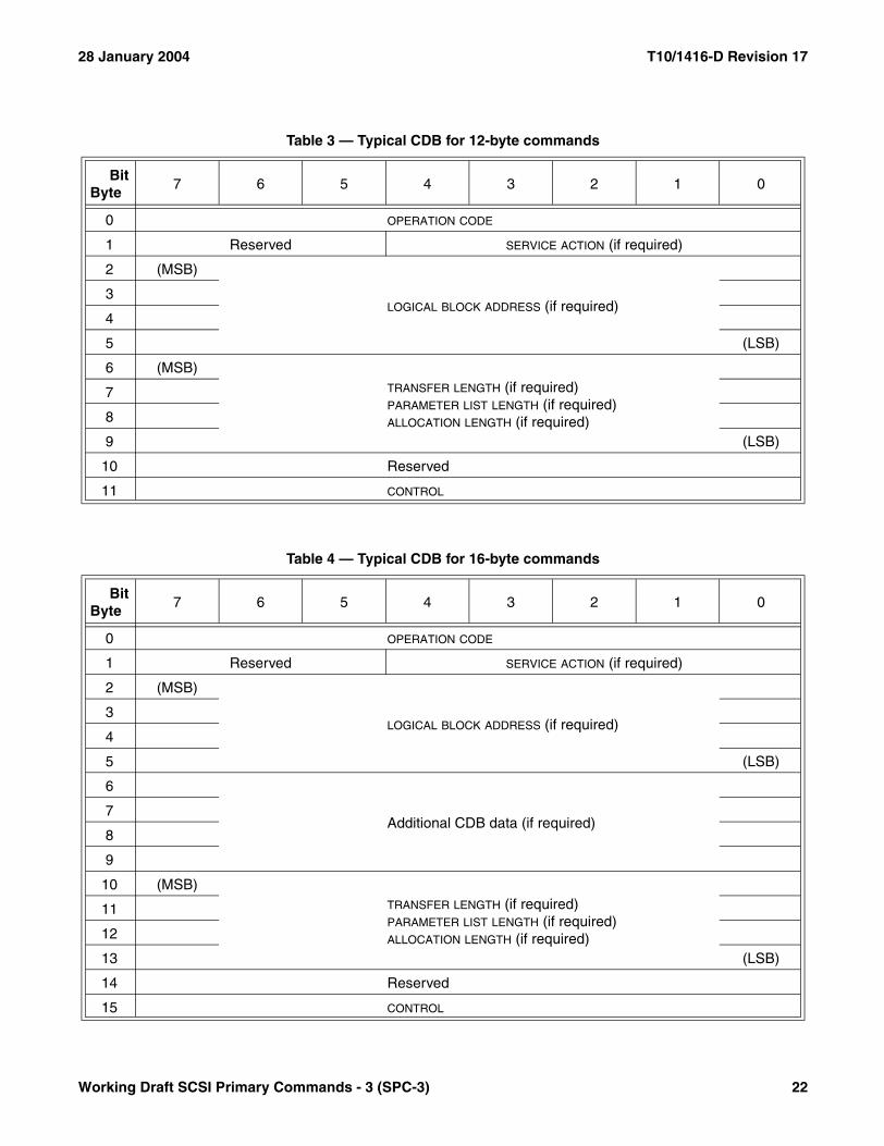
28 January 2004 T10/1416-D Revision 17
Table 3 — Typical CDB for 12-byte commands
BitByte
7 6 5 4 3 2 1 0
0 OPERATION CODE
1 Reserved SERVICE ACTION (if required)
2 (MSB)
LOGICAL BLOCK ADDRESS (if required)3
4
5 (LSB)
6 (MSB)TRANSFER LENGTH (if required)PARAMETER LIST LENGTH (if required)ALLOCATION LENGTH (if required)
7
8
9 (LSB)
10 Reserved
11 CONTROL
Table 4 — Typical CDB for 16-byte commands
BitByte
7 6 5 4 3 2 1 0
0 OPERATION CODE
1 Reserved SERVICE ACTION (if required)
2 (MSB)
LOGICAL BLOCK ADDRESS (if required)3
4
5 (LSB)
6
Additional CDB data (if required)7
8
9
10 (MSB)TRANSFER LENGTH (if required)PARAMETER LIST LENGTH (if required)ALLOCATION LENGTH (if required)
11
12
13 (LSB)
14 Reserved
15 CONTROL
Working Draft SCSI Primary Commands - 3 (SPC-3) 22

T10/1416-D Revision 17 28 January 2004
Table 5 — Typical CDB for long LBA 16-byte commands
BitByte
7 6 5 4 3 2 1 0
0 OPERATION CODE
1 Reserved miscellaneous CDB information
2 (MSB)
LOGICAL BLOCK ADDRESS
3
4
5
6
7
8
9 (LSB)
10 (MSB)TRANSFER LENGTH (if required)PARAMETER LIST LENGTH (if required)ALLOCATION LENGTH (if required)
11
12
13 (LSB)
14 Reserved
15 CONTROL
23 Working Draft SCSI Primary Commands - 3 (SPC-3)
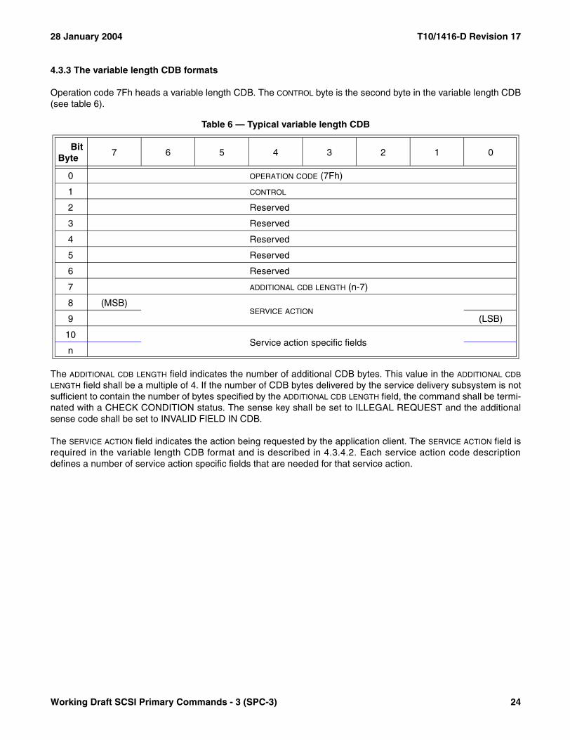
28 January 2004 T10/1416-D Revision 17
4.3.3 The variable length CDB formats
Operation code 7Fh heads a variable length CDB. The CONTROL byte is the second byte in the variable length CDB(see table 6).
The ADDITIONAL CDB LENGTH field indicates the number of additional CDB bytes. This value in the ADDITIONAL CDB
LENGTH field shall be a multiple of 4. If the number of CDB bytes delivered by the service delivery subsystem is notsufficient to contain the number of bytes specified by the ADDITIONAL CDB LENGTH field, the command shall be termi-nated with a CHECK CONDITION status. The sense key shall be set to ILLEGAL REQUEST and the additionalsense code shall be set to INVALID FIELD IN CDB.
The SERVICE ACTION field indicates the action being requested by the application client. The SERVICE ACTION field isrequired in the variable length CDB format and is described in 4.3.4.2. Each service action code descriptiondefines a number of service action specific fields that are needed for that service action.
Table 6 — Typical variable length CDB
BitByte
7 6 5 4 3 2 1 0
0 OPERATION CODE (7Fh)
1 CONTROL
2 Reserved
3 Reserved
4 Reserved
5 Reserved
6 Reserved
7 ADDITIONAL CDB LENGTH (n-7)
8 (MSB)SERVICE ACTION
9 (LSB)
10Service action specific fields
n
Working Draft SCSI Primary Commands - 3 (SPC-3) 24

T10/1416-D Revision 17 28 January 2004
A 32-byte variable length CDB format is defined for long LBA operations (see table 7).
4.3.4 Common CDB fields
4.3.4.1 Operation code
The first byte of a SCSI CDB shall contain an operation code identifying the operation being requested by the CDB.Some operation codes provide for modification of their operation based on a service action (see 4.3.4.2). In suchcases, the combination of operation code value and service action code value may be modeled as a single, uniquecommand determinate. The location of the SERVICE ACTION field in the CDB varies depending on the operation codevalue.
The OPERATION CODE (see table 8) of the CDB has a GROUP CODE field and a COMMAND CODE field. The three-bitGROUP CODE field provides for eight groups of command codes. The five-bit COMMAND CODE field provides forthirty-two command codes in each group. A total of 256 possible operation codes exist. Operation codes aredefined in this standard and other command standards (see 3.1.17). The group code value shall determine thelength of the CDB (see table 9).
Table 7 — Typical variable length CDB for long LBA 32-byte commands
BitByte
7 6 5 4 3 2 1 0
0 OPERATION CODE (7Fh)
1 CONTROL
2Reserved
4
5 Reserved
6 Reserved
7 ADDITIONAL CDB LENGTH (18h)
8 (MSB)SERVICE ACTION
9 (LSB)
10 Reserved DPO FUA Reserved
11 Reserved
12 (MSB)LOGICAL BLOCK ADDRESS
19 (LSB)
20Additional CDB data
27
28 (MSB) TRANSFER LENGTH (if required)PARAMETER LIST LENGTH (if required)ALLOCATION LENGTH (if required)31 (LSB)
Table 8 — OPERATION CODE byte
Bit 7 6 5 4 3 2 1 0
GROUP CODE COMMAND CODE
25 Working Draft SCSI Primary Commands - 3 (SPC-3)
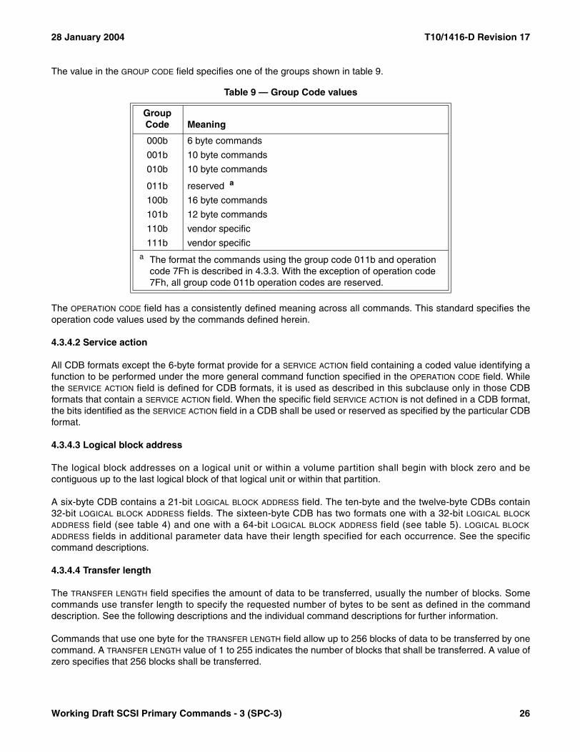
28 January 2004 T10/1416-D Revision 17
The value in the GROUP CODE field specifies one of the groups shown in table 9.
The OPERATION CODE field has a consistently defined meaning across all commands. This standard specifies theoperation code values used by the commands defined herein.
4.3.4.2 Service action
All CDB formats except the 6-byte format provide for a SERVICE ACTION field containing a coded value identifying afunction to be performed under the more general command function specified in the OPERATION CODE field. Whilethe SERVICE ACTION field is defined for CDB formats, it is used as described in this subclause only in those CDBformats that contain a SERVICE ACTION field. When the specific field SERVICE ACTION is not defined in a CDB format,the bits identified as the SERVICE ACTION field in a CDB shall be used or reserved as specified by the particular CDBformat.
4.3.4.3 Logical block address
The logical block addresses on a logical unit or within a volume partition shall begin with block zero and becontiguous up to the last logical block of that logical unit or within that partition.
A six-byte CDB contains a 21-bit LOGICAL BLOCK ADDRESS field. The ten-byte and the twelve-byte CDBs contain32-bit LOGICAL BLOCK ADDRESS fields. The sixteen-byte CDB has two formats one with a 32-bit LOGICAL BLOCK
ADDRESS field (see table 4) and one with a 64-bit LOGICAL BLOCK ADDRESS field (see table 5). LOGICAL BLOCK
ADDRESS fields in additional parameter data have their length specified for each occurrence. See the specificcommand descriptions.
4.3.4.4 Transfer length
The TRANSFER LENGTH field specifies the amount of data to be transferred, usually the number of blocks. Somecommands use transfer length to specify the requested number of bytes to be sent as defined in the commanddescription. See the following descriptions and the individual command descriptions for further information.
Commands that use one byte for the TRANSFER LENGTH field allow up to 256 blocks of data to be transferred by onecommand. A TRANSFER LENGTH value of 1 to 255 indicates the number of blocks that shall be transferred. A value ofzero specifies that 256 blocks shall be transferred.
Table 9 — Group Code values
Group Code Meaning
000b 6 byte commands
001b 10 byte commands
010b 10 byte commands
011b reserved a
100b 16 byte commands
101b 12 byte commands
110b vendor specific
111b vendor specifica The format the commands using the group code 011b and operation
code 7Fh is described in 4.3.3. With the exception of operation code 7Fh, all group code 011b operation codes are reserved.
Working Draft SCSI Primary Commands - 3 (SPC-3) 26
T10/1416-D Revision 17 28 January 2004
In commands that use multiple bytes for the TRANSFER LENGTH field, a transfer length of zero indicates that no datatransfer shall take place. A value of one or greater indicates the number of blocks that shall be transferred.
Refer to the specific command description for further information.
4.3.4.5 Parameter list length
The PARAMETER LIST LENGTH field is used to specify the number of bytes sent from the Data-Out Buffer. This field istypically used in CDBs for parameters that are sent to a device server (e.g., mode parameters, diagnostic param-eters, log parameters). A parameter length of zero indicates that no data shall be transferred. This condition shallnot be considered as an error.
4.3.4.6 Allocation length
The ALLOCATION LENGTH field specifies the maximum number of bytes that an application client has allocated forreturned data. An allocation length of zero indicates that no data shall be transferred. This condition shall not beconsidered as an error. The device server shall terminate transfers to the Data-In Buffer when allocation lengthbytes have been transferred or when all available data have been transferred, whichever is less. The allocationlength is used to limit the maximum amount of data (e.g., sense data, mode data, log data, diagnostic data)returned to an application client. If the information being transferred to the Data-In Buffer includes fields containingcounts of the number of bytes in some or all of the data, the contents of these fields shall not be altered to reflectthe truncation, if any, that results from an insufficient ALLOCATION LENGTH value, unless the standard that describesthe Data-In Buffer format specifically states otherwise.
If the amount of information to be transferred exceeds the maximum value that may be specified in the ALLOCATION
LENGTH field the device server shall transfer no data and return a CHECK CONDITION status; the sense key shallbe set to ILLEGAL REQUEST and the additional sense code shall be set to INVALID FIELD IN CDB.
4.3.4.7 Control
The contents of the CONTROL field are defined in SAM-3. The CONTROL field has a consistently defined meaningacross all commands.
4.4 Data field requirements
4.4.1 ASCII data field requirements
ASCII data fields shall contain only ASCII graphic codes (i.e., code values 20h through 7Eh).
ASCII data fields described as being left-aligned shall have any unused bytes at the end of the field (i.e., highestoffset) and the unused bytes shall be filled with ASCII space characters (20h).
ASCII data fields described as being right-aligned shall have any unused bytes at the start of the field (i.e., lowestoffset) and the unused bytes shall be filled with ASCII space characters (20h).
4.4.2 Null data field termination and zero padding requirements
A data field that is described as being null-terminated shall have one byte containing an ASCII or UTF-8 null (00h)character in the last used byte (i.e., highest offset) of the field and all other bytes in the field shall not contain theASCII/UTF-8 null character.
27 Working Draft SCSI Primary Commands - 3 (SPC-3)
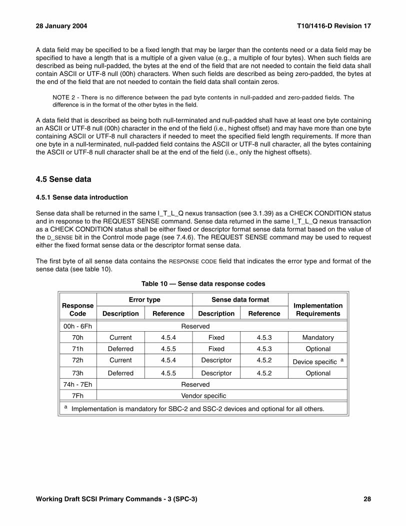
28 January 2004 T10/1416-D Revision 17
A data field may be specified to be a fixed length that may be larger than the contents need or a data field may bespecified to have a length that is a multiple of a given value (e.g., a multiple of four bytes). When such fields aredescribed as being null-padded, the bytes at the end of the field that are not needed to contain the field data shallcontain ASCII or UTF-8 null (00h) characters. When such fields are described as being zero-padded, the bytes atthe end of the field that are not needed to contain the field data shall contain zeros.
NOTE 2 - There is no difference between the pad byte contents in null-padded and zero-padded fields. Thedifference is in the format of the other bytes in the field.
A data field that is described as being both null-terminated and null-padded shall have at least one byte containingan ASCII or UTF-8 null (00h) character in the end of the field (i.e., highest offset) and may have more than one bytecontaining ASCII or UTF-8 null characters if needed to meet the specified field length requirements. If more thanone byte in a null-terminated, null-padded field contains the ASCII or UTF-8 null character, all the bytes containingthe ASCII or UTF-8 null character shall be at the end of the field (i.e., only the highest offsets).
4.5 Sense data
4.5.1 Sense data introduction
Sense data shall be returned in the same I_T_L_Q nexus transaction (see 3.1.39) as a CHECK CONDITION statusand in response to the REQUEST SENSE command. Sense data returned in the same I_T_L_Q nexus transactionas a CHECK CONDITION status shall be either fixed or descriptor format sense data format based on the value ofthe D_SENSE bit in the Control mode page (see 7.4.6). The REQUEST SENSE command may be used to requesteither the fixed format sense data or the descriptor format sense data.
The first byte of all sense data contains the RESPONSE CODE field that indicates the error type and format of thesense data (see table 10).
Table 10 — Sense data response codes
Response Code
Error type Sense data formatImplementation RequirementsDescription Reference Description Reference
00h - 6Fh Reserved
70h Current 4.5.4 Fixed 4.5.3 Mandatory
71h Deferred 4.5.5 Fixed 4.5.3 Optional
72h Current 4.5.4 Descriptor 4.5.2 Device specific a
73h Deferred 4.5.5 Descriptor 4.5.2 Optional
74h - 7Eh Reserved
7Fh Vendor specific
a Implementation is mandatory for SBC-2 and SSC-2 devices and optional for all others.
Working Draft SCSI Primary Commands - 3 (SPC-3) 28
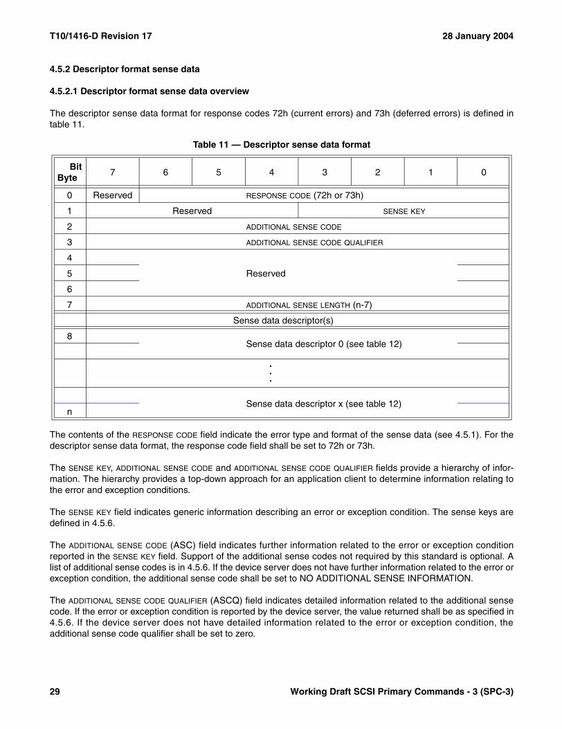
T10/1416-D Revision 17 28 January 2004
4.5.2 Descriptor format sense data
4.5.2.1 Descriptor format sense data overview
The descriptor sense data format for response codes 72h (current errors) and 73h (deferred errors) is defined intable 11.
The contents of the RESPONSE CODE field indicate the error type and format of the sense data (see 4.5.1). For thedescriptor sense data format, the response code field shall be set to 72h or 73h.
The SENSE KEY, ADDITIONAL SENSE CODE and ADDITIONAL SENSE CODE QUALIFIER fields provide a hierarchy of infor-mation. The hierarchy provides a top-down approach for an application client to determine information relating tothe error and exception conditions.
The SENSE KEY field indicates generic information describing an error or exception condition. The sense keys aredefined in 4.5.6.
The ADDITIONAL SENSE CODE (ASC) field indicates further information related to the error or exception conditionreported in the SENSE KEY field. Support of the additional sense codes not required by this standard is optional. Alist of additional sense codes is in 4.5.6. If the device server does not have further information related to the error orexception condition, the additional sense code shall be set to NO ADDITIONAL SENSE INFORMATION.
The ADDITIONAL SENSE CODE QUALIFIER (ASCQ) field indicates detailed information related to the additional sensecode. If the error or exception condition is reported by the device server, the value returned shall be as specified in4.5.6. If the device server does not have detailed information related to the error or exception condition, theadditional sense code qualifier shall be set to zero.
Table 11 — Descriptor sense data format
BitByte
7 6 5 4 3 2 1 0
0 Reserved RESPONSE CODE (72h or 73h)
1 Reserved SENSE KEY
2 ADDITIONAL SENSE CODE
3 ADDITIONAL SENSE CODE QUALIFIER
4
Reserved5
6
7 ADDITIONAL SENSE LENGTH (n-7)
Sense data descriptor(s)
8Sense data descriptor 0 (see table 12)
.
.
.
Sense data descriptor x (see table 12)n
29 Working Draft SCSI Primary Commands - 3 (SPC-3)

28 January 2004 T10/1416-D Revision 17
The ADDITIONAL SENSE LENGTH field indicates the number of additional sense bytes that follow. The additional senselength shall be less than or equal to 244 (i.e., limiting the total length of the sense data to 252 bytes). If the sensedata is being returned via a REQUEST SENSE command and the allocation length in the REQUEST SENSE CDBis too small to transfer all of the additional sense bytes, the additional sense length shall not be adjusted to reflectthe truncation.
Sense data descriptors (see table 12) provide specific sense information. A given type of sense data descriptorshall be included in the sense data only when the information it contains is valid.
The DESCRIPTOR TYPE field contains a type code (see table 13) that identifies the type of sense data descriptor. Nomore than one sense data descriptor of each type shall be included in the descriptor format sense data.
The ADDITIONAL LENGTH field indicates the number of sense data descriptor specific bytes that follow in the sensedata descriptor.
Table 12 — Sense data descriptor format
BitByte
7 6 5 4 3 2 1 0
0 DESCRIPTOR TYPE
1 ADDITIONAL LENGTH (n-1)
2Sense data descriptor specific
n
Table 13 — Sense data descriptor types
Type Description Reference
00h Information 4.5.2.2
01h Command specific information 4.5.2.3
02h Sense key specific 4.5.2.4
03h Field replaceable unit 4.5.2.5
04h Stream commands 4.5.2.6
05h Block commands 4.5.2.7
06h OSD object identification 4.5.2.8
07h OSD response integrity check value 4.5.2.9
08h - 7Fh Reserved
80h - FFh Vendor specific 4.5.2.10
Working Draft SCSI Primary Commands - 3 (SPC-3) 30
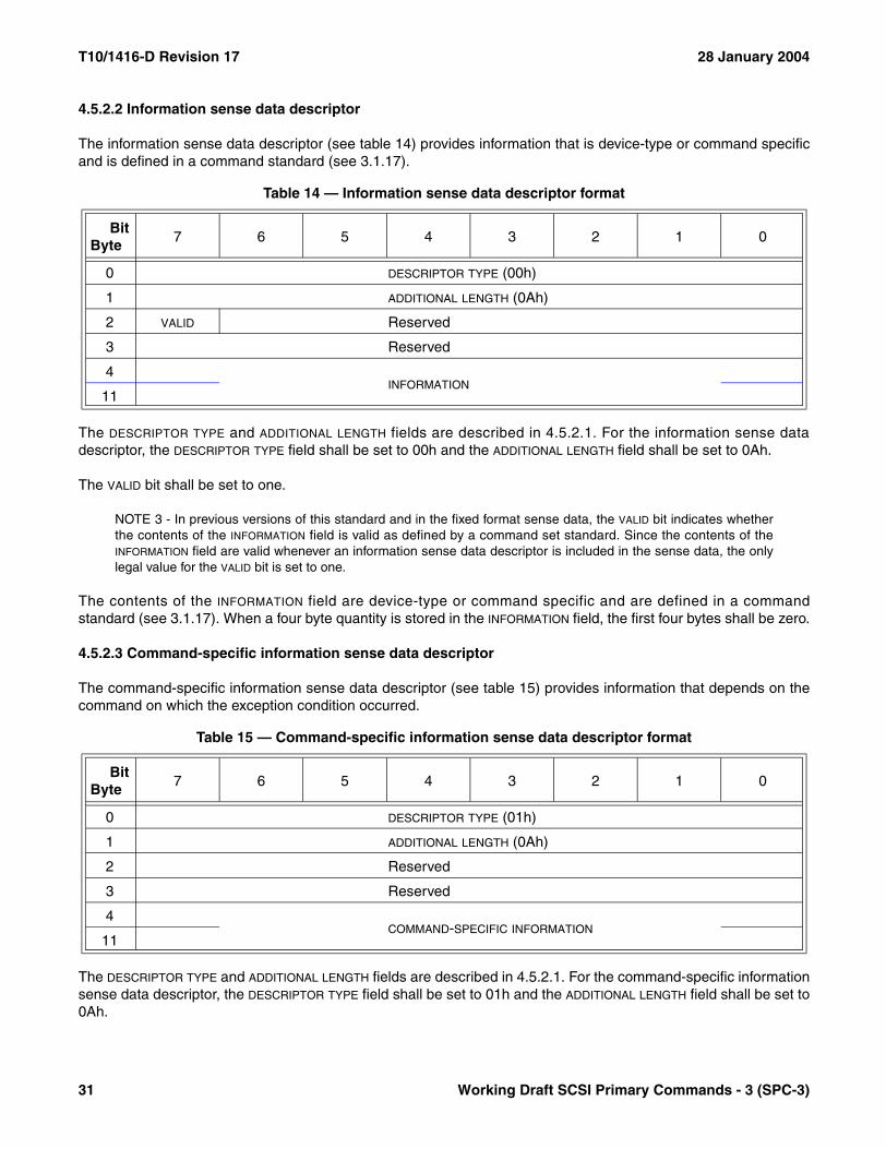
T10/1416-D Revision 17 28 January 2004
4.5.2.2 Information sense data descriptor
The information sense data descriptor (see table 14) provides information that is device-type or command specificand is defined in a command standard (see 3.1.17).
The DESCRIPTOR TYPE and ADDITIONAL LENGTH fields are described in 4.5.2.1. For the information sense datadescriptor, the DESCRIPTOR TYPE field shall be set to 00h and the ADDITIONAL LENGTH field shall be set to 0Ah.
The VALID bit shall be set to one.
NOTE 3 - In previous versions of this standard and in the fixed format sense data, the VALID bit indicates whetherthe contents of the INFORMATION field is valid as defined by a command set standard. Since the contents of theINFORMATION field are valid whenever an information sense data descriptor is included in the sense data, the onlylegal value for the VALID bit is set to one.
The contents of the INFORMATION field are device-type or command specific and are defined in a commandstandard (see 3.1.17). When a four byte quantity is stored in the INFORMATION field, the first four bytes shall be zero.
4.5.2.3 Command-specific information sense data descriptor
The command-specific information sense data descriptor (see table 15) provides information that depends on thecommand on which the exception condition occurred.
The DESCRIPTOR TYPE and ADDITIONAL LENGTH fields are described in 4.5.2.1. For the command-specific informationsense data descriptor, the DESCRIPTOR TYPE field shall be set to 01h and the ADDITIONAL LENGTH field shall be set to0Ah.
Table 14 — Information sense data descriptor format
BitByte
7 6 5 4 3 2 1 0
0 DESCRIPTOR TYPE (00h)
1 ADDITIONAL LENGTH (0Ah)
2 VALID Reserved
3 Reserved
4INFORMATION
11
Table 15 — Command-specific information sense data descriptor format
BitByte
7 6 5 4 3 2 1 0
0 DESCRIPTOR TYPE (01h)
1 ADDITIONAL LENGTH (0Ah)
2 Reserved
3 Reserved
4COMMAND-SPECIFIC INFORMATION
11
31 Working Draft SCSI Primary Commands - 3 (SPC-3)
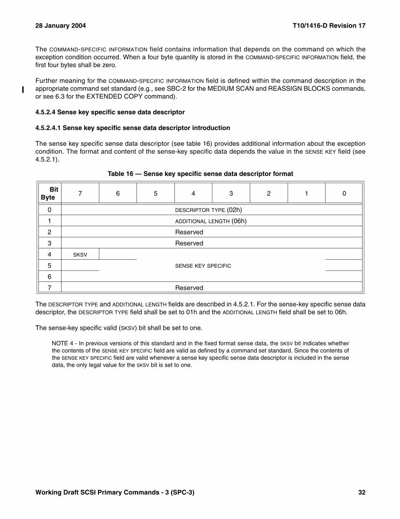
28 January 2004 T10/1416-D Revision 17
The COMMAND-SPECIFIC INFORMATION field contains information that depends on the command on which theexception condition occurred. When a four byte quantity is stored in the COMMAND-SPECIFIC INFORMATION field, thefirst four bytes shall be zero.
Further meaning for the COMMAND-SPECIFIC INFORMATION field is defined within the command description in theappropriate command set standard (e.g., see SBC-2 for the MEDIUM SCAN and REASSIGN BLOCKS commands,or see 6.3 for the EXTENDED COPY command).
4.5.2.4 Sense key specific sense data descriptor
4.5.2.4.1 Sense key specific sense data descriptor introduction
The sense key specific sense data descriptor (see table 16) provides additional information about the exceptioncondition. The format and content of the sense-key specific data depends the value in the SENSE KEY field (see4.5.2.1).
The DESCRIPTOR TYPE and ADDITIONAL LENGTH fields are described in 4.5.2.1. For the sense-key specific sense datadescriptor, the DESCRIPTOR TYPE field shall be set to 01h and the ADDITIONAL LENGTH field shall be set to 06h.
The sense-key specific valid (SKSV) bit shall be set to one.
NOTE 4 - In previous versions of this standard and in the fixed format sense data, the SKSV bit indicates whetherthe contents of the SENSE KEY SPECIFIC field are valid as defined by a command set standard. Since the contents ofthe SENSE KEY SPECIFIC field are valid whenever a sense key specific sense data descriptor is included in the sensedata, the only legal value for the SKSV bit is set to one.
Table 16 — Sense key specific sense data descriptor format
BitByte
7 6 5 4 3 2 1 0
0 DESCRIPTOR TYPE (02h)
1 ADDITIONAL LENGTH (06h)
2 Reserved
3 Reserved
4 SKSV
SENSE KEY SPECIFIC5
6
7 Reserved
Working Draft SCSI Primary Commands - 3 (SPC-3) 32

T10/1416-D Revision 17 28 January 2004
The definition of the SENSE KEY SPECIFIC field (see table 17) is determined by the value of the SENSE KEY field (see4.5.2.1).
4.5.2.4.2 Field pointer sense key specific data
If the sense key is ILLEGAL REQUEST, then the SENSE KEY SPECIFIC field shall be as shown in table 18.
The SKSV bit is described in 4.5.2.4.1 for descriptor format sense data and in 4.5.3 for fixed format sense data.
A command data (C/D) bit set to one indicates that the illegal parameter is in the CDB. A C/D bit set to zero indicatesthat the illegal parameter is in the data parameters sent by the application client in the Data-Out Buffer.
A bit pointer valid (BPV) bit set to zero indicates that the value in the BIT POINTER field is not valid. A BPV bit set toone indicates that the BIT POINTER field specifies which bit of the byte designated by the FIELD POINTER field is inerror. When a multiple-bit field is in error, the BIT POINTER field shall point to the first bit (i.e., the left-most bit) of thefield.
The FIELD POINTER field indicates which byte of the CDB or of the parameter data was in error. Bytes are numberedstarting from zero, as shown in the tables describing the commands and parameters. When a multiple-byte field isin error, the field pointer shall point to the first byte (i.e., the left-most byte) of the field. If several consecutive bytesare reserved, each shall be treated as a single-byte field.
NOTE 5 - The bytes identified as being in error are not necessarily the bytes that need to be changed to correct theproblem.
Table 17 — Sense key specific field definitions
Sense Key Sense Key Specific Field Definition Reference
ILLEGAL REQUEST Field pointer 4.5.2.4.2
HARDWARE ERROR,MEDIUM ERROR, orRECOVERED ERROR
Actual retry count 4.5.2.4.3
NO SENSE or NOT READY Progress indication 4.5.2.4.4
COPY ABORTED Segment pointer 4.5.2.4.5
All other sense keys The sense key specific sense data descriptor shall not appear in the descriptor format sense data and the SKSV bit (see 4.5.3) shall be set to zero in the fixed for-mat sense data.
Table 18 — Field pointer sense key specific data
BitByte
7 6 5 4 3 2 1 0
0 SKSV C/D Reserved BPV BIT POINTER
1 (MSB)FIELD POINTER
2 (LSB)
33 Working Draft SCSI Primary Commands - 3 (SPC-3)

28 January 2004 T10/1416-D Revision 17
4.5.2.4.3 Actual retry count sense key specific data
If the sense key is HARDWARE ERROR, MEDIUM ERROR, or RECOVERED ERROR the SENSE KEY SPECIFIC fieldshall be as shown in table 19.
The SKSV bit is described in 4.5.2.4.1 for descriptor format sense data and in 4.5.3 for fixed format sense data.
The ACTUAL RETRY COUNT field returns vendor specific information on the number of retries of the recoveryalgorithm used in attempting to recover an error or exception condition.
NOTE 6 - This field should be computed in the same way as the retry count fields within the Read-Write ErrorRecovery mode page.
4.5.2.4.4 Progress indication sense key specific data
If the sense key is NO SENSE or NOT READY, the SENSE KEY SPECIFIC field shall be as shown in table 20.
The SKSV bit is described in 4.5.2.4.1 for descriptor format sense data and in 4.5.3 for fixed format sense data.
The PROGRESS INDICATION field is a percent complete indication in which the returned value is a numerator that has65 536 (10000h) as its denominator. The progress indication shall be based upon the total operation.
NOTE 7 - The progress indication should be time related, however this is not an absolute requirement. Forexample, since format time varies with the number of defects encountered, etc., it is reasonable for the deviceserver to assign values to various steps within the process. The granularity of these steps should be small enoughto provide reasonable assurances to the application client that progress is being made.
Table 19 — Actual retry count sense key specific data
BitByte
7 6 5 4 3 2 1 0
0 SKSV Reserved
1 (MSB)ACTUAL RETRY COUNT
2 (LSB)
Table 20 — Progress indication sense key specific data
BitByte
7 6 5 4 3 2 1 0
0 SKSV Reserved
1 (MSB)PROGRESS INDICATION
2 (LSB)
Working Draft SCSI Primary Commands - 3 (SPC-3) 34
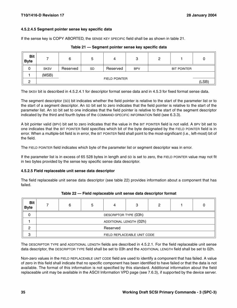
T10/1416-D Revision 17 28 January 2004
4.5.2.4.5 Segment pointer sense key specific data
If the sense key is COPY ABORTED, the SENSE KEY SPECIFIC field shall be as shown in table 21.
The SKSV bit is described in 4.5.2.4.1 for descriptor format sense data and in 4.5.3 for fixed format sense data.
The segment descriptor (SD) bit indicates whether the field pointer is relative to the start of the parameter list or tothe start of a segment descriptor. An SD bit set to zero indicates that the field pointer is relative to the start of theparameter list. An SD bit set to one indicates that the field pointer is relative to the start of the segment descriptorindicated by the third and fourth bytes of the COMMAND-SPECIFIC INFORMATION field (see 6.3.3).
A bit pointer valid (BPV) bit set to zero indicates that the value in the BIT POINTER field is not valid. A BPV bit set toone indicates that the BIT POINTER field specifies which bit of the byte designated by the FIELD POINTER field is inerror. When a multiple-bit field is in error, the BIT POINTER field shall point to the most-significant (i.e., left-most) bit ofthe field.
The FIELD POINTER field indicates which byte of the parameter list or segment descriptor was in error.
If the parameter list is in excess of 65 528 bytes in length and SD is set to zero, the FIELD POINTER value may not fitin two bytes provided by the sense key specific sense data descriptor.
4.5.2.5 Field replaceable unit sense data descriptor
The field replaceable unit sense data descriptor (see table 22) provides information about a component that hasfailed.
The DESCRIPTOR TYPE and ADDITIONAL LENGTH fields are described in 4.5.2.1. For the field replaceable unit sensedata descriptor, the DESCRIPTOR TYPE field shall be set to 03h and the ADDITIONAL LENGTH field shall be set to 02h.
Non-zero values in the FIELD REPLACEABLE UNIT CODE field are used to identify a component that has failed. A valueof zero in this field shall indicate that no specific component has been identified to have failed or that the data is notavailable. The format of this information is not specified by this standard. Additional information about the fieldreplaceable unit may be available in the ASCII Information VPD page (see 7.6.3), if supported by the device server.
Table 21 — Segment pointer sense key specific data
BitByte
7 6 5 4 3 2 1 0
0 SKSV Reserved SD Reserved BPV BIT POINTER
1 (MSB)FIELD POINTER
2 (LSB)
Table 22 — Field replaceable unit sense data descriptor format
BitByte
7 6 5 4 3 2 1 0
0 DESCRIPTOR TYPE (03h)
1 ADDITIONAL LENGTH (02h)
2 Reserved
3 FIELD REPLACEABLE UNIT CODE
35 Working Draft SCSI Primary Commands - 3 (SPC-3)

28 January 2004 T10/1416-D Revision 17
4.5.2.6 Stream commands sense data descriptor
The stream commands sense data descriptor (see table 23) contains fields defined for sequential devices (seeSSC-2).
The DESCRIPTOR TYPE and ADDITIONAL LENGTH fields are described in 4.5.2.1. For the stream commands sensedata descriptor, the DESCRIPTOR TYPE field shall be set to 04h and the ADDITIONAL LENGTH field shall be set to 02h.
See the SSC-2 READ and SPACE commands for examples of FILEMARK bit usage.
See the SSC-2 READ, SPACE, and WRITE commands for examples of end-of-medium (EOM) bit usage.
See the SSC-2 READ command for examples of incorrect length indicator (ILI) bit usage.
4.5.2.7 Block commands sense data descriptor
The block commands sense data descriptor (see table 24) contains fields defined for block devices (see SBC-2).
The DESCRIPTOR TYPE and ADDITIONAL LENGTH fields are described in 4.5.2.1. For the block commands sense datadescriptor, the DESCRIPTOR TYPE field shall be set to 05h and the ADDITIONAL LENGTH field shall be set to 02h.
See the SBC-2 READ LONG and WRITE LONG commands for examples of incorrect length indicator (ILI) bitusage.
Table 23 — Stream commands sense data descriptor format
BitByte
7 6 5 4 3 2 1 0
0 DESCRIPTOR TYPE (04h)
1 ADDITIONAL LENGTH (02h)
2 Reserved
3 FILEMARK EOM ILI Reserved
Table 24 — Block commands sense data descriptor format
BitByte
7 6 5 4 3 2 1 0
0 DESCRIPTOR TYPE (05h)
1 ADDITIONAL LENGTH (02h)
2 Reserved
3 Reserved ILI Reserved
Working Draft SCSI Primary Commands - 3 (SPC-3) 36
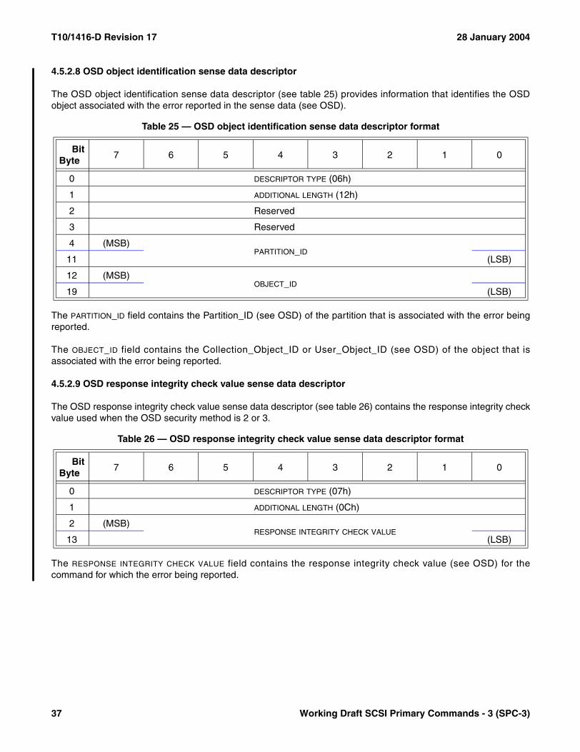
T10/1416-D Revision 17 28 January 2004
4.5.2.8 OSD object identification sense data descriptor
The OSD object identification sense data descriptor (see table 25) provides information that identifies the OSDobject associated with the error reported in the sense data (see OSD).
The PARTITION_ID field contains the Partition_ID (see OSD) of the partition that is associated with the error beingreported.
The OBJECT_ID field contains the Collection_Object_ID or User_Object_ID (see OSD) of the object that isassociated with the error being reported.
4.5.2.9 OSD response integrity check value sense data descriptor
The OSD response integrity check value sense data descriptor (see table 26) contains the response integrity checkvalue used when the OSD security method is 2 or 3.
The RESPONSE INTEGRITY CHECK VALUE field contains the response integrity check value (see OSD) for thecommand for which the error being reported.
Table 25 — OSD object identification sense data descriptor format
BitByte
7 6 5 4 3 2 1 0
0 DESCRIPTOR TYPE (06h)
1 ADDITIONAL LENGTH (12h)
2 Reserved
3 Reserved
4 (MSB)PARTITION_ID
11 (LSB)
12 (MSB)OBJECT_ID
19 (LSB)
Table 26 — OSD response integrity check value sense data descriptor format
BitByte
7 6 5 4 3 2 1 0
0 DESCRIPTOR TYPE (07h)
1 ADDITIONAL LENGTH (0Ch)
2 (MSB)RESPONSE INTEGRITY CHECK VALUE
13 (LSB)
37 Working Draft SCSI Primary Commands - 3 (SPC-3)
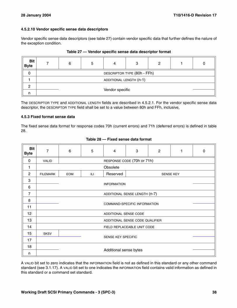
28 January 2004 T10/1416-D Revision 17
4.5.2.10 Vendor specific sense data descriptors
Vendor specific sense data descriptors (see table 27) contain vendor specific data that further defines the nature ofthe exception condition.
The DESCRIPTOR TYPE and ADDITIONAL LENGTH fields are described in 4.5.2.1. For the vendor specific sense datadescriptor, the DESCRIPTOR TYPE field shall be set to a value between 80h and FFh, inclusive,
4.5.3 Fixed format sense data
The fixed sense data format for response codes 70h (current errors) and 71h (deferred errors) is defined in table28.
A VALID bit set to zero indicates that the INFORMATION field is not as defined in this standard or any other commandstandard (see 3.1.17). A VALID bit set to one indicates the INFORMATION field contains valid information as defined inthis standard or a command set standard.
Table 27 — Vendor specific sense data descriptor format
BitByte
7 6 5 4 3 2 1 0
0 DESCRIPTOR TYPE (80h - FFh)
1 ADDITIONAL LENGTH (n-1)
2Vendor specific
n
Table 28 — Fixed sense data format
BitByte
7 6 5 4 3 2 1 0
0 VALID RESPONSE CODE (70h or 71h)
1 Obsolete
2 FILEMARK EOM ILI Reserved SENSE KEY
3INFORMATION
6
7 ADDITIONAL SENSE LENGTH (n-7)
8COMMAND-SPECIFIC INFORMATION
11
12 ADDITIONAL SENSE CODE
13 ADDITIONAL SENSE CODE QUALIFIER
14 FIELD REPLACEABLE UNIT CODE
15 SKSVSENSE KEY SPECIFIC
17
18Additional sense bytes
n
Working Draft SCSI Primary Commands - 3 (SPC-3) 38
T10/1416-D Revision 17 28 January 2004
The contents of the RESPONSE CODE field indicate the error type and format of the sense data (see 4.5.1). For thefixed sense data format, the RESPONSE CODE field shall be set to 70h or 71h.
The obsolete byte 1 contained information used by the COPY command.
The FILEMARK and EOM bits are described in 4.5.2.6.
The ILI bit is described in 4.5.2.6 and 4.5.2.7.
The SENSE KEY, ADDITIONAL SENSE CODE, and ADDITIONAL SENSE CODE QUALIFIER fields are described in 4.5.2.1.
The INFORMATION field is described in 4.5.2.2.
The ADDITIONAL SENSE LENGTH field indicates the number of additional sense bytes that follow. The additional senselength shall be less than or equal to 244 (i.e., limiting the total length of the sense data to 252 bytes). If the sensedata is being returned via a REQUEST SENSE command and the allocation length in the REQUEST SENSE CDBis too small to transfer all of the additional sense bytes, the additional sense length shall not be adjusted to reflectthe truncation.
The COMMAND-SPECIFIC INFORMATION field is described in 4.5.2.3.
The FIELD REPLACEABLE UNIT CODE field is described in 4.5.2.5.
A sense-key specific valid (SKSV) bit set to one indicates the SENSE KEY SPECIFIC field contains valid information asdefined in this standard. An SKSV bit set to zero indicates that the SENSE KEY SPECIFIC field is not as defined by thisstandard.
The SENSE KEY SPECIFIC field is described in 4.5.2.4.
The additional sense bytes may contain vendor specific data that further defines the nature of the exceptioncondition.
4.5.4 Current errors
Response codes 70h and 72h (current error) indicate that the sense data returned is the result of an error orexception condition on the task that returned the CHECK CONDITION status or a protocol specific failurecondition. This includes errors generated during processing of the command. It also includes errors not related toany command that are detected during processing of a command (e.g., disk servo-mechanism failure, off-trackerrors, or power-up test errors).
4.5.5 Deferred errors
Response codes 71h and 73h (deferred error) indicate that the sense data returned is the result of an error orexception condition that occurred during processing of a previous command for which GOOD, CONDITION MET,INTERMEDIATE, and INTERMEDIATE-CONDITION MET status has already been returned. Such commands areassociated with the use of the immediate bit and with some forms of caching. Device servers that implement thesefeatures shall implement deferred error reporting.
The deferred error may be indicated by returning CHECK CONDITION status to an application client accessedthrough the initiator port as described in this subclause.
39 Working Draft SCSI Primary Commands - 3 (SPC-3)
28 January 2004 T10/1416-D Revision 17
If the task terminates with CHECK CONDITION status and the sense data describes a deferred error the commandfor the terminated task shall not have been processed. After the device server detects a deferred error condition, itshall return a deferred error according to the following rules:
a) If no external intervention is necessary to recover a deferred error, a deferred error indication shall not bereturned unless required by the error handling parameters of a MODE SELECT command. The occurrenceof the error may be logged if statistical or error logging is supported;
b) If it is possible to associate a deferred error with an initiator port and with a particular function or aparticular subset of data, and the error is either unrecovered or required to be reported by the modeparameters, a deferred error indication shall be returned to an application client accessed through theinitiator port associated with the error. If an application client accessed through an initiator port other thanthe initiator port associated with the error attempts access to the particular function or subset of dataassociated with the deferred error and the TST field equals 000b (see 7.4.6), the device server shallrespond to the command with a BUSY or ACA ACTIVE status according to the requirements in SAM-3. Ifan application client accessed through an initiator port other than the initiator port associated with the errorattempts access to the particular function or subset of data associated with the deferred error and the TST
field equals 001b, the command attempting the access shall not be blocked by the deferred error and thecause of the deferred error may result in an error being reported for the command attempting the access;
c) If the device server is unable to associate a deferred error with an initiator port or with a particular subset ofdata, the device server shall return a deferred error indication to an application client accessed througheach initiator port. If multiple deferred errors have accumulated for an initiator port, only the last error shallbe returned;
d) If the SCSI target device is unable to associate a deferred error with a particular logical unit, it shall returna deferred error indication to an application client associated with every logical unit and shall return thedeferred error through an appropriate initiator port; or
e) If a task has never entered the enabled task state, and a deferred error occurs, the task shall be terminatedwith a CHECK CONDITION status and deferred error information returned in the sense data. If a deferrederror occurs after a task has entered the enabled task state and the task is affected by the error, the taskshall be terminated with a CHECK CONDITION status and the current error information shall be returnedin the sense data. In this case, if the current error information does not adequately define the deferred errorcondition, a deferred error may be returned after the current error information has been returned. If adeferred error occurs after a task has entered the enabled task state and the task completes successfully,the device server may choose to return the deferred error information after the completion of the currentcommand in conjunction with a subsequent command that has not begun processing.
NOTE 8 - A deferred error may indicate that an operation was unsuccessful long after GOOD status was returned.If the application client is unable to replicate or recover from other sources the data that is being written usingcached or buffered write operations, synchronization commands should be performed before the critical data isdestroyed. This is necessary for actions taken when deferred errors occur in the storing of the data. The synchro-nizing process should provide the necessary commands to allow returning CHECK CONDITION status and subse-quent returning of deferred error sense information after all cached or buffered operations are completed.
Working Draft SCSI Primary Commands - 3 (SPC-3) 40

T10/1416-D Revision 17 28 January 2004
4.5.6 Sense key and sense code definitions
The sense keys are defined in table 29.
Table 29 — Sense key descriptions (part 1 of 2)
Sense Key Description
0h NO SENSE: Indicates that there is no specific sense key information to be reported. This may occur for a successful command or for a command that receives CHECK CONDITION status because one of the FILEMARK, EOM, or ILI bits is set to one.
1h RECOVERED ERROR: Indicates that the last command completed successfully, with some recov-ery action performed by the device server. Details may be determined by examining the additional sense bytes and the INFORMATION field. When multiple recovered errors occur during one command, the choice of which error to report (e.g., first, last, most severe) is vendor specific.
2h NOT READY: Indicates that the logical unit addressed cannot be accessed. Operator intervention may be required to correct this condition.
3h MEDIUM ERROR: Indicates that the command terminated with a non-recovered error condition that may have been caused by a flaw in the medium or an error in the recorded data. This sense key may also be returned if the device server is unable to distinguish between a flaw in the medium and a specific hardware failure (i.e., sense key 4h).
4h HARDWARE ERROR: Indicates that the device server detected a non-recoverable hardware failure (e.g., controller failure, device failure, or parity error) while performing the command or during a self test.
5h ILLEGAL REQUEST: Indicates that:a) The command was addressed to an incorrect logical unit number (see SAM-3);b) The command had an invalid task attribute (see SAM-3);c) The command was addressed to a logical unit whose current configuration prohibits
processing the command;d) There was an illegal parameter in the CDB; ore) There was an illegal parameter in the additional parameters supplied as data for some
commands (e.g., PERSISTENT RESERVE OUT).If the device server detects an invalid parameter in the CDB, then it shall terminate the command without altering the medium. If the device server detects an invalid parameter in the additional parameters supplied as data, then the device server may have already altered the medium.
6h UNIT ATTENTION: Indicates that the removable medium may have been changed, a logical unit reset occurred, or an I_T nexus loss occurred involving the initiator port. For more information see SAM-3.
7h DATA PROTECT: Indicates that a command that reads or writes the medium was attempted on a block that is protected. The read or write operation is not performed.
8h BLANK CHECK: Indicates that a write-once device or a sequential-access device encountered blank medium or format-defined end-of-data indication while reading or that a write-once device encountered a non-blank medium while writing.
9h VENDOR SPECIFIC: This sense key is available for reporting vendor specific conditions.
Ah COPY ABORTED: Indicates an EXTENDED COPY command was aborted due to an error condition on the source device, the destination device, or both (see 6.3.3).
Bh ABORTED COMMAND: Indicates that the device server aborted the command. The application client may be able to recover by trying the command again.
41 Working Draft SCSI Primary Commands - 3 (SPC-3)

28 January 2004 T10/1416-D Revision 17
The additional sense codes and additional sense code qualifiers are defined in table 30.
Ch Obsolete
Dh VOLUME OVERFLOW: Indicates that a buffered SCSI device has reached the end-of-partition and data may remain in the buffer that has not been written to the medium. One or more RECOVER BUFFERED DATA command(s) may be issued to read the unwritten data from the buffer. (See SSC-2.)
Eh MISCOMPARE: Indicates that the source data did not match the data read from the medium.
Fh Reserved
Table 30 — ASC and ASCQ assignments (part 1 of 15)
D - DIRECT ACCESS BLOCK DEVICE (SBC) Device Column key. T - SEQUENTIAL ACCESS DEVICE (SSC-2) blank = code not used. L - PRINTER DEVICE (SSC) not blank = code used. P - PROCESSOR DEVICE (SPC-2). . W- WRITE ONCE BLOCK DEVICE (SBC). . R - CD/DVD DEVICE (MMC-3). . O- OPTICAL MEMORY BLOCK DEVICE (SBC). . . M- MEDIA CHANGER DEVICE (SMC-2). . . A - STORAGE ARRAY DEVICE (SCC-2). . . E - ENCLOSURE SERVICES DEVICE (SES). . . . B - SIMPLIFIED DIRECT-ACCESS DEVICE (RBC). . . . K - OPTICAL CARD READER/WRITER DEVICE (OCRW). . . . V - AUTOMATION/DRIVE INTERFACE (ADC). . . . . F - OBJECT-BASED STORAGE (OSD). . . . .
ASC ASCQ D T L P W R O M A E B K V F Description20h 0Bh D T P W R O M A E B K ACCESS DENIED - ACL LUN CONFLICT20h 08h D T P W R O M A E B K ACCESS DENIED - ENROLLMENT CONFLICT20h 01h D T P W R O M A E B K ACCESS DENIED - INITIATOR PENDING-ENROLLED20h 09h D T P W R O M A E B K ACCESS DENIED - INVALID LU IDENTIFIER20h 03h D T P W R O M A E B K ACCESS DENIED - INVALID MGMT ID KEY20h 0Ah D T P W R O M A E B K ACCESS DENIED - INVALID PROXY TOKEN20h 02h D T P W R O M A E B K ACCESS DENIED - NO ACCESS RIGHTS4Bh 03h D T P W R O M A E B K ACK/NAK TIMEOUT67h 02h A ADD LOGICAL UNIT FAILED13h 00h D W O B K ADDRESS MARK NOT FOUND FOR DATA FIELD12h 00h D W O B K ADDRESS MARK NOT FOUND FOR ID FIELD67h 08h A ASSIGN FAILURE OCCURRED27h 03h T R ASSOCIATED WRITE PROTECT2Ah 06h D T L P W R O M A E B K V F ASYMMETRIC ACCESS STATE CHANGED47h 04h D T L P W R O M A E B K V F ASYNCHRONOUS INFORMATION PROTECTION ERROR DETECTED67h 06h A ATTACHMENT OF LOGICAL UNIT FAILED00h 11h R AUDIO PLAY OPERATION IN PROGRESS00h 12h R AUDIO PLAY OPERATION PAUSED00h 14h R AUDIO PLAY OPERATION STOPPED DUE TO ERROR00h 13h R AUDIO PLAY OPERATION SUCCESSFULLY COMPLETED66h 00h AUTOMATIC DOCUMENT FEEDER COVER UP66h 01h AUTOMATIC DOCUMENT FEEDER LIFT UPAnnex C contains the ASC and ASCQ assignments in numeric order.
Table 29 — Sense key descriptions (part 2 of 2)
Sense Key Description
Working Draft SCSI Primary Commands - 3 (SPC-3) 42
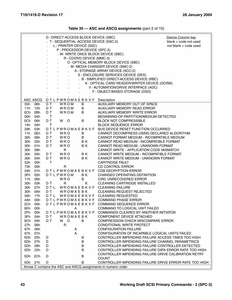
T10/1416-D Revision 17 28 January 2004
55h 06h D T W R O M B AUXILIARY MEMORY OUT OF SPACE11h 12h D T W R O M B AUXILIARY MEMORY READ ERROR0Ch 0Bh D T W R O M B AUXILIARY MEMORY WRITE ERROR00h 04h T BEGINNING-OF-PARTITION/MEDIUM DETECTED0Ch 06h D T W O B BLOCK NOT COMPRESSIBLE14h 04h T BLOCK SEQUENCE ERROR29h 03h D T L P W R O M A E B K V F BUS DEVICE RESET FUNCTION OCCURRED11h 0Eh D T W R O B CANNOT DECOMPRESS USING DECLARED ALGORITHM30h 06h D T W R O B CANNOT FORMAT MEDIUM - INCOMPATIBLE MEDIUM30h 02h D T W R O B K CANNOT READ MEDIUM - INCOMPATIBLE FORMAT30h 01h D T W R O B K CANNOT READ MEDIUM - UNKNOWN FORMAT30h 08h R CANNOT WRITE - APPLICATION CODE MISMATCH30h 05h D T W R O B K CANNOT WRITE MEDIUM - INCOMPATIBLE FORMAT30h 04h D T W R O B K CANNOT WRITE MEDIUM - UNKNOWN FORMAT52h 00h T CARTRIDGE FAULT73h 00h R CD CONTROL ERROR24h 01h D T L P W R O M A E B K V F CDB DECRYPTION ERROR3Fh 02h D T L P W R O M B K CHANGED OPERATING DEFINITION11h 06h W R O B CIRC UNRECOVERED ERROR30h 03h D T R K CLEANING CARTRIDGE INSTALLED30h 07h D T L W R O M A E B K V F CLEANING FAILURE30h 0Ah D T W R O M A E B K CLEANING REQUEST REJECTED00h 17h D T L W R O M A E B K V F CLEANING REQUESTED4Ah 00h D T L P W R O M A E B K V F COMMAND PHASE ERROR2Ch 00h D T L P W R O M A E B K V F COMMAND SEQUENCE ERROR6Eh 00h A COMMAND TO LOGICAL UNIT FAILED2Fh 00h D T L P W R O M A E B K V F COMMANDS CLEARED BY ANOTHER INITIATOR3Fh 04h D T W R O M A E B K COMPONENT DEVICE ATTACHED0Ch 04h D T W O B COMPRESSION CHECK MISCOMPARE ERROR27h 06h R CONDITIONAL WRITE PROTECT67h 00h A CONFIGURATION FAILURE67h 01h A CONFIGURATION OF INCAPABLE LOGICAL UNITS FAILED5Dh 25h D B CONTROLLER IMPENDING FAILURE ACCESS TIMES TOO HIGH5Dh 27h D B CONTROLLER IMPENDING FAILURE CHANNEL PARAMETRICS5Dh 28h D B CONTROLLER IMPENDING FAILURE CONTROLLER DETECTED5Dh 22h D B CONTROLLER IMPENDING FAILURE DATA ERROR RATE TOO HIGH
5Dh 2Ch D BCONTROLLER IMPENDING FAILURE DRIVE CALIBRATION RETRY COUNT
5Dh 21h D B CONTROLLER IMPENDING FAILURE DRIVE ERROR RATE TOO HIGH
Table 30 — ASC and ASCQ assignments (part 2 of 15)
D - DIRECT ACCESS BLOCK DEVICE (SBC) Device Column key. T - SEQUENTIAL ACCESS DEVICE (SSC-2) blank = code not used. L - PRINTER DEVICE (SSC) not blank = code used. P - PROCESSOR DEVICE (SPC-2). . W- WRITE ONCE BLOCK DEVICE (SBC). . R - CD/DVD DEVICE (MMC-3). . O- OPTICAL MEMORY BLOCK DEVICE (SBC). . . M- MEDIA CHANGER DEVICE (SMC-2). . . A - STORAGE ARRAY DEVICE (SCC-2). . . E - ENCLOSURE SERVICES DEVICE (SES). . . . B - SIMPLIFIED DIRECT-ACCESS DEVICE (RBC). . . . K - OPTICAL CARD READER/WRITER DEVICE (OCRW). . . . V - AUTOMATION/DRIVE INTERFACE (ADC). . . . . F - OBJECT-BASED STORAGE (OSD). . . . .
ASC ASCQ D T L P W R O M A E B K V F Description
Annex C contains the ASC and ASCQ assignments in numeric order.
43 Working Draft SCSI Primary Commands - 3 (SPC-3)

28 January 2004 T10/1416-D Revision 17
5Dh 20h D B CONTROLLER IMPENDING FAILURE GENERAL HARD DRIVE FAILURE5Dh 23h D B CONTROLLER IMPENDING FAILURE SEEK ERROR RATE TOO HIGH5Dh 2Ah D B CONTROLLER IMPENDING FAILURE SEEK TIME PERFORMANCE5Dh 2Bh D B CONTROLLER IMPENDING FAILURE SPIN-UP RETRY COUNT5Dh 26h D B CONTROLLER IMPENDING FAILURE START UNIT TIMES TOO HIGH5Dh 29h D B CONTROLLER IMPENDING FAILURE THROUGHPUT PERFORMANCE5Dh 24h D B CONTROLLER IMPENDING FAILURE TOO MANY BLOCK REASSIGNS2Bh 00h D T L P W R O K COPY CANNOT EXECUTE SINCE HOST CANNOT DISCONNECT
6Fh 00h RCOPY PROTECTION KEY EXCHANGE FAILURE - AUTHENTICATION FAILURE
6Fh 02h RCOPY PROTECTION KEY EXCHANGE FAILURE - KEY NOT ESTABLISHED
6Fh 01h R COPY PROTECTION KEY EXCHANGE FAILURE - KEY NOT PRESENT26h 0Dh D T L P W R O K COPY SEGMENT GRANULARITY VIOLATION0Dh 05h D T L P W R O A K COPY TARGET DEVICE DATA OVERRUN0Dh 04h D T L P W R O A K COPY TARGET DEVICE DATA UNDERRUN0Dh 02h D T L P W R O A K COPY TARGET DEVICE NOT REACHABLE67h 07h A CREATION OF LOGICAL UNIT FAILED2Ch 04h R CURRENT PROGRAM AREA IS EMPTY2Ch 03h R CURRENT PROGRAM AREA IS NOT EMPTY30h 09h R CURRENT SESSION NOT FIXATED FOR APPEND10h 02h D T W O DATA BLOCK APPLICATION TAG CHECK FAILED10h 01h D T W O DATA BLOCK GUARD CHECK FAILED10h 03h D T W O DATA BLOCK REFERENCE TAG CHECK FAILED5Dh 35h D B DATA CHANNEL IMPENDING FAILURE ACCESS TIMES TOO HIGH5Dh 37h D B DATA CHANNEL IMPENDING FAILURE CHANNEL PARAMETRICS5Dh 38h D B DATA CHANNEL IMPENDING FAILURE CONTROLLER DETECTED5Dh 32h D B DATA CHANNEL IMPENDING FAILURE DATA ERROR RATE TOO HIGH
5Dh 3Ch D BDATA CHANNEL IMPENDING FAILURE DRIVE CALIBRATION RETRY COUNT
5Dh 31h D B DATA CHANNEL IMPENDING FAILURE DRIVE ERROR RATE TOO HIGH
5Dh 30h D BDATA CHANNEL IMPENDING FAILURE GENERAL HARD DRIVE FAILURE
5Dh 33h D B DATA CHANNEL IMPENDING FAILURE SEEK ERROR RATE TOO HIGH5Dh 3Ah D B DATA CHANNEL IMPENDING FAILURE SEEK TIME PERFORMANCE5Dh 3Bh D B DATA CHANNEL IMPENDING FAILURE SPIN-UP RETRY COUNT5Dh 36h D B DATA CHANNEL IMPENDING FAILURE START UNIT TIMES TOO HIGH5Dh 39h D B DATA CHANNEL IMPENDING FAILURE THROUGHPUT PERFORMANCE5Dh 34h D B DATA CHANNEL IMPENDING FAILURE TOO MANY BLOCK REASSIGNS
Table 30 — ASC and ASCQ assignments (part 3 of 15)
D - DIRECT ACCESS BLOCK DEVICE (SBC) Device Column key. T - SEQUENTIAL ACCESS DEVICE (SSC-2) blank = code not used. L - PRINTER DEVICE (SSC) not blank = code used. P - PROCESSOR DEVICE (SPC-2). . W- WRITE ONCE BLOCK DEVICE (SBC). . R - CD/DVD DEVICE (MMC-3). . O- OPTICAL MEMORY BLOCK DEVICE (SBC). . . M- MEDIA CHANGER DEVICE (SMC-2). . . A - STORAGE ARRAY DEVICE (SCC-2). . . E - ENCLOSURE SERVICES DEVICE (SES). . . . B - SIMPLIFIED DIRECT-ACCESS DEVICE (RBC). . . . K - OPTICAL CARD READER/WRITER DEVICE (OCRW). . . . V - AUTOMATION/DRIVE INTERFACE (ADC). . . . . F - OBJECT-BASED STORAGE (OSD). . . . .
ASC ASCQ D T L P W R O M A E B K V F Description
Annex C contains the ASC and ASCQ assignments in numeric order.
Working Draft SCSI Primary Commands - 3 (SPC-3) 44
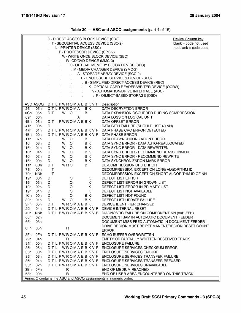
T10/1416-D Revision 17 28 January 2004
26h 05h D T L P W R O M A B K DATA DECRYPTION ERROR0Ch 05h D T W O B DATA EXPANSION OCCURRED DURING COMPRESSION69h 00h A DATA LOSS ON LOGICAL UNIT4Bh 05h D T P W R O M A E B K DATA OFFSET ERROR41h 00h D DATA PATH FAILURE (SHOULD USE 40 NN)47h 01h D T L P W R O M A E B K V F DATA PHASE CRC ERROR DETECTED4Bh 00h D T L P W R O M A E B K V F DATA PHASE ERROR11h 07h W O B DATA RE-SYNCHRONIZATION ERROR16h 03h D W O B K DATA SYNC ERROR - DATA AUTO-REALLOCATED16h 01h D W O B K DATA SYNC ERROR - DATA REWRITTEN16h 04h D W O B K DATA SYNC ERROR - RECOMMEND REASSIGNMENT16h 02h D W O B K DATA SYNC ERROR - RECOMMEND REWRITE16h 00h D W O B K DATA SYNCHRONIZATION MARK ERROR11h 0Dh D T W R O B DE-COMPRESSION CRC ERROR71h 00h T DECOMPRESSION EXCEPTION LONG ALGORITHM ID70h NNh T DECOMPRESSION EXCEPTION SHORT ALGORITHM ID OF NN19h 00h D O K DEFECT LIST ERROR19h 03h D O K DEFECT LIST ERROR IN GROWN LIST19h 02h D O K DEFECT LIST ERROR IN PRIMARY LIST19h 01h D O K DEFECT LIST NOT AVAILABLE1Ch 00h D O B K DEFECT LIST NOT FOUND32h 01h D W O B K DEFECT LIST UPDATE FAILURE3Fh 05h D T W R O M A E B K DEVICE IDENTIFIER CHANGED29h 04h D T L P W R O M A E B K V F DEVICE INTERNAL RESET40h NNh D T L P W R O M A E B K V F DIAGNOSTIC FAILURE ON COMPONENT NN (80H-FFH)66h 02h DOCUMENT JAM IN AUTOMATIC DOCUMENT FEEDER66h 03h DOCUMENT MISS FEED AUTOMATIC IN DOCUMENT FEEDER
6Fh 05h RDRIVE REGION MUST BE PERMANENT/REGION RESET COUNT ERROR
3Fh 0Fh D T L P W R O M A E B K V F ECHO BUFFER OVERWRITTEN72h 04h R EMPTY OR PARTIALLY WRITTEN RESERVED TRACK34h 00h D T L P W R O M A E B K V F ENCLOSURE FAILURE35h 05h D T L W R O M A E B K V F ENCLOSURE SERVICES CHECKSUM ERROR35h 00h D T L P W R O M A E B K V F ENCLOSURE SERVICES FAILURE35h 03h D T L P W R O M A E B K V F ENCLOSURE SERVICES TRANSFER FAILURE35h 04h D T L P W R O M A E B K V F ENCLOSURE SERVICES TRANSFER REFUSED35h 02h D T L P W R O M A E B K V F ENCLOSURE SERVICES UNAVAILABLE3Bh 0Fh R END OF MEDIUM REACHED63h 00h R END OF USER AREA ENCOUNTERED ON THIS TRACK
Table 30 — ASC and ASCQ assignments (part 4 of 15)
D - DIRECT ACCESS BLOCK DEVICE (SBC) Device Column key. T - SEQUENTIAL ACCESS DEVICE (SSC-2) blank = code not used. L - PRINTER DEVICE (SSC) not blank = code used. P - PROCESSOR DEVICE (SPC-2). . W- WRITE ONCE BLOCK DEVICE (SBC). . R - CD/DVD DEVICE (MMC-3). . O- OPTICAL MEMORY BLOCK DEVICE (SBC). . . M- MEDIA CHANGER DEVICE (SMC-2). . . A - STORAGE ARRAY DEVICE (SCC-2). . . E - ENCLOSURE SERVICES DEVICE (SES). . . . B - SIMPLIFIED DIRECT-ACCESS DEVICE (RBC). . . . K - OPTICAL CARD READER/WRITER DEVICE (OCRW). . . . V - AUTOMATION/DRIVE INTERFACE (ADC). . . . . F - OBJECT-BASED STORAGE (OSD). . . . .
ASC ASCQ D T L P W R O M A E B K V F Description
Annex C contains the ASC and ASCQ assignments in numeric order.
45 Working Draft SCSI Primary Commands - 3 (SPC-3)

28 January 2004 T10/1416-D Revision 17
00h 05h T L END-OF-DATA DETECTED14h 03h T END-OF-DATA NOT FOUND00h 02h T END-OF-PARTITION/MEDIUM DETECTED51h 00h T R O ERASE FAILURE51h 01h R ERASE FAILURE - INCOMPLETE ERASE OPERATION DETECTED00h 18h T ERASE OPERATION IN PROGRESS0Dh 00h D T L P W R O A K ERROR DETECTED BY THIRD PARTY TEMPORARY INITIATOR0Ah 00h D T L P W R O M A E B K V F ERROR LOG OVERFLOW11h 10h R ERROR READING ISRC NUMBER11h 0Fh R ERROR READING UPC/EAN NUMBER11h 02h D T W R O B K ERROR TOO LONG TO CORRECT38h 06h B ESN - DEVICE BUSY CLASS EVENT38h 04h B ESN - MEDIA CLASS EVENT38h 02h B ESN - POWER MANAGEMENT CLASS EVENT38h 00h B EVENT STATUS NOTIFICATION03h 02h T EXCESSIVE WRITE ERRORS67h 04h A EXCHANGE OF LOGICAL UNIT FAILED3Bh 07h L FAILED TO SENSE BOTTOM-OF-FORM3Bh 06h L FAILED TO SENSE TOP-OF-FORM5Dh 00h D T L P W R O M A E B K V F FAILURE PREDICTION THRESHOLD EXCEEDED5Dh FFh D T L P W R O M A E B K V F FAILURE PREDICTION THRESHOLD EXCEEDED (FALSE)00h 01h T FILEMARK DETECTED14h 02h T FILEMARK OR SETMARK NOT FOUND5Dh 65h D B FIRMWARE IMPENDING FAILURE ACCESS TIMES TOO HIGH5Dh 67h D B FIRMWARE IMPENDING FAILURE CHANNEL PARAMETRICS5Dh 68h D B FIRMWARE IMPENDING FAILURE CONTROLLER DETECTED5Dh 62h D B FIRMWARE IMPENDING FAILURE DATA ERROR RATE TOO HIGH5Dh 6Ch D B FIRMWARE IMPENDING FAILURE DRIVE CALIBRATION RETRY COUNT5Dh 61h D B FIRMWARE IMPENDING FAILURE DRIVE ERROR RATE TOO HIGH5Dh 60h D B FIRMWARE IMPENDING FAILURE GENERAL HARD DRIVE FAILURE5Dh 63h D B FIRMWARE IMPENDING FAILURE SEEK ERROR RATE TOO HIGH5Dh 6Ah D B FIRMWARE IMPENDING FAILURE SEEK TIME PERFORMANCE5Dh 6Bh D B FIRMWARE IMPENDING FAILURE SPIN-UP RETRY COUNT5Dh 66h D B FIRMWARE IMPENDING FAILURE START UNIT TIMES TOO HIGH5Dh 69h D B FIRMWARE IMPENDING FAILURE THROUGHPUT PERFORMANCE5Dh 64h D B FIRMWARE IMPENDING FAILURE TOO MANY BLOCK REASSIGNS09h 02h W R O K FOCUS SERVO FAILURE31h 01h D L R O B FORMAT COMMAND FAILED58h 00h O GENERATION DOES NOT EXIST
Table 30 — ASC and ASCQ assignments (part 5 of 15)
D - DIRECT ACCESS BLOCK DEVICE (SBC) Device Column key. T - SEQUENTIAL ACCESS DEVICE (SSC-2) blank = code not used. L - PRINTER DEVICE (SSC) not blank = code used. P - PROCESSOR DEVICE (SPC-2). . W- WRITE ONCE BLOCK DEVICE (SBC). . R - CD/DVD DEVICE (MMC-3). . O- OPTICAL MEMORY BLOCK DEVICE (SBC). . . M- MEDIA CHANGER DEVICE (SMC-2). . . A - STORAGE ARRAY DEVICE (SCC-2). . . E - ENCLOSURE SERVICES DEVICE (SES). . . . B - SIMPLIFIED DIRECT-ACCESS DEVICE (RBC). . . . K - OPTICAL CARD READER/WRITER DEVICE (OCRW). . . . V - AUTOMATION/DRIVE INTERFACE (ADC). . . . . F - OBJECT-BASED STORAGE (OSD). . . . .
ASC ASCQ D T L P W R O M A E B K V F Description
Annex C contains the ASC and ASCQ assignments in numeric order.
Working Draft SCSI Primary Commands - 3 (SPC-3) 46

T10/1416-D Revision 17 28 January 2004
1Ch 02h D O B K GROWN DEFECT LIST NOT FOUND5Dh 15h D B HARDWARE IMPENDING FAILURE ACCESS TIMES TOO HIGH5Dh 17h D B HARDWARE IMPENDING FAILURE CHANNEL PARAMETRICS5Dh 18h D B HARDWARE IMPENDING FAILURE CONTROLLER DETECTED5Dh 12h D B HARDWARE IMPENDING FAILURE DATA ERROR RATE TOO HIGH
5Dh 1Ch D BHARDWARE IMPENDING FAILURE DRIVE CALIBRATION RETRY COUNT
5Dh 11h D B HARDWARE IMPENDING FAILURE DRIVE ERROR RATE TOO HIGH5Dh 10h D B HARDWARE IMPENDING FAILURE GENERAL HARD DRIVE FAILURE5Dh 13h D B HARDWARE IMPENDING FAILURE SEEK ERROR RATE TOO HIGH5Dh 1Ah D B HARDWARE IMPENDING FAILURE SEEK TIME PERFORMANCE5Dh 1Bh D B HARDWARE IMPENDING FAILURE SPIN-UP RETRY COUNT5Dh 16h D B HARDWARE IMPENDING FAILURE START UNIT TIMES TOO HIGH5Dh 19h D B HARDWARE IMPENDING FAILURE THROUGHPUT PERFORMANCE5Dh 14h D B HARDWARE IMPENDING FAILURE TOO MANY BLOCK REASSIGNS27h 01h D T W R O B K HARDWARE WRITE PROTECTED09h 04h D T W R O B HEAD SELECT FAULT00h 06h D T L P W R O M A E B K V F I/O PROCESS TERMINATED10h 00h D W O B K ID CRC OR ECC ERROR5Eh 03h D T L P W R O A K IDLE CONDITION ACTIVATED BY COMMAND5Eh 01h D T L P W R O A K IDLE CONDITION ACTIVATED BY TIMER20h 06h T ILLEGAL COMMAND WHILE IN EXPLICIT ADDRESS MODE20h 07h T ILLEGAL COMMAND WHILE IN IMPLICIT ADDRESS MODE20h 04h T ILLEGAL COMMAND WHILE IN WRITE CAPABLE STATE22h 00h D ILLEGAL FUNCTION (USE 20 00, 24 00, OR 26 00)64h 00h R ILLEGAL MODE FOR THIS TRACK2Ch 05h B ILLEGAL POWER CONDITION REQUEST2Ah 07h D T L P W R O M A E B K V F IMPLICIT ASYMMETRIC ACCESS STATE TRANSITION FAILED28h 01h D T W R O M B IMPORT OR EXPORT ELEMENT ACCESSED30h 00h D T W R O M B K INCOMPATIBLE MEDIUM INSTALLED11h 08h T INCOMPLETE BLOCK READ0Dh 03h D T L P W R O A K INCORRECT COPY TARGET DEVICE TYPE0Eh 02h D T P W R O M A E B K INFORMATION UNIT TOO LONG0Eh 01h D T P W R O M A E B K INFORMATION UNIT TOO SHORT47h 03h D T L P W R O M A E B K V F INFORMATION UNIT iuCRC ERROR DETECTED6Ah 00h A INFORMATIONAL, REFER TO LOG48h 00h D T L P W R O M A E B K V F INITIATOR DETECTED ERROR MESSAGE RECEIVED4Bh 06h D T P W R O M A E B K INITIATOR RESPONSE TIMEOUT26h 0Bh D T L P W R O K INLINE DATA LENGTH EXCEEDED
Table 30 — ASC and ASCQ assignments (part 6 of 15)
D - DIRECT ACCESS BLOCK DEVICE (SBC) Device Column key. T - SEQUENTIAL ACCESS DEVICE (SSC-2) blank = code not used. L - PRINTER DEVICE (SSC) not blank = code used. P - PROCESSOR DEVICE (SPC-2). . W- WRITE ONCE BLOCK DEVICE (SBC). . R - CD/DVD DEVICE (MMC-3). . O- OPTICAL MEMORY BLOCK DEVICE (SBC). . . M- MEDIA CHANGER DEVICE (SMC-2). . . A - STORAGE ARRAY DEVICE (SCC-2). . . E - ENCLOSURE SERVICES DEVICE (SES). . . . B - SIMPLIFIED DIRECT-ACCESS DEVICE (RBC). . . . K - OPTICAL CARD READER/WRITER DEVICE (OCRW). . . . V - AUTOMATION/DRIVE INTERFACE (ADC). . . . . F - OBJECT-BASED STORAGE (OSD). . . . .
ASC ASCQ D T L P W R O M A E B K V F Description
Annex C contains the ASC and ASCQ assignments in numeric order.
47 Working Draft SCSI Primary Commands - 3 (SPC-3)
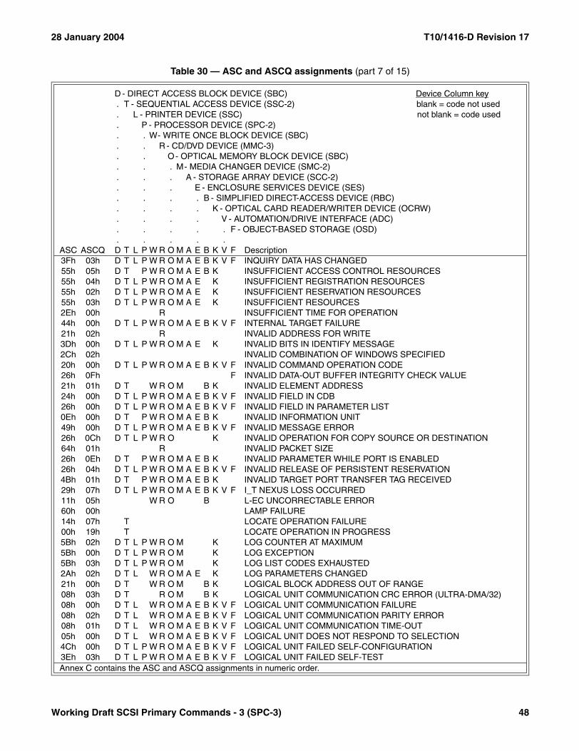
28 January 2004 T10/1416-D Revision 17
3Fh 03h D T L P W R O M A E B K V F INQUIRY DATA HAS CHANGED55h 05h D T P W R O M A E B K INSUFFICIENT ACCESS CONTROL RESOURCES55h 04h D T L P W R O M A E K INSUFFICIENT REGISTRATION RESOURCES55h 02h D T L P W R O M A E K INSUFFICIENT RESERVATION RESOURCES55h 03h D T L P W R O M A E K INSUFFICIENT RESOURCES2Eh 00h R INSUFFICIENT TIME FOR OPERATION44h 00h D T L P W R O M A E B K V F INTERNAL TARGET FAILURE21h 02h R INVALID ADDRESS FOR WRITE3Dh 00h D T L P W R O M A E K INVALID BITS IN IDENTIFY MESSAGE2Ch 02h INVALID COMBINATION OF WINDOWS SPECIFIED20h 00h D T L P W R O M A E B K V F INVALID COMMAND OPERATION CODE26h 0Fh F INVALID DATA-OUT BUFFER INTEGRITY CHECK VALUE21h 01h D T W R O M B K INVALID ELEMENT ADDRESS24h 00h D T L P W R O M A E B K V F INVALID FIELD IN CDB26h 00h D T L P W R O M A E B K V F INVALID FIELD IN PARAMETER LIST0Eh 00h D T P W R O M A E B K INVALID INFORMATION UNIT49h 00h D T L P W R O M A E B K V F INVALID MESSAGE ERROR26h 0Ch D T L P W R O K INVALID OPERATION FOR COPY SOURCE OR DESTINATION64h 01h R INVALID PACKET SIZE26h 0Eh D T P W R O M A E B K INVALID PARAMETER WHILE PORT IS ENABLED26h 04h D T L P W R O M A E B K V F INVALID RELEASE OF PERSISTENT RESERVATION4Bh 01h D T P W R O M A E B K INVALID TARGET PORT TRANSFER TAG RECEIVED29h 07h D T L P W R O M A E B K V F I_T NEXUS LOSS OCCURRED11h 05h W R O B L-EC UNCORRECTABLE ERROR60h 00h LAMP FAILURE14h 07h T LOCATE OPERATION FAILURE00h 19h T LOCATE OPERATION IN PROGRESS5Bh 02h D T L P W R O M K LOG COUNTER AT MAXIMUM5Bh 00h D T L P W R O M K LOG EXCEPTION5Bh 03h D T L P W R O M K LOG LIST CODES EXHAUSTED2Ah 02h D T L W R O M A E K LOG PARAMETERS CHANGED21h 00h D T W R O M B K LOGICAL BLOCK ADDRESS OUT OF RANGE08h 03h D T R O M B K LOGICAL UNIT COMMUNICATION CRC ERROR (ULTRA-DMA/32)08h 00h D T L W R O M A E B K V F LOGICAL UNIT COMMUNICATION FAILURE08h 02h D T L W R O M A E B K V F LOGICAL UNIT COMMUNICATION PARITY ERROR08h 01h D T L W R O M A E B K V F LOGICAL UNIT COMMUNICATION TIME-OUT05h 00h D T L W R O M A E B K V F LOGICAL UNIT DOES NOT RESPOND TO SELECTION4Ch 00h D T L P W R O M A E B K V F LOGICAL UNIT FAILED SELF-CONFIGURATION3Eh 03h D T L P W R O M A E B K V F LOGICAL UNIT FAILED SELF-TEST
Table 30 — ASC and ASCQ assignments (part 7 of 15)
D - DIRECT ACCESS BLOCK DEVICE (SBC) Device Column key. T - SEQUENTIAL ACCESS DEVICE (SSC-2) blank = code not used. L - PRINTER DEVICE (SSC) not blank = code used. P - PROCESSOR DEVICE (SPC-2). . W- WRITE ONCE BLOCK DEVICE (SBC). . R - CD/DVD DEVICE (MMC-3). . O- OPTICAL MEMORY BLOCK DEVICE (SBC). . . M- MEDIA CHANGER DEVICE (SMC-2). . . A - STORAGE ARRAY DEVICE (SCC-2). . . E - ENCLOSURE SERVICES DEVICE (SES). . . . B - SIMPLIFIED DIRECT-ACCESS DEVICE (RBC). . . . K - OPTICAL CARD READER/WRITER DEVICE (OCRW). . . . V - AUTOMATION/DRIVE INTERFACE (ADC). . . . . F - OBJECT-BASED STORAGE (OSD). . . . .
ASC ASCQ D T L P W R O M A E B K V F Description
Annex C contains the ASC and ASCQ assignments in numeric order.
Working Draft SCSI Primary Commands - 3 (SPC-3) 48

T10/1416-D Revision 17 28 January 2004
3Eh 01h D T L P W R O M A E B K V F LOGICAL UNIT FAILURE5Dh 02h R LOGICAL UNIT FAILURE PREDICTION THRESHOLD EXCEEDED3Eh 00h D T L P W R O M A E B K V F LOGICAL UNIT HAS NOT SELF-CONFIGURED YET04h 01h D T L P W R O M A E B K V F LOGICAL UNIT IS IN PROCESS OF BECOMING READY
04h 0Ah D T L P W R O M A E B K V FLOGICAL UNIT NOT ACCESSIBLE, ASYMMETRIC ACCESS STATE TRANSITION
04h 0Bh D T L P W R O M A E B K V F LOGICAL UNIT NOT ACCESSIBLE, TARGET PORT IN STANDBY STATE
04h 0Ch D T L P W R O M A E B K V FLOGICAL UNIT NOT ACCESSIBLE, TARGET PORT IN UNAVAILABLE STATE
68h 00h A LOGICAL UNIT NOT CONFIGURED04h 10h D T W R O M B LOGICAL UNIT NOT READY, AUXILIARY MEMORY NOT ACCESSIBLE04h 00h D T L P W R O M A E B K V F LOGICAL UNIT NOT READY, CAUSE NOT REPORTABLE04h 04h D T L R O B LOGICAL UNIT NOT READY, FORMAT IN PROGRESS04h 02h D T L P W R O M A E B K V F LOGICAL UNIT NOT READY, INITIALIZING COMMAND REQUIRED04h 08h R LOGICAL UNIT NOT READY, LONG WRITE IN PROGRESS04h 03h D T L P W R O M A E B K V F LOGICAL UNIT NOT READY, MANUAL INTERVENTION REQUIRED04h 11h D T W R O M A E B V F LOGICAL UNIT NOT READY, NOTIFY (ENABLE SPINUP) REQUIRED04h 07h D T L P W R O M A E B K V F LOGICAL UNIT NOT READY, OPERATION IN PROGRESS04h 05h D T W O M A B K LOGICAL UNIT NOT READY, REBUILD IN PROGRESS04h 06h D T W O M A B K LOGICAL UNIT NOT READY, RECALCULATION IN PROGRESS04h 09h D T L P W R O M A E B K V F LOGICAL UNIT NOT READY, SELF-TEST IN PROGRESS25h 00h D T L P W R O M A E B K V F LOGICAL UNIT NOT SUPPORTED27h 02h D T W R O B K LOGICAL UNIT SOFTWARE WRITE PROTECTED3Eh 04h D T L P W R O M A E B K V F LOGICAL UNIT UNABLE TO UPDATE SELF-TEST LOG5Eh 00h D T L P W R O A K LOW POWER CONDITION ON15h 01h D T L W R O M B K MECHANICAL POSITIONING ERROR3Bh 16h R MECHANICAL POSITIONING OR CHANGER ERROR5Dh 01h R B MEDIA FAILURE PREDICTION THRESHOLD EXCEEDED53h 00h D T L W R O M B K MEDIA LOAD OR EJECT FAILED6Fh 04h R MEDIA REGION CODE IS MISMATCHED TO LOGICAL UNIT REGION3Fh 11h D T W R O M B MEDIUM AUXILIARY MEMORY ACCESSIBLE3Bh 0Dh D T W R O M B K MEDIUM DESTINATION ELEMENT FULL31h 00h D T W R O B K MEDIUM FORMAT CORRUPTED3Fh 10h D T W R O M B MEDIUM LOADABLE3Bh 13h D T W R O M B K MEDIUM MAGAZINE INSERTED3Bh 14h D T W R O M B K MEDIUM MAGAZINE LOCKED3Bh 11h D T W R O M B K MEDIUM MAGAZINE NOT ACCESSIBLE3Bh 12h D T W R O M B K MEDIUM MAGAZINE REMOVED3Bh 15h D T W R O M B K MEDIUM MAGAZINE UNLOCKED
Table 30 — ASC and ASCQ assignments (part 8 of 15)
D - DIRECT ACCESS BLOCK DEVICE (SBC) Device Column key. T - SEQUENTIAL ACCESS DEVICE (SSC-2) blank = code not used. L - PRINTER DEVICE (SSC) not blank = code used. P - PROCESSOR DEVICE (SPC-2). . W- WRITE ONCE BLOCK DEVICE (SBC). . R - CD/DVD DEVICE (MMC-3). . O- OPTICAL MEMORY BLOCK DEVICE (SBC). . . M- MEDIA CHANGER DEVICE (SMC-2). . . A - STORAGE ARRAY DEVICE (SCC-2). . . E - ENCLOSURE SERVICES DEVICE (SES). . . . B - SIMPLIFIED DIRECT-ACCESS DEVICE (RBC). . . . K - OPTICAL CARD READER/WRITER DEVICE (OCRW). . . . V - AUTOMATION/DRIVE INTERFACE (ADC). . . . . F - OBJECT-BASED STORAGE (OSD). . . . .
ASC ASCQ D T L P W R O M A E B K V F Description
Annex C contains the ASC and ASCQ assignments in numeric order.
49 Working Draft SCSI Primary Commands - 3 (SPC-3)
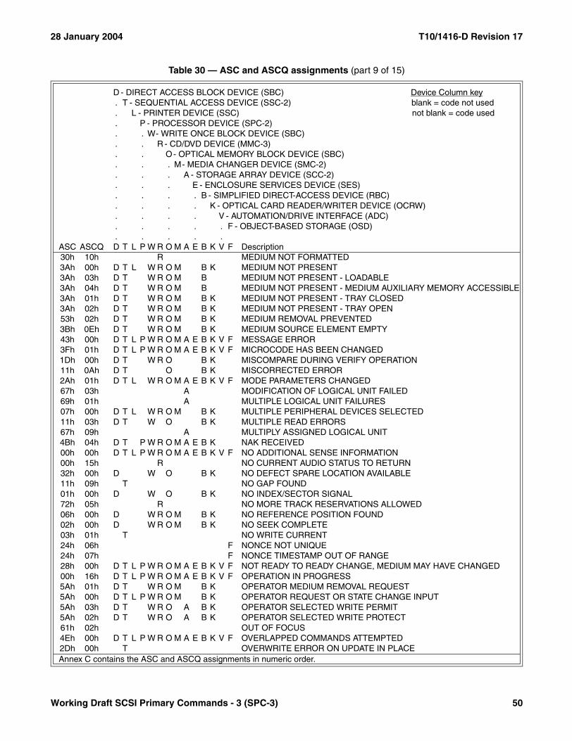
28 January 2004 T10/1416-D Revision 17
30h 10h R MEDIUM NOT FORMATTED3Ah 00h D T L W R O M B K MEDIUM NOT PRESENT3Ah 03h D T W R O M B MEDIUM NOT PRESENT - LOADABLE3Ah 04h D T W R O M B MEDIUM NOT PRESENT - MEDIUM AUXILIARY MEMORY ACCESSIBLE3Ah 01h D T W R O M B K MEDIUM NOT PRESENT - TRAY CLOSED3Ah 02h D T W R O M B K MEDIUM NOT PRESENT - TRAY OPEN53h 02h D T W R O M B K MEDIUM REMOVAL PREVENTED3Bh 0Eh D T W R O M B K MEDIUM SOURCE ELEMENT EMPTY43h 00h D T L P W R O M A E B K V F MESSAGE ERROR3Fh 01h D T L P W R O M A E B K V F MICROCODE HAS BEEN CHANGED1Dh 00h D T W R O B K MISCOMPARE DURING VERIFY OPERATION11h 0Ah D T O B K MISCORRECTED ERROR2Ah 01h D T L W R O M A E B K V F MODE PARAMETERS CHANGED67h 03h A MODIFICATION OF LOGICAL UNIT FAILED69h 01h A MULTIPLE LOGICAL UNIT FAILURES07h 00h D T L W R O M B K MULTIPLE PERIPHERAL DEVICES SELECTED11h 03h D T W O B K MULTIPLE READ ERRORS67h 09h A MULTIPLY ASSIGNED LOGICAL UNIT4Bh 04h D T P W R O M A E B K NAK RECEIVED00h 00h D T L P W R O M A E B K V F NO ADDITIONAL SENSE INFORMATION00h 15h R NO CURRENT AUDIO STATUS TO RETURN32h 00h D W O B K NO DEFECT SPARE LOCATION AVAILABLE11h 09h T NO GAP FOUND01h 00h D W O B K NO INDEX/SECTOR SIGNAL72h 05h R NO MORE TRACK RESERVATIONS ALLOWED06h 00h D W R O M B K NO REFERENCE POSITION FOUND02h 00h D W R O M B K NO SEEK COMPLETE03h 01h T NO WRITE CURRENT24h 06h F NONCE NOT UNIQUE24h 07h F NONCE TIMESTAMP OUT OF RANGE28h 00h D T L P W R O M A E B K V F NOT READY TO READY CHANGE, MEDIUM MAY HAVE CHANGED00h 16h D T L P W R O M A E B K V F OPERATION IN PROGRESS5Ah 01h D T W R O M B K OPERATOR MEDIUM REMOVAL REQUEST5Ah 00h D T L P W R O M B K OPERATOR REQUEST OR STATE CHANGE INPUT5Ah 03h D T W R O A B K OPERATOR SELECTED WRITE PERMIT5Ah 02h D T W R O A B K OPERATOR SELECTED WRITE PROTECT61h 02h OUT OF FOCUS4Eh 00h D T L P W R O M A E B K V F OVERLAPPED COMMANDS ATTEMPTED2Dh 00h T OVERWRITE ERROR ON UPDATE IN PLACE
Table 30 — ASC and ASCQ assignments (part 9 of 15)
D - DIRECT ACCESS BLOCK DEVICE (SBC) Device Column key. T - SEQUENTIAL ACCESS DEVICE (SSC-2) blank = code not used. L - PRINTER DEVICE (SSC) not blank = code used. P - PROCESSOR DEVICE (SPC-2). . W- WRITE ONCE BLOCK DEVICE (SBC). . R - CD/DVD DEVICE (MMC-3). . O- OPTICAL MEMORY BLOCK DEVICE (SBC). . . M- MEDIA CHANGER DEVICE (SMC-2). . . A - STORAGE ARRAY DEVICE (SCC-2). . . E - ENCLOSURE SERVICES DEVICE (SES). . . . B - SIMPLIFIED DIRECT-ACCESS DEVICE (RBC). . . . K - OPTICAL CARD READER/WRITER DEVICE (OCRW). . . . V - AUTOMATION/DRIVE INTERFACE (ADC). . . . . F - OBJECT-BASED STORAGE (OSD). . . . .
ASC ASCQ D T L P W R O M A E B K V F Description
Annex C contains the ASC and ASCQ assignments in numeric order.
Working Draft SCSI Primary Commands - 3 (SPC-3) 50
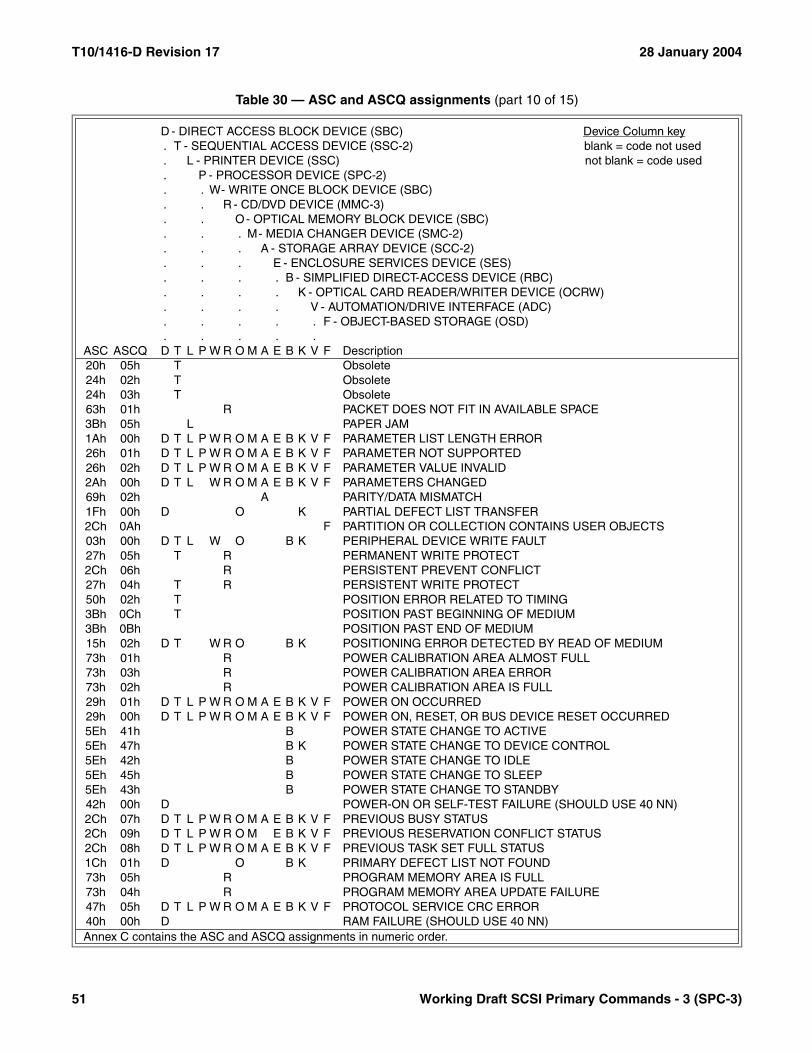
T10/1416-D Revision 17 28 January 2004
20h 05h T Obsolete24h 02h T Obsolete24h 03h T Obsolete63h 01h R PACKET DOES NOT FIT IN AVAILABLE SPACE3Bh 05h L PAPER JAM1Ah 00h D T L P W R O M A E B K V F PARAMETER LIST LENGTH ERROR26h 01h D T L P W R O M A E B K V F PARAMETER NOT SUPPORTED26h 02h D T L P W R O M A E B K V F PARAMETER VALUE INVALID2Ah 00h D T L W R O M A E B K V F PARAMETERS CHANGED69h 02h A PARITY/DATA MISMATCH1Fh 00h D O K PARTIAL DEFECT LIST TRANSFER2Ch 0Ah F PARTITION OR COLLECTION CONTAINS USER OBJECTS03h 00h D T L W O B K PERIPHERAL DEVICE WRITE FAULT27h 05h T R PERMANENT WRITE PROTECT2Ch 06h R PERSISTENT PREVENT CONFLICT27h 04h T R PERSISTENT WRITE PROTECT50h 02h T POSITION ERROR RELATED TO TIMING3Bh 0Ch T POSITION PAST BEGINNING OF MEDIUM3Bh 0Bh POSITION PAST END OF MEDIUM15h 02h D T W R O B K POSITIONING ERROR DETECTED BY READ OF MEDIUM73h 01h R POWER CALIBRATION AREA ALMOST FULL73h 03h R POWER CALIBRATION AREA ERROR73h 02h R POWER CALIBRATION AREA IS FULL29h 01h D T L P W R O M A E B K V F POWER ON OCCURRED29h 00h D T L P W R O M A E B K V F POWER ON, RESET, OR BUS DEVICE RESET OCCURRED5Eh 41h B POWER STATE CHANGE TO ACTIVE5Eh 47h B K POWER STATE CHANGE TO DEVICE CONTROL5Eh 42h B POWER STATE CHANGE TO IDLE5Eh 45h B POWER STATE CHANGE TO SLEEP5Eh 43h B POWER STATE CHANGE TO STANDBY42h 00h D POWER-ON OR SELF-TEST FAILURE (SHOULD USE 40 NN)2Ch 07h D T L P W R O M A E B K V F PREVIOUS BUSY STATUS2Ch 09h D T L P W R O M E B K V F PREVIOUS RESERVATION CONFLICT STATUS2Ch 08h D T L P W R O M A E B K V F PREVIOUS TASK SET FULL STATUS1Ch 01h D O B K PRIMARY DEFECT LIST NOT FOUND73h 05h R PROGRAM MEMORY AREA IS FULL73h 04h R PROGRAM MEMORY AREA UPDATE FAILURE47h 05h D T L P W R O M A E B K V F PROTOCOL SERVICE CRC ERROR40h 00h D RAM FAILURE (SHOULD USE 40 NN)
Table 30 — ASC and ASCQ assignments (part 10 of 15)
D - DIRECT ACCESS BLOCK DEVICE (SBC) Device Column key. T - SEQUENTIAL ACCESS DEVICE (SSC-2) blank = code not used. L - PRINTER DEVICE (SSC) not blank = code used. P - PROCESSOR DEVICE (SPC-2). . W- WRITE ONCE BLOCK DEVICE (SBC). . R - CD/DVD DEVICE (MMC-3). . O- OPTICAL MEMORY BLOCK DEVICE (SBC). . . M- MEDIA CHANGER DEVICE (SMC-2). . . A - STORAGE ARRAY DEVICE (SCC-2). . . E - ENCLOSURE SERVICES DEVICE (SES). . . . B - SIMPLIFIED DIRECT-ACCESS DEVICE (RBC). . . . K - OPTICAL CARD READER/WRITER DEVICE (OCRW). . . . V - AUTOMATION/DRIVE INTERFACE (ADC). . . . . F - OBJECT-BASED STORAGE (OSD). . . . .
ASC ASCQ D T L P W R O M A E B K V F Description
Annex C contains the ASC and ASCQ assignments in numeric order.
51 Working Draft SCSI Primary Commands - 3 (SPC-3)

28 January 2004 T10/1416-D Revision 17
15h 00h D T L W R O M B K RANDOM POSITIONING ERROR11h 13h D T L P W R O M A E B K V F READ ERROR - FAILED RETRANSMISSION REQUEST11h 11h R READ ERROR - LOSS OF STREAMING6Fh 03h R READ OF SCRAMBLED SECTOR WITHOUT AUTHENTICATION3Bh 0Ah READ PAST BEGINNING OF MEDIUM3Bh 09h READ PAST END OF MEDIUM3Bh 17h F READ PAST END OF USER OBJECT11h 01h D T W R O B K READ RETRIES EXHAUSTED6Ch 00h A REBUILD FAILURE OCCURRED6Dh 00h A RECALCULATE FAILURE OCCURRED14h 01h D T W R O B K RECORD NOT FOUND14h 06h D T W O B K RECORD NOT FOUND - DATA AUTO-REALLOCATED14h 05h D T W O B K RECORD NOT FOUND - RECOMMEND REASSIGNMENT14h 00h D T L W R O B K RECORDED ENTITY NOT FOUND18h 02h D W R O B K RECOVERED DATA - DATA AUTO-REALLOCATED18h 05h D W R O B K RECOVERED DATA - RECOMMEND REASSIGNMENT18h 06h D W R O B K RECOVERED DATA - RECOMMEND REWRITE17h 05h D W R O B K RECOVERED DATA USING PREVIOUS SECTOR ID18h 03h R RECOVERED DATA WITH CIRC18h 07h D W O B K RECOVERED DATA WITH ECC - DATA REWRITTEN18h 01h D W R O B K RECOVERED DATA WITH ERROR CORR. & RETRIES APPLIED18h 00h D T W R O B K RECOVERED DATA WITH ERROR CORRECTION APPLIED18h 04h R RECOVERED DATA WITH L-EC18h 08h R RECOVERED DATA WITH LINKING17h 03h D T W R O B K RECOVERED DATA WITH NEGATIVE HEAD OFFSET17h 00h D T W R O B K RECOVERED DATA WITH NO ERROR CORRECTION APPLIED17h 02h D T W R O B K RECOVERED DATA WITH POSITIVE HEAD OFFSET17h 01h D T W R O B K RECOVERED DATA WITH RETRIES17h 04h W R O B RECOVERED DATA WITH RETRIES AND/OR CIRC APPLIED17h 06h D W O B K RECOVERED DATA WITHOUT ECC - DATA AUTO-REALLOCATED17h 09h D W R O B K RECOVERED DATA WITHOUT ECC - DATA REWRITTEN17h 07h D W R O B K RECOVERED DATA WITHOUT ECC - RECOMMEND REASSIGNMENT17h 08h D W R O B K RECOVERED DATA WITHOUT ECC - RECOMMEND REWRITE1Eh 00h D W O B K RECOVERED ID WITH ECC CORRECTION3Fh 06h D T W R O M A E B REDUNDANCY GROUP CREATED OR MODIFIED3Fh 07h D T W R O M A E B REDUNDANCY GROUP DELETED6Bh 01h A REDUNDANCY LEVEL GOT BETTER6Bh 02h A REDUNDANCY LEVEL GOT WORSE2Ah 05h D T L P W R O M A E REGISTRATIONS PREEMPTED
Table 30 — ASC and ASCQ assignments (part 11 of 15)
D - DIRECT ACCESS BLOCK DEVICE (SBC) Device Column key. T - SEQUENTIAL ACCESS DEVICE (SSC-2) blank = code not used. L - PRINTER DEVICE (SSC) not blank = code used. P - PROCESSOR DEVICE (SPC-2). . W- WRITE ONCE BLOCK DEVICE (SBC). . R - CD/DVD DEVICE (MMC-3). . O- OPTICAL MEMORY BLOCK DEVICE (SBC). . . M- MEDIA CHANGER DEVICE (SMC-2). . . A - STORAGE ARRAY DEVICE (SCC-2). . . E - ENCLOSURE SERVICES DEVICE (SES). . . . B - SIMPLIFIED DIRECT-ACCESS DEVICE (RBC). . . . K - OPTICAL CARD READER/WRITER DEVICE (OCRW). . . . V - AUTOMATION/DRIVE INTERFACE (ADC). . . . . F - OBJECT-BASED STORAGE (OSD). . . . .
ASC ASCQ D T L P W R O M A E B K V F Description
Annex C contains the ASC and ASCQ assignments in numeric order.
Working Draft SCSI Primary Commands - 3 (SPC-3) 52

T10/1416-D Revision 17 28 January 2004
67h 05h A REMOVE OF LOGICAL UNIT FAILED3Fh 0Eh D T L P W R O M A E REPORTED LUNS DATA HAS CHANGED3Bh 08h T REPOSITION ERROR2Ah 03h D T L P W R O M A E K RESERVATIONS PREEMPTED2Ah 04h D T L P W R O M A E RESERVATIONS RELEASED00h 1Ah T REWIND OPERATION IN PROGRESS36h 00h L RIBBON, INK, OR TONER FAILURE73h 06h R RMA/PMA IS ALMOST FULL37h 00h D T L W R O M A E B K V F ROUNDED PARAMETER5Ch 00h D O RPL STATUS CHANGE39h 00h D T L W R O M A E K SAVING PARAMETERS NOT SUPPORTED62h 00h SCAN HEAD POSITIONING ERROR29h 02h D T L P W R O M A E B K V F SCSI BUS RESET OCCURRED47h 00h D T L P W R O M A E B K V F SCSI PARITY ERROR47h 02h D T L P W R O M A E B K V F SCSI PARITY ERROR DETECTED DURING ST DATA PHASE54h 00h P SCSI TO HOST SYSTEM INTERFACE FAILURE24h 04h F SECURITY AUDIT VALUE FROZEN24h 05h F SECURITY WORKING KEY FROZEN45h 00h D T L P W R O M A E B K V F SELECT OR RESELECT FAILURE3Bh 00h T L SEQUENTIAL POSITIONING ERROR5Dh 45h D B SERVO IMPENDING FAILURE ACCESS TIMES TOO HIGH5Dh 47h D B SERVO IMPENDING FAILURE CHANNEL PARAMETRICS5Dh 48h D B SERVO IMPENDING FAILURE CONTROLLER DETECTED5Dh 42h D B SERVO IMPENDING FAILURE DATA ERROR RATE TOO HIGH5Dh 4Ch D B SERVO IMPENDING FAILURE DRIVE CALIBRATION RETRY COUNT5Dh 41h D B SERVO IMPENDING FAILURE DRIVE ERROR RATE TOO HIGH5Dh 40h D B SERVO IMPENDING FAILURE GENERAL HARD DRIVE FAILURE5Dh 43h D B SERVO IMPENDING FAILURE SEEK ERROR RATE TOO HIGH5Dh 4Ah D B SERVO IMPENDING FAILURE SEEK TIME PERFORMANCE5Dh 4Bh D B SERVO IMPENDING FAILURE SPIN-UP RETRY COUNT5Dh 46h D B SERVO IMPENDING FAILURE START UNIT TIMES TOO HIGH5Dh 49h D B SERVO IMPENDING FAILURE THROUGHPUT PERFORMANCE5Dh 44h D B SERVO IMPENDING FAILURE TOO MANY BLOCK REASSIGNS72h 00h R SESSION FIXATION ERROR72h 03h R SESSION FIXATION ERROR - INCOMPLETE TRACK IN SESSION72h 01h R SESSION FIXATION ERROR WRITING LEAD-IN72h 02h R SESSION FIXATION ERROR WRITING LEAD-OUT00h 1Bh T SET CAPACITY OPERATION IN PROGRESS67h 0Ah D T L P W R O M A E B K V F SET TARGET PORT GROUPS COMMAND FAILED
Table 30 — ASC and ASCQ assignments (part 12 of 15)
D - DIRECT ACCESS BLOCK DEVICE (SBC) Device Column key. T - SEQUENTIAL ACCESS DEVICE (SSC-2) blank = code not used. L - PRINTER DEVICE (SSC) not blank = code used. P - PROCESSOR DEVICE (SPC-2). . W- WRITE ONCE BLOCK DEVICE (SBC). . R - CD/DVD DEVICE (MMC-3). . O- OPTICAL MEMORY BLOCK DEVICE (SBC). . . M- MEDIA CHANGER DEVICE (SMC-2). . . A - STORAGE ARRAY DEVICE (SCC-2). . . E - ENCLOSURE SERVICES DEVICE (SES). . . . B - SIMPLIFIED DIRECT-ACCESS DEVICE (RBC). . . . K - OPTICAL CARD READER/WRITER DEVICE (OCRW). . . . V - AUTOMATION/DRIVE INTERFACE (ADC). . . . . F - OBJECT-BASED STORAGE (OSD). . . . .
ASC ASCQ D T L P W R O M A E B K V F Description
Annex C contains the ASC and ASCQ assignments in numeric order.
53 Working Draft SCSI Primary Commands - 3 (SPC-3)

28 January 2004 T10/1416-D Revision 17
00h 03h T SETMARK DETECTED3Bh 04h L SLEW FAILURE47h 7Fh D T P W R O M A E B K SOME COMMANDS CLEARED BY ISCSI PROTOCOL EVENT5Dh 03h R SPARE AREA EXHAUSTION PREDICTION THRESHOLD EXCEEDED3Fh 08h D T W R O M A E B SPARE CREATED OR MODIFIED3Fh 09h D T W R O M A E B SPARE DELETED5Dh 55h D B SPINDLE IMPENDING FAILURE ACCESS TIMES TOO HIGH5Dh 57h D B SPINDLE IMPENDING FAILURE CHANNEL PARAMETRICS5Dh 58h D B SPINDLE IMPENDING FAILURE CONTROLLER DETECTED5Dh 52h D B SPINDLE IMPENDING FAILURE DATA ERROR RATE TOO HIGH5Dh 5Ch D B SPINDLE IMPENDING FAILURE DRIVE CALIBRATION RETRY COUNT5Dh 51h D B SPINDLE IMPENDING FAILURE DRIVE ERROR RATE TOO HIGH5Dh 50h D B SPINDLE IMPENDING FAILURE GENERAL HARD DRIVE FAILURE5Dh 53h D B SPINDLE IMPENDING FAILURE SEEK ERROR RATE TOO HIGH5Dh 5Ah D B SPINDLE IMPENDING FAILURE SEEK TIME PERFORMANCE5Dh 5Bh D B SPINDLE IMPENDING FAILURE SPIN-UP RETRY COUNT5Dh 56h D B SPINDLE IMPENDING FAILURE START UNIT TIMES TOO HIGH5Dh 59h D B SPINDLE IMPENDING FAILURE THROUGHPUT PERFORMANCE5Dh 54h D B SPINDLE IMPENDING FAILURE TOO MANY BLOCK REASSIGNS09h 03h W R O SPINDLE SERVO FAILURE5Ch 02h D O SPINDLES NOT SYNCHRONIZED5Ch 01h D O SPINDLES SYNCHRONIZED5Eh 04h D T L P W R O A K STANDBY CONDITION ACTIVATED BY COMMAND5Eh 02h D T L P W R O A K STANDBY CONDITION ACTIVATED BY TIMER6Bh 00h A STATE CHANGE HAS OCCURRED1Bh 00h D T L P W R O M A E B K V F SYNCHRONOUS DATA TRANSFER ERROR55h 01h D O B K SYSTEM BUFFER FULL55h 00h P SYSTEM RESOURCE FAILURE4Dh NNh D T L P W R O M A E B K V F TAGGED OVERLAPPED COMMANDS (NN = TASK TAG)33h 00h T TAPE LENGTH ERROR3Bh 03h L TAPE OR ELECTRONIC VERTICAL FORMS UNIT NOT READY3Bh 01h T TAPE POSITION ERROR AT BEGINNING-OF-MEDIUM3Bh 02h T TAPE POSITION ERROR AT END-OF-MEDIUM3Fh 00h D T L P W R O M A E B K V F TARGET OPERATING CONDITIONS HAVE CHANGED0Dh 01h D T L P W R O A K THIRD PARTY DEVICE FAILURE5Bh 01h D T L P W R O M K THRESHOLD CONDITION MET26h 03h D T L P W R O M A E K THRESHOLD PARAMETERS NOT SUPPORTED3Eh 02h D T L P W R O M A E B K V F TIMEOUT ON LOGICAL UNIT26h 08h D T L P W R O K TOO MANY SEGMENT DESCRIPTORS
Table 30 — ASC and ASCQ assignments (part 13 of 15)
D - DIRECT ACCESS BLOCK DEVICE (SBC) Device Column key. T - SEQUENTIAL ACCESS DEVICE (SSC-2) blank = code not used. L - PRINTER DEVICE (SSC) not blank = code used. P - PROCESSOR DEVICE (SPC-2). . W- WRITE ONCE BLOCK DEVICE (SBC). . R - CD/DVD DEVICE (MMC-3). . O- OPTICAL MEMORY BLOCK DEVICE (SBC). . . M- MEDIA CHANGER DEVICE (SMC-2). . . A - STORAGE ARRAY DEVICE (SCC-2). . . E - ENCLOSURE SERVICES DEVICE (SES). . . . B - SIMPLIFIED DIRECT-ACCESS DEVICE (RBC). . . . K - OPTICAL CARD READER/WRITER DEVICE (OCRW). . . . V - AUTOMATION/DRIVE INTERFACE (ADC). . . . . F - OBJECT-BASED STORAGE (OSD). . . . .
ASC ASCQ D T L P W R O M A E B K V F Description
Annex C contains the ASC and ASCQ assignments in numeric order.
Working Draft SCSI Primary Commands - 3 (SPC-3) 54
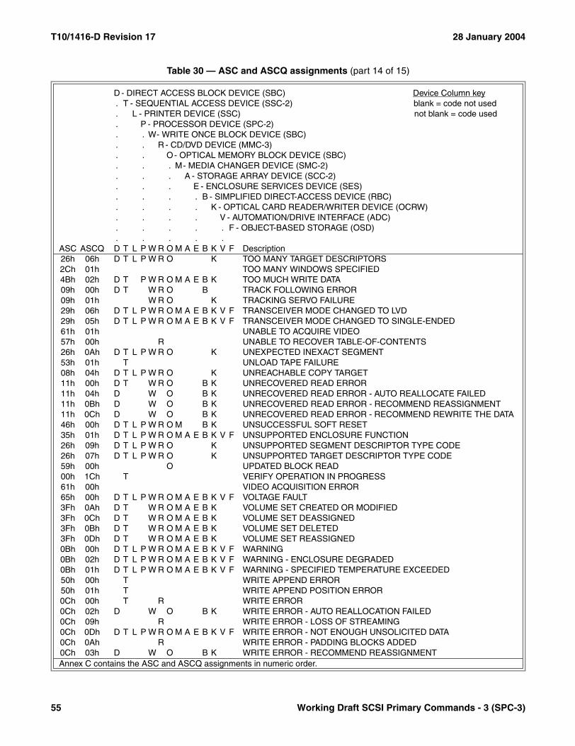
T10/1416-D Revision 17 28 January 2004
26h 06h D T L P W R O K TOO MANY TARGET DESCRIPTORS2Ch 01h TOO MANY WINDOWS SPECIFIED4Bh 02h D T P W R O M A E B K TOO MUCH WRITE DATA09h 00h D T W R O B TRACK FOLLOWING ERROR09h 01h W R O K TRACKING SERVO FAILURE29h 06h D T L P W R O M A E B K V F TRANSCEIVER MODE CHANGED TO LVD29h 05h D T L P W R O M A E B K V F TRANSCEIVER MODE CHANGED TO SINGLE-ENDED61h 01h UNABLE TO ACQUIRE VIDEO57h 00h R UNABLE TO RECOVER TABLE-OF-CONTENTS26h 0Ah D T L P W R O K UNEXPECTED INEXACT SEGMENT53h 01h T UNLOAD TAPE FAILURE08h 04h D T L P W R O K UNREACHABLE COPY TARGET11h 00h D T W R O B K UNRECOVERED READ ERROR11h 04h D W O B K UNRECOVERED READ ERROR - AUTO REALLOCATE FAILED11h 0Bh D W O B K UNRECOVERED READ ERROR - RECOMMEND REASSIGNMENT11h 0Ch D W O B K UNRECOVERED READ ERROR - RECOMMEND REWRITE THE DATA46h 00h D T L P W R O M B K UNSUCCESSFUL SOFT RESET35h 01h D T L P W R O M A E B K V F UNSUPPORTED ENCLOSURE FUNCTION26h 09h D T L P W R O K UNSUPPORTED SEGMENT DESCRIPTOR TYPE CODE26h 07h D T L P W R O K UNSUPPORTED TARGET DESCRIPTOR TYPE CODE59h 00h O UPDATED BLOCK READ00h 1Ch T VERIFY OPERATION IN PROGRESS61h 00h VIDEO ACQUISITION ERROR65h 00h D T L P W R O M A E B K V F VOLTAGE FAULT3Fh 0Ah D T W R O M A E B K VOLUME SET CREATED OR MODIFIED3Fh 0Ch D T W R O M A E B K VOLUME SET DEASSIGNED3Fh 0Bh D T W R O M A E B K VOLUME SET DELETED3Fh 0Dh D T W R O M A E B K VOLUME SET REASSIGNED0Bh 00h D T L P W R O M A E B K V F WARNING0Bh 02h D T L P W R O M A E B K V F WARNING - ENCLOSURE DEGRADED0Bh 01h D T L P W R O M A E B K V F WARNING - SPECIFIED TEMPERATURE EXCEEDED50h 00h T WRITE APPEND ERROR50h 01h T WRITE APPEND POSITION ERROR0Ch 00h T R WRITE ERROR0Ch 02h D W O B K WRITE ERROR - AUTO REALLOCATION FAILED0Ch 09h R WRITE ERROR - LOSS OF STREAMING0Ch 0Dh D T L P W R O M A E B K V F WRITE ERROR - NOT ENOUGH UNSOLICITED DATA0Ch 0Ah R WRITE ERROR - PADDING BLOCKS ADDED0Ch 03h D W O B K WRITE ERROR - RECOMMEND REASSIGNMENT
Table 30 — ASC and ASCQ assignments (part 14 of 15)
D - DIRECT ACCESS BLOCK DEVICE (SBC) Device Column key. T - SEQUENTIAL ACCESS DEVICE (SSC-2) blank = code not used. L - PRINTER DEVICE (SSC) not blank = code used. P - PROCESSOR DEVICE (SPC-2). . W- WRITE ONCE BLOCK DEVICE (SBC). . R - CD/DVD DEVICE (MMC-3). . O- OPTICAL MEMORY BLOCK DEVICE (SBC). . . M- MEDIA CHANGER DEVICE (SMC-2). . . A - STORAGE ARRAY DEVICE (SCC-2). . . E - ENCLOSURE SERVICES DEVICE (SES). . . . B - SIMPLIFIED DIRECT-ACCESS DEVICE (RBC). . . . K - OPTICAL CARD READER/WRITER DEVICE (OCRW). . . . V - AUTOMATION/DRIVE INTERFACE (ADC). . . . . F - OBJECT-BASED STORAGE (OSD). . . . .
ASC ASCQ D T L P W R O M A E B K V F Description
Annex C contains the ASC and ASCQ assignments in numeric order.
55 Working Draft SCSI Primary Commands - 3 (SPC-3)

28 January 2004 T10/1416-D Revision 17
0Ch 01h K WRITE ERROR - RECOVERED WITH AUTO REALLOCATION0Ch 08h R WRITE ERROR - RECOVERY FAILED0Ch 07h R WRITE ERROR - RECOVERY NEEDED0Ch 0Ch D T L P W R O M A E B K V F WRITE ERROR - UNEXPECTED UNSOLICITED DATA27h 00h D T W R O B K WRITE PROTECTED31h 02h R ZONED FORMATTING FAILED DUE TO SPARE LINKING
80h xxh \Through > Vendor specific.
FFh xxh /
xxh 80h \Through > Vendor specific QUALIFICATION OF STANDARD ASC.
xxh FFh /ALL CODES NOT SHOWN ARE RESERVED.
Table 30 — ASC and ASCQ assignments (part 15 of 15)
D - DIRECT ACCESS BLOCK DEVICE (SBC) Device Column key. T - SEQUENTIAL ACCESS DEVICE (SSC-2) blank = code not used. L - PRINTER DEVICE (SSC) not blank = code used. P - PROCESSOR DEVICE (SPC-2). . W- WRITE ONCE BLOCK DEVICE (SBC). . R - CD/DVD DEVICE (MMC-3). . O- OPTICAL MEMORY BLOCK DEVICE (SBC). . . M- MEDIA CHANGER DEVICE (SMC-2). . . A - STORAGE ARRAY DEVICE (SCC-2). . . E - ENCLOSURE SERVICES DEVICE (SES). . . . B - SIMPLIFIED DIRECT-ACCESS DEVICE (RBC). . . . K - OPTICAL CARD READER/WRITER DEVICE (OCRW). . . . V - AUTOMATION/DRIVE INTERFACE (ADC). . . . . F - OBJECT-BASED STORAGE (OSD). . . . .
ASC ASCQ D T L P W R O M A E B K V F Description
Annex C contains the ASC and ASCQ assignments in numeric order.
Working Draft SCSI Primary Commands - 3 (SPC-3) 56

T10/1416-D Revision 17 28 January 2004
5 Model common to all device types
5.1 Introduction to the model common to all device types
This model describes some of the general characteristics expected of most SCSI devices. It is not intended to alterany requirements defined elsewhere in SCSI. Devices conforming to this standard also shall conform to SAM-2.
5.2 Commands implemented by all SCSI device servers
5.2.1 Summary of commands implemented by all SCSI device servers
This standard defines three commands that all SCSI device servers shall implement - INQUIRY, REQUESTSENSE, and TEST UNIT READY. These commands are used to configure the system, to test devices, and toreturn important information concerning errors and exception conditions.
5.2.2 Using the INQUIRY command
The INQUIRY command may be used by an application client to determine the configuration of the logical unit.Device servers respond with information that includes their type and standard version and may include the vendor'sidentification, model number and other information. It is recommended that device servers be capable of returningthis information (or whatever part of it that is available) upon completing power-on initialization. A device servermay take longer to get certain portions of this information, especially if it retrieves the information from the medium.
5.2.3 Using the REQUEST SENSE command
The REQUEST SENSE command may be used by an application client to poll the status of some backgroundoperations and to clear interlocked unit attention conditions (see 7.4.6).
5.2.4 Using the TEST UNIT READY command
The TEST UNIT READY command allows an application client to poll a logical unit until it is ready without the needto allocate space for returned data. The TEST UNIT READY command may be used to check the media status oflogical units with removable media. Device servers should respond promptly to indicate the current status of theSCSI device, delays to achieve GOOD status may adversely affect initiator performance.
5.3 Implicit head of queue
The following commands may be processed by the task manager as if they have a task attribute of HEAD OF QUEUE
(see SAM-3) if they are received with a SIMPLE task attribute, an ORDERED task attribute, or no task attribute:
a) INQUIRY; andb) REPORT LUNS.
57 Working Draft SCSI Primary Commands - 3 (SPC-3)
28 January 2004 T10/1416-D Revision 17
5.4 Parameter rounding
Certain parameters sent to a device server with various commands contain a range of values. Device servers maychoose to implement only selected values from this range. When the device server receives a value that it does notsupport, it either rejects the command (CHECK CONDITION status with ILLEGAL REQUEST sense key) or itrounds the value received to a supported value.
When parameter rounding is implemented, a device server that receives a parameter value that is not an exactsupported value shall adjust the value to one that it supports and shall return CHECK CONDITION status with asense key of RECOVERED ERROR. The additional sense code shall be set to ROUNDED PARAMETER. Theapplication client should issue an appropriate command to learn what value the device server has selected.
The device server shall reject unsupported values unless rounding is permitted in the description of the parameter.When the description of a parameter states that rounding is permitted, the device server should adjustmaximum-value fields down to the next lower supported value than the one specified by the application client.Minimum-value fields should be rounded up to the next higher supported value than the one specified by the appli-cation client. In some cases, the type of rounding (up or down) is explicitly specified in the description of theparameter.
5.5 Self-test operations
5.5.1 Default self-test
The SEND DIAGNOSTIC command provides a means to request that a SCSI device perform a self test. While thetest is vendor specific, the means of requesting the test is standardized.
The default self-test is mandatory for all device types that support the SEND DIAGNOSTIC command. Theresponse is GOOD status if the test detects no exceptions or a CHECK CONDITION status if the test detectsexceptions.
5.5.2 The short and extended self-tests
There are two optional types of self-test aside from the mandatory default self-test that may be invoked using theSELF-TEST CODE field in the SEND DIAGNOSTIC command: a short self-test and an extended self-test. The goal ofthe short self-test is to quickly identify if the logical unit determines that it is faulty. A goal of the extended self-testroutine is to simplify factory testing during integration by having logical units perform more comprehensive testingwithout application client intervention. A second goal of the extended self-test is to provide a more comprehensivetest to validate the results of a short self-test, if its results are judged by the application client to be inconclusive.
The criteria for the short self-test are that it has one or more segments and completes in two minutes or less. Thecriteria for the extended self-test are that it is has one or more segments and that the completion time is vendorspecific. Any tests performed in the segments are vendor specific.
The following are examples of segments:
a) An electrical segment wherein the logical unit tests its own electronics. The tests in this segment arevendor specific, but some examples of tests that may be included are: a buffer RAM test, a read/writecircuitry test, and/or a test of the read/write heads;
b) A seek/servo segment wherein a device tests it capability to find and servo on data tracks; andc) A read/verify scan segment wherein a device performs read scanning of some or all of the medium
surface.
Working Draft SCSI Primary Commands - 3 (SPC-3) 58

T10/1416-D Revision 17 28 January 2004
The tests performed in the segments may be the same for the short and extended self-tests. The time required bya logical unit to complete its extended self-test is reported in the EXTENDED SELF-TEST COMPLETION TIME field in theControl mode page (see 7.4.6).
5.5.3 Self-test modes
There are two modes for short and extended self-tests: a foreground mode and a background mode. These modesare described in 5.5.3.1 and 5.5.3.2.
5.5.3.1 Foreground mode
When a device server receives a SEND DIAGNOSTIC command specifying a self-test to be performed in theforeground mode, the device server shall return status for that command after the self-test has been completed.
While performing a self-test in the foreground mode, the device server shall respond to all commands exceptINQUIRY, REPORT LUNS, and REQUEST SENSE with a CHECK CONDITION status, a sense key of NOTREADY and an additional sense code of LOGICAL UNIT NOT READY, SELF-TEST IN PROGRESS.
If a device server is performing a self-test in the foreground mode and a test segment error occurs during the test,the device server shall update the Self-Test Results log page (see 7.2.10) and report CHECK CONDITION statuswith a sense key of HARDWARE ERROR and an additional sense code of LOGICAL UNIT FAILED SELF-TEST.The application client may obtain additional information about the failure by reading the Self-Test Results log page.If the device server is unable to update the Self-Test Results log page it shall return a CHECK CONDITION statuswith a sense key of HARDWARE ERROR and an additional sense code of LOGICAL UNIT UNABLE TO UPDATESELF-TEST LOG.
An application client should reserve the logical unit before initiating a self-test in the foreground mode. An appli-cation client may terminate a self-test that is being performed in the foreground mode using an ABORT TASK,ABORT TASK SET, or CLEAR TASK SET task management function. If a task manager receives an ABORT TASK,ABORT TASK SET, or CLEAR TASK SET task management function while performing a self-test in the foregroundmode, then it shall abort the self-test and update the Self-Test Results log page (see 7.2.10).
5.5.3.2 Background mode
When a device server receives a SEND DIAGNOSTIC command specifying a self-test to be performed in thebackground mode, the device server shall return status for that command as soon as the CDB has been validated.
After returning status for the SEND DIAGNOSTIC command specifying a self-test to be performed in thebackground mode, the device server shall initialize the Self-Test Results log page (see 7.2.10) as follows. Theself-test code from the SEND DIAGNOSTIC command shall be placed in the SELF-TEST CODE field in the log page.The SELF-TEST RESULTS field shall be set to Fh. After the Self-Test Results log page is initialized, the device servershall begin the first self-test segment.
While the device server is performing a self-test in the background mode, it shall terminate with a CHECKCONDITION status any SEND DIAGNOSTIC command it receives that meets one of the following criteria:
a) The SELFTEST bit is set to one; orb) The SELF-TEST CODE field contains a value other than 000b or 100b.
When terminating the SEND DIAGNOSTIC command, the sense key shall be set to NOT READY and theadditional sense code shall be set to LOGICAL UNIT NOT READY, SELF-TEST IN PROGRESS.
59 Working Draft SCSI Primary Commands - 3 (SPC-3)

28 January 2004 T10/1416-D Revision 17
While performing a self-test in the background mode, the device server shall suspend the self-test to service anyother commands received with the exceptions listed in table 31. Suspension of the self-test to service thecommand shall occur as soon as practical and shall not take longer than two seconds.
If one of the exception commands listed in table 31 is received, the device server shall abort the self-test, updatethe self-test log, and service the command as soon as practical but not longer than two seconds after the CDB hasbeen validated.
An application client may terminate a self-test that is being performed in the background mode by issuing a SENDDIAGNOSTIC command with the SELF-TEST CODE field set to 100b (Abort background self-test function).
5.5.3.3 Features common to foreground and background self-test modes
The PROGRESS INDICATION field returned in response to a REQUEST SENSE command (see 6.25) may be used bythe application client at any time during a self-test operation to poll the logical unit’s progress. While a self-testoperation is in progress unless an error has occurred, a device server shall respond to a REQUEST SENSEcommand by returning a sense key of NOT READY and an additional sense code of LOGICAL UNIT NOT READY,SELF-TEST IN PROGRESS with the sense key specific bytes set for progress indication.
The application client may obtain information about the twenty most recently completed self-tests by reading theSelf-Test Results log page (see 7.2.10). This is the only method for an application client to obtain information aboutself-tests performed in the background mode.
Table 31 — Exception commands for background self-tests
Device type Command Reference
All device typesSEND DIAGNOSTIC (with SELF-TEST CODE field set to 100b)WRITE BUFFER (with the mode set to any download microcode option)
6.266.31
Direct access FORMAT UNIT START STOP UNIT SBC
Sequential access
ERASEFORMAT MEDIUMLOAD UNLOADLOCATEREADREAD POSITIONREAD REVERSE
REWINDSPACEVERIFYWRITEWRITE BUFFERWRITE FILEMARKS
SSC-2
Medium changer
EXCHANGE MEDIUMINITIALIZE ELEMENT STATUSMOVE MEDIUMPOSITION TO ELEMENTREAD ELEMENT STATUS (if CURDATA=0 and device motion is required)WRITE BUFFER
SMC
NOTE 1 Device types not listed in this table do not have commands that are exceptions for background self-tests, other than those listed above for all device types.
Working Draft SCSI Primary Commands - 3 (SPC-3) 60

T10/1416-D Revision 17 28 January 2004
Table 32 summarizes when a logical unit returns status after receipt of a self-test command, how an applicationclient may abort a self-test, how a logical unit handles new commands that are received while a self-test is inprogress, and how a logical unit reports a self-test failure.
5.6 Reservations
5.6.1 Persistent Reservations overview
Reservations may be used to allow a device server to process commands from a selected set of I_T nexuses (i.e.,combinations of initiator ports accessing target ports) and reject commands from I_T nexuses outside the selectedset. The device server uniquely identifies I_T nexuses using protocol specific mechanisms.
Application clients may add or remove I_T nexuses from the selected set using reservation commands. If the appli-cation clients do not cooperate in the reservation protocol, data may be unexpectedly modified and deadlock condi-tions may occur.
The persistent reservations mechanism allows multiple application clients communicating through multiple I_Tnexuses to protect reservation operations across SCSI initiator device failures, which usually involve logical unitresets and involve I_T nexus losses. Persistent reservations persist across recovery actions, to provide applicationclients with more detailed control over reservations recovery. Persistent reservations are not reset by hard reset,logical unit reset, or I_T nexus loss.
The persistent reservation held by a failing I_T nexus may be preempted by another I_T nexus as part of therecovery process. Persistent reservations shall be retained by the device server until released, preempted, orcleared by mechanisms specified in this standard. Optionally, persistent reservations may be retained when powerto the target is removed.
The PERSISTENT RESERVE OUT and PERSISTENT RESERVE IN commands provide the basic mechanism fordynamic contention resolution in systems with multiple initiator ports using logical units with SCSI 3 multiple targetports.
Table 32 — Self-test mode summary
Mode
When Status is Returned
How to abort the self-test
Processing of subsequent commands while self-test is
executing Self-test failure reporting
Fore-ground
After the self-test is complete
ABORT TASK task manage-ment function
If the command is INQUIRY, REPORT LUNS or REQUEST SENSE, process normally. Otherwise, terminate with CHECK CONDITION status, NOT READY sense key, and LOGICAL UNIT NOT READY, SELF-TEST IN PROGRESS additional sense code.
Terminate with CHECK CONDI-TION status, HARDWARE ERROR sense key, and LOGI-CAL UNIT FAILED SELF-TEST or LOGICAL UNIT UNABLE TO UPDATE SELF-TEST LOG addi-tional sense code.
Back-ground
After the CDB is validated
SEND DIAG-NOSTIC command with SELF-TEST CODE field set to 100b
Process the command, except as described in 5.5.3.2.
Application client checks Self-Test Results log page (see 7.2.10) after the PROGRESS INDICATION field returned from REQUEST SENSE indicates the self-test is complete.
61 Working Draft SCSI Primary Commands - 3 (SPC-3)
28 January 2004 T10/1416-D Revision 17
Before a persistent reservation may be established, an application client shall register each I_T nexus with a deviceserver using a reservation key. Reservation keys are necessary to allow:
a) Authentication of subsequent PERSISTENT RESERVE OUT commands;b) Identification of other I_T nexuses that are registered;c) Identification of the reservation key(s) that have an associated persistent reservation;d) Preemption of a persistent reservation from a failing or uncooperative I_T nexus; ande) Multiple I_T nexuses to participate in a persistent reservation.
The reservation key provides a method for the application client to associate a protocol-independent identifier witha registered I_T nexus. The reservation key is used in the PERSISTENT RESERVE IN command to identify whichI_T nexuses are registered and which I_T nexus, if any, holds the persistent reservation. The reservation key isused in the PERSISTENT RESERVE OUT command to register an I_T nexus, to verify the I_T nexus being usedfor the PERSISTENT RESERVATION OUT command is registered, and to specify which registrations or persistentreservation to preempt.
Reservation key values may be used by application clients to identify registered I_T nexuses, using applicationspecific methods that are outside the scope of this standard. This standard provides the ability to register no morethan one reservation key per I_T nexus. Multiple I_T nexuses may use the same reservation key for a logical unitaccessed through the same target port. Multiple initiator ports may use the same reservation key value for a logicalunit accessed through the same target ports. An initiator port may use the same reservation key value for a logicalunit accessed through different target ports. The logical unit shall maintain a separate reservation key for each I_Tnexus, regardless of the reservation key’s value.
An application client may register an I_T nexus with multiple logical units in a SCSI target device using any combi-nation of unique or duplicate reservation keys. These rules provide the ability for an application client to preemptmultiple I_T nexuses with a single PERSISTENT RESERVE OUT command, but they do not provide the ability forthe application client to uniquely identify the I_T nexuses using the PERSISTENT RESERVE commands.
See table 106 in 6.12.2 for a list of PERSISTENT RESERVE OUT service actions. See table 97 in 6.11.2.1 for a listof PERSISTENT RESERVE IN service actions.
The scope of a persistent reservation shall be the entire logical unit.
Persistent reservations may be further qualified by restrictions on types of access (e.g., read, write). However, anyrestrictions based on the type of reservation are independent of the scope of the reservation.
Reservation restrictions are placed on commands as a result of access qualifiers associated with the type of reser-vation. The details of which commands are allowed under what types of reservations are described in table 33.
In table 33 and table 34 the following key words are used:
allowed: Commands received from I_T nexuses not holding the reservation or from I_T nexuses not registeredwhen a registrants only or all registrants type persistent reservation is present should complete normally.
conflict: Commands received from I_T nexuses not holding the reservation or from I_T nexuses not registeredwhen a registrants only or all registrants type persistent reservation is present shall not be performed and thedevice server shall terminate the command with a RESERVATION CONFLICT status.
Commands from I_T nexuses holding a reservation should complete normally. The behavior of commands fromregistered I_T nexuses when a registrants only or all registrants type persistent reservation is present is specifiedin table 33 and table 34.
Working Draft SCSI Primary Commands - 3 (SPC-3) 62

T10/1416-D Revision 17 28 January 2004
An unlinked command shall be checked for reservation conflicts before the task containing that command entersthe enabled task state. The reservation state as it exists when the first command in a group of linked commandsenters the enabled task state shall be used in checking for reservation conflicts for all the commands in the task.Once a task has entered the enabled task state, the command or commands comprising that task shall not beterminated with a RESERVATION CONFLICT due to a subsequent reservation. Any command in a group of linkedcommands that changes the reservation state shall be the last command in the group.
For each command, this standard or other command standard (see 3.1.17) defines the conditions that result inRESERVATION CONFLICT. Command standards define the conditions either in the device model (preferred) or inthe descriptions each specific command.
Table 33 — SPC commands that are allowed in the presence of various reservations (part 1 of 2)
Command
Addressed LU has this type of persistent reservation held by another I_T nexus
From any I_T nexus
From registered I_T nexus
(RR all types)
From I_T nexus not registered
Write Excl
Excl Access
Write Excl RR
Excl Acc- ess – RR
ACCESS CONTROL IN Allowed Allowed Allowed Allowed Allowed
ACCESS CONTROL OUT Allowed Allowed Allowed Allowed Allowed
CHANGE ALIASES Conflict Conflict Allowed Conflict Conflict
EXTENDED COPY Conflict Conflict Allowed Conflict Conflict
INQUIRY Allowed Allowed Allowed Allowed Allowed
LOG SELECT Conflict Conflict Allowed Conflict Conflict
LOG SENSE Allowed Allowed Allowed Allowed Allowed
MODE SELECT(6)/MODE SELECT(10)
Conflict Conflict Allowed Conflict Conflict
MODE SENSE(6)/MODE SENSE(10)
Conflict Conflict Allowed Conflict Conflict
PERSISTENT RESERVE IN Allowed Allowed Allowed Allowed Allowed
PERSISTENT RESERVE OUT see table 34
PREVENT ALLOW MEDIUM REMOVAL(Prevent=0)
Allowed Allowed Allowed Allowed Allowed
PREVENT ALLOW MEDIUM REMOVAL(Prevent<>0)
Conflict Conflict Allowed Conflict Conflict
READ ATTRIBUTE Conflict Conflict Allowed Conflict Conflict
READ BUFFER Conflict Conflict Allowed Conflict Conflict
READ MEDIA SERIAL NUMBER Allowed Allowed Allowed Allowed Allowed
RECEIVE COPY RESULTS Conflict Conflict Allowed Conflict Conflict
Key: LU=Logical Unit, Excl=Exclusive, RR=Registrants Only or All Registrants, <> Not Equal
a Exceptions to the behavior of the RESERVE and RELEASE commands described in SPC-2 are defined in 5.6.2.
63 Working Draft SCSI Primary Commands - 3 (SPC-3)

28 January 2004 T10/1416-D Revision 17
RECEIVE DIAGNOSTIC RESULTS Conflict Conflict Allowed Conflict Conflict
RELEASE(6)/RELEASE(10) As defined in SPC-2 a
REPORT ALIASES Allowed Allowed Allowed Allowed Allowed
REPORT DEVICE IDENTIFIER Allowed Allowed Allowed Allowed Allowed
REPORT LUNS Allowed Allowed Allowed Allowed Allowed
REPORT SUPPORTED OPERATION CODES Conflict Conflict Allowed Conflict Conflict
REPORT SUPPORTED TASK MANAGEMENT FUNCTIONS
Conflict Conflict Allowed Conflict Conflict
REPORT TARGET PORT GROUPS Allowed Allowed Allowed Allowed Allowed
REQUEST SENSE Allowed Allowed Allowed Allowed Allowed
RESERVE(6)/RESERVE(10) As defined in SPC-2 a
SEND DIAGNOSTIC Conflict Conflict Allowed Conflict Conflict
SET DEVICE IDENTIFIER Conflict Conflict Allowed Conflict Conflict
SET TARGET PORT GROUPS Conflict Conflict Allowed Conflict Conflict
TEST UNIT READY Allowed Allowed Allowed Allowed Allowed
WRITE ATTRIBUTE Conflict Conflict Allowed Conflict Conflict
WRITE BUFFER Conflict Conflict Allowed Conflict Conflict
Table 33 — SPC commands that are allowed in the presence of various reservations (part 2 of 2)
Command
Addressed LU has this type of persistent reservation held by another I_T nexus
From any I_T nexus
From registered I_T nexus
(RR all types)
From I_T nexus not registered
Write Excl
Excl Access
Write Excl RR
Excl Acc- ess – RR
Key: LU=Logical Unit, Excl=Exclusive, RR=Registrants Only or All Registrants, <> Not Equal
a Exceptions to the behavior of the RESERVE and RELEASE commands described in SPC-2 are defined in 5.6.2.
Working Draft SCSI Primary Commands - 3 (SPC-3) 64
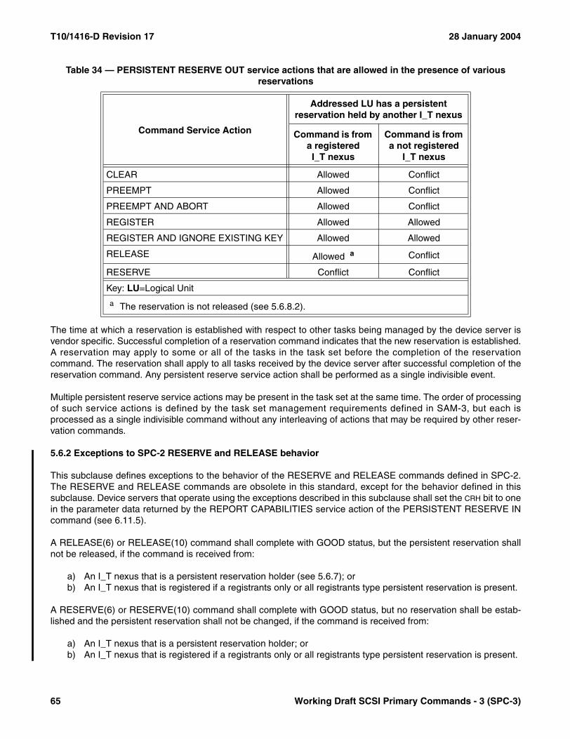
T10/1416-D Revision 17 28 January 2004
The time at which a reservation is established with respect to other tasks being managed by the device server isvendor specific. Successful completion of a reservation command indicates that the new reservation is established.A reservation may apply to some or all of the tasks in the task set before the completion of the reservationcommand. The reservation shall apply to all tasks received by the device server after successful completion of thereservation command. Any persistent reserve service action shall be performed as a single indivisible event.
Multiple persistent reserve service actions may be present in the task set at the same time. The order of processingof such service actions is defined by the task set management requirements defined in SAM-3, but each isprocessed as a single indivisible command without any interleaving of actions that may be required by other reser-vation commands.
5.6.2 Exceptions to SPC-2 RESERVE and RELEASE behavior
This subclause defines exceptions to the behavior of the RESERVE and RELEASE commands defined in SPC-2.The RESERVE and RELEASE commands are obsolete in this standard, except for the behavior defined in thissubclause. Device servers that operate using the exceptions described in this subclause shall set the CRH bit to onein the parameter data returned by the REPORT CAPABILITIES service action of the PERSISTENT RESERVE INcommand (see 6.11.5).
A RELEASE(6) or RELEASE(10) command shall complete with GOOD status, but the persistent reservation shallnot be released, if the command is received from:
a) An I_T nexus that is a persistent reservation holder (see 5.6.7); orb) An I_T nexus that is registered if a registrants only or all registrants type persistent reservation is present.
A RESERVE(6) or RESERVE(10) command shall complete with GOOD status, but no reservation shall be estab-lished and the persistent reservation shall not be changed, if the command is received from:
a) An I_T nexus that is a persistent reservation holder; orb) An I_T nexus that is registered if a registrants only or all registrants type persistent reservation is present.
Table 34 — PERSISTENT RESERVE OUT service actions that are allowed in the presence of various reservations
Command Service Action
Addressed LU has a persistent reservation held by another I_T nexus
Command is from a registeredI_T nexus
Command is from a not registered
I_T nexus
CLEAR Allowed Conflict
PREEMPT Allowed Conflict
PREEMPT AND ABORT Allowed Conflict
REGISTER Allowed Allowed
REGISTER AND IGNORE EXISTING KEY Allowed Allowed
RELEASE Allowed a Conflict
RESERVE Conflict Conflict
Key: LU=Logical Unit
a The reservation is not released (see 5.6.8.2).
65 Working Draft SCSI Primary Commands - 3 (SPC-3)
28 January 2004 T10/1416-D Revision 17
In all other cases, a RESERVE(6) command, RESERVE(10) command, RELEASE(6) command, or RELEASE(10)command shall be processed as defined in SPC-2.
5.6.3 Preserving persistent reservations and registrations
The application client may request activation of the persist through power loss device server capability to preservethe persistent reservation and registrations across power cycles by setting the APTPL bit to one in the PERSISTENTRESERVE OUT parameter data sent with a REGISTER service action or REGISTER AND IGNORE EXISTINGKEY service action.
After the application client enables the persist through power loss capability the device server shall preserve thepersistent reservation, if any, and all current and future registrations associated with the logical unit to which theREGISTER service action or the REGISTER AND IGNORE EXISTING KEY service action was addressed until anapplication client disables the persist through power loss capability. The APTPL value from the most recent success-fully completed REGISTER or REGISTER AND IGNORE EXISTING KEY service action from any application clientshall determine the logical unit’s behavior in the event of a power loss.
The device server shall preserve the following information for each existing registration across any hard reset,logical unit reset, or I_T nexus loss, and if the persist through power loss capability is enabled, across any powercycle:
a) For SCSI transport protocols where initiator port names (see 3.1.46) are required, the initiator port name;otherwise, the initiator port identifier (see 3.1.45);
b) Reservation key; andc) Indication of the target port to which the registration was applied.
The device server shall preserve the following information about the existing persistent reservation across any hardreset, logical unit reset, or I_T nexus loss, and if the persist through power loss capability is enabled, across anypower cycle:
a) For SCSI transport protocols where initiator port names are required, the initiator port name; otherwise, theinitiator port identifier;
b) Reservation key;c) Scope;d) Type; ande) Indication of the target port through which the reservation was established.
NOTE 9 - The scope of a persistent reservation is always LU_SCOPE. For an all registrants type persistent reser-vation, only the scope and type need to be preserved.
The capability of preserving persistent reservations and registrations across power cycles requires the use of anonvolatile memory within the SCSI device. Any SCSI device and logical unit that supports the persist throughpower loss capability of persistent reservation and has nonvolatile memory that is not ready shall allow thefollowing commands into the task set:
a) INQUIRY;b) LOG SENSE;c) READ BUFFER;d) REPORT LUNS;e) REQUEST SENSE;f) START STOP UNIT (with the START bit set to one and POWER CONDITIONS field value of 0h); andg) WRITE BUFFER.
Working Draft SCSI Primary Commands - 3 (SPC-3) 66
T10/1416-D Revision 17 28 January 2004
When nonvolatile memory has not become ready since a power cycle, commands other than those listed in thissubclause shall return CHECK CONDITION status. The sense key shall be set to NOT READY and the additionalsense code shall be set as described in table 165 (see 6.29).
5.6.4 Finding persistent reservations and reservation keys
5.6.4.1 Summary of commands for finding persistent reservations and reservation keys
The application client may obtain information about the persistent reservation and the reservation keys (i.e., regis-trations) that are present within a device server by issuing a PERSISTENT RESERVE IN command with a READRESERVATION service action or a READ KEYS service action.
5.6.4.2 Reporting reservation keys
An application client may issue a PERSISTENT RESERVE IN command with READ KEYS service action todetermine if any I_T nexuses have been registered with a logical unit through any target port.
In response to a PERSISTENT RESERVE IN with READ KEYS service action the device server shall report thefollowing:
a) The current PRgeneration value (see 6.11.3); andb) The reservation key for every I_T nexus that is currently registered regardless of the target port through
which the registration occurred.
The PRgeneration value allows the application client to verify that the configuration of the I_T nexuses registeredwith a logical unit has not been modified.
The application client may examine the reservation keys to identify relationships between I_T nexuses based onmechanisms that are outside the scope of this standard. Duplicate reservation keys shall be reported if multiple I_Tnexuses are registered using the same reservation key.
5.6.4.3 Reporting the persistent reservation
An application client may issue a PERSISTENT RESERVE IN command with READ RESERVATION service actionto receive the persistent reservation information.
In response to a PERSISTENT RESERVE IN command with READ RESERVATION service action the deviceserver shall report the following as an uninterrupted series of actions:
a) The current PRgeneration value (see 6.11.3);b) The registered reservation key, if any, associated with the I_T nexus that holds the persistent reservation;
andc) The scope and type of the persistent reservation, if any.
If an application client uses a different reservation key for each I_T_L nexus the application client may use thereservation key to associate the persistent reservation with the initiator port that holds the persistent reservation.This association is done using techniques that are outside the scope of this standard.
5.6.5 Registering
To establish a persistent reservation the application client shall first register an I_T nexus with a logical unit. Anapplication client registers with a logical unit by issuing a PERSISTENT RESERVE OUT command withREGISTER service action or REGISTER AND IGNORE EXISTING KEY service action.
67 Working Draft SCSI Primary Commands - 3 (SPC-3)
28 January 2004 T10/1416-D Revision 17
If the I_T nexus has not yet established a reservation key or the reservation key and registration have beenremoved, the registration is accomplished by issuing a PERSISTENT RESERVE OUT command with REGISTERservice action with the following parameters:
a) APTPL bit optionally set to one;b) RESERVATION KEY field set to zero; andc) SERVICE ACTION RESERVATION KEY field set to a non-zero value.
If the I_T nexus has an established registration it may change its reservation key. This is accomplished by issuing aPERSISTENT RESERVE OUT command with REGISTER service action with the following parameters:
a) APTPL bit optionally set to one;b) RESERVATION KEY field set to the value of the reservation key that is registered for the I_T_L nexus; andc) SERVICE ACTION RESERVATION KEY field set to a non-zero value.
If the SERVICE ACTION RESERVATION KEY field is set to zero, the registration shall be removed (see 5.6.8.1.1).
Alternatively, an application client may establish a reservation key for an I_T nexus without regard for whether onehas previously been established by issuing a PERSISTENT RESERVE OUT command with REGISTER ANDIGNORE EXISTING KEY service action and the following parameters:
a) APTPL bit optionally set to one; andb) SERVICE ACTION RESERVATION KEY field set to a non-zero value.
If the SERVICE ACTION RESERVATION KEY field is set to zero and the I_T_L nexus is registered, the registration shallbe removed (see 5.6.8.1.1).
If a PERSISTENT RESERVE OUT command with REGISTER AND IGNORE EXISTING KEY service action issent when an established registration exists, that registration shall be superseded with the specified service actionreservation key. If a PERSISTENT RESERVE OUT command with REGISTER AND IGNORE EXISTING KEYservice action is sent when there is no established registration, a new registration shall be established.
If a PERSISTENT RESERVE OUT command with a REGISTER service action or a REGISTER AND IGNOREEXISTING KEY service action is attempted, but there are insufficient device server resources to complete theoperation, the device server shall return a CHECK CONDITION status. The sense key shall be set to ILLEGALREQUEST and the additional sense code shall be set to INSUFFICIENT REGISTRATION RESOURCES.
In response to a PERSISTENT RESERVE OUT command with a REGISTER service action or a REGISTER ANDIGNORE EXISTING KEY service action the device server shall perform a registration by doing the following as anuninterrupted series of actions:
a) Process the registration request regardless of any persistent reservations;b) Process the APTPL bit;c) Ignore the contents of the SCOPE and TYPE fields;d) Map the reservation key to the registering I_T nexus using the indication of the target port associated with
the registration and either the initiator port name (see 3.1.46) on SCSI transport protocols where portnames are required or the initiator port identifier (see 3.1.45) on SCSI transport protocols where portnames are not required;
e) Register the reservation key without changing any persistent reservation that may exist; andf) Retain the reservation key and associated information.
After the registration request has been processed, the device server shall then allow other PERSISTENTRESERVE OUT commands from the registered I_T nexus to be processed. For each I_T nexus that is the source aPERSISTENT RESERVE OUT command with a REGISTER service action or a REGISTER AND IGNORE
Working Draft SCSI Primary Commands - 3 (SPC-3) 68

T10/1416-D Revision 17 28 January 2004
EXISTING KEY service action, the device server shall retain the reservation key until the key is changed by a newPERSISTENT RESERVE OUT command with the REGISTER service action or the REGISTER AND IGNOREEXISTING KEY service action from the same I_T nexus or until the registration is removed (see 5.6.8).
Any PERSISTENT RESERVE OUT command service action received from an unregistered I_T nexus, other thanthe REGISTER or the REGISTER AND IGNORE EXISTING KEY service action, shall be rejected with a RESER-VATION CONFLICT status.
It is not an error for an I_T nexus that is registered to be registered again with the same reservation key or a newreservation key. A registration shall have no effect on any other registrations (e.g., when more than one I_T nexusis registered with the same reservation key and one of those I_T nexuses registers again it has no effect on theother I_T nexus’ registrations). A registration that contains a non-zero value in the SERVICE ACTION RESERVATION
KEY field shall have no effect on any persistent reservations (i.e., the reservation key for an I_T nexus may bechanged without affecting any previously created persistent reservation).
Multiple I_T nexuses may be registered with the same reservation key. An application client may use the samereservation key for other I_T nexuses and logical units.
5.6.6 Reserving
An application client creates a persistent reservation by issuing a PERSISTENT RESERVE OUT command withRESERVE service action through a registered I_T nexus with the following parameters:
a) RESERVATION KEY set to the value of the reservation key that is registered for the I_T_L nexus; andb) TYPE and SCOPE fields set to the persistent reservation being created.
Only one persistent reservation is allowed at a time per logical unit and that persistent reservation has a scope ofLU_SCOPE.
If the device server receives a PERSISTENT RESERVE OUT command from an I_T nexus other than a persistentreservation holder (see 5.6.7) that attempts to create a persistent reservation when a persistent reservationalready exists for the logical unit, then the command shall be rejected with a RESERVATION CONFLICT status.
If a persistent reservation holder attempts to modify the TYPE or SCOPE of an existing persistent reservation, thenthe command shall be rejected with a RESERVATION CONFLICT status.
If the device server receives a PERSISTENT RESERVE OUT command with RESERVE service action where theTYPE and SCOPE are the same as the existing TYPE and SCOPE from a persistent reservation holder, it shall not makeany change to the existing persistent reservation and shall return a GOOD status.
See 5.6.1 for information on when a persistent reservation takes effect.
5.6.7 Persistent reservation holder
The persistent reservation holder is determined by the type of the persistent reservation as follows:
a) For a persistent reservation of the type Write Exclusive – All Registrants or Exclusive Access – All Regis-trants, the persistent reservation holder is any registered I_T nexus; or
b) For all other persistent reservation types, the persistent reservation holder is the I_T nexus from which thePERSISTENT RESERVE OUT command with RESERVE service action, PREEMPT service action, orPREEMPT AND ABORT service action was received.
69 Working Draft SCSI Primary Commands - 3 (SPC-3)
28 January 2004 T10/1416-D Revision 17
A persistent reservation holder has its reservation key returned in the parameter data from a PERSISTENTRESERVE IN command with READ RESERVATION service action as follows:
a) For a persistent reservation of the type Write Exclusive – All Registrants or Exclusive Access – All Regis-trants, the reservation key shall be set to zero; or
b) For all other persistent reservation types, the reservation key shall be set to the registered reservation keyfor the I_T nexus that holds the persistent reservation.
It is not an error for a persistent reservation holder to send a PERSISTENT RESERVE OUT command withRESERVE service action to the reserved logical unit with TYPE and SCOPE fields that match those of the persistentreservation (see 5.6.6).
A persistent reservation holder is allowed to release the persistent reservation using the PERSISTENT RESERVEOUT command with RELEASE service action.
If the registration of the persistent reservation holder is removed (see 5.6.8.1.1), the reservation is automaticallyreleased. When the persistent reservation holder is more than one I_T nexus, the reservation is not automaticallyreleased until the registrations for all persistent reservation holder I_T nexuses are removed.
5.6.8 Releasing persistent reservations and removing registrations
5.6.8.1 Overview
5.6.8.1.1 Summary of service actions that release persistent reservations and remove registrations
An application client may release or preempt the persistent reservation by issuing one of the following commandsthrough a registered I_T nexus with the RESERVATION KEY field set to the reservation key value that is registered forthe I_T_L nexus:
a) A PERSISTENT RESERVE OUT command with RELEASE service action from a persistent reservationholder (see 5.6.8.2);
b) A PERSISTENT RESERVE OUT command with PREEMPT service action specifying the reservation keyof the persistent reservation holder or holders (see 5.6.8.4);
c) A PERSISTENT RESERVE OUT command with PREEMPT AND ABORT service action specifying thereservation key of the persistent reservation holder or holders (see 5.6.8.5);
d) A PERSISTENT RESERVE OUT command with CLEAR service action (see 5.6.8.6); ore) If the I_T nexus is the persistent reservation holder and the persistent reservation is not an all registrants
type, a PERSISTENT RESERVE OUT command with REGISTER service action or REGISTER ANDIGNORE EXISTING KEY service action with the SERVICE ACTION RESERVATION KEY field set to zero (see5.6.8.3).
An application client may remove registrations by issuing one of the following commands through a registered I_Tnexus with the RESERVATION KEY field set to the reservation key value that is registered for the I_T_L nexus:
a) A PERSISTENT RESERVE OUT command with PREEMPT service action with the SERVICE ACTION RESER-VATION KEY field set to the reservation key (see 5.6.8.4) to be removed;
b) A PERSISTENT RESERVE OUT command with PREEMPT AND ABORT service action with the SERVICE
ACTION RESERVATION KEY field set to the reservation key (see 5.6.8.5) to be removed;c) A PERSISTENT RESERVE OUT command with CLEAR service action (see 5.6.8.6); ord) A PERSISTENT RESERVE OUT command with REGISTER service action or REGISTER AND IGNORE
EXISTING KEY service action with the SERVICE ACTION RESERVATION KEY field set to zero (see 5.6.8.3).
Working Draft SCSI Primary Commands - 3 (SPC-3) 70
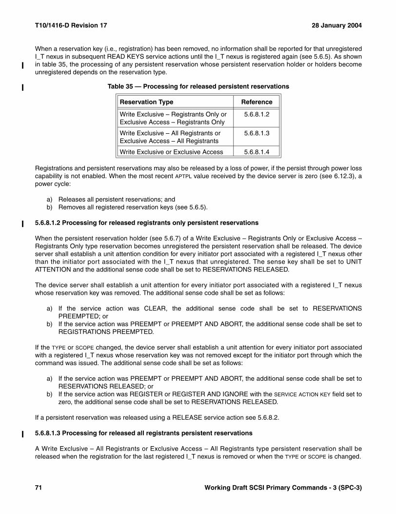
T10/1416-D Revision 17 28 January 2004
When a reservation key (i.e., registration) has been removed, no information shall be reported for that unregisteredI_T nexus in subsequent READ KEYS service actions until the I_T nexus is registered again (see 5.6.5). As shownin table 35, the processing of any persistent reservation whose persistent reservation holder or holders becomeunregistered depends on the reservation type.
Registrations and persistent reservations may also be released by a loss of power, if the persist through power losscapability is not enabled. When the most recent APTPL value received by the device server is zero (see 6.12.3), apower cycle:
a) Releases all persistent reservations; andb) Removes all registered reservation keys (see 5.6.5).
5.6.8.1.2 Processing for released registrants only persistent reservations
When the persistent reservation holder (see 5.6.7) of a Write Exclusive – Registrants Only or Exclusive Access –Registrants Only type reservation becomes unregistered the persistent reservation shall be released. The deviceserver shall establish a unit attention condition for every initiator port associated with a registered I_T nexus otherthan the initiator port associated with the I_T nexus that unregistered. The sense key shall be set to UNITATTENTION and the additional sense code shall be set to RESERVATIONS RELEASED.
The device server shall establish a unit attention for every initiator port associated with a registered I_T nexuswhose reservation key was removed. The additional sense code shall be set as follows:
a) If the service action was CLEAR, the additional sense code shall be set to RESERVATIONSPREEMPTED; or
b) If the service action was PREEMPT or PREEMPT AND ABORT, the additional sense code shall be set toREGISTRATIONS PREEMPTED.
If the TYPE or SCOPE changed, the device server shall establish a unit attention for every initiator port associatedwith a registered I_T nexus whose reservation key was not removed except for the initiator port through which thecommand was issued. The additional sense code shall be set as follows:
a) If the service action was PREEMPT or PREEMPT AND ABORT, the additional sense code shall be set toRESERVATIONS RELEASED; or
b) If the service action was REGISTER or REGISTER AND IGNORE with the SERVICE ACTION KEY field set tozero, the additional sense code shall be set to RESERVATIONS RELEASED.
If a persistent reservation was released using a RELEASE service action see 5.6.8.2.
5.6.8.1.3 Processing for released all registrants persistent reservations
A Write Exclusive – All Registrants or Exclusive Access – All Registrants type persistent reservation shall bereleased when the registration for the last registered I_T nexus is removed or when the TYPE or SCOPE is changed.
Table 35 — Processing for released persistent reservations
Reservation Type Reference
Write Exclusive – Registrants Only orExclusive Access – Registrants Only
5.6.8.1.2
Write Exclusive – All Registrants orExclusive Access – All Registrants
5.6.8.1.3
Write Exclusive or Exclusive Access 5.6.8.1.4
71 Working Draft SCSI Primary Commands - 3 (SPC-3)

28 January 2004 T10/1416-D Revision 17
The device server shall establish a unit attention for every initiator port associated with a registered I_T nexuswhose reservation key was removed. The additional sense code shall be set as follows:
a) If the service action was CLEAR, the additional sense code shall be set to RESERVATIONSPREEMPTED; or
b) If the service action was PREEMPT or PREEMPT AND ABORT, the additional sense code shall be set toREGISTRATIONS PREEMPTED.
If a persistent reservation was released using a RELEASE service action see 5.6.8.2.
5.6.8.1.4 Processing for other released persistent reservations
When the persistent reservation holder (see 5.6.7) of a Write Exclusive or Exclusive Access type reservationbecomes unregistered the persistent reservation shall be released.
5.6.8.2 Releasing
Only the persistent reservation holder (see 5.6.7) is allowed to release a persistent reservation.
An application client releases the persistent reservation by issuing a PERSISTENT RESERVE OUT command withRELEASE service action through an I_T nexus that is a persistent reservation holder with the following parameters:
a) RESERVATION KEY field set to the value of the reservation key that is registered for the I_T_L nexus; andb) TYPE and SCOPE fields set to match the persistent reservation being released.
In response to a persistent reservation release request from the persistent reservation holder the device servershall perform a release by doing the following as an uninterrupted series of actions:
a) Release the persistent reservation;b) Not remove any registration(s);c) If the released persistent reservation is a registrants only or all registrants type persistent reservation, the
device server shall establish a unit attention condition for every initiator port associated with a registeredI_T nexus other than the initiator port that issued the PERSISTENT RESERVE OUT command withRELEASE service action. The sense key shall be set to UNIT ATTENTION and the additional sense codeshall be set to RESERVATIONS RELEASED; and
d) If the persistent reservation is of any other type the device server shall not establish a unit attentioncondition.
The established persistent reservation shall not be altered and the device server shall return a CHECKCONDITION status for a PERSISTENT RESERVE OUT command that specifies the release of a persistent reser-vation if:
a) The requesting I_T nexus is a persistent reservation holder (see 5.6.7); andb) The SCOPE and TYPE fields do not match the scope and type of the established persistent reservation.
The sense key shall be set to ILLEGAL REQUEST and additional sense code shall be set to INVALID RELEASEOF PERSISTENT RESERVATION.
If there is no persistent reservation or in response to a persistent reservation release request from a registered I_Tnexus that is not a persistent reservation holder (see 5.6.7), the device server shall do the following:
a) Not release the persistent reservation (if any); andb) Not remove any registrations.
Working Draft SCSI Primary Commands - 3 (SPC-3) 72
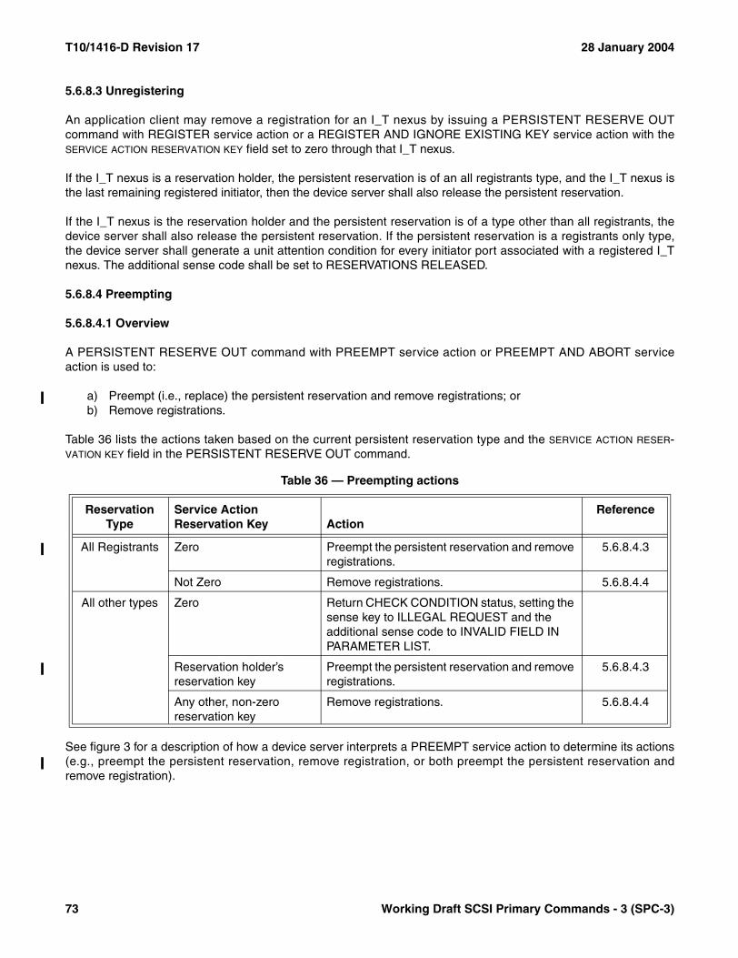
T10/1416-D Revision 17 28 January 2004
5.6.8.3 Unregistering
An application client may remove a registration for an I_T nexus by issuing a PERSISTENT RESERVE OUTcommand with REGISTER service action or a REGISTER AND IGNORE EXISTING KEY service action with theSERVICE ACTION RESERVATION KEY field set to zero through that I_T nexus.
If the I_T nexus is a reservation holder, the persistent reservation is of an all registrants type, and the I_T nexus isthe last remaining registered initiator, then the device server shall also release the persistent reservation.
If the I_T nexus is the reservation holder and the persistent reservation is of a type other than all registrants, thedevice server shall also release the persistent reservation. If the persistent reservation is a registrants only type,the device server shall generate a unit attention condition for every initiator port associated with a registered I_Tnexus. The additional sense code shall be set to RESERVATIONS RELEASED.
5.6.8.4 Preempting
5.6.8.4.1 Overview
A PERSISTENT RESERVE OUT command with PREEMPT service action or PREEMPT AND ABORT serviceaction is used to:
a) Preempt (i.e., replace) the persistent reservation and remove registrations; orb) Remove registrations.
Table 36 lists the actions taken based on the current persistent reservation type and the SERVICE ACTION RESER-VATION KEY field in the PERSISTENT RESERVE OUT command.
See figure 3 for a description of how a device server interprets a PREEMPT service action to determine its actions(e.g., preempt the persistent reservation, remove registration, or both preempt the persistent reservation andremove registration).
Table 36 — Preempting actions
ReservationType
Service Action Reservation Key Action
Reference
All Registrants Zero Preempt the persistent reservation and remove registrations.
5.6.8.4.3
Not Zero Remove registrations. 5.6.8.4.4
All other types Zero Return CHECK CONDITION status, setting the sense key to ILLEGAL REQUEST and the additional sense code to INVALID FIELD IN PARAMETER LIST.
Reservation holder’s reservation key
Preempt the persistent reservation and remove registrations.
5.6.8.4.3
Any other, non-zero reservation key
Remove registrations. 5.6.8.4.4
73 Working Draft SCSI Primary Commands - 3 (SPC-3)

28 January 2004 T10/1416-D Revision 17
Figure 3 — Device server interpretation of PREEMPT service action
Requesting initiator
registered?
Existingpersistent
reservation?
PREEMPT service action
a) Remove registration pointed to bythe SERVICE ACTION RESERVATION KEY
b) Release persistent reservationc) Create persistent reservation using new TYPE and SCOPE
Remove registrationpointed to by the SERVICE
ACTION RESERVATION KEY
RESERVATION CONFLICT
status
Done
SERVICE ACTIONRESERVATION KEY
matches reservation keyof the persistent reser-
vation holder?
Done
Done
No
No
Valid RESERVATION
KEY & SERVICE ACTION RESERVATION
KEY?
AllRegistrantspersistent
reservation?
Yes
Yes
No
No
Yes
No
SERVICE ACTIONRESERVATION KEY
is zero?
a) Remove all other registrationsb) Release persistent reservationc) Create persistent reservation using new TYPE and SCOPE
No
Yes
Yes
No
Yes
SERVICE ACTIONRESERVATION KEY
is zero?
ILLEGALREQUESTsense key
Yes
Done
Remove registrationpointed to by the SERVICE
ACTION RESERVATION KEY
Working Draft SCSI Primary Commands - 3 (SPC-3) 74
T10/1416-D Revision 17 28 January 2004
5.6.8.4.2 Failed persistent reservation preempt
If the preempting I_T nexus’ PREEMPT service action or PREEMPT AND ABORT service action fails (e.g.,repeated TASK SET FULL status, repeated BUSY status, SCSI protocol time-out, or time-out due to the task setbeing blocked due to failed initiator port or failed SCSI initiator device), the application client may send a LOGICALUNIT RESET task management function to the failing logical unit to remove blocking tasks and then reissue thepreempting service action.
5.6.8.4.3 Preempting persistent reservations and registration handling
An application client may preempt the persistent reservation with another persistent reservation by issuing aPERSISTENT RESERVE OUT command with PREEMPT service action or PREEMPT AND ABORT service actionthrough a registered I_T nexus with the following parameters:
a) RESERVATION KEY field set to the value of the reservation key that is registered for the I_T_L nexus;b) SERVICE ACTION RESERVATION KEY field set to the value of the reservation key of the persistent reservation
to be preempted; andc) TYPE and SCOPE fields set to define a new persistent reservation. The SCOPE and TYPE of the persistent
reservation created by the preempting I_T nexus may be different than those of the persistent reservationbeing preempted.
If the SERVICE ACTION RESERVATION KEY field identifies a persistent reservation holder (see 5.6.7), the device servershall perform a preempt by doing the following as an uninterrupted series of actions:
a) Release the persistent reservation for the holder identified by the SERVICE ACTION RESERVATION KEY field;b) Remove the registrations for all I_T nexuses identified by the SERVICE ACTION RESERVATION KEY field,
except the I_T nexus that is being used for the PERSISTENT RESERVE OUT command. If an all regis-trants persistent reservation is present and the SERVICE ACTION RESERVATION KEY field is set to zero then allregistrations shall be removed except for the I_T nexus that is being used for the PERSISTENT RESERVEOUT command;
c) Establish a persistent reservation for the preempting I_T nexus using the contents of the SCOPE and TYPE
fields;d) Process tasks as defined in 5.6.1; ande) Establish a unit attention condition for every initiator port associated with every I_T nexus that lost its
persistent reservation and/or registration. The sense key shall be set to UNIT ATTENTION and theadditional sense code shall be set to REGISTRATIONS PREEMPTED.
After GOOD status has been returned for the PERSISTENT RESERVE OUT command, new tasks are subject tothe persistent reservation restrictions established by the preempting I_T nexus.
The following tasks shall be subjected in a vendor specific manner either to the restrictions established by thepersistent reservation being preempted or to the restrictions established by the preempting I_T nexus:
a) A task received after the arrival, but before the completion of the PERSISTENT RESERVE OUT commandwith the PREEMPT service action or the PREEMPT AND ABORT service action; or
b) A task in the dormant, blocked, or enable state at the time the PERSISTENT RESERVE OUT commandwith the PREEMPT service action or the PREEMPT AND ABORT service action is received.
Completion status shall be returned for each task.
A PERSISTENT RESERVE OUT with a PREEMPT service action or a PREEMPT AND ABORT service action withthe SERVICE ACTION RESERVATION KEY value equal to the persistent reservation holder’s reservation key is not anerror. In that case the device server shall establish the new persistent reservation and maintain the registration.
75 Working Draft SCSI Primary Commands - 3 (SPC-3)
28 January 2004 T10/1416-D Revision 17
5.6.8.4.4 Removing registrations
When a registered reservation key does not identify a persistent reservation holder (see 5.6.7), an applicationclient may remove the registration(s) without affecting any persistent reservations by issuing a PERSISTENTRESERVE OUT command with PREEMPT service action through a registered I_T nexus with the following param-eters:
a) RESERVATION KEY field set to the value of the reservation key that is registered for the I_T nexus; andb) SERVICE ACTION RESERVATION KEY field set to match the reservation key of the registration or registrations
being removed.
If the SERVICE ACTION RESERVATION KEY field does not identify the persistent reservation holder or there is nopersistent reservation holder (i.e., there is no persistent reservation), the device server shall perform a preempt bydoing the following in an uninterrupted series of actions:
a) Remove the registrations for all I_T nexuses specified by the SERVICE ACTION RESERVATION KEY field;b) Ignore the contents of the SCOPE and TYPE fields;c) Process tasks as defined in 5.6.1; andd) Establish a unit attention condition for every initiator port associated with every I_T nexus that lost its regis-
tration other than the initiator port that sent the PERSISTENT RESERVE OUT command. The sense keyshall be set to UNIT ATTENTION and the additional sense code shall be set to REGISTRATIONSPREEMPTED.
If a PERSISTENT RESERVE OUT with a PREEMPT service action or a PREEMPT AND ABORT service actionsets the SERVICE ACTION RESERVATION KEY field to a value that does not match any registered reservation key thedevice server shall return a RESERVATION CONFLICT status.
It is not an error for a PERSISTENT RESERVE OUT with a PREEMPT service action or a PREEMPT AND ABORTservice action to set the RESERVATION KEY and the SERVICE ACTION RESERVATION KEY to the same value, however,no unit attention condition is established for the initiator port that sent the PERSISTENT RESERVE OUTcommand.
5.6.8.5 Preempting and aborting
The application client’s request for and the device server’s responses to a PERSISTENT RESERVE OUTcommand PREEMPT AND ABORT service action are identical to the responses to a PREEMPT service action(see 5.6.8.4) except for the following additions. If no reservation conflict occurred, the device server shall performthe following uninterrupted series of actions:
a) If the persistent reservation is not an all registrants type then:A) If the TST field is 000b (see 7.4.6) and an ACA condition exists for initiator ports other than the initiator
port associated with the persistent reservation being preempted, the PERSISTENT RESERVE OUTcommand shall be terminated prior to processing with a status of ACA ACTIVE if the NACA bit equalsone in the CDB CONTROL byte (see SAM-2) or BUSY if the NACA equals zero; or
B) If the TST field contains 001b, then the ACA condition for initiator ports other than the initiator portassociated with the persistent reservation being preempted shall not prevent the processing of thePERSISTENT RESERVE OUT command;
b) Perform the uninterrupted series of actions described for the PREEMPT service action (see 5.6.8.4);c) All tasks from the initiator port or initiator ports associated with the persistent reservations being
preempted (called preempted tasks) except the task containing the PERSISTENT RESERVE OUTcommand itself shall be terminated. Application client notification shall be provided, as specified by the TAS
Working Draft SCSI Primary Commands - 3 (SPC-3) 76
T10/1416-D Revision 17 28 January 2004
bit in the Control mode page (see 7.4.6) that applies to the initiator port associated with the persistentreservation being preempted (called the preempted initiator port), as follows:A) If the TAS bit is set to zero then all preempted tasks shall be terminated as if an ABORT TASK SET task
management function had been performed by each preempted initiator port; orB) If the TAS bit is set to one then all preempted tasks from initiator ports other than the initiator port that
sent the PREEMPT AND ABORT service action shall be terminated with a TASK ABORTED status(see SAM-2). Any preempted tasks from the initiator port that sent the PREEMPT AND ABORTservice action shall be terminated as if an ABORT TASK SET task management function had beenperformed by that initiator port.
If a terminated task is a command that causes the device server to generate additional commands anddata transfers (e.g., EXTENDED COPY), all commands and data transfers generated by the commandshall be terminated before the ABORT TASK SET task management function is considered completed.After the ABORT TASK SET function has completed, all new tasks are subject to the persistent reservationrestrictions established by the preempting initiator port;
d) If the persistent reservation is not an all registrants type then the device server shall clear any ACAcondition associated with an initiator port being preempted and shall clear any tasks with an ACA attributefrom that initiator port;
e) If the persistent reservation is an all registrants type then the device server shall clear any ACA conditionand shall clear any tasks with an ACA attribute; and
f) For logical units that implement the PREVENT ALLOW MEDIUM REMOVAL command, the device servershall perform an action equivalent to the processing of a PREVENT ALLOW MEDIUM REMOVALcommand with the PREVENT field equal to zero for the initiator port or initiator ports associated with thepersistent reservation being preempted (see 6.13).
The actions described in this subclause shall be performed for all I_T nexuses that are registered with the SERVICE
ACTION RESERVATION KEY value, without regard for whether the preempted I_T nexuses hold the persistent reser-vation. If an all registrants persistent reservation is present the device server shall abort all tasks for all registeredI_T nexuses.
5.6.8.6 Clearing
Any application client may release the persistent reservation and remove all registrations from a device server byissuing a PERSISTENT RESERVE OUT command with CLEAR service action through a registered I_T nexus withthe following parameter:
a) RESERVATION KEY field set to the value of the reservation key that is registered for the I_T_L nexus.
In response to this request the device server shall perform a clear by doing the following as part of an uninterruptedseries of actions:
a) Release the persistent reservation, if any;b) Remove all registration(s) (see 5.6.5);c) Ignore the contents of the SCOPE and TYPE fields;d) Continue normal execution of any tasks from any I_T nexus that have been accepted by the device server
as allowed (i.e., nonconflicting); ande) Establish a unit attention condition for every initiator port associated with every registered I_T nexus other
than the initiator port that sent the PERSISTENT RESERVE OUT command with CLEAR service action.The sense key shall be set to UNIT ATTENTION and the additional sense code shall be set to RESERVA-TIONS PREEMPTED.
Application clients should not use the CLEAR service action except during recoveries that are associated withinitiator port or system reconfiguration, since the effect of the CLEAR service action is to remove the persistentreservation management conventions that protect data integrity.
77 Working Draft SCSI Primary Commands - 3 (SPC-3)

28 January 2004 T10/1416-D Revision 17
5.7 Multiple target port and initiator port behavior
SAM-2 specifies the behavior of logical units being accessed by application clients through more than one initiatorport through one or more target ports. Additional initiator ports and target ports provide alternate paths throughwhich the device server may be reached. An alternate path may be used to improve the availability of logical unitsin the presence of certain types of failures and to improve the performance between an application client andlogical unit when some paths may be busy.
If a SCSI target device has more than one target port, the arbitration and connection management among thetarget ports is vendor specific. If one target port is being used by an initiator port, accesses attempted throughother target port(s) may:
a) Receive a status of BUSY; orb) Be accepted as if the other target port(s) were not in use.
The device server shall indicate the presence of multiple target ports by setting the MULTIP bit to one in its standardINQUIRY data.
Only the following operations allow an initiator port to interact with the tasks of other initiator ports, regardless of thetarget port:
a) The PERSISTENT RESERVE OUT with PREEMPT service action preempts persistent reservations (see5.6.8.4);
b) The PERSISTENT RESERVE OUT with PREEMPT AND ABORT service action preempts persistentreservations and aborts tasks (see 5.6.8.5);
c) The PERSISTENT RESERVE OUT with CLEAR service action releases persistent reservations for allinitiator ports (see 5.6.8.6);
d) The LOGICAL UNIT RESET task management function removes all tasks for all initiator ports for theaddressed logical unit and any logical units issuing from it in a hierarchical addressing structure (seeSAM-2). Persistent reservations remain unmodified; and
e) The CLEAR TASK SET task management function removes all tasks for all initiator ports for the selectedlogical unit. Most other logical unit states remain unmodified, including MODE SELECT parameters, reser-vations, and ACA (see SAM-2).
5.8 Asymmetric logical unit access
5.8.1 Introduction to asymmetric logical unit access
Logical units may be connected to the service delivery subsystem via multiple target ports (see SAM-2).Asymmetric logical unit access occurs when the access characteristics of one port may differ from those of anotherport. SCSI target devices with target ports implemented in separate physical units may need to designate differinglevels of access for the target ports associated with each logical unit. While commands and task managementfunctions (see SAM-2) may be routed to a logical unit through any target port, the performance may not be optimal,and the allowable command set may be less complete than when the same commands and task managementfunctions and are routed through a different target port. When a failure on the path to one target port is detected,the SCSI target device may perform automatic internal reconfiguration to make a logical unit accessible from adifferent set of target ports or may be instructed by the initiator to make a logical unit accessible from a different setof target ports.
A target port characteristic called target port asymmetric access state (see 5.8.4) defines properties of a target portand the allowable command set for a logical unit when commands and task management functions are routedthrough the target port maintaining that state.
Working Draft SCSI Primary Commands - 3 (SPC-3) 78

T10/1416-D Revision 17 28 January 2004
A target port group is defined as a set of target ports that are in the same target port asymmetric access state at alltimes. A target port group asymmetric access state is defined as the target port asymmetric access state commonto the set of target ports in a target port group. The grouping of target ports is vendor specific.
A logical unit may have commands and task management functions routed through multiple target port groups.Logical units support asymmetric logical unit access if different target port groups may be in different target portgroup asymmetric access states.
An example of asymmetric logical unit access is a SCSI controller device with two separated controllers where alltarget ports on one controller are in the same asymmetric access state with respect to a logical unit and aremembers of the same target port group. Target ports on the other controller are members of another target portgroup. The behavior of each target port group may be different with respect to a logical unit, but all members of asingle target port group are always in the same target port asymmetric access state with respect to a logical unit.
An example of target port groups is shown in figure 4.
5.8.2 Explicit and implicit asymmetric logical unit access
Asymmetric logical unit access may be managed explicitly by an application client using the REPORT TARGETPORT GROUPS (see 6.24) and SET TARGET PORT GROUPS (see 6.28) commands.
Alternatively, asymmetric logical unit access may be managed implicitly by the SCSI target device based on thetype of transactions being routed through each target port and the internal configuration capabilities of the targetport group(s) through which the logical unit may be accessed. The logical units may attempt to maintain full perfor-mance across the target port groups that are busiest and that show the most reliable performance, allowing othertarget port groups to select a lower performance target port asymmetric access state.
If both explicit and implicit asymmetric logical unit access are implemented the precedence of one over the other isvendor specific.
5.8.3 Discovery of asymmetric logical unit access behavior
SCSI logical units with asymmetric logical unit access may be identified using the INQUIRY command. The value inthe asymmetric logical units access (ALUA) field (see 6.4.2) indicates whether or not the logical unit supportsasymmetric logical unit access and if so whether implicit or explicit management is supported. The asymmetricaccess states supported by a logical unit may be determined by the REPORT TARGET PORT GROUPS commandparameter data (see 6.24).
Figure 4 — Target port group example
Target Port Group 1
Target Port 1
● ● ●Target Port 2
Target Port n
Target Port Group n
Logical Unit
79 Working Draft SCSI Primary Commands - 3 (SPC-3)

28 January 2004 T10/1416-D Revision 17
5.8.4 Target port asymmetric access states
5.8.4.1 Target port asymmetric access states overview
For all SCSI target devices that report in the INQUIRY data that they support asymmetric logical unit access, all ofthe target ports in a target port group shall be in the same target port asymmetric access state with respect to theability to route information to a logical unit. The target port asymmetric access states are:
a) Active/optimized;b) Active/non-optimized;c) Standby; andd) Unavailable.
5.8.4.2 Active/optimized state
When commands and task management functions are being routed through a target port in the active/optimizedtarget port asymmetric access state, the device server shall function as specified in the appropriate command setstandards. All target ports within a target port group should be capable of immediately accessing the logical unit.
The SCSI target device shall participate in all task management functions as defined in SAM-2.
5.8.4.3 Active/non-optimized state
When commands and task management functions are being routed through a target port in the active/non-optimized target port asymmetric access state, the device server shall function as specified in the appropriatecommand set standards.
The processing of some task management functions and commands, especially those involving data transfer orcaching, may operate with lower performance than they would if the target port were in the active/optimized targetport asymmetric access state.
The SCSI target device shall participate in all task management functions as defined in SAM-2.
5.8.4.4 Standby state
When being accessed through a target port in the standby target port asymmetric access state, the device servershall support those of the following commands that it supports while in the active/optimized target port asymmetricaccess state:
a) INQUIRY;b) LOG SELECT;c) LOG SENSE;d) MODE SELECT;e) MODE SENSE;f) REPORT LUNS (for LUN 0);g) RECEIVE DIAGNOSTIC RESULTS;h) SEND DIAGNOSTIC;i) REPORT TARGET PORT GROUPS;j) SET TARGET PORT GROUPS;k) REQUEST SENSE;l) PERSISTENT RESERVE IN;m) PERSISTENT RESERVE OUT;n) Echo buffer modes of READ BUFFER; ando) Echo buffer modes of WRITE BUFFER.
Working Draft SCSI Primary Commands - 3 (SPC-3) 80

T10/1416-D Revision 17 28 January 2004
The device server may support other commands.
For those commands that are not supported, the device server shall return CHECK CONDITION status with thesense key set to NOT READY and an additional sense code of LOGICAL UNIT NOT ACCESSIBLE, TARGETPORT IN STANDBY STATE.
The SCSI target device shall participate in all task management functions as defined in SAM-2.
5.8.4.5 Unavailable state
When being accessed through a target port in the unavailable target port asymmetric access state, the deviceserver shall accept only a limited set of commands. The unavailable target port asymmetric access state isintended for situations when the target port accessibility to a logical unit may be severely restricted due to SCSItarget device limitations (e.g., hardware errors). Therefore it may not be possible to transition from this state toeither the active/optimized, active/non-optimized or standby states. The unavailable target port asymmetric accessstate is also intended for minimizing any disruption when using the downloading microcode mode of the WRITEBUFFER command.
While in the unavailable target port asymmetric access state, the device server shall support those of the followingcommands that it supports while in the active/optimized state:
a) INQUIRY (the peripheral qualifier (see 6.4.2) shall be set to 001b);b) REPORT LUNS (for LUN 0);c) REPORT TARGET PORT GROUPS;d) SET TARGET PORT GROUPS;e) REQUEST SENSE;f) Echo buffer modes of READ BUFFER;g) Echo buffer modes of WRITE BUFFER; andh) Download microcode mode of WRITE BUFFER.
The device server may support other commands.
For those commands that are not supported, the device server shall return CHECK CONDITION status with thesense key set to NOT READY and an additional sense code of LOGICAL UNIT NOT ACCESSIBLE, TARGETPORT IN UNAVAILABLE STATE.
The SCSI target device is not required to participate in all task management operations.
5.8.5 Transitions between target port asymmetric access states
The movement from one target port asymmetric access state to another is called a transition.
During a transition between target port asymmetric access states the device servers shall respond to a commandin one of the following ways:
a) If during the transition the logical unit is inaccessible, then the transition is performed as a single indivisibleevent and the device server shall respond by either returning BUSY status or returning CHECKCONDITION status with the sense key set to NOT READY and an additional sense code of LOGICALUNIT NOT ACCESSIBLE, ASYMMETRIC ACCESS STATE TRANSITION; or
b) If during the transition the target ports in a target port group are able to access the requested logical unit,then the device server shall support those of the following commands that it supports while in the active/optimized asymmetric access state:A) INQUIRY;B) REPORT LUNS (for LUN 0);
81 Working Draft SCSI Primary Commands - 3 (SPC-3)

28 January 2004 T10/1416-D Revision 17
C) REPORT TARGET PORT GROUPS;D) SET TARGET PORT GROUPS;E) REQUEST SENSE;F) Echo Buffer modes of READ BUFFER; andG) Echo Buffer modes of WRITE BUFFER.
The device server may support other commands when those commands are routed though a target portthat is transitioning between asymmetric access states.
For those commands that are not supported during a transition, the device server shall return CHECKCONDITION status with the sense key set to NOT READY and an additional sense code of LOGICALUNIT NOT ACCESSIBLE, ASYMMETRIC ACCESS STATE TRANSITION.
The SCSI target device is not required to participate in all task management functions.
If the transition was explicit to a supported asymmetric access state and it failed, then the device server shall returnCHECK CONDITION status with the sense key set to HARDWARE ERROR and an additional sense code of SETTARGET PORT GROUPS COMMAND FAILED. The target port group that encountered the error should completea transition to the unavailable target port asymmetric access state. If a target port group asymmetric access statechange occurred as a result of the failed transition the device server shall establish a unit attention condition for allinitiators other than the one that sent the SET TARGET PORT GROUPS command with an additional sense codeof ASYMMETRIC ACCESS STATE CHANGED.
If the transition was implicit and it failed, then the device server shall establish a unit attention condition for all initi-ators with an additional sense code of IMPLICIT ASYMMETRIC ACCESS STATE TRANSITION FAILED.
An implicit CLEAR TASK SET task management function may be performed following a transition failure.
Once a transition is completed, the new target port asymmetric access state may apply to some or all tasksentered into the task set before the completion of the transition. The new target port asymmetric access state shallapply to all tasks received by the device server after completion of a transition.
After an implicit target port asymmetric access state change, a device server shall establish a unit attentioncondition for all initiators with an additional sense code of ASYMMETRIC ACCESS STATE CHANGED.
After an explicit target port asymmetric access state change, a device server shall establish a unit attentioncondition with an additional sense code of ASYMMETRIC ACCESS STATE CHANGED for all initiators other thanthe initiator that issued the SET TARGET GROUPS command.
5.8.6 Implicit asymmetric logical units access management
SCSI target devices with implicit asymmetric logical units access management are capable of setting the targetport group asymmetric access state of each target port group using mechanisms other than the SET TARGETPORT GROUPS command.
All logical units that report in the standard INQUIRY data (see 6.4.2) that they support asymmetric logical unitsaccess and support implicit asymmetric logical unit access (i.e., the ALUA field contains 01b or 11b) shall:
a) Implement the INQUIRY command Device Identifier VPD page identifier types 4h (see 7.6.4.6) and 5h (see7.6.4.7); and
b) Support the REPORT TARGET PORT GROUPS command as described in 6.24.
Implicit logical unit access state changes may be disabled with the IALUAE bit in the Control Extension mode page(see 7.4.7).
Working Draft SCSI Primary Commands - 3 (SPC-3) 82

T10/1416-D Revision 17 28 January 2004
5.8.7 Explicit asymmetric logical units access management
All logical units that report in the standard INQUIRY data (see 6.4.2) that they support asymmetric logical unitsaccess and support explicit asymmetric logical unit access (i.e., the ALUA field contains 10b or 11b) shall:
a) Implement the INQUIRY command Device Identifier VPD page (see 7.6.4) identifier types 4h and 5h;b) Support the REPORT TARGET PORT GROUPS command as described in 6.24; andc) Support the SET TARGET PORT GROUPS command as described in 6.28.
5.8.8 Behavior after power on, hard reset, logical unit reset, and I_T nexus loss
For all SCSI target devices that report in the standard INQUIRY data (see 6.4.2) that they support only explicitasymmetric logical unit access (i.e., the ALUA field contains 10b), the target port shall preserve the target portasymmetric access state during any power cycle, hard reset, logical unit reset, and I_T nexus loss.
5.9 Power conditions
5.9.1 Power conditions overview
The optional Power Condition mode page (see 7.4.12) allows an application client to control the power condition ofa logical unit in a manner that may reduce power consumption of the SCSI target device. This control is invoked byenabling and setting the idle condition timer and/or the standby condition timer using the mode page. A change inthe power condition of any logical unit in a target device may result in a change in the target device’s powerconsumption.
In addition to the Power Condition mode page, the power condition of a logical unit may be controlled by the STARTSTOP UNIT command (see SBC-2 or RBC). If both the Power Condition mode page and the START STOP UNITcommand methods are being used to control the power condition of the same logical unit, then any START STOPUNIT command's power condition specification shall override the Power Condition mode page's power control andmay disable the idle condition and standby condition timers.
There shall be no notification to the application client that a logical unit has transitioned from one power condition toanother. An application client may determine the current power condition of a logical unit by issuing a REQUESTSENSE command (see 6.25).
No power condition shall affect the supply of any power required for proper operation of the service deliverysubsystem.
Logical units that contain cache memory shall write all cached data to the medium for the logical unit (e.g., as alogical unit would do in response to a SYNCHRONIZE CACHE command as described in SBC-2) prior to enteringinto any power condition that prevents accessing the media (e.g., before a hard drive stops its spindle motor duringtransition to the standby power condition).
83 Working Draft SCSI Primary Commands - 3 (SPC-3)
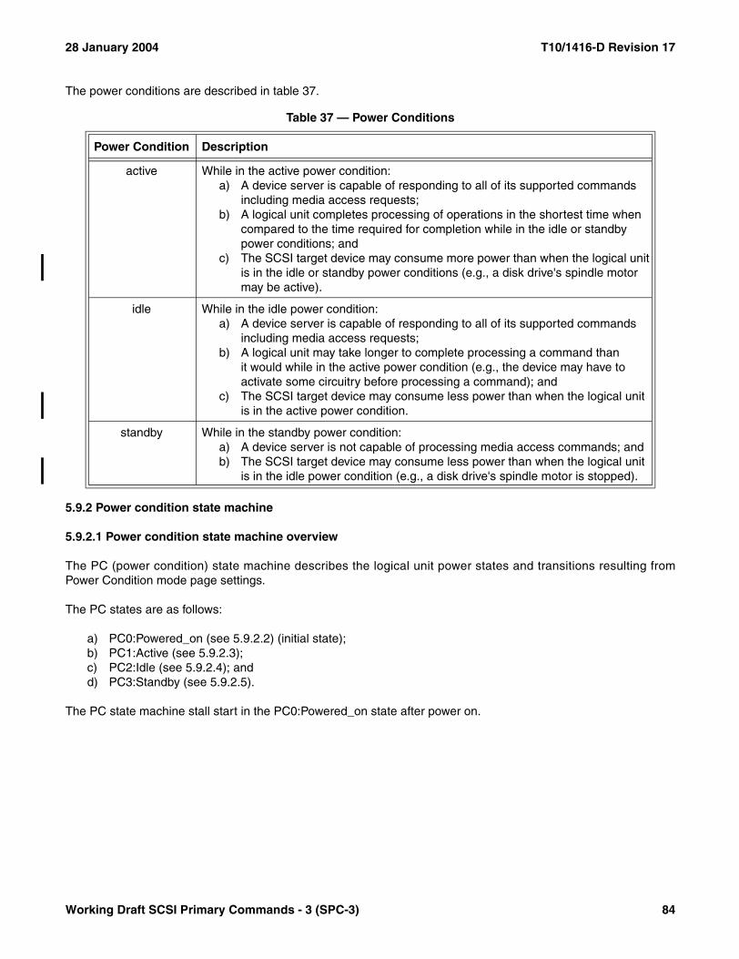
28 January 2004 T10/1416-D Revision 17
The power conditions are described in table 37.
5.9.2 Power condition state machine
5.9.2.1 Power condition state machine overview
The PC (power condition) state machine describes the logical unit power states and transitions resulting fromPower Condition mode page settings.
The PC states are as follows:
a) PC0:Powered_on (see 5.9.2.2) (initial state);b) PC1:Active (see 5.9.2.3);c) PC2:Idle (see 5.9.2.4); andd) PC3:Standby (see 5.9.2.5).
The PC state machine stall start in the PC0:Powered_on state after power on.
Table 37 — Power Conditions
Power Condition Description
active While in the active power condition:a) A device server is capable of responding to all of its supported commands
including media access requests;b) A logical unit completes processing of operations in the shortest time when
compared to the time required for completion while in the idle or standby power conditions; and
c) The SCSI target device may consume more power than when the logical unit is in the idle or standby power conditions (e.g., a disk drive's spindle motor may be active).
idle While in the idle power condition:a) A device server is capable of responding to all of its supported commands
including media access requests;b) A logical unit may take longer to complete processing a command than
it would while in the active power condition (e.g., the device may have to activate some circuitry before processing a command); and
c) The SCSI target device may consume less power than when the logical unit is in the active power condition.
standby While in the standby power condition:a) A device server is not capable of processing media access commands; andb) The SCSI target device may consume less power than when the logical unit
is in the idle power condition (e.g., a disk drive's spindle motor is stopped).
Working Draft SCSI Primary Commands - 3 (SPC-3) 84
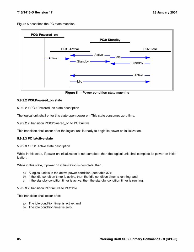
T10/1416-D Revision 17 28 January 2004
Figure 5 describes the PC state machine.
5.9.2.2 PC0:Powered_on state
5.9.2.2.1 PC0:Powered_on state description
The logical unit shall enter this state upon power on. This state consumes zero time.
5.9.2.2.2 Transition PC0:Powered_on to PC1:Active
This transition shall occur after the logical unit is ready to begin its power on initialization.
5.9.2.3 PC1:Active state
5.9.2.3.1 PC1:Active state description
While in this state, if power on initialization is not complete, then the logical unit shall complete its power on initial-ization.
While in this state, if power on initialization is complete, then:
a) A logical unit is in the active power condition (see table 37);b) If the idle condition timer is active, then the idle condition timer is running; andc) If the standby condition timer is active, then the standby condition timer is running.
5.9.2.3.2 Transition PC1:Active to PC2:Idle
This transition shall occur after:
a) The idle condition timer is active; andb) The idle condition timer is zero.
Figure 5 — Power condition state machine
PC2: IdlePC1: Active
PC3: Standby
Idle
Idle
PC0: Powered_on
Active
StandbyActive
Active
Standby
85 Working Draft SCSI Primary Commands - 3 (SPC-3)

28 January 2004 T10/1416-D Revision 17
5.9.2.3.3 Transition PC1:Active to PC3:Standby
This transition shall occur after:
a) The standby condition timer is active; andb) The standby condition timer is zero.
5.9.2.4 PC2:Idle state
5.9.2.4.1 PC2:Idle state description
While in this state:
a) A logical unit is in the idle power condition (see table 37); andb) If the standby condition timer is active, then the standby condition timer is running.
5.9.2.4.2 Transition PC2:Idle to PC1:Active
This transition shall occur after the device server receives a command that requires the logical unit to be in thePC1:Active state to process the command.
5.9.2.4.3 Transition PC2:Idle to PC3:Standby
This transition shall occur after:
a) The standby condition timer is active; andb) The standby condition timer is zero.
5.9.2.5 PC3:Standby state
5.9.2.5.1 PC3:Standby state description
While in this state, a logical unit is in the standby power condition (see table 37).
5.9.2.5.2 Transition PC3:Standby to PC1:Active
This transition shall occur after the device server receives a command that requires the logical unit to be in thePC1:Active state to process the command.
5.9.2.5.3 PC3:Standby to PC2:Idle
This transition shall occur after the device server receives a command that requires the logical unit to be in thePC2:Idle state to process the command.
5.10 Removable medium devices with an attached medium changer
When a logical unit is served by a medium changer, control over one medium transport element may be effectedusing medium changer commands sent to the device server within the logical unit. The level of control is not ascomplete as would be available if a fully functional medium-changer device server were implemented (see SMC).However, the amount of control is sufficient for paired device and medium changer configurations.
Working Draft SCSI Primary Commands - 3 (SPC-3) 86
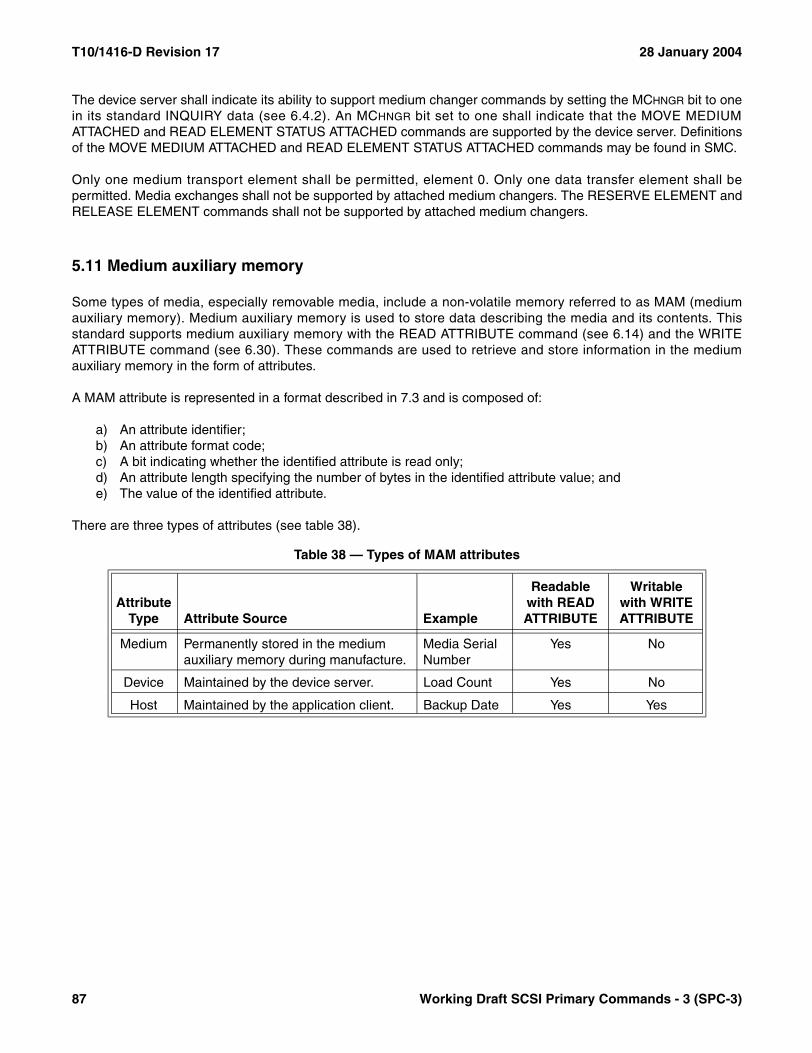
T10/1416-D Revision 17 28 January 2004
The device server shall indicate its ability to support medium changer commands by setting the MCHNGR bit to onein its standard INQUIRY data (see 6.4.2). An MCHNGR bit set to one shall indicate that the MOVE MEDIUMATTACHED and READ ELEMENT STATUS ATTACHED commands are supported by the device server. Definitionsof the MOVE MEDIUM ATTACHED and READ ELEMENT STATUS ATTACHED commands may be found in SMC.
Only one medium transport element shall be permitted, element 0. Only one data transfer element shall bepermitted. Media exchanges shall not be supported by attached medium changers. The RESERVE ELEMENT andRELEASE ELEMENT commands shall not be supported by attached medium changers.
5.11 Medium auxiliary memory
Some types of media, especially removable media, include a non-volatile memory referred to as MAM (mediumauxiliary memory). Medium auxiliary memory is used to store data describing the media and its contents. Thisstandard supports medium auxiliary memory with the READ ATTRIBUTE command (see 6.14) and the WRITEATTRIBUTE command (see 6.30). These commands are used to retrieve and store information in the mediumauxiliary memory in the form of attributes.
A MAM attribute is represented in a format described in 7.3 and is composed of:
a) An attribute identifier;b) An attribute format code;c) A bit indicating whether the identified attribute is read only;d) An attribute length specifying the number of bytes in the identified attribute value; ande) The value of the identified attribute.
There are three types of attributes (see table 38).
Table 38 — Types of MAM attributes
Attribute Type Attribute Source Example
Readable with READ ATTRIBUTE
Writable with WRITE ATTRIBUTE
Medium Permanently stored in the medium auxiliary memory during manufacture.
Media Serial Number
Yes No
Device Maintained by the device server. Load Count Yes No
Host Maintained by the application client. Backup Date Yes Yes
87 Working Draft SCSI Primary Commands - 3 (SPC-3)

28 January 2004 T10/1416-D Revision 17
Depending on that attribute type, attributes have the states shown in table 39.
Table 39 — MAM attribute states
Attribute Type Attribute State Description
Medium or Device
Read Only An application server may read the contents of the attribute with the READ ATTRIBUTE command, but an attempt to clear or change the attribute using the WRITE ATTRIBUTE command shall result in the command being termi-nated with a CHECK CONDITION status. When the READ ONLY bit (see 7.3.1) is one, the attribute is in the read only state.
Unsupported The device server does not support the attribute and shall not return it in response to a READ ATTRIBUTE command.
Host Nonexistent A host attribute does not exist in the medium auxiliary memory until a WRITE ATTRIBUTE command creates it.
Read/Write The attribute has been created using the WRITE ATTRIBUTE command. After the attribute has been created, the contents may be altered using subsequent WRITE ATTRIBUTE commands. A read/write attribute may be returned to the nonexistent state using a WRITE ATTRIBUTE command with the attribute length set to zero. When the READ ONLY bit (see 7.3.1) is zero, the attribute is in the read/write state.
Working Draft SCSI Primary Commands - 3 (SPC-3) 88

T10/1416-D Revision 17 28 January 2004
6 Commands for all device types
6.1 Summary of commands for all device types
The operation codes for commands that apply to all device types are listed in table 40.
Table 40 — Commands for all device types (part 1 of 2)
Command nameOperation
code Type Reference
ACCESS CONTROL IN 86h O 8.3.2ACCESS CONTROL OUT 87h O 8.3.3
CHANGE ALIASES A4h/0Bh b O 6.2EXTENDED COPY 83h O 6.3INQUIRY 12h M 6.4LOG SELECT 4Ch O 6.5LOG SENSE 4Dh O 6.6MODE SELECT(6) 15h C 6.7MODE SELECT(10) 55h C 6.8MODE SENSE(6) 1Ah C 6.9MODE SENSE(10) 5Ah C 6.10
MOVE MEDIUM ATTACHED a A7h C SMCPERSISTENT RESERVE IN 5Eh C 6.11PERSISTENT RESERVE OUT 5Fh C 6.12PREVENT ALLOW MEDIUM REMOVAL 1Eh C 6.13READ ATTRIBUTE 8Ch O 6.14READ BUFFER 3Ch O 6.15
READ ELEMENT STATUS ATTACHED a B4h C SMC
READ MEDIA SERIAL NUMBER ABh/01h b C 6.16RECEIVE COPY RESULTS 84h O 6.17RECEIVE DIAGNOSTIC RESULTS 1Ch O 6.18
REPORT ALIASES A3h/0Bh b O 6.19
REPORT DEVICE IDENTIFIER A3h/05h b O 6.20REPORT LUNS A0h X 6.21
REPORT SUPPORTED OPERATION CODES A3h/0Ch b O 6.22
REPORT SUPPORTED TASK MANAGEMENT FUNCTIONS A3h/0Dh b O 6.23
REPORT TARGET PORT GROUPS A3h/0Ah b O 6.24Type Key: C = Command implementation is defined in the applicable command standard (see 3.1.17).
M = Command implementation is mandatory.O = Command implementation is optional.X = Command implementation requirements given in referenced subclause of this standard.Z = Command implementation is defined in a previous standard.
a The MOVE MEDIUM ATTACHED and READ ELEMENT STATUS ATTACHED operation codes shown here should be used by devices with attached medium changers.
b This command is defined by a combination of operation code and service action. The operation code value is shown preceding the slash and the service action value is shown after the slash.
89 Working Draft SCSI Primary Commands - 3 (SPC-3)

28 January 2004 T10/1416-D Revision 17
REQUEST SENSE 03h C 6.25SEND DIAGNOSTIC 1Dh C 6.26
SET DEVICE IDENTIFIER A4h/06h b O 6.27
SET TARGET PORT GROUPS A4h/0Ah b O 6.28TEST UNIT READY 00h M 6.29WRITE ATTRIBUTE 8Dh O 6.30WRITE BUFFER 3Bh C 6.31Obsolete 16h ZObsolete 17h ZObsolete 18h ZObsolete 39h ZObsolete 3Ah ZObsolete 40h ZObsolete 56h ZObsolete 57h Z
Table 40 — Commands for all device types (part 2 of 2)
Command nameOperation
code Type Reference
Type Key: C = Command implementation is defined in the applicable command standard (see 3.1.17).M = Command implementation is mandatory.O = Command implementation is optional.X = Command implementation requirements given in referenced subclause of this standard.Z = Command implementation is defined in a previous standard.
a The MOVE MEDIUM ATTACHED and READ ELEMENT STATUS ATTACHED operation codes shown here should be used by devices with attached medium changers.
b This command is defined by a combination of operation code and service action. The operation code value is shown preceding the slash and the service action value is shown after the slash.
Working Draft SCSI Primary Commands - 3 (SPC-3) 90

T10/1416-D Revision 17 28 January 2004
6.2 CHANGE ALIASES command
6.2.1 CHANGE ALIASES command introduction
The CHANGE ALIASES command (see table 41) requests that the device server maintain and make changes to alist of associations between eight byte alias values and SCSI device or port designations. A designation contains aname and optional identifier information that specifies a SCSI device or port (see 6.2.2). The alias list may bequeried by the initiator via the REPORT ALIASES command (see 6.19). If the REPORT ALIASES command issupported then the CHANGE ALIASES command shall also be supported.
The CHANGE ALIASES command is a service action of the MAINTENANCE OUT command. Additional MAINTE-NANCE OUT service actions are defined in SCC-2 and in this standard. The MAINTENANCE OUT service actionsdefined in SCC-2 apply only to logical units that return a device type of 0Ch or the SCCS bit equal to one in theirstandard INQUIRY data (see 6.4.2).
The PARAMETER LIST LENGTH field specifies the length in bytes of the parameter data that shall be transferred fromthe application client to the device server. A parameter list length value of zero indicates that no data shall be trans-ferred and no changes shall be made in the alias list.
If the parameter list length results in the truncation of the header or any alias entry, then the device server shallmake no changes to the alias list and terminate the command with CHECK CONDITION status. The sense keyshall be set to ILLEGAL REQUEST and the additional sense code shall be set to PARAMETER LIST LENGTHERROR.
On successful completion of a CHANGE ALIASES command, the device server shall maintain an association ofeach assigned eight byte alias value to the SCSI device or port designation. These associations shall be cleared bya logical unit reset or I_T nexus loss. The device server shall maintain a separate alias list for each initiator.
A CHANGE ALIASES command may add, change or remove entries from the alias list. Alias list entries not refer-enced in the CHANGE ALIASES parameter data shall not be changed.
Table 41 — CHANGE ALIASES command
BitByte
7 6 5 4 3 2 1 0
0 OPERATION CODE (A4h)
1 Reserved SERVICE ACTION (0Bh)
2 Reserved
3 Reserved
4 Reserved
5 Reserved
6 (MSB)
PARAMETER LIST LENGTH7
8
9 (LSB)
10 Reserved
11 CONTROL
91 Working Draft SCSI Primary Commands - 3 (SPC-3)

28 January 2004 T10/1416-D Revision 17
NOTE 10 - An application client may use alias values to reference SCSI devices or ports in third party commands(e.g., EXTENDED COPY). The alias list provides a mechanism for eight byte third party identifier fields to referencea third party device or port whose name or addressing information is longer than eight bytes. For example, an appli-cation may use the CHANGE ALIASES command to establish an association between an alias value and a SCSItarget device or SCSI target port designation. Then, it may send an EXTENDED COPY command containing in theparameter data an alias target descriptor (see 6.3.6.3) that includes this alias value. At the completion of theEXTENDED COPY command the application should clear this entry from the device server’s alias list by sending aCHANGE ALIASES command that requests association of the alias value to a NULL DESIGNATION (see 6.2.4.2)alias format.
If the device server has insufficient resources to make all requested changes to the alias list, the device server shallmake no changes to the alias list and shall terminate the command with CHECK CONDITION status. The sensekey shall be set to ILLEGAL REQUEST and additional sense code shall be set to INSUFFICIENT RESOURCES.
The parameter data for a CHANGE ALIASES command (see table 42) contains zero or more alias entries. If thedevice server processes a CHANGE ALIASES command that contains at least one alias entry while there existsany other enabled task that references an alias entry in the alias list, the device server shall terminate theCHANGE ALIASES command with CHECK CONDITION status. The sense key shall be set to ILLEGALREQUEST and the additional sense code shall be set to OPERATION IN PROGRESS.
The PARAMETER DATA LENGTH field should contain the number of bytes of attribute data and should be ignored bythe device server.
The format of an alias entry is described in 6.2.2.
Table 42 — CHANGE ALIASES parameter list
BitByte
7 6 5 4 3 2 1 0
0 (MSB)PARAMETER DATA LENGTH (n-3)
3 (LSB)
4Reserved
7
Alias entry (or entries)
8Alias entry 0 (see 6.2.2)
.
.
.
Alias entry x (see 6.2.2)n
Working Draft SCSI Primary Commands - 3 (SPC-3) 92
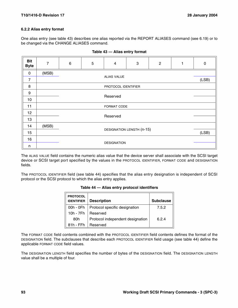
T10/1416-D Revision 17 28 January 2004
6.2.2 Alias entry format
One alias entry (see table 43) describes one alias reported via the REPORT ALIASES command (see 6.19) or tobe changed via the CHANGE ALIASES command.
The ALIAS VALUE field contains the numeric alias value that the device server shall associate with the SCSI targetdevice or SCSI target port specified by the values in the PROTOCOL IDENTIFIER, FORMAT CODE and DESIGNATION
fields.
The PROTOCOL IDENTIFIER field (see table 44) specifies that the alias entry designation is independent of SCSIprotocol or the SCSI protocol to which the alias entry applies.
The FORMAT CODE field contents combined with the PROTOCOL IDENTIFIER field contents defines the format of theDESIGNATION field. The subclauses that describe each PROTOCOL IDENTIFIER field usage (see table 44) define theapplicable FORMAT CODE field values.
The DESIGNATION LENGTH field specifies the number of bytes of the DESIGNATION field. The DESIGNATION LENGTH
value shall be a multiple of four.
Table 43 — Alias entry format
BitByte
7 6 5 4 3 2 1 0
0 (MSB)ALIAS VALUE
7 (LSB)
8 PROTOCOL IDENTIFIER
9Reserved
10
11 FORMAT CODE
12Reserved
13
14 (MSB)DESIGNATION LENGTH (n-15)
15 (LSB)
16DESIGNATION
n
Table 44 — Alias entry protocol identifiers
PROTOCOL IDENTIFIER Description Subclause
00h - 0Fh Protocol specific designation 7.5.2
10h - 7Fh Reserved
80h Protocol independent designation 6.2.4
81h - FFh Reserved
93 Working Draft SCSI Primary Commands - 3 (SPC-3)
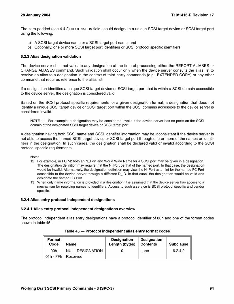
28 January 2004 T10/1416-D Revision 17
The zero-padded (see 4.4.2) DESIGNATION field should designate a unique SCSI target device or SCSI target portusing the following:
a) A SCSI target device name or a SCSI target port name, andb) Optionally, one or more SCSI target port identifiers or SCSI protocol specific identifiers.
6.2.3 Alias designation validation
The device server shall not validate any designation at the time of processing either the REPORT ALIASES orCHANGE ALIASES command. Such validation shall occur only when the device server consults the alias list toresolve an alias to a designation in the context of third-party commands (e.g., EXTENDED COPY) or any othercommand that requires reference to the alias list.
If a designation identifies a unique SCSI target device or SCSI target port that is within a SCSI domain accessibleto the device server, the designation is considered valid.
Based on the SCSI protocol specific requirements for a given designation format, a designation that does notidentify a unique SCSI target device or SCSI target port within the SCSI domains accessible to the device server isconsidered invalid.
NOTE 11 - For example, a designation may be considered invalid if the device server has no ports on the SCSIdomain of the designated SCSI target device or SCSI target port.
A designation having both SCSI name and SCSI identifier information may be inconsistent if the device server isnot able to access the named SCSI target device or SCSI target port through one or more of the names or identi-fiers in the designation. In such cases, the designation shall be declared valid or invalid according to the SCSIprotocol specific requirements.
Notes12 For example, in FCP-2 both an N_Port and World Wide Name for a SCSI port may be given in a designation.
The designation definition may require that the N_Port be that of the named port. In that case, the designationwould be invalid. Alternatively, the designation definition may view the N_Port as a hint for the named FC Portaccessible to the device server through a different D_ID. In that case, the designation would be valid anddesignate the named FC Port.
13 When only name information is provided in a designation, it is assumed that the device server has access to amechanism for resolving names to identifiers. Access to such a service is SCSI protocol specific and vendorspecific.
6.2.4 Alias entry protocol independent designations
6.2.4.1 Alias entry protocol independent designations overview
The protocol independent alias entry designations have a protocol identifier of 80h and one of the format codesshown in table 45.
Table 45 — Protocol independent alias entry format codes
Format Code Name
Designation Length (bytes)
Designation Contents Subclause
00h NULL DESIGNATION 0 none 6.2.4.2
01h - FFh Reserved
Working Draft SCSI Primary Commands - 3 (SPC-3) 94
T10/1416-D Revision 17 28 January 2004
6.2.4.2 NULL DESIGNATION alias format
In response to an alias entry with the NULL DESIGNATION format, the device sever shall remove the specifiedalias value from the alias list. Application clients should use the NULL DESIGNATION format in a CHANGEALIASES command to remove an alias entry from the alias list when that alias entry is no longer needed. TheNULL DESIGNATION format shall not appear in REPORT ALIASES parameter data.
95 Working Draft SCSI Primary Commands - 3 (SPC-3)

28 January 2004 T10/1416-D Revision 17
6.3 EXTENDED COPY command
6.3.1 EXTENDED COPY command introduction
The EXTENDED COPY command (see table 46) provides a means to copy data from one set of logical units toanother set of logical units or to the same set of logical units. The entity within a SCSI device that receives andperforms the EXTENDED COPY command is called the copy manager. The copy manager is responsible forcopying data from the source devices to the destination devices. The copy source and destination devices arelogical units that may reside in different SCSI devices or the same SCSI device. It is possible that the copy sourcedevice, copy destination device, and the copy manager are the same logical unit.
Before the copy manager is instructed to move data, the application controlling the data movement shall indepen-dently take any necessary actions required to prepare the source and destination devices for the EXTENDEDCOPY command. These actions may include media changer commands, loading of tapes, MODE SELECTcommands, reservation commands, positioning of tape, etc. After all preparatory actions have been accomplished,the EXTENDED COPY command should be issued to the copy manager to start the data transfer.
The PARAMETER LIST LENGTH field specifies the length in bytes of the parameter data that shall be contained in theData-Out Buffer. A parameter list length of zero indicates that copy manager shall not transfer any data or alter anyinternal state; this shall not be considered an error. If the parameter list length causes truncation of the parameterlist in a target descriptor or segment descriptor, no data shall be transferred and the EXTENDED COPY commandshall be terminated with a CHECK CONDITION status. The sense key shall be set to ILLEGAL REQUEST and theadditional sense code shall be set to PARAMETER LIST LENGTH ERROR.
Table 46 — EXTENDED COPY command
BitByte
7 6 5 4 3 2 1 0
0 OPERATION CODE (83h)
1 Reserved
2 Reserved
3 Reserved
4 Reserved
5 Reserved
6 Reserved
7 Reserved
8 Reserved
9 Reserved
10 (MSB)
PARAMETER LIST LENGTH11
12
13 (LSB)
14 Reserved
15 CONTROL
Working Draft SCSI Primary Commands - 3 (SPC-3) 96
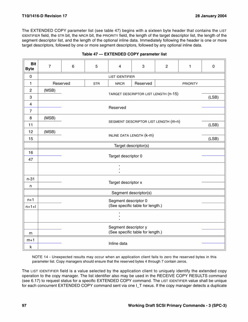
T10/1416-D Revision 17 28 January 2004
The EXTENDED COPY parameter list (see table 47) begins with a sixteen byte header that contains the LIST
IDENTIFIER field, the STR bit, the NRCR bit, the PRIORITY field, the length of the target descriptor list, the length of thesegment descriptor list, and the length of the optional inline data. Immediately following the header is one or moretarget descriptors, followed by one or more segment descriptors, followed by any optional inline data.
NOTE 14 - Unexpected results may occur when an application client fails to zero the reserved bytes in thisparameter list. Copy managers should ensure that the reserved bytes 4 through 7 contain zeros.
The LIST IDENTIFIER field is a value selected by the application client to uniquely identify the extended copyoperation to the copy manager. The list identifier also may be used in the RECEIVE COPY RESULTS command(see 6.17) to request status for a specific EXTENDED COPY command. The LIST IDENTIFIER value shall be uniquefor each concurrent EXTENDED COPY command sent via one I_T nexus. If the copy manager detects a duplicate
Table 47 — EXTENDED COPY parameter list
BitByte
7 6 5 4 3 2 1 0
0 LIST IDENTIFIER
1 Reserved STR NRCR Reserved PRIORITY
2 (MSB)TARGET DESCRIPTOR LIST LENGTH (n-15)
3 (LSB)
4Reserved
7
8 (MSB)SEGMENT DESCRIPTOR LIST LENGTH (m-n)
11 (LSB)
12 (MSB)INLINE DATA LENGTH (k-m)
15 (LSB)
Target descriptor(s)
16Target descriptor 0
47...
n-31Target descriptor x
n
Segment descriptor(s)
n+1 Segment descriptor 0(See specific table for length.)n+1+l
.
.
.
Segment descriptor y(See specific table for length.)m
m+1Inline data
k
97 Working Draft SCSI Primary Commands - 3 (SPC-3)

28 January 2004 T10/1416-D Revision 17
LIST IDENTIFIER value the command shall be terminated with a CHECK CONDITION status, the sense key shall beset to ILLEGAL REQUEST and the additional sense code shall be set to OPERATION IN PROGRESS.
The PRIORITY field establishes the priority of data transfer operations resulting from this EXTENDED COPYcommand relative to data transfer operations resulting from other commands being executed by the same deviceserver. All commands other than copy commands have a priority of 1h. Priority 0h is the highest priority, withincreasing PRIORITY values indicating lower priorities.
A Sequential Striped (STR) bit set to one indicates to the copy manager that the majority of the disk references inthe parameter list represent sequential access of several striped disks. This may be used by the copy manager toperform read operations from a source disk at any time and in any order during processing of an EXTENDEDCOPY command as described in 6.3.6.4. A STR bit set to zero indicates to the copy manager that disk referencesare not necessarily sequential.
If the No Receive Copy Results (NRCR) bit is set to zero, the copy manager shall hold data for retrieval by the appli-cation client using the RECEIVE COPY RESULTS command with the RECEIVE DATA service action (see 6.17.3)and specified by the segment descriptors. If NRCR is one, the copy manager may discard all data accessible to theapplication client via the RECEIVE COPY RESULTS command with the RECEIVE DATA service action. If the appli-cation client requests delivery of data that has been discarded as a result of NRCR being one, the copy managershall respond as if the EXTENDED COPY command has not been processed.
The TARGET DESCRIPTOR LIST LENGTH contains the length in bytes of the target descriptor list that immediatelyfollows the parameter list header. The number of target descriptors equals the length in bytes of the targetdescriptor list divided by 32.
An EXTENDED COPY command may reference one or more copy target devices (the name given by theEXTENDED COPY command description to source and/or the destination logical units). Each copy target device isdescribed by a target descriptor. All target descriptors have their formats specified by an EXTENDED COPYdescriptor code. A copy manager may not support all target descriptor formats and shall list all target descriptorformats supported in response to the RECEIVE COPY RESULTS command with OPERATING PARAMETERSservice action (see 6.17.4). See 6.3.6 for a detailed description of the target descriptors.
Segment descriptors reference target descriptors by their position, or index, in the target descriptor list. The indexfor a target descriptor is computed by subtracting 16 from the starting byte number for the target descriptor in theparameter data and dividing the result by 32. The maximum number of target descriptors permitted within aparameter list is indicated by the MAXIMUM TARGET COUNT field in the copy manager’s operating parameters (see6.17.4). If the number of target descriptors exceeds the allowed number, the command shall be terminated withCHECK CONDITION status. The sense key shall be set to ILLEGAL REQUEST and the additional sense codeshall be set to TOO MANY TARGET DESCRIPTORS.
The SEGMENT DESCRIPTOR LIST LENGTH contains the length in bytes of the segment descriptor list that follows thetarget descriptors. See 6.3.7 for a detailed description of the segment descriptors. The maximum number ofsegment descriptors permitted within a parameter list is indicated by the MAXIMUM SEGMENT COUNT field in the copymanager’s operating parameters (see 6.17.4). If the number of segment descriptors exceeds the allowed number,the command shall be terminated with CHECK CONDITION status. The sense key shall be set to ILLEGALREQUEST and the additional sense code shall be set to TOO MANY SEGMENT DESCRIPTORS.
The maximum length of the target and segment descriptors permitted within a parameter list is indicated by theMAXIMUM DESCRIPTOR LIST LENGTH field in the copy manager’s operating parameters (see 6.17.4). If the combinedlength of the target and segment descriptors exceeds the allowed value, the command shall be terminated withCHECK CONDITION status. The sense key shall be set to ILLEGAL REQUEST and the additional sense codeshall be set to PARAMETER LIST LENGTH ERROR.
Working Draft SCSI Primary Commands - 3 (SPC-3) 98
T10/1416-D Revision 17 28 January 2004
The INLINE DATA LENGTH field contains the number of bytes of inline data, after the last segment descriptor. A valueof zero indicates that no inline data is present.
The copy manager shall move data from the source devices to the destination devices as prescribed by thesegment descriptors. The specific commands issued by the copy manager to the source and destination deviceswhile processing the segment descriptors is vendor specific. Upon completion of an EXTENDED COPY commandthat returns GOOD status, the source and destination devices, particularly stream devices, shall be positioned atdeterministic locations such that the device may be repositioned to the same location by the application client withappropriate commands.
6.3.2 Errors detected before starting processing of the segment descriptors
Errors may occur during processing of an EXTENDED COPY command before the first segment descriptor isprocessed. These conditions include CRC or parity errors while transferring the EXTENDED COPY command,invalid parameters in the CDB or parameter data, invalid segment descriptors, and inability of the copy manager tocontinue operating. In the event of such an exception condition, the copy manager shall:
a) Terminate the EXTENDED COPY command with CHECK CONDITION status; andb) Set the VALID bit in the sense data to zero. The sense key shall contain the sense key code describing the
exception condition (i.e.: not COPY ABORTED).
6.3.3 Errors detected during processing of segment descriptors
Errors may occur after the copy manager has begun processing segment descriptors. These include invalid param-eters in segment descriptors, invalid segment descriptors, unavailable targets referenced by target descriptors,inability of the copy manager to continue operating, and errors reported by source or destination copy targetdevices. If the copy manager receives a CHECK CONDITION status from one of the copy target devices, it shallrecover the sense data associated with the exception condition and clear any ACA condition associated with theCHECK CONDITION status.
If processing of a segment cannot complete because the copy manager is unable to establish communications witha copy target device, or because the copy target device does not respond to INQUIRY, or because the datareturned in response to INQUIRY indicates an unsupported logical unit, then the EXTENDED COPY commandshall be terminated with a CHECK CONDITION status. The sense key shall be set to COPY ABORTED and theadditional sense code shall be set to COPY TARGET DEVICE NOT REACHABLE.
If processing of a segment cannot complete because the data returned in response to an INQUIRY commandindicates a device type that does not match the type in the target descriptor, then the EXTENDED COPY commandshall be terminated with a CHECK CONDITION status. The sense key shall be set to COPY ABORTED and theadditional sense code shall be set to INCORRECT COPY TARGET DEVICE TYPE.
If the copy manager has issued a command other than INQUIRY to a copy target device while processing anEXTENDED COPY command and the copy target device either fails to respond with status or responds with statusother than BUSY, TASK SET FULL, ACA ACTIVE, or RESERVATION CONFLICT the condition shall be considereda copy target device command failure. In response to a copy target device command failure the EXTENDED COPYcommand shall be terminated with a CHECK CONDITION status. The sense key shall be set to COPY ABORTEDand the additional sense code shall be set to THIRD PARTY DEVICE FAILURE.
If a copy target device responds to a command from the copy manager with a status of BUSY, TASK SET FULL,ACA ACTIVE, or RESERVATION CONFLICT the copy manager shall either retry the command or terminate theEXTENDED COPY command as a copy target device command failure.
99 Working Draft SCSI Primary Commands - 3 (SPC-3)

28 January 2004 T10/1416-D Revision 17
NOTES15 The copy manager is assumed to employ a vendor specific retry policy that minimizes time consuming and/or
fruitless repetition of retries.16 RESERVATION CONFLICT status is listed only to give the copy manager leeway in multi-port cases. The copy
manager may have multiple initiator ports that are capable of reaching a copy target device, and there may bea third-party reservation for one of these initiator ports. The copy manager may need to try access frommultiple initiator ports to find one with access.
If a copy target device responds to an input or output operation with a GOOD status but less data than expected istransferred, then the EXTENDED COPY command shall be terminated with a CHECK CONDITION status. Thesense key shall be set to COPY ABORTED and additional sense code shall be set to COPY TARGET DEVICEDATA UNDERRUN. If an overrun is detected, then the EXTENDED COPY command shall be terminated with aCHECK CONDITION status. The sense key shall be set to COPY ABORTED and additional sense code shall beset to COPY TARGET DEVICE DATA OVERRUN.
Following an exception condition detected during segment descriptor processing:
a) The copy manager shall terminate the EXTENDED COPY command with CHECK CONDITION status;b) The copy manager shall set the sense key code to COPY ABORTED;c) The copy manager shall indicate the segment that was being processed at the time of the exception by
writing the segment number to the third and forth bytes of the COMMAND-SPECIFIC INFORMATION field. Thesegment number is based on the relative position of the segment descriptor in the EXTENDED COPYparameter list. The first segment descriptor in the parameter list is assigned descriptor number zero, thesecond is assigned one, etc.;
d) If any data has been written to the destination for the segment being processed at the time the erroroccurred, the residual for the segment shall be placed in the INFORMATION field, and the VALID bit shall beset to one. The residual count shall be reported in bytes if the peripheral device type in the destinationtarget descriptor is 03h (i.e., processor device), and in destination device blocks for all other device typecodes. The residual count shall be computed by subtracting the number of bytes or blocks successfullywritten during the processing of the current segment from the number of bytes or blocks which would havebeen written if all commands had completed with GOOD status and all READ commands had returned thefull data length requested. When computing the residual count, the copy manager shall include only theresults of commands successfully completed by a destination device, specifically commands completed bya destination device with a GOOD status or with a CHECK CONDITION status and the EOM bit set to onein the sense data. If the copy manager has used out of order transfers the residual count shall be basedsolely on the contiguous successfully completed transfers starting at relative byte zero of the segment (i.e.,any successfully completed transfers farther from relative byte zero than the first incomplete or unsuc-cessful transfer shall not contribute to the computation of the residual count). If no data has been written tothe destination for the segment being processed at the time the error occurred, then the VALID bit shall beset to zero and the contents of the INFORMATION field are not defined. Segment descriptors that do notspecify a transfer count shall not have a valid residual count returned;
e) If the exception condition is reported by the source logical unit, then the first byte of the COMMAND-SPECIFIC
INFORMATION field shall specify the starting byte number, relative to the first byte of sense data, of an areathat contains the status byte and sense data delivered to the copy manager by the source logical unit. Thestatus byte and sense data shall not be modified by the copy manager or device server. A zero valueindicates that no status byte and sense data is being returned for the source logical unit;
f) If the exception condition is reported by the destination logical unit, then the second byte of theCOMMAND-SPECIFIC INFORMATION field shall specify the starting byte number, relative to the first byte ofsense data, of an area that contains the status byte and sense data delivered to the copy manager by thedestination logical unit. The status byte and sense data shall not be modified by the copy manager ordevice server. A zero value indicates that no status byte and sense data is being returned for the desti-nation logical unit;
Working Draft SCSI Primary Commands - 3 (SPC-3) 100

T10/1416-D Revision 17 28 January 2004
g) If segment processing is terminated because a copy target device is unreachable or as the result of atarget command failure, then the SENSE-KEY SPECIFIC field shall be set as described in 4.5.2.4.5, with theFIELD POINTER field indicating the first byte of the target descriptor that identifies the target; and
h) If, during the processing of a segment descriptor, the copy manager detects an error in the segmentdescriptor, then the SENSE-KEY SPECIFIC field shall be set as described in 4.5.2.4.5, with the FIELD POINTER
field indicating the byte in error. The FIELD POINTER field may be used to indicate an offset into either theparameter data or the segment descriptor. The SD bit is used to differentiate between these two cases. TheSD bit shall be set to zero to indicate the FIELD POINTER field contains an offset from the start of theparameter data. The SD bit shall be set to one to indicate the FIELD POINTER field contains an offset from thestart of the segment descriptor; and
i) The copy manager shall preserve information for the FAILED SEGMENT DETAILS service action of theRECEIVE COPY RESULTS command (see 6.17.5). The information shall be discarded as described in6.17.5.
6.3.4 Abort task management functions
When a device server processes an ABORT TASK, ABORT TASK SET, or CLEAR TASK SET task managementfunction that terminates an EXTENDED COPY command, the copy manager shall ensure that all commands anddata transfers generated by the terminated EXENDED COPY command have been terminated and are no longertransferring data before allowing the task manager to complete the task management function. This requirementshall also apply to the processing the PREEMPT AND ABORT service action of the PERSISTENT RESERVE OUTcommand as described in 5.6.8.5.
101 Working Draft SCSI Primary Commands - 3 (SPC-3)

28 January 2004 T10/1416-D Revision 17
6.3.5 Descriptor type codes
Target descriptors and segment descriptors share a single set of code values that identify the type of descriptor(see table 48). Segment descriptors use codes in the range 00h to BFh. The definitions of codes between C0h andDFh are vendor specific. Target descriptors use codes in the range E0h to FFh.
Table 48 — EXTENDED COPY descriptor type codes (part 1 of 2)
Descriptortype code Reference Description a Shorthand a
00h 6.3.7.3 Copy from block device to stream device block→ stream
01h 6.3.7.4 Copy from stream device to block device stream→ block
02h 6.3.7.5 Copy from block device to block device block→ block
03h 6.3.7.6 Copy from stream device to stream device stream→ stream
04h 6.3.7.7 Copy inline data to stream device inline→ stream
05h 6.3.7.8 Copy embedded data to stream device embedded→ stream
06h 6.3.7.9 Read from stream device and discard stream→ discard
07h 6.3.7.10 Verify block or stream device operation
08h 6.3.7.11 Copy block device with offset to stream device block<o>→ stream
09h 6.3.7.12 Copy stream device to block device with offset stream→ block<o>
0Ah 6.3.7.13Copy block device with offset to block device with off-set
block<o>→ block<o>
0Bh 6.3.7.3Copy from block device to stream device and hold a
copy of processed data for the application client bblock→ stream +appli-cation client
0Ch 6.3.7.4Copy from stream device to block device and hold a
copy of processed data for the application client bstream→ block +appli-cation client
0Dh 6.3.7.5Copy from block device to block device and hold a
copy of processed data for the application client bblock→ block +appli-cation client
0Eh 6.3.7.6Copy from stream device to stream device and hold
a copy of processed data for the application client bstream→ stream +application client
0Fh 6.3.7.9Read from stream device and hold a copy of
processed data for the application client bstream→ discard +application client
10h 6.3.7.14 Write filemarks to sequential-access device filemark→ tape
11h 6.3.7.15Space records or filemarks on sequential-access device
space→ tape
12h 6.3.7.16 Locate on sequential-access device locate→ tape
a Block devices are those with peripheral device type codes 0h (i.e, direct-access), 4h (i.e., write-once), 5h (i.e., CD/DVD), 7h (i.e., optical memory), and Eh (i.e., simplified direct-access). Stream devices are those devices with peripheral device type codes 1h (i.e., sequential-access) and 3h (i.e., processor). Sequential-access stream (indicated by "tape" in the shorthand column) devices are those with peripheral device type code 1h. See 6.4.2 for peripheral device type code definitions.
b The application client shall use the RECEIVE COPY RESULTS with a RECEIVE DATA service action to retrieve data held for it by the copy manager (see 6.17.3).
Working Draft SCSI Primary Commands - 3 (SPC-3) 102
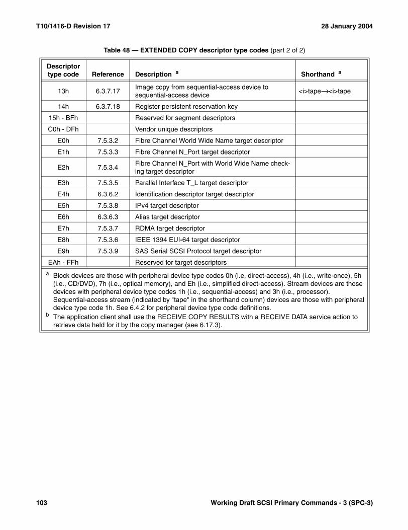
T10/1416-D Revision 17 28 January 2004
13h 6.3.7.17Image copy from sequential-access device to sequential-access device
<i>tape→ <i>tape
14h 6.3.7.18 Register persistent reservation key
15h - BFh Reserved for segment descriptors
C0h - DFh Vendor unique descriptors
E0h 7.5.3.2 Fibre Channel World Wide Name target descriptor
E1h 7.5.3.3 Fibre Channel N_Port target descriptor
E2h 7.5.3.4Fibre Channel N_Port with World Wide Name check-ing target descriptor
E3h 7.5.3.5 Parallel Interface T_L target descriptor
E4h 6.3.6.2 Identification descriptor target descriptor
E5h 7.5.3.8 IPv4 target descriptor
E6h 6.3.6.3 Alias target descriptor
E7h 7.5.3.7 RDMA target descriptor
E8h 7.5.3.6 IEEE 1394 EUI-64 target descriptor
E9h 7.5.3.9 SAS Serial SCSI Protocol target descriptor
EAh - FFh Reserved for target descriptors
Table 48 — EXTENDED COPY descriptor type codes (part 2 of 2)
Descriptortype code Reference Description a Shorthand a
a Block devices are those with peripheral device type codes 0h (i.e, direct-access), 4h (i.e., write-once), 5h (i.e., CD/DVD), 7h (i.e., optical memory), and Eh (i.e., simplified direct-access). Stream devices are those devices with peripheral device type codes 1h (i.e., sequential-access) and 3h (i.e., processor). Sequential-access stream (indicated by "tape" in the shorthand column) devices are those with peripheral device type code 1h. See 6.4.2 for peripheral device type code definitions.
b The application client shall use the RECEIVE COPY RESULTS with a RECEIVE DATA service action to retrieve data held for it by the copy manager (see 6.17.3).
103 Working Draft SCSI Primary Commands - 3 (SPC-3)

28 January 2004 T10/1416-D Revision 17
6.3.6 Target descriptors
6.3.6.1 Target descriptors introduction
All target descriptors are 32 bytes in length and begin with a four-byte header (see table 49) containing theDESCRIPTOR TYPE CODE field that identifies the format of the descriptor. The assigned descriptor type code valuesare shown in table 48. Support for each target descriptor format is optional. If a copy manager receives an unsup-ported descriptor type code in a target descriptor, the command shall be terminated with CHECK CONDITIONstatus. The sense key shall be set to ILLEGAL REQUEST and the additional sense code shall be set to UNSUP-PORTED TARGET DESCRIPTOR TYPE CODE.
The DESCRIPTOR TYPE CODE field is described in 6.3.5.
The LU ID TYPE field (see table 50) specifies the interpretation of the LU IDENTIFIER field in target descriptors thatcontain a LU IDENTIFIER field.
Support for LU ID type codes other than 00b is optional. If a copy manager receives an unsupported LU ID typecode, the command shall be terminated with a CHECK CONDITION status. The sense key shall be set to ILLEGALREQUEST and the additional sense code shall be set to INVALID FIELD IN PARAMETER LIST.
If the LU ID TYPE field specifies that the LU IDENTIFIER field contains a logical unit number, then the LU IDENTIFIER fieldspecifies the logical unit within the SCSI device specified by other fields in the target descriptor that shall be thesource or destination for EXTENDED COPY operations.
If the LU ID TYPE field specifies that the LU IDENTIFIER field contains a proxy token (see 8.3.1.6.2), then the copymanager shall use the LU IDENTIFIER field contents to obtain proxy access rights to the logical unit associated withthe proxy token. The logical unit number that represents the proxy access rights shall be the source or destinationfor EXTENDED COPY operations.
Table 49 — Target descriptor format
BitByte
7 6 5 4 3 2 1 0
0 DESCRIPTOR TYPE CODE (E0h - FFh)
1 LU ID TYPE NUL PERIPHERAL DEVICE TYPE
2 Reserved
3 Reserved
4Target descriptor parameters
27
28Device type specific parameters
31
Table 50 — LU ID type codes
Code LU IDENTIFIER field contents Reference
00b Logical Unit Number SAM-201b Proxy Token 8.3.1.6.2
10b - 11b Reserved
Working Draft SCSI Primary Commands - 3 (SPC-3) 104

T10/1416-D Revision 17 28 January 2004
The copy manager should obtain a LUN value for addressing this logical unit by sending an ACCESS CONTROLOUT command with ASSIGN PROXY LUN service action (see 8.3.3.11) to the access controls coordinator of theSCSI device that is identified by other fields in the target descriptor. The copy manager shall use a LUN assignedon the basis of a proxy token only for those commands that are necessary for the processing of the EXTENDEDCOPY command whose parameter data contains the proxy token. When the copy manager has completedEXTENDED COPY commands involving a proxy token, the copy manager should release the LUN value using anACCESS CONTROL OUT command with RELEASE PROXY LUN service action (see 8.3.3.12).
EXTENDED COPY access to proxy logical units is to be accomplished only via LU ID type 01b. If the copymanager receives a target descriptor containing LU ID type 00b and a logical unit number matching a LUN valuethat the copy manager has obtained using an ACCESS CONTROL OUT command with ASSIGN PROXY LUNservice action, the EXTENDED COPY command shall be terminated with a CHECK CONDITION status, the sensekey shall be set to COPY ABORTED and the additional sense code shall be set to COPY TARGET DEVICE NOTREACHABLE.
A null device (NUL) bit set to zero indicates that the target descriptor identifies a SCSI device that is expected torespond to an INQUIRY command and to which data movement commands may be sent. A NUL bit set to oneindicates that the descriptor identifies a null device that is not expected to be the recipient of any SCSI commands.If NUL is one, bytes 4-27 of the target descriptor shall be ignored. If the processing required by a segmentdescriptor necessitates sending a command to a copy target device whose target descriptor has the NUL bit set toone, then the EXTENDED COPY command shall be terminated as if an unreachable target had been encountered(see 6.3.3).
NOTE 17 - Target descriptors with the NUL bit set to one are useful for processing the residual data from previoussegment descriptors without affecting any media. For example, a segment descriptor of type 06h (stream device todiscard) with a byte count of zero, CAT equal to zero, and a null source target descriptor with PAD equal to one maybe used to discard all residual data.
The PERIPHERAL DEVICE TYPE field is described in 6.4.2. The value in the DESCRIPTOR TYPE CODE field determinesthe format of the target descriptor parameters that follow the four-byte header and precede the device type specificparameters. The values in the DESCRIPTOR TYPE CODE field are listed in table 48.
The value in the PERIPHERAL DEVICE TYPE field determines the format of the device type specific parameters thatfollow the target descriptor parameters. The device type specific parameters convey information specific to the typeof device identified by the target descriptor.
Table 51 lists the peripheral device type code values having formats defined for the device type specific parametersin a target descriptor. Peripheral device types with code values not listed in table 51 are reserved in theEXTENDED COPY parameter list.
The copy manager may, as part of processing a segment descriptor, verify the information in a target descriptor’sdevice specific fields. However, when verifying the information, the copy manager shall not issue any commandsthat change the position of read/write media on the target without restoring it. Any errors encountered whileverifying the information shall be handled as described in 6.3.3.
Table 51 — Device type specific parameters in target descriptors
PeripheralDevice Type Reference Description Shorthand
00h, 04h, 05h, 07h, and 0Eh 6.3.6.4 Block devices Block
01h 6.3.6.5 Sequential-access devices Stream or Tape
03h 6.3.6.6 Processor devices Stream
105 Working Draft SCSI Primary Commands - 3 (SPC-3)
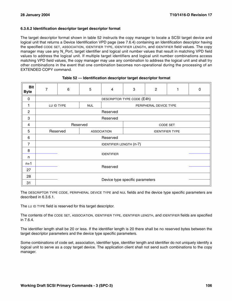
28 January 2004 T10/1416-D Revision 17
6.3.6.2 Identification descriptor target descriptor format
The target descriptor format shown in table 52 instructs the copy manager to locate a SCSI target device andlogical unit that returns a Device Identification VPD page (see 7.6.4) containing an Identification descriptor havingthe specified CODE SET, ASSOCIATION, IDENTIFIER TYPE, IDENTIFIER LENGTH, and IDENTIFIER field values. The copymanager may use any N_Port, target identifier and logical unit number values that result in matching VPD fieldvalues to address the logical unit. If multiple target identifiers and logical unit number combinations accessmatching VPD field values, the copy manager may use any combination to address the logical unit and shall tryother combinations in the event that one combination becomes non-operational during the processing of anEXTENDED COPY command.
The DESCRIPTOR TYPE CODE, PERIPHERAL DEVICE TYPE and NUL fields and the device type specific parameters aredescribed in 6.3.6.1.
The LU ID TYPE field is reserved for this target descriptor.
The contents of the CODE SET, ASSOCIATION, IDENTIFIER TYPE, IDENTIFIER LENGTH, and IDENTIFIER fields are specifiedin 7.6.4.
The identifier length shall be 20 or less. If the identifier length is 20 there shall be no reserved bytes between thetarget descriptor parameters and the device type specific parameters.
Some combinations of code set, association, identifier type, identifier length and identifier do not uniquely identify alogical unit to serve as a copy target device. The application client shall not send such combinations to the copymanager.
Table 52 — Identification descriptor target descriptor format
BitByte
7 6 5 4 3 2 1 0
0 DESCRIPTOR TYPE CODE (E4h)
1 LU ID TYPE NUL PERIPHERAL DEVICE TYPE
2 Reserved
3 Reserved
4 Reserved CODE SET
5 Reserved ASSOCIATION IDENTIFIER TYPE
6 Reserved
7 IDENTIFIER LENGTH (n-7)
8IDENTIFIER
n
n+1Reserved
27
28Device type specific parameters
31
Working Draft SCSI Primary Commands - 3 (SPC-3) 106

T10/1416-D Revision 17 28 January 2004
6.3.6.3 Alias target descriptor format
The target descriptor format shown in table 53 instructs the copy manager to locate a SCSI target device andlogical unit using the alias list (see 3.1.7) designation associated with the specified alias value. The alias list ismaintained using the CHANGE ALIASES command (see 6.2).
The DESCRIPTOR TYPE CODE, LU ID TYPE, PERIPHERAL DEVICE TYPE, NUL and LU IDENTIFIER fields and the device typespecific parameters are described in 6.3.6.1.
The ALIAS VALUE field specifies an alias value in the alias list as managed by the CHANGE ALIASES command(see 6.2) and maintained by the device server.
When the device server first processes an alias target descriptor, it shall check the value of the ALIAS VALUE field fora corresponding entry in the alias list. If the value is not in the alias list or the device server is unable to validate thedesignation (see 6.2.3) associated with the alias value, the command shall be terminated because the target isunavailable (see 6.3.3). An application client generating EXTENDED COPY commands that include alias targetdescriptors in the parameter data is responsible for providing a valid entry in the alias list using the CHANGEALIASES command (see 6.2) prior to sending the EXTENDED COPY command.
Table 53 — Alias target descriptor format
BitByte
7 6 5 4 3 2 1 0
0 DESCRIPTOR TYPE CODE (E6h)
1 LU ID TYPE NUL PERIPHERAL DEVICE TYPE
2 Reserved
3 Reserved
4LU IDENTIFIER
11
12ALIAS VALUE
19
20Reserved
27
28Device type specific parameters
31
107 Working Draft SCSI Primary Commands - 3 (SPC-3)

28 January 2004 T10/1416-D Revision 17
6.3.6.4 Device type specific target descriptor parameters for block device types
The format for the device type specific target descriptor parameters for block device types (device type code values00h, 04h, 05h, 07h, and 0Eh) is shown in table 54.
The PAD bit is used in conjunction with the CAT bit (see 6.3.7.1) in the segment descriptor to determine what actionshould be taken when a segment of the copy does not fit exactly into an integer number of destination blocks (see6.3.7.2).
The DISK BLOCK LENGTH field contains the number of bytes in a disk block, excluding any protection information (seeSBC-2), for the logical device being addressed.
The copy manager may read ahead from sources of block device type. That is, the copy manager may performread operations from a source disk at any time and in any order during processing of an EXTENDED COPYcommand, provided that the relative order of writes and reads on the same blocks within the same target descriptordoes not differ from their order in the segment descriptor list.
6.3.6.5 Device type specific target descriptor parameters for sequential-access device types
The format for the device type specific target descriptor parameters for the sequential-access device type (devicetype code value 01h) is shown in table 55.
Table 54 — Device type specific target descriptor parameters for block device types
BitByte
7 6 5 4 3 2 1 0
28 Reserved PAD Reserved
29 (MSB)
DISK BLOCK LENGTH30
31 (LSB)
Table 55 — Device type specific target descriptor parameters for sequential-access device types
BitByte
7 6 5 4 3 2 1 0
28 Reserved PAD Reserved FIXED
29 (MSB)
STREAM BLOCK LENGTH30
31 (LSB)
Working Draft SCSI Primary Commands - 3 (SPC-3) 108
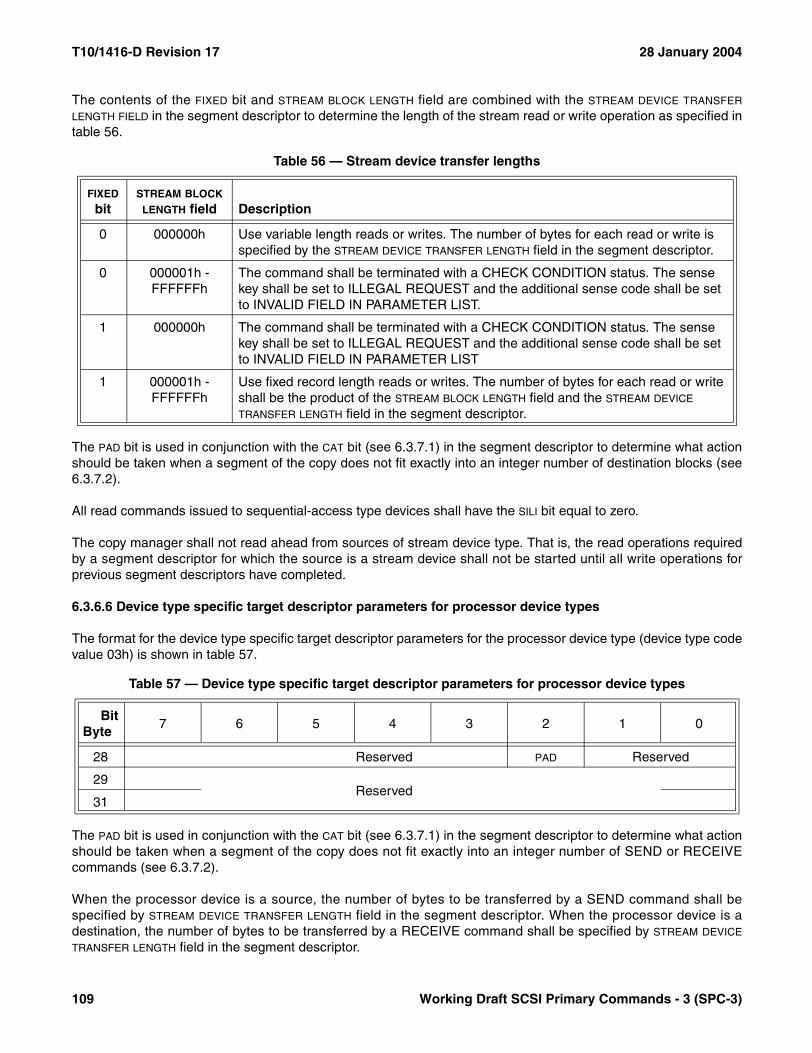
T10/1416-D Revision 17 28 January 2004
The contents of the FIXED bit and STREAM BLOCK LENGTH field are combined with the STREAM DEVICE TRANSFER
LENGTH FIELD in the segment descriptor to determine the length of the stream read or write operation as specified intable 56.
The PAD bit is used in conjunction with the CAT bit (see 6.3.7.1) in the segment descriptor to determine what actionshould be taken when a segment of the copy does not fit exactly into an integer number of destination blocks (see6.3.7.2).
All read commands issued to sequential-access type devices shall have the SILI bit equal to zero.
The copy manager shall not read ahead from sources of stream device type. That is, the read operations requiredby a segment descriptor for which the source is a stream device shall not be started until all write operations forprevious segment descriptors have completed.
6.3.6.6 Device type specific target descriptor parameters for processor device types
The format for the device type specific target descriptor parameters for the processor device type (device type codevalue 03h) is shown in table 57.
The PAD bit is used in conjunction with the CAT bit (see 6.3.7.1) in the segment descriptor to determine what actionshould be taken when a segment of the copy does not fit exactly into an integer number of SEND or RECEIVEcommands (see 6.3.7.2).
When the processor device is a source, the number of bytes to be transferred by a SEND command shall bespecified by STREAM DEVICE TRANSFER LENGTH field in the segment descriptor. When the processor device is adestination, the number of bytes to be transferred by a RECEIVE command shall be specified by STREAM DEVICE
TRANSFER LENGTH field in the segment descriptor.
Table 56 — Stream device transfer lengths
FIXED bit
STREAM BLOCK
LENGTH field Description
0 000000h Use variable length reads or writes. The number of bytes for each read or write is specified by the STREAM DEVICE TRANSFER LENGTH field in the segment descriptor.
0 000001h - FFFFFFh
The command shall be terminated with a CHECK CONDITION status. The sense key shall be set to ILLEGAL REQUEST and the additional sense code shall be set to INVALID FIELD IN PARAMETER LIST.
1 000000h The command shall be terminated with a CHECK CONDITION status. The sense key shall be set to ILLEGAL REQUEST and the additional sense code shall be set to INVALID FIELD IN PARAMETER LIST
1 000001h - FFFFFFh
Use fixed record length reads or writes. The number of bytes for each read or write shall be the product of the STREAM BLOCK LENGTH field and the STREAM DEVICE TRANSFER LENGTH field in the segment descriptor.
Table 57 — Device type specific target descriptor parameters for processor device types
BitByte
7 6 5 4 3 2 1 0
28 Reserved PAD Reserved
29Reserved
31
109 Working Draft SCSI Primary Commands - 3 (SPC-3)

28 January 2004 T10/1416-D Revision 17
6.3.7 Segment descriptors
6.3.7.1 Segment descriptors introduction
Segment descriptors (see table 58) begin with an eight byte header.
The DESCRIPTOR TYPE CODE field is described in 6.3.5. Support for each segment descriptor format is optional. If acopy manager receives an unsupported descriptor type code in a segment descriptor, the command shall be termi-nated with CHECK CONDITION status. The sense key shall be set to ILLEGAL REQUEST and the additionalsense code shall be set to UNSUPPORTED SEGMENT DESCRIPTOR TYPE CODE.
The destination count (DC) bit is only applicable to segment descriptors with descriptor type code values of 02h and0Dh (see 6.3.7.5). The DC bit is reserved for all other segment descriptors.
The CAT bit is described in 6.3.7.2.
The DESCRIPTOR LENGTH field contains the length in bytes of the fields that follow the DESCRIPTOR LENGTH field in thesegment descriptor. In most cases, the length is constant.
The SOURCE TARGET DESCRIPTOR INDEX field contains an index into the target descriptor list (see 6.3.1) identifyingthe source copy target device. The DESTINATION TARGET DESCRIPTOR INDEX field contains an index into the targetdescriptor list (see 6.3.1) identifying the destination copy target device. Some segment descriptor formats do notrequire a SOURCE TARGET DESCRIPTOR INDEX field or a DESTINATION TARGET DESCRIPTOR INDEX field, in which casethe field is reserved.
If the target identified by a SOURCE TARGET DESCRIPTOR INDEX field or a DESTINATION TARGET DESCRIPTOR INDEX fieldis not accessible to the copy manager, then the command shall be terminated with a CHECK CONDITION status,the sense key shall be set to COPY ABORTED and the additional sense code shall be set to UNREACHABLECOPY TARGET.
Table 58 — Segment descriptor header
BitByte
7 6 5 4 3 2 1 0
0 DESCRIPTOR TYPE CODE (00h-3Fh)
1 Reserved DC CAT
2 (MSB)DESCRIPTOR LENGTH (n-7)
3 (LSB)
4 (MSB)SOURCE TARGET DESCRIPTOR INDEX
5 (LSB)
6 (MSB)DESTINATION TARGET DESCRIPTOR INDEX
7 (LSB)
8Segment descriptor parameters
n
Working Draft SCSI Primary Commands - 3 (SPC-3) 110

T10/1416-D Revision 17 28 January 2004
6.3.7.2 Segment descriptor processing
In processing a segment descriptor, the copy manager may be required to:
a) Read source data by issuing data input commands to the source device;b) Process data, an operation that generally designates data as destination data intended for transfer to the
destination device; and c) Write some or all of the destination data to the destination device.
The number of blocks to read and write, the number of bytes to process, and the nature of processing are deter-mined by the segment descriptor type code, the parameters of the segment descriptor, and the amount of residualsource or destination data retained from the previous segment, if any.
Except as otherwise specified by particular segment descriptor type codes:
a) Just enough whole-block read operations shall be performed to supply, together with residual source datafrom the previous segment or segments, the number of bytes to be processed;
b) Processing consists of removing bytes from the source data and designating them as destination data,without change; and
c) As many whole-block write operations as possible shall be performed with the destination data, includingany residual destination data from the previous segment or segments.
Any residual source data from the previous segment or segments shall be processed before any data read from thesource device during processing of the current segment descriptor. Any residual destination data from the previoussegment or segments shall be written before any data processed during processing of the current segmentdescriptor.
Exceptions and clarifications to these general rules are described in table 59 and the subclauses it references.
Table 59 — Descriptor Type Code Dependent Copy Manager Processing (part 1 of 2)
Segment Descriptor Type Code Reference Description
00h (block→ stream) or0Bh (block→ stream+application client)
6.3.7.3 The number of bytes processed is determined by the BLOCK DEVICE NUMBER OF BLOCKS field for the source blocks (see applicable type code definition subclauses
for details). a02h (block→ block) or0Dh (block→ block+application client)with DC=0
6.3.7.5
02h (block→ block) or0Dh (block→ block+application client)with DC=1
6.3.7.5 The number of blocks or byte range specified shall be output to the destination device. If residual destination data is sufficient to perform the output then no data shall be processed. Otherwise, just as much data as needed shall be processed (which may involve reading data from the source device) so that the destination data (which includes any residual destination data from
the previous segment) is sufficient. a
01h (stream→ block) or0Ch (stream→ block+application client)
6.3.7.3
09h (stream→ block<o>)6.3.7.12
03h (stream→ stream) or0Eh (stream→ stream+application client)
6.3.7.6 The number of bytes specified in the segment
descriptor shall be processed. a
a For segment descriptor type codes 0Bh, 0Ch, 0Dh and 0Eh, a copy of the processed data shall also be held for retrieval by the application client.
111 Working Draft SCSI Primary Commands - 3 (SPC-3)
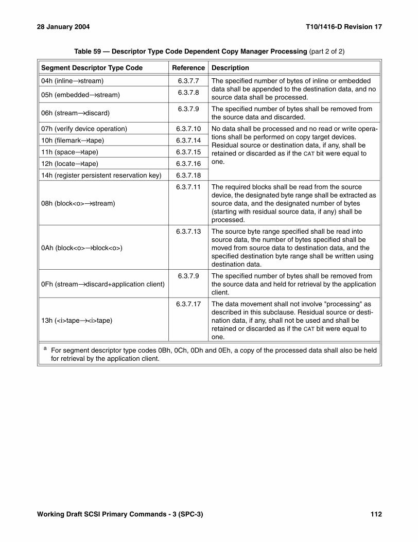
28 January 2004 T10/1416-D Revision 17
04h (inline→ stream) 6.3.7.7 The specified number of bytes of inline or embedded data shall be appended to the destination data, and no source data shall be processed.05h (embedded→ stream) 6.3.7.8
06h (stream→ discard)6.3.7.9 The specified number of bytes shall be removed from
the source data and discarded.
07h (verify device operation) 6.3.7.10 No data shall be processed and no read or write opera-tions shall be performed on copy target devices. Residual source or destination data, if any, shall be retained or discarded as if the CAT bit were equal to one.
10h (filemark→ tape) 6.3.7.14
11h (space→ tape) 6.3.7.15
12h (locate→ tape) 6.3.7.16
14h (register persistent reservation key) 6.3.7.18
08h (block<o>→ stream)
6.3.7.11 The required blocks shall be read from the source device, the designated byte range shall be extracted as source data, and the designated number of bytes (starting with residual source data, if any) shall be processed.
0Ah (block<o>→ block<o>)
6.3.7.13 The source byte range specified shall be read into source data, the number of bytes specified shall be moved from source data to destination data, and the specified destination byte range shall be written using destination data.
0Fh (stream→ discard+application client)6.3.7.9 The specified number of bytes shall be removed from
the source data and held for retrieval by the application client.
13h (<i>tape→ <i>tape)
6.3.7.17 The data movement shall not involve "processing" as described in this subclause. Residual source or desti-nation data, if any, shall not be used and shall be retained or discarded as if the CAT bit were equal to one.
Table 59 — Descriptor Type Code Dependent Copy Manager Processing (part 2 of 2)
Segment Descriptor Type Code Reference Description
a For segment descriptor type codes 0Bh, 0Ch, 0Dh and 0Eh, a copy of the processed data shall also be held for retrieval by the application client.
Working Draft SCSI Primary Commands - 3 (SPC-3) 112

T10/1416-D Revision 17 28 January 2004
Reads and writes shall be performed using whole-block transfer lengths determined by the block size, transferlength, or both. Therefore some source data may remain unprocessed and some destination data may not havebeen transferred at the end of a segment. If so, the residue shall be handled according to the CAT bit in the segmentdescriptor and the PAD bits of the source and destination target descriptors, as defined in table 60.
A few segment descriptors have either no source or no target and handling of the PAD bit for those descriptors shallbe as follows. For segment descriptor types 04h (inline→ stream, see 6.3.7.7) and 05h (embedded→ stream, see6.3.7.8), the handling shall be as if the PAD were equal to zero for the source target descriptor. For segmentdescriptor types 06h and 0Fh (stream→ discard and stream→ discard+application client, see 6.3.7.9), handlingshall be as if the PAD were equal to zero for the destination target descriptor.
Table 60 — PAD and CAT bit definitions
PAD bit in
CAT bit Copy manager action
Source target
descriptor
Destination target
descriptor
0 or 1 0 or 1 1 Any residual source data shall be retained as source data for a subse-quent segment descriptor. Any residual destination data shall be retained as destination data for a subsequent segment descriptor. It shall not be an error if either the source or destination target index in the following segment descriptor does not match the corresponding target index with which residual data was originally associated. If the CAT bit is set to one on the last segment of an EXTENDED COPY command any residual data shall be discarded; this shall not be considered an error.
1 1 0 Any residual source data shall be discarded. Any residual destination
data shall be padded with zeroes to make a whole block transfer. a
0 1 0 Any residual source data shall be handled as if the CAT bit is equal to one (i.e., discarded on the last segment and retained otherwise). Any residual destination data shall be padded with zeroes to make a whole
block transfer. a
1 0 0 Any residual source or destination data shall be discarded.
0 0 0 If there is residual source or destination data the EXTENDED COPY command shall be terminated with a CHECK CONDITION status. The sense key shall be set to an COPY ABORTED and the additional sense code shall be set to UNEXPECTED INEXACT SEGMENT.
a When the CAT bit is set to zero and the destination target descriptor has the PAD bit set to one, the EXTENDED COPY command shall be terminated with a CHECK CONDITION status, the sense key shall be set to COPY ABORTED, and the additional sense code shall be set to UNEXPECTED INEXACT SEGMENT if any of the following conditions are met:a) If any residual destination data is present after writing the designated byte range for a segment
descriptor of type 09h (stream→ block <o>) or 0Ah (block<o>→ block<o>); or b) If any residual destination data is present after the designated number of blocks have been written for a
segment descriptor of type 02h (block→ block) with DC set to one, 0Dh (block→ block+application client) with DC set to one, 01h (stream→ block) or 0Ch (stream→ block+application client).
113 Working Draft SCSI Primary Commands - 3 (SPC-3)

28 January 2004 T10/1416-D Revision 17
6.3.7.3 Block device to stream device operations
The segment descriptor format shown in table 61 is used by the copy operations that move data from a blockdevice to a stream device or vice versa.
The DESCRIPTOR TYPE CODE field is described in 6.3.5 and 6.3.7.1. Two DESCRIPTOR TYPE CODE values use thesegment descriptor format shown in table 61 and described in this subclause.
For descriptor type code 00h (block→stream) or descriptor type code 0Bh (block→stream+application client), thecopy manager shall copy the data from the source block device identified by the SOURCE TARGET DESCRIPTOR INDEX
field to the destination stream device identified by the DESTINATION TARGET DESCRIPTOR INDEX field using the logicalblocks starting at the location identified by the BLOCK DEVICE LOGICAL BLOCK ADDRESS field. As many blocks shall beread as necessary to process (see 6.3.7.2) a number of bytes equal to the contents of the DISK BLOCK LENGTH fieldin the target descriptor for the source device times the contents of the BLOCK DEVICE NUMBER OF BLOCKS field. Thedata shall be written to the stream device starting at the current position of the media.
For descriptor type code 0Bh (block→stream+application client), the copy manager also shall hold a copy of theprocessed data for delivery to the application client upon completion of the EXTENDED COPY command inresponse to a RECEIVE COPY RESULTS command with RECEIVE DATA service action as described in 6.17.3.The minimum amount of held data supported by the copy manager is returned in the response data for theRECEIVE COPY RESULTS command with OPERATING PARAMETERS service action (see 6.17.4). If the copymanager supports the 0Bh descriptor type code it also shall support the RECEIVE COPY RESULTS commandwith RECEIVE DATA service action.
Table 61 — Block device to or from stream device segment descriptor
BitByte
7 6 5 4 3 2 1 0
0 DESCRIPTOR TYPE CODE (00h, 01h, 0Bh, or 0Ch)
1 Reserved CAT
2 (MSB)DESCRIPTOR LENGTH (0014h)
3 (LSB)
4 (MSB)SOURCE TARGET DESCRIPTOR INDEX
5 (LSB)
6 (MSB)DESTINATION TARGET DESCRIPTOR INDEX
7 (LSB)
8 Reserved
9 (MSB)
STREAM DEVICE TRANSFER LENGTH10
11 (LSB)
12 Reserved
13 Reserved
14 (MSB)BLOCK DEVICE NUMBER OF BLOCKS
15 (LSB)
16 (MSB)BLOCK DEVICE LOGICAL BLOCK ADDRESS
23 (LSB)
Working Draft SCSI Primary Commands - 3 (SPC-3) 114
T10/1416-D Revision 17 28 January 2004
The CAT bit is described in 6.3.7.2.
The DESCRIPTOR LENGTH field shall contain 20 (0014h). The SOURCE TARGET DESCRIPTOR INDEX and DESTINATION
TARGET DESCRIPTOR INDEX fields are described in 6.3.7.1.
The STREAM DEVICE TRANSFER LENGTH field specifies the amount of data to be written on each write operation to thestream device. See 6.3.6.5 for a description of how data in the STREAM DEVICE TRANSFER LENGTH field in thesegment descriptor interacts with data in the STREAM BLOCK LENGTH field in the device type specific targetdescriptor parameters for the sequential-access device type.
The BLOCK DEVICE NUMBER OF BLOCKS field specifies the length, in source logical blocks, of data to be processed(see 6.3.7.2) in the segment. A value of zero shall not be considered as an error. No data shall be processed, butany residual destination data retained from a previous segment shall be written if possible to the destination inwhole-block transfers. A value of zero shall not modify the handling of residual data.
The BLOCK DEVICE LOGICAL BLOCK ADDRESS field specifies the starting logical block address on the block device forthis segment.
6.3.7.4 Stream device to block device operations
The segment descriptor format shown in table 61 (see 6.3.7.3) also is used by the copy operations that move datafrom a stream device to a block device. Two DESCRIPTOR TYPE CODE values use the segment descriptor formatshown in table 61 and described in this subclause.
For descriptor type code 01h (stream→block) or descriptor type code 0Ch (stream→block+application client), thecopy manager shall copy the data from the source stream device identified by the SOURCE TARGET DESCRIPTOR
INDEX field to the destination block device identified by the DESTINATION TARGET DESCRIPTOR INDEX field using thestream data starting at the current position of the stream device. The data shall be written to logical blocks startingat the location identified by the BLOCK DEVICE LOGICAL BLOCK ADDRESS field and continuing for the number of blocksspecified in the BLOCK DEVICE NUMBER OF BLOCKS field.
For descriptor type code 0Ch (stream→block+application client), the copy manager also shall hold a copy of theprocessed data for delivery to the application client upon completion of the EXTENDED COPY command inresponse to a RECEIVE COPY RESULTS command with RECEIVE DATA service action as described in 6.17.3.The minimum amount of held data supported by the copy manager is returned in the response data for theRECEIVE COPY RESULTS command with OPERATING PARAMETERS service action (see 6.17.4). If the copymanager supports the 0Ch descriptor type code it also shall support the RECEIVE COPY RESULTS commandwith RECEIVE DATA service action.
The CAT bit is described in 6.3.7.2.
The DESCRIPTOR LENGTH field shall contain 20 (0014h). The SOURCE TARGET DESCRIPTOR INDEX and DESTINATION
TARGET DESCRIPTOR INDEX fields are described in 6.3.7.1.
The STREAM DEVICE TRANSFER LENGTH field specifies the amount of data to be read from the source stream deviceon each read operation. See 6.3.6.5 for a description of how data in the STREAM DEVICE TRANSFER LENGTH field inthe segment descriptor interacts with data in the STREAM BLOCK LENGTH field in the device type specific targetdescriptor parameters for the sequential-access device type.
The BLOCK DEVICE NUMBER OF BLOCKS field specifies the number blocks to be written by the segment. A value ofzero indicates that no blocks shall be written in this segment. This shall not be considered as an error.
The BLOCK DEVICE LOGICAL BLOCK ADDRESS field specifies the starting logical block address on the block device forthis segment.
115 Working Draft SCSI Primary Commands - 3 (SPC-3)

28 January 2004 T10/1416-D Revision 17
6.3.7.5 Block device to block device operations
The segment descriptor format shown in table 62 is used by the copy operations that move data from a blockdevice to a block device.
The DESCRIPTOR TYPE CODE field is described in 6.3.5 and 6.3.7.1. Two DESCRIPTOR TYPE CODE values use thesegment descriptor format shown in table 62 and described in this subclause.
For descriptor type code 02h (block→block) or descriptor type code 0Dh (block→block+application client), the copymanager shall copy the data from the source block device identified by the SOURCE TARGET DESCRIPTOR INDEX fieldto the destination block device identified by the DESTINATION TARGET DESCRIPTOR INDEX field using the logical blocksstarting at the location identified by the SOURCE BLOCK DEVICE LOGICAL BLOCK ADDRESS field. The data shall bewritten to logical blocks starting at the location identified by the DESTINATION BLOCK DEVICE LOGICAL BLOCK ADDRESS
field.
If the DC bit equals zero, as many blocks shall be read as necessary to process (see 6.3.7.2) a number of bytesequal to the contents of the DISK BLOCK LENGTH field in the target descriptor for the source device times the contentsof the BLOCK DEVICE NUMBER OF BLOCKS field, and as many writes as possible shall be performed using any residualdestination data from the previous segment and the data processed in this segment. If the DC bit equals one, thenumber of blocks specified by the BLOCK DEVICE NUMBER OF BLOCKS field shall be written to the destination blockdevice, as many bytes shall be processed as necessary for these writes to be performed, and as many blocks shallbe read as necessary to supply the data to be processed.
For descriptor type code 0Dh (block→block+application client), the copy manager also shall hold a copy of theprocessed data for delivery to the application client upon completion of the EXTENDED COPY command inresponse to a RECEIVE COPY RESULTS command with RECEIVE DATA service action as described in 6.17.3.
Table 62 — Block device to block device segment descriptor
BitByte
7 6 5 4 3 2 1 0
0 DESCRIPTOR TYPE CODE (02h or 0Dh)
1 Reserved DC CAT
2 (MSB)DESCRIPTOR LENGTH (0018h)
3 (LSB)
4 (MSB)SOURCE TARGET DESCRIPTOR INDEX
5 (LSB)
6 (MSB)DESTINATION TARGET DESCRIPTOR INDEX
7 (LSB)
8 Reserved
9 Reserved
10 (MSB)BLOCK DEVICE NUMBER OF BLOCKS
11 (LSB)
12 (MSB)SOURCE BLOCK DEVICE LOGICAL BLOCK ADDRESS
19 (LSB)
20 (MSB)DESTINATION BLOCK DEVICE LOGICAL BLOCK ADDRESS
27 (LSB)
Working Draft SCSI Primary Commands - 3 (SPC-3) 116

T10/1416-D Revision 17 28 January 2004
The minimum amount of held data supported by the copy manager is returned in the response data for theRECEIVE COPY RESULTS command with OPERATING PARAMETERS service action (see 6.17.4). If the copymanager supports the 0Dh descriptor type code it also shall support the RECEIVE COPY RESULTS commandwith RECEIVE DATA service action.
The CAT bit is described in 6.3.7.2.
The destination count (DC) bit indicates whether the BLOCK DEVICE NUMBER OF BLOCKS field refers to the source ordestination device. A DC bit set to zero indicates that the BLOCK DEVICE NUMBER OF BLOCKS field refers to the sourcedevice. A DC bit set to one indicates that the BLOCK DEVICE NUMBER OF BLOCKS field refers to the destination device.
The DESCRIPTOR LENGTH field shall contain 24 (0018h). The SOURCE TARGET DESCRIPTOR INDEX and DESTINATION
TARGET DESCRIPTOR INDEX fields are described in 6.3.7.1.
The BLOCK DEVICE NUMBER OF BLOCKS field specifies the number of blocks to be processed (if DC is set to zero) or tobe written to the destination device (if DC is set to one). A value of zero shall not be considered as an error. If the DC
bit equals one, a value of zero indicates that no destination blocks shall be written and the only processing to beperformed is that any residual source or destination data from the previous segment shall be handled as residualdata as described in 6.3.7.2. If the DC bit equals zero, a value of zero indicates that no source blocks shall be readand no source data shall be processed, but any residual destination data from a previous segment shall be writtenif possible to the destination in whole-block transfers, and any residual data shall be handled as described in6.3.7.2.
The SOURCE BLOCK DEVICE LOGICAL BLOCK ADDRESS field specifies the logical block address from which the readingof data shall start.
The DESTINATION BLOCK DEVICE LOGICAL BLOCK ADDRESS field specifies the logical block address to which the writingof data shall begin.
117 Working Draft SCSI Primary Commands - 3 (SPC-3)
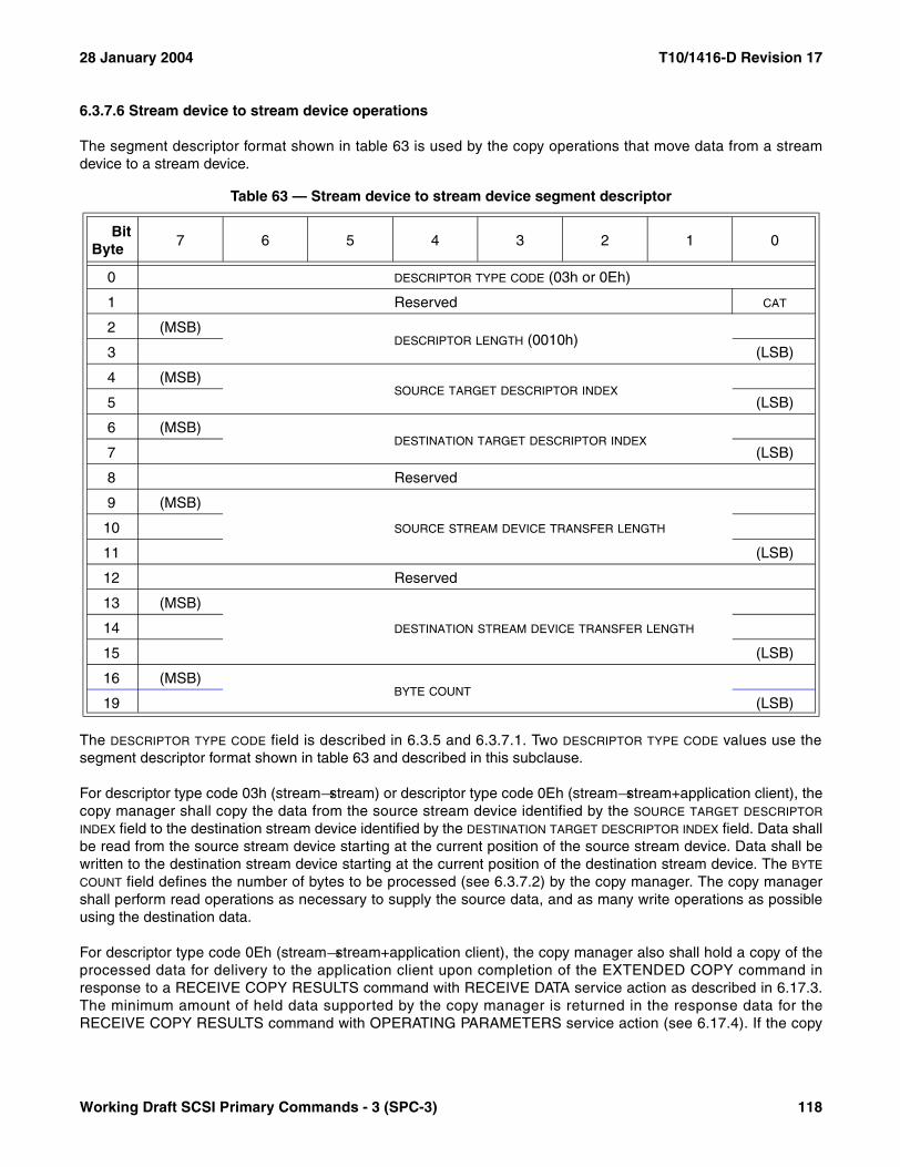
28 January 2004 T10/1416-D Revision 17
6.3.7.6 Stream device to stream device operations
The segment descriptor format shown in table 63 is used by the copy operations that move data from a streamdevice to a stream device.
The DESCRIPTOR TYPE CODE field is described in 6.3.5 and 6.3.7.1. Two DESCRIPTOR TYPE CODE values use thesegment descriptor format shown in table 63 and described in this subclause.
For descriptor type code 03h (stream→stream) or descriptor type code 0Eh (stream→stream+application client), thecopy manager shall copy the data from the source stream device identified by the SOURCE TARGET DESCRIPTOR
INDEX field to the destination stream device identified by the DESTINATION TARGET DESCRIPTOR INDEX field. Data shallbe read from the source stream device starting at the current position of the source stream device. Data shall bewritten to the destination stream device starting at the current position of the destination stream device. The BYTE
COUNT field defines the number of bytes to be processed (see 6.3.7.2) by the copy manager. The copy managershall perform read operations as necessary to supply the source data, and as many write operations as possibleusing the destination data.
For descriptor type code 0Eh (stream→stream+application client), the copy manager also shall hold a copy of theprocessed data for delivery to the application client upon completion of the EXTENDED COPY command inresponse to a RECEIVE COPY RESULTS command with RECEIVE DATA service action as described in 6.17.3.The minimum amount of held data supported by the copy manager is returned in the response data for theRECEIVE COPY RESULTS command with OPERATING PARAMETERS service action (see 6.17.4). If the copy
Table 63 — Stream device to stream device segment descriptor
BitByte
7 6 5 4 3 2 1 0
0 DESCRIPTOR TYPE CODE (03h or 0Eh)
1 Reserved CAT
2 (MSB)DESCRIPTOR LENGTH (0010h)
3 (LSB)
4 (MSB)SOURCE TARGET DESCRIPTOR INDEX
5 (LSB)
6 (MSB)DESTINATION TARGET DESCRIPTOR INDEX
7 (LSB)
8 Reserved
9 (MSB)
SOURCE STREAM DEVICE TRANSFER LENGTH10
11 (LSB)
12 Reserved
13 (MSB)
DESTINATION STREAM DEVICE TRANSFER LENGTH14
15 (LSB)
16 (MSB)BYTE COUNT
19 (LSB)
Working Draft SCSI Primary Commands - 3 (SPC-3) 118
T10/1416-D Revision 17 28 January 2004
manager supports the 0Eh descriptor type code it also shall support the RECEIVE COPY RESULTS commandwith RECEIVE DATA service action.
The CAT bit is described in 6.3.7.2.
The DESCRIPTOR LENGTH field shall contain 16 (0010h). The SOURCE TARGET DESCRIPTOR INDEX and DESTINATION
TARGET DESCRIPTOR INDEX fields are described in 6.3.7.1.
The SOURCE STREAM DEVICE TRANSFER LENGTH field specifies the amount of data to be read from the source streamdevice on each read operation. See 6.3.6.5 for a description of how data in the SOURCE STREAM DEVICE TRANSFER
LENGTH field in the segment descriptor interacts with data in the STREAM BLOCK LENGTH field in the device typespecific target descriptor parameters for the source sequential-access device type.
The DESTINATION STREAM DEVICE TRANSFER LENGTH field specifies the amount of data to be written to the destinationstream device on each write operation. See 6.3.6.5 for a description of how data in the DESTINATION STREAM DEVICE
TRANSFER LENGTH field in the segment descriptor interacts with data in the STREAM BLOCK LENGTH field in the devicetype specific target descriptor parameters for the destination sequential-access device type.
The BYTE COUNT field specifies the number of bytes that shall be processed for this segment descriptor. A value ofzero shall not be considered as an error, and shall specify that no source blocks shall be read and no source datashall be processed. However, a value of zero shall specify that any residual destination data from a previoussegment shall be written if possible to the destination in whole-block transfers, and any residual data shall behandled as described in 6.3.7.2.
119 Working Draft SCSI Primary Commands - 3 (SPC-3)
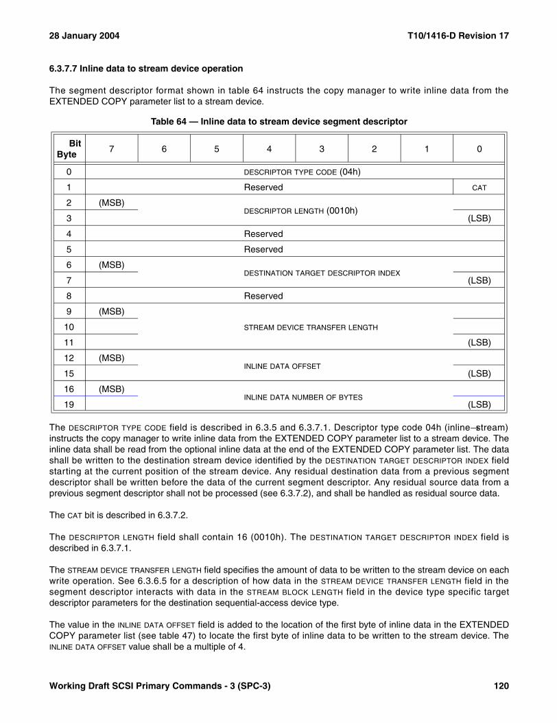
28 January 2004 T10/1416-D Revision 17
6.3.7.7 Inline data to stream device operation
The segment descriptor format shown in table 64 instructs the copy manager to write inline data from theEXTENDED COPY parameter list to a stream device.
The DESCRIPTOR TYPE CODE field is described in 6.3.5 and 6.3.7.1. Descriptor type code 04h (inline→stream)instructs the copy manager to write inline data from the EXTENDED COPY parameter list to a stream device. Theinline data shall be read from the optional inline data at the end of the EXTENDED COPY parameter list. The datashall be written to the destination stream device identified by the DESTINATION TARGET DESCRIPTOR INDEX fieldstarting at the current position of the stream device. Any residual destination data from a previous segmentdescriptor shall be written before the data of the current segment descriptor. Any residual source data from aprevious segment descriptor shall not be processed (see 6.3.7.2), and shall be handled as residual source data.
The CAT bit is described in 6.3.7.2.
The DESCRIPTOR LENGTH field shall contain 16 (0010h). The DESTINATION TARGET DESCRIPTOR INDEX field isdescribed in 6.3.7.1.
The STREAM DEVICE TRANSFER LENGTH field specifies the amount of data to be written to the stream device on eachwrite operation. See 6.3.6.5 for a description of how data in the STREAM DEVICE TRANSFER LENGTH field in thesegment descriptor interacts with data in the STREAM BLOCK LENGTH field in the device type specific targetdescriptor parameters for the destination sequential-access device type.
The value in the INLINE DATA OFFSET field is added to the location of the first byte of inline data in the EXTENDEDCOPY parameter list (see table 47) to locate the first byte of inline data to be written to the stream device. TheINLINE DATA OFFSET value shall be a multiple of 4.
Table 64 — Inline data to stream device segment descriptor
BitByte
7 6 5 4 3 2 1 0
0 DESCRIPTOR TYPE CODE (04h)
1 Reserved CAT
2 (MSB)DESCRIPTOR LENGTH (0010h)
3 (LSB)
4 Reserved
5 Reserved
6 (MSB)DESTINATION TARGET DESCRIPTOR INDEX
7 (LSB)
8 Reserved
9 (MSB)
STREAM DEVICE TRANSFER LENGTH10
11 (LSB)
12 (MSB)INLINE DATA OFFSET
15 (LSB)
16 (MSB)INLINE DATA NUMBER OF BYTES
19 (LSB)
Working Draft SCSI Primary Commands - 3 (SPC-3) 120

T10/1416-D Revision 17 28 January 2004
The INLINE DATA NUMBER OF BYTES field specifies the number of bytes of inline data that are to be transferred to thestream device. A value of zero shall not be considered an error.
If the sum of the INLINE DATA OFFSET and the INLINE DATA NUMBER OF BYTES values exceeds the value in the INLINE
DATA LENGTH field (see table 47), the copy manager shall terminate the command with a CHECK CONDITIONstatus. The sense key shall be set to COPY ABORTED and the additional sense code shall be set to INLINE DATALENGTH EXCEEDED.
6.3.7.8 Embedded data to stream device operation
The segment descriptor format shown in table 65 instructs the copy manager to write embedded data from thesegment descriptor to a stream device.
The DESCRIPTOR TYPE CODE field is described in 6.3.5 and 6.3.7.1. Descriptor type code 05h (embedded→stream)instructs the copy manager to write embedded data from the segment descriptor to a stream device. Theembedded data shall be read from the segment descriptor. The data shall be written to the destination streamdevice identified by the DESTINATION TARGET DESCRIPTOR INDEX field starting at the current position of the streamdevice. Any residual destination data from a previous segment descriptor shall be written before the data of thecurrent segment descriptor. Any residual source data from a previous segment descriptor shall not be processed(see 6.3.7.2), and shall be handled as residual source data.
The CAT bit is described in 6.3.7.2.
Table 65 — Embedded data to stream device segment descriptor
BitByte
7 6 5 4 3 2 1 0
0 DESCRIPTOR TYPE CODE (05h)
1 Reserved CAT
2 (MSB)DESCRIPTOR LENGTH (n-3)
3 (LSB)
4 Reserved
5 Reserved
6 (MSB)DESTINATION TARGET DESCRIPTOR INDEX
7 (LSB)
8 Reserved
9 (MSB)
STREAM DEVICE TRANSFER LENGTH10
11 (LSB)
12 (MSB)EMBEDDED DATA NUMBER OF BYTES
13 (LSB)
14Reserved
15
16EMBEDDED DATA
n
121 Working Draft SCSI Primary Commands - 3 (SPC-3)
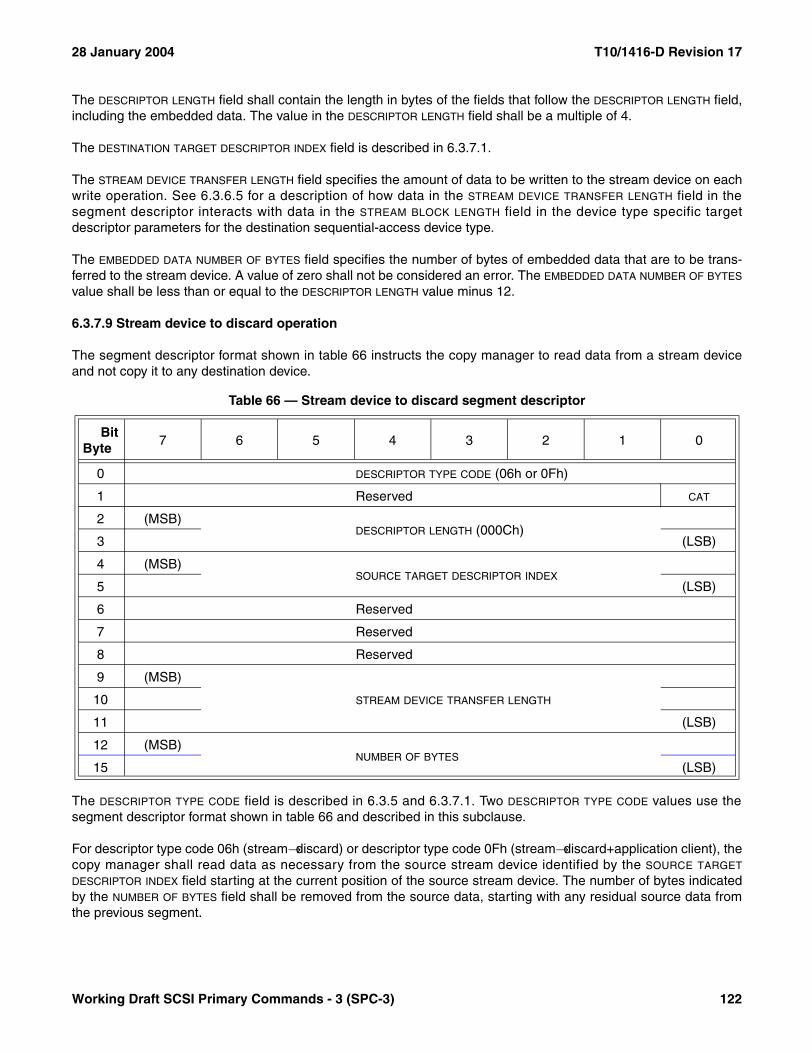
28 January 2004 T10/1416-D Revision 17
The DESCRIPTOR LENGTH field shall contain the length in bytes of the fields that follow the DESCRIPTOR LENGTH field,including the embedded data. The value in the DESCRIPTOR LENGTH field shall be a multiple of 4.
The DESTINATION TARGET DESCRIPTOR INDEX field is described in 6.3.7.1.
The STREAM DEVICE TRANSFER LENGTH field specifies the amount of data to be written to the stream device on eachwrite operation. See 6.3.6.5 for a description of how data in the STREAM DEVICE TRANSFER LENGTH field in thesegment descriptor interacts with data in the STREAM BLOCK LENGTH field in the device type specific targetdescriptor parameters for the destination sequential-access device type.
The EMBEDDED DATA NUMBER OF BYTES field specifies the number of bytes of embedded data that are to be trans-ferred to the stream device. A value of zero shall not be considered an error. The EMBEDDED DATA NUMBER OF BYTES
value shall be less than or equal to the DESCRIPTOR LENGTH value minus 12.
6.3.7.9 Stream device to discard operation
The segment descriptor format shown in table 66 instructs the copy manager to read data from a stream deviceand not copy it to any destination device.
The DESCRIPTOR TYPE CODE field is described in 6.3.5 and 6.3.7.1. Two DESCRIPTOR TYPE CODE values use thesegment descriptor format shown in table 66 and described in this subclause.
For descriptor type code 06h (stream→discard) or descriptor type code 0Fh (stream→discard+application client), thecopy manager shall read data as necessary from the source stream device identified by the SOURCE TARGET
DESCRIPTOR INDEX field starting at the current position of the source stream device. The number of bytes indicatedby the NUMBER OF BYTES field shall be removed from the source data, starting with any residual source data fromthe previous segment.
Table 66 — Stream device to discard segment descriptor
BitByte
7 6 5 4 3 2 1 0
0 DESCRIPTOR TYPE CODE (06h or 0Fh)
1 Reserved CAT
2 (MSB)DESCRIPTOR LENGTH (000Ch)
3 (LSB)
4 (MSB)SOURCE TARGET DESCRIPTOR INDEX
5 (LSB)
6 Reserved
7 Reserved
8 Reserved
9 (MSB)
STREAM DEVICE TRANSFER LENGTH10
11 (LSB)
12 (MSB)NUMBER OF BYTES
15 (LSB)
Working Draft SCSI Primary Commands - 3 (SPC-3) 122

T10/1416-D Revision 17 28 January 2004
For descriptor type code 06h (stream→discard) the removed data shall be discarded and not written to any desti-nation device. For descriptor type code 0Fh (stream→discard+application client) the removed data shall be held fordelivery to the application client upon completion of the EXTENDED COPY command in response to a RECEIVECOPY RESULTS command with RECEIVE DATA service action as described in 6.17.3. The minimum amount ofheld data supported by the copy manager is returned in the response data for the RECEIVE COPY RESULTScommand with OPERATING PARAMETERS service action (see 6.17.4). If the copy manager supports the 0Fh(stream→discard+application client) descriptor type code it also shall support the RECEIVE COPY RESULTScommand with RECEIVE DATA service action.
The CAT bit is described in 6.3.7.2.
The DESCRIPTOR LENGTH field shall contain 12 (000Ch). The DESTINATION TARGET DESCRIPTOR INDEX field isdescribed in 6.3.7.1.
The SOURCE STREAM DEVICE TRANSFER LENGTH field specifies the amount of data to be read from the source streamdevice on each read operation. See 6.3.6.5 for a description of how data in the SOURCE STREAM DEVICE TRANSFER
LENGTH field in the segment descriptor interacts with data in the STREAM BLOCK LENGTH field in the device typespecific target descriptor parameters for the source sequential-access device type.
The NUMBER OF BYTES field specifies the number of bytes to be removed from the source data.
6.3.7.10 Verify device operation
The segment descriptor format shown in table 67 instructs the copy manager to verify the accessibility of a SCSIdevice.
The DESCRIPTOR TYPE CODE field is described in 6.3.5 and 6.3.7.1. Descriptor type code 07h instructs the copymanager to verify the accessibility of the device identified by the SOURCE TARGET DESCRIPTOR INDEX field.
The DESCRIPTOR LENGTH field shall contain 8 (0008h). The SOURCE TARGET DESCRIPTOR INDEX field is described in6.3.7.1.
Table 67 — Verify device operation segment descriptor
BitByte
7 6 5 4 3 2 1 0
0 DESCRIPTOR TYPE CODE (07h)
1 Reserved
2 (MSB)DESCRIPTOR LENGTH (0008h)
3 (LSB)
4 (MSB)SOURCE TARGET DESCRIPTOR INDEX
5 (LSB)
6Reserved
7
8 Reserved TUR
9Reserved
11
123 Working Draft SCSI Primary Commands - 3 (SPC-3)
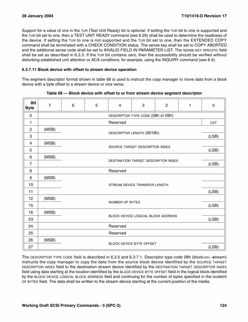
28 January 2004 T10/1416-D Revision 17
Support for a value of one in the TUR (Test Unit Ready) bit is optional. If setting the TUR bit to one is supported andthe TUR bit set to one, then a TEST UNIT READY command (see 6.29) shall be used to determine the readiness ofthe device. If setting the TUR to one is not supported and the TUR bit set to one, then the EXTENDED COPYcommand shall be terminated with a CHECK CONDITION status. The sense key shall be set to COPY ABORTEDand the additional sense code shall be set to INVALID FIELD IN PARAMETER LIST. The SENSE-KEY SPECIFIC fieldshall be set as described in 6.3.3. If the TUR bit contains zero, then the accessibility should be verified withoutdisturbing established unit attention or ACA conditions, for example, using the INQUIRY command (see 6.4).
6.3.7.11 Block device with offset to stream device operation
The segment descriptor format shown in table 68 is used to instruct the copy manager to move data from a blockdevice with a byte offset to a stream device or vice versa.
The DESCRIPTOR TYPE CODE field is described in 6.3.5 and 6.3.7.1. Descriptor type code 08h (block<o>→stream)instructs the copy manager to copy the data from the source block device identified by the SOURCE TARGET
DESCRIPTOR INDEX field to the destination stream device identified by the DESTINATION TARGET DESCRIPTOR INDEX
field using data starting at the location identified by the BLOCK DEVICE BYTE OFFSET field in the logical block identifiedby the BLOCK DEVICE LOGICAL BLOCK ADDRESS field and continuing for the number of bytes specified in the NUMBER
OF BYTES field. The data shall be written to the stream device starting at the current position of the media.
Table 68 — Block device with offset to or from stream device segment descriptor
BitByte
7 6 5 4 3 2 1 0
0 DESCRIPTOR TYPE CODE (08h or 09h)
1 Reserved CAT
2 (MSB)DESCRIPTOR LENGTH (0018h)
3 (LSB)
4 (MSB)SOURCE TARGET DESCRIPTOR INDEX
5 (LSB)
6 (MSB)DESTINATION TARGET DESCRIPTOR INDEX
7 (LSB)
8 Reserved
9 (MSB)
STREAM DEVICE TRANSFER LENGTH10
11 (LSB)
12 (MSB)NUMBER OF BYTES
15 (LSB)
16 (MSB)BLOCK DEVICE LOGICAL BLOCK ADDRESS
23 (LSB)
24 Reserved
25 Reserved
26 (MSB)BLOCK DEVICE BYTE OFFSET
27 (LSB)
Working Draft SCSI Primary Commands - 3 (SPC-3) 124

T10/1416-D Revision 17 28 January 2004
The CAT bit is described in 6.3.7.2.
The DESCRIPTOR LENGTH field shall contain 24 (0018h). The SOURCE TARGET DESCRIPTOR INDEX and DESTINATION
TARGET DESCRIPTOR INDEX fields are described in 6.3.7.1.
The STREAM DEVICE TRANSFER LENGTH field specifies the amount of data to be written on each write operation to thestream device. See 6.3.6.5 for a description of how data in the STREAM DEVICE TRANSFER LENGTH field in thesegment descriptor interacts with data in the STREAM BLOCK LENGTH field in the device type specific targetdescriptor parameters for the sequential-access device type.
The NUMBER OF BYTES field specifies the number bytes to be read. A value of zero indicates that no bytes shall betransferred in this segment. This shall not be considered as an error.
The BLOCK DEVICE LOGICAL BLOCK ADDRESS field specifies the starting logical block address on the source blockdevice for this segment.
The BLOCK DEVICE BYTE OFFSET field specifies the offset into the first source block at which to begin reading bytes.
6.3.7.12 Stream device to block device with offset operation
The segment descriptor format shown in table 68 (see 6.3.7.11) also is used to instruct the copy manager to movedata from a stream device to a block device with a byte offset.
The DESCRIPTOR TYPE CODE field is described in 6.3.5 and 6.3.7.1. Descriptor type code 09h (stream→block<o>)instructs the copy manager to copy the data from the source stream device identified by the SOURCE TARGET
DESCRIPTOR INDEX field to the destination block device identified by the DESTINATION TARGET DESCRIPTOR INDEX fieldusing the stream data starting at the current position of the stream device. The data shall be written starting at thelocation identified by the BLOCK DEVICE BYTE OFFSET field in the logical block identified by the BLOCK DEVICE LOGICAL
BLOCK ADDRESS field and continuing for the number of bytes specified in the NUMBER OF BYTES field.
The content of the starting logical block on the destination device before the starting offset shall be preserved. Thecontent on the ending logical block beyond the end of the transfer shall be preserved. The copy manager mayimplement this operation by reading the starting and ending logical blocks, modifying a portion of the blocks asrequired, and writing the full blocks to the destination device.
The CAT bit is described in 6.3.7.2.
The DESCRIPTOR LENGTH field shall contain 24 (0018h). The SOURCE TARGET DESCRIPTOR INDEX and DESTINATION
TARGET DESCRIPTOR INDEX fields are described in 6.3.7.1.
The STREAM DEVICE TRANSFER LENGTH field specifies the amount of data to be written on each write operation to thestream device. See 6.3.6.5 for a description of how data in the STREAM DEVICE TRANSFER LENGTH field in thesegment descriptor interacts with data in the STREAM BLOCK LENGTH field in the device type specific targetdescriptor parameters for the sequential-access device type.
The NUMBER OF BYTES field specifies the number bytes to be read. A value of zero indicates that no bytes shall betransferred in this segment. This shall not be considered as an error.
The BLOCK DEVICE LOGICAL BLOCK ADDRESS field specifies the starting logical block address on the destination blockdevice for this segment.
The BLOCK DEVICE BYTE OFFSET field is the offset into the first destination block at which to begin writing data to thedestination block device.
125 Working Draft SCSI Primary Commands - 3 (SPC-3)
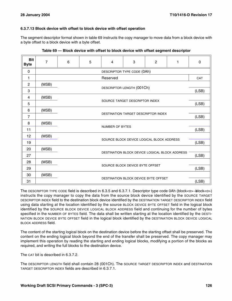
28 January 2004 T10/1416-D Revision 17
6.3.7.13 Block device with offset to block device with offset operation
The segment descriptor format shown in table 69 instructs the copy manager to move data from a block device witha byte offset to a block device with a byte offset.
The DESCRIPTOR TYPE CODE field is described in 6.3.5 and 6.3.7.1. Descriptor type code 0Ah (block<o>→block<o>)instructs the copy manager to copy the data from the source block device identified by the SOURCE TARGET
DESCRIPTOR INDEX field to the destination block device identified by the DESTINATION TARGET DESCRIPTOR INDEX fieldusing data starting at the location identified by the source BLOCK DEVICE BYTE OFFSET field in the logical blockidentified by the SOURCE BLOCK DEVICE LOGICAL BLOCK ADDRESS field and continuing for the number of bytesspecified in the NUMBER OF BYTES field. The data shall be written starting at the location identified by the DESTI-NATION BLOCK DEVICE BYTE OFFSET field in the logical block identified by the DESTINATION BLOCK DEVICE LOGICAL
BLOCK ADDRESS field.
The content of the starting logical block on the destination device before the starting offset shall be preserved. Thecontent on the ending logical block beyond the end of the transfer shall be preserved. The copy manager mayimplement this operation by reading the starting and ending logical blocks, modifying a portion of the blocks asrequired, and writing the full blocks to the destination device.
The CAT bit is described in 6.3.7.2.
The DESCRIPTOR LENGTH field shall contain 28 (001Ch). The SOURCE TARGET DESCRIPTOR INDEX and DESTINATION
TARGET DESCRIPTOR INDEX fields are described in 6.3.7.1.
Table 69 — Block device with offset to block device with offset segment descriptor
BitByte
7 6 5 4 3 2 1 0
0 DESCRIPTOR TYPE CODE (0Ah)
1 Reserved CAT
2 (MSB)DESCRIPTOR LENGTH (001Ch)
3 (LSB)
4 (MSB)SOURCE TARGET DESCRIPTOR INDEX
5 (LSB)
6 (MSB)DESTINATION TARGET DESCRIPTOR INDEX
7 (LSB)
8 (MSB)NUMBER OF BYTES
11 (LSB)
12 (MSB)SOURCE BLOCK DEVICE LOGICAL BLOCK ADDRESS
19 (LSB)
20 (MSB)DESTINATION BLOCK DEVICE LOGICAL BLOCK ADDRESS
27 (LSB)
28 (MSB)SOURCE BLOCK DEVICE BYTE OFFSET
29 (LSB)
30 (MSB)DESTINATION BLOCK DEVICE BYTE OFFSET
31 (LSB)
Working Draft SCSI Primary Commands - 3 (SPC-3) 126
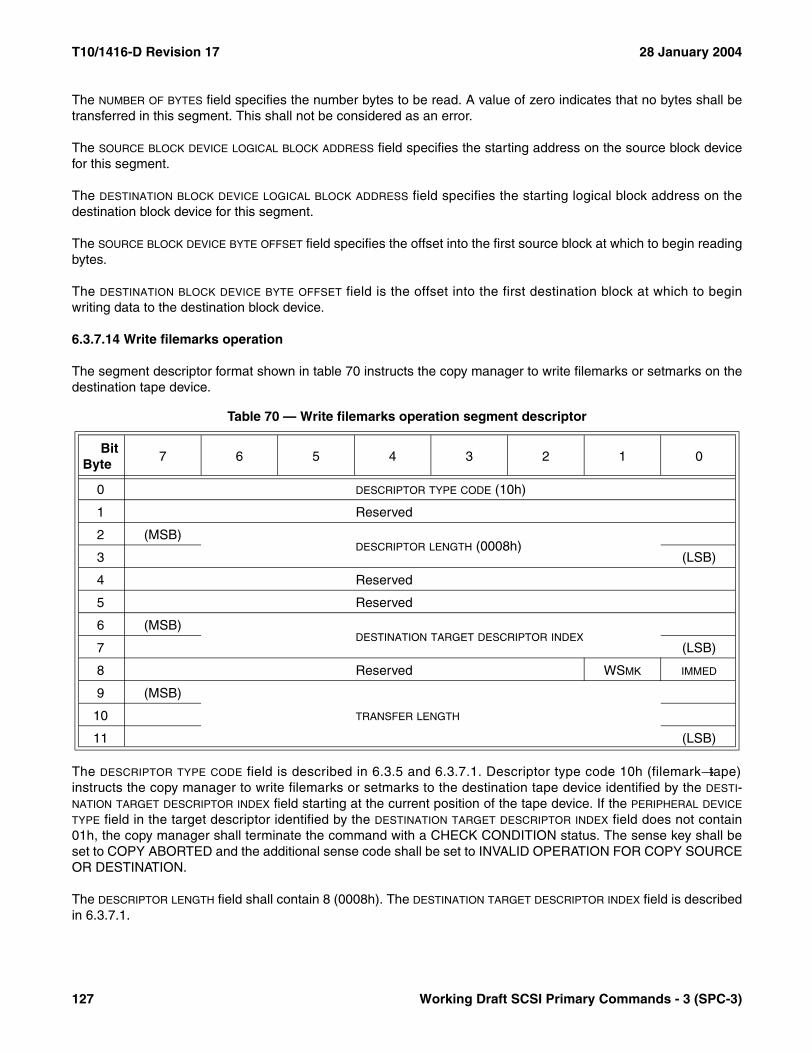
T10/1416-D Revision 17 28 January 2004
The NUMBER OF BYTES field specifies the number bytes to be read. A value of zero indicates that no bytes shall betransferred in this segment. This shall not be considered as an error.
The SOURCE BLOCK DEVICE LOGICAL BLOCK ADDRESS field specifies the starting address on the source block devicefor this segment.
The DESTINATION BLOCK DEVICE LOGICAL BLOCK ADDRESS field specifies the starting logical block address on thedestination block device for this segment.
The SOURCE BLOCK DEVICE BYTE OFFSET field specifies the offset into the first source block at which to begin readingbytes.
The DESTINATION BLOCK DEVICE BYTE OFFSET field is the offset into the first destination block at which to beginwriting data to the destination block device.
6.3.7.14 Write filemarks operation
The segment descriptor format shown in table 70 instructs the copy manager to write filemarks or setmarks on thedestination tape device.
The DESCRIPTOR TYPE CODE field is described in 6.3.5 and 6.3.7.1. Descriptor type code 10h (filemark→tape)instructs the copy manager to write filemarks or setmarks to the destination tape device identified by the DESTI-NATION TARGET DESCRIPTOR INDEX field starting at the current position of the tape device. If the PERIPHERAL DEVICE
TYPE field in the target descriptor identified by the DESTINATION TARGET DESCRIPTOR INDEX field does not contain01h, the copy manager shall terminate the command with a CHECK CONDITION status. The sense key shall beset to COPY ABORTED and the additional sense code shall be set to INVALID OPERATION FOR COPY SOURCEOR DESTINATION.
The DESCRIPTOR LENGTH field shall contain 8 (0008h). The DESTINATION TARGET DESCRIPTOR INDEX field is describedin 6.3.7.1.
Table 70 — Write filemarks operation segment descriptor
BitByte
7 6 5 4 3 2 1 0
0 DESCRIPTOR TYPE CODE (10h)
1 Reserved
2 (MSB)DESCRIPTOR LENGTH (0008h)
3 (LSB)
4 Reserved
5 Reserved
6 (MSB)DESTINATION TARGET DESCRIPTOR INDEX
7 (LSB)
8 Reserved WSMK IMMED
9 (MSB)
TRANSFER LENGTH10
11 (LSB)
127 Working Draft SCSI Primary Commands - 3 (SPC-3)
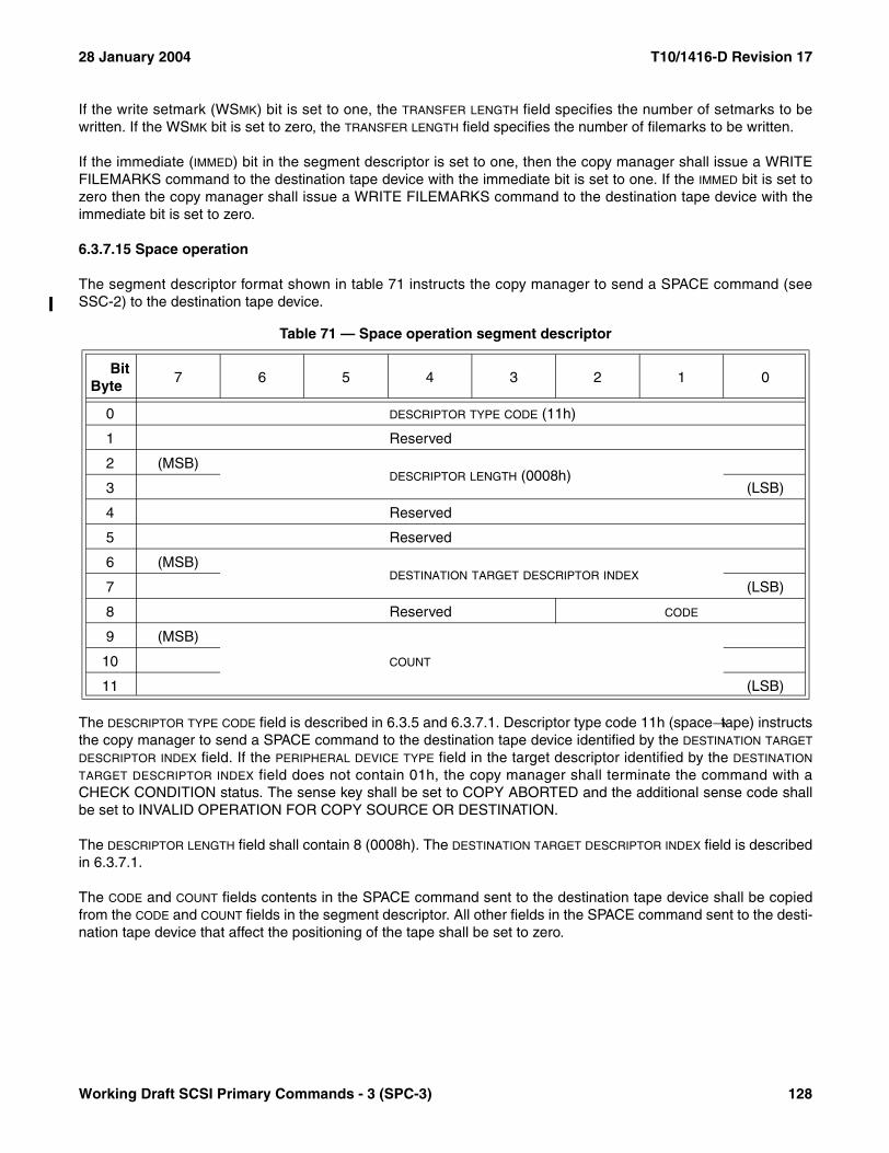
28 January 2004 T10/1416-D Revision 17
If the write setmark (WSMK) bit is set to one, the TRANSFER LENGTH field specifies the number of setmarks to bewritten. If the WSMK bit is set to zero, the TRANSFER LENGTH field specifies the number of filemarks to be written.
If the immediate (IMMED) bit in the segment descriptor is set to one, then the copy manager shall issue a WRITEFILEMARKS command to the destination tape device with the immediate bit is set to one. If the IMMED bit is set tozero then the copy manager shall issue a WRITE FILEMARKS command to the destination tape device with theimmediate bit is set to zero.
6.3.7.15 Space operation
The segment descriptor format shown in table 71 instructs the copy manager to send a SPACE command (seeSSC-2) to the destination tape device.
The DESCRIPTOR TYPE CODE field is described in 6.3.5 and 6.3.7.1. Descriptor type code 11h (space→tape) instructsthe copy manager to send a SPACE command to the destination tape device identified by the DESTINATION TARGET
DESCRIPTOR INDEX field. If the PERIPHERAL DEVICE TYPE field in the target descriptor identified by the DESTINATION
TARGET DESCRIPTOR INDEX field does not contain 01h, the copy manager shall terminate the command with aCHECK CONDITION status. The sense key shall be set to COPY ABORTED and the additional sense code shallbe set to INVALID OPERATION FOR COPY SOURCE OR DESTINATION.
The DESCRIPTOR LENGTH field shall contain 8 (0008h). The DESTINATION TARGET DESCRIPTOR INDEX field is describedin 6.3.7.1.
The CODE and COUNT fields contents in the SPACE command sent to the destination tape device shall be copiedfrom the CODE and COUNT fields in the segment descriptor. All other fields in the SPACE command sent to the desti-nation tape device that affect the positioning of the tape shall be set to zero.
Table 71 — Space operation segment descriptor
BitByte
7 6 5 4 3 2 1 0
0 DESCRIPTOR TYPE CODE (11h)
1 Reserved
2 (MSB)DESCRIPTOR LENGTH (0008h)
3 (LSB)
4 Reserved
5 Reserved
6 (MSB)DESTINATION TARGET DESCRIPTOR INDEX
7 (LSB)
8 Reserved CODE
9 (MSB)
COUNT10
11 (LSB)
Working Draft SCSI Primary Commands - 3 (SPC-3) 128

T10/1416-D Revision 17 28 January 2004
6.3.7.16 Locate operation
The segment descriptor format shown in table 72 instructs the copy manager to send a LOCATE command (seeSSC-2) to the destination tape device.
The DESCRIPTOR TYPE CODE field is described in 6.3.5 and 6.3.7.1. Descriptor type code 12h (locate→tape) instructsthe copy manager to send a LOCATE command to the destination tape device identified by the DESTINATION TARGET
DESCRIPTOR INDEX field. If the PERIPHERAL DEVICE TYPE field in the target descriptor identified by the DESTINATION
TARGET DESCRIPTOR INDEX field does not contain 01h, the copy manager shall terminate the command with aCHECK CONDITION status. The sense key shall be set to COPY ABORTED and the additional sense code shallbe set to INVALID OPERATION FOR COPY SOURCE OR DESTINATION.
The DESCRIPTOR LENGTH field shall contain 8 (0008h). The DESTINATION TARGET DESCRIPTOR INDEX field is describedin 6.3.7.1.
The BLOCK ADDRESS field contents in the LOCATE command sent to the destination tape device shall be copiedfrom the BLOCK ADDRESS field in the segment descriptor. All other fields in the LOCATE command sent to the desti-nation tape device that affect the positioning of the tape shall be set to zero.
NOTE 18 - The restrictions described above for the LOCATE command limit the operation to locating SCSI logicalblock addresses in the current tape partition.
Table 72 — Locate operation segment descriptor
BitByte
7 6 5 4 3 2 1 0
0 DESCRIPTOR TYPE CODE (12h)
1 Reserved
2 (MSB)DESCRIPTOR LENGTH (0008h)
3 (LSB)
4 Reserved
5 Reserved
6 (MSB)DESTINATION TARGET DESCRIPTOR INDEX
7 (LSB)
8 (MSB)BLOCK ADDRESS
11 (LSB)
129 Working Draft SCSI Primary Commands - 3 (SPC-3)
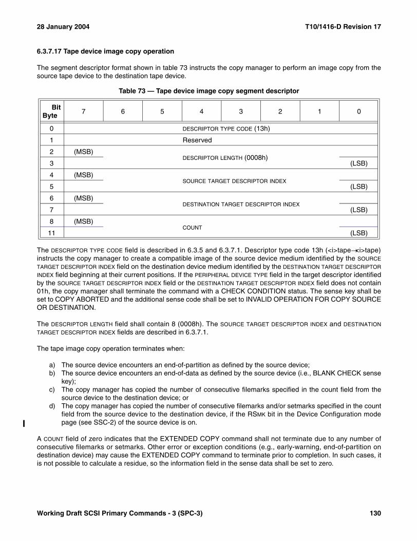
28 January 2004 T10/1416-D Revision 17
6.3.7.17 Tape device image copy operation
The segment descriptor format shown in table 73 instructs the copy manager to perform an image copy from thesource tape device to the destination tape device.
The DESCRIPTOR TYPE CODE field is described in 6.3.5 and 6.3.7.1. Descriptor type code 13h (<i>tape→<i>tape)instructs the copy manager to create a compatible image of the source device medium identified by the SOURCE
TARGET DESCRIPTOR INDEX field on the destination device medium identified by the DESTINATION TARGET DESCRIPTOR
INDEX field beginning at their current positions. If the PERIPHERAL DEVICE TYPE field in the target descriptor identifiedby the SOURCE TARGET DESCRIPTOR INDEX field or the DESTINATION TARGET DESCRIPTOR INDEX field does not contain01h, the copy manager shall terminate the command with a CHECK CONDITION status. The sense key shall beset to COPY ABORTED and the additional sense code shall be set to INVALID OPERATION FOR COPY SOURCEOR DESTINATION.
The DESCRIPTOR LENGTH field shall contain 8 (0008h). The SOURCE TARGET DESCRIPTOR INDEX and DESTINATION
TARGET DESCRIPTOR INDEX fields are described in 6.3.7.1.
The tape image copy operation terminates when:
a) The source device encounters an end-of-partition as defined by the source device;b) The source device encounters an end-of-data as defined by the source device (i.e., BLANK CHECK sense
key);c) The copy manager has copied the number of consecutive filemarks specified in the count field from the
source device to the destination device; ord) The copy manager has copied the number of consecutive filemarks and/or setmarks specified in the count
field from the source device to the destination device, if the RSMK bit in the Device Configuration modepage (see SSC-2) of the source device is on.
A COUNT field of zero indicates that the EXTENDED COPY command shall not terminate due to any number ofconsecutive filemarks or setmarks. Other error or exception conditions (e.g., early-warning, end-of-partition ondestination device) may cause the EXTENDED COPY command to terminate prior to completion. In such cases, itis not possible to calculate a residue, so the information field in the sense data shall be set to zero.
Table 73 — Tape device image copy segment descriptor
BitByte
7 6 5 4 3 2 1 0
0 DESCRIPTOR TYPE CODE (13h)
1 Reserved
2 (MSB)DESCRIPTOR LENGTH (0008h)
3 (LSB)
4 (MSB)SOURCE TARGET DESCRIPTOR INDEX
5 (LSB)
6 (MSB)DESTINATION TARGET DESCRIPTOR INDEX
7 (LSB)
8 (MSB)COUNT
11 (LSB)
Working Draft SCSI Primary Commands - 3 (SPC-3) 130
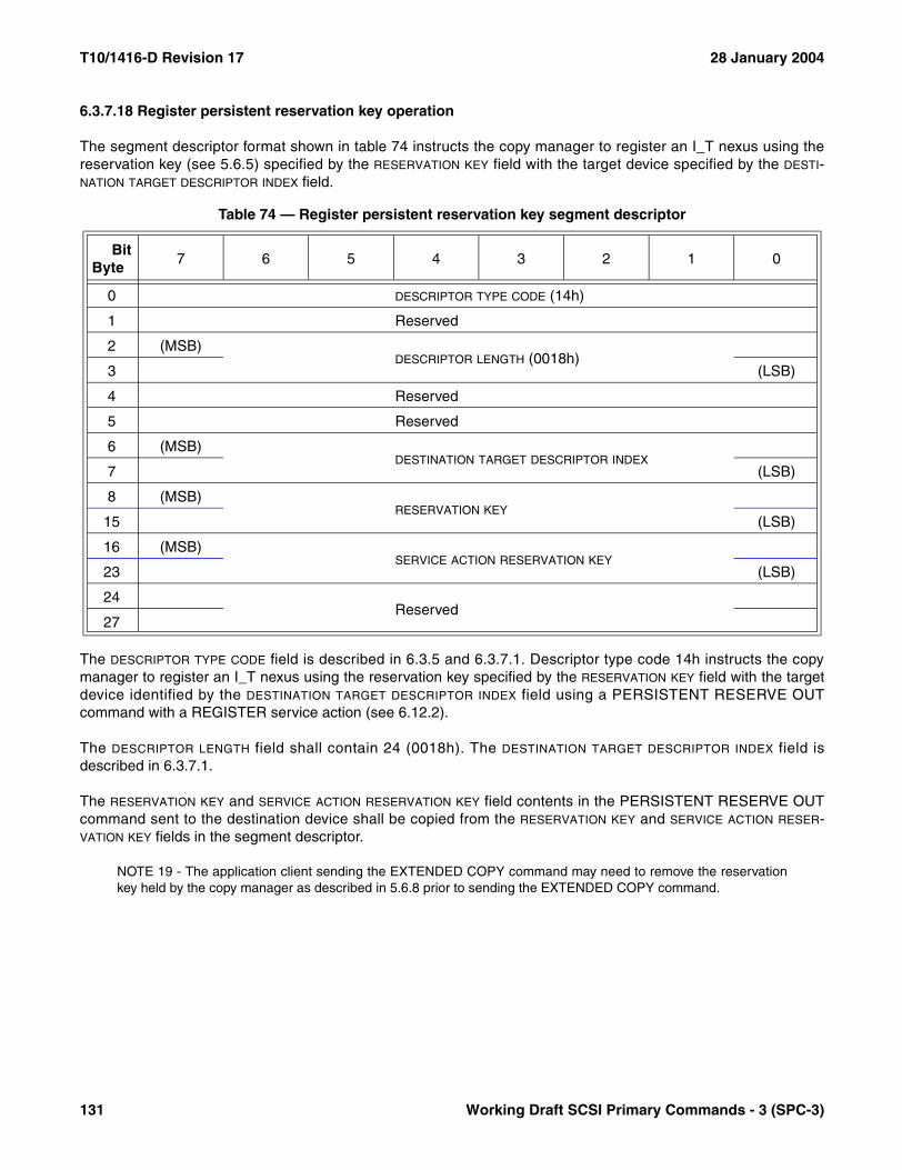
T10/1416-D Revision 17 28 January 2004
6.3.7.18 Register persistent reservation key operation
The segment descriptor format shown in table 74 instructs the copy manager to register an I_T nexus using thereservation key (see 5.6.5) specified by the RESERVATION KEY field with the target device specified by the DESTI-NATION TARGET DESCRIPTOR INDEX field.
The DESCRIPTOR TYPE CODE field is described in 6.3.5 and 6.3.7.1. Descriptor type code 14h instructs the copymanager to register an I_T nexus using the reservation key specified by the RESERVATION KEY field with the targetdevice identified by the DESTINATION TARGET DESCRIPTOR INDEX field using a PERSISTENT RESERVE OUTcommand with a REGISTER service action (see 6.12.2).
The DESCRIPTOR LENGTH field shall contain 24 (0018h). The DESTINATION TARGET DESCRIPTOR INDEX field isdescribed in 6.3.7.1.
The RESERVATION KEY and SERVICE ACTION RESERVATION KEY field contents in the PERSISTENT RESERVE OUTcommand sent to the destination device shall be copied from the RESERVATION KEY and SERVICE ACTION RESER-VATION KEY fields in the segment descriptor.
NOTE 19 - The application client sending the EXTENDED COPY command may need to remove the reservationkey held by the copy manager as described in 5.6.8 prior to sending the EXTENDED COPY command.
Table 74 — Register persistent reservation key segment descriptor
BitByte
7 6 5 4 3 2 1 0
0 DESCRIPTOR TYPE CODE (14h)
1 Reserved
2 (MSB)DESCRIPTOR LENGTH (0018h)
3 (LSB)
4 Reserved
5 Reserved
6 (MSB)DESTINATION TARGET DESCRIPTOR INDEX
7 (LSB)
8 (MSB)RESERVATION KEY
15 (LSB)
16 (MSB)SERVICE ACTION RESERVATION KEY
23 (LSB)
24Reserved
27
131 Working Draft SCSI Primary Commands - 3 (SPC-3)
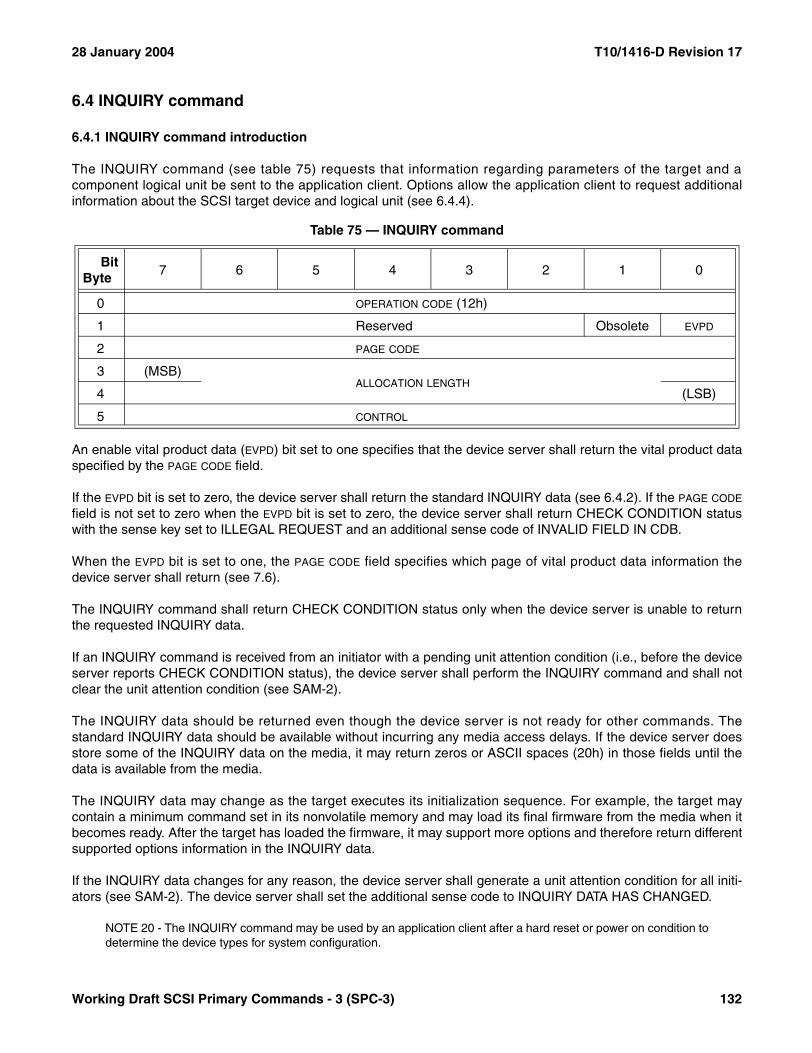
28 January 2004 T10/1416-D Revision 17
6.4 INQUIRY command
6.4.1 INQUIRY command introduction
The INQUIRY command (see table 75) requests that information regarding parameters of the target and acomponent logical unit be sent to the application client. Options allow the application client to request additionalinformation about the SCSI target device and logical unit (see 6.4.4).
An enable vital product data (EVPD) bit set to one specifies that the device server shall return the vital product dataspecified by the PAGE CODE field.
If the EVPD bit is set to zero, the device server shall return the standard INQUIRY data (see 6.4.2). If the PAGE CODE
field is not set to zero when the EVPD bit is set to zero, the device server shall return CHECK CONDITION statuswith the sense key set to ILLEGAL REQUEST and an additional sense code of INVALID FIELD IN CDB.
When the EVPD bit is set to one, the PAGE CODE field specifies which page of vital product data information thedevice server shall return (see 7.6).
The INQUIRY command shall return CHECK CONDITION status only when the device server is unable to returnthe requested INQUIRY data.
If an INQUIRY command is received from an initiator with a pending unit attention condition (i.e., before the deviceserver reports CHECK CONDITION status), the device server shall perform the INQUIRY command and shall notclear the unit attention condition (see SAM-2).
The INQUIRY data should be returned even though the device server is not ready for other commands. Thestandard INQUIRY data should be available without incurring any media access delays. If the device server doesstore some of the INQUIRY data on the media, it may return zeros or ASCII spaces (20h) in those fields until thedata is available from the media.
The INQUIRY data may change as the target executes its initialization sequence. For example, the target maycontain a minimum command set in its nonvolatile memory and may load its final firmware from the media when itbecomes ready. After the target has loaded the firmware, it may support more options and therefore return differentsupported options information in the INQUIRY data.
If the INQUIRY data changes for any reason, the device server shall generate a unit attention condition for all initi-ators (see SAM-2). The device server shall set the additional sense code to INQUIRY DATA HAS CHANGED.
NOTE 20 - The INQUIRY command may be used by an application client after a hard reset or power on condition todetermine the device types for system configuration.
Table 75 — INQUIRY command
BitByte
7 6 5 4 3 2 1 0
0 OPERATION CODE (12h)
1 Reserved Obsolete EVPD
2 PAGE CODE
3 (MSB)ALLOCATION LENGTH
4 (LSB)
5 CONTROL
Working Draft SCSI Primary Commands - 3 (SPC-3) 132
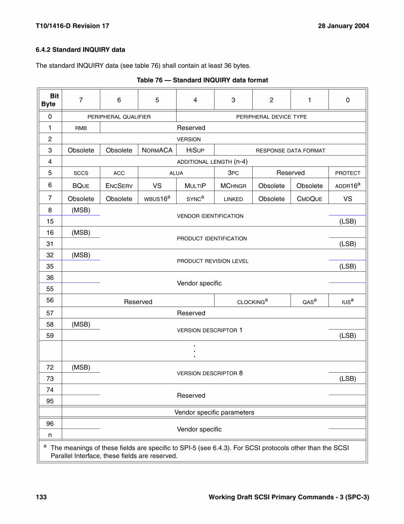
T10/1416-D Revision 17 28 January 2004
6.4.2 Standard INQUIRY data
The standard INQUIRY data (see table 76) shall contain at least 36 bytes.
Table 76 — Standard INQUIRY data format
BitByte
7 6 5 4 3 2 1 0
0 PERIPHERAL QUALIFIER PERIPHERAL DEVICE TYPE
1 RMB Reserved
2 VERSION
3 Obsolete Obsolete NORMACA HISUP RESPONSE DATA FORMAT
4 ADDITIONAL LENGTH (n-4)
5 SCCS ACC ALUA 3PC Reserved PROTECT
6 BQUE ENCSERV VS MULTIP MCHNGR Obsolete Obsolete ADDR16a
7 Obsolete Obsolete WBUS16a SYNCa LINKED Obsolete CMDQUE VS
8 (MSB)VENDOR IDENTIFICATION
15 (LSB)
16 (MSB)PRODUCT IDENTIFICATION
31 (LSB)
32 (MSB)PRODUCT REVISION LEVEL
35 (LSB)
36Vendor specific
55
56 Reserved CLOCKINGa QASa IUSa
57 Reserved
58 (MSB)VERSION DESCRIPTOR 1
59 (LSB)...
72 (MSB)VERSION DESCRIPTOR 8
73 (LSB)
74Reserved
95
Vendor specific parameters
96Vendor specific
n
a The meanings of these fields are specific to SPI-5 (see 6.4.3). For SCSI protocols other than the SCSI Parallel Interface, these fields are reserved.
133 Working Draft SCSI Primary Commands - 3 (SPC-3)
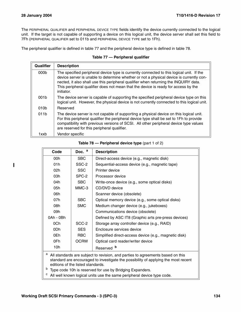
28 January 2004 T10/1416-D Revision 17
The PERIPHERAL QUALIFIER and PERIPHERAL DEVICE TYPE fields identify the device currently connected to the logicalunit. If the target is not capable of supporting a device on this logical unit, the device server shall set this field to7Fh (PERIPHERAL QUALIFIER set to 011b and PERIPHERAL DEVICE TYPE set to 1Fh).
The peripheral qualifier is defined in table 77 and the peripheral device type is defined in table 78.
Table 77 — Peripheral qualifier
Qualifier Description
000b The specified peripheral device type is currently connected to this logical unit. If the device server is unable to determine whether or not a physical device is currently con-nected, it also shall use this peripheral qualifier when returning the INQUIRY data. This peripheral qualifier does not mean that the device is ready for access by the initiator.
001b The device server is capable of supporting the specified peripheral device type on this logical unit. However, the physical device is not currently connected to this logical unit.
010b Reserved
011b The device server is not capable of supporting a physical device on this logical unit. For this peripheral qualifier the peripheral device type shall be set to 1Fh to provide compatibility with previous versions of SCSI. All other peripheral device type values are reserved for this peripheral qualifier.
1xxb Vendor specific
Table 78 — Peripheral device type (part 1 of 2)
Code Doc. a Description
00h SBC Direct-access device (e.g., magnetic disk)
01h SSC-2 Sequential-access device (e.g., magnetic tape)
02h SSC Printer device
03h SPC-2 Processor device
04h SBC Write-once device (e.g., some optical disks)
05h MMC-3 CD/DVD device
06h Scanner device (obsolete)
07h SBC Optical memory device (e.g., some optical disks)
08h SMC Medium changer device (e.g., jukeboxes)
09h Communications device (obsolete)
0Ah - 0Bh Defined by ASC IT8 (Graphic arts pre-press devices)
0Ch SCC-2 Storage array controller device (e.g., RAID)
0Dh SES Enclosure services device
0Eh RBC Simplified direct-access device (e.g., magnetic disk)
0Fh OCRW Optical card reader/writer device
10h Reserved b
a All standards are subject to revision, and parties to agreements based on this standard are encouraged to investigate the possibility of applying the most recent editions of the listed standards.
b Type code 10h is reserved for use by Bridging Expanders.c All well known logical units use the same peripheral device type code.
Working Draft SCSI Primary Commands - 3 (SPC-3) 134
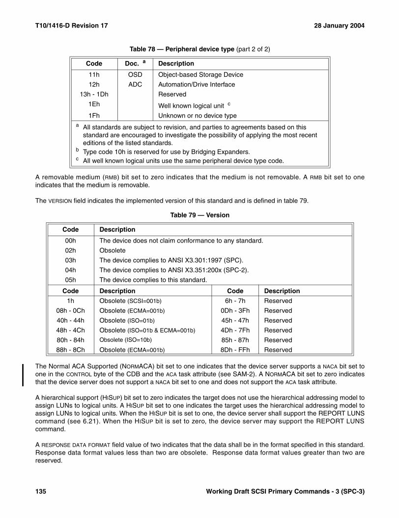
T10/1416-D Revision 17 28 January 2004
A removable medium (RMB) bit set to zero indicates that the medium is not removable. A RMB bit set to oneindicates that the medium is removable.
The VERSION field indicates the implemented version of this standard and is defined in table 79.
The Normal ACA Supported (NORMACA) bit set to one indicates that the device server supports a NACA bit set toone in the CONTROL byte of the CDB and the ACA task attribute (see SAM-2). A NORMACA bit set to zero indicatesthat the device server does not support a NACA bit set to one and does not support the ACA task attribute.
A hierarchical support (HISUP) bit set to zero indicates the target does not use the hierarchical addressing model toassign LUNs to logical units. A HISUP bit set to one indicates the target uses the hierarchical addressing model toassign LUNs to logical units. When the HISUP bit is set to one, the device server shall support the REPORT LUNScommand (see 6.21). When the HISUP bit is set to zero, the device server may support the REPORT LUNScommand.
A RESPONSE DATA FORMAT field value of two indicates that the data shall be in the format specified in this standard.Response data format values less than two are obsolete. Response data format values greater than two arereserved.
11h OSD Object-based Storage Device
12h ADC Automation/Drive Interface
13h - 1Dh Reserved
1Eh Well known logical unit c
1Fh Unknown or no device type
Table 79 — Version
Code Description
00h The device does not claim conformance to any standard.
02h Obsolete
03h The device complies to ANSI X3.301:1997 (SPC).
04h The device complies to ANSI X3.351:200x (SPC-2).
05h The device complies to this standard.
Code Description Code Description
1h Obsolete (SCSI=001b) 6h - 7h Reserved
08h - 0Ch Obsolete (ECMA=001b) 0Dh - 3Fh Reserved
40h - 44h Obsolete (ISO=01b) 45h - 47h Reserved
48h - 4Ch Obsolete (ISO=01b & ECMA=001b) 4Dh - 7Fh Reserved
80h - 84h Obsolete (ISO=10b) 85h - 87h Reserved
88h - 8Ch Obsolete (ECMA=001b) 8Dh - FFh Reserved
Table 78 — Peripheral device type (part 2 of 2)
Code Doc. a Description
a All standards are subject to revision, and parties to agreements based on this standard are encouraged to investigate the possibility of applying the most recent editions of the listed standards.
b Type code 10h is reserved for use by Bridging Expanders.c All well known logical units use the same peripheral device type code.
135 Working Draft SCSI Primary Commands - 3 (SPC-3)

28 January 2004 T10/1416-D Revision 17
The ADDITIONAL LENGTH field shall specify the length in bytes of the parameters. If the ALLOCATION LENGTH of theCDB is too small to transfer all of the parameters, the ADDITIONAL LENGTH shall not be adjusted to reflect thetruncation.
An SCC Supported (SCCS) bit set to one indicates that the device contains an embedded storage array controllercomponent. See SCC-2 for details about storage array controller devices. An SCCS bit set to zero indicates that thedevice does not contain an embedded storage array controller component.
An Access Controls Coordinator (ACC) bit set to one indicates that the device contains an access controls coordi-nator (see 3.1.4) that may be addressed through this logical unit. An ACC bit set to zero indicates that no accesscontrols coordinator may be addressed through this logical unit. If the device contains an access controls coordi-nator that may be addressed through any logical unit other than the ACCESS CONTROLS well known logical unit(see 8.3), the ACC bit shall be set to one for LUN 0.
The contents of the asymmetric logical unit access (ALUA) field (see table 80) indicate the support for asymmetriclogical unit access (see 5.8).
A Third-Party Copy (3PC) bit set to one indicates that the device supports third-party copy commands such as theEXTENDED COPY command (see 6.3). A 3PC bit set to zero indicates that the device does not support suchcommands.
A PROTECT bit set to zero indicates that the logical unit does not support protection information (see SBC-2). APROTECT bit set to one indicates that the logical unit supports protection information.
The BQUE bit combines with the CMDQUE bit to indicate whether the logical unit supports the full task managementmodel or the basic task management model as described in table 81.
An Enclosure Services (ENCSERV) bit set to one indicates that the device contains an embedded enclosureservices component. See SES for details about enclosure services, including a device model for an embeddedenclosure services device. An ENCSERV bit set to zero indicates that the device does not contain an embeddedenclosure services component.
A Multi Port (MULTIP) bit set to one indicates that this is a multi-port (two or more ports) device and conforms to theSCSI multi-port device requirements found in the applicable standards (e.g., SAM-2, a SCSI protocol standard and
Table 80 — ALUA field contents
Value Description
00b The SCSI target device does not support asymmetric logical unit access or supports a form of asymmetric access that is vendor specific. Neither the REPORT TARGET GROUPS nor the SET TARGET GROUPS commands is supported.
01b Only implicit asymmetric logical unit access (see 5.8.6) is supported. The SCSI target device is capable of changing target port asymmetric access states without a SET TARGET PORT GROUPS command. The REPORT TARGET PORT GROUPS command is supported and the SET TARGET PORT GROUPS command is not supported.
10b Only explicit asymmetric logical unit access (see 5.8.7) is supported. The SCSI target device only changes target port asymmetric access states as requested with the SET TARGET PORT GROUPS command. Both the REPORT TARGET PORT GROUPS command and the SET TARGET PORT GROUPS command are supported.
11b Both explicit and implicit asymmetric logical unit access are supported. Both the REPORT TARGET PORT GROUPS command and the SET TARGET PORT GROUPS commands are supported.
Working Draft SCSI Primary Commands - 3 (SPC-3) 136

T10/1416-D Revision 17 28 January 2004
possibly provisions of a command set standard). A MULTIP bit set to zero indicates that this device has a single portand does not implement the multi-port requirements.
A medium changer (MCHNGR) bit set to one indicates that the device is associated with or attached to a mediumtransport element. See 5.10 and SMC for details about medium changers, including a device model for an attachedmedium changer device. The MCHNGR bit is valid only when the RMB bit is equal to one. A MCHNGR bit set to zeroindicates that the device is not embedded within or attached to a medium transport element.
A linked command (LINKED) bit set to one indicates that the device server supports linked commands (see SAM-2).A LINKED bit set to zero indicates the device server does not support linked commands.
The CMDQUE bit and BQUE bit indicate whether the logical unit supports the full task management model (seeSAM-3) or the basic task management model (see SAM-3) as described in table 81.
The VENDOR IDENTIFICATION field contains eight bytes of left-aligned ASCII data (see 4.4.1) identifying the vendor ofthe product. The vendor identification shall be one assigned by INCITS. A list of assigned vendor identifications isin Annex D and on the T10 web site (www.T10.org).
NOTE 21 - The T10 web site (www.t10.org) provides a convenient means to request an identification code.
The PRODUCT IDENTIFICATION field contains sixteen bytes of left-aligned ASCII data (see 4.4.1) defined by thevendor.
The PRODUCT REVISION LEVEL field contains four bytes of left-aligned ASCII data defined by the vendor.
Table 81 — BQUE and CMDQUE bits definition
BQUE CMDQUE Description
0 0 Obsolete
0 1 Full task management model supported
1 0 Basic task management model supported
1 1 Illegal combination of BQUE and CMDQUE bits
137 Working Draft SCSI Primary Commands - 3 (SPC-3)

28 January 2004 T10/1416-D Revision 17
The VERSION DESCRIPTOR fields provide for identifying up to eight standards to which the device claimsconformance. The value in each VERSION DESCRIPTOR field shall be selected from table 82. All version descriptorvalues not listed in table 82 are reserved. Technical Committee T10 of INCITS maintains an electronic copy of theinformation in table 82 on its world wide web site (http://www.t10.org/). In the event that the T10 world wide web siteis no longer active, access may be possible via the INCITS world wide web site (http://www.incits.org), the ANSIworld wide web site (http://www.ansi.org), the IEC site (http://www.iec.ch/), the ISO site (http://www.iso.ch/), or theISO/IEC JTC 1 web site (http://www.jtc1.org/). It is recommended that the first version descriptor be used for theSCSI architecture standard, followed by the physical standard if any, followed by the SCSI protocol, followed by theappropriate SPC version, followed by the device type command set, followed by a secondary command set if any.
Table 82 — Version descriptor values (part 1 of 6)
Standard
Version Descriptor
Value
ADC (no version claimed) 03C0h
ADC T10/1558-D revision 6 03D5h
ADP (no version claimed) 09C0h
ADT (no version claimed) 09E0h
ATA/ATAPI-6 (no version claimed) 15E0h
ATA/ATAPI-6 ANSI INCITS.361:2002 15FDh
ATA/ATAPI-7 (no version claimed) 1600h
ATA/ATAPI-7 T13/1532-D revision 3 1602h
EPI (no version claimed) 0B20h
EPI ANSI NCITS TR-23:1999 0B3Ch
EPI T10/1134 revision 16 0B3Bh
Fast-20 (no version claimed) 0AC0h
Fast-20 ANSI X3.277:1996 0ADCh
Fast-20 T10/1071 revision 06 0ADBh
FC-AL (no version claimed) 0D40h
FC-AL ANSI X3.272:1996 0D5Ch
FC-AL-2 (no version claimed) 0D60h
FC-AL-2 ANSI NCITS.332:1999 0D7Ch
FC-AL-2 ANSI NCITS.332:1999 with Amnd 1 AM1:2002 0D7Dh
FC-AL-2 T11/1133-D revision 7.0 0D61h
FC-FLA (no version claimed) 1320h
FC-FLA ANSI NCITS TR-20:1998 133Ch
FC-FLA T11/1235 revision 7 133Bh
FC-FS (no version claimed) 0DA0h
FC-FS ANSI INCITS.373-2003 0DBCh
FC-FS T11/1331-D revision 1.2 0DB7h
FC-FS T11/1331-D revision 1.7 0DB8h
FCP (no version claimed) 08C0h
FCP ANSI X3.269:1996 08DCh
FCP T10/0993-D revision 12 08DBh
Annex C contains the version descriptor value assignments in numeric order.
Working Draft SCSI Primary Commands - 3 (SPC-3) 138

T10/1416-D Revision 17 28 January 2004
FC-PH (no version claimed) 0D20h
FC-PH ANSI X3.230:1994 0D3Bh
FC-PH ANSI X3.230:1994 with Amnd 1 ANSI X3.230/AM1:1996 0D3Ch
FC-PH-3 (no version claimed) 0D80h
FC-PH-3 ANSI X3.303-1998 0D9Ch
FC-PI (no version claimed) 0DC0h
FC-PI ANSI INCITS.352:2002 0DDCh
FC-PLDA (no version claimed) 1340h
FC-PLDA ANSI NCITS TR-19:1998 135Ch
FC-PLDA T11/1162 revision 2.1 135Bh
FCP-2 (no version claimed) 0900h
FCP-2 ANSI INCITS.350:2003 0917h
FCP-2 T10/1144-D revision 8 0918h
FCP-2 T10/1144-D revision 4 0901h
FCP-2 T10/1144-D revision 7 0915h
FCP-2 T10/1144-D revision 7a 0916h
FCP-3 (no version claimed) 0A00h
FC-Tape (no version claimed) 1300h
FC-Tape ANSI NCITS TR-24:1999 131Ch
FC-Tape T11/1315 revision 1.17 131Bh
FC-Tape T11/1315 revision 1.16 1301h
IEEE 1394 (no version claimed) 14A0h
ANSI IEEE 1394:1995 14BDh
IEEE 1394a (no version claimed) 14C0h
IEEE 1394b (no version claimed) 14E0h
iSCSI (no version claimed) 0960h
MMC (no version claimed) 0140h
MMC ANSI X3.304:1997 015Ch
MMC T10/1048-D revision 10a 015Bh
MMC-2 (no version claimed) 0240h
MMC-2 ANSI NCITS.333:2000 025Ch
MMC-2 T10/1228-D revision 11a 025Bh
MMC-2 T10/1228-D revision 11 0255h
MMC-3 (no version claimed) 02A0h
MMC-3 ANSI INCITS.360:2002 02B8h
MMC-3 T10/1363-D revision 10g 02B6h
MMC-3 T10/1363-D revision 9 02B5h
MMC-4 (no version claimed) 03A0h
Table 82 — Version descriptor values (part 2 of 6)
Standard
Version Descriptor
Value
Annex C contains the version descriptor value assignments in numeric order.
139 Working Draft SCSI Primary Commands - 3 (SPC-3)

28 January 2004 T10/1416-D Revision 17
MMC-5 (no version claimed) 0420h
MSC (no version claimed) 0380h
OCRW (no version claimed) 0280h
OCRW ISO/IEC 14776-381 029Eh
OSD (no version claimed) 0340h
OSD T10/1355-D revision 0 0341h
OSD T10/1355-D revision 7a 0342h
OSD T10/1355-D revision 8 0343h
OSD T10/1355-D revision 9 0344h
RBC (no version claimed) 0220h
RBC ANSI NCITS.330:2000 023Ch
RBC T10/1240-D revision 10a 0238h
SAM (no version claimed) 0020h
SAM ANSI X3.270:1996 003Ch
SAM T10/0994-D revision 18 003Bh
SAM-2 (no version claimed) 0040h
SAM-2 ANSI INCITS.366:2003 005Ch
SAM-2 T10/1157-D revision 24 0055h
SAM-2 T10/1157-D revision 23 0054h
SAM-3 (no version claimed) 0060h
SAM-3 T10/1561-D revision 7 0062h
SAS (no version claimed) 0BE0h
SAS ANSI INCITS.376:2003 0BFDh
SAS T10/1562-D revision 05 0BFCh
SAS T10/1562-D revision 01 0BE1h
SAS T10/1562-D revision 03 0BF5h
SAS T10/1562-D revision 04 0BFAh
SAS T10/1562-D revision 04 0BFBh
SAS-1.1 (no version claimed) 0C00h
SBC (no version claimed) 0180h
SBC ANSI NCITS.306:1998 019Ch
SBC T10/0996-D revision 08c 019Bh
SBC-2 (no version claimed) 0320h
SBC-2 T10/1417-D revision 5a 0322h
SBP-2 (no version claimed) 08E0h
SBP-2 ANSI NCITS.325:1999 08FCh
SBP-2 T10/1155-D revision 04 08FBh
SBP-3 (no version claimed) 0980h
Table 82 — Version descriptor values (part 3 of 6)
Standard
Version Descriptor
Value
Annex C contains the version descriptor value assignments in numeric order.
Working Draft SCSI Primary Commands - 3 (SPC-3) 140
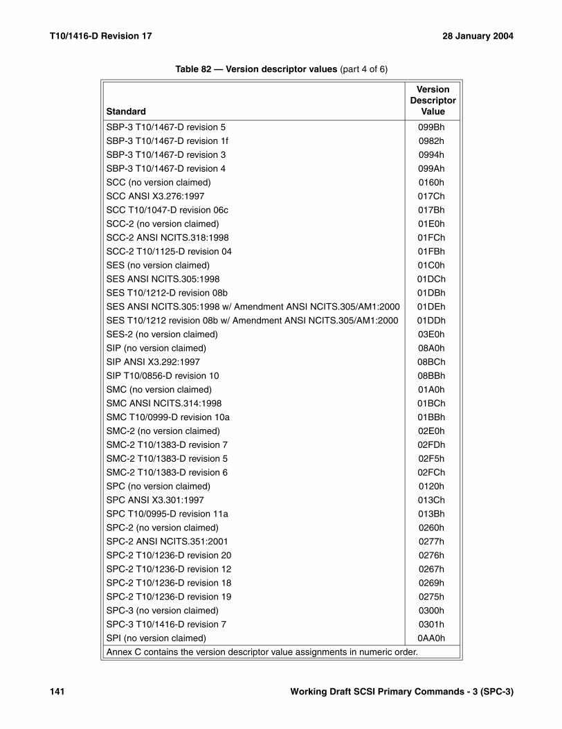
T10/1416-D Revision 17 28 January 2004
SBP-3 T10/1467-D revision 5 099Bh
SBP-3 T10/1467-D revision 1f 0982h
SBP-3 T10/1467-D revision 3 0994h
SBP-3 T10/1467-D revision 4 099Ah
SCC (no version claimed) 0160h
SCC ANSI X3.276:1997 017Ch
SCC T10/1047-D revision 06c 017Bh
SCC-2 (no version claimed) 01E0h
SCC-2 ANSI NCITS.318:1998 01FCh
SCC-2 T10/1125-D revision 04 01FBh
SES (no version claimed) 01C0h
SES ANSI NCITS.305:1998 01DCh
SES T10/1212-D revision 08b 01DBh
SES ANSI NCITS.305:1998 w/ Amendment ANSI NCITS.305/AM1:2000 01DEh
SES T10/1212 revision 08b w/ Amendment ANSI NCITS.305/AM1:2000 01DDh
SES-2 (no version claimed) 03E0h
SIP (no version claimed) 08A0h
SIP ANSI X3.292:1997 08BCh
SIP T10/0856-D revision 10 08BBh
SMC (no version claimed) 01A0h
SMC ANSI NCITS.314:1998 01BCh
SMC T10/0999-D revision 10a 01BBh
SMC-2 (no version claimed) 02E0h
SMC-2 T10/1383-D revision 7 02FDh
SMC-2 T10/1383-D revision 5 02F5h
SMC-2 T10/1383-D revision 6 02FCh
SPC (no version claimed) 0120h
SPC ANSI X3.301:1997 013Ch
SPC T10/0995-D revision 11a 013Bh
SPC-2 (no version claimed) 0260h
SPC-2 ANSI NCITS.351:2001 0277h
SPC-2 T10/1236-D revision 20 0276h
SPC-2 T10/1236-D revision 12 0267h
SPC-2 T10/1236-D revision 18 0269h
SPC-2 T10/1236-D revision 19 0275h
SPC-3 (no version claimed) 0300h
SPC-3 T10/1416-D revision 7 0301h
SPI (no version claimed) 0AA0h
Table 82 — Version descriptor values (part 4 of 6)
Standard
Version Descriptor
Value
Annex C contains the version descriptor value assignments in numeric order.
141 Working Draft SCSI Primary Commands - 3 (SPC-3)

28 January 2004 T10/1416-D Revision 17
SPI ANSI X3.253:1995 0ABAh
SPI T10/0855-D revision 15a 0AB9h
SPI ANSI X3.253:1995 with SPI Amnd ANSI X3.253/AM1:1998 0ABCh
SPI T10/0855-D revision 15a with SPI Amnd revision 3a 0ABBh
SPI-2 (no version claimed) 0AE0h
SPI-2 ANSI X3.302:1999 0AFCh
SPI-2 T10/1142-D revision 20b 0AFBh
SPI-3 (no version claimed) 0B00h
SPI-3 ANSI NCITS.336:2000 0B1Ch
SPI-3 T10/1302-D revision 14 0B1Ah
SPI-3 T10/1302-D revision 10 0B18h
SPI-3 T10/1302-D revision 13a 0B19h
SPI-4 (no version claimed) 0B40h
SPI-4 ANSI INCITS.362:2002 0B56h
SPI-4 T10/1365-D revision 7 0B54h
SPI-4 T10/1365-D revision 9 0B55h
SPI-4 T10/1365-D revision 10 0B59h
SPI-5 (no version claimed) 0B60h
SPI-5 ANSI INCITS.367:2003 0B7Ch
SPI-5 T10/1525-D revision 6 0B7Bh
SPI-5 T10/1525-D revision 3 0B79h
SPI-5 T10/1525-D revision 5 0B7Ah
SRP (no version claimed) 0940h
SRP ANSI INCITS.365:2002 095Ch
SRP T10/1415-D revision 16a 0955h
SRP T10/1415-D revision 10 0954h
SRP-2 (no version claimed) 09A0h
SSA-PH2 (no version claimed) 1360h
SSA-PH2 ANSI X3.293:1996 137Ch
SSA-PH2 T10.1/1145-D revision 09c 137Bh
SSA-PH3 (no version claimed) 1380h
SSA-PH3 ANSI NCITS.307:1998 139Ch
SSA-PH3 T10.1/1146-D revision 05b 139Bh
SSA-S2P (no version claimed) 0880h
SSA-S2P ANSI X3.294:1996 089Ch
SSA-S2P T10.1/1121-D revision 07b 089Bh
SSA-S3P (no version claimed) 0860h
SSA-S3P ANSI NCITS.309:1998 087Ch
Table 82 — Version descriptor values (part 5 of 6)
Standard
Version Descriptor
Value
Annex C contains the version descriptor value assignments in numeric order.
Working Draft SCSI Primary Commands - 3 (SPC-3) 142
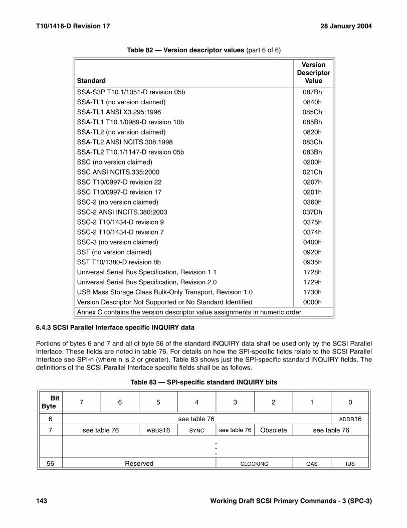
T10/1416-D Revision 17 28 January 2004
6.4.3 SCSI Parallel Interface specific INQUIRY data
Portions of bytes 6 and 7 and all of byte 56 of the standard INQUIRY data shall be used only by the SCSI ParallelInterface. These fields are noted in table 76. For details on how the SPI-specific fields relate to the SCSI ParallelInterface see SPI-n (where n is 2 or greater). Table 83 shows just the SPI-specific standard INQUIRY fields. Thedefinitions of the SCSI Parallel Interface specific fields shall be as follows.
SSA-S3P T10.1/1051-D revision 05b 087Bh
SSA-TL1 (no version claimed) 0840h
SSA-TL1 ANSI X3.295:1996 085Ch
SSA-TL1 T10.1/0989-D revision 10b 085Bh
SSA-TL2 (no version claimed) 0820h
SSA-TL2 ANSI NCITS.308:1998 083Ch
SSA-TL2 T10.1/1147-D revision 05b 083Bh
SSC (no version claimed) 0200h
SSC ANSI NCITS.335:2000 021Ch
SSC T10/0997-D revision 22 0207h
SSC T10/0997-D revision 17 0201h
SSC-2 (no version claimed) 0360h
SSC-2 ANSI INCITS.380:2003 037Dh
SSC-2 T10/1434-D revision 9 0375h
SSC-2 T10/1434-D revision 7 0374h
SSC-3 (no version claimed) 0400h
SST (no version claimed) 0920h
SST T10/1380-D revision 8b 0935h
Universal Serial Bus Specification, Revision 1.1 1728h
Universal Serial Bus Specification, Revision 2.0 1729h
USB Mass Storage Class Bulk-Only Transport, Revision 1.0 1730h
Version Descriptor Not Supported or No Standard Identified 0000h
Table 83 — SPI-specific standard INQUIRY bits
BitByte
7 6 5 4 3 2 1 0
6 see table 76 ADDR16
7 see table 76 WBUS16 SYNC see table 76 Obsolete see table 76
.
.
.
56 Reserved CLOCKING QAS IUS
Table 82 — Version descriptor values (part 6 of 6)
Standard
Version Descriptor
Value
Annex C contains the version descriptor value assignments in numeric order.
143 Working Draft SCSI Primary Commands - 3 (SPC-3)

28 January 2004 T10/1416-D Revision 17
A wide SCSI address 16 (ADDR16) bit of one indicates that the target supports 16-bit wide SCSI addresses. Avalue of zero indicates that the device does not support 16-bit wide SCSI addresses.
A wide bus 16 (WBUS16) bit of one indicates that the target supports 16-bit wide data transfers. A value of zeroindicates that the device does not support 16-bit wide data transfers.
A synchronous transfer (SYNC) bit of one indicates that the target supports synchronous data transfer. A value ofzero indicates the device does not support synchronous data transfer.
The obsolete bit 2 in byte 7 indicates whether the target supports an obsolete data transfers managementmechanism defined in SPI-2.
Table 84 defines the relationships between the ADDR16 and WBUS16 bits.
The CLOCKING field shall not apply to asynchronous transfers and is defined in table 85.
A quick arbitration and selection supported (QAS) bit of one indicates that the device server supports quickarbitration and selection. A value of zero indicates that the device server does not support quick arbitration andselection.
An information units supported (IUS) bit of one indicates that the device server supports information unit transfers.A value of zero indicates that the device server does not support information unit transfers.
NOTE 22 - The acronyms ST and DT and the terms 'quick arbitration and selection' and 'information units' aredefined in SPI-5.
6.4.4 Vital product data
The application client requests the vital product data information by setting the EVPD bit to one and specifying thepage code of the desired vital product data. See 7.6 for details about vital product data. The information returnedconsists of configuration data (e.g., vendor identification, product identification, model, serial number), manufac-turing data (e.g., plant and date of manufacture), field replaceable unit data and other vendor specific or devicespecific data. If the device server does not implement the requested page it shall return CHECK CONDITION
Table 84 — Maximum logical device configuration table
ADDR16 WBUS16 Description
0 0 8 bit wide data path on a single cable with 8 SCSI IDs supported
0 1 16 bit wide data path on a single cable with 8 SCSI IDs supported
1 1 16 bit wide data path on a single cable with 16 SCSI IDs supported
Table 85 — CLOCKING field
Code Description
00b Indicates the device server supports only ST
01b Indicates the device server supports only DT
10b Reserved
11b Indicates the device server supports ST and DT
Working Draft SCSI Primary Commands - 3 (SPC-3) 144

T10/1416-D Revision 17 28 January 2004
status. The a sense key shall be set to ILLEGAL REQUEST and the additional sense code shall be set to INVALIDFIELD IN CDB.
NOTES23 The device server should have the ability to process the INQUIRY command even when an error occurs that
prohibits normal command completion. In such a case, CHECK CONDITION status should be returned forcommands other than INQUIRY or REQUEST SENSE. The sense data returned may contain the fieldreplaceable unit code. The vital product data may be obtained for the failing device using the INQUIRYcommand.
24 This standard defines a format that allows device-independent application client software to display the vitalproduct data returned by the INQUIRY command. The contents of the data may be vendor specific, and maybe unusable without detailed information about the device.
25 This standard does not define the location or method of storing the vital product data. The retrieval of the datamay require completion of initialization operations within the device, that may induce delays before the data isavailable to the application client. Time-critical requirements are an implementation consideration and are notaddressed in this standard.
145 Working Draft SCSI Primary Commands - 3 (SPC-3)
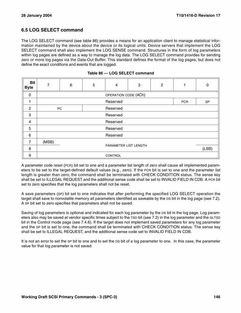
28 January 2004 T10/1416-D Revision 17
6.5 LOG SELECT command
The LOG SELECT command (see table 86) provides a means for an application client to manage statistical infor-mation maintained by the device about the device or its logical units. Device servers that implement the LOGSELECT command shall also implement the LOG SENSE command. Structures in the form of log parameterswithin log pages are defined as a way to manage the log data. The LOG SELECT command provides for sendingzero or more log pages via the Data-Out Buffer. This standard defines the format of the log pages, but does notdefine the exact conditions and events that are logged.
A parameter code reset (PCR) bit set to one and a parameter list length of zero shall cause all implemented param-eters to be set to the target-defined default values (e.g., zero). If the PCR bit is set to one and the parameter listlength is greater than zero, the command shall be terminated with CHECK CONDITION status. The sense keyshall be set to ILLEGAL REQUEST and the additional sense code shall be set to INVALID FIELD IN CDB. A PCR bitset to zero specifies that the log parameters shall not be reset.
A save parameters (SP) bit set to one indicates that after performing the specified LOG SELECT operation thetarget shall save to nonvolatile memory all parameters identified as saveable by the DS bit in the log page (see 7.2).A SP bit set to zero specifies that parameters shall not be saved.
Saving of log parameters is optional and indicated for each log parameter by the DS bit in the log page. Log param-eters also may be saved at vendor specific times subject to the TSD bit (see 7.2) in the log parameter and the GLTSD
bit in the Control mode page (see 7.4.6). If the target does not implement saved parameters for any log parameterand the SP bit is set to one, the command shall be terminated with CHECK CONDITION status. The sense keyshall be set to ILLEGAL REQUEST, and the additional sense code set to INVALID FIELD IN CDB.
It is not an error to set the SP bit to one and to set the DS bit of a log parameter to one. In this case, the parametervalue for that log parameter is not saved.
Table 86 — LOG SELECT command
BitByte
7 6 5 4 3 2 1 0
0 OPERATION CODE (4Ch)
1 Reserved PCR SP
2 PC Reserved
3 Reserved
4 Reserved
5 Reserved
6 Reserved
7 (MSB)PARAMETER LIST LENGTH
8 (LSB)
9 CONTROL
Working Draft SCSI Primary Commands - 3 (SPC-3) 146
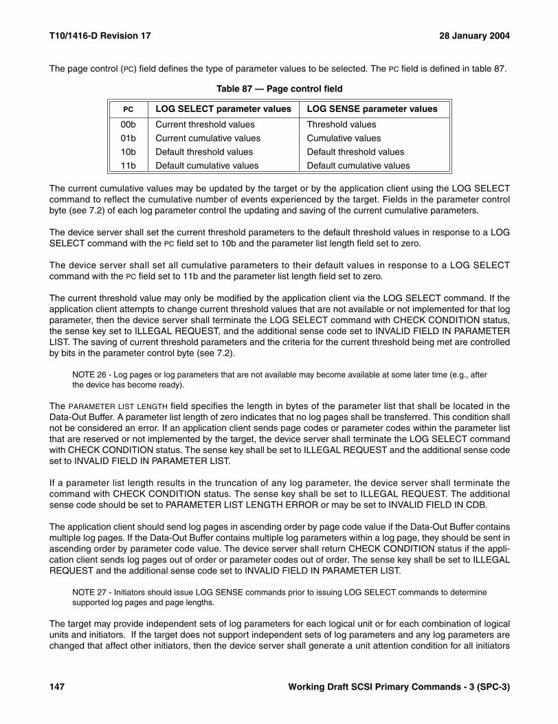
T10/1416-D Revision 17 28 January 2004
The page control (PC) field defines the type of parameter values to be selected. The PC field is defined in table 87.
The current cumulative values may be updated by the target or by the application client using the LOG SELECTcommand to reflect the cumulative number of events experienced by the target. Fields in the parameter controlbyte (see 7.2) of each log parameter control the updating and saving of the current cumulative parameters.
The device server shall set the current threshold parameters to the default threshold values in response to a LOGSELECT command with the PC field set to 10b and the parameter list length field set to zero.
The device server shall set all cumulative parameters to their default values in response to a LOG SELECTcommand with the PC field set to 11b and the parameter list length field set to zero.
The current threshold value may only be modified by the application client via the LOG SELECT command. If theapplication client attempts to change current threshold values that are not available or not implemented for that logparameter, then the device server shall terminate the LOG SELECT command with CHECK CONDITION status,the sense key set to ILLEGAL REQUEST, and the additional sense code set to INVALID FIELD IN PARAMETERLIST. The saving of current threshold parameters and the criteria for the current threshold being met are controlledby bits in the parameter control byte (see 7.2).
NOTE 26 - Log pages or log parameters that are not available may become available at some later time (e.g., afterthe device has become ready).
The PARAMETER LIST LENGTH field specifies the length in bytes of the parameter list that shall be located in theData-Out Buffer. A parameter list length of zero indicates that no log pages shall be transferred. This condition shallnot be considered an error. If an application client sends page codes or parameter codes within the parameter listthat are reserved or not implemented by the target, the device server shall terminate the LOG SELECT commandwith CHECK CONDITION status. The sense key shall be set to ILLEGAL REQUEST and the additional sense codeset to INVALID FIELD IN PARAMETER LIST.
If a parameter list length results in the truncation of any log parameter, the device server shall terminate thecommand with CHECK CONDITION status. The sense key shall be set to ILLEGAL REQUEST. The additionalsense code should be set to PARAMETER LIST LENGTH ERROR or may be set to INVALID FIELD IN CDB.
The application client should send log pages in ascending order by page code value if the Data-Out Buffer containsmultiple log pages. If the Data-Out Buffer contains multiple log parameters within a log page, they should be sent inascending order by parameter code value. The device server shall return CHECK CONDITION status if the appli-cation client sends log pages out of order or parameter codes out of order. The sense key shall be set to ILLEGALREQUEST and the additional sense code set to INVALID FIELD IN PARAMETER LIST.
NOTE 27 - Initiators should issue LOG SENSE commands prior to issuing LOG SELECT commands to determinesupported log pages and page lengths.
The target may provide independent sets of log parameters for each logical unit or for each combination of logicalunits and initiators. If the target does not support independent sets of log parameters and any log parameters arechanged that affect other initiators, then the device server shall generate a unit attention condition for all initiators
Table 87 — Page control field
PC LOG SELECT parameter values LOG SENSE parameter values
00b Current threshold values Threshold values
01b Current cumulative values Cumulative values
10b Default threshold values Default threshold values
11b Default cumulative values Default cumulative values
147 Working Draft SCSI Primary Commands - 3 (SPC-3)
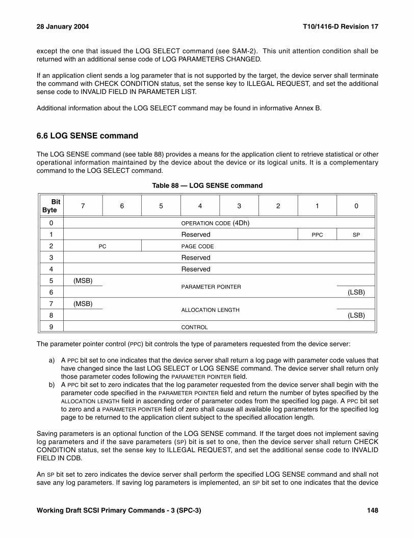
28 January 2004 T10/1416-D Revision 17
except the one that issued the LOG SELECT command (see SAM-2). This unit attention condition shall bereturned with an additional sense code of LOG PARAMETERS CHANGED.
If an application client sends a log parameter that is not supported by the target, the device server shall terminatethe command with CHECK CONDITION status, set the sense key to ILLEGAL REQUEST, and set the additionalsense code to INVALID FIELD IN PARAMETER LIST.
Additional information about the LOG SELECT command may be found in informative Annex B.
6.6 LOG SENSE command
The LOG SENSE command (see table 88) provides a means for the application client to retrieve statistical or otheroperational information maintained by the device about the device or its logical units. It is a complementarycommand to the LOG SELECT command.
The parameter pointer control (PPC) bit controls the type of parameters requested from the device server:
a) A PPC bit set to one indicates that the device server shall return a log page with parameter code values thathave changed since the last LOG SELECT or LOG SENSE command. The device server shall return onlythose parameter codes following the PARAMETER POINTER field.
b) A PPC bit set to zero indicates that the log parameter requested from the device server shall begin with theparameter code specified in the PARAMETER POINTER field and return the number of bytes specified by theALLOCATION LENGTH field in ascending order of parameter codes from the specified log page. A PPC bit setto zero and a PARAMETER POINTER field of zero shall cause all available log parameters for the specified logpage to be returned to the application client subject to the specified allocation length.
Saving parameters is an optional function of the LOG SENSE command. If the target does not implement savinglog parameters and if the save parameters (SP) bit is set to one, then the device server shall return CHECKCONDITION status, set the sense key to ILLEGAL REQUEST, and set the additional sense code to INVALIDFIELD IN CDB.
An SP bit set to zero indicates the device server shall perform the specified LOG SENSE command and shall notsave any log parameters. If saving log parameters is implemented, an SP bit set to one indicates that the device
Table 88 — LOG SENSE command
BitByte
7 6 5 4 3 2 1 0
0 OPERATION CODE (4Dh)
1 Reserved PPC SP
2 PC PAGE CODE
3 Reserved
4 Reserved
5 (MSB)PARAMETER POINTER
6 (LSB)
7 (MSB)ALLOCATION LENGTH
8 (LSB)
9 CONTROL
Working Draft SCSI Primary Commands - 3 (SPC-3) 148
T10/1416-D Revision 17 28 January 2004
server shall perform the specified LOG SENSE command and shall save all log parameters identified as saveableby the DS bit (see 7.2) to a nonvolatile, vendor specific location.
The page control (PC) field defines the type of parameter values to be selected (see 6.5 for the definition of thepage control field). The parameter values returned by a LOG SENSE command are determined as follows:
a) The specified parameter values at the last update (i.e., in response to a LOG SELECT or LOG SENSEcommand or done automatically by the target for cumulative values);
b) The saved values, if saved parameters are implemented and an update has not occurred since the lastlogical unit reset; or
c) The default values, if saved values are not available or not implemented and an update has not occurredsince the last logical unit reset.
The PAGE CODE field identifies which log page of data is being requested (see 7.2). If the log page code is reservedor not implemented, the device server shall terminate the command with CHECK CONDITION status. The sensekey shall be set to ILLEGAL REQUEST with the additional sense code set to INVALID FIELD IN CDB.
The PARAMETER POINTER field allows the application client to request parameter data beginning from a specificparameter code to the maximum allocation length or the maximum parameter code supported by the target,whichever is less. If the value of the PARAMETER POINTER field is larger than the largest available parameter codeknown to the device server for the specified log page, the device server shall terminate the command with CHECKCONDITION status. The sense key shall be set to ILLEGAL REQUEST and the additional sense code shall be setto INVALID FIELD IN CDB.
Log parameters within the specified log page shall be transferred in ascending order according to parameter code.
Additional information about the LOG SENSE command may be found in Annex B.
149 Working Draft SCSI Primary Commands - 3 (SPC-3)
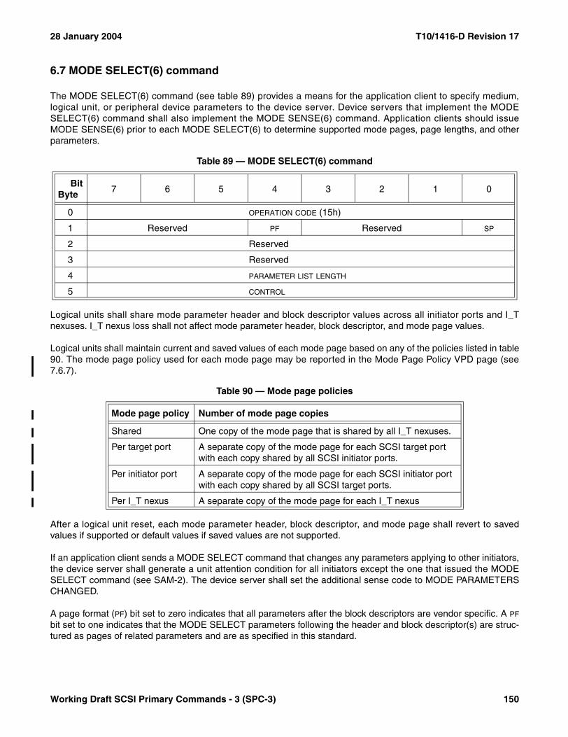
28 January 2004 T10/1416-D Revision 17
6.7 MODE SELECT(6) command
The MODE SELECT(6) command (see table 89) provides a means for the application client to specify medium,logical unit, or peripheral device parameters to the device server. Device servers that implement the MODESELECT(6) command shall also implement the MODE SENSE(6) command. Application clients should issueMODE SENSE(6) prior to each MODE SELECT(6) to determine supported mode pages, page lengths, and otherparameters.
Logical units shall share mode parameter header and block descriptor values across all initiator ports and I_Tnexuses. I_T nexus loss shall not affect mode parameter header, block descriptor, and mode page values.
Logical units shall maintain current and saved values of each mode page based on any of the policies listed in table90. The mode page policy used for each mode page may be reported in the Mode Page Policy VPD page (see7.6.7).
After a logical unit reset, each mode parameter header, block descriptor, and mode page shall revert to savedvalues if supported or default values if saved values are not supported.
If an application client sends a MODE SELECT command that changes any parameters applying to other initiators,the device server shall generate a unit attention condition for all initiators except the one that issued the MODESELECT command (see SAM-2). The device server shall set the additional sense code to MODE PARAMETERSCHANGED.
A page format (PF) bit set to zero indicates that all parameters after the block descriptors are vendor specific. A PF
bit set to one indicates that the MODE SELECT parameters following the header and block descriptor(s) are struc-tured as pages of related parameters and are as specified in this standard.
Table 89 — MODE SELECT(6) command
BitByte
7 6 5 4 3 2 1 0
0 OPERATION CODE (15h)
1 Reserved PF Reserved SP
2 Reserved
3 Reserved
4 PARAMETER LIST LENGTH
5 CONTROL
Table 90 — Mode page policies
Mode page policy Number of mode page copies
Shared One copy of the mode page that is shared by all I_T nexuses.
Per target port A separate copy of the mode page for each SCSI target port with each copy shared by all SCSI initiator ports.
Per initiator port A separate copy of the mode page for each SCSI initiator port with each copy shared by all SCSI target ports.
Per I_T nexus A separate copy of the mode page for each I_T nexus
Working Draft SCSI Primary Commands - 3 (SPC-3) 150
T10/1416-D Revision 17 28 January 2004
A save pages (SP) bit set to zero indicates the device server shall perform the specified MODE SELECT operation,and shall not save any mode pages. If the logical unit implements no distinction between current and saved modepages and the SP bit is set to zero, the command shall be terminated with CHECK CONDITION status. The sensekey shall be set to ILLEGAL REQUEST, and the additional sense code shall be set to INVALID FIELD IN CDB. AnSP bit set to one indicates that the device server shall perform the specified MODE SELECT operation, and shallsave to a nonvolatile vendor specific location all the saveable mode pages including any sent in the Data-OutBuffer. The SP bit is optional. Mode pages that are saved are identified by the parameter saveable (PS) bit that isreturned in the page header by the MODE SENSE command (see 7.4). If the PS bit is set to one in the MODESENSE data then the mode page shall be saveable by issuing a MODE SELECT command with the SP bit set toone. If the logical unit does not implement saved mode pages and the SP bit is set to one, the command shall beterminated with CHECK CONDITION status. The sense key shall be set to ILLEGAL REQUEST, and the additionalsense code shall be set to INVALID FIELD IN CDB.
The PARAMETER LIST LENGTH field specifies the length in bytes of the mode parameter list that shall be contained inthe Data-Out Buffer. A parameter list length of zero indicates that the Data-Out Buffer shall be empty. Thiscondition shall not be considered as an error.
The device server shall terminate the command with CHECK CONDITION status if the parameter list length resultsin the truncation of any mode parameter header, mode parameter block descriptor(s), or mode page. The sensekey shall be set to ILLEGAL REQUEST, and the additional sense code shall be set to PARAMETER LIST LENGTHERROR.
The mode parameter list for the MODE SELECT and MODE SENSE commands is defined in 7.4. Parts of eachmode parameter list are defined in a device-type dependent manner. Definitions for the parts of each modeparameter list that are uniquely for each device-type may be found in the applicable command standards (see3.1.17).
The device server shall terminate the MODE SELECT command with CHECK CONDITION status, set the sensekey to ILLEGAL REQUEST, set the additional sense code to INVALID FIELD IN PARAMETER LIST, and shall notchange any mode parameters for the following conditions:
a) If the application client sets any field that is reported as not changeable by the device server to a valueother than its current value;
b) If the application client sets any field in the mode parameter header or block descriptor(s) to an unsup-ported value;
c) If an application client sends a mode page with a page length not equal to the page length returned by theMODE SENSE command for that mode page;
d) If the application client sends a unsupported value for a mode parameter and rounding is not implementedfor that mode parameter; or
e) If the application client sets any reserved field in the mode parameter list to a non-zero value.
If the application client sends a value for a mode parameter that is outside the range supported by the deviceserver and rounding is implemented for that mode parameter, the device server handles the condition by either:
a) Rounding the parameter to an acceptable value and terminate the command as described in 5.4; orb) Terminating the command with CHECK CONDITION status, the sense key set to ILLEGAL REQUEST, and
set the additional sense code to INVALID FIELD IN PARAMETER LIST.
A device server may alter any mode parameter in any mode page, even those reported as non-changeable, as aresult of changes to other mode parameters.
The device server validates the non-changeable mode parameters against the current values that existed for thosemode parameters prior to the MODE SELECT command.
151 Working Draft SCSI Primary Commands - 3 (SPC-3)

28 January 2004 T10/1416-D Revision 17
NOTE 28 - The current values calculated by the device server may affect the application client's operation. Theapplication client may issue a MODE SENSE command after each MODE SELECT command, to determine thecurrent values.
6.8 MODE SELECT(10) command
The MODE SELECT(10) command (see table 91) provides a means for the application client to specify medium,logical unit, or peripheral device parameters to the device server. See the MODE SELECT(6) command (6.7) for adescription of the fields and operation of this command. Application clients should issue MODE SENSE(10) prior toeach MODE SELECT(10) to determine supported mode pages, page lengths, and other parameters. Deviceservers that implement the MODE SELECT(10) command shall also implement the MODE SENSE(10) command.
6.9 MODE SENSE(6) command
6.9.1 MODE SENSE(6) command introduction
The MODE SENSE(6) command (see table 92) provides a means for a device server to report parameters to anapplication client. It is a complementary command to the MODE SELECT(6) command. Device servers thatimplement the MODE SENSE(6) command shall also implement the MODE SELECT(6) command.
A disable block descriptors (DBD) bit set to zero indicates that the device server may return zero or more blockdescriptors in the returned MODE SENSE data (see 7.4). A DBD bit set to one specifies that the device server shallnot return any block descriptors in the returned MODE SENSE data.
Table 91 — MODE SELECT(10) command
BitByte
7 6 5 4 3 2 1 0
0 OPERATION CODE (55h)
1 Reserved PF Reserved SP
2 Reserved
3 Reserved
4 Reserved
5 Reserved
6 Reserved
7 (MSB)PARAMETER LIST LENGTH
8 (LSB)
9 CONTROL
Working Draft SCSI Primary Commands - 3 (SPC-3) 152
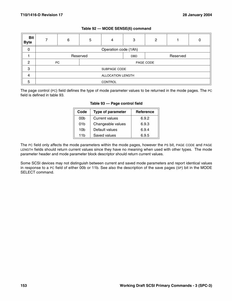
T10/1416-D Revision 17 28 January 2004
The page control (PC) field defines the type of mode parameter values to be returned in the mode pages. The PC
field is defined in table 93.
The PC field only affects the mode parameters within the mode pages, however the PS bit, PAGE CODE and PAGE
LENGTH fields should return current values since they have no meaning when used with other types. The modeparameter header and mode parameter block descriptor should return current values.
Some SCSI devices may not distinguish between current and saved mode parameters and report identical valuesin response to a PC field of either 00b or 11b. See also the description of the save pages (SP) bit in the MODESELECT command.
Table 92 — MODE SENSE(6) command
BitByte
7 6 5 4 3 2 1 0
0 Operation code (1Ah)
1 Reserved DBD Reserved
2 PC PAGE CODE
3 SUBPAGE CODE
4 ALLOCATION LENGTH
5 CONTROL
Table 93 — Page control field
Code Type of parameter Reference
00b Current values 6.9.2
01b Changeable values 6.9.3
10b Default values 6.9.4
11b Saved values 6.9.5
153 Working Draft SCSI Primary Commands - 3 (SPC-3)
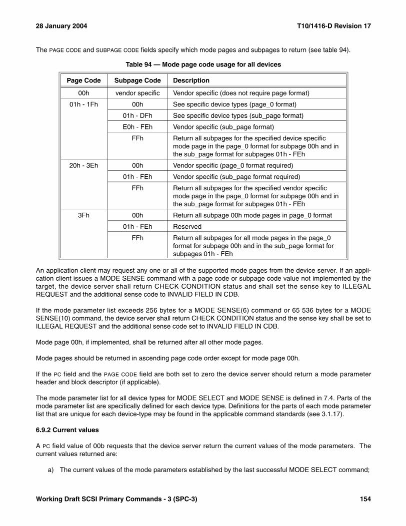
28 January 2004 T10/1416-D Revision 17
The PAGE CODE and SUBPAGE CODE fields specify which mode pages and subpages to return (see table 94).
An application client may request any one or all of the supported mode pages from the device server. If an appli-cation client issues a MODE SENSE command with a page code or subpage code value not implemented by thetarget, the device server shall return CHECK CONDITION status and shall set the sense key to ILLEGALREQUEST and the additional sense code to INVALID FIELD IN CDB.
If the mode parameter list exceeds 256 bytes for a MODE SENSE(6) command or 65 536 bytes for a MODESENSE(10) command, the device server shall return CHECK CONDITION status and the sense key shall be set toILLEGAL REQUEST and the additional sense code set to INVALID FIELD IN CDB.
Mode page 00h, if implemented, shall be returned after all other mode pages.
Mode pages should be returned in ascending page code order except for mode page 00h.
If the PC field and the PAGE CODE field are both set to zero the device server should return a mode parameterheader and block descriptor (if applicable).
The mode parameter list for all device types for MODE SELECT and MODE SENSE is defined in 7.4. Parts of themode parameter list are specifically defined for each device type. Definitions for the parts of each mode parameterlist that are unique for each device-type may be found in the applicable command standards (see 3.1.17).
6.9.2 Current values
A PC field value of 00b requests that the device server return the current values of the mode parameters. Thecurrent values returned are:
a) The current values of the mode parameters established by the last successful MODE SELECT command;
Table 94 — Mode page code usage for all devices
Page Code Subpage Code Description
00h vendor specific Vendor specific (does not require page format)
01h - 1Fh 00h See specific device types (page_0 format)
01h - DFh See specific device types (sub_page format)
E0h - FEh Vendor specific (sub_page format)
FFh Return all subpages for the specified device specific mode page in the page_0 format for subpage 00h and in the sub_page format for subpages 01h - FEh
20h - 3Eh 00h Vendor specific (page_0 format required)
01h - FEh Vendor specific (sub_page format required)
FFh Return all subpages for the specified vendor specific mode page in the page_0 format for subpage 00h and in the sub_page format for subpages 01h - FEh
3Fh 00h Return all subpage 00h mode pages in page_0 format
01h - FEh Reserved
FFh Return all subpages for all mode pages in the page_0 format for subpage 00h and in the sub_page format for subpages 01h - FEh
Working Draft SCSI Primary Commands - 3 (SPC-3) 154
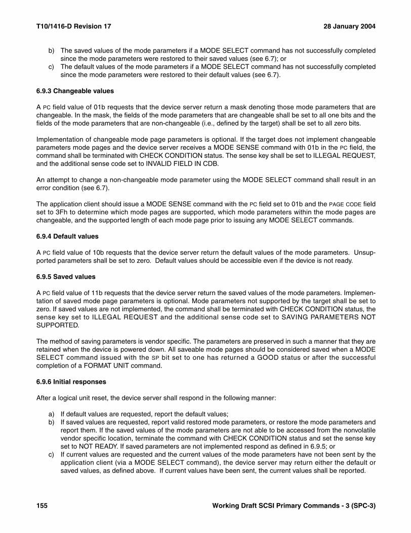
T10/1416-D Revision 17 28 January 2004
b) The saved values of the mode parameters if a MODE SELECT command has not successfully completedsince the mode parameters were restored to their saved values (see 6.7); or
c) The default values of the mode parameters if a MODE SELECT command has not successfully completedsince the mode parameters were restored to their default values (see 6.7).
6.9.3 Changeable values
A PC field value of 01b requests that the device server return a mask denoting those mode parameters that arechangeable. In the mask, the fields of the mode parameters that are changeable shall be set to all one bits and thefields of the mode parameters that are non-changeable (i.e., defined by the target) shall be set to all zero bits.
Implementation of changeable mode page parameters is optional. If the target does not implement changeableparameters mode pages and the device server receives a MODE SENSE command with 01b in the PC field, thecommand shall be terminated with CHECK CONDITION status. The sense key shall be set to ILLEGAL REQUEST,and the additional sense code set to INVALID FIELD IN CDB.
An attempt to change a non-changeable mode parameter using the MODE SELECT command shall result in anerror condition (see 6.7).
The application client should issue a MODE SENSE command with the PC field set to 01b and the PAGE CODE fieldset to 3Fh to determine which mode pages are supported, which mode parameters within the mode pages arechangeable, and the supported length of each mode page prior to issuing any MODE SELECT commands.
6.9.4 Default values
A PC field value of 10b requests that the device server return the default values of the mode parameters. Unsup-ported parameters shall be set to zero. Default values should be accessible even if the device is not ready.
6.9.5 Saved values
A PC field value of 11b requests that the device server return the saved values of the mode parameters. Implemen-tation of saved mode page parameters is optional. Mode parameters not supported by the target shall be set tozero. If saved values are not implemented, the command shall be terminated with CHECK CONDITION status, thesense key set to ILLEGAL REQUEST and the additional sense code set to SAVING PARAMETERS NOTSUPPORTED.
The method of saving parameters is vendor specific. The parameters are preserved in such a manner that they areretained when the device is powered down. All saveable mode pages should be considered saved when a MODESELECT command issued with the SP bit set to one has returned a GOOD status or after the successfulcompletion of a FORMAT UNIT command.
6.9.6 Initial responses
After a logical unit reset, the device server shall respond in the following manner:
a) If default values are requested, report the default values;b) If saved values are requested, report valid restored mode parameters, or restore the mode parameters and
report them. If the saved values of the mode parameters are not able to be accessed from the nonvolatilevendor specific location, terminate the command with CHECK CONDITION status and set the sense keyset to NOT READY. If saved parameters are not implemented respond as defined in 6.9.5; or
c) If current values are requested and the current values of the mode parameters have not been sent by theapplication client (via a MODE SELECT command), the device server may return either the default orsaved values, as defined above. If current values have been sent, the current values shall be reported.
155 Working Draft SCSI Primary Commands - 3 (SPC-3)

28 January 2004 T10/1416-D Revision 17
6.10 MODE SENSE(10) command
The MODE SENSE(10) command (see table 95) provides a means for a device server to report parameters to anapplication client. It is a complementary command to the MODE SELECT(10) command. Device servers thatimplement the MODE SENSE(10) command shall also implement the MODE SELECT(10) command.
If the Long LBA Accepted (LLBAA) bit is set to one, the device server is allowed to return parameter data with theLONGLBA bit equal to one (see 7.4.3). If LLBAA bit is set to zero, the LONGLBA bit shall be zero in the parameter datareturned by the device server.
See the MODE SENSE(6) command (6.9) for a description of the other fields and operation of this command.
Table 95 — MODE SENSE(10) command
BitByte
7 6 5 4 3 2 1 0
0 OPERATION CODE (5Ah)
1 Reserved LLBAA DBD Reserved
2 PC PAGE CODE
3 SUBPAGE CODE
4 Reserved
5 Reserved
6 Reserved
7 (MSB)ALLOCATION LENGTH
8 (LSB)
9 CONTROL
Working Draft SCSI Primary Commands - 3 (SPC-3) 156

T10/1416-D Revision 17 28 January 2004
6.11 PERSISTENT RESERVE IN command
6.11.1 PERSISTENT RESERVE IN command introduction
The PERSISTENT RESERVE IN command (see table 96) is used to obtain information about persistent reserva-tions and reservation keys (i.e., registrations) that are active within a device server. This command is used inconjunction with the PERSISTENT RESERVE OUT command (see 6.12).
The PERSISTENT RESERVE IN parameter data includes a field that indicates the number of parameter data bytesavailable to be returned. The ALLOCATION LENGTH field in the CDB indicates how much space has been allocatedfor the returned parameter list. An allocation length that is not sufficient to contain the entire parameter list shall notbe considered an error. If the complete list is required, the application client should send a new PERSISTENTRESERVE IN command with allocation length large enough to contain the entire list.
6.11.2 PERSISTENT RESERVE IN service actions
6.11.2.1 Summary of PERSISTENT RESERVE IN service actions
The service action codes for the PERSISTENT RESERVE IN command are defined in table 97.
Table 96 — PERSISTENT RESERVE IN command
BitByte
7 6 5 4 3 2 1 0
0 OPERATION CODE (5Eh)
1 Reserved SERVICE ACTION
2 Reserved
3 Reserved
4 Reserved
5 Reserved
6 Reserved
7 (MSB)ALLOCATION LENGTH
8 (LSB)
9 CONTROL
Table 97 — PERSISTENT RESERVE IN service action codes
Code Name Description References
00h READ KEYS Reads all registered reservation keys (i.e., registrations) as described in 5.6.4.2
6.11.2.26.11.3
01h READ RESERVATION Reads the current persistent reservations as described in 5.6.4.3
6.11.2.36.11.4
02h REPORT CAPABILITIES Returns capability information 6.11.2.46.11.5
03h - 1Fh Reserved Reserved
157 Working Draft SCSI Primary Commands - 3 (SPC-3)

28 January 2004 T10/1416-D Revision 17
6.11.2.2 READ KEYS
The READ KEYS service action requests that the device server return a parameter list containing a header and alist of each currently registered I_T nexus’ reservation key. If multiple I_T nexuses have registered with the samekey, then that key value shall be listed multiple times, once for each such registration.
For more information on READ KEYS see 5.6.4.2.
6.11.2.3 READ RESERVATION
The READ RESERVATION service action requests that the device server return a parameter list containing aheader and the persistent reservation, if any, that is present in the device server.
For more information on READ RESERVATION see 5.6.4.3.
6.11.2.4 REPORT CAPABILITIES
The REPORT CAPABILITIES service action requests that the device server return information on persistent reser-vation features.
6.11.3 PERSISTENT RESERVE IN parameter data for READ KEYS
The format for the parameter data provided in response to a PERSISTENT RESERVE IN command with the READKEYS service action is shown in table 98.
The Persistent Reservations Generation (PRGENERATION) field shall contain a 32-bit counter maintained by thedevice server that shall be incremented every time a PERSISTENT RESERVE OUT command requests aREGISTER, a REGISTER AND IGNORE EXISTING KEY, a CLEAR, a PREEMPT, or a PREEMPT AND ABORTservice action. The counter shall not be incremented by a PERSISTENT RESERVE IN command, by aPERSISTENT RESERVE OUT command that performs a RESERVE or RELEASE service action, or by aPERSISTENT RESERVE OUT command that is terminated due to an error or reservation conflict. Regardless ofthe APTPL bit value the PRgeneration value shall be set to zero by a power on.
Table 98 — PERSISTENT RESERVE IN parameter data for READ KEYS
BitByte
7 6 5 4 3 2 1 0
0 (MSB)PRGENERATION
3 (LSB)
4 (MSB)ADDITIONAL LENGTH (n-7)
7 (LSB)
Reservation key list
8 (MSB)First reservation key
15 (LSB)...
n-7 (MSB)Last reservation key
n (LSB)
Working Draft SCSI Primary Commands - 3 (SPC-3) 158

T10/1416-D Revision 17 28 January 2004
The ADDITIONAL LENGTH field contains a count of the number of bytes in the Reservation key list. If the allocationlength specified by the PERSISTENT RESERVE IN command is not sufficient to contain the entire parameter list,then only the first portion of the list (byte 0 to the allocation length) shall be sent to the application client. The incre-mental remaining bytes shall be truncated, although the ADDITIONAL LENGTH field shall still contain the actualnumber of bytes in the reservation key list without consideration of any truncation resulting from an insufficientallocation length. This shall not be considered an error.
The reservation key list contains the 8-byte reservation keys for all I_T nexuses that have registered with the deviceserver through all combinations of initiator ports and target ports.
6.11.4 PERSISTENT RESERVE IN parameter data for READ RESERVATION
6.11.4.1 Format of PERSISTENT RESERVE IN parameter data for READ RESERVATION
When no persistent reservation is held, the format for the parameter data provided in response to a PERSISTENTRESERVE IN command with the READ RESERVATION service action is shown in table 99.
The PRGENERATION field shall be as defined for the PERSISTENT RESERVE IN READ KEYS parameter data (see6.11.3).
The ADDITIONAL LENGTH field hall be set to zero, indicating that no persistent reservation is held.
Table 99 — PERSISTENT RESERVE IN parameter data for READ RESERVATION with no reservation held
BitByte
7 6 5 4 3 2 1 0
0 (MSB)PRGENERATION
3 (LSB)
4 (MSB)ADDITIONAL LENGTH (0)
7 (LSB)
159 Working Draft SCSI Primary Commands - 3 (SPC-3)

28 January 2004 T10/1416-D Revision 17
When a persistent reservation is held, the format for the parameter data provided in response to a PERSISTENTRESERVE IN command with the READ RESERVATION service action is shown in table 100.
The PRGENERATION field shall be as defined for the PERSISTENT RESERVE IN READ KEYS parameter data.
The ADDITIONAL LENGTH field contains a count of the number of bytes to follow and shall be set to 16. If theallocation length specified by the PERSISTENT RESERVE IN command is not sufficient to contain the entireparameter list, then only the first portion of the list (byte 0 to the allocation length) shall be sent to the applicationclient. The incremental remaining bytes shall be truncated, although the ADDITIONAL LENGTH field shall still contain16. This shall not be considered an error.
The RESERVATION KEY field shall contain the reservation key under which the persistent reservation is held (see5.6.7).
The SCOPE field shall be set to LU_SCOPE (see 6.11.4.2).
The TYPE field shall contain the persistent reservation type (see 6.11.4.3) specified in the PERSISTENT RESERVEOUT command that created the persistent reservation.
The obsolete fields in bytes 16 through 19, byte 14 and byte 15 were defined in a previous standard.
Table 100 — PERSISTENT RESERVE IN parameter data for READ RESERVATION with reservation
BitByte
7 6 5 4 3 2 1 0
0 (MSB)PRGENERATION
3 (LSB)
4 (MSB)ADDITIONAL LENGTH (10h)
7 (LSB)
8 (MSB)RESERVATION KEY
15 (LSB)
16Obsolete
19
20 Reserved
21 SCOPE TYPE
22Obsolete
23
Working Draft SCSI Primary Commands - 3 (SPC-3) 160

T10/1416-D Revision 17 28 January 2004
6.11.4.2 Persistent reservations Scope
The value in the SCOPE field shall be LU_SCOPE (see table 101), indicating that the persistent reservation appliesto the entire logical unit.
The LU_SCOPE scope shall be implemented by all device servers that implement PERSISTENT RESERVE OUT.
6.11.4.3 Persistent Reservations Type
The value in the TYPE field shall specify the characteristics of the persistent reservation being established for alllogical blocks within the element or within the logical unit. Table 102 defines the characteristics of the different typevalues. For each persistent reservation type, table 102 lists code value and describes the required device serversupport. In table 102, the description of required device server support is divided into three paragraphs:
1) A definition of the required handling for read operations;2) A definition of the required handling for write operations; and3) A definition of the persistent reservation holder (see 5.6.7).
Table 101 — Persistent reservation scope codes
Code Name Description
0h LU_SCOPE Persistent reservation applies to the full logical unit
1h - 2h Obsolete
3h - Fh Reserved
Table 102 — Persistent reservation type codes (part 1 of 2)
Code Name Description
0h Obsolete
1h WriteExclusive
Reads Shared: Any application client on any I_T nexus may initiate tasks that request transfers from the storage medium or cache of the logical unit to the I_T nexus.Writes Exclusive: Any task from any I_T nexus other than the I_T nexus holding the persistent reservation that requests a transfer from the I_T nexus to the storage medium or cache of the logical unit shall be terminated with RESERVATION CONFLICT status.Persistent Reservation Holder: The I_T nexus that delivered the PERSISTENT RESERVE OUT command with RESERVE, PREEMPT, or PREEMPT AND ABORT service action as identified by its registered reservation key.
2h Obsolete
3h ExclusiveAccess
Reads Exclusive: Any task from any I_T nexus other than the I_T nexus holding the persistent reservation that requests a transfer from the storage medium or cache of the logical unit to the I_T nexus shall be terminated with RESERVATION CONFLICT status.Writes Exclusive: Any task from any I_T nexus other than the I_T nexus holding the persistent reservation that requests a transfer from the I_T nexus to the storage medium or cache of the logical unit shall be terminated with RESERVATION CONFLICT status.Persistent Reservation Holder: The I_T nexus that delivered the PERSISTENT RESERVE OUT command with RESERVE, PREEMPT, or PREEMPT AND ABORT service action as identified by its registered reservation key.
161 Working Draft SCSI Primary Commands - 3 (SPC-3)
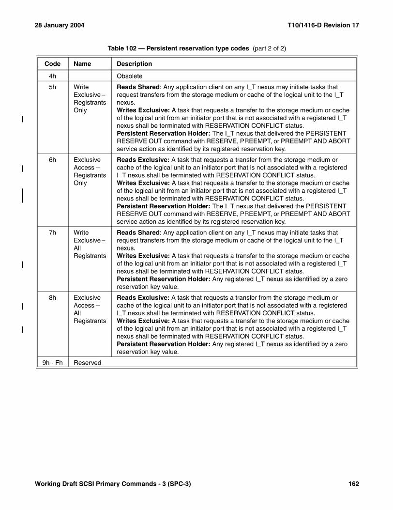
28 January 2004 T10/1416-D Revision 17
4h Obsolete
5h Write Exclusive – RegistrantsOnly
Reads Shared: Any application client on any I_T nexus may initiate tasks that request transfers from the storage medium or cache of the logical unit to the I_T nexus.Writes Exclusive: A task that requests a transfer to the storage medium or cache of the logical unit from an initiator port that is not associated with a registered I_T nexus shall be terminated with RESERVATION CONFLICT status.Persistent Reservation Holder: The I_T nexus that delivered the PERSISTENT RESERVE OUT command with RESERVE, PREEMPT, or PREEMPT AND ABORT service action as identified by its registered reservation key.
6h Exclusive Access – RegistrantsOnly
Reads Exclusive: A task that requests a transfer from the storage medium or cache of the logical unit to an initiator port that is not associated with a registered I_T nexus shall be terminated with RESERVATION CONFLICT status.Writes Exclusive: A task that requests a transfer to the storage medium or cache of the logical unit from an initiator port that is not associated with a registered I_T nexus shall be terminated with RESERVATION CONFLICT status.Persistent Reservation Holder: The I_T nexus that delivered the PERSISTENT RESERVE OUT command with RESERVE, PREEMPT, or PREEMPT AND ABORT service action as identified by its registered reservation key.
7h Write Exclusive – AllRegistrants
Reads Shared: Any application client on any I_T nexus may initiate tasks that request transfers from the storage medium or cache of the logical unit to the I_T nexus.Writes Exclusive: A task that requests a transfer to the storage medium or cache of the logical unit from an initiator port that is not associated with a registered I_T nexus shall be terminated with RESERVATION CONFLICT status.Persistent Reservation Holder: Any registered I_T nexus as identified by a zero reservation key value.
8h Exclusive Access – AllRegistrants
Reads Exclusive: A task that requests a transfer from the storage medium or cache of the logical unit to an initiator port that is not associated with a registered I_T nexus shall be terminated with RESERVATION CONFLICT status.Writes Exclusive: A task that requests a transfer to the storage medium or cache of the logical unit from an initiator port that is not associated with a registered I_T nexus shall be terminated with RESERVATION CONFLICT status.Persistent Reservation Holder: Any registered I_T nexus as identified by a zero reservation key value.
9h - Fh Reserved
Table 102 — Persistent reservation type codes (part 2 of 2)
Code Name Description
Working Draft SCSI Primary Commands - 3 (SPC-3) 162
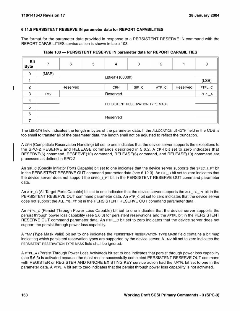
T10/1416-D Revision 17 28 January 2004
6.11.5 PERSISTENT RESERVE IN parameter data for REPORT CAPABILITIES
The format for the parameter data provided in response to a PERSISTENT RESERVE IN command with theREPORT CAPABILITIES service action is shown in table 103.
The LENGTH field indicates the length in bytes of the parameter data. If the ALLOCATION LENGTH field in the CDB istoo small to transfer all of the parameter data, the length shall not be adjusted to reflect the truncation.
A CRH (Compatible Reservation Handling) bit set to one indicates that the device server supports the exceptions tothe SPC-2 RESERVE and RELEASE commands described in 5.6.2. A CRH bit set to zero indicates thatRESERVE(6) command, RESERVE(10) command, RELEASE(6) command, and RELEASE(10) command areprocessed as defined in SPC-2.
An SIP_C (Specify Initiator Ports Capable) bit set to one indicates that the device server supports the SPEC_I_PT bitin the PERSISTENT RESERVE OUT command parameter data (see 6.12.3). An SIP_C bit set to zero indicates thatthe device server does not support the SPEC_I_PT bit in the PERSISTENT RESERVE OUT command parameterdata.
An ATP_C (All Target Ports Capable) bit set to one indicates that the device server supports the ALL_TG_PT bit in thePERSISTENT RESERVE OUT command parameter data. An ATP_C bit set to zero indicates that the device serverdoes not support the ALL_TG_PT bit in the PERSISTENT RESERVE OUT command parameter data.
An PTPL_C (Persist Through Power Loss Capable) bit set to one indicates that the device server supports thepersist through power loss capability (see 5.6.3) for persistent reservations and the APTPL bit in the PERSISTENTRESERVE OUT command parameter data. An PTPL_C bit set to zero indicates that the device server does notsupport the persist through power loss capability.
A TMV (Type Mask Valid) bit set to one indicates the PERSISTENT RESERVATION TYPE MASK field contains a bit mapindicating which persistent reservation types are supported by the device server. A TMV bit set to zero indicates thePERSISTENT RESERVATION TYPE MASK field shall be ignored.
A PTPL_A (Persist Through Power Loss Activated) bit set to one indicates that persist through power loss capability(see 5.6.3) is activated because the most recent successfully completed PERSISTENT RESERVE OUT commandwith REGISTER or REGISTER AND IGNORE EXISTING KEY service action had the APTPL bit set to one in theparameter data. A PTPL_A bit set to zero indicates that the persist through power loss capability is not activated.
Table 103 — PERSISTENT RESERVE IN parameter data for REPORT CAPABILITIES
BitByte
7 6 5 4 3 2 1 0
0 (MSB)LENGTH (0008h)
1 (LSB)
2 Reserved CRH SIP_C ATP_C Reserved PTPL_C
3 TMV Reserved PTPL_A
4PERSISTENT RESERVATION TYPE MASK
5
6Reserved
7
163 Working Draft SCSI Primary Commands - 3 (SPC-3)
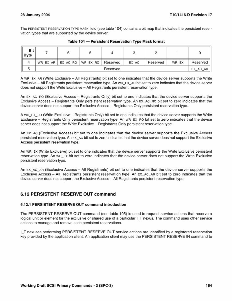
28 January 2004 T10/1416-D Revision 17
The PERSISTENT RESERVATION TYPE MASK field (see table 104) contains a bit map that indicates the persistent reser-vation types that are supported by the device server.
A WR_EX_AR (Write Exclusive – All Registrants) bit set to one indicates that the device server supports the WriteExclusive – All Registrants persistent reservation type. An WR_EX_AR bit set to zero indicates that the device serverdoes not support the Write Exclusive – All Registrants persistent reservation type.
An EX_AC_RO (Exclusive Access – Registrants Only) bit set to one indicates that the device server supports theExclusive Access – Registrants Only persistent reservation type. An EX_AC_RO bit set to zero indicates that thedevice server does not support the Exclusive Access – Registrants Only persistent reservation type.
A WR_EX_RO (Write Exclusive – Registrants Only) bit set to one indicates that the device server supports the WriteExclusive – Registrants Only persistent reservation type. An WR_EX_RO bit set to zero indicates that the deviceserver does not support the Write Exclusive – Registrants Only persistent reservation type.
An EX_AC (Exclusive Access) bit set to one indicates that the device server supports the Exclusive Accesspersistent reservation type. An EX_AC bit set to zero indicates that the device server does not support the ExclusiveAccess persistent reservation type.
An WR_EX (Write Exclusive) bit set to one indicates that the device server supports the Write Exclusive persistentreservation type. An WR_EX bit set to zero indicates that the device server does not support the Write Exclusivepersistent reservation type.
An EX_AC_AR (Exclusive Access – All Registrants) bit set to one indicates that the device server supports theExclusive Access – All Registrants persistent reservation type. An EX_AC_AR bit set to zero indicates that thedevice server does not support the Exclusive Access – All Registrants persistent reservation type.
6.12 PERSISTENT RESERVE OUT command
6.12.1 PERSISTENT RESERVE OUT command introduction
The PERSISTENT RESERVE OUT command (see table 105) is used to request service actions that reserve alogical unit or element for the exclusive or shared use of a particular I_T nexus. The command uses other serviceactions to manage and remove such persistent reservations.
I_T nexuses performing PERSISTENT RESERVE OUT service actions are identified by a registered reservationkey provided by the application client. An application client may use the PERSISTENT RESERVE IN command to
Table 104 — Persistent Reservation Type Mask format
BitByte
7 6 5 4 3 2 1 0
4 WR_EX_AR EX_AC_RO WR_EX_RO Reserved EX_AC Reserved WR_EX Reserved
5 Reserved EX_AC_AR
Working Draft SCSI Primary Commands - 3 (SPC-3) 164
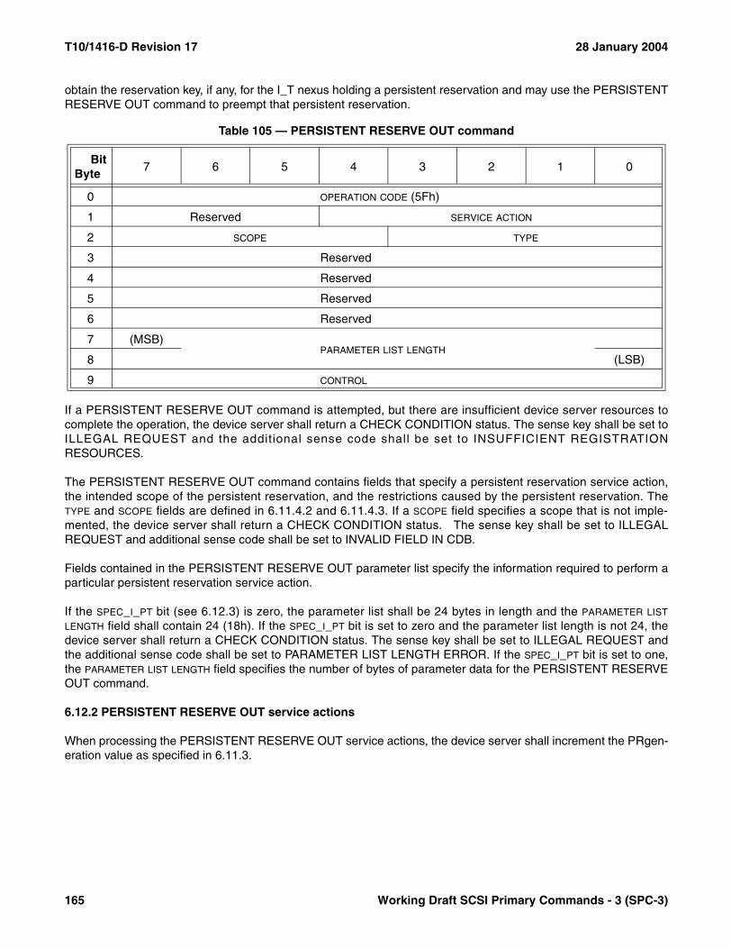
T10/1416-D Revision 17 28 January 2004
obtain the reservation key, if any, for the I_T nexus holding a persistent reservation and may use the PERSISTENTRESERVE OUT command to preempt that persistent reservation.
If a PERSISTENT RESERVE OUT command is attempted, but there are insufficient device server resources tocomplete the operation, the device server shall return a CHECK CONDITION status. The sense key shall be set toILLEGAL REQUEST and the additional sense code shall be set to INSUFFICIENT REGISTRATIONRESOURCES.
The PERSISTENT RESERVE OUT command contains fields that specify a persistent reservation service action,the intended scope of the persistent reservation, and the restrictions caused by the persistent reservation. TheTYPE and SCOPE fields are defined in 6.11.4.2 and 6.11.4.3. If a SCOPE field specifies a scope that is not imple-mented, the device server shall return a CHECK CONDITION status. The sense key shall be set to ILLEGALREQUEST and additional sense code shall be set to INVALID FIELD IN CDB.
Fields contained in the PERSISTENT RESERVE OUT parameter list specify the information required to perform aparticular persistent reservation service action.
If the SPEC_I_PT bit (see 6.12.3) is zero, the parameter list shall be 24 bytes in length and the PARAMETER LIST
LENGTH field shall contain 24 (18h). If the SPEC_I_PT bit is set to zero and the parameter list length is not 24, thedevice server shall return a CHECK CONDITION status. The sense key shall be set to ILLEGAL REQUEST andthe additional sense code shall be set to PARAMETER LIST LENGTH ERROR. If the SPEC_I_PT bit is set to one,the PARAMETER LIST LENGTH field specifies the number of bytes of parameter data for the PERSISTENT RESERVEOUT command.
6.12.2 PERSISTENT RESERVE OUT service actions
When processing the PERSISTENT RESERVE OUT service actions, the device server shall increment the PRgen-eration value as specified in 6.11.3.
Table 105 — PERSISTENT RESERVE OUT command
BitByte
7 6 5 4 3 2 1 0
0 OPERATION CODE (5Fh)
1 Reserved SERVICE ACTION
2 SCOPE TYPE
3 Reserved
4 Reserved
5 Reserved
6 Reserved
7 (MSB)PARAMETER LIST LENGTH
8 (LSB)
9 CONTROL
165 Working Draft SCSI Primary Commands - 3 (SPC-3)

28 January 2004 T10/1416-D Revision 17
The PERSISTENT RESERVE OUT command service actions are defined in table 106.
The parameter list values for each service action are specified in 6.12.3.
Table 106 — PERSISTENT RESERVE OUT service action codes
Code Name Description
PRGENERATION field incremented
(see 6.11.3)
00h REGISTER Register a reservation key with the device server (see 5.6.5) or unregister a reservation key (see 5.6.8.3).
Yes
01h RESERVE Creates a persistent reservation having a specified SCOPE and TYPE (see 5.6.6). The SCOPE and TYPE of a persistent reservation are defined in 6.11.4.2 and 6.11.4.3.
No
02h RELEASE Releases the selected persistent reservation (see 5.6.8.2).
No
03h CLEAR Clears all reservation keys (i.e., registrations) and all persistent reservations (see 5.6.8.6).
Yes
04h PREEMPT Preempts persistent reservations and/or removes registrations (see 5.6.8.4).
Yes
05h PREEMPT AND ABORT
Preempts persistent reservations and/or removes registrations and aborts all tasks for all preempted I_T nexuses (see 5.6.8.4 and 5.6.8.5).
Yes
06h REGISTER AND IGNORE EXISTING KEY
Register a reservation key with the device server (see 5.6.5) or unregister a reservation key (see 5.6.8.3).
Yes
07h - 1Fh Reserved
Working Draft SCSI Primary Commands - 3 (SPC-3) 166
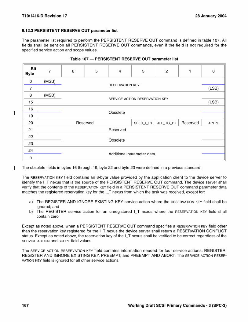
T10/1416-D Revision 17 28 January 2004
6.12.3 PERSISTENT RESERVE OUT parameter list
The parameter list required to perform the PERSISTENT RESERVE OUT command is defined in table 107. Allfields shall be sent on all PERSISTENT RESERVE OUT commands, even if the field is not required for thespecified service action and scope values.
The obsolete fields in bytes 16 through 19, byte 22 and byte 23 were defined in a previous standard.
The RESERVATION KEY field contains an 8-byte value provided by the application client to the device server toidentify the I_T nexus that is the source of the PERSISTENT RESERVE OUT command. The device server shallverify that the contents of the RESERVATION KEY field in a PERSISTENT RESERVE OUT command parameter datamatches the registered reservation key for the I_T nexus from which the task was received, except for:
a) The REGISTER AND IGNORE EXISTING KEY service action where the RESERVATION KEY field shall beignored; and
b) The REGISTER service action for an unregistered I_T nexus where the RESERVATION KEY field shallcontain zero.
Except as noted above, when a PERSISTENT RESERVE OUT command specifies a RESERVATION KEY field otherthan the reservation key registered for the I_T nexus the device server shall return a RESERVATION CONFLICTstatus. Except as noted above, the reservation key of the I_T nexus shall be verified to be correct regardless of theSERVICE ACTION and SCOPE field values.
The SERVICE ACTION RESERVATION KEY field contains information needed for four service actions: REGISTER,REGISTER AND IGNORE EXISTING KEY, PREEMPT, and PREEMPT AND ABORT. The SERVICE ACTION RESER-VATION KEY field is ignored for all other service actions.
Table 107 — PERSISTENT RESERVE OUT parameter list
BitByte
7 6 5 4 3 2 1 0
0 (MSB)RESERVATION KEY
7 (LSB)
8 (MSB)SERVICE ACTION RESERVATION KEY
15 (LSB)
16Obsolete
19
20 Reserved SPEC_I_PT ALL_TG_PT Reserved APTPL
21 Reserved
22Obsolete
23
24Additional parameter data
n
167 Working Draft SCSI Primary Commands - 3 (SPC-3)
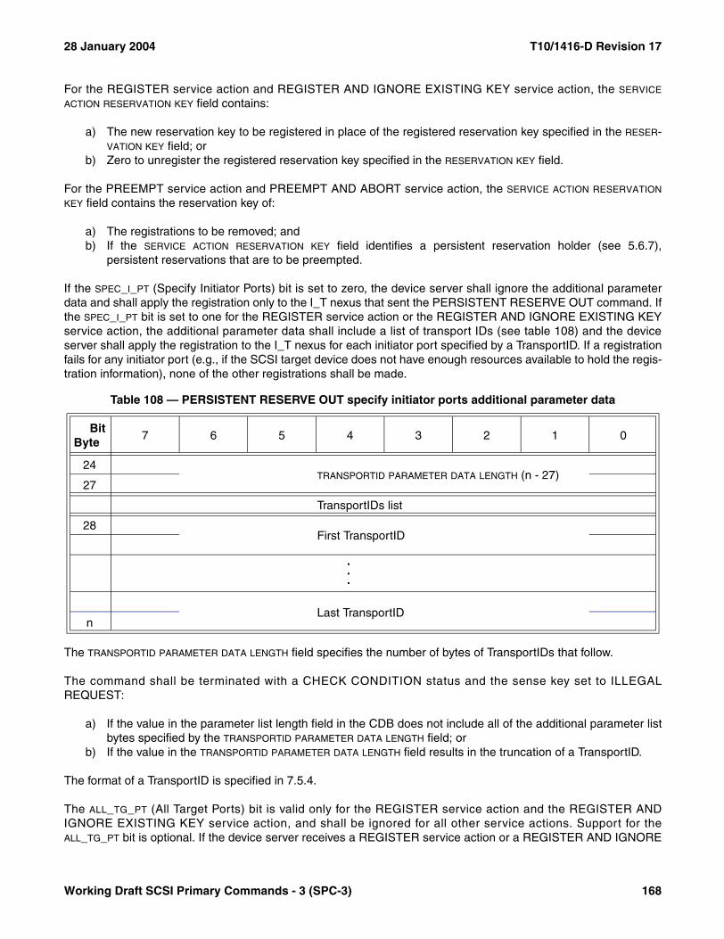
28 January 2004 T10/1416-D Revision 17
For the REGISTER service action and REGISTER AND IGNORE EXISTING KEY service action, the SERVICE
ACTION RESERVATION KEY field contains:
a) The new reservation key to be registered in place of the registered reservation key specified in the RESER-VATION KEY field; or
b) Zero to unregister the registered reservation key specified in the RESERVATION KEY field.
For the PREEMPT service action and PREEMPT AND ABORT service action, the SERVICE ACTION RESERVATION
KEY field contains the reservation key of:
a) The registrations to be removed; andb) If the SERVICE ACTION RESERVATION KEY field identifies a persistent reservation holder (see 5.6.7),
persistent reservations that are to be preempted.
If the SPEC_I_PT (Specify Initiator Ports) bit is set to zero, the device server shall ignore the additional parameterdata and shall apply the registration only to the I_T nexus that sent the PERSISTENT RESERVE OUT command. Ifthe SPEC_I_PT bit is set to one for the REGISTER service action or the REGISTER AND IGNORE EXISTING KEYservice action, the additional parameter data shall include a list of transport IDs (see table 108) and the deviceserver shall apply the registration to the I_T nexus for each initiator port specified by a TransportID. If a registrationfails for any initiator port (e.g., if the SCSI target device does not have enough resources available to hold the regis-tration information), none of the other registrations shall be made.
The TRANSPORTID PARAMETER DATA LENGTH field specifies the number of bytes of TransportIDs that follow.
The command shall be terminated with a CHECK CONDITION status and the sense key set to ILLEGALREQUEST:
a) If the value in the parameter list length field in the CDB does not include all of the additional parameter listbytes specified by the TRANSPORTID PARAMETER DATA LENGTH field; or
b) If the value in the TRANSPORTID PARAMETER DATA LENGTH field results in the truncation of a TransportID.
The format of a TransportID is specified in 7.5.4.
The ALL_TG_PT (All Target Ports) bit is valid only for the REGISTER service action and the REGISTER ANDIGNORE EXISTING KEY service action, and shall be ignored for all other service actions. Support for theALL_TG_PT bit is optional. If the device server receives a REGISTER service action or a REGISTER AND IGNORE
Table 108 — PERSISTENT RESERVE OUT specify initiator ports additional parameter data
BitByte
7 6 5 4 3 2 1 0
24TRANSPORTID PARAMETER DATA LENGTH (n - 27)
27
TransportIDs list
28First TransportID
.
.
.
Last TransportIDn
Working Draft SCSI Primary Commands - 3 (SPC-3) 168

T10/1416-D Revision 17 28 January 2004
EXISTING KEY service action with the ALL_TG_PT bit set to one, it shall create the specified registration on alltarget ports in the target device (i.e., as if the same registration request had been received individually througheach target port). If the device server receives a REGISTER service action or a REGISTER AND IGNOREEXISTING KEY service action with the ALL_TG_PT bit set to zero, it shall apply the registration only to the target portthrough which the PERSISTENT RESERVE OUT command was received.
The APTPL (Activate Persist Through Power Loss) bit is valid only for the REGISTER service action and theREGISTER AND IGNORE EXISTING KEY service action, and shall be ignored for all other service actions.Support for an APTPL bit equal to one is optional. If a device server that does not support an APTPL bit set to onereceives that value in a REGISTER service action or a REGISTER AND IGNORE EXISTING KEY service action,the device server shall return a CHECK CONDITION status. The sense key shall be set to ILLEGAL REQUESTand additional sense code shall be set to INVALID FIELD IN PARAMETER LIST.
If the last valid APTPL bit value received by the device server is zero, the loss of power in the SCSI target deviceshall release the persistent reservation for the logical unit and remove all registered reservation keys (see 5.6.5). Ifthe last valid APTPL bit value received by the device server is one, the logical unit shall retain any persistent reser-vation(s) that may be present and all reservation keys (i.e., registrations) for all I_T nexuses even if power is lostand later returned (see 5.6.3).
Table 109 summarizes which fields are set by the application client and interpreted by the device server for eachservice action and scope value.
Table 109 — PERSISTENT RESERVE OUT service actions and valid parameters (part 1 of 2)
Service action Allowed SCOPE
Parameters (part 1 of 2)
TYPE
RESERVATION
KEY
SERVICE ACTION RESERVATION
KEY APTPL
REGISTER ignored ignored valid valid valid
REGISTER AND IGNORE EXISTING KEY
ignoredignored ignored valid valid
RESERVE LU_SCOPE valid valid ignored ignored
RELEASE LU_SCOPE valid valid ignored ignored
CLEAR ignored ignored valid ignored ignored
PREEMPT LU_SCOPE valid valid valid ignored
PREEMPT AND ABORT
LU_SCOPEvalid valid valid ignored
169 Working Draft SCSI Primary Commands - 3 (SPC-3)

28 January 2004 T10/1416-D Revision 17
Table 109 — PERSISTENT RESERVE OUT service actions and valid parameters (part 2 of 2)
Service action Allowed SCOPE
Parameters (part 2 of 2)
ALL_TG_PT SPEC_I_PT
REGISTER ignored valid valid
REGISTER AND IGNORE EXISTING KEY
ignored valid valid
RESERVE LU_SCOPE ignored ignored
RELEASE LU_SCOPE ignored ignored
CLEAR ignored ignored ignored
PREEMPT LU_SCOPE ignored ignored
PREEMPT AND ABORT
LU_SCOPE ignored ignored
Working Draft SCSI Primary Commands - 3 (SPC-3) 170
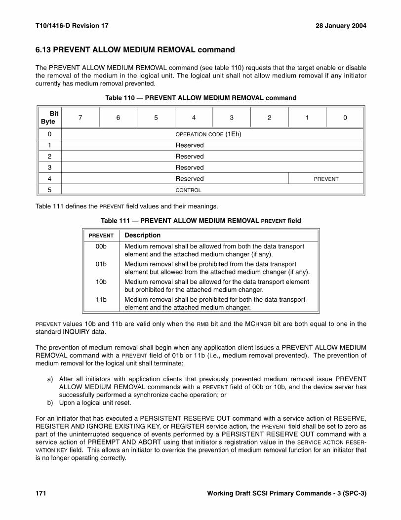
T10/1416-D Revision 17 28 January 2004
6.13 PREVENT ALLOW MEDIUM REMOVAL command
The PREVENT ALLOW MEDIUM REMOVAL command (see table 110) requests that the target enable or disablethe removal of the medium in the logical unit. The logical unit shall not allow medium removal if any initiatorcurrently has medium removal prevented.
Table 111 defines the PREVENT field values and their meanings.
PREVENT values 10b and 11b are valid only when the RMB bit and the MCHNGR bit are both equal to one in thestandard INQUIRY data.
The prevention of medium removal shall begin when any application client issues a PREVENT ALLOW MEDIUMREMOVAL command with a PREVENT field of 01b or 11b (i.e., medium removal prevented). The prevention ofmedium removal for the logical unit shall terminate:
a) After all initiators with application clients that previously prevented medium removal issue PREVENTALLOW MEDIUM REMOVAL commands with a PREVENT field of 00b or 10b, and the device server hassuccessfully performed a synchronize cache operation; or
b) Upon a logical unit reset.
For an initiator that has executed a PERSISTENT RESERVE OUT command with a service action of RESERVE,REGISTER AND IGNORE EXISTING KEY, or REGISTER service action, the PREVENT field shall be set to zero aspart of the uninterrupted sequence of events performed by a PERSISTENT RESERVE OUT command with aservice action of PREEMPT AND ABORT using that initiator's registration value in the SERVICE ACTION RESER-VATION KEY field. This allows an initiator to override the prevention of medium removal function for an initiator thatis no longer operating correctly.
Table 110 — PREVENT ALLOW MEDIUM REMOVAL command
BitByte
7 6 5 4 3 2 1 0
0 OPERATION CODE (1Eh)
1 Reserved
2 Reserved
3 Reserved
4 Reserved PREVENT
5 CONTROL
Table 111 — PREVENT ALLOW MEDIUM REMOVAL PREVENT field
PREVENT Description
00b Medium removal shall be allowed from both the data transport element and the attached medium changer (if any).
01b Medium removal shall be prohibited from the data transport element but allowed from the attached medium changer (if any).
10b Medium removal shall be allowed for the data transport element but prohibited for the attached medium changer.
11b Medium removal shall be prohibited for both the data transport element and the attached medium changer.
171 Working Draft SCSI Primary Commands - 3 (SPC-3)

28 January 2004 T10/1416-D Revision 17
While a prevention of medium removal condition is in effect, the target shall inhibit mechanisms that normally allowremoval of the medium by an operator.
6.14 READ ATTRIBUTE command
6.14.1 READ ATTRIBUTE command introduction
The READ ATTRIBUTE command (see table 112) allows an application client to read attribute values from mediumauxiliary memory.
If the medium auxiliary memory is not accessible because there is no medium present, the READ ATTRIBUTEcommand shall be terminated with a CHECK CONDITION status. The sense key shall be set to NOT READY andthe additional sense code shall be set to MEDIUM NOT PRESENT.
If the medium is present but the medium auxiliary memory is not accessible, the READ ATTRIBUTE commandshall be terminated with a CHECK CONDITION status. The sense key shall be set to MEDIUM ERROR and theadditional sense code shall be set to LOGICAL UNIT NOT READY, AUXILIARY MEMORY NOT ACCESSIBLE.
If the medium auxiliary memory is not operational, the READ ATTRIBUTE command shall be terminated with aCHECK CONDITION status. The sense key shall be set to MEDIUM ERROR and the additional sense code shallbe set to AUXILIARY MEMORY READ ERROR.
Table 112 — READ ATTRIBUTE command
BitByte
7 6 5 4 3 2 1 0
0 OPERATION CODE (8Ch)
1 Reserved SERVICE ACTION
2
Restricted (see SMC-2)3
4
5 VOLUME NUMBER
6 Reserved
7 PARTITION NUMBER
8 (MSB)FIRST ATTRIBUTE IDENTIFIER
9 (LSB)
10 (MSB)
ALLOCATION LENGTH11
12
13 (LSB)
14 Reserved
15 CONTROL
Working Draft SCSI Primary Commands - 3 (SPC-3) 172

T10/1416-D Revision 17 28 January 2004
The service actions defined for the READ ATTRIBUTE command are shown in table 113.
The VOLUME NUMBER field specifies a volume (see SSC-2) within the medium auxiliary memory. The number ofvolumes of the medium auxiliary memory shall equal that of the attached medium. If the medium only has a singlevolume, then its volume number shall be zero.
The PARTITION NUMBER field specifies a partition (see SSC-2) within a volume. The number of partitions of themedium auxiliary memory shall equal that of the attached medium. If the medium only has a single partition, thenits partition number shall be zero.
If the combination of volume number and partition number is not valid, the command shall be terminated with aCHECK CONDITION status. The sense key shall be set to ILLEGAL REQUEST, and the additional sense codeshall be set to INVALID FIELD IN CDB.
The FIRST ATTRIBUTE IDENTIFIER field specifies the attribute identifier of the first attribute to be returned. If thespecified attribute is in the unsupported state or nonexistent state (see 5.11), the READ ATTRIBUTE commandshall be terminated with a CHECK CONDITION status. The sense key shall be set to ILLEGAL REQUEST and theadditional sense code shall be set to INVALID FIELD IN CDB.
The ALLOCATION LENGTH field specifies how many bytes have been allocated for the returned parameter list. If thelength is not sufficient to contain the entire parameter list, the first portion of the list shall be returned. This shall notbe considered an error. If the remainder of the list is required, the application client should either send a new READATRRIBUTE command with an allocation length large enough to contain the entire parameter list or use the FIRST
ATTRIBUTE IDENTIFIER field to restrict the attributes returned.
The format of parameter data returned by the READ ATTRIBUTE command depends on the service actionspecified.
6.14.2 ATTRIBUTE VALUES service action
The READ ATTRIBUTE command with ATTRIBUTE VALUES service action returns parameter data containing theattributes specified by the PARTITION NUMBER, VOLUME NUMBER, and FIRST ATTRIBUTE IDENTIFIER fields in the CDB.
Table 113 — READ ATTRIBUTE service action codes
Code Name Description Subclause
00h ATTRIBUTE VALUES Return attribute values. 6.14.2
01h ATTRIBUTE LIST Return a list of available attribute identifiers, identifiers that are not in the nonexistent state or unsupported state (see 5.11).
6.14.3
02h VOLUME LIST Return a list of known volume numbers. 6.14.4
03h PARTITION LIST Return a list of known partition numbers. 6.14.5
04h Restricted
05h-1Fh Reserved
173 Working Draft SCSI Primary Commands - 3 (SPC-3)
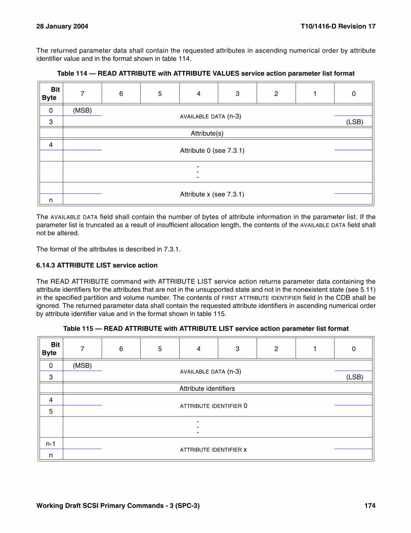
28 January 2004 T10/1416-D Revision 17
The returned parameter data shall contain the requested attributes in ascending numerical order by attributeidentifier value and in the format shown in table 114.
The AVAILABLE DATA field shall contain the number of bytes of attribute information in the parameter list. If theparameter list is truncated as a result of insufficient allocation length, the contents of the AVAILABLE DATA field shallnot be altered.
The format of the attributes is described in 7.3.1.
6.14.3 ATTRIBUTE LIST service action
The READ ATTRIBUTE command with ATTRIBUTE LIST service action returns parameter data containing theattribute identifiers for the attributes that are not in the unsupported state and not in the nonexistent state (see 5.11)in the specified partition and volume number. The contents of FIRST ATTRIBUTE IDENTIFIER field in the CDB shall beignored. The returned parameter data shall contain the requested attribute identifiers in ascending numerical orderby attribute identifier value and in the format shown in table 115.
Table 114 — READ ATTRIBUTE with ATTRIBUTE VALUES service action parameter list format
BitByte
7 6 5 4 3 2 1 0
0 (MSB)AVAILABLE DATA (n-3)
3 (LSB)
Attribute(s)
4Attribute 0 (see 7.3.1)
.
.
.
Attribute x (see 7.3.1)n
Table 115 — READ ATTRIBUTE with ATTRIBUTE LIST service action parameter list format
BitByte
7 6 5 4 3 2 1 0
0 (MSB)AVAILABLE DATA (n-3)
3 (LSB)
Attribute identifiers
4ATTRIBUTE IDENTIFIER 0
5...
n-1ATTRIBUTE IDENTIFIER x
n
Working Draft SCSI Primary Commands - 3 (SPC-3) 174
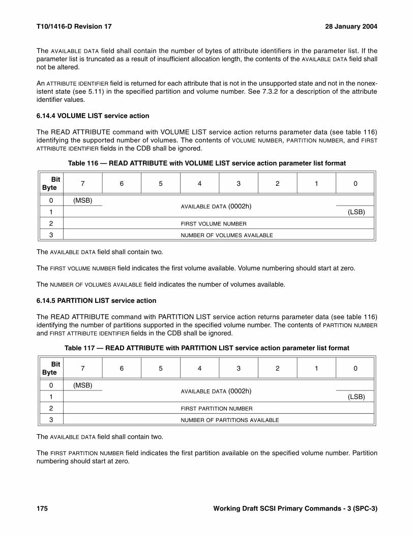
T10/1416-D Revision 17 28 January 2004
The AVAILABLE DATA field shall contain the number of bytes of attribute identifiers in the parameter list. If theparameter list is truncated as a result of insufficient allocation length, the contents of the AVAILABLE DATA field shallnot be altered.
An ATTRIBUTE IDENTIFIER field is returned for each attribute that is not in the unsupported state and not in the nonex-istent state (see 5.11) in the specified partition and volume number. See 7.3.2 for a description of the attributeidentifier values.
6.14.4 VOLUME LIST service action
The READ ATTRIBUTE command with VOLUME LIST service action returns parameter data (see table 116)identifying the supported number of volumes. The contents of VOLUME NUMBER, PARTITION NUMBER, and FIRST
ATTRIBUTE IDENTIFIER fields in the CDB shall be ignored.
The AVAILABLE DATA field shall contain two.
The FIRST VOLUME NUMBER field indicates the first volume available. Volume numbering should start at zero.
The NUMBER OF VOLUMES AVAILABLE field indicates the number of volumes available.
6.14.5 PARTITION LIST service action
The READ ATTRIBUTE command with PARTITION LIST service action returns parameter data (see table 116)identifying the number of partitions supported in the specified volume number. The contents of PARTITION NUMBER
and FIRST ATTRIBUTE IDENTIFIER fields in the CDB shall be ignored.
The AVAILABLE DATA field shall contain two.
The FIRST PARTITION NUMBER field indicates the first partition available on the specified volume number. Partitionnumbering should start at zero.
Table 116 — READ ATTRIBUTE with VOLUME LIST service action parameter list format
BitByte
7 6 5 4 3 2 1 0
0 (MSB)AVAILABLE DATA (0002h)
1 (LSB)
2 FIRST VOLUME NUMBER
3 NUMBER OF VOLUMES AVAILABLE
Table 117 — READ ATTRIBUTE with PARTITION LIST service action parameter list format
BitByte
7 6 5 4 3 2 1 0
0 (MSB)AVAILABLE DATA (0002h)
1 (LSB)
2 FIRST PARTITION NUMBER
3 NUMBER OF PARTITIONS AVAILABLE
175 Working Draft SCSI Primary Commands - 3 (SPC-3)

28 January 2004 T10/1416-D Revision 17
The NUMBER OF PARTITIONS AVAILABLE field indicates the number of partitions available on the specified volumenumber.
6.15 READ BUFFER command
6.15.1 READ BUFFER command introduction
The READ BUFFER command (see table 118) is used in conjunction with the WRITE BUFFER command as adiagnostic function for testing memory in the SCSI device and the integrity of the service delivery subsystem. Thiscommand shall not alter the medium.
The function of this command and the meaning of fields within the CDB depend on the contents of the MODE field.The MODE field is defined in table 119.
Table 118 — READ BUFFER command
BitByte
7 6 5 4 3 2 1 0
0 OPERATION CODE (3Ch)
1 Reserved MODE
2 BUFFER ID
3 (MSB)
BUFFER OFFSET4
5 (LSB)
6 (MSB)
ALLOCATION LENGTH7
8 (LSB)
9 CONTROL
Table 119 — READ BUFFER MODE field
MODE DescriptionImplementation requirements
00h Combined header and data Optional
01h Vendor specific Vendor specific
02h Data Optional
03h Descriptor Optional
0Ah Echo buffer Optional
0Bh Echo buffer descriptor Optional
1Ah Enable expander communications protocol and Echo buffer Optional
04h - 09h Reserved
0Ch - 19h Reserved
1Bh - 1Fh Reserved
Working Draft SCSI Primary Commands - 3 (SPC-3) 176

T10/1416-D Revision 17 28 January 2004
6.15.2 Combined header and data mode (00h)
In this mode, a four-byte header followed by data bytes is returned to the application client in the Data-In Buffer.The BUFFER ID and the BUFFER OFFSET fields are reserved.
The four-byte READ BUFFER header (see table 120) is followed by data bytes from the buffer.
The BUFFER CAPACITY field specifies the total number of data bytes available in the buffer. This number is notreduced to reflect the allocation length; nor is it reduced to reflect the actual number of bytes written using theWRITE BUFFER command. Following the READ BUFFER header, the device server shall transfer data from thebuffer. The device server shall terminate filling the Data-In Buffer when allocation length bytes of header plus datahave been transferred or when all available header and buffer data have been transferred to the application client,whichever is less.
6.15.3 Vendor specific mode (01h)
In this mode, the meanings of the BUFFER ID, BUFFER OFFSET, and ALLOCATION LENGTH fields are not specified bythis standard.
6.15.4 Data mode (02h)
In this mode, the Data-In Buffer is filled only with logical unit buffer data. The BUFFER ID field identifies a specificbuffer within the logical unit from which data shall be transferred. The vendor assigns buffer ID codes to bufferswithin the logical unit. Buffer ID zero shall be supported. If more than one buffer is supported, additional buffer IDcodes shall be assigned contiguously, beginning with one. Buffer ID code assignments for the READ BUFFERcommand shall be the same as for the WRITE BUFFER command. If an unsupported buffer ID code is selected,the device server shall return CHECK CONDITION status, shall set the sense key to ILLEGAL REQUEST, and setthe additional sense code to INVALID FIELD IN CDB.
The device server shall terminate filling the Data-In Buffer when allocation length bytes have been transferred orwhen all the available data from the buffer has been transferred to the application client, whichever amount is less.
The BUFFER OFFSET field contains the byte offset within the specified buffer from which data shall be transferred.The application client should conform to the offset boundary requirements returned in the READ BUFFERdescriptor (see 6.15.5). If the device server is unable to accept the specified buffer offset, it shall return CHECKCONDITION status, shall set the sense key to ILLEGAL REQUEST, and set the additional sense code to INVALIDFIELD IN CDB.
6.15.5 Descriptor mode (03h)
In this mode, a maximum of four bytes of READ BUFFER descriptor information is returned. The device servershall return the descriptor information for the buffer specified by the BUFFER ID field (see the description of the bufferID in 6.15.4). If there is no buffer associated with the specified buffer ID, the device server shall return all zeros inthe READ BUFFER descriptor. The BUFFER OFFSET field is reserved in this mode. The allocation length should be
Table 120 — READ BUFFER header
BitByte
7 6 5 4 3 2 1 0
0 Reserved
1BUFFER CAPACITY
3
177 Working Draft SCSI Primary Commands - 3 (SPC-3)
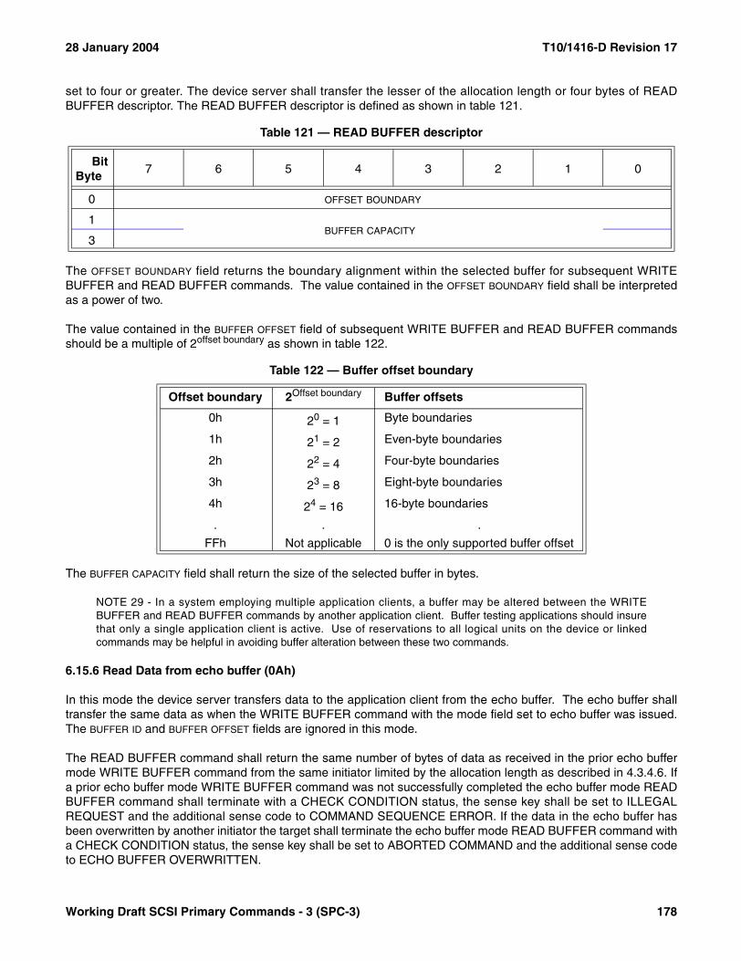
28 January 2004 T10/1416-D Revision 17
set to four or greater. The device server shall transfer the lesser of the allocation length or four bytes of READBUFFER descriptor. The READ BUFFER descriptor is defined as shown in table 121.
The OFFSET BOUNDARY field returns the boundary alignment within the selected buffer for subsequent WRITEBUFFER and READ BUFFER commands. The value contained in the OFFSET BOUNDARY field shall be interpretedas a power of two.
The value contained in the BUFFER OFFSET field of subsequent WRITE BUFFER and READ BUFFER commandsshould be a multiple of 2offset boundary as shown in table 122.
The BUFFER CAPACITY field shall return the size of the selected buffer in bytes.
NOTE 29 - In a system employing multiple application clients, a buffer may be altered between the WRITEBUFFER and READ BUFFER commands by another application client. Buffer testing applications should insurethat only a single application client is active. Use of reservations to all logical units on the device or linkedcommands may be helpful in avoiding buffer alteration between these two commands.
6.15.6 Read Data from echo buffer (0Ah)
In this mode the device server transfers data to the application client from the echo buffer. The echo buffer shalltransfer the same data as when the WRITE BUFFER command with the mode field set to echo buffer was issued.The BUFFER ID and BUFFER OFFSET fields are ignored in this mode.
The READ BUFFER command shall return the same number of bytes of data as received in the prior echo buffermode WRITE BUFFER command from the same initiator limited by the allocation length as described in 4.3.4.6. Ifa prior echo buffer mode WRITE BUFFER command was not successfully completed the echo buffer mode READBUFFER command shall terminate with a CHECK CONDITION status, the sense key shall be set to ILLEGALREQUEST and the additional sense code to COMMAND SEQUENCE ERROR. If the data in the echo buffer hasbeen overwritten by another initiator the target shall terminate the echo buffer mode READ BUFFER command witha CHECK CONDITION status, the sense key shall be set to ABORTED COMMAND and the additional sense codeto ECHO BUFFER OVERWRITTEN.
Table 121 — READ BUFFER descriptor
BitByte
7 6 5 4 3 2 1 0
0 OFFSET BOUNDARY
1BUFFER CAPACITY
3
Table 122 — Buffer offset boundary
Offset boundary 2Offset boundary Buffer offsets
0h 20 = 1 Byte boundaries
1h 21 = 2 Even-byte boundaries
2h 22 = 4 Four-byte boundaries
3h 23 = 8 Eight-byte boundaries
4h 24 = 16 16-byte boundaries
. . .
FFh Not applicable 0 is the only supported buffer offset
Working Draft SCSI Primary Commands - 3 (SPC-3) 178

T10/1416-D Revision 17 28 January 2004
The initiator may send a READ BUFFER command requesting the echo buffer descriptor prior to a WRITEBUFFER command.
If an echo buffer mode WRITE BUFFER command is successful then the initiator may send multiple echo buffermode READ BUFFER commands to read the echo buffer data multiple times.
6.15.7 Echo buffer descriptor mode (0Bh)
In this mode, a maximum of four bytes of READ BUFFER descriptor information is returned. The device servershall return the descriptor information for the echo buffer. If there is no echo buffer implemented, the device servershall return all zeros in the READ BUFFER descriptor. The BUFFER OFFSET field is reserved in this mode. Theallocation length should be set to four or greater. The device server shall transfer the lesser of the allocation lengthor four bytes of READ BUFFER descriptor. The READ BUFFER descriptor is defined as shown in table 123.
The BUFFER CAPACITY field shall return the size of the echo buffer in bytes aligned to a four-byte boundary. Themaximum echo buffer size is 4096 bytes.
If the echo buffer is implemented then the echo buffer descriptor shall be implemented.
An echo buffer overwritten supported (EBOS) bit set to one indicates either:
a) The target returns the ECHO BUFFER OVERWRITTEN additional sense code if the data being read fromthe echo buffer is not the data previously written by the same initiator, or
b) The target ensures echo buffer data from each initiator is the same as that previously written by the sameinitiator.
An EBOS bit set to zero specifies that the echo buffer may be overwritten by other initiators or interveningcommands.
6.15.8 Enable expander communications protocol and Echo buffer (1Ah)
Receipt of a READ BUFFER command with this mode (1Ah) causes a communicative expander (see SPI-5) toenter the expanded communications protocol mode. Device servers in SCSI target devices that receive a READBUFFER command with this mode shall process it as if it were a READ BUFFER command with mode 0Ah (see6.15.6).
Table 123 — Echo buffer descriptor
BitByte
7 6 5 4 3 2 1 0
0 Reserved EBOS
1 Reserved
2 Reserved (MSB)
3 BUFFER CAPACITY (LSB)
179 Working Draft SCSI Primary Commands - 3 (SPC-3)
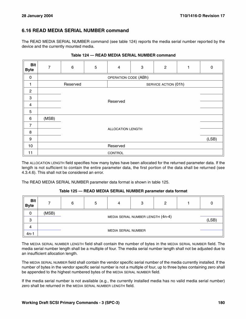
28 January 2004 T10/1416-D Revision 17
6.16 READ MEDIA SERIAL NUMBER command
The READ MEDIA SERIAL NUMBER command (see table 124) reports the media serial number reported by thedevice and the currently mounted media.
The ALLOCATION LENGTH field specifies how many bytes have been allocated for the returned parameter data. If thelength is not sufficient to contain the entire parameter data, the first portion of the data shall be returned (see4.3.4.6). This shall not be considered an error.
The READ MEDIA SERIAL NUMBER parameter data format is shown in table 125.
The MEDIA SERIAL NUMBER LENGTH field shall contain the number of bytes in the MEDIA SERIAL NUMBER field. Themedia serial number length shall be a multiple of four. The media serial number length shall not be adjusted due toan insufficient allocation length.
The MEDIA SERIAL NUMBER field shall contain the vendor specific serial number of the media currently installed. If thenumber of bytes in the vendor specific serial number is not a multiple of four, up to three bytes containing zero shallbe appended to the highest numbered bytes of the MEDIA SERIAL NUMBER field.
If the media serial number is not available (e.g., the currently installed media has no valid media serial number)zero shall be returned in the MEDIA SERIAL NUMBER LENGTH field.
Table 124 — READ MEDIA SERIAL NUMBER command
BitByte
7 6 5 4 3 2 1 0
0 OPERATION CODE (ABh)
1 Reserved SERVICE ACTION (01h)
2
Reserved3
4
5
6 (MSB)
ALLOCATION LENGTH7
8
9 (LSB)
10 Reserved
11 CONTROL
Table 125 — READ MEDIA SERIAL NUMBER parameter data format
BitByte
7 6 5 4 3 2 1 0
0 (MSB)MEDIA SERIAL NUMBER LENGTH (4n-4)
3 (LSB)
4MEDIA SERIAL NUMBER
4n-1
Working Draft SCSI Primary Commands - 3 (SPC-3) 180
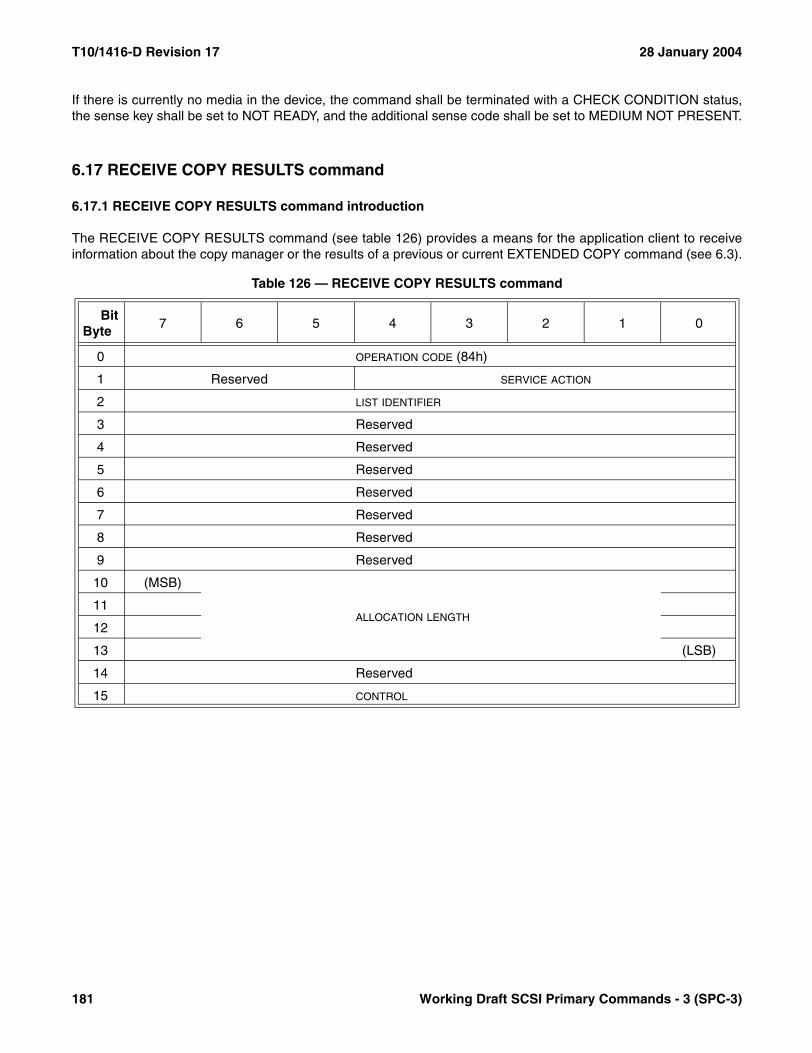
T10/1416-D Revision 17 28 January 2004
If there is currently no media in the device, the command shall be terminated with a CHECK CONDITION status,the sense key shall be set to NOT READY, and the additional sense code shall be set to MEDIUM NOT PRESENT.
6.17 RECEIVE COPY RESULTS command
6.17.1 RECEIVE COPY RESULTS command introduction
The RECEIVE COPY RESULTS command (see table 126) provides a means for the application client to receiveinformation about the copy manager or the results of a previous or current EXTENDED COPY command (see 6.3).
Table 126 — RECEIVE COPY RESULTS command
BitByte
7 6 5 4 3 2 1 0
0 OPERATION CODE (84h)
1 Reserved SERVICE ACTION
2 LIST IDENTIFIER
3 Reserved
4 Reserved
5 Reserved
6 Reserved
7 Reserved
8 Reserved
9 Reserved
10 (MSB)
ALLOCATION LENGTH11
12
13 (LSB)
14 Reserved
15 CONTROL
181 Working Draft SCSI Primary Commands - 3 (SPC-3)

28 January 2004 T10/1416-D Revision 17
The service actions defined for the RECEIVE COPY RESULTS command are shown in table 127.
The LIST IDENTIFIER field identifies the EXTENDED COPY command (see 6.3) about which information is desired.The RECEIVE COPY RESULTS command shall return information from the EXTENDED COPY commandreceived on the same I_T nexus with a list identifier that matches the list identifier specified in the RECEIVE COPYRESULTS CDB.
If the LIST IDENTIFIER field identifies the EXTENDED COPY command that had the NRCR bit set to one in theparameter data (see 6.3), the copy manager may respond to a RECEIVE COPY RESULTS command in the samemanner it would if the EXTENDED COPY command had never been received.
The actual length of the RECEIVE COPY RESULTS parameter data is available in the AVAILABLE DATA parameterdata field. The ALLOCATION LENGTH field in the CDB indicates how much space has been allocated for the returnedparameter list. If the length is not sufficient to contain the entire parameter list, the first portion of the list shall bereturned. This shall not be considered an error. If the remainder of the list is required, the application client shouldsend a new RECEIVE COPY RESULTS command with an ALLOCATION LENGTH field large enough to contain theentire parameter list.
Table 127 — RECEIVE COPY RESULTS service action codes
Code Name Description
Returns Data While EXTENDED COPY Is
In Progress
00h COPYSTATUS
Return the current copy status of the EXTENDED COPY command identified by the LIST IDENTIFIER field.
Yes
01h RECEIVE DATA
Return the held data read by EXTENDED COPY com-mand identified by the LIST IDENTIFIER field.
No
03h OPERATING PARAMETERS
Return copy manager operating parameters. Yes
04h FAILED SEGMENT DETAILS
Return copy target device sense data and other infor-mation about the progress of processing a segment descriptor whose processing was not completed during processing of the EXTENDED COPY command identi-fied by the LIST IDENTIFIER field.
No
05h-1Eh Reserved
1Fh Vendor Specific
Working Draft SCSI Primary Commands - 3 (SPC-3) 182

T10/1416-D Revision 17 28 January 2004
6.17.2 COPY STATUS service action
In response to the COPY STATUS service action, the copy manager shall return the current status of theEXTENDED COPY command (see 6.3) identified by the LIST IDENTIFIER field in the CDB. If no EXTENDED COPYcommand known to the copy manager has a matching list identifier, then the command shall be terminated with aCHECK CONDITION status, the sense key shall be set to ILLEGAL REQUEST, and the additional sense codeshall be set to INVALID FIELD IN CDB.
Table 128 shows the format of the information returned by the copy manager in response to the COPY STATUSservice action. If a device server supports the EXTENDED COPY command, it shall also support the RECEIVECOPY RESULTS command with COPY STATUS service action.
After completion of an EXTENDED COPY command, the copy manager shall preserve all data returned by aCOPY STATUS service action for a vendor specific period of time. The copy manager shall discard the COPYSTATUS data when:
a) A RECEIVE COPY RESULTS command with COPY STATUS service action is received on the same I_Tnexus with a matching list identifier;
b) When another EXTENDED COPY command is received on the same I_T nexus and the list identifiermatches the list identifier associated with the data preserved for the COPY STATUS service action;
c) When the copy manager detects a logical unit reset or I_T nexus loss; ord) When the copy manager requires the resources used to preserve the data.
The AVAILABLE DATA field shall contain the number of bytes present in the parameter data that follows.
The held data discarded (HDD) bit indicates whether held data has been discarded. If HDD bit is set to one, held datahas been discarded as described in 6.17.4. If HDD bit is set to zero, held data has not been discarded.
Table 128 — Parameter data for the COPY STATUS service action
BitByte
7 6 5 4 3 2 1 0
0 (MSB)AVAILABLE DATA (00000008h)
3 (LSB)
4 HDD COPY MANAGER STATUS
5 (MSB)SEGMENTS PROCESSED
6 (LSB)
7 TRANSFER COUNT UNITS
8 (MSB)TRANSFER COUNT
11 (LSB)
183 Working Draft SCSI Primary Commands - 3 (SPC-3)

28 January 2004 T10/1416-D Revision 17
The COPY MANAGER STATUS field contains the current status of the EXTENDED COPY command identified by theLIST IDENTIFIER field in the CDB as defined in table 129.
The SEGMENTS PROCESSED field contains the number of segments the copy manager has processed for theEXTENDED COPY command identified by the LIST IDENTIFIER field in the CDB including the segment currentlybeing processed. This field shall be zero if the copy manager has not yet begun processing segment descriptors.
The TRANSFER COUNT UNITS field specifies the units for the TRANSFER COUNT field as defined in table 130.
The TRANSFER COUNT field specifies the amount of data written to a destination device for the EXTENDED COPYcommand identified by the LIST IDENTIFIER field in the CDB prior to receiving the RECEIVE COPY RESULTScommand with COPY STATUS service action.
Table 129 — COPY MANAGER STATUS values
Value Meaning
00h Operation in progress
01h Operation completed without errors
02h Operation completed with errors
03h - 7Fh Reserved
Table 130 — COPY STATUS TRANSFER COUNT UNITS values
Value Meaning Binary Multiplier Name a
Multiplier to convert TRANSFER COUNT field to bytes
00h Bytes 1
01h Ki-bytes Kilobinary 210 or 1024
02h Mi-bytes Megabinary 220
03h Gi-bytes Gigabinary 230
04h Ti-bytes Terabinary 240
05h Pi-bytes Petabinary 250
06h Ei-bytes Exabinary 260
07h - FFh Reserveda This nomenclature is defined in ISO/IEC 60027-2-am2
(1999-01), Letter symbols to be used in electrical technology - Part 2: Telecommunications and electronics (Amendment 2).
Working Draft SCSI Primary Commands - 3 (SPC-3) 184
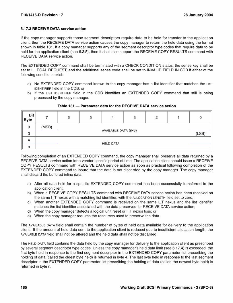
T10/1416-D Revision 17 28 January 2004
6.17.3 RECEIVE DATA service action
If the copy manager supports those segment descriptors require data to be held for transfer to the applicationclient, then the RECEIVE DATA service action causes the copy manager to return the held data using the formatshown in table 131. If a copy manager supports any of the segment descriptor type codes that require data to beheld for the application client (see 6.3.5), then it shall also support the RECEIVE COPY RESULTS command withRECEIVE DATA service action.
The EXTENDED COPY command shall be terminated with a CHECK CONDITION status, the sense key shall beset to ILLEGAL REQUEST, and the additional sense code shall be set to INVALID FIELD IN CDB if either of thefollowing conditions exist:
a) No EXTENDED COPY command known to the copy manager has a list identifier that matches the LIST
IDENTIFIER field in the CDB; orb) If the LIST IDENTIFIER field in the CDB identifies an EXTENDED COPY command that still is being
processed by the copy manager.
Following completion of an EXTENDED COPY command, the copy manager shall preserve all data returned by aRECEIVE DATA service action for a vendor specific period of time. The application client should issue a RECEIVECOPY RESULTS command with RECEIVE DATA service action as soon as practical following completion of theEXTENDED COPY command to insure that the data is not discarded by the copy manager. The copy managershall discard the buffered inline data:
a) After all data held for a specific EXTENDED COPY command has been successfully transferred to theapplication client;
b) When a RECEIVE COPY RESULTS command with RECEIVE DATA service action has been received onthe same I_T nexus with a matching list identifier, with the ALLOCATION LENGTH field set to zero;
c) When another EXTENDED COPY command is received on the same I_T nexus and the list identifiermatches the list identifier associated with the data preserved for RECEIVE DATA service action;
d) When the copy manager detects a logical unit reset or I_T nexus loss; ore) When the copy manager requires the resources used to preserve the data.
The AVAILABLE DATA field shall contain the number of bytes of held data available for delivery to the applicationclient. If the amount of held data sent to the application client is reduced due to insufficient allocation length, theAVAILABLE DATA field shall not be altered and the held data shall not be discarded.
The HELD DATA field contains the data held by the copy manager for delivery to the application client as prescribedby several segment descriptor type codes. Unless the copy manager’s held data limit (see 6.17.4) is exceeded, thefirst byte held in response to the first segment descriptor in the EXTENDED COPY parameter list prescribing theholding of data (called the oldest byte held) is returned in byte 4. The last byte held in response to the last segmentdescriptor in the EXTENDED COPY parameter list prescribing the holding of data (called the newest byte held) isreturned in byte n.
Table 131 — Parameter data for the RECEIVE DATA service action
BitByte
7 6 5 4 3 2 1 0
0 (MSB)AVAILABLE DATA (n-3)
3 (LSB)
4HELD DATA
n
185 Working Draft SCSI Primary Commands - 3 (SPC-3)

28 January 2004 T10/1416-D Revision 17
6.17.4 OPERATING PARAMETERS service action
In response to the OPERATING PARAMETERS service action, the copy manager shall return its operatingparameter information in the format shown in table 132. If a device server supports the EXTENDED COPYcommand (see 6.3), then it shall also support the RECEIVE COPY RESULTS command with OPERATINGPARAMETERS service action.
Table 132 — Parameter data for the OPERATING PARAMETERS service action
BitByte
7 6 5 4 3 2 1 0
0 (MSB)AVAILABLE DATA (n-3)
3 (LSB)
4Reserved
7
8 (MSB)MAXIMUM TARGET DESCRIPTOR COUNT
9 (LSB)
10 (MSB)MAXIMUM SEGMENT DESCRIPTOR COUNT
11 (LSB)
12 (MSB)MAXIMUM DESCRIPTOR LIST LENGTH
15 (LSB)
16 (MSB)MAXIMUM SEGMENT LENGTH
19 (LSB)
20 (MSB)MAXIMUM INLINE DATA LENGTH
23 (LSB)
24 (MSB)HELD DATA LIMIT
27 (LSB)
28 (MSB)MAXIMUM STREAM DEVICE TRANSFER SIZE
31 (LSB)
32Reserved
35
36 MAXIMUM CONCURRENT COPIES
37 DATA SEGMENT GRANULARITY (log 2)
38 INLINE DATA GRANULARITY (log 2)
39 HELD DATA GRANULARITY (log 2)
40Reserved
42
43 IMPLEMENTED DESCRIPTOR LIST LENGTH (n-43)
44List of implemented descriptor type codes (ordered)
n
Working Draft SCSI Primary Commands - 3 (SPC-3) 186

T10/1416-D Revision 17 28 January 2004
The AVAILABLE DATA field shall contain the number of bytes following the AVAILABLE DATA field in the parameter data(i.e., the total number of parameter data bytes minus 4).
The MAXIMUM TARGET COUNT field contains the maximum number of target descriptors that the copy managerallows in a single EXTENDED COPY target descriptor list.
The MAXIMUM SEGMENT COUNT field contains the maximum number of segment descriptors that the copy managerallows in a single EXTENDED COPY segment descriptor list.
The MAXIMUM DESCRIPTOR LIST LENGTH field contains the maximum length, in bytes, of the target descriptor list andsegment descriptor list. This length includes the embedded data but excludes inline data that follows thedescriptors.
The MAXIMUM SEGMENT LENGTH field indicates the length, in bytes, of the largest amount of data that the copymanager supports writing via a single segment. Bytes introduced as a result of the PAD bit being set to one (see6.3.7) are not counted towards this limit. A value of zero indicates that the copy manager places no limits on theamount of data written by a single segment.
The MAXIMUM INLINE DATA LENGTH field indicates the length, in bytes, of the largest amount of inline data that thecopy manager supports in the EXTENDED COPY parameter list. This does not include data included asembedded data within the segment descriptors. The MAXIMUM INLINE DATA LENGTH field applies only to segmentdescriptors containing the 04h descriptor type code (see 6.3.7.7). The field shall be set to zero when the 04hdescriptor type code is not supported by the copy manager.
The HELD DATA LIMIT field indicates the length, in bytes, of the minimum amount of data the copy managerguarantees to hold for return to the application client via the RECEIVE COPY RESULTS command with RECEIVEDATA service action (see 6.17.3). If the processing of segment descriptors requires more data to be held, the copymanager may discard some of the held data in a vendor specific manner that retains the held bytes from the mostrecently processed segment descriptors. The discarding of held data bytes shall not be considered an error. If helddata is discarded, the hdd bit shall be set as described in 6.17.2.
The MAXIMUM CONCURRENT COPIES field contains the maximum number of EXTENDED COPY commandssupported for concurrent processing by the copy manager.
The DATA SEGMENT GRANULARITY field indicates the length of the smallest data block that copy manager permits ina non-inline segment descriptor (i.e., segment descriptors with type codes other than 04h). The amount of datatransferred by a single segment descriptor shall be a multiple of the granularity. The DATA SEGMENT GRANULARITY
value is expressed as a power of two. Bytes introduced as a result of the PAD bit being set to one (see 6.3.7) are notcounted towards the data length granularity.
The INLINE DATA GRANULARITY field indicates the length of the of the smallest block of inline data that the copymanager permits being written by a segment descriptor containing the 04h descriptor type code (see 6.3.7.7). Theamount of inline data written by a single segment descriptor shall be a multiple of the granularity. The INLINE DATA
GRANULARITY value is expressed as a power of two. Bytes introduced as a result of the PAD bit being set to one (see6.3.7) are not counted towards the length granularity.
If the copy manager encounters a data or inline segment descriptor that violates either the data segment granu-larity or the inline data granularity, the EXTENDED COPY command shall be terminated with a CHECKCONDITION status. The sense key shall be set to COPY ABORTED and the additional sense code shall be set toCOPY SEGMENT GRANULARITY VIOLATION.
The HELD DATA GRANULARITY field indicates the length of the smallest block of held data that the copy manager shalltransfer to the application client in response to a RECEIVE COPY RESULTS command with RECEIVE DATA
187 Working Draft SCSI Primary Commands - 3 (SPC-3)

28 January 2004 T10/1416-D Revision 17
service action (see 6.17.3). The amount of data held by the copy manager in response to any one segmentdescriptor shall be a multiple of this granularity. The HELD DATA GRANULARITY value is expressed as a power of two.
The MAXIMUM STREAM DEVICE TRANSFER SIZE field indicates the maximum transfer size, in bytes, supported forstream devices.
The IMPLEMENTED DESCRIPTOR LIST LENGTH field contains the length, in bytes, of the list of implemented descriptortype codes.
The list of implemented descriptor type codes contains one byte for each segment or target DESCRIPTOR TYPE CODE
value (see 6.3.5) supported by the copy manager, with a unique supported DESCRIPTOR TYPE CODE value in eachbyte. The DESCRIPTOR TYPE CODE values shall appear in the list in ascending numerical order.
Working Draft SCSI Primary Commands - 3 (SPC-3) 188
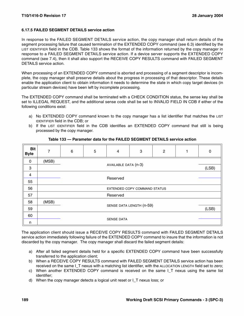
T10/1416-D Revision 17 28 January 2004
6.17.5 FAILED SEGMENT DETAILS service action
In response to the FAILED SEGMENT DETAILS service action, the copy manager shall return details of thesegment processing failure that caused termination of the EXTENDED COPY command (see 6.3) identified by theLIST IDENTIFIER field in the CDB. Table 133 shows the format of the information returned by the copy manager inresponse to a FAILED SEGMENT DETAILS service action. If a device server supports the EXTENDED COPYcommand (see 7.4), then it shall also support the RECEIVE COPY RESULTS command with FAILED SEGMENTDETAILS service action.
When processing of an EXTENDED COPY command is aborted and processing of a segment descriptor is incom-plete, the copy manager shall preserve details about the progress in processing of that descriptor. These detailsenable the application client to obtain information it needs to determine the state in which copy target devices (inparticular stream devices) have been left by incomplete processing.
The EXTENDED COPY command shall be terminated with a CHECK CONDITION status, the sense key shall beset to ILLEGAL REQUEST, and the additional sense code shall be set to INVALID FIELD IN CDB if either of thefollowing conditions exist:
a) No EXTENDED COPY command known to the copy manager has a list identifier that matches the LIST
IDENTIFIER field in the CDB; orb) If the LIST IDENTIFIER field in the CDB identifies an EXTENDED COPY command that still is being
processed by the copy manager.
The application client should issue a RECEIVE COPY RESULTS command with FAILED SEGMENT DETAILSservice action immediately following failure of the EXTENDED COPY command to insure that the information is notdiscarded by the copy manager. The copy manager shall discard the failed segment details:
a) After all failed segment details held for a specific EXTENDED COPY command have been successfullytransferred to the application client;
b) When a RECEIVE COPY RESULTS command with FAILED SEGMENT DETAILS service action has beenreceived on the same I_T nexus with a matching list identifier, with the ALLOCATION LENGTH field set to zero;
c) When another EXTENDED COPY command is received on the same I_T nexus using the same listidentifier;
d) When the copy manager detects a logical unit reset or I_T nexus loss; or
Table 133 — Parameter data for the FAILED SEGMENT DETAILS service action
BitByte
7 6 5 4 3 2 1 0
0 (MSB)AVAILABLE DATA (n-3)
3 (LSB)
4Reserved
55
56 EXTENDED COPY COMMAND STATUS
57 Reserved
58 (MSB)SENSE DATA LENGTH (n-59)
59 (LSB)
60SENSE DATA
n
189 Working Draft SCSI Primary Commands - 3 (SPC-3)
28 January 2004 T10/1416-D Revision 17
e) When the copy manager requires the resources used to preserve the data.
The AVAILABLE DATA field shall contain the number of bytes of failed segment details available for delivery to theapplication client. If the amount of failed segment details data sent to the application client is reduced due to insuf-ficient allocation length, the AVAILABLE DATA field shall not be altered and the failed segment details shall not bediscarded. If no failed segment details data is available for the specified list identifier then the AVAILABLE DATA fieldshall be set to zero and no data beyond the AVAILABLE DATA field shall be returned.
The COPY COMMAND STATUS field contains the SCSI status value that was returned for the EXTENDED COPYcommand identified by the LIST IDENTIFIER field in the CDB.
The SENSE DATA LENGTH field indicates how many bytes of sense data are present in the SENSE DATA field.
The SENSE DATA field contains a copy of the sense data that the copy manager prepared as part of terminating theEXTENDED COPY command identified by the list identifier with a CHECK CONDITION status.
NOTE 30 - Specific uses of the reserved bytes 4 to 55 are under discussion for SPC-3.
Working Draft SCSI Primary Commands - 3 (SPC-3) 190
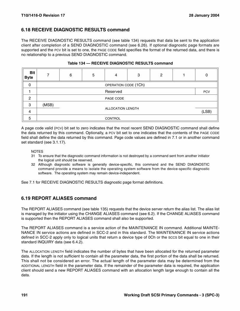
T10/1416-D Revision 17 28 January 2004
6.18 RECEIVE DIAGNOSTIC RESULTS command
The RECEIVE DIAGNOSTIC RESULTS command (see table 134) requests that data be sent to the applicationclient after completion of a SEND DIAGNOSTIC command (see 6.26). If optional diagnostic page formats aresupported and the PCV bit is set to one, the PAGE CODE field specifies the format of the returned data, and there isno relationship to a previous SEND DIAGNOSTIC command.
A page code valid (PCV) bit set to zero indicates that the most recent SEND DIAGNOSTIC command shall definethe data returned by this command. Optionally, a PCV bit set to one indicates that the contents of the PAGE CODE
field shall define the data returned by this command. Page code values are defined in 7.1 or in another commandset standard (see 3.1.17).
NOTES31 To ensure that the diagnostic command information is not destroyed by a command sent from another initiator
the logical unit should be reserved.32 Although diagnostic software is generally device-specific, this command and the SEND DIAGNOSTIC
command provide a means to isolate the operating system software from the device-specific diagnosticsoftware. The operating system may remain device-independent.
See 7.1 for RECEIVE DIAGNOSTIC RESULTS diagnostic page format definitions.
6.19 REPORT ALIASES command
The REPORT ALIASES command (see table 135) requests that the device server return the alias list. The alias listis managed by the initiator using the CHANGE ALIASES command (see 6.2). If the CHANGE ALIASES commandis supported then the REPORT ALIASES command shall also be supported.
The REPORT ALIASES command is a service action of the MAINTENANCE IN command. Additional MAINTE-NANCE IN service actions are defined in SCC-2 and in this standard. The MAINTENANCE IN service actionsdefined in SCC-2 apply only to logical units that return a device type of 0Ch or the SCCS bit equal to one in theirstandard INQUIRY data (see 6.4.2).
The ALLOCATION LENGTH field indicates the number of bytes that have been allocated for the returned parameterdata. If the length is not sufficient to contain all the parameter data, the first portion of the data shall be returned.This shall not be considered an error. The actual length of the parameter data may be determined from theADDITIONAL LENGTH field in the parameter data. If the remainder of the parameter data is required, the applicationclient should send a new REPORT ALIASES command with an allocation length large enough to contain all thedata.
Table 134 — RECEIVE DIAGNOSTIC RESULTS command
BitByte
7 6 5 4 3 2 1 0
0 OPERATION CODE (1Ch)
1 Reserved PCV
2 PAGE CODE
3 (MSB)ALLOCATION LENGTH
4 (LSB)
5 CONTROL
191 Working Draft SCSI Primary Commands - 3 (SPC-3)
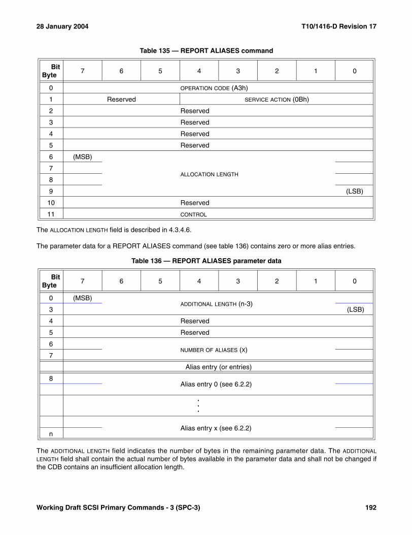
28 January 2004 T10/1416-D Revision 17
The ALLOCATION LENGTH field is described in 4.3.4.6.
The parameter data for a REPORT ALIASES command (see table 136) contains zero or more alias entries.
The ADDITIONAL LENGTH field indicates the number of bytes in the remaining parameter data. The ADDITIONAL
LENGTH field shall contain the actual number of bytes available in the parameter data and shall not be changed ifthe CDB contains an insufficient allocation length.
Table 135 — REPORT ALIASES command
BitByte
7 6 5 4 3 2 1 0
0 OPERATION CODE (A3h)
1 Reserved SERVICE ACTION (0Bh)
2 Reserved
3 Reserved
4 Reserved
5 Reserved
6 (MSB)
ALLOCATION LENGTH7
8
9 (LSB)
10 Reserved
11 CONTROL
Table 136 — REPORT ALIASES parameter data
BitByte
7 6 5 4 3 2 1 0
0 (MSB)ADDITIONAL LENGTH (n-3)
3 (LSB)
4 Reserved
5 Reserved
6NUMBER OF ALIASES (X)
7
Alias entry (or entries)
8Alias entry 0 (see 6.2.2)
.
.
.
Alias entry x (see 6.2.2)n
Working Draft SCSI Primary Commands - 3 (SPC-3) 192

T10/1416-D Revision 17 28 January 2004
The NUMBER OF ALIASES field indicates the number of alias entries in the alias list and shall not be changed if theCDB contains an insufficient allocation length.
The parameter data shall include one alias entry for each alias in the alias list. The format of an alias entry isdescribed in 6.2.2.
6.20 REPORT DEVICE IDENTIFIER command
The REPORT DEVICE IDENTIFIER command (see table 137) requests that the device server send device identifi-cation information to the application client. As defined in the SCC-2 standard, the REPORT DEVICE IDENTIFIERcommand is the REPORT PERIPHERAL DEVICE/COMPONENT DEVICE IDENTIFIER service action of theMAINTENANCE IN command. Additional MAINTENANCE IN and MAINTENANCE OUT service actions aredefined in SCC-2 and in this standard.
The MAINTENANCE IN service actions defined only in SCC-2 shall apply only to SCSI devices that return a devicetype of 0Ch or the SCCS bit equal to one in their standard INQUIRY data. When a SCSI device returns a device typeof 0Ch or the SCCS bit equal to one in its standard INQUIRY data, the implementation requirements for the SCC-2MAINTENANCE IN service actions shall be as specified in SCC-2. Otherwise the MAINTENANCE IN serviceaction definitions and implementation requirements stated in this standard shall apply.
SCC-2 defines specific usages for bytes 4 and 5, and bit 1 in byte 10, however these fields are reserved for theREPORT DEVICE IDENTIFIER command defined by this standard.
The ALLOCATION LENGTH field indicates how many bytes have been allocated for the returned parameter data. If thelength is not sufficient to contain all the parameter data, the first portion of the data shall be returned. This shall notbe considered an error. The actual length of the parameter data is available in the IDENTIFIER LENGTH field in theparameter data. If the remainder of the parameter data is required, the application client should send a newREPORT DEVICE IDENTIFIER command with an ALLOCATION LENGTH field large enough to contain all the data.
Table 137 — REPORT DEVICE IDENTIFIER command
BitByte
7 6 5 4 3 2 1 0
0 OPERATION CODE (A3h)
1 Reserved SERVICE ACTION (05h)
2 Reserved
3 Reserved
4Restricted
5
6 (MSB)
ALLOCATION LENGTH7
8
9 (LSB)
10 Reserved Restricted Reserved
11 CONTROL
193 Working Draft SCSI Primary Commands - 3 (SPC-3)
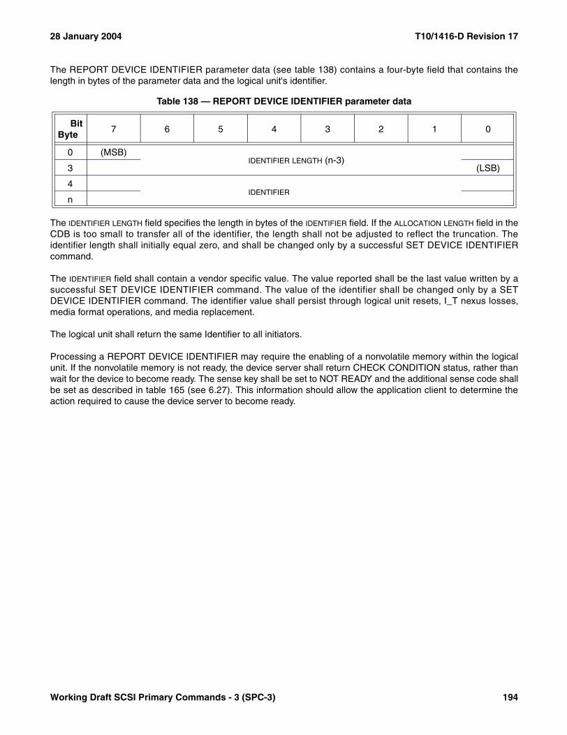
28 January 2004 T10/1416-D Revision 17
The REPORT DEVICE IDENTIFIER parameter data (see table 138) contains a four-byte field that contains thelength in bytes of the parameter data and the logical unit's identifier.
The IDENTIFIER LENGTH field specifies the length in bytes of the IDENTIFIER field. If the ALLOCATION LENGTH field in theCDB is too small to transfer all of the identifier, the length shall not be adjusted to reflect the truncation. Theidentifier length shall initially equal zero, and shall be changed only by a successful SET DEVICE IDENTIFIERcommand.
The IDENTIFIER field shall contain a vendor specific value. The value reported shall be the last value written by asuccessful SET DEVICE IDENTIFIER command. The value of the identifier shall be changed only by a SETDEVICE IDENTIFIER command. The identifier value shall persist through logical unit resets, I_T nexus losses,media format operations, and media replacement.
The logical unit shall return the same Identifier to all initiators.
Processing a REPORT DEVICE IDENTIFIER may require the enabling of a nonvolatile memory within the logicalunit. If the nonvolatile memory is not ready, the device server shall return CHECK CONDITION status, rather thanwait for the device to become ready. The sense key shall be set to NOT READY and the additional sense code shallbe set as described in table 165 (see 6.27). This information should allow the application client to determine theaction required to cause the device server to become ready.
Table 138 — REPORT DEVICE IDENTIFIER parameter data
BitByte
7 6 5 4 3 2 1 0
0 (MSB)IDENTIFIER LENGTH (n-3)
3 (LSB)
4IDENTIFIER
n
Working Draft SCSI Primary Commands - 3 (SPC-3) 194
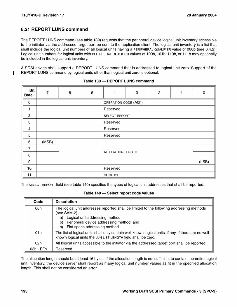
T10/1416-D Revision 17 28 January 2004
6.21 REPORT LUNS command
The REPORT LUNS command (see table 139) requests that the peripheral device logical unit inventory accessibleto the initiator via the addressed target port be sent to the application client. The logical unit inventory is a list thatshall include the logical unit numbers of all logical units having a PERIPHERAL QUALIFIER value of 000b (see 6.4.2).Logical unit numbers for logical units with PERIPHERAL QUALIFIER values of 100b, 101b, 110b, or 111b may optionallybe included in the logical unit inventory.
A SCSI device shall support a REPORT LUNS command that is addressed to logical unit zero. Support of theREPORT LUNS command by logical units other than logical unit zero is optional.
The SELECT REPORT field (see table 140) specifies the types of logical unit addresses that shall be reported.
The allocation length should be at least 16 bytes. If the allocation length is not sufficient to contain the entire logicalunit inventory, the device server shall report as many logical unit number values as fit in the specified allocationlength. This shall not be considered an error.
Table 139 — REPORT LUNS command
BitByte
7 6 5 4 3 2 1 0
0 OPERATION CODE (A0h)
1 Reserved
2 SELECT REPORT
3 Reserved
4 Reserved
5 Reserved
6 (MSB)
ALLOCATION LENGTH7
8
9 (LSB)
10 Reserved
11 CONTROL
Table 140 — Select report code values
Code Description
00h The logical unit addresses reported shall be limited to the following addressing methods (see SAM-2):
a) Logical unit addressing method,b) Peripheral device addressing method; andc) Flat space addressing method.
01h The list of logical units shall only contain well known logical units, if any. If there are no well known logical units the LUN LIST LENGTH field shall be zero.
02h All logical units accessible to the initiator via the addressed target port shall be reported.
03h - FFh Reserved
195 Working Draft SCSI Primary Commands - 3 (SPC-3)
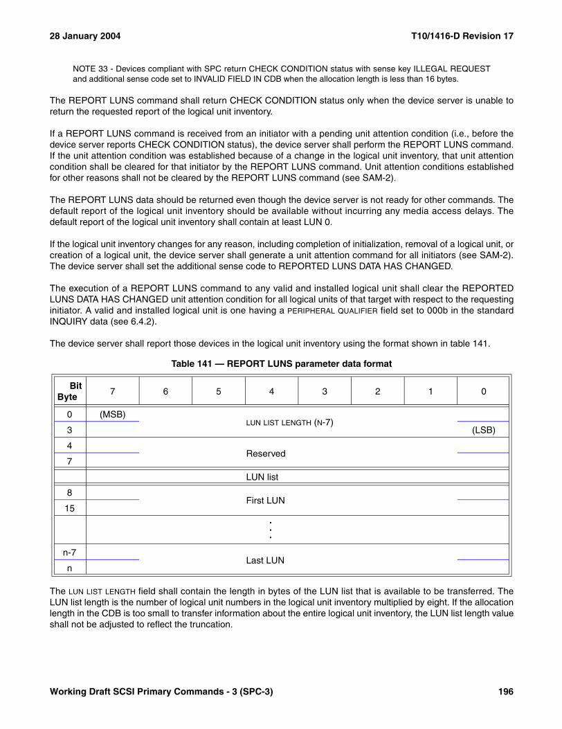
28 January 2004 T10/1416-D Revision 17
NOTE 33 - Devices compliant with SPC return CHECK CONDITION status with sense key ILLEGAL REQUESTand additional sense code set to INVALID FIELD IN CDB when the allocation length is less than 16 bytes.
The REPORT LUNS command shall return CHECK CONDITION status only when the device server is unable toreturn the requested report of the logical unit inventory.
If a REPORT LUNS command is received from an initiator with a pending unit attention condition (i.e., before thedevice server reports CHECK CONDITION status), the device server shall perform the REPORT LUNS command.If the unit attention condition was established because of a change in the logical unit inventory, that unit attentioncondition shall be cleared for that initiator by the REPORT LUNS command. Unit attention conditions establishedfor other reasons shall not be cleared by the REPORT LUNS command (see SAM-2).
The REPORT LUNS data should be returned even though the device server is not ready for other commands. Thedefault report of the logical unit inventory should be available without incurring any media access delays. Thedefault report of the logical unit inventory shall contain at least LUN 0.
If the logical unit inventory changes for any reason, including completion of initialization, removal of a logical unit, orcreation of a logical unit, the device server shall generate a unit attention command for all initiators (see SAM-2).The device server shall set the additional sense code to REPORTED LUNS DATA HAS CHANGED.
The execution of a REPORT LUNS command to any valid and installed logical unit shall clear the REPORTEDLUNS DATA HAS CHANGED unit attention condition for all logical units of that target with respect to the requestinginitiator. A valid and installed logical unit is one having a PERIPHERAL QUALIFIER field set to 000b in the standardINQUIRY data (see 6.4.2).
The device server shall report those devices in the logical unit inventory using the format shown in table 141.
The LUN LIST LENGTH field shall contain the length in bytes of the LUN list that is available to be transferred. TheLUN list length is the number of logical unit numbers in the logical unit inventory multiplied by eight. If the allocationlength in the CDB is too small to transfer information about the entire logical unit inventory, the LUN list length valueshall not be adjusted to reflect the truncation.
Table 141 — REPORT LUNS parameter data format
BitByte
7 6 5 4 3 2 1 0
0 (MSB)LUN LIST LENGTH (N-7)
3 (LSB)
4Reserved
7
LUN list
8First LUN
15...
n-7Last LUN
n
Working Draft SCSI Primary Commands - 3 (SPC-3) 196

T10/1416-D Revision 17 28 January 2004
6.22 REPORT SUPPORTED OPERATION CODES command
6.22.1 REPORT SUPPORTED OPERATION CODES command introduction
The REPORT SUPPORTED OPERATION CODES command (see table 142) requests information on commandsthe addressed logical unit supports. An application client may request a list of all operation codes and serviceactions supported by the logical unit or the command support data for a specific command.
The REPORT SUPPORTED OPERATION CODES command is a service action of the MAINTENANCE INcommand. Additional MAINTENANCE IN service actions are defined in SCC-2 and in this standard. The MAINTE-NANCE IN service actions defined in SCC-2 apply only to logical units that return a device type of 0Ch or the SCCS
bit equal to one in their standard INQUIRY data (see 6.4.2).
Table 142 — REPORT SUPPORTED OPERATION CODES command
BitByte
7 6 5 4 3 2 1 0
0 OPERATION CODE (A3h)
1 Reserved SERVICE ACTION (0Ch)
2 Reserved REPORTING OPTIONS
3 REQUESTED OPERATION CODE
4 (MSB)REQUESTED SERVICE ACTION
5 (LSB)
6 (MSB)
ALLOCATION LENGTH7
8
9 (LSB)
10 Reserved
11 CONTROL
197 Working Draft SCSI Primary Commands - 3 (SPC-3)

28 January 2004 T10/1416-D Revision 17
The REPORTING OPTIONS field (see table 143) specifies the information to be returned in the parameter data.
The REQUESTED OPERATION CODE field specifies the operation code of the command to be returned in theone_command parameter data format (see 6.22.3).
The REQUESTED SERVICE ACTION field specifies the service action of the command to be returned in theone_command parameter data format.
The ALLOCATION LENGTH field specifies the number of bytes that have been allocated for the returned parameterdata. If the length is not sufficient to contain all the parameter data, the first portion of the data shall be returned.This shall not be considered an error. The actual length of the parameter data may be determined from theADDITIONAL LENGTH field in the parameter data. If the remainder of the parameter data is required, the applicationclient should send a new REPORT SUPPORTED OPERATION CODES command with an allocation length largeenough to contain all the data.
Table 143 — REPORT SUPPORTED OPERATION CODES reporting options
Reporting Option Description
Parameter Data Reference
000b A list of all operation codes and service actions supported by the logical unit shall be returned in the all_commands parameter data format. The REQUESTED OPERATION CODE CDB field and REQUESTED SERVICE ACTION CDB field shall be ignored.
6.22.2
001b The command support data for the operation code specified in the REQUESTED OPERATION CODE field shall be returned in the one_command parameter data format. The REQUESTED SERVICE ACTION CDB field shall be ignored. If the REQUESTED OPERATION CODE field specifies an operation code that has service actions the device server shall return CHECK CONDITION status. The sense key shall be set to ILLEGAL REQUEST and the additional sense code shall be set to INVALID FIELD IN CDB.
6.22.3
010b The command support data for the operation code and service action specified in the REQUESTED OPERATION CODE CDB field and REQUESTED SERVICE ACTION CDB field shall be returned in the one_command parameter data format. If the REQUESTED OPERATION CODE CDB field specifies an operation code that does not have service actions the device server shall return CHECK CONDITION status. The sense key shall be set to ILLEGAL REQUEST and the additional sense code shall be set to INVALID FIELD IN CDB.
6.22.3
011b-111b Reserved
Working Draft SCSI Primary Commands - 3 (SPC-3) 198
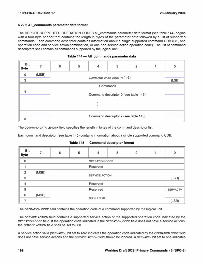
T10/1416-D Revision 17 28 January 2004
6.22.2 All_commands parameter data format
The REPORT SUPPORTED OPERATION CODES all_commands parameter data format (see table 144) beginswith a four-byte header that contains the length in bytes of the parameter data followed by a list of supportedcommands. Each command descriptor contains information about a single supported command CDB (i.e., oneoperation code and service action combination, or one non-service-action operation code). The list of commanddescriptors shall contain all commands supported by the logical unit.
The COMMAND DATA LENGTH field specifies the length in bytes of the command descriptor list.
Each command descriptor (see table 145) contains information about a single supported command CDB.
The OPERATION CODE field contains the operation code of a command supported by the logical unit.
The SERVICE ACTION field contains a supported service action of the supported operation code indicated by theOPERATION CODE field. If the operation code indicated in the OPERATION CODE field does not have a service actions,the SERVICE ACTION field shall be set to 00h.
A service action valid (SERVACTV) bit set to zero indicates the operation code indicated by the OPERATION CODE fielddoes not have service actions and the SERVICE ACTION field should be ignored. A SERVACTV bit set to one indicates
Table 144 — All_commands parameter data
BitByte
7 6 5 4 3 2 1 0
0 (MSB)COMMAND DATA LENGTH (n-3)
3 (LSB)
Commands
4Command descriptor 0 (see table 145)
.
.
.
Command descriptor x (see table 145)n
Table 145 — Command descriptor format
BitByte
7 6 5 4 3 2 1 0
0 OPERATION CODE
1 Reserved
2 (MSB)SERVICE ACTION
3 (LSB)
4 Reserved
5 Reserved SERVACTV
6 (MSB)CDB LENGTH
7 (LSB)
199 Working Draft SCSI Primary Commands - 3 (SPC-3)
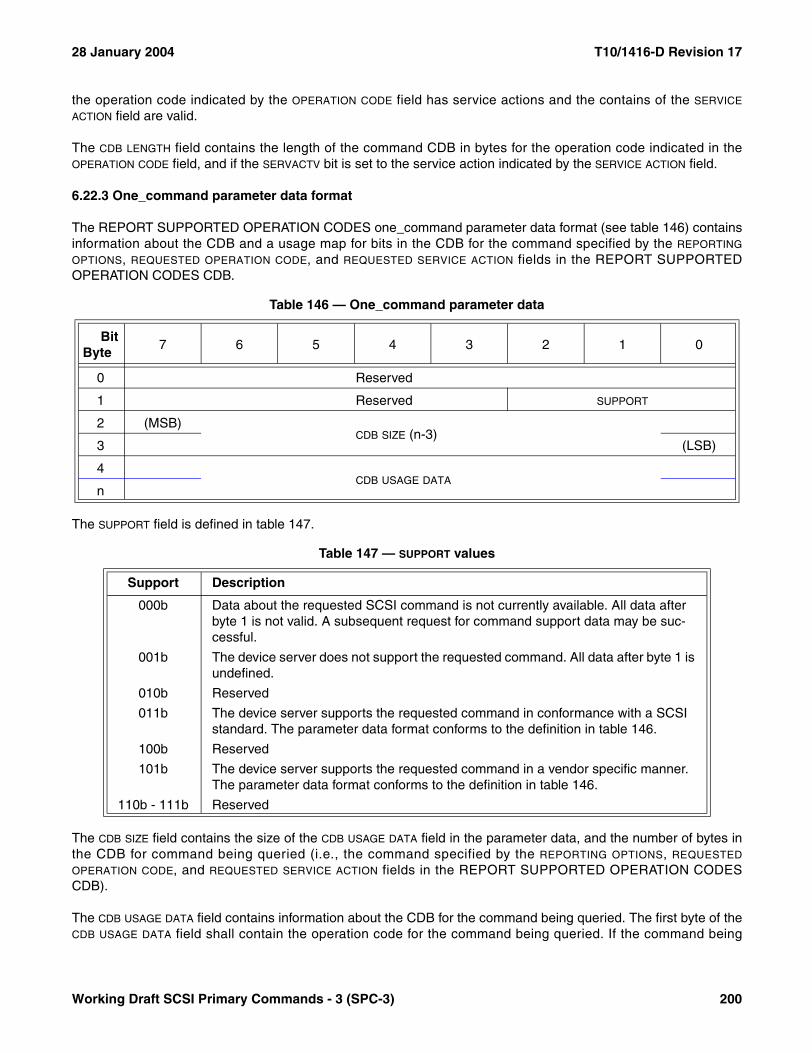
28 January 2004 T10/1416-D Revision 17
the operation code indicated by the OPERATION CODE field has service actions and the contains of the SERVICE
ACTION field are valid.
The CDB LENGTH field contains the length of the command CDB in bytes for the operation code indicated in theOPERATION CODE field, and if the SERVACTV bit is set to the service action indicated by the SERVICE ACTION field.
6.22.3 One_command parameter data format
The REPORT SUPPORTED OPERATION CODES one_command parameter data format (see table 146) containsinformation about the CDB and a usage map for bits in the CDB for the command specified by the REPORTING
OPTIONS, REQUESTED OPERATION CODE, and REQUESTED SERVICE ACTION fields in the REPORT SUPPORTEDOPERATION CODES CDB.
The SUPPORT field is defined in table 147.
The CDB SIZE field contains the size of the CDB USAGE DATA field in the parameter data, and the number of bytes inthe CDB for command being queried (i.e., the command specified by the REPORTING OPTIONS, REQUESTED
OPERATION CODE, and REQUESTED SERVICE ACTION fields in the REPORT SUPPORTED OPERATION CODESCDB).
The CDB USAGE DATA field contains information about the CDB for the command being queried. The first byte of theCDB USAGE DATA field shall contain the operation code for the command being queried. If the command being
Table 146 — One_command parameter data
BitByte
7 6 5 4 3 2 1 0
0 Reserved
1 Reserved SUPPORT
2 (MSB)CDB SIZE (n-3)
3 (LSB)
4CDB USAGE DATA
n
Table 147 — SUPPORT values
Support Description
000b Data about the requested SCSI command is not currently available. All data after byte 1 is not valid. A subsequent request for command support data may be suc-cessful.
001b The device server does not support the requested command. All data after byte 1 is undefined.
010b Reserved
011b The device server supports the requested command in conformance with a SCSI standard. The parameter data format conforms to the definition in table 146.
100b Reserved
101b The device server supports the requested command in a vendor specific manner. The parameter data format conforms to the definition in table 146.
110b - 111b Reserved
Working Draft SCSI Primary Commands - 3 (SPC-3) 200

T10/1416-D Revision 17 28 January 2004
queried contains a service action, then that service action code shall be placed the CDB USAGE DATA field in thesame location as the SERVICE ACTION field of the command CDB. All other bytes of the CDB USAGE DATA field shallcontain a usage map for bits in the CDB for the command being queried.
The bits in the usage map shall have a one-for-one correspondence to the CDB for the command being queried. Ifthe device server evaluates a bit in the CDB for the command being queried, the usage map shall contain a one inthe corresponding bit position. If any bit representing part of a field is returned as one, all bits for the field shall bereturned as one. If the device server ignores or treats as reserved a bit in the CDB for the command being queried,the usage map shall contain a zero in the corresponding bit position. The usage map bits for a given CDB field allshall have the same value.
For example, the CDB usage bit map for the REPORT SUPPORTED OPERATION CODES command is: A3h,0Ch, 03h, FFh, FFh, FFh, FFh, FFh, FFh, FFh, 00h, 07h. This example assumes that the logical unit only supportsthe low-order three bits of the CONTROL byte. The first byte contains the operation code, and the second bytecontains three reserved bits and the service action. The remaining bytes contain the usage map.
6.23 REPORT SUPPORTED TASK MANAGEMENT FUNCTIONS command
The REPORT SUPPORTED TASK MANAGEMENT FUNCTIONS command (see table 148) requests informationon task management functions (see SAM-3) the addressed logical unit supports.
The REPORT SUPPORTED TASK MANAGEMENT FUNCTIONS command is a service action of the MAINTE-NANCE IN command. Additional MAINTENANCE IN service actions are defined in SCC-2 and in this standard.The MAINTENANCE IN service actions defined in SCC-2 apply only to logical units that return a device type of0Ch or the SCCS bit equal to one in their standard INQUIRY data (see 6.4.2).
The ALLOCATION LENGTH field indicates the number of bytes that have been allocated for the returned parameterdata. The allocation length shall be at least four. If the allocation length is less than for the command shall be termi-nated with a CHECK CONDITION status, the sense key shall be set to ILLEGAL REQUEST, and the additionalsense code shall be set to INVALID FIELD IN CDB.
Table 148 — REPORT SUPPORTED TASK MANAGEMENT FUNCTIONS command
BitByte
7 6 5 4 3 2 1 0
0 OPERATION CODE (A3h)
1 Reserved SERVICE ACTION (0Dh)
2Reserved
5
6 (MSB)ALLOCATION LENGTH (4h or larger)
9 (LSB)
10 Reserved
11 CONTROL
201 Working Draft SCSI Primary Commands - 3 (SPC-3)

28 January 2004 T10/1416-D Revision 17
The format of the parameter data returned by the REPORT TASK MANAGEMENT FUNCTIONS command isshown in table 149.
An ABORT TASK supported (ATS) bit set to one indicates the ABORT TASK task management function issupported by the logical unit. An ATS bit set to zero indicates the ABORT TASK task management function is notsupported.
An ABORT TASK SET supported (ATSS) bit set to one indicates the ABORT TASK SET task management functionis supported by the logical unit. An ATSS bit set to zero indicates the ABORT TASK SET task management functionis not supported.
A CLEAR ACA supported (CACAS) bit set to one indicates the CLEAR ACA task management function is supportedby the logical unit. An CACAS bit set to zero indicates the CLEAR ACA task management function is not supported.
A CLEAR TASK SET supported (CTSS) bit set to one indicates the CLEAR TASK SET task management function issupported by the logical unit. An CTSS bit set to zero indicates the CLEAR TASK SET task management function isnot supported.
A LOGICAL UNIT RESET supported (LURS) bit set to one indicates the LOGICAL UNIT RESET task managementfunction is supported by the logical unit. An LURS bit set to zero indicates the LOGICAL UNIT RESET taskmanagement function is not supported.
A QUERY TASK supported (QTS) bit set to one indicates the QUERY TASK task management function is supportedby the logical unit. An QTS bit set to zero indicates the QUERY TASK task management function is not supported.
A TARGET RESET supported (TRS) bit set to one indicates the TARGET RESET task management function (seeSAM-2) is supported by the logical unit. An TRS bit set to zero indicates the TARGET RESET task managementfunction is not supported.
A WAKEUP supported (WAKES) bit set to one indicates the WAKEUP task management function is supported bythe logical unit. An WAKES bit set to zero indicates the WAKEUP task management function is not supported.
Table 149 — REPORT SUPPORTED TASK MANAGEMENT FUNCTIONS parameter data
BitByte
7 6 5 4 3 2 1 0
0 ATS ATSS CACAS CTSS LURS QTS TRS WAKES
1Reserved
3
Working Draft SCSI Primary Commands - 3 (SPC-3) 202
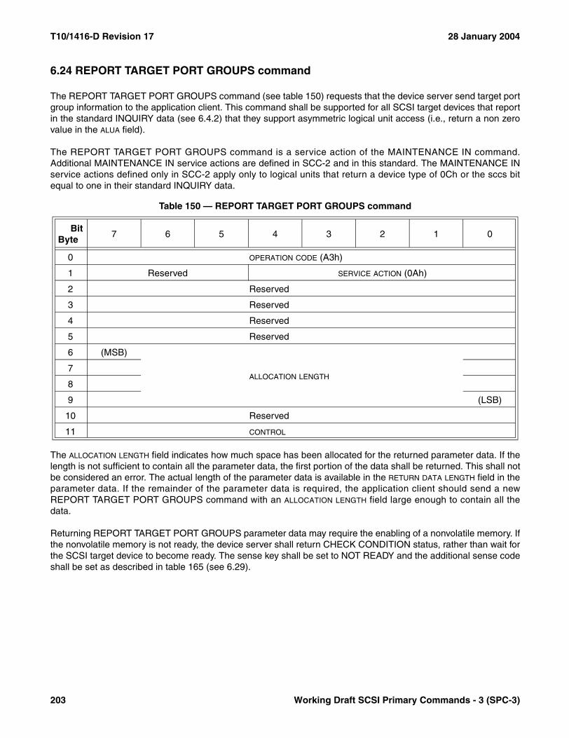
T10/1416-D Revision 17 28 January 2004
6.24 REPORT TARGET PORT GROUPS command
The REPORT TARGET PORT GROUPS command (see table 150) requests that the device server send target portgroup information to the application client. This command shall be supported for all SCSI target devices that reportin the standard INQUIRY data (see 6.4.2) that they support asymmetric logical unit access (i.e., return a non zerovalue in the ALUA field).
The REPORT TARGET PORT GROUPS command is a service action of the MAINTENANCE IN command.Additional MAINTENANCE IN service actions are defined in SCC-2 and in this standard. The MAINTENANCE INservice actions defined only in SCC-2 apply only to logical units that return a device type of 0Ch or the sccs bitequal to one in their standard INQUIRY data.
The ALLOCATION LENGTH field indicates how much space has been allocated for the returned parameter data. If thelength is not sufficient to contain all the parameter data, the first portion of the data shall be returned. This shall notbe considered an error. The actual length of the parameter data is available in the RETURN DATA LENGTH field in theparameter data. If the remainder of the parameter data is required, the application client should send a newREPORT TARGET PORT GROUPS command with an ALLOCATION LENGTH field large enough to contain all thedata.
Returning REPORT TARGET PORT GROUPS parameter data may require the enabling of a nonvolatile memory. Ifthe nonvolatile memory is not ready, the device server shall return CHECK CONDITION status, rather than wait forthe SCSI target device to become ready. The sense key shall be set to NOT READY and the additional sense codeshall be set as described in table 165 (see 6.29).
Table 150 — REPORT TARGET PORT GROUPS command
BitByte
7 6 5 4 3 2 1 0
0 OPERATION CODE (A3h)
1 Reserved SERVICE ACTION (0Ah)
2 Reserved
3 Reserved
4 Reserved
5 Reserved
6 (MSB)
ALLOCATION LENGTH7
8
9 (LSB)
10 Reserved
11 CONTROL
203 Working Draft SCSI Primary Commands - 3 (SPC-3)

28 January 2004 T10/1416-D Revision 17
The format for the parameter data returned by the REPORT TARGET PORT GROUPS command is shown in table151.
The RETURN DATA LENGTH field specifies the length in bytes of the list of target port groups. If the allocation length inthe CDB is too small to transfer all of the descriptors, the RETURN DATA LENGTH field shall not be adjusted to reflectthe truncation.
There shall be one target port group descriptor (see table 152) for each target port group.
Table 151 — REPORT TARGET PORT GROUPS parameter data format
BitByte
7 6 5 4 3 2 1 0
0 (MSB)RETURN DATA LENGTH (n-3)
3 (LSB)
Target port group descriptor(s)
4Target port group descriptor 0 (see table 152)
.
.
.
Target port group descriptor x (see table 152)n
Table 152 — Target port group descriptor parameter data
BitByte
7 6 5 4 3 2 1 0
0 Reserved ASYMMETRIC ACCESS STATE
1 Reserved U_SUP S_SUP AN_SUP AO_SUP
2 (MSB)TARGET PORT GROUP
3 (LSB)
4 Reserved
5 STATUS CODE
6 Vendor unique
7 TARGET PORT COUNT (x)
Relative target port(s)
8RELATIVE TARGET PORT 1
11...
n-3RELATIVE TARGET PORT x
n
Working Draft SCSI Primary Commands - 3 (SPC-3) 204

T10/1416-D Revision 17 28 January 2004
The ASYMMETRIC ACCESS STATE field (see table 153) contains the target port group’s current asymmetric accessstate (see 5.8.4).
If any of the U_SUP bit, S_SUP bit, AN_SUP bit, or AO_SUP bit is set to one, then the U_SUP bit, S_SUP bit, AN_SUP bit,and AO_SUP bit are as defined in this standard. If the U_SUP bit, S_SUP bit, AN_SUP bit, or AO_SUP bit are all set tozero, the bits are reserved as defined by previous versions of this standard.
A U_SUP bit set to one indicates that the unavailable asymmetric access state is supported. A U_SUP bit set to zeroindicates that the unavailable asymmetric access state is not supported.
An S_SUP bit set to one indicates that the standby asymmetric access state is supported. An S_SUP bit set to zeroindicates that the standby asymmetric access state is not supported.
An AN_SUP bit set to one indicates that the active/non-optimized asymmetric access state is supported. An AN_SUP
bit set to zero indicates that the active/non-optimized asymmetric access state is not supported.
An AO_SUP bit set to one indicates that the active/optimized asymmetric access state is supported. An AO_SUP bitset to zero indicates that the active/optimized asymmetric access state is not supported.
The TARGET PORT GROUP field contains an identification of the target port group described by this target port groupdescriptor.
The STATUS CODE field (see table 154) indicates why a target port group may be in a specific target port groupasymmetric access state. It provides a mechanism to indicate error conditions.
The TARGET PORT COUNT field indicates the number of target ports that are in that target port group. Every targetport group shall contain at least one target port.
For each target port in the target port group one RELATIVE TARGET PORT field contains an identification of that targetport using the value returned by identifier type 4h in the Device Identification VPD page (see 7.6.4). The target portdescriptor shall include exactly one RELATIVE TARGET PORT field for each target port in the target port group.
Table 153 — Asymmetric access state
Value State
0h Active/optimized
1h Active/non-optimized
2h Standby
3h Unavailable
4h-Eh Reserved
Fh Transitioning between states
Table 154 — STATUS CODE field
Value Description
00h No status available.
01h Target port group asymmetric access state changed by SET TARGET PORT GROUPS command.
02h Target port group asymmetric access state changed by implicit asymmetrical logical unit access behavior.
03h-FFh Reserved
205 Working Draft SCSI Primary Commands - 3 (SPC-3)
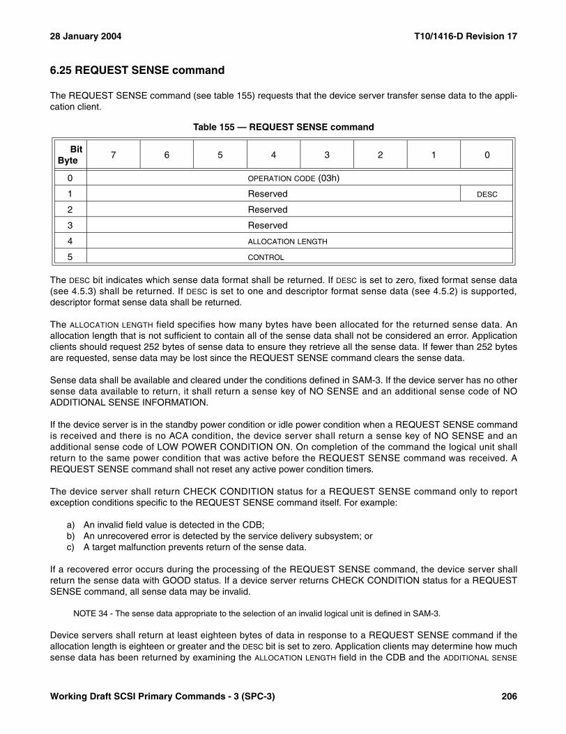
28 January 2004 T10/1416-D Revision 17
6.25 REQUEST SENSE command
The REQUEST SENSE command (see table 155) requests that the device server transfer sense data to the appli-cation client.
The DESC bit indicates which sense data format shall be returned. If DESC is set to zero, fixed format sense data(see 4.5.3) shall be returned. If DESC is set to one and descriptor format sense data (see 4.5.2) is supported,descriptor format sense data shall be returned.
The ALLOCATION LENGTH field specifies how many bytes have been allocated for the returned sense data. Anallocation length that is not sufficient to contain all of the sense data shall not be considered an error. Applicationclients should request 252 bytes of sense data to ensure they retrieve all the sense data. If fewer than 252 bytesare requested, sense data may be lost since the REQUEST SENSE command clears the sense data.
Sense data shall be available and cleared under the conditions defined in SAM-3. If the device server has no othersense data available to return, it shall return a sense key of NO SENSE and an additional sense code of NOADDITIONAL SENSE INFORMATION.
If the device server is in the standby power condition or idle power condition when a REQUEST SENSE commandis received and there is no ACA condition, the device server shall return a sense key of NO SENSE and anadditional sense code of LOW POWER CONDITION ON. On completion of the command the logical unit shallreturn to the same power condition that was active before the REQUEST SENSE command was received. AREQUEST SENSE command shall not reset any active power condition timers.
The device server shall return CHECK CONDITION status for a REQUEST SENSE command only to reportexception conditions specific to the REQUEST SENSE command itself. For example:
a) An invalid field value is detected in the CDB;b) An unrecovered error is detected by the service delivery subsystem; orc) A target malfunction prevents return of the sense data.
If a recovered error occurs during the processing of the REQUEST SENSE command, the device server shallreturn the sense data with GOOD status. If a device server returns CHECK CONDITION status for a REQUESTSENSE command, all sense data may be invalid.
NOTE 34 - The sense data appropriate to the selection of an invalid logical unit is defined in SAM-3.
Device servers shall return at least eighteen bytes of data in response to a REQUEST SENSE command if theallocation length is eighteen or greater and the DESC bit is set to zero. Application clients may determine how muchsense data has been returned by examining the ALLOCATION LENGTH field in the CDB and the ADDITIONAL SENSE
Table 155 — REQUEST SENSE command
BitByte
7 6 5 4 3 2 1 0
0 OPERATION CODE (03h)
1 Reserved DESC
2 Reserved
3 Reserved
4 ALLOCATION LENGTH
5 CONTROL
Working Draft SCSI Primary Commands - 3 (SPC-3) 206

T10/1416-D Revision 17 28 January 2004
LENGTH field in the sense data. Device servers shall not adjust the additional sense length to reflect truncation if theallocation length is less than the sense data available.
207 Working Draft SCSI Primary Commands - 3 (SPC-3)

28 January 2004 T10/1416-D Revision 17
6.26 SEND DIAGNOSTIC command
The SEND DIAGNOSTIC command (see table 156) requests the device server to perform diagnostic operations onthe target, on the logical unit, or on both. Targets that support this command shall implement, at a minimum, thedefault self-test feature (i.e., the SELFTEST bit equal to one and a parameter list length of zero). When the SELFTEST
bit is set to zero and the SELF-TEST CODE field contains 000b, this command is usually followed by a RECEIVEDIAGNOSTIC RESULTS (see 6.18) command.
If the SELFTEST bit is set to one, the SELF-TEST CODE field shall contain 000b. If the SELFTEST bit is set to zero, thecontents of SELF-TEST CODE field are specified in table 157.
Table 156 — SEND DIAGNOSTIC command
BitByte
7 6 5 4 3 2 1 0
0 OPERATION CODE (1Dh)
1 SELF-TEST CODE PF Reserved SELFTEST DEVOFFL UNITOFFL
2 Reserved
3 (MSB)PARAMETER LIST LENGTH
4 (LSB)
5 CONTROL
Table 157 — SELF-TEST CODE field values
Value Name Description
000b This value shall be used when the SELFTEST bit is set to one, or when the SELFTEST bit is set to zero and the PF bit is set to one invoking a page format SEND DIAGNOSTIC function such as enclosure services (see SES) or the Translate Address diagnostic page (see SBC).
001b Backgroundshort self-test
The device server shall start its short self-test (see 5.5.2) in the background mode (see 5.5.3.2). The PARAMETER LIST LENGTH field shall contain zero.
010b Background extended self-test
The device server shall start its extended self-test (see 5.5.2) in the background mode (see 5.5.3.2). The PARAMETER LIST LENGTH field shall contain zero.
011b Reserved
100b Abort back-ground self-test
The device server shall abort the current self-test running in background mode. The PARAMETER LIST LENGTH field shall contain zero. This value is only valid if a previous SEND DIAGNOSTIC command specified a background self-test func-tion and that self-test has not completed. If either of these conditions is not met, then the device server shall return a CHECK CONDITION status with a sense key of ILLEGAL REQUEST and an additional sense code of INVALID FIELD IN CDB.
101b Foregroundshort self-test
The device server shall start its short self-test (see 5.5.2) in the foreground mode (see 5.5.3.1). The PARAMETER LIST LENGTH field shall contain zero.
110b Foreground extended self-test
The device server shall start its extended self-test (see 5.5.2) in the foreground mode (see 5.5.3.1). The PARAMETER LIST LENGTH field shall contain zero.
111b Reserved
Working Draft SCSI Primary Commands - 3 (SPC-3) 208
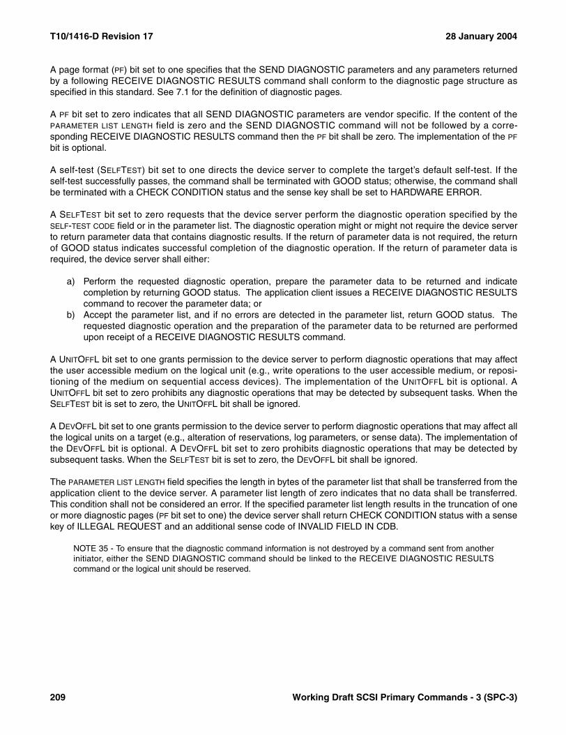
T10/1416-D Revision 17 28 January 2004
A page format (PF) bit set to one specifies that the SEND DIAGNOSTIC parameters and any parameters returnedby a following RECEIVE DIAGNOSTIC RESULTS command shall conform to the diagnostic page structure asspecified in this standard. See 7.1 for the definition of diagnostic pages.
A PF bit set to zero indicates that all SEND DIAGNOSTIC parameters are vendor specific. If the content of thePARAMETER LIST LENGTH field is zero and the SEND DIAGNOSTIC command will not be followed by a corre-sponding RECEIVE DIAGNOSTIC RESULTS command then the PF bit shall be zero. The implementation of the PF
bit is optional.
A self-test (SELFTEST) bit set to one directs the device server to complete the target’s default self-test. If theself-test successfully passes, the command shall be terminated with GOOD status; otherwise, the command shallbe terminated with a CHECK CONDITION status and the sense key shall be set to HARDWARE ERROR.
A SELFTEST bit set to zero requests that the device server perform the diagnostic operation specified by theSELF-TEST CODE field or in the parameter list. The diagnostic operation might or might not require the device serverto return parameter data that contains diagnostic results. If the return of parameter data is not required, the returnof GOOD status indicates successful completion of the diagnostic operation. If the return of parameter data isrequired, the device server shall either:
a) Perform the requested diagnostic operation, prepare the parameter data to be returned and indicatecompletion by returning GOOD status. The application client issues a RECEIVE DIAGNOSTIC RESULTScommand to recover the parameter data; or
b) Accept the parameter list, and if no errors are detected in the parameter list, return GOOD status. Therequested diagnostic operation and the preparation of the parameter data to be returned are performedupon receipt of a RECEIVE DIAGNOSTIC RESULTS command.
A UNITOFFL bit set to one grants permission to the device server to perform diagnostic operations that may affectthe user accessible medium on the logical unit (e.g., write operations to the user accessible medium, or reposi-tioning of the medium on sequential access devices). The implementation of the UNITOFFL bit is optional. AUNITOFFL bit set to zero prohibits any diagnostic operations that may be detected by subsequent tasks. When theSELFTEST bit is set to zero, the UNITOFFL bit shall be ignored.
A DEVOFFL bit set to one grants permission to the device server to perform diagnostic operations that may affect allthe logical units on a target (e.g., alteration of reservations, log parameters, or sense data). The implementation ofthe DEVOFFL bit is optional. A DEVOFFL bit set to zero prohibits diagnostic operations that may be detected bysubsequent tasks. When the SELFTEST bit is set to zero, the DEVOFFL bit shall be ignored.
The PARAMETER LIST LENGTH field specifies the length in bytes of the parameter list that shall be transferred from theapplication client to the device server. A parameter list length of zero indicates that no data shall be transferred.This condition shall not be considered an error. If the specified parameter list length results in the truncation of oneor more diagnostic pages (PF bit set to one) the device server shall return CHECK CONDITION status with a sensekey of ILLEGAL REQUEST and an additional sense code of INVALID FIELD IN CDB.
NOTE 35 - To ensure that the diagnostic command information is not destroyed by a command sent from anotherinitiator, either the SEND DIAGNOSTIC command should be linked to the RECEIVE DIAGNOSTIC RESULTScommand or the logical unit should be reserved.
209 Working Draft SCSI Primary Commands - 3 (SPC-3)

28 January 2004 T10/1416-D Revision 17
6.27 SET DEVICE IDENTIFIER command
The SET DEVICE IDENTIFIER command (see table 158) requests that the device identifier information in thelogical unit be set to the value received in the SET DEVICE IDENTIFIER parameter list. As defined in the SCC-2standard, the SET DEVICE IDENTIFIER command is the SET PERIPHERAL DEVICE/COMPONENT DEVICEIDENTIFIER service action of the MAINTENANCE OUT command. Additional MAINTENANCE IN and MAINTE-NANCE OUT service actions are defined in SCC-2 and in this standard.
The MAINTENANCE OUT service actions defined only in SCC-2 shall apply only to SCSI devices that return adevice type of 0Ch or the SCCS bit equal to one in their standard INQUIRY data. When a SCSI devices returns adevice type of 0Ch or the SCCS bit equal to one in its standard INQUIRY data, the implementation requirements forthe SCC-2 MAINTENANCE OUT service actions shall be as specified in SCC-2. Otherwise the MAINTENANCEOUT service action definitions and implementation requirements stated in this standard shall apply.
On successful completion of a SET DEVICE IDENTIFIER command that changes the device identifier saved by thedevice, a unit attention shall be generated for all initiators except the one that issued the service action. Whenreporting the unit attention condition the additional sense code shall be set to DEVICE IDENTIFIER CHANGED.
SCC-2 defines specific usages for bytes 4 and 5, and bit 1 in byte 10, however these fields are reserved for theSET DEVICE IDENTIFIER command defined by this standard.
The PARAMETER LIST LENGTH field specifies the length in bytes of the identifier that shall be transferred from theapplication client to the device server. The maximum value for this field shall be 512 bytes. A parameter list lengthof zero indicates that no data shall be transferred, and that subsequent REPORT DEVICE IDENTIFIER commandsshall return an Identifier length of zero. Logical units that implement this command shall be capable of accepting aparameter list length of 64 bytes or less. If the parameter list length exceeds 64 bytes and the logical unit is notcapable of storing the requested number of bytes, then the device server shall return CHECK CONDITION statuswith the sense key set to ILLEGAL REQUEST and an additional sense code of INVALID FIELD IN CDB.
Table 158 — SET DEVICE IDENTIFIER command
BitByte
7 6 5 4 3 2 1 0
0 OPERATION CODE (A4h)
1 Reserved SERVICE ACTION (06h)
2 Reserved
3 Reserved
4Restricted
5
6 (MSB)
PARAMETER LIST LENGTH7
8
9 (LSB)
10 Reserved Restricted Reserved
11 CONTROL
Working Draft SCSI Primary Commands - 3 (SPC-3) 210

T10/1416-D Revision 17 28 January 2004
The SET DEVICE IDENTIFIER parameter list (see table 159) contains the identifier to be set by the addressedlogical unit.
The IDENTIFIER field is a value selected by the application client using mechanisms outside the scope of thisstandard to be returned in subsequent REPORT DEVICE IDENTIFIER commands.
6.28 SET TARGET PORT GROUPS command
The SET TARGET PORT GROUPS command (see table 160) requests the device server to set the asymmetricaccess state of all of the target ports in the specified target port groups. See 5.8 for details regarding the transitionbetween target port group asymmetric access states. This command is mandatory for all SCSI target devices thatreport in the standard INQUIRY data (see 6.4.2) that they support explicit asymmetric logical units access (i.e., theALUA field contains either 10b or 11b).
The SET TARGET PORT GROUPS command is a service action of the MAINTENANCE OUT command.Additional MAINTENANCE OUT service actions are defined in SCC-2 and in this standard. The MAINTENANCEOUT service actions defined only in SCC-2 apply only to logical units that return a device type of 0Ch or the sccsbit equal to one in their standard INQUIRY data.
The PARAMETER LIST LENGTH field specifies the length in bytes of the target port group management parametersthat shall be transferred from the application client to the device server. A parameter list length of zero indicatesthat no data shall be transferred, and that no change shall be made in the asymmetric access state of any target
Table 159 — SET DEVICE IDENTIFIER parameter list
BitByte
7 6 5 4 3 2 1 0
0IDENTIFIER
n
Table 160 — SET TARGET PORT GROUPS command
BitByte
7 6 5 4 3 2 1 0
0 OPERATION CODE (A4h)
1 Reserved SERVICE ACTION (0Ah)
2 Reserved
3 Reserved
4 Reserved
5 Reserved
6 (MSB)
PARAMETER LIST LENGTH7
8
9 (LSB)
10 Reserved
11 CONTROL
211 Working Draft SCSI Primary Commands - 3 (SPC-3)
28 January 2004 T10/1416-D Revision 17
port groups. If the parameter list length violates the vendor specific length requirements, then the device servershall return CHECK CONDITION status with the sense key set to ILLEGAL REQUEST and an additional sensecode of INVALID FIELD IN CDB.
The allowable values to which target port asymmetric access states may be set is vendor specific and should bereported in the REPORT TARGET PORT GROUP parameter data (see 6.24).
Target port groups that are not specified in a parameter list may change asymmetric access states as a result ofthe SET TARGET PORT GROUPS command. This shall not be considered an implicit target port groupasymmetric access state change.
If the SET TARGET PORT GROUPS attempts to establish an invalid combination of target port asymmetric accessstates or attempts to establish an unsupported asymmetric access state, the device server shall return CHECKCONDITION status with the sense key set to ILLEGAL REQUEST and an additional sense code of INVALID FIELDIN PARAMETER LIST.
If the SET TARGET PORT GROUPS command has been performed the completion of the command dependsupon which of the following conditions apply:
a) If the transition is treated as a single indivisible event (see 5.8.5), then the SET TARGET PORT GROUPScommand shall not complete until the transition to the requested state has completed; or
b) If the transition is not treated as a single indivisible event (i.e., the device server supports other commands(see 5.8.5) when those commands are routed though a target port that is transitioning betweenasymmetric access states) then the SET TARGET PORT GROUPS command may complete before thetransition into the requested state has completed.
If the SET TARGET PORT GROUPS command is not performed successfully the completion of the commanddepends upon which of the following conditions apply:
a) If the processing of a SET TARGET PORT GROUPS command requires the enabling of a nonvolatilememory and the nonvolatile memory is not ready, then the device server shall return CHECK CONDITIONstatus, rather than wait for the logical unit to become ready. The sense key shall be set to NOT READY andthe additional sense code shall be set as described in table 165 (see 6.29); or
b) If a failure occurred before the transition was completed then the device server shall return CHECKCONDITION status. The sense key shall be set to HARDWARE ERROR and the additional sense codeshall be set to SET TARGET PORT GROUPS COMMAND FAILED.
If two SET TARGET PORT GROUPS commands are performed concurrently, the target port group asymmetricaccess state change behavior is vendor specific. A target should not process multiple SET TARGET PORTGROUPS concurrently.
Working Draft SCSI Primary Commands - 3 (SPC-3) 212
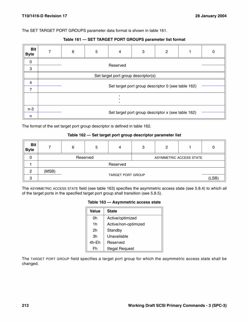
T10/1416-D Revision 17 28 January 2004
The SET TARGET PORT GROUPS parameter data format is shown in table 161.
The format of the set target port group descriptor is defined in table 162.
The ASYMMETRIC ACCESS STATE field (see table 163) specifies the asymmetric access state (see 5.8.4) to which allof the target ports in the specified target port group shall transition (see 5.8.5).
The TARGET PORT GROUP field specifies a target port group for which the asymmetric access state shall bechanged.
Table 161 — SET TARGET PORT GROUPS parameter list format
BitByte
7 6 5 4 3 2 1 0
0Reserved
3
Set target port group descriptor(s)
4Set target port group descriptor 0 (see table 162)
7...
n-3Set target port group descriptor x (see table 162)
n
Table 162 — Set target port group descriptor parameter list
BitByte
7 6 5 4 3 2 1 0
0 Reserved ASYMMETRIC ACCESS STATE
1 Reserved
2 (MSB)TARGET PORT GROUP
3 (LSB)
Table 163 — Asymmetric access state
Value State
0h Active/optimized
1h Active/non-optimized
2h Standby
3h Unavailable
4h-Eh Reserved
Fh Illegal Request
213 Working Draft SCSI Primary Commands - 3 (SPC-3)

28 January 2004 T10/1416-D Revision 17
6.29 TEST UNIT READY command
The TEST UNIT READY command (see table 164) provides a means to check if the logical unit is ready. This is nota request for a self-test. If the logical unit is able to accept an appropriate medium-access command withoutreturning CHECK CONDITION status, this command shall return a GOOD status. If the logical unit is unable tobecome operational or is in a state such that an application client action (e.g., START UNIT command) is requiredto make the unit ready, the device server shall return CHECK CONDITION status with a sense key of NOT READY.
Logical units shall return GOOD status if a reservation conflict is detected.
NOTE 36 - Logical units complying with previous versions of this standard (i.e., SPC-2) may return RESERVATIONCONFLICT rather than GOOD status if a reservation conflict is detected.
Table 165 defines the suggested GOOD and CHECK CONDITION status responses to the TEST UNIT READYcommand. Other conditions, including deferred errors, may result in other responses (e.g., BUSY or RESER-VATION CONFLICT status).
Table 164 — TEST UNIT READY command
BitByte
7 6 5 4 3 2 1 0
0 OPERATION CODE (00h)
1 Reserved
2 Reserved
3 Reserved
4 Reserved
5 CONTROL
Table 165 — Preferred TEST UNIT READY responses
Status Sense Key Additional Sense Code
GOOD NO SENSE NO ADDITIONAL SENSE INFORMATION or other valid additional sense code.
CHECK CONDITION ILLEGAL REQUEST LOGICAL UNIT NOT SUPPORTED
CHECK CONDITION NOT READY LOGICAL UNIT DOES NOT RESPOND TO SELECTION
CHECK CONDITION NOT READY MEDIUM NOT PRESENT
CHECK CONDITION NOT READY LOGICAL UNIT NOT READY, CAUSE NOT REPORTABLE
CHECK CONDITION NOT READY LOGICAL UNIT IS IN PROCESS OF BECOMING READY
CHECK CONDITION NOT READY LOGICAL UNIT NOT READY, INITIALIZING COMMAND REQUIRED
CHECK CONDITION NOT READY LOGICAL UNIT NOT READY, MANUAL INTERVENTION REQUIRED
CHECK CONDITION NOT READY LOGICAL UNIT NOT READY, FORMAT IN PROGRESS
Working Draft SCSI Primary Commands - 3 (SPC-3) 214

T10/1416-D Revision 17 28 January 2004
6.30 WRITE ATTRIBUTE command
The WRITE ATTRIBUTE command (see table 166) allows an application client to write attributes to mediumauxiliary memory. Device servers that implement the WRITE ATTRIBUTE command shall also implement theREAD ATTRIBUTE command (see 6.14). Application clients should issue READ ATTRIBUTE commands prior tousing this command to discover device server support for medium auxiliary memory.
The VOLUME NUMBER field specifies a volume (see SSC-2) within the medium auxiliary memory. The number ofvolumes of the medium auxiliary memory shall equal that of the attached medium. If the medium only has a singlevolume, then its volume number shall be zero.
The PARTITION NUMBER field specifies a partition (see SSC-2) within a volume. The number of partitions of themedium auxiliary memory shall equal that of the attached medium. If the medium only has a single partition, thenits partition number shall be zero.
If the combination of volume number and partition number is not valid, the command shall be terminated with aCHECK CONDITION status. The sense key shall be set to ILLEGAL REQUEST and the additional sense codeshall be set to INVALID FIELD IN CDB.
The PARAMETER LIST LENGTH field specifies the length in bytes of the parameter list contained in the Data-OutBuffer. A parameter list length of zero indicates that no parameter data is present; this shall not be considered anerror. If the parameter list length results in the truncation of an attribute, the WRITE ATTRIBUTE command shall beterminated with a CHECK CONDITION status. The sense key shall be set to ILLEGAL REQUEST and theadditional sense code shall be set to PARAMETER LIST LENGTH ERROR.
Table 166 — WRITE ATTRIBUTE command
BitByte
7 6 5 4 3 2 1 0
0 OPERATION CODE (8Dh)
1 Reserved
2
Restricted (see SMC-2)3
4
5 VOLUME NUMBER
6 Reserved
7 PARTITION NUMBER
8 Reserved
9 Reserved
10 (MSB)
PARAMETER LIST LENGTH11
12
13 (LSB)
14 Reserved
15 CONTROL
215 Working Draft SCSI Primary Commands - 3 (SPC-3)

28 January 2004 T10/1416-D Revision 17
The parameter list shall have the format shown in table 167. Attributes should be sent in ascending numericalorder. If the attributes are not in order, no attributes shall be changed and the WRITE ATTRIBUTE command shallbe terminated with a CHECK CONDITION status. The sense key shall be set to ILLEGAL REQUEST and theadditional sense code shall be set to INVALID FIELD IN PARAMETER LIST.
The PARAMETER DATA LENGTH field should contain the number of bytes of attribute data and should be ignored bythe device server.
The format of the attributes is described in 7.3.1.
If there is not enough space to write the attributes to the medium auxiliary memory, no attributes shall be changedand the WRITE ATTRIBUTE command shall be terminated with a CHECK CONDITION status. The sense key shallbe set to ILLEGAL REQUEST and the additional sense code shall be set to AUXILIARY MEMORY OUT OFSPACE.
If the medium auxiliary memory is not accessible because there is no medium present, no attributes shall bechanged and the WRITE ATTRIBUTE command shall be terminated with a CHECK CONDITION status. The sensekey shall be set to NOT READY and the additional sense code shall be set to MEDIUM NOT PRESENT.
If the medium is present but the medium auxiliary memory is not accessible, no attributes shall be changed and theWRITE ATTRIBUTE command shall be terminated with a CHECK CONDITION status. The sense key shall be setto MEDIUM ERROR and the additional sense code shall be set to LOGICAL UNIT NOT READY, AUXILIARYMEMORY NOT ACCESSIBLE.
If the medium auxiliary memory is not operational (e.g., bad checksum), the WRITE ATTRIBUTE command shallbe terminated with a CHECK CONDITION status. The sense key shall be set to MEDIUM ERROR and theadditional sense code shall be set to AUXILIARY MEMORY WRITE ERROR.
If the WRITE ATTRIBUTE command parameter data contains an attribute with an ATTRIBUTE LENGTH field (see7.3.1) set to zero, then one of the following actions shall occur:
a) If the attribute state is unsupported or read only (see 5.11), no attributes shall be changed and the WRITEATTRIBUTE command shall be terminated with a CHECK CONDITION status. The sense key shall be setto ILLEGAL REQUEST and the additional sense code shall be set to INVALID FIELD IN PARAMETERLIST;
Table 167 — WRITE ATTRIBUTE parameter list format
BitByte
7 6 5 4 3 2 1 0
0 (MSB)PARAMETER DATA LENGTH (n-3)
3 (LSB)
Attribute(s)
4Attribute 0 (see 7.3.1)
.
.
.
Attribute x (see 7.3.1)n
Working Draft SCSI Primary Commands - 3 (SPC-3) 216

T10/1416-D Revision 17 28 January 2004
b) If the attribute state is read/write, the attribute shall be changed to the nonexistent state. This attribute shallnot be returned in response to a READ ATTRIBUTE command and not be reported by the READATTRIBUTE command with ATTRIBUTE LIST service action; or
c) If the attribute state is nonexistent, the attribute in the WRITE ATTRIBUTE command parameter list shallbe ignored; this shall not be considered an error.
No attributes shall be changed, the WRITE ATTRIBUTE command shall be terminated with a CHECK CONDITIONstatus, the sense key shall be set to ILLEGAL REQUEST, and the additional sense code shall be set to INVALIDFIELD IN PARAMETER LIST if the parameter data contains any of the following:
a) An attempt to change an attribute in the read only state (see 5.11);b) An attribute with incorrect ATTRIBUTE LENGTH field (see 7.3.1) contents; orc) An attribute with unsupported ATTRIBUTE VALUE field (see 7.3.1) contents.
6.31 WRITE BUFFER command
6.31.1 WRITE BUFFER command introduction
The WRITE BUFFER command (see table 168) is used in conjunction with the READ BUFFER command as adiagnostic function for testing logical unit memory in the target SCSI device and the integrity of the service deliverysubsystem. Additional modes are provided for downloading microcode and for downloading and saving microcode.
This command shall not alter any medium of the logical unit when the data mode or the combined header and datamode is specified.
Table 168 — WRITE BUFFER command
BitByte
7 6 5 4 3 2 1 0
0 OPERATION CODE (3Bh)
1 Reserved MODE
2 BUFFER ID
3 (MSB)
BUFFER OFFSET4
5 (LSB)
6 (MSB)
PARAMETER LIST LENGTH7
8 (LSB)
9 CONTROL
217 Working Draft SCSI Primary Commands - 3 (SPC-3)
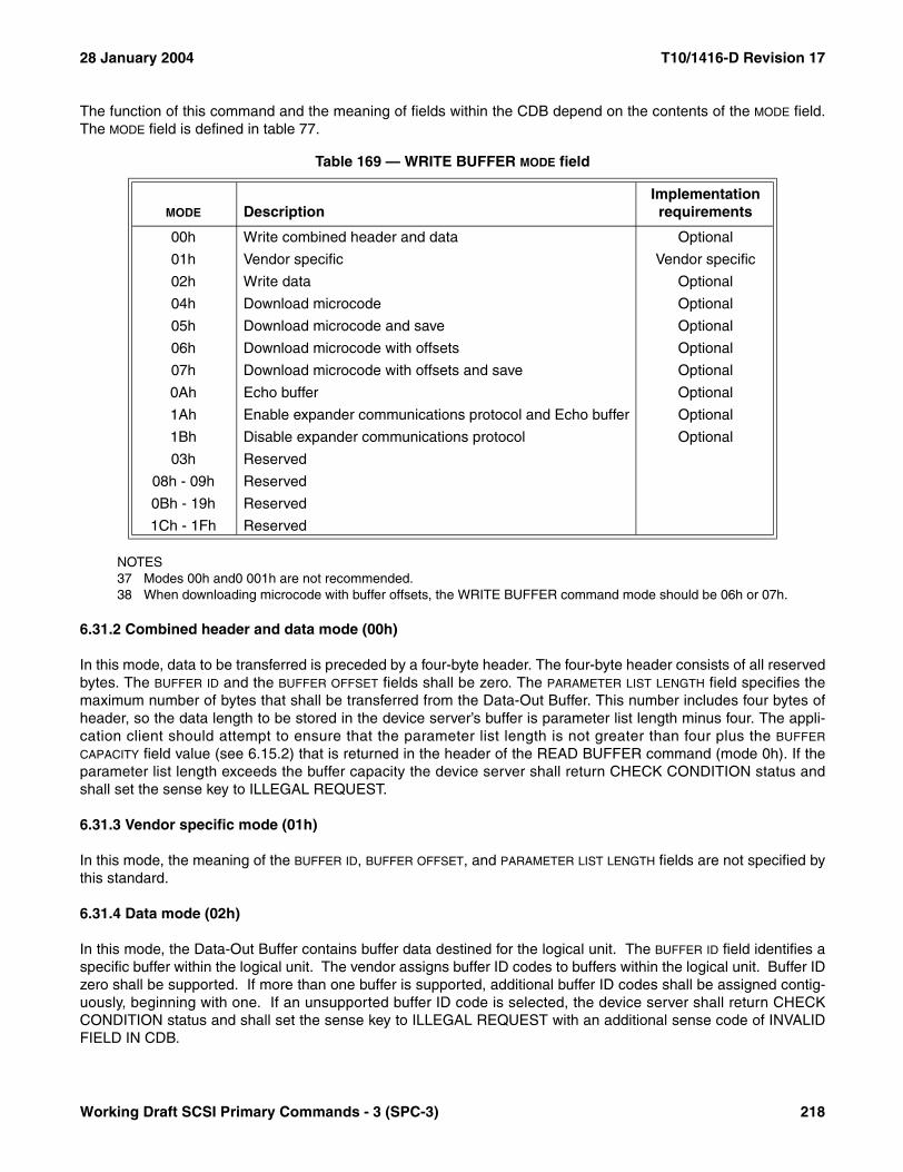
28 January 2004 T10/1416-D Revision 17
The function of this command and the meaning of fields within the CDB depend on the contents of the MODE field.The MODE field is defined in table 77.
NOTES37 Modes 00h and0 001h are not recommended.38 When downloading microcode with buffer offsets, the WRITE BUFFER command mode should be 06h or 07h.
6.31.2 Combined header and data mode (00h)
In this mode, data to be transferred is preceded by a four-byte header. The four-byte header consists of all reservedbytes. The BUFFER ID and the BUFFER OFFSET fields shall be zero. The PARAMETER LIST LENGTH field specifies themaximum number of bytes that shall be transferred from the Data-Out Buffer. This number includes four bytes ofheader, so the data length to be stored in the device server’s buffer is parameter list length minus four. The appli-cation client should attempt to ensure that the parameter list length is not greater than four plus the BUFFER
CAPACITY field value (see 6.15.2) that is returned in the header of the READ BUFFER command (mode 0h). If theparameter list length exceeds the buffer capacity the device server shall return CHECK CONDITION status andshall set the sense key to ILLEGAL REQUEST.
6.31.3 Vendor specific mode (01h)
In this mode, the meaning of the BUFFER ID, BUFFER OFFSET, and PARAMETER LIST LENGTH fields are not specified bythis standard.
6.31.4 Data mode (02h)
In this mode, the Data-Out Buffer contains buffer data destined for the logical unit. The BUFFER ID field identifies aspecific buffer within the logical unit. The vendor assigns buffer ID codes to buffers within the logical unit. Buffer IDzero shall be supported. If more than one buffer is supported, additional buffer ID codes shall be assigned contig-uously, beginning with one. If an unsupported buffer ID code is selected, the device server shall return CHECKCONDITION status and shall set the sense key to ILLEGAL REQUEST with an additional sense code of INVALIDFIELD IN CDB.
Table 169 — WRITE BUFFER MODE field
MODE DescriptionImplementation requirements
00h Write combined header and data Optional
01h Vendor specific Vendor specific
02h Write data Optional
04h Download microcode Optional
05h Download microcode and save Optional
06h Download microcode with offsets Optional
07h Download microcode with offsets and save Optional
0Ah Echo buffer Optional
1Ah Enable expander communications protocol and Echo buffer Optional
1Bh Disable expander communications protocol Optional
03h Reserved
08h - 09h Reserved
0Bh - 19h Reserved
1Ch - 1Fh Reserved
Working Draft SCSI Primary Commands - 3 (SPC-3) 218

T10/1416-D Revision 17 28 January 2004
Data are written to the logical unit buffer starting at the location specified by the BUFFER OFFSET field. The appli-cation client should conform to the offset boundary requirements returned in the READ BUFFER descriptor. If thedevice server is unable to accept the specified buffer offset, it shall return CHECK CONDITION status and it shallset the sense key to ILLEGAL REQUEST with an additional sense code of INVALID FIELD IN CDB.
The PARAMETER LIST LENGTH field specifies the maximum number of bytes that shall be transferred from theData-Out Buffer to be stored in the specified buffer beginning at the buffer offset. The application client shouldattempt to ensure that the parameter list length plus the buffer offset does not exceed the capacity of the specifiedbuffer. The capacity of the buffer may be determined by the BUFFER CAPACITY field in the READ BUFFERdescriptor. If the BUFFER OFFSET and PARAMETER LIST LENGTH fields specify a transfer in excess of the buffercapacity, the device server shall return CHECK CONDITION status and shall set the sense key to ILLEGALREQUEST with an additional sense code of INVALID FIELD IN CDB.
6.31.5 Download microcode mode (04h)
If the logical unit is unable to accept this command because of some device condition, the device server shallterminate each WRITE BUFFER command with this mode (04h) with a CHECK CONDITION status, a sense key ofILLEGAL REQUEST, and shall set the additional sense code to COMMAND SEQUENCE ERROR.
In this mode, vendor specific microcode or control information shall be transferred to the control memory space ofthe logical unit. After a hard reset, the device operation shall revert to a vendor specific condition. The meanings ofthe BUFFER ID, BUFFER OFFSET, and PARAMETER LIST LENGTH fields are not specified by this standard and are notrequired to be zero-filled. When the microcode download has completed successfully the device server shallgenerate a unit attention condition for all initiators except the one that issued the WRITE BUFFER command (seeSAM-2). The additional sense code shall be set to MICROCODE HAS BEEN CHANGED.
6.31.6 Download microcode and save mode (05h)
If the logical unit is unable to accept this command because of some device condition, the device server shallterminate each WRITE BUFFER command with this mode (05h) with a CHECK CONDITION status, a sense key ofILLEGAL REQUEST, and shall set the additional sense code to COMMAND SEQUENCE ERROR.
In this mode, vendor specific microcode or control information shall be transferred to the logical unit and, if theWRITE BUFFER command is completed successfully, also shall be saved in a nonvolatile memory space(semiconductor, disk, or other). The downloaded code shall then be effective after each hard reset until it issupplanted in another download microcode and save operation or download microcode with offsets and saveoperation. The meanings of the BUFFER ID, BUFFER OFFSET, and PARAMETER LIST LENGTH fields are not specified bythis standard and are not required to be zero-filled. When the download microcode and save command hascompleted successfully the device server shall generate a unit attention condition (see SAM-2) for all initiatorsexcept the one that issued the WRITE BUFFER command. When reporting the unit attention condition, the deviceserver shall set the additional sense code to MICROCODE HAS BEEN CHANGED.
6.31.7 Download microcode with offsets (06h)
In this mode, the application client may split the transfer of the vendor specific microcode or control informationover two or more WRITE BUFFER commands. If the logical unit is unable to accept this command because ofsome device condition, the device server shall terminate each WRITE BUFFER command with this mode (06h)with a CHECK CONDITION status, a sense key of ILLEGAL REQUEST, and shall set the additional sense code toCOMMAND SEQUENCE ERROR.
If the last WRITE BUFFER command of a set of one or more commands completes successfully, the microcode orcontrol information shall be transferred to the control memory space of the logical unit. After a hard reset, thedevice shall revert to a vendor specific condition. In this mode, the Data-Out Buffer contains vendor specific,self-describing microcode or control information.
219 Working Draft SCSI Primary Commands - 3 (SPC-3)
28 January 2004 T10/1416-D Revision 17
Since the downloaded microcode or control information may be sent using several commands, when the logicalunit detects the last download microcode with offsets and save mode WRITE BUFFER command has beenreceived, the device server shall perform any logical unit required verification of the complete set of downloadedmicrocode or control information prior to returning GOOD status for the last command. After the last commandcompletes successfully the device server shall generate a unit attention condition (see SAM-2) for all initiatorsexcept the one that issued the set of WRITE BUFFER commands. When reporting the unit attention condition, thedevice server shall set the additional sense code to MICROCODE HAS BEEN CHANGED.
If the complete set of WRITE BUFFER commands required to effect a microcode or control information change(one or more commands) are not received before a logical unit reset or I_T nexus loss occurs, the change shall notbe effective and the new microcode or control information shall be discarded.
The BUFFER ID field identifies a specific buffer within the logical unit. The vendor assigns buffer ID codes to bufferswithin the logical unit. A buffer ID value of zero shall be supported. If more than one buffer is supported, additionalbuffer ID codes shall be assigned contiguously, beginning with one. If an unsupported buffer ID code is identified,the device server shall return CHECK CONDITION status and shall set the sense key to ILLEGAL REQUEST withan additional sense code of INVALID FIELD IN CDB.
The microcode or control information are written to the logical unit buffer starting at the location specified by theBUFFER OFFSET field. The application client shall send commands that conform to the offset boundary requirements(see 6.15.5). If the device server is unable to accept the specified buffer offset, it shall return CHECK CONDITIONstatus and it shall set the sense key to ILLEGAL REQUEST with an additional sense code of INVALID FIELD INCDB.
The PARAMETER LIST LENGTH field specifies the maximum number of bytes that shall be present in the Data-OutBuffer to be stored in the specified buffer beginning at the buffer offset. The application client should attempt toensure that the parameter list length plus the buffer offset does not exceed the capacity of the specified buffer. Thecapacity of the buffer may be determined by the BUFFER CAPACITY field in the READ BUFFER descriptor. If theBUFFER OFFSET and PARAMETER LIST LENGTH fields specify a transfer in excess of the buffer capacity, the deviceserver shall return CHECK CONDITION status and shall set the sense key to ILLEGAL REQUEST with anadditional sense code of INVALID FIELD IN CDB.
6.31.8 Download microcode with offsets and save mode (07h)
In this mode, the initiator may split the transfer of the vendor specific microcode or control information over two ormore WRITE BUFFER commands. If the logical unit is unable to accept this command because of some devicecondition, the device server shall terminate each mode 07h WRITE BUFFER command with a CHECKCONDITION status, a sense key of ILLEGAL REQUEST, and shall set the additional sense code to COMMANDSEQUENCE ERROR.
If the last WRITE BUFFER command of a set of one or more commands completes successfully, the microcode orcontrol information shall be saved in a nonvolatile memory space (e.g., semiconductor, disk, or other). The saveddownloaded microcode or control information shall then be effective after each hard reset until it is supplanted byanother download microcode with save operation or download microcode with offsets and save operation. In thismode, the Data-Out Buffer contains vendor specific, self-describing microcode or control information.
Since the downloaded microcode or control information may be sent using several commands, when the logicalunit detects the last download microcode with offsets and save mode WRITE BUFFER command has beenreceived, the device server shall perform any logical unit required verification of the complete set of downloadedmicrocode or control information prior to returning GOOD status for the last command. After the last commandcompletes successfully the device server shall generate a unit attention condition (see SAM-2) for all initiatorsexcept the one that issued the set of WRITE BUFFER commands. When reporting the unit attention condition, thedevice server shall set the additional sense code to MICROCODE HAS BEEN CHANGED.
Working Draft SCSI Primary Commands - 3 (SPC-3) 220

T10/1416-D Revision 17 28 January 2004
If the complete set of WRITE BUFFER commands required to effect a microcode or control information change(one or more commands) are not received before a logical unit reset or I_T nexus loss occurs, the change shall notbe effective and the new microcode or control information shall be discarded.
The BUFFER ID field identifies a specific buffer within the logical unit. The vendor assigns buffer ID codes to bufferswithin the logical unit. A buffer ID value of zero shall be supported. If more than one buffer is supported, additionalbuffer ID codes shall be assigned contiguously, beginning with one. If an unsupported buffer ID code is identified,the device server shall return CHECK CONDITION status and shall set the sense key to ILLEGAL REQUEST withan additional sense code of INVALID FIELD IN CDB.
The microcode or control information are written to the logical unit buffer starting at the location specified by theBUFFER OFFSET field. The application client shall conform to the offset boundary requirements. If the device serveris unable to accept the specified buffer offset, it shall return CHECK CONDITION status and it shall set the sensekey to ILLEGAL REQUEST with an additional sense code of INVALID FIELD IN CDB.
The PARAMETER LIST LENGTH field specifies the maximum number of bytes that shall be present in the Data-OutBuffer to be stored in the specified buffer beginning at the buffer offset. The application client should attempt toensure that the parameter list length plus the buffer offset does not exceed the capacity of the specified buffer. Thecapacity of the buffer may be determined by the BUFFER CAPACITY field in the READ BUFFER descriptor. If theBUFFER OFFSET and PARAMETER LIST LENGTH fields specify a transfer in excess of the buffer capacity, the deviceserver shall return CHECK CONDITION status and shall set the sense key to ILLEGAL REQUEST with anadditional sense code of INVALID FIELD IN CDB.
6.31.9 Write data to echo buffer (0Ah)
In this mode the device server transfers data from the application client and stores it in an echo buffer. An echobuffer is assigned in the same manner by the target as it would for a write operation. Data shall be sent aligned onfour-byte boundaries. The BUFFER ID and BUFFER OFFSET fields are ignored in this mode.
NOTE 39 - It is recommended that the target assign echo buffers on a per initiator basis to limit the number ofexception conditions that may occur in a multi-initiator environment.
Upon successful completion of a WRITE BUFFER command the data shall be preserved in the echo buffer unlessthere is an intervening command to any logical unit in which case it may be changed.
The PARAMETER LIST LENGTH field specifies the maximum number of bytes that shall be transferred from theData-Out Buffer to be stored in the echo buffer. The application client should attempt to ensure that the parameterlist length does not exceed the capacity of the echo buffer. The capacity of the echo buffer may be determined bythe BUFFER CAPACITY field in the READ BUFFER echo buffer descriptor. If the PARAMETER LIST LENGTH fieldspecifies a transfer in excess of the buffer capacity, the device server shall return CHECK CONDITION status andshall set the sense key to ILLEGAL REQUEST with an additional sense code of INVALID FIELD IN CDB.
6.31.10 Enable expander communications protocol and Echo buffer (1Ah)
Receipt of a WRITE BUFFER command with this mode (1Ah) causes a communicative expander (see SPI-5) toenter the expanded communications protocol mode. Device servers in SCSI target devices that receive a WRITEBUFFER command with this mode shall process it as if it were a WRITE BUFFER command with mode 0Ah (see6.31.9).
6.31.11 Disable expander communications protocol (1Bh)
Receipt of a WRITE BUFFER command with this mode (1Bh) causes a communicative expander (see SPI-5) toexit the expanded communications protocol mode and return to simple expander operation. Device servers in SCSItarget devices that receive a WRITE BUFFER command with this mode shall terminate the command with aCHECK CONDITION status, the sense key shall be set to ILLEGAL REQUEST and the additional sense code shallbe set to INVALID FIELD IN CDB.
221 Working Draft SCSI Primary Commands - 3 (SPC-3)

28 January 2004 T10/1416-D Revision 17
7 Parameters for all device types
7.1 Diagnostic parameters
7.1.1 Diagnostic page format and page codes for all device types
This subclause describes the diagnostic page structure and the diagnostic pages that are applicable to all SCSIdevices. Diagnostic pages specific to each device type are described in the command standard (see 3.1.17) thatapplies to that device type.
A SEND DIAGNOSTIC command with a PF bit set to one specifies that the SEND DIAGNOSTIC parameter listconsists of zero or more diagnostic pages and that the data returned by the subsequent RECEIVE DIAGNOSTICRESULTS command shall use the diagnostic page format defined in table 170. A RECEIVE DIAGNOSTICRESULTS command with a PCV bit set to one specifies that the device server return a diagnostic page using theformat defined in table 170.
Each diagnostic page defines a function or operation that the device server shall perform as a result of a SENDDIAGNOSTIC command or the information being returned as a result of a RECEIVE DIAGNOSTIC RESULTS withthe PCV bit equal to one. The diagnostic page contains a page header followed by the data that is formattedaccording to the page code specified.
Device servers that implement diagnostic pages are only required to accept a single diagnostic page percommand.
Table 170 — Diagnostic page format
BitByte
7 6 5 4 3 2 1 0
0 PAGE CODE
1 Reserved
2 (MSB)PAGE LENGTH (n-3)
3 (LSB)
4Diagnostic parameters
n
Working Draft SCSI Primary Commands - 3 (SPC-3) 222
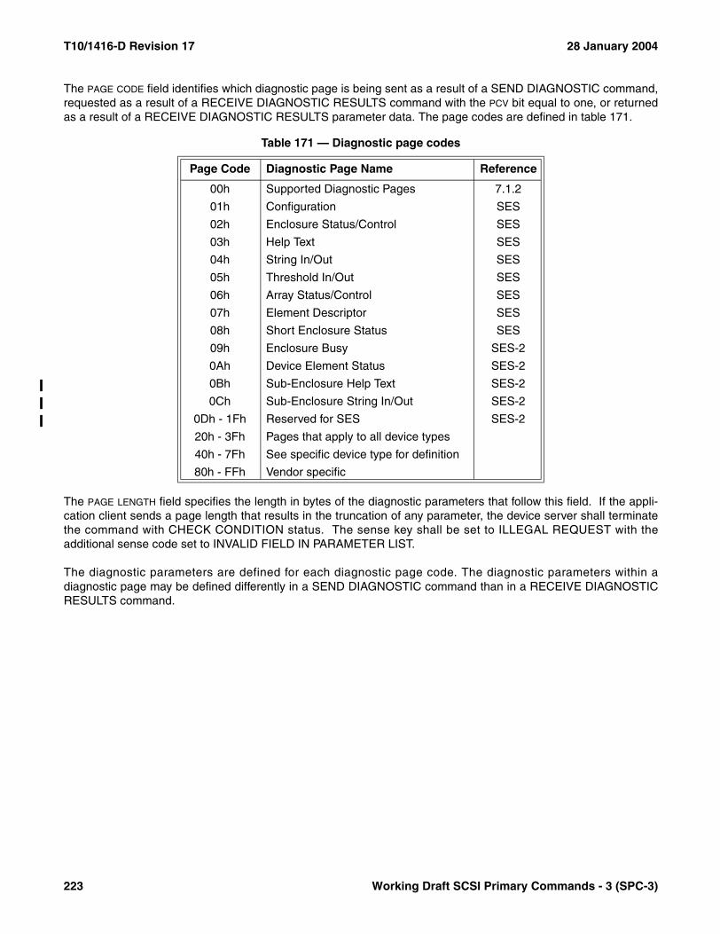
T10/1416-D Revision 17 28 January 2004
The PAGE CODE field identifies which diagnostic page is being sent as a result of a SEND DIAGNOSTIC command,requested as a result of a RECEIVE DIAGNOSTIC RESULTS command with the PCV bit equal to one, or returnedas a result of a RECEIVE DIAGNOSTIC RESULTS parameter data. The page codes are defined in table 171.
The PAGE LENGTH field specifies the length in bytes of the diagnostic parameters that follow this field. If the appli-cation client sends a page length that results in the truncation of any parameter, the device server shall terminatethe command with CHECK CONDITION status. The sense key shall be set to ILLEGAL REQUEST with theadditional sense code set to INVALID FIELD IN PARAMETER LIST.
The diagnostic parameters are defined for each diagnostic page code. The diagnostic parameters within adiagnostic page may be defined differently in a SEND DIAGNOSTIC command than in a RECEIVE DIAGNOSTICRESULTS command.
Table 171 — Diagnostic page codes
Page Code Diagnostic Page Name Reference
00h Supported Diagnostic Pages 7.1.2
01h Configuration SES
02h Enclosure Status/Control SES
03h Help Text SES
04h String In/Out SES
05h Threshold In/Out SES
06h Array Status/Control SES
07h Element Descriptor SES
08h Short Enclosure Status SES
09h Enclosure Busy SES-2
0Ah Device Element Status SES-2
0Bh Sub-Enclosure Help Text SES-2
0Ch Sub-Enclosure String In/Out SES-2
0Dh - 1Fh Reserved for SES SES-2
20h - 3Fh Pages that apply to all device types
40h - 7Fh See specific device type for definition
80h - FFh Vendor specific
223 Working Draft SCSI Primary Commands - 3 (SPC-3)

28 January 2004 T10/1416-D Revision 17
7.1.2 Supported diagnostic pages
The Supported Diagnostic Pages diagnostic page (see table 172) returns the list of diagnostic pages implementedby the device server. This diagnostic page shall be implemented if the device server implements the diagnosticpage format option of the SEND DIAGNOSTIC and RECEIVE DIAGNOSTIC RESULTS commands.
The definition of this diagnostic page for the SEND DIAGNOSTIC command includes only the first four bytes. If thePAGE LENGTH field is not zero, the device server shall terminate the SEND DIAGNOSTIC command with CHECKCONDITION status. The sense key shall be set to ILLEGAL REQUEST with an additional sense code of INVALIDFIELD IN PARAMETER LIST. This diagnostic page instructs the device server to make available the list of allsupported diagnostic pages to be returned by a subsequent RECEIVE DIAGNOSTIC RESULTS command.
The definition of this diagnostic page for the RECEIVE DIAGNOSTIC RESULTS command includes the list ofdiagnostic pages supported by the device server.
The PAGE LENGTH field specifies the length in bytes of the following supported page list.
The SUPPORTED PAGE LIST field shall contain a list of all diagnostic page codes implemented by the device server inascending order beginning with page code 00h.
Table 172 — Supported diagnostic pages
BitByte
7 6 5 4 3 2 1 0
0 PAGE CODE (00h)
1 Reserved
2 (MSB)PAGE LENGTH (n-3)
3 (LSB)
4SUPPORTED PAGE LIST
n
Working Draft SCSI Primary Commands - 3 (SPC-3) 224

T10/1416-D Revision 17 28 January 2004
7.2 Log parameters
7.2.1 Log page structure and page codes for all device types
This subclause describes the log page structure and the log pages that are applicable to all SCSI devices. Logpages specific to each device type are described in the command standard (see 3.1.17) that applies to that devicetype. The LOG SELECT command (see 6.5) supports the ability to send zero or more log pages. The LOG SENSEcommand (see 6.6) returns a single log page specified in the PAGE CODE field of the CDB.
Each log page begins with a four-byte page header followed by zero or more variable-length log parametersdefined for that log page. The log page format is defined in table 173.
The PAGE CODE field identifies which log page is being transferred.
The PAGE LENGTH field specifies the length in bytes of the following log parameters. If the application client sends alog page length that results in the truncation of any parameter, the device server shall terminate the command withCHECK CONDITION status. The sense key shall be set to ILLEGAL REQUEST with the additional sense code setto INVALID FIELD IN PARAMETER LIST.
Table 173 — Log page format
BitByte
7 6 5 4 3 2 1 0
0 PAGE CODE
1 Reserved
2 (MSB)PAGE LENGTH (n-3)
3 (LSB)
Log parameter(s)
4 Log parameter (First)(Length x)x+3
.
.
n-y+1 Log parameter (Last)(Length y)n
225 Working Draft SCSI Primary Commands - 3 (SPC-3)

28 January 2004 T10/1416-D Revision 17
Most log pages contain one or more special data structures called log parameters (see table 174). Log parametersmay be data counters of a particular event(s), the conditions under which certain operations were performed, or listparameters that contain a character string description of a particular event.
Each log parameter begins with a four-byte parameter header followed by one or more bytes of PARAMETER VALUE
data.
The PARAMETER CODE field identifies the log parameter being transferred for that log page.
The DU, DS, TSD, ETC, TMC, LBIN, and LP fields are collectively referred to as the PARAMETER CONTROL byte. Thesefields are described below in this subclause.
For cumulative log parameter values, indicated by the PC field of the LOG SELECT and LOG SENSE commands,the disable update (DU) bit is defined as follows:
a) A zero value indicates that the device server shall update the log parameter value to reflect all events thatshould be noted by that parameter; or
b) A one value indicates that the device server shall not update the log parameter value except in response toa LOG SELECT command that specifies a new value for the parameter.
NOTE 40 - When updating cumulative log parameter values, a device server may use volatile memory to hold thesevalues until a LOG SELECT or LOG SENSE command is received with an SP bit set to one or a vendor specificevent occurs. As a result the updated cumulative log parameter values may be lost if a power cycle occurs.
The DU bit is not defined for threshold values, indicated by the PC field of the LOG SENSE command, nor for listparameters as indicated by the LP bit. The device server shall ignore the value of the DU bit in any log parametersreceived with a LOG SELECT command.
A disable save (DS) bit set to zero indicates that the SCSI target device supports saving for that log parameter. Thedevice server shall save the current cumulative or the current threshold parameter value, depending on the value inthe PC field of the CDB, in response to a LOG SELECT or LOG SENSE command with an SP bit set to one. A DS bitset to one indicates that the SCSI target device does not support saving that log parameter in response to a LOGSELECT or LOG SENSE command with an SP bit set to one.
A target save disable (TSD) bit set to zero indicates that the SCSI target device implicitly saves the log parameter atvendor specific intervals. This implicit saving operation shall be done frequently enough to insure that thecumulative parameter values retain statistical significance (i.e., across power cycles). A TSD bit set to one indicatesthat either the SCSI target device does not implicitly save the log parameter or implicit saving of the log parameterhas been disabled individually by an application client setting the TSD bit to one. An application client may disable
Table 174 — Log parameter
BitByte
7 6 5 4 3 2 1 0
0 (MSB)PARAMETER CODE
1 (LSB)
2 DU DS TSD ETC TMC LBIN LP
3 PARAMETER LENGTH (n-3)
4PARAMETER VALUE
n
Working Draft SCSI Primary Commands - 3 (SPC-3) 226
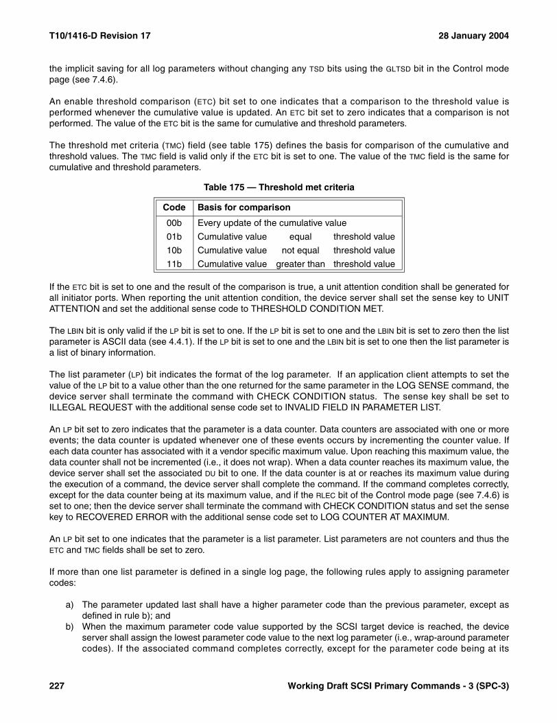
T10/1416-D Revision 17 28 January 2004
the implicit saving for all log parameters without changing any TSD bits using the GLTSD bit in the Control modepage (see 7.4.6).
An enable threshold comparison (ETC) bit set to one indicates that a comparison to the threshold value isperformed whenever the cumulative value is updated. An ETC bit set to zero indicates that a comparison is notperformed. The value of the ETC bit is the same for cumulative and threshold parameters.
The threshold met criteria (TMC) field (see table 175) defines the basis for comparison of the cumulative andthreshold values. The TMC field is valid only if the ETC bit is set to one. The value of the TMC field is the same forcumulative and threshold parameters.
If the ETC bit is set to one and the result of the comparison is true, a unit attention condition shall be generated forall initiator ports. When reporting the unit attention condition, the device server shall set the sense key to UNITATTENTION and set the additional sense code to THRESHOLD CONDITION MET.
The LBIN bit is only valid if the LP bit is set to one. If the LP bit is set to one and the LBIN bit is set to zero then the listparameter is ASCII data (see 4.4.1). If the LP bit is set to one and the LBIN bit is set to one then the list parameter isa list of binary information.
The list parameter (LP) bit indicates the format of the log parameter. If an application client attempts to set thevalue of the LP bit to a value other than the one returned for the same parameter in the LOG SENSE command, thedevice server shall terminate the command with CHECK CONDITION status. The sense key shall be set toILLEGAL REQUEST with the additional sense code set to INVALID FIELD IN PARAMETER LIST.
An LP bit set to zero indicates that the parameter is a data counter. Data counters are associated with one or moreevents; the data counter is updated whenever one of these events occurs by incrementing the counter value. Ifeach data counter has associated with it a vendor specific maximum value. Upon reaching this maximum value, thedata counter shall not be incremented (i.e., it does not wrap). When a data counter reaches its maximum value, thedevice server shall set the associated DU bit to one. If the data counter is at or reaches its maximum value duringthe execution of a command, the device server shall complete the command. If the command completes correctly,except for the data counter being at its maximum value, and if the RLEC bit of the Control mode page (see 7.4.6) isset to one; then the device server shall terminate the command with CHECK CONDITION status and set the sensekey to RECOVERED ERROR with the additional sense code set to LOG COUNTER AT MAXIMUM.
An LP bit set to one indicates that the parameter is a list parameter. List parameters are not counters and thus theETC and TMC fields shall be set to zero.
If more than one list parameter is defined in a single log page, the following rules apply to assigning parametercodes:
a) The parameter updated last shall have a higher parameter code than the previous parameter, except asdefined in rule b); and
b) When the maximum parameter code value supported by the SCSI target device is reached, the deviceserver shall assign the lowest parameter code value to the next log parameter (i.e., wrap-around parametercodes). If the associated command completes correctly, except for the parameter code being at its
Table 175 — Threshold met criteria
Code Basis for comparison
00b Every update of the cumulative value
01b Cumulative value equal threshold value
10b Cumulative value not equal threshold value
11b Cumulative value greater than threshold value
227 Working Draft SCSI Primary Commands - 3 (SPC-3)

28 January 2004 T10/1416-D Revision 17
maximum value, and if the RLEC bit of the Control mode page (see 7.4.6) is set to one; then the deviceserver shall terminate the command with CHECK CONDITION status and set the sense key toRECOVERED ERROR with the additional sense code set to LOG LIST CODES EXHAUSTED.
NOTE 41 - List parameters may be used to store the locations of defective blocks in the following manner. When adefective block is identified, a list parameter is updated to reflect the location and cause of the defect. When thenext defect is encountered, the list parameter with the next higher parameter code is updated to record this defect.The size of the log page may be made vendor specific to accommodate memory limitations. It is recommended thatone or more data counter parameters be defined for the log page to keep track of the number of valid list param-eters and the parameter code of the parameter with the oldest recorded defect. This technique may be adapted torecord other types of information.
The PARAMETER LENGTH field specifies the length in bytes of the following parameter value. If the application clientsends a parameter length value that results in the truncation of the parameter value, the device server shallterminate the command with CHECK CONDITION status. The sense key shall be set to ILLEGAL REQUEST withthe additional sense code set to INVALID FIELD IN PARAMETER LIST.
If the application client sends a log parameter value that is outside the range supported by the SCSI target device,and rounding is implemented for that parameter, the device server may either:
a) Round to an acceptable value and terminate the command as described in 5.4; orb) Terminate the command with CHECK CONDITION status and set the sense key to ILLEGAL REQUEST
with the additional sense code set to INVALID FIELD IN PARAMETER LIST.
When any counter in a log page reaches its maximum value, incrementing of all counters in that log page shallcease until reinitialized by the application client via a LOG SELECT command. If the RLEC bit of the Control modepage is one, then the device server shall report the exception condition.
Working Draft SCSI Primary Commands - 3 (SPC-3) 228
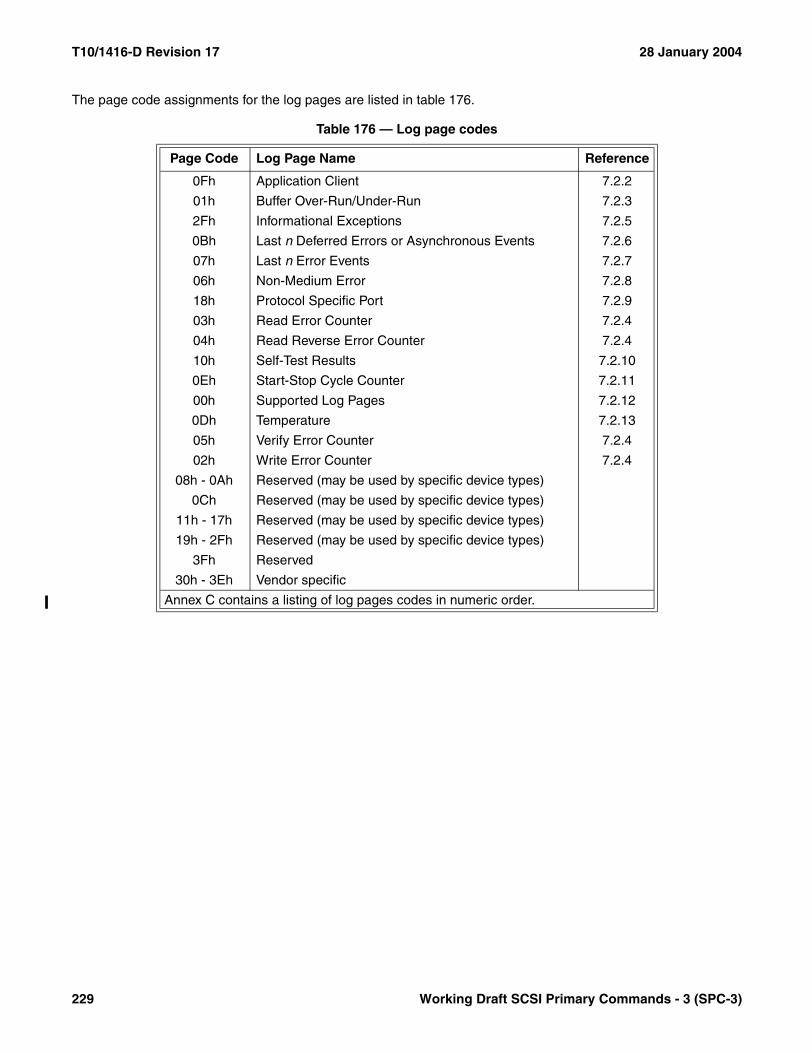
T10/1416-D Revision 17 28 January 2004
The page code assignments for the log pages are listed in table 176.
Table 176 — Log page codes
Page Code Log Page Name Reference
0Fh Application Client 7.2.2
01h Buffer Over-Run/Under-Run 7.2.3
2Fh Informational Exceptions 7.2.5
0Bh Last n Deferred Errors or Asynchronous Events 7.2.6
07h Last n Error Events 7.2.7
06h Non-Medium Error 7.2.8
18h Protocol Specific Port 7.2.9
03h Read Error Counter 7.2.4
04h Read Reverse Error Counter 7.2.4
10h Self-Test Results 7.2.10
0Eh Start-Stop Cycle Counter 7.2.11
00h Supported Log Pages 7.2.12
0Dh Temperature 7.2.13
05h Verify Error Counter 7.2.4
02h Write Error Counter 7.2.4
08h - 0Ah Reserved (may be used by specific device types)
0Ch Reserved (may be used by specific device types)
11h - 17h Reserved (may be used by specific device types)
19h - 2Fh Reserved (may be used by specific device types)
3Fh Reserved
30h - 3Eh Vendor specific
Annex C contains a listing of log pages codes in numeric order.
229 Working Draft SCSI Primary Commands - 3 (SPC-3)
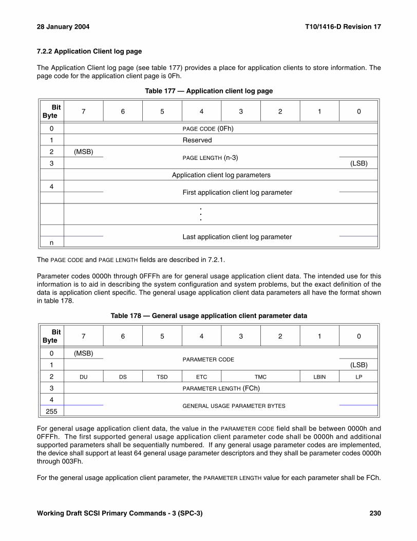
28 January 2004 T10/1416-D Revision 17
7.2.2 Application Client log page
The Application Client log page (see table 177) provides a place for application clients to store information. Thepage code for the application client page is 0Fh.
The PAGE CODE and PAGE LENGTH fields are described in 7.2.1.
Parameter codes 0000h through 0FFFh are for general usage application client data. The intended use for thisinformation is to aid in describing the system configuration and system problems, but the exact definition of thedata is application client specific. The general usage application client data parameters all have the format shownin table 178.
For general usage application client data, the value in the PARAMETER CODE field shall be between 0000h and0FFFh. The first supported general usage application client parameter code shall be 0000h and additionalsupported parameters shall be sequentially numbered. If any general usage parameter codes are implemented,the device shall support at least 64 general usage parameter descriptors and they shall be parameter codes 0000hthrough 003Fh.
For the general usage application client parameter, the PARAMETER LENGTH value for each parameter shall be FCh.
Table 177 — Application client log page
BitByte
7 6 5 4 3 2 1 0
0 PAGE CODE (0Fh)
1 Reserved
2 (MSB)PAGE LENGTH (n-3)
3 (LSB)
Application client log parameters
4First application client log parameter
.
.
.
Last application client log parametern
Table 178 — General usage application client parameter data
BitByte
7 6 5 4 3 2 1 0
0 (MSB)PARAMETER CODE
1 (LSB)
2 DU DS TSD ETC TMC LBIN LP
3 PARAMETER LENGTH (FCh)
4GENERAL USAGE PARAMETER BYTES
255
Working Draft SCSI Primary Commands - 3 (SPC-3) 230
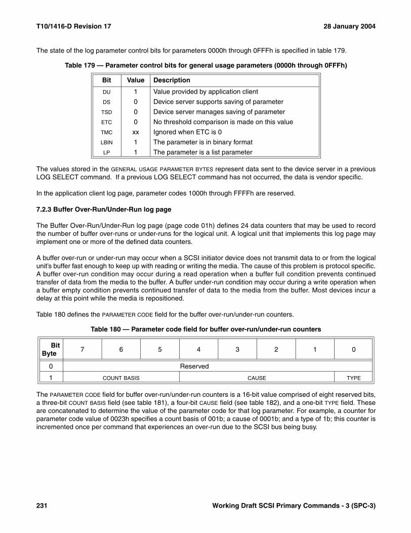
T10/1416-D Revision 17 28 January 2004
The state of the log parameter control bits for parameters 0000h through 0FFFh is specified in table 179.
The values stored in the GENERAL USAGE PARAMETER BYTES represent data sent to the device server in a previousLOG SELECT command. If a previous LOG SELECT command has not occurred, the data is vendor specific.
In the application client log page, parameter codes 1000h through FFFFh are reserved.
7.2.3 Buffer Over-Run/Under-Run log page
The Buffer Over-Run/Under-Run log page (page code 01h) defines 24 data counters that may be used to recordthe number of buffer over-runs or under-runs for the logical unit. A logical unit that implements this log page mayimplement one or more of the defined data counters.
A buffer over-run or under-run may occur when a SCSI initiator device does not transmit data to or from the logicalunit’s buffer fast enough to keep up with reading or writing the media. The cause of this problem is protocol specific.A buffer over-run condition may occur during a read operation when a buffer full condition prevents continuedtransfer of data from the media to the buffer. A buffer under-run condition may occur during a write operation whena buffer empty condition prevents continued transfer of data to the media from the buffer. Most devices incur adelay at this point while the media is repositioned.
Table 180 defines the PARAMETER CODE field for the buffer over-run/under-run counters.
The PARAMETER CODE field for buffer over-run/under-run counters is a 16-bit value comprised of eight reserved bits,a three-bit COUNT BASIS field (see table 181), a four-bit CAUSE field (see table 182), and a one-bit TYPE field. Theseare concatenated to determine the value of the parameter code for that log parameter. For example, a counter forparameter code value of 0023h specifies a count basis of 001b; a cause of 0001b; and a type of 1b; this counter isincremented once per command that experiences an over-run due to the SCSI bus being busy.
Table 179 — Parameter control bits for general usage parameters (0000h through 0FFFh)
Bit Value Description
DU 1 Value provided by application client
DS 0 Device server supports saving of parameter
TSD 0 Device server manages saving of parameter
ETC 0 No threshold comparison is made on this value
TMC xx Ignored when ETC is 0
LBIN 1 The parameter is in binary format
LP 1 The parameter is a list parameter
Table 180 — Parameter code field for buffer over-run/under-run counters
BitByte
7 6 5 4 3 2 1 0
0 Reserved
1 COUNT BASIS CAUSE TYPE
231 Working Draft SCSI Primary Commands - 3 (SPC-3)
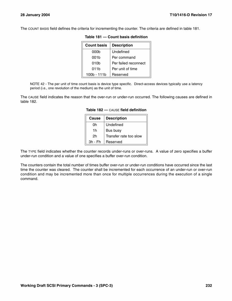
28 January 2004 T10/1416-D Revision 17
The COUNT BASIS field defines the criteria for incrementing the counter. The criteria are defined in table 181.
NOTE 42 - The per unit of time count basis is device type specific. Direct-access devices typically use a latencyperiod (i.e., one revolution of the medium) as the unit of time.
The CAUSE field indicates the reason that the over-run or under-run occurred. The following causes are defined intable 182.
The TYPE field indicates whether the counter records under-runs or over-runs. A value of zero specifies a bufferunder-run condition and a value of one specifies a buffer over-run condition.
The counters contain the total number of times buffer over-run or under-run conditions have occurred since the lasttime the counter was cleared. The counter shall be incremented for each occurrence of an under-run or over-runcondition and may be incremented more than once for multiple occurrences during the execution of a singlecommand.
Table 181 — Count basis definition
Count basis Description
000b Undefined
001b Per command
010b Per failed reconnect
011b Per unit of time
100b - 111b Reserved
Table 182 — CAUSE field definition
Cause Description
0h Undefined
1h Bus busy
2h Transfer rate too slow
3h - Fh Reserved
Working Draft SCSI Primary Commands - 3 (SPC-3) 232
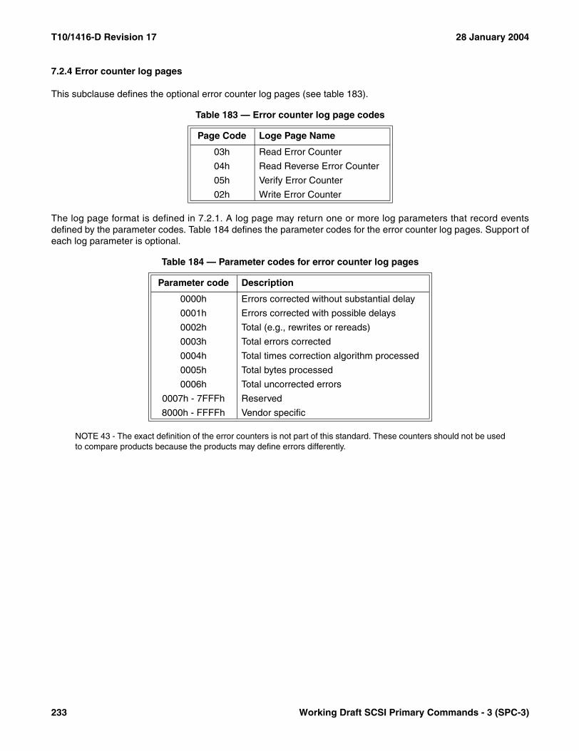
T10/1416-D Revision 17 28 January 2004
7.2.4 Error counter log pages
This subclause defines the optional error counter log pages (see table 183).
The log page format is defined in 7.2.1. A log page may return one or more log parameters that record eventsdefined by the parameter codes. Table 184 defines the parameter codes for the error counter log pages. Support ofeach log parameter is optional.
NOTE 43 - The exact definition of the error counters is not part of this standard. These counters should not be usedto compare products because the products may define errors differently.
Table 183 — Error counter log page codes
Page Code Loge Page Name
03h Read Error Counter
04h Read Reverse Error Counter
05h Verify Error Counter
02h Write Error Counter
Table 184 — Parameter codes for error counter log pages
Parameter code Description
0000h Errors corrected without substantial delay
0001h Errors corrected with possible delays
0002h Total (e.g., rewrites or rereads)
0003h Total errors corrected
0004h Total times correction algorithm processed
0005h Total bytes processed
0006h Total uncorrected errors
0007h - 7FFFh Reserved
8000h - FFFFh Vendor specific
233 Working Draft SCSI Primary Commands - 3 (SPC-3)
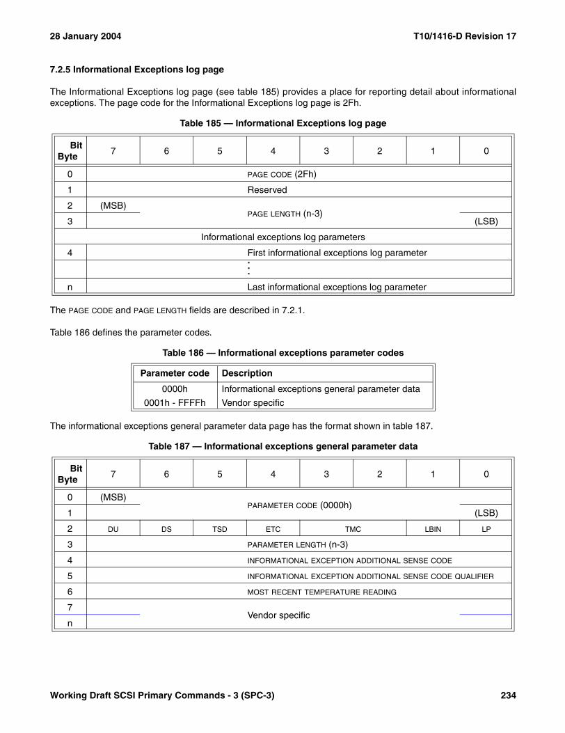
28 January 2004 T10/1416-D Revision 17
7.2.5 Informational Exceptions log page
The Informational Exceptions log page (see table 185) provides a place for reporting detail about informationalexceptions. The page code for the Informational Exceptions log page is 2Fh.
The PAGE CODE and PAGE LENGTH fields are described in 7.2.1.
Table 186 defines the parameter codes.
The informational exceptions general parameter data page has the format shown in table 187.
Table 185 — Informational Exceptions log page
BitByte
7 6 5 4 3 2 1 0
0 PAGE CODE (2Fh)
1 Reserved
2 (MSB)PAGE LENGTH (n-3)
3 (LSB)
Informational exceptions log parameters
4 First informational exceptions log parameter...
n Last informational exceptions log parameter
Table 186 — Informational exceptions parameter codes
Parameter code Description
0000h Informational exceptions general parameter data
0001h - FFFFh Vendor specific
Table 187 — Informational exceptions general parameter data
BitByte
7 6 5 4 3 2 1 0
0 (MSB)PARAMETER CODE (0000h)
1 (LSB)
2 DU DS TSD ETC TMC LBIN LP
3 PARAMETER LENGTH (n-3)
4 INFORMATIONAL EXCEPTION ADDITIONAL SENSE CODE
5 INFORMATIONAL EXCEPTION ADDITIONAL SENSE CODE QUALIFIER
6 MOST RECENT TEMPERATURE READING
7Vendor specific
n
Working Draft SCSI Primary Commands - 3 (SPC-3) 234
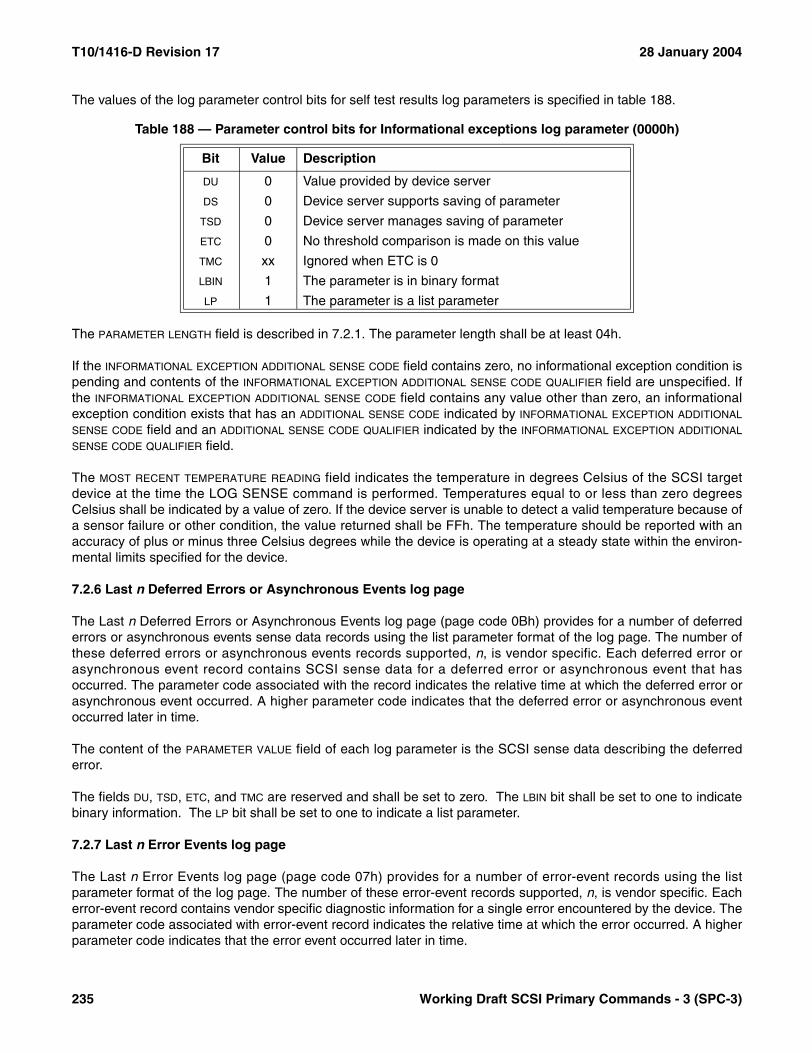
T10/1416-D Revision 17 28 January 2004
The values of the log parameter control bits for self test results log parameters is specified in table 188.
The PARAMETER LENGTH field is described in 7.2.1. The parameter length shall be at least 04h.
If the INFORMATIONAL EXCEPTION ADDITIONAL SENSE CODE field contains zero, no informational exception condition ispending and contents of the INFORMATIONAL EXCEPTION ADDITIONAL SENSE CODE QUALIFIER field are unspecified. Ifthe INFORMATIONAL EXCEPTION ADDITIONAL SENSE CODE field contains any value other than zero, an informationalexception condition exists that has an ADDITIONAL SENSE CODE indicated by INFORMATIONAL EXCEPTION ADDITIONAL
SENSE CODE field and an ADDITIONAL SENSE CODE QUALIFIER indicated by the INFORMATIONAL EXCEPTION ADDITIONAL
SENSE CODE QUALIFIER field.
The MOST RECENT TEMPERATURE READING field indicates the temperature in degrees Celsius of the SCSI targetdevice at the time the LOG SENSE command is performed. Temperatures equal to or less than zero degreesCelsius shall be indicated by a value of zero. If the device server is unable to detect a valid temperature because ofa sensor failure or other condition, the value returned shall be FFh. The temperature should be reported with anaccuracy of plus or minus three Celsius degrees while the device is operating at a steady state within the environ-mental limits specified for the device.
7.2.6 Last n Deferred Errors or Asynchronous Events log page
The Last n Deferred Errors or Asynchronous Events log page (page code 0Bh) provides for a number of deferrederrors or asynchronous events sense data records using the list parameter format of the log page. The number ofthese deferred errors or asynchronous events records supported, n, is vendor specific. Each deferred error orasynchronous event record contains SCSI sense data for a deferred error or asynchronous event that hasoccurred. The parameter code associated with the record indicates the relative time at which the deferred error orasynchronous event occurred. A higher parameter code indicates that the deferred error or asynchronous eventoccurred later in time.
The content of the PARAMETER VALUE field of each log parameter is the SCSI sense data describing the deferrederror.
The fields DU, TSD, ETC, and TMC are reserved and shall be set to zero. The LBIN bit shall be set to one to indicatebinary information. The LP bit shall be set to one to indicate a list parameter.
7.2.7 Last n Error Events log page
The Last n Error Events log page (page code 07h) provides for a number of error-event records using the listparameter format of the log page. The number of these error-event records supported, n, is vendor specific. Eacherror-event record contains vendor specific diagnostic information for a single error encountered by the device. Theparameter code associated with error-event record indicates the relative time at which the error occurred. A higherparameter code indicates that the error event occurred later in time.
Table 188 — Parameter control bits for Informational exceptions log parameter (0000h)
Bit Value Description
DU 0 Value provided by device server
DS 0 Device server supports saving of parameter
TSD 0 Device server manages saving of parameter
ETC 0 No threshold comparison is made on this value
TMC xx Ignored when ETC is 0
LBIN 1 The parameter is in binary format
LP 1 The parameter is a list parameter
235 Working Draft SCSI Primary Commands - 3 (SPC-3)
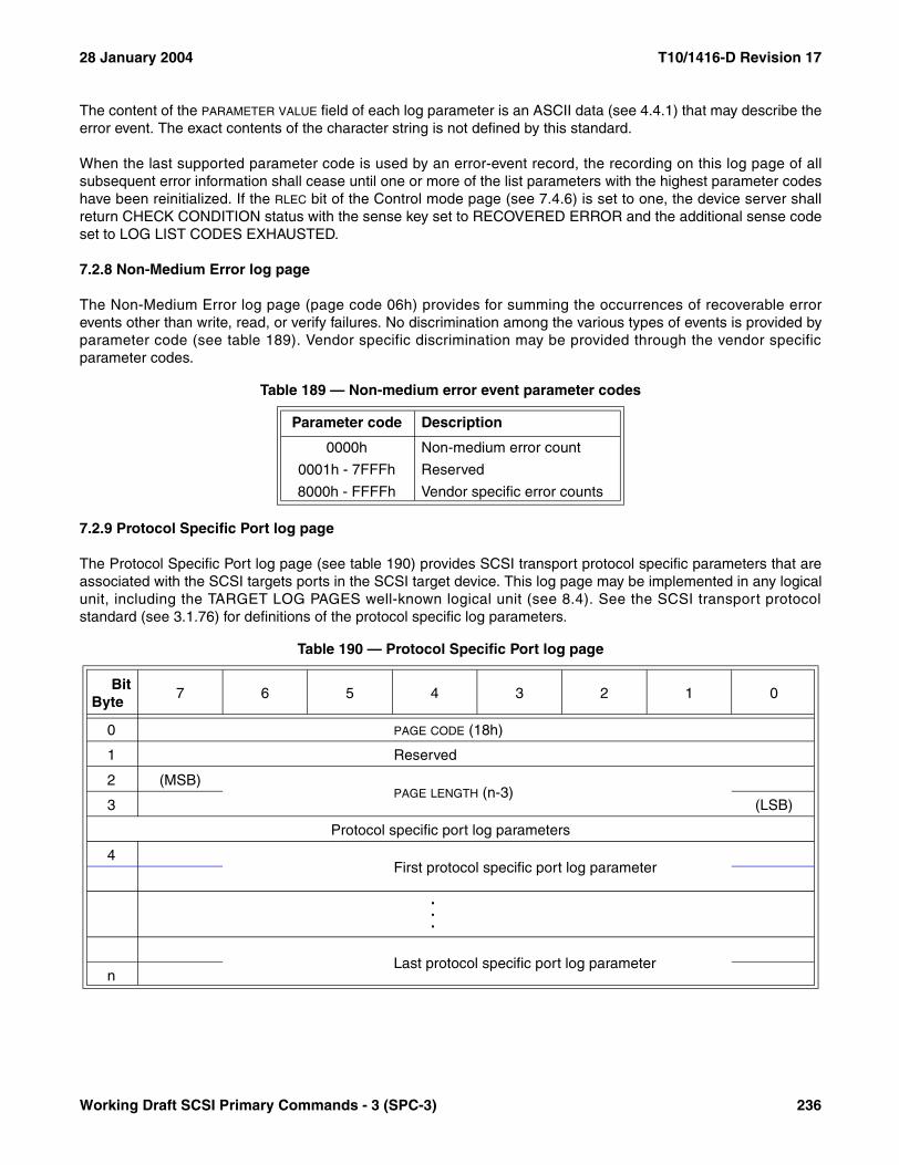
28 January 2004 T10/1416-D Revision 17
The content of the PARAMETER VALUE field of each log parameter is an ASCII data (see 4.4.1) that may describe theerror event. The exact contents of the character string is not defined by this standard.
When the last supported parameter code is used by an error-event record, the recording on this log page of allsubsequent error information shall cease until one or more of the list parameters with the highest parameter codeshave been reinitialized. If the RLEC bit of the Control mode page (see 7.4.6) is set to one, the device server shallreturn CHECK CONDITION status with the sense key set to RECOVERED ERROR and the additional sense codeset to LOG LIST CODES EXHAUSTED.
7.2.8 Non-Medium Error log page
The Non-Medium Error log page (page code 06h) provides for summing the occurrences of recoverable errorevents other than write, read, or verify failures. No discrimination among the various types of events is provided byparameter code (see table 189). Vendor specific discrimination may be provided through the vendor specificparameter codes.
7.2.9 Protocol Specific Port log page
The Protocol Specific Port log page (see table 190) provides SCSI transport protocol specific parameters that areassociated with the SCSI targets ports in the SCSI target device. This log page may be implemented in any logicalunit, including the TARGET LOG PAGES well-known logical unit (see 8.4). See the SCSI transport protocolstandard (see 3.1.76) for definitions of the protocol specific log parameters.
Table 189 — Non-medium error event parameter codes
Parameter code Description
0000h Non-medium error count
0001h - 7FFFh Reserved
8000h - FFFFh Vendor specific error counts
Table 190 — Protocol Specific Port log page
BitByte
7 6 5 4 3 2 1 0
0 PAGE CODE (18h)
1 Reserved
2 (MSB)PAGE LENGTH (n-3)
3 (LSB)
Protocol specific port log parameters
4First protocol specific port log parameter
.
.
.
Last protocol specific port log parametern
Working Draft SCSI Primary Commands - 3 (SPC-3) 236

T10/1416-D Revision 17 28 January 2004
Table 191 shows the format of a protocol specific port log parameter.
The PARAMETER CODE field contains the relative target port identifier (see 7.6.4.6) of the SCSI target port for whichthe parameter data applies. Protocol specific log parameters for relative target ports numbered greater than 65 535are not supported.
The contents of the DU, DS, TSD, ETC, LBIN, and LP bits and the TMC field are defined in 7.2.1.
The PARAMETER LENGTH field indicates the number of bytes remaining in the log parameter.
The PROTOCOL IDENTIFIER field contain one of the values shown in table 240 (see 7.5.1) to indicate the SCSItransport protocol that defines the SCSI transport protocol specific data in this log parameter. The SCSI transportprotocol specific data is defined by the corresponding SCSI transport protocol standard.
Table 191 — Protocol specific port log parameter format
BitByte
7 6 5 4 3 2 1 0
0 (MSB)PARAMETER CODE
1 (LSB)
2 DU DS TSD ETC TMC LBIN LP
3 PARAMETER LENGTH (x-3)
4 Reserved PROTOCOL IDENTIFIER
5SCSI transport protocol specific
x
237 Working Draft SCSI Primary Commands - 3 (SPC-3)

28 January 2004 T10/1416-D Revision 17
7.2.10 Self-Test Results log page
The Self-Test Results log page (see table 192) provides the results from the twenty most recent self-tests (see 5.5).Results from the most recent self-test or the self-test currently in progress shall be reported in the first self-test logparameter; results from the second most recent self-test shall be reported in the second self-test log parameter;etc. If fewer than twenty self-tests have occurred, the unused self-test log parameter entries shall be zero filled.
The PAGE CODE and PAGE LENGTH fields are described in 7.2.1.
Table 192 — Self-Test Results log page
BitByte
7 6 5 4 3 2 1 0
0 PAGE CODE (10h)
1 Reserved
2 (MSB)PAGE LENGTH (190h)
3 (LSB)
Self-test results log parameters
4First self-test results log parameter
23...
384Twentieth self-test results log parameter
403
Working Draft SCSI Primary Commands - 3 (SPC-3) 238
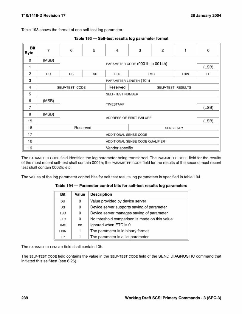
T10/1416-D Revision 17 28 January 2004
Table 193 shows the format of one self-test log parameter.
The PARAMETER CODE field identifies the log parameter being transferred. The PARAMETER CODE field for the resultsof the most recent self-test shall contain 0001h; the PARAMETER CODE field for the results of the second most recenttest shall contain 0002h; etc.
The values of the log parameter control bits for self test results log parameters is specified in table 194.
The PARAMETER LENGTH field shall contain 10h.
The SELF-TEST CODE field contains the value in the SELF-TEST CODE field of the SEND DIAGNOSTIC command thatinitiated this self-test (see 6.26).
Table 193 — Self-test results log parameter format
BitByte
7 6 5 4 3 2 1 0
0 (MSB)PARAMETER CODE (0001h to 0014h)
1 (LSB)
2 DU DS TSD ETC TMC LBIN LP
3 PARAMETER LENGTH (10h)
4 SELF-TEST CODE Reserved SELF-TEST RESULTS
5 SELF-TEST NUMBER
6 (MSB)TIMESTAMP
7 (LSB)
8 (MSB)ADDRESS OF FIRST FAILURE
15 (LSB)
16 Reserved SENSE KEY
17 ADDITIONAL SENSE CODE
18 ADDITIONAL SENSE CODE QUALIFIER
19 Vendor specific
Table 194 — Parameter control bits for self-test results log parameters
Bit Value Description
DU 0 Value provided by device server
DS 0 Device server supports saving of parameter
TSD 0 Device server manages saving of parameter
ETC 0 No threshold comparison is made on this value
TMC xx Ignored when ETC is 0
LBIN 1 The parameter is in binary format
LP 1 The parameter is a list parameter
239 Working Draft SCSI Primary Commands - 3 (SPC-3)

28 January 2004 T10/1416-D Revision 17
Table 195 defines the content of the SELF-TEST RESULTS field.
The SELF-TEST NUMBER field identifies the self-test that failed and consists of either:
a) The number of the segment that failed during the self-test; orb) The number of the test that failed and the number of the segment in which the test was run, using a vendor
specific method for placing the two values in the one field.
When the segment in which the failure occurred cannot or need not be identified, the SELF-TEST NUMBER field shallcontain 00h.
The TIMESTAMP field contains the total accumulated power-on hours for the device server at the time the self-testwas completed. If the test is still in progress, the content of the TIMESTAMP field shall be zero. If the power-onhours for the device server at the time the self-test was completed is greater than FFFFh then the content of theTIMESTAMP field shall be FFFFh.
The ADDRESS OF FIRST FAILURE field contains information that locates the failure on the media. If the logical unitimplements logical blocks, the content of the ADDRESS OF FIRST FAILURE field is the first logical block address wherea self-test error occurred. This implies nothing about the quality of any other logical block on the logical unit, sincethe testing during which the error occurred may not have been performed in a sequential manner. This value shallnot change (e.g., as the result of block reassignment). The content of the ADDRESS OF FIRST FAILURE field shall beFFFF FFFF FFFF FFFFh if no errors occurred during the self-test or if the error that occurred is not related to anidentifiable media address.
The sense key, ADDITIONAL SENSE CODE, and ADDITIONAL SENSE CODE QUALIFIER fields may contain a hierarchy ofadditional information relating to error or exception conditions that occurred during the self-test represented in thesame format used by the sense data (see 4.5).
Table 195 — Self-test results values
Value Description
0h The self-test completed without error.
1h The background self-test was aborted by the application client using a SEND DIAGNOSTIC command (see 6.26) with the SELF-TEST CODE field set to 100b (Abort background self-test).
2h The self-test routine was aborted by an application client using a method other than a SEND DIAG-NOSTIC command with the SELF-TEST CODE field set to 100b (e.g., by a task management function, or by issuing an exception command as defined in 5.5.3).
3h An unknown error occurred while the device server was executing the self-test and the device server was unable to complete the self-test.
4h The self-test completed with a failure in a test segment, and the test segment that failed is not known.
5h The first segment of the self-test failed.
6h The second segment of the self-test failed.
7h Another segment of the self-test failed (see the SELF-TEST SEGMENT NUMBER field).
8h-Eh Reserved
Fh The self-test is in progress.
Working Draft SCSI Primary Commands - 3 (SPC-3) 240
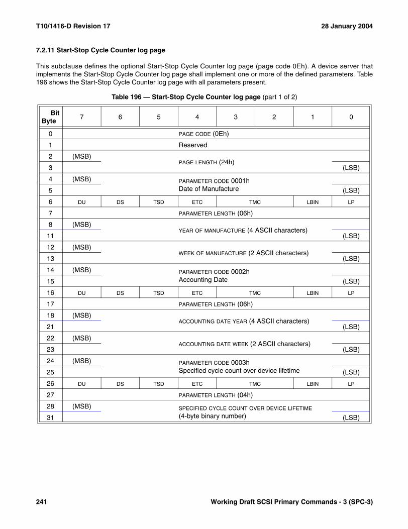
T10/1416-D Revision 17 28 January 2004
7.2.11 Start-Stop Cycle Counter log page
This subclause defines the optional Start-Stop Cycle Counter log page (page code 0Eh). A device server thatimplements the Start-Stop Cycle Counter log page shall implement one or more of the defined parameters. Table196 shows the Start-Stop Cycle Counter log page with all parameters present.
Table 196 — Start-Stop Cycle Counter log page (part 1 of 2)
BitByte
7 6 5 4 3 2 1 0
0 PAGE CODE (0Eh)
1 Reserved
2 (MSB)PAGE LENGTH (24h)
3 (LSB)
4 (MSB) PARAMETER CODE 0001hDate of Manufacture5 (LSB)
6 DU DS TSD ETC TMC LBIN LP
7 PARAMETER LENGTH (06h)
8 (MSB)YEAR OF MANUFACTURE (4 ASCII characters)
11 (LSB)
12 (MSB)WEEK OF MANUFACTURE (2 ASCII characters)
13 (LSB)
14 (MSB) PARAMETER CODE 0002hAccounting Date15 (LSB)
16 DU DS TSD ETC TMC LBIN LP
17 PARAMETER LENGTH (06h)
18 (MSB)ACCOUNTING DATE YEAR (4 ASCII characters)
21 (LSB)
22 (MSB)ACCOUNTING DATE WEEK (2 ASCII characters)
23 (LSB)
24 (MSB) PARAMETER CODE 0003hSpecified cycle count over device lifetime25 (LSB)
26 DU DS TSD ETC TMC LBIN LP
27 PARAMETER LENGTH (04h)
28 (MSB) SPECIFIED CYCLE COUNT OVER DEVICE LIFETIME
(4-byte binary number)31 (LSB)
241 Working Draft SCSI Primary Commands - 3 (SPC-3)

28 January 2004 T10/1416-D Revision 17
The year and week in the year that the device was manufactured shall be set in the parameter field defined byparameter code 0001h. The date of manufacture shall not be saveable by the application client using the LOGSELECT command (i.e., the log parameter DS bit shall be one). The date is expressed in numeric ASCII characters(30h – 39h) in the form YYYYWW, as shown in table 196. The state of the parameter control bits for parameter0001h is specified in table 197.
The accounting date specified by parameter code 0002h may be saved using a LOG SELECT command toindicate when the device was placed in service. If the parameter is not yet set or is not settable, the default valueplaced in the parameter field shall be 6 ASCII space characters (20h). The field shall not be checked for validity bythe device server. The state of the parameter control bits for parameter 0002h is specified in table 198.
The specified cycle count over device lifetime (parameter code 0003h) is a parameter provided by the deviceserver. The specified cycle count over device lifetime parameter shall not be saveable by the application clientusing the LOG SELECT command (i.e., the log parameter DS bit shall be one). The parameter value is a 4-bytebinary number. The value indicates how many stop-start cycles may typically be executed over the lifetime of the
32 (MSB) PARAMETER CODE 0004hAccumulated start-stop cycles33 (LSB)
34 DU DS TSD ETC TMC LBIN LP
35 PARAMETER LENGTH (04h)
36 (MSB) ACCUMULATED START-STOP CYCLES
(4-byte binary number)39 (LSB)
Table 197 — Parameter control bits for date of manufacture parameter (0001h)
Bit Value Description
DU 0 Value provided by device server
DS 1 Device server does not support saving of parameter
TSD 0 Device server manages saving of parameter
ETC 0 No threshold comparison is made on this value
TMC xx Ignored when ETC is 0
LBIN 0 The parameter is in ASCII format
LP 1 The parameter is a list parameter
Table 198 — Parameter control bits for accounting date parameter (0002h)
Bit Value Description
DU 0 Value provided by device server
DS 0 or 1 Device server optionally supports saving of parameter
TSD 0 Device server manages saving of parameter
ETC 0 No threshold comparison is made on this value
TMC xx Ignored when ETC is 0
LBIN 0 The parameter is in ASCII format
LP 1 The parameter is a list parameter
Table 196 — Start-Stop Cycle Counter log page (part 2 of 2)
BitByte
7 6 5 4 3 2 1 0
Working Draft SCSI Primary Commands - 3 (SPC-3) 242

T10/1416-D Revision 17 28 January 2004
device without degrading the device’s operation or reliability outside the limits specified by the manufacturer of thedevice. The state of the parameter control bits for parameter 0003h is specified in table 199.
The accumulated start-stop cycles (parameter code 0004h) is a parameter provided by the device server. Theaccumulated start-stop cycles parameter shall not be saveable by the application client using the LOG SELECTcommand (i.e., the log parameter DS bit shall be one). The parameter value is a 4-byte binary number. The valueindicates how many start-stop cycles the device has detected since its date of manufacture. The time at which thecount is incremented during a start-stop cycle is vendor specific. For rotating magnetic storage devices, a singlestart-stop cycle is defined as an operational cycle that begins with the disk spindle at rest, continues while the diskaccelerates to its normal operational rotational rate, continues during the entire period the disk is rotating,continues as the disk decelerates toward a resting state, and ends when the disk is no longer rotating. For deviceswithout a spindle or with multiple spindles, the definition of a single start-stop cycle is vendor specific. The count isincremented by one for each complete start-stop cycle. No comparison with the value of parameter 0003h shall beperformed by the device server. The state of the control bits for parameter 0004h is specified in table 199.
7.2.12 Supported Log Pages log page
The Supported Log Pages log page (see table 200) returns the list of log pages implemented by the logical unit.Logical units that implement the LOG SENSE command shall implement this log page.
This log page is not defined for the LOG SELECT command. This log page returns the list of supported log pagesfor the specified logical unit.
The PAGE LENGTH field specifies the length in bytes of the following supported log page list.
The SUPPORTED PAGE LIST field shall contain a list of all log page codes implemented by the logical unit inascending order beginning with page code 00h.
Table 199 — Parameter control bits for start-stop cycle counter parameters (0003h and 0004h)
Bit Value Description
DU 0 Value provided by device server
DS 1 Device server does not support saving of parameter
TSD 0 Device server manages saving of parameter
ETC 0 No threshold comparison is made on this value
TMC xx Ignored when ETC is 0
LBIN 1 The parameter is in binary format
LP 1 The parameter is a list parameter
Table 200 — Supported log pages
BitByte
7 6 5 4 3 2 1 0
0 PAGE CODE (00h)
1 Reserved
2 (MSB)PAGE LENGTH (n-3)
3 (LSB)
4SUPPORTED PAGE LIST
n
243 Working Draft SCSI Primary Commands - 3 (SPC-3)
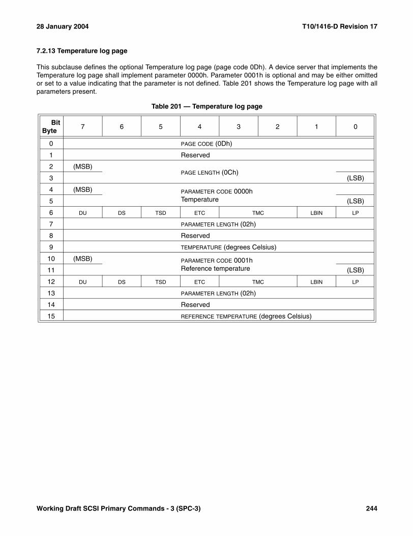
28 January 2004 T10/1416-D Revision 17
7.2.13 Temperature log page
This subclause defines the optional Temperature log page (page code 0Dh). A device server that implements theTemperature log page shall implement parameter 0000h. Parameter 0001h is optional and may be either omittedor set to a value indicating that the parameter is not defined. Table 201 shows the Temperature log page with allparameters present.
Table 201 — Temperature log page
BitByte
7 6 5 4 3 2 1 0
0 PAGE CODE (0Dh)
1 Reserved
2 (MSB)PAGE LENGTH (0Ch)
3 (LSB)
4 (MSB) PARAMETER CODE 0000hTemperature5 (LSB)
6 DU DS TSD ETC TMC LBIN LP
7 PARAMETER LENGTH (02h)
8 Reserved
9 TEMPERATURE (degrees Celsius)
10 (MSB) PARAMETER CODE 0001hReference temperature11 (LSB)
12 DU DS TSD ETC TMC LBIN LP
13 PARAMETER LENGTH (02h)
14 Reserved
15 REFERENCE TEMPERATURE (degrees Celsius)
Working Draft SCSI Primary Commands - 3 (SPC-3) 244
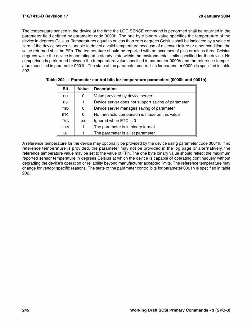
T10/1416-D Revision 17 28 January 2004
The temperature sensed in the device at the time the LOG SENSE command is performed shall be returned in theparameter field defined by parameter code 0000h. The one byte binary value specifies the temperature of thedevice in degrees Celsius. Temperatures equal to or less than zero degrees Celsius shall be indicated by a value ofzero. If the device server is unable to detect a valid temperature because of a sensor failure or other condition, thevalue returned shall be FFh. The temperature should be reported with an accuracy of plus or minus three Celsiusdegrees while the device is operating at a steady state within the environmental limits specified for the device. Nocomparison is performed between the temperature value specified in parameter 0000h and the reference temper-ature specified in parameter 0001h. The state of the parameter control bits for parameter 0000h is specified in table202.
A reference temperature for the device may optionally be provided by the device using parameter code 0001h. If noreference temperature is provided, the parameter may not be provided in the log page or alternatively, thereference temperature value may be set to the value of FFh. The one byte binary value should reflect the maximumreported sensor temperature in degrees Celsius at which the device is capable of operating continuously withoutdegrading the device's operation or reliability beyond manufacturer accepted limits. The reference temperature maychange for vendor specific reasons. The state of the parameter control bits for parameter 0001h is specified in table202.
Table 202 — Parameter control bits for temperature parameters (0000h and 0001h)
Bit Value Description
DU 0 Value provided by device server
DS 1 Device server does not support saving of parameter
TSD 0 Device server manages saving of parameter
ETC 0 No threshold comparison is made on this value
TMC xx Ignored when ETC is 0
LBIN 1 The parameter is in binary format
LP 1 The parameter is a list parameter
245 Working Draft SCSI Primary Commands - 3 (SPC-3)

28 January 2004 T10/1416-D Revision 17
7.3 Medium auxiliary memory attributes
7.3.1 Attribute format
Each medium auxiliary memory attribute shall be communicated between the application client and device serverin the format shown in table 203. This format shall be used in the parameter data for the WRITE ATTRIBUTEcommand (see 6.30) and the READ ATTRIBUTE command (see 6.14). The attribute format in this standard impliesnothing about the physical representation of an attribute in the medium auxiliary memory.
The ATTRIBUTE IDENTIFIER field contains a code value identifying the attribute (see 7.3.2).
The READ ONLY bit indicates whether the attribute is in the read only state (see 5.11). If the READ ONLY bit is set toone, the attribute is in the read only state. If the READ ONLY bit is set to zero, the attribute is in the read/write state.
The FORMAT field (see table 204) specifies the format of the data in the ATTRIBUTE VALUE field.
The ATTRIBUTE LENGTH field specifies the length in bytes of the ATTRIBUTE VALUE field.
The ATTRIBUTE VALUE field contains the current (READ ATTRIBUTE) or desired (WRITE ATTRIBUTE) value of theattribute.
Table 203 — MAM ATTRIBUTE format
BitByte
7 6 5 4 3 2 1 0
0 (MSB)ATTRIBUTE IDENTIFIER
1 (LSB)
2 READ ONLY Reserved FORMAT
3 (MSB)ATTRIBUTE LENGTH (n-4)
4 (LSB)
5ATTRIBUTE VALUE
n
Table 204 — MAM attribute formats
Format Name Description
00b BINARY The ATTRIBUTE VALUE field contains binary data.
01b ASCII The ATTRIBUTE VALUE field contains left-aligned ASCII data (see 4.4.1).
10b TEXT The attribute contains textual data. The character set is as described in the TEXT LOCALIZATION IDENTIFIER attribute (see 7.3.2.4.6).
11b Reserved
Working Draft SCSI Primary Commands - 3 (SPC-3) 246

T10/1416-D Revision 17 28 January 2004
7.3.2 Attribute identifier values
7.3.2.1 Attribute identifier values overview
The values in the ATTRIBUTE IDENTIFIER field (see 7.3.1) are assigned according to the attribute type (see 5.11) andwhether the attribute is standard or vendor unique (see table 205).
Device servers may accept and process a WRITE ATTRIBUTE command containing standardized host typeattribute identifier values (i.e., 0800h-0BFFh) or vendor unique host type attribute identifier values (i.e.,1400h-17FFh). Standardized host type attribute identifier values may be checked as described in 7.3.2.4.
Table 205 — MAM attribute identifier range assignments
Attribute Identifiers Attribute Type Standardized Subclause
0000h - 03FFh Device Yes 7.3.2.2
0400h - 07FFh Medium Yes 7.3.2.3
0800h - 0BFFh Host Yes 7.3.2.4
0C00h - 0FFFh Device Vendor Unique
1000h - 13FFh Medium Vendor Unique
1400h - 17FFh Host Vendor Unique
1800h - FFFFh Reserved
247 Working Draft SCSI Primary Commands - 3 (SPC-3)
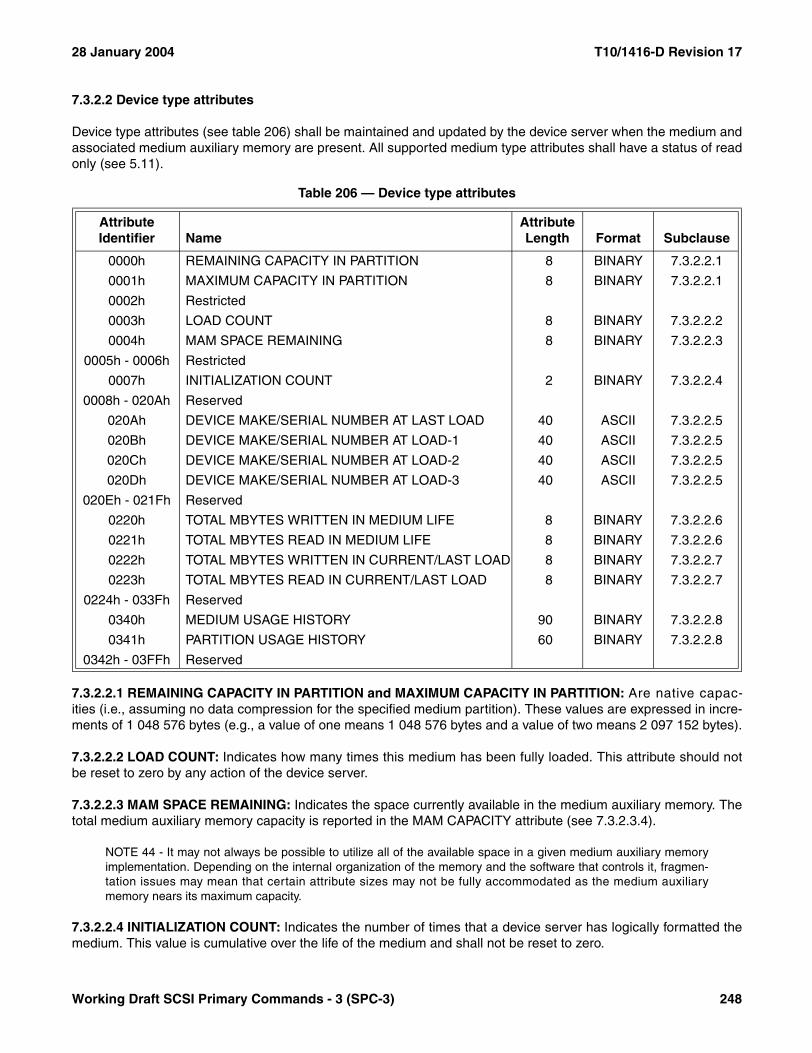
28 January 2004 T10/1416-D Revision 17
7.3.2.2 Device type attributes
Device type attributes (see table 206) shall be maintained and updated by the device server when the medium andassociated medium auxiliary memory are present. All supported medium type attributes shall have a status of readonly (see 5.11).
7.3.2.2.1 REMAINING CAPACITY IN PARTITION and MAXIMUM CAPACITY IN PARTITION: Are native capac-ities (i.e., assuming no data compression for the specified medium partition). These values are expressed in incre-ments of 1 048 576 bytes (e.g., a value of one means 1 048 576 bytes and a value of two means 2 097 152 bytes).
7.3.2.2.2 LOAD COUNT: Indicates how many times this medium has been fully loaded. This attribute should notbe reset to zero by any action of the device server.
7.3.2.2.3 MAM SPACE REMAINING: Indicates the space currently available in the medium auxiliary memory. Thetotal medium auxiliary memory capacity is reported in the MAM CAPACITY attribute (see 7.3.2.3.4).
NOTE 44 - It may not always be possible to utilize all of the available space in a given medium auxiliary memoryimplementation. Depending on the internal organization of the memory and the software that controls it, fragmen-tation issues may mean that certain attribute sizes may not be fully accommodated as the medium auxiliarymemory nears its maximum capacity.
7.3.2.2.4 INITIALIZATION COUNT: Indicates the number of times that a device server has logically formatted themedium. This value is cumulative over the life of the medium and shall not be reset to zero.
Table 206 — Device type attributes
Attribute Identifier Name
AttributeLength Format Subclause
0000h REMAINING CAPACITY IN PARTITION 8 BINARY 7.3.2.2.1
0001h MAXIMUM CAPACITY IN PARTITION 8 BINARY 7.3.2.2.1
0002h Restricted
0003h LOAD COUNT 8 BINARY 7.3.2.2.2
0004h MAM SPACE REMAINING 8 BINARY 7.3.2.2.3
0005h - 0006h Restricted
0007h INITIALIZATION COUNT 2 BINARY 7.3.2.2.4
0008h - 020Ah Reserved
020Ah DEVICE MAKE/SERIAL NUMBER AT LAST LOAD 40 ASCII 7.3.2.2.5
020Bh DEVICE MAKE/SERIAL NUMBER AT LOAD-1 40 ASCII 7.3.2.2.5
020Ch DEVICE MAKE/SERIAL NUMBER AT LOAD-2 40 ASCII 7.3.2.2.5
020Dh DEVICE MAKE/SERIAL NUMBER AT LOAD-3 40 ASCII 7.3.2.2.5
020Eh - 021Fh Reserved
0220h TOTAL MBYTES WRITTEN IN MEDIUM LIFE 8 BINARY 7.3.2.2.6
0221h TOTAL MBYTES READ IN MEDIUM LIFE 8 BINARY 7.3.2.2.6
0222h TOTAL MBYTES WRITTEN IN CURRENT/LAST LOAD 8 BINARY 7.3.2.2.7
0223h TOTAL MBYTES READ IN CURRENT/LAST LOAD 8 BINARY 7.3.2.2.7
0224h - 033Fh Reserved
0340h MEDIUM USAGE HISTORY 90 BINARY 7.3.2.2.8
0341h PARTITION USAGE HISTORY 60 BINARY 7.3.2.2.8
0342h - 03FFh Reserved
Working Draft SCSI Primary Commands - 3 (SPC-3) 248

T10/1416-D Revision 17 28 January 2004
7.3.2.2.5 DEVICE VENDOR/SERIAL NUMBER AT LAST LOAD, DEVICE VENDOR/SERIAL NUMBER AT LOAD –1, DEVICE VENDOR/SERIAL NUMBER AT LOAD –2 and DEVICE VENDOR/SERIAL NUMBER AT LOAD –3:
Give a history of the last four device servers in which the medium has been loaded. The format of the attributes isshown in table 207.
The VENDOR IDENTIFICATION field shall be the same value returned in the Standard INQUIRY data (see 6.4.2).
The PRODUCT SERIAL NUMBER field contains ASCII data (see 4.4.1) that is a vendor unique serial number. If theproduct serial number is not available, the PRODUCT SERIAL NUMBER field shall contain ASCII spaces (20h).
7.3.2.2.6 TOTAL MBYTES WRITTEN IN MEDIUM LIFE and TOTAL MBYTES READ IN MEDIUM LIFE: Indicatethe total number of data bytes that are transferred to or from the medium, after any data compression has beenapplied, over the entire medium life. These values are cumulative and shall not be reset to zero. These values areexpressed in increments of 1 048 576 bytes (e.g., a value of one means 1 048 576 bytes and a value of two means2 097 152 bytes).
7.3.2.2.7 TOTAL MBYTES WRITTEN IN CURRENT/LAST LOAD and TOTAL MBYTES READ IN CURRENT/LAST LOAD: Indicate the total number of data bytes that are transferred to or from the medium, after any datacompression has been applied, during the current load if the medium is currently loaded, or the last load if themedium is currently unloaded. The device server should reset these attributes to zero when the medium is loaded.These values are expressed in increments of 1 048 576 bytes (e.g., a value of one means 1 048 576 bytes and avalue of two means 2 097 152 bytes).
Table 207 — DEVICE VENDOR/SERIAL NUMBER attribute format
BitByte
7 6 5 4 3 2 1 0
0 (MSB)VENDOR IDENTIFICATION
7 (LSB)
8 (MSB)PRODUCT SERIAL NUMBER
39 (LSB)
249 Working Draft SCSI Primary Commands - 3 (SPC-3)

28 January 2004 T10/1416-D Revision 17
7.3.2.2.8 MEDIUM USAGE HISTORY: Provides counters (see table 208) for the entire medium. The value in eachfield is the sum for all partitions. If a field is not used it should be set to zero.
The CURRENT AMOUNT OF DATA WRITTEN field indicates the amount of data written to the medium during this load ofthe medium. This value is expressed in increments of 1 048 576 bytes (e.g., a value of one means 1 048 576 bytesand a value of two means 2 097 152 bytes).
Table 208 — MEDIUM USAGE HISTORY attribute format
BitByte
7 6 5 4 3 2 1 0
0 (MSB)CURRENT AMOUNT OF DATA WRITTEN
5 (LSB)
6 (MSB)CURRENT WRITE RETRIES COUNT
11 (LSB)
12 (MSB)CURRENT AMOUNT OF DATA READ
17 (LSB)
18 (MSB)CURRENT READ RETRIES COUNT
23 (LSB)
24 (MSB)PREVIOUS AMOUNT OF DATA WRITTEN
29 (LSB)
30 (MSB)PREVIOUS WRITE RETRIES COUNT
35 (LSB)
36 (MSB)PREVIOUS AMOUNT OF DATA READ
41 (LSB)
42 (MSB)PREVIOUS READ RETRIES COUNT
47 (LSB)
48 (MSB)TOTAL AMOUNT OF DATA WRITTEN
53 (LSB)
54 (MSB)TOTAL WRITE RETRIES COUNT
59 (LSB)
60 (MSB)TOTAL AMOUNT OF DATA READ
65 (LSB)
66 (MSB)TOTAL READ RETRIES COUNT
71 (LSB)
72 (MSB)LOAD COUNT
77 (LSB)
78 (MSB)TOTAL CHANGE PARTITION COUNT
83 (LSB)
84 (MSB)TOTAL PARTITION INITIALIZE COUNT
89 (LSB)
Working Draft SCSI Primary Commands - 3 (SPC-3) 250

T10/1416-D Revision 17 28 January 2004
The CURRENT WRITE RETRIES COUNT field indicates the total number of times a write retry occurred during this loadof the medium.1)
The CURRENT AMOUNT OF DATA READ field indicates the amount of data read from the medium during this load of themedium. This value is expressed in increments of 1 048 576 bytes (e.g., a value of one means 1 048 576 bytes anda value of two means 2 097 152 bytes).
The CURRENT READ RETRIES COUNT field indicates the number of times a read retry occurred during this load of themedium.1)
The PREVIOUS AMOUNT OF DATA WRITTEN field indicates the amount of data written to the medium during theprevious load of the medium. This value is expressed in increments of 1 048 576 bytes (e.g., a value of one means1 048 576 bytes and a value of two means 2 097 152 bytes).
The PREVIOUS WRITE RETRIES COUNT field indicates the total number of times a write retry occurred during theprevious load of the medium.1)
The PREVIOUS AMOUNT OF DATA READ field indicates the amount of data read from the medium during the previousload of the medium. This value is expressed in increments of 1 048 576 bytes (e.g., a value of one means1 048 576 bytes and a value of two means 2 097 152 bytes).
The PREVIOUS READ RETRIES COUNT field indicates the number of times a read retry occurred during the previousload of the medium.1)
The TOTAL AMOUNT OF DATA WRITTEN field indicates the amount of data written to the medium since the last mediumformat. This value is expressed in increments of 1 048 576 bytes (e.g., a value of one means 1 048 576 bytes anda value of two means 2 097 152 bytes).
The TOTAL WRITE RETRIES COUNT field indicates the total number of times a write retry occurred since the lastmedium format.1)
The TOTAL AMOUNT OF DATA READ field indicates the amount of data read from the medium since the last mediumformat. This value is expressed in increments of 1 048 576 bytes (e.g., a value of one means 1 048 576 bytes anda value of two means 2 097 152 bytes).
The TOTAL READ RETRIES COUNT field indicates the number of times a read retry occurred since the last mediumformat.1)
The LOAD COUNT field indicates the number of loads since the last medium format. This count accumulates over thelife of the medium but it is reset to zero after a medium format.
The TOTAL CHANGE PARTITION COUNT field indicates the number of times that switches between partitions have beenperformed on the medium. This count accumulates over the life of the medium but it is reset to zero after a mediumformat.
The TOTAL PARTITION INITIALIZE COUNT field indicates number of times that any of the partitions on the medium havebeen erased. This count accumulates over the life of the medium but it is reset to zero after a medium format.
1) The definition of one retry as counted by this attribute field is not part of this standard. This counter should not be used to compare products because the products may define errors differently.
251 Working Draft SCSI Primary Commands - 3 (SPC-3)
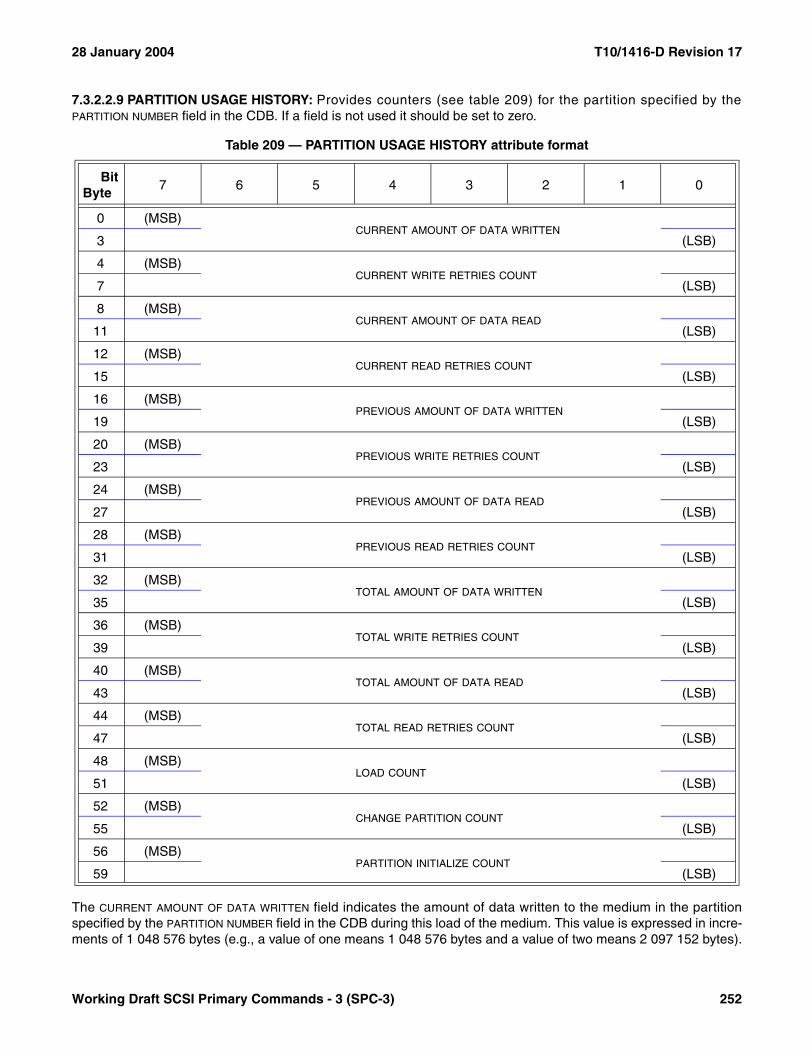
28 January 2004 T10/1416-D Revision 17
7.3.2.2.9 PARTITION USAGE HISTORY: Provides counters (see table 209) for the partition specified by thePARTITION NUMBER field in the CDB. If a field is not used it should be set to zero.
The CURRENT AMOUNT OF DATA WRITTEN field indicates the amount of data written to the medium in the partitionspecified by the PARTITION NUMBER field in the CDB during this load of the medium. This value is expressed in incre-ments of 1 048 576 bytes (e.g., a value of one means 1 048 576 bytes and a value of two means 2 097 152 bytes).
Table 209 — PARTITION USAGE HISTORY attribute format
BitByte
7 6 5 4 3 2 1 0
0 (MSB)CURRENT AMOUNT OF DATA WRITTEN
3 (LSB)
4 (MSB)CURRENT WRITE RETRIES COUNT
7 (LSB)
8 (MSB)CURRENT AMOUNT OF DATA READ
11 (LSB)
12 (MSB)CURRENT READ RETRIES COUNT
15 (LSB)
16 (MSB)PREVIOUS AMOUNT OF DATA WRITTEN
19 (LSB)
20 (MSB)PREVIOUS WRITE RETRIES COUNT
23 (LSB)
24 (MSB)PREVIOUS AMOUNT OF DATA READ
27 (LSB)
28 (MSB)PREVIOUS READ RETRIES COUNT
31 (LSB)
32 (MSB)TOTAL AMOUNT OF DATA WRITTEN
35 (LSB)
36 (MSB)TOTAL WRITE RETRIES COUNT
39 (LSB)
40 (MSB)TOTAL AMOUNT OF DATA READ
43 (LSB)
44 (MSB)TOTAL READ RETRIES COUNT
47 (LSB)
48 (MSB)LOAD COUNT
51 (LSB)
52 (MSB)CHANGE PARTITION COUNT
55 (LSB)
56 (MSB)PARTITION INITIALIZE COUNT
59 (LSB)
Working Draft SCSI Primary Commands - 3 (SPC-3) 252

T10/1416-D Revision 17 28 January 2004
The CURRENT WRITE RETRIES COUNT field indicates the total number of times a write retry occurred in the partitionspecified by the PARTITION NUMBER field in the CDB during this load of the medium.2)
The CURRENT AMOUNT OF DATA READ field indicates the amount of data read from the medium in the partitionspecified by the PARTITION NUMBER field in the CDB during this load of the medium. This value is expressed in incre-ments of 1 048 576 bytes (e.g., a value of one means 1 048 576 bytes and a value of two means 2 097 152 bytes).
The CURRENT READ RETRIES COUNT field indicates the number of times a read retry occurred in the partitionspecified by the PARTITION NUMBER field in the CDB during this load of the medium.2)
The PREVIOUS AMOUNT OF DATA WRITTEN field indicates the amount of data written to the medium in the partitionspecified by the PARTITION NUMBER field in the CDB during the previous load of the medium. This value is expressedin increments of 1 048 576 bytes (e.g., a value of one means 1 048 576 bytes and a value of two means 2 097 152bytes).
The PREVIOUS WRITE RETRIES COUNT field indicates the total number of times a write retry occurred in the partitionspecified by the PARTITION NUMBER field in the CDB during the previous load of the medium.2)
The PREVIOUS AMOUNT OF DATA READ field indicates the amount of data read from the medium in the partitionspecified by the PARTITION NUMBER field in the CDB during the previous load of the medium. This value is expressedin increments of 1 048 576 bytes (e.g., a value of one means 1 048 576 bytes and a value of two means 2 097 152bytes).
The PREVIOUS READ RETRIES COUNT field indicates the number of times a read retry occurred in the partitionspecified by the PARTITION NUMBER field in the CDB during the previous load of the medium.2)
The TOTAL AMOUNT OF DATA WRITTEN field indicates the amount of data written to the medium in the partitionspecified by the PARTITION NUMBER field in the CDB since the last medium format. This value is expressed in incre-ments of 1 048 576 bytes (e.g., a value of one means 1 048 576 bytes and a value of two means 2 097 152 bytes).
The TOTAL WRITE RETRIES COUNT field indicates the total number of times a write retry occurred in the partitionspecified by the PARTITION NUMBER field in the CDB since the last medium format.2)
The TOTAL AMOUNT OF DATA READ field indicates the amount of data read from the medium in the partition specifiedby the PARTITION NUMBER field in the CDB since the last medium format. This value is expressed in increments of1 048 576 bytes (e.g., a value of one means 1 048 576 bytes and a value of two means 2 097 152 bytes).
The TOTAL READ RETRIES COUNT field indicates the number of times a read retry occurred in the partition specifiedby the PARTITION NUMBER field in the CDB since the last medium format.2)
The LOAD COUNT field indicates the number of loads in the partition specified by the PARTITION NUMBER field in theCDB since the last medium format. This count accumulates over the life of the medium but it is reset to zero after amedium format.
The TOTAL CHANGE PARTITION COUNT field indicates the number of times that switches to the partition specified bythe PARTITION NUMBER field in the CDB have been performed on the medium. This count accumulates over the lifeof the medium but it is reset to zero after a medium format.
2) The definition of one retry as counted by this attribute field is not part of this standard. This counter should not be used to compare products because the products may define errors differently.
253 Working Draft SCSI Primary Commands - 3 (SPC-3)
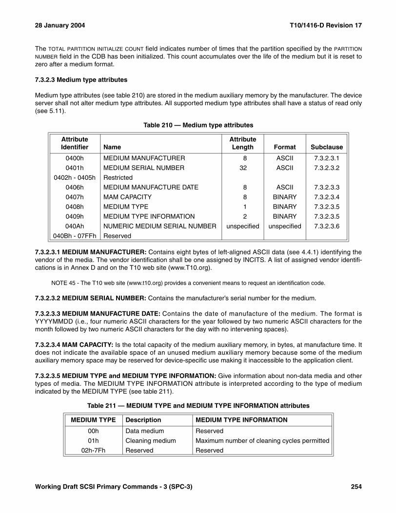
28 January 2004 T10/1416-D Revision 17
The TOTAL PARTITION INITIALIZE COUNT field indicates number of times that the partition specified by the PARTITION
NUMBER field in the CDB has been initialized. This count accumulates over the life of the medium but it is reset tozero after a medium format.
7.3.2.3 Medium type attributes
Medium type attributes (see table 210) are stored in the medium auxiliary memory by the manufacturer. The deviceserver shall not alter medium type attributes. All supported medium type attributes shall have a status of read only(see 5.11).
7.3.2.3.1 MEDIUM MANUFACTURER: Contains eight bytes of left-aligned ASCII data (see 4.4.1) identifying thevendor of the media. The vendor identification shall be one assigned by INCITS. A list of assigned vendor identifi-cations is in Annex D and on the T10 web site (www.T10.org).
NOTE 45 - The T10 web site (www.t10.org) provides a convenient means to request an identification code.
7.3.2.3.2 MEDIUM SERIAL NUMBER: Contains the manufacturer’s serial number for the medium.
7.3.2.3.3 MEDIUM MANUFACTURE DATE: Contains the date of manufacture of the medium. The format isYYYYMMDD (i.e., four numeric ASCII characters for the year followed by two numeric ASCII characters for themonth followed by two numeric ASCII characters for the day with no intervening spaces).
7.3.2.3.4 MAM CAPACITY: Is the total capacity of the medium auxiliary memory, in bytes, at manufacture time. Itdoes not indicate the available space of an unused medium auxiliary memory because some of the mediumauxiliary memory space may be reserved for device-specific use making it inaccessible to the application client.
7.3.2.3.5 MEDIUM TYPE and MEDIUM TYPE INFORMATION: Give information about non-data media and othertypes of media. The MEDIUM TYPE INFORMATION attribute is interpreted according to the type of mediumindicated by the MEDIUM TYPE (see table 211).
Table 210 — Medium type attributes
Attribute Identifier Name
AttributeLength Format Subclause
0400h MEDIUM MANUFACTURER 8 ASCII 7.3.2.3.1
0401h MEDIUM SERIAL NUMBER 32 ASCII 7.3.2.3.2
0402h - 0405h Restricted
0406h MEDIUM MANUFACTURE DATE 8 ASCII 7.3.2.3.3
0407h MAM CAPACITY 8 BINARY 7.3.2.3.4
0408h MEDIUM TYPE 1 BINARY 7.3.2.3.5
0409h MEDIUM TYPE INFORMATION 2 BINARY 7.3.2.3.5
040Ah NUMERIC MEDIUM SERIAL NUMBER unspecified unspecified 7.3.2.3.6
040Bh - 07FFh Reserved
Table 211 — MEDIUM TYPE and MEDIUM TYPE INFORMATION attributes
MEDIUM TYPE Description MEDIUM TYPE INFORMATION
00h Data medium Reserved
01h Cleaning medium Maximum number of cleaning cycles permitted
02h-7Fh Reserved Reserved
Working Draft SCSI Primary Commands - 3 (SPC-3) 254

T10/1416-D Revision 17 28 January 2004
7.3.2.3.6 NUMERIC MEDIUM SERIAL NUMBER: Contains the manufacturer’s serial number for the medium in avendor specific format.
7.3.2.4 Host type attributes
Application clients may use the WRITE ATTRIBUTE and READ ATTRIBUTE commands to maintain the attributesshown in table 212. All existent host type attributes shall have a status of read/write (see 5.11).
7.3.2.4.1 APPLICATION VENDOR: Contains eight bytes of left-aligned ASCII data (see 4.4.1) identifying themanufacturer of the application client (e.g., class driver or backup program) that last sent a WRITE ATTRIBUTEcommand to the device server while this medium auxiliary memory was accessible. The vendor identification shallbe one assigned by INCITS. A list of assigned vendor identifications is in Annex D and on the T10 web site(www.T10.org).
NOTE 46 - The T10 web site (www.t10.org) provides a convenient means to request an identification code.
7.3.2.4.2 APPLICATION NAME: Contains the name of the application client.
7.3.2.4.3 APPLICATION VERSION: Contains the version of the application client.
7.3.2.4.4 USER MEDIUM TEXT LABEL: Is the user level identifier for the medium.
7.3.2.4.5 DATE & TIME LAST WRITTEN: Contains when the application client last wrote to the medium auxiliarymemory. The format is YYYYMMDDHHMM (i.e., four numeric ASCII characters for the year followed by twonumeric ASCII characters for the month followed by two numeric ASCII characters for the day followed by twonumeric ASCII characters between 00 and 24 for the hour followed by two numeric ASCII characters for the minutewith no intervening spaces).
80h Write-once medium Reserved
81h-FFh Reserved Reserved
Table 212 — Host type attributes
Attribute Identifier Name
AttributeLength Format Subclause
0800h APPLICATION VENDOR 8 ASCII 7.3.2.4.1
0801h APPLICATION NAME 32 ASCII 7.3.2.4.2
0802h APPLICATION VERSION 8 ASCII 7.3.2.4.3
0803h USER MEDIUM TEXT LABEL 160 TEXT 7.3.2.4.4
0804h DATE AND TIME LAST WRITTEN 12 ASCII 7.3.2.4.5
0805h TEXT LOCALIZATION IDENTIFIER 1 BINARY 7.3.2.4.6
0806h BARCODE 32 ASCII 7.3.2.4.7
0807h OWNING HOST TEXTUAL NAME 80 TEXT 7.3.2.4.8
0808h MEDIA POOL 160 TEXT 7.3.2.4.9
0809h PARTITION USER TEXT LABEL 16 ASCII 7.3.2.4.10
080Ah LOAD/UNLOAD AT PARTITION 1 BINARY 7.3.2.4.11
080Bh - BFFh Reserved
Table 211 — MEDIUM TYPE and MEDIUM TYPE INFORMATION attributes
MEDIUM TYPE Description MEDIUM TYPE INFORMATION
255 Working Draft SCSI Primary Commands - 3 (SPC-3)
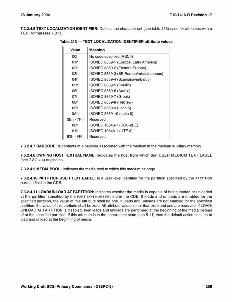
28 January 2004 T10/1416-D Revision 17
7.3.2.4.6 TEXT LOCALIZATION IDENTIFIER: Defines the character set (see table 213) used for attributes with aTEXT format (see 7.3.1).
7.3.2.4.7 BARCODE: Is contents of a barcode associated with the medium in the medium auxiliary memory.
7.3.2.4.8 OWNING HOST TEXTUAL NAME: Indicates the host from which that USER MEDIUM TEXT LABEL(see 7.3.2.4.4) originates.
7.3.2.4.9 MEDIA POOL: Indicates the media pool to which this medium belongs.
7.3.2.4.10 PARTITION USER TEXT LABEL: Is a user level identifier for the partition specified by the PARTITION
NUMBER field in the CDB.
7.3.2.4.11 LOAD/UNLOAD AT PARTITION: Indicates whether the media is capable of being loaded or unloadedat the partition specified by the PARTITION NUMBER field in the CDB. If loads and unloads are enabled for thespecified partition, the value of this attribute shall be one. If loads and unloads are not enabled for the specifiedpartition, the value of this attribute shall be zero. All attribute values other than zero and one are reserved. If LOAD/UNLOAD AT PARTITION is disabled, then loads and unloads are performed at the beginning of the media insteadof at the specified partition. If this attribute is in the nonexistent state (see 5.11) then the default action shall be toload and unload at the beginning of media.
Table 213 — TEXT LOCALIZATION IDENTIFIER attribute values
Value Meaning
00h No code specified (ASCII)
01h ISO/IEC 8859-1 (Europe, Latin America)
02h ISO/IEC 8859-2 (Eastern Europe)
03h ISO/IEC 8859-3 (SE Europe/miscellaneous)
04h ISO/IEC 8859-4 (Scandinavia/Baltic)
05h ISO/IEC 8859-5 (Cyrillic)
06h ISO/IEC 8859-6 (Arabic)
07h ISO/IEC 8859-7 (Greek)
08h ISO/IEC 8859-8 (Hebrew)
09h ISO/IEC 8859-9 (Latin 5)
0Ah ISO/IEC 8859-10 (Latin 6)
0Bh - 7Fh Reserved
80h ISO/IEC 10646-1 (UCS-2BE)
81h ISO/IEC 10646-1 (UTF-8)
82h - FFh Reserved
Working Draft SCSI Primary Commands - 3 (SPC-3) 256

T10/1416-D Revision 17 28 January 2004
7.4 Mode parameters
7.4.1 Mode parameters overview
This subclause describes the block descriptors and the mode pages and subpages used with MODE SELECT andMODE SENSE commands that are applicable to all SCSI devices. Subpages are identical to mode pages exceptthat they include a SUBPAGE CODE field that further differentiates the mode page contents. Mode pages specific toeach device type are described in the command standard (see 3.1.17) that applies to that device type.
7.4.2 Mode parameter list format
The mode parameter list shown in table 91 contains a header, followed by zero or more block descriptors, followedby zero or more variable-length mode pages. Parameter lists are defined for each device type.
7.4.3 Mode parameter header formats
The six-byte CDB mode parameter header is defined in table 215.
Table 214 — Mode parameter list
BitByte
7 6 5 4 3 2 1 0
0 - n Mode parameter header
0 - n Block descriptor(s)
0 - n Page(s)
Table 215 — Mode parameter header(6)
BitByte
7 6 5 4 3 2 1 0
0 MODE DATA LENGTH
1 MEDIUM TYPE
2 DEVICE-SPECIFIC PARAMETER
3 BLOCK DESCRIPTOR LENGTH
257 Working Draft SCSI Primary Commands - 3 (SPC-3)

28 January 2004 T10/1416-D Revision 17
The ten-byte CDB mode parameter header is defined in table 216.
When using the MODE SENSE command, the MODE DATA LENGTH field specifies the length in bytes of the followingdata that is available to be transferred. The mode data length does not include the number of bytes in the MODE
DATA LENGTH field. When using the MODE SELECT command, this field is reserved.
NOTE 47 - Targets that support more than 256 bytes of block descriptors and mode pages may need to implementten-byte mode commands. The mode data length field in the six-byte CDB header limits the returned data to 256bytes.
The contents of the MEDIUM TYPE field are unique for each device type. Refer to the mode parameters subclause ofthe specific device type command standard (see 3.1.17) for definition of these values. Some device types reservethis field.
The DEVICE-SPECIFIC PARAMETER field is unique for each device type. Refer to the mode parameters subclause ofthe specific device type command standard (see 3.1.17) for definition of this field. Some device types reserve all orpart of this field.
The Long LBA (LONGLBA) bit set to zero indicates the mode parameter block descriptors are eight bytes long andhave the format described in 7.4.4.1 or 7.4.4.2. A LONGLBA bit set to one indicates the mode parameter blockdescriptors are sixteen bytes long and have the format described in 7.4.4.3.
The BLOCK DESCRIPTOR LENGTH field specifies the length in bytes of all the block descriptors. It is equal to thenumber of block descriptors times eight if the LONGLBA bit is set to zero or times sixteen if the LONGLBA bit is set toone, and does not include mode pages or vendor specific parameters, if any, that may follow the last blockdescriptor. A block descriptor length of zero indicates that no block descriptors are included in the mode parameterlist. This condition shall not be considered an error.
Table 216 — Mode parameter header(10)
BitByte
7 6 5 4 3 2 1 0
0 (MSB)MODE DATA LENGTH
1 (LSB)
2 MEDIUM TYPE
3 DEVICE-SPECIFIC PARAMETER
4 Reserved LONGLBA
5 Reserved
6 (MSB)BLOCK DESCRIPTOR LENGTH
7 (LSB)
Working Draft SCSI Primary Commands - 3 (SPC-3) 258

T10/1416-D Revision 17 28 January 2004
7.4.4 Mode parameter block descriptor formats
7.4.4.1 General block descriptor format
When the LONGLBA bit is set to zero (see 7.4.3), the mode parameter block descriptor format for all device typesexcept direct-access is shown in table 217.
Block descriptors specify some of the medium characteristics for all or part of a logical unit. Support for blockdescriptors is optional. Each block descriptor contains a DENSITY CODE field, a NUMBER OF BLOCKS field, and aBLOCK LENGTH field. Block descriptor values are always current (i.e., saving is not supported). A unit attentioncondition (see 6.7 and SAM-2) shall be generated when any block descriptor values are changed.
The DENSITY CODE field is unique for each device type. Refer to the mode parameters subclause of the specificdevice type command standard (see 3.1.17) for definition of this field. Some device types reserve all or part of thisfield.
The NUMBER OF BLOCKS field specifies the number of logical blocks on the medium to which the DENSITY CODE andBLOCK LENGTH FIELDS apply. A value of zero indicates that all of the remaining logical blocks of the logical unit shallhave the medium characteristics specified.
If the number of logical blocks on the medium exceeds the maximum value that may be specified in the NUMBER OF
BLOCKS field a value of FF FF FFh indicates that all of the remaining logical blocks of the logical unit shall have themedium characteristics specified.
NOTES48 There may be implicit association between parameters defined in the mode pages and block descriptors. In
this case, the target may change parameters not explicitly sent with the MODE SELECT command. A subse-quent MODE SENSE command may be used to detect these changes.
49 The number of remaining logical blocks may be unknown for some device types.
The BLOCK LENGTH field specifies the length in bytes of each logical block described by the block descriptor. Forsequential-access devices, a block length of zero indicates that the logical block size written to the medium isspecified by the transfer length field in the CDB (see SSC-2).
Table 217 — General mode parameter block descriptor
BitByte
7 6 5 4 3 2 1 0
0 DENSITY CODE
1 (MSB)
NUMBER OF BLOCKS2
3 (LSB)
4 Reserved
5 (MSB)
BLOCK LENGTH6
7 (LSB)
259 Working Draft SCSI Primary Commands - 3 (SPC-3)
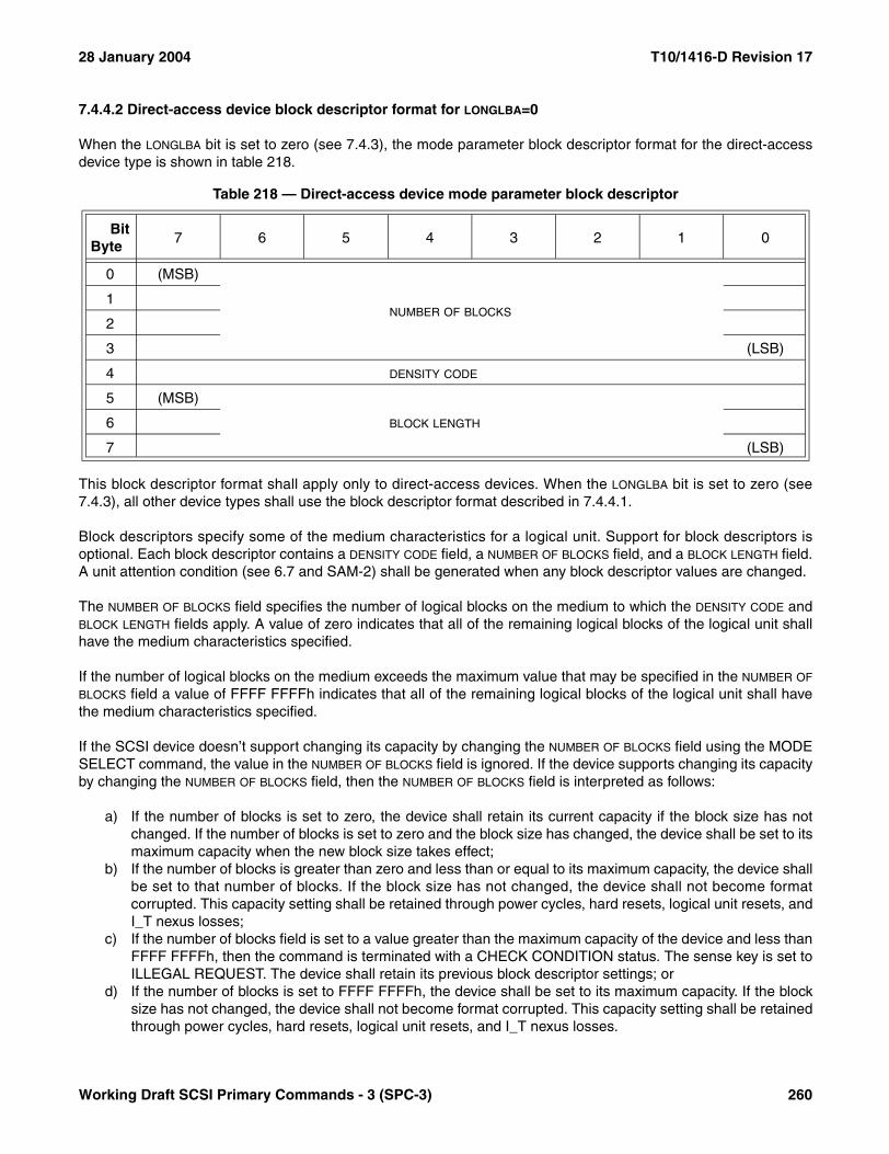
28 January 2004 T10/1416-D Revision 17
7.4.4.2 Direct-access device block descriptor format for LONGLBA=0
When the LONGLBA bit is set to zero (see 7.4.3), the mode parameter block descriptor format for the direct-accessdevice type is shown in table 218.
This block descriptor format shall apply only to direct-access devices. When the LONGLBA bit is set to zero (see7.4.3), all other device types shall use the block descriptor format described in 7.4.4.1.
Block descriptors specify some of the medium characteristics for a logical unit. Support for block descriptors isoptional. Each block descriptor contains a DENSITY CODE field, a NUMBER OF BLOCKS field, and a BLOCK LENGTH field.A unit attention condition (see 6.7 and SAM-2) shall be generated when any block descriptor values are changed.
The NUMBER OF BLOCKS field specifies the number of logical blocks on the medium to which the DENSITY CODE andBLOCK LENGTH fields apply. A value of zero indicates that all of the remaining logical blocks of the logical unit shallhave the medium characteristics specified.
If the number of logical blocks on the medium exceeds the maximum value that may be specified in the NUMBER OF
BLOCKS field a value of FFFF FFFFh indicates that all of the remaining logical blocks of the logical unit shall havethe medium characteristics specified.
If the SCSI device doesn’t support changing its capacity by changing the NUMBER OF BLOCKS field using the MODESELECT command, the value in the NUMBER OF BLOCKS field is ignored. If the device supports changing its capacityby changing the NUMBER OF BLOCKS field, then the NUMBER OF BLOCKS field is interpreted as follows:
a) If the number of blocks is set to zero, the device shall retain its current capacity if the block size has notchanged. If the number of blocks is set to zero and the block size has changed, the device shall be set to itsmaximum capacity when the new block size takes effect;
b) If the number of blocks is greater than zero and less than or equal to its maximum capacity, the device shallbe set to that number of blocks. If the block size has not changed, the device shall not become formatcorrupted. This capacity setting shall be retained through power cycles, hard resets, logical unit resets, andI_T nexus losses;
c) If the number of blocks field is set to a value greater than the maximum capacity of the device and less thanFFFF FFFFh, then the command is terminated with a CHECK CONDITION status. The sense key is set toILLEGAL REQUEST. The device shall retain its previous block descriptor settings; or
d) If the number of blocks is set to FFFF FFFFh, the device shall be set to its maximum capacity. If the blocksize has not changed, the device shall not become format corrupted. This capacity setting shall be retainedthrough power cycles, hard resets, logical unit resets, and I_T nexus losses.
Table 218 — Direct-access device mode parameter block descriptor
BitByte
7 6 5 4 3 2 1 0
0 (MSB)
NUMBER OF BLOCKS1
2
3 (LSB)
4 DENSITY CODE
5 (MSB)
BLOCK LENGTH6
7 (LSB)
Working Draft SCSI Primary Commands - 3 (SPC-3) 260

T10/1416-D Revision 17 28 January 2004
NOTE 50 - There may be implicit association between parameters defined in the mode pages and block descriptor.For direct-access devices, the block length affects the optimum values (i.e., the values that achieves the bestperformance) for the sectors per track, bytes per physical sector, track skew factor, and cylinder skew factor fields inthe format parameters mode page. In this case, the target may change parameters not explicitly sent with theMODE SELECT command. A subsequent MODE SENSE command may be used to detect these changes.
The DENSITY CODE field is unique for each device type. Refer to the mode parameters subclause of the specificdevice type command standard (see 3.1.17) for the definition of this field. Some device types reserve all or part ofthis field.
The BLOCK LENGTH field specifies the length in bytes of each logical block, excluding any protection information (seeSBC-2), described by the block descriptor.
7.4.4.3 Long LBA block descriptor format
When the LONGLBA bit is set to one (see 7.4.3), the mode parameter block descriptor format for all device types isshown in table 219.
Block descriptors specify some of the medium characteristics for all or part of a logical unit. Support for blockdescriptors is optional. Each block descriptor contains a DENSITY CODE field, a NUMBER OF BLOCKS field, and aBLOCK LENGTH field. Block descriptor values are always current (i.e., saving is not supported). A unit attentioncondition (see 6.7 and SAM-2) shall be generated when any block descriptor values are changed.
The NUMBER OF BLOCKS field specifies the number of logical blocks on the medium to which the DENSITY CODE andBLOCK LENGTH fields apply. A value of zero indicates that all of the remaining logical blocks of the logical unit shallhave the medium characteristics specified.
If the SCSI device doesn’t support changing its capacity by changing the NUMBER OF BLOCKS field using the MODESELECT command, the value in the NUMBER OF BLOCKS field is ignored. If the device supports changing itscapacity by changing the NUMBER OF BLOCKS field, then the NUMBER OF BLOCKS field is interpreted as follows:
a) If the number of blocks is set to zero, the device shall retain its current capacity if the block size has notchanged. If the number of blocks is set to zero and the block size has changed, the device shall be set toits maximum capacity when the new block size takes effect;
b) If the number of blocks is greater than zero and less than or equal to its maximum capacity, the device shallbe set to that number of blocks. If the block size has not changed, the device shall not become formatcorrupted. This capacity setting shall be retained through power cycles, hard resets, logical unit resets, andI_T nexus losses;
Table 219 — Long LBA mode parameter block descriptor
BitByte
7 6 5 4 3 2 1 0
0 (MSB)NUMBER OF BLOCKS
7 (LSB)
8 DENSITY CODE
9 Reserved
10 Reserved
11 Reserved
12 (MSB)BLOCK LENGTH
15 (LSB)
261 Working Draft SCSI Primary Commands - 3 (SPC-3)
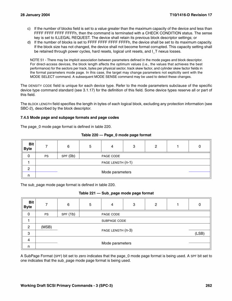
28 January 2004 T10/1416-D Revision 17
c) If the number of blocks field is set to a value greater than the maximum capacity of the device and less thanFFFF FFFF FFFF FFFFh, then the command is terminated with a CHECK CONDITION status. The sensekey is set to ILLEGAL REQUEST. The device shall retain its previous block descriptor settings; or
d) If the number of blocks is set to FFFF FFFF FFFF FFFFh, the device shall be set to its maximum capacity.If the block size has not changed, the device shall not become format corrupted. This capacity setting shallbe retained through power cycles, hard resets, logical unit resets, and I_T nexus losses.
NOTE 51 - There may be implicit association between parameters defined in the mode pages and block descriptor.For direct-access devices, the block length affects the optimum values (i.e., the values that achieves the bestperformance) for the sectors per track, bytes per physical sector, track skew factor, and cylinder skew factor fields inthe format parameters mode page. In this case, the target may change parameters not explicitly sent with theMODE SELECT command. A subsequent MODE SENSE command may be used to detect these changes.
The DENSITY CODE field is unique for each device type. Refer to the mode parameters subclause of the specificdevice type command standard (see 3.1.17) for the definition of this field. Some device types reserve all or part ofthis field.
The BLOCK LENGTH field specifies the length in bytes of each logical block, excluding any protection information (seeSBC-2), described by the block descriptor.
7.4.5 Mode page and subpage formats and page codes
The page_0 mode page format is defined in table 220.
The sub_page mode page format is defined in table 220.
A SubPage Format (SPF) bit set to zero indicates that the page_0 mode page format is being used. A SPF bit set toone indicates that the sub_page mode page format is being used.
Table 220 — Page_0 mode page format
BitByte
7 6 5 4 3 2 1 0
0 PS SPF (0b) PAGE CODE
1 PAGE LENGTH (n-1)
2Mode parameters
n
Table 221 — Sub_page mode page format
BitByte
7 6 5 4 3 2 1 0
0 PS SPF (1b) PAGE CODE
1 SUBPAGE CODE
2 (MSB)PAGE LENGTH (n-3)
3 (LSB)
4Mode parameters
n
Working Draft SCSI Primary Commands - 3 (SPC-3) 262

T10/1416-D Revision 17 28 January 2004
Each mode page contains a PAGE CODE field, a PAGE LENGTH field, and a set of mode parameters. The page codesare defined in this subclause and in the mode parameter subclauses in the command standard (see 3.1.17) for thespecific device type. Each mode page with a SPF bit equal to one contains a SUBPAGE CODE field.
When using the MODE SENSE command, a parameters saveable (PS) bit set to one indicates that the mode pagemay be saved by the target in a nonvolatile, vendor specific location. A PS bit set to zero indicates that thesupported parameters cannot be saved. When using the MODE SELECT command, the PS bit is reserved.
The PAGE CODE and SUBPAGE CODE fields identify the format and parameters defined for that mode page. Somepage codes are defined as applying to all device types and other page codes are defined for the specific devicetype. The page codes that apply to a specific device type are defined in the command standard (see 3.1.17) for thatdevice type. The applicability of each subpage code matches that of the page code with which it is associated.
When using the MODE SENSE command, if page code 00h (vendor specific mode page) is implemented, thedevice server shall return that mode page last in response to a request to return all mode pages (page code 3Fh).When using the MODE SELECT command, this mode page should be sent last.
The PAGE LENGTH field specifies the length in bytes of the mode parameters that follow. If the application client doesnot set this value to the value that is returned for the mode page by the MODE SENSE command, the device servershall terminate the command with CHECK CONDITION status. The sense key shall be set to ILLEGAL REQUESTwith the additional sense code set to INVALID FIELD IN PARAMETER LIST. The target is permitted to implement amode page that is less than the full mode page length defined in this standard, provided no field is truncated andthe PAGE LENGTH field correctly specifies the actual length implemented.
The mode parameters for each mode page are defined in the following subclauses, or in the mode parameterssubclause in the command standard (see 3.1.17) for the specific device type. Mode parameters not implementedby the target shall be set to zero.
263 Working Draft SCSI Primary Commands - 3 (SPC-3)
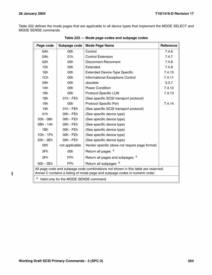
28 January 2004 T10/1416-D Revision 17
Table 222 defines the mode pages that are applicable to all device types that implement the MODE SELECT andMODE SENSE commands.
Table 222 — Mode page codes and subpage codes
Page code Subpage code Mode Page Name Reference
0Ah 00h Control 7.4.6
0Ah 01h Control Extension 7.4.7
02h 00h Disconnect-Reconnect 7.4.8
15h 00h Extended 7.4.9
16h 00h Extended Device-Type Specific 7.4.10
1Ch 00h Informational Exceptions Control 7.4.11
09h 00h obsolete 3.3.7
1Ah 00h Power Condition 7.4.12
18h 00h Protocol Specific LUN 7.4.13
18h 01h - FEh (See specific SCSI transport protocol)
19h 00h Protocol Specific Port 7.4.14
19h 01h - FEh (See specific SCSI transport protocol)
01h 00h - FEh (See specific device type)
03h - 08h 00h - FEh (See specific device type)
0Bh - 14h 00h - FEh (See specific device type)
1Bh 00h - FEh (See specific device type)
1Dh - 1Fh 00h - FEh (See specific device type)
20h - 3Eh 00h - FEh (See specific device type)
00h not applicable Vendor specific (does not require page format)
3Fh 00h Return all pages a
3Fh FFh Return all pages and subpages a
00h - 3Eh FFh Return all subpages a
All page code and subpage code combinations not shown in this table are reserved.Annex C contains a listing of mode page and subpage codes in numeric order.a Valid only for the MODE SENSE command
Working Draft SCSI Primary Commands - 3 (SPC-3) 264

T10/1416-D Revision 17 28 January 2004
7.4.6 Control mode page
The Control mode page (see table 223) provides controls over SCSI features that are applicable to all device types(e.g., task set management and error logging). If a field in this mode page is changed while there is a task alreadyin the task set, it is vendor specific whether the old or new value of the field applies to that task. The mode pagepolicy (see 6.7) for this mode page shall be shared, per initiator port, or per I_T nexus.
The PS bit, SPF bit, PAGE CODE field, and PAGE LENGTH field are described in 7.4.5.
A task set type field (TST) specifies the type of task set in the logical unit (see table 224).
If the mode page policy for this mode page is per-initiator port or per-I_T nexus, the TST field, if changeable, shallreflect in the mode pages for all initiator ports the state selected by the most recent MODE SELECT from anyinitiator port (i.e., the TST field is always shared). If the most recent MODE SELECT changes the setting of this fieldthe device server shall establish a unit attention condition for all initiator ports except the one that issued the MODESELECT command (see SAM-2). The device server shall set the additional sense code to MODE PARAMETERSCHANGED.
A descriptor format sense data (D_SENSE) bit set to zero specifies that the device server shall return the fixedformat sense data (see 4.5.3) when returning sense data in the same I_T_L_Q nexus transaction (see 3.1.39) as aCHECK CONDITION status. A D_SENSE bit set to one specifies that the device server shall return descriptor formatsense data (see 4.5.2) when returning sense data in the same I_T_L_Q nexus transaction as a CHECKCONDITION status.
Table 223 — Control mode page
BitByte
7 6 5 4 3 2 1 0
0 PS SPF (0b) PAGE CODE (0Ah)
1 PAGE LENGTH (0Ah)
2 TST Reserved D_SENSE GLTSD RLEC
3 QUEUE ALGORITHM MODIFIER Reserved QERR Obsolete
4 TAS RAC UA_INTLCK_CTRL SWP Obsolete
5 APTG_OWN Reserved AUTOLOAD MODE
6 Obsolete
7
8 (MSB)BUSY TIMEOUT PERIOD
9 (LSB)
10 (MSB)EXTENDED SELF-TEST COMPLETION TIME
11 (LSB)
Table 224 — Task set type
Value Description
000b The logical unit maintains one task set for all initiator ports
001b The logical unit maintains separate task sets for each initiator port regardless of target port
010b - 111b Reserved
265 Working Draft SCSI Primary Commands - 3 (SPC-3)
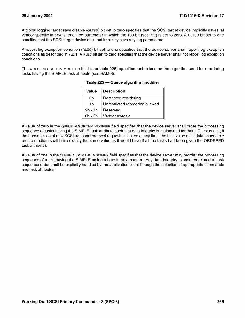
28 January 2004 T10/1416-D Revision 17
A global logging target save disable (GLTSD) bit set to zero specifies that the SCSI target device implicitly saves, atvendor specific intervals, each log parameter in which the TSD bit (see 7.2) is set to zero. A GLTSD bit set to onespecifies that the SCSI target device shall not implicitly save any log parameters.
A report log exception condition (RLEC) bit set to one specifies that the device server shall report log exceptionconditions as described in 7.2.1. A RLEC bit set to zero specifies that the device server shall not report log exceptionconditions.
The QUEUE ALGORITHM MODIFIER field (see table 225) specifies restrictions on the algorithm used for reorderingtasks having the SIMPLE task attribute (see SAM-3).
A value of zero in the QUEUE ALGORITHM MODIFIER field specifies that the device server shall order the processingsequence of tasks having the SIMPLE task attribute such that data integrity is maintained for that I_T nexus (i.e., ifthe transmission of new SCSI transport protocol requests is halted at any time, the final value of all data observableon the medium shall have exactly the same value as it would have if all the tasks had been given the ORDEREDtask attribute).
A value of one in the QUEUE ALGORITHM MODIFIER field specifies that the device server may reorder the processingsequence of tasks having the SIMPLE task attribute in any manner. Any data integrity exposures related to tasksequence order shall be explicitly handled by the application client through the selection of appropriate commandsand task attributes.
Table 225 — Queue algorithm modifier
Value Description
0h Restricted reordering
1h Unrestricted reordering allowed
2h - 7h Reserved
8h - Fh Vendor specific
Working Draft SCSI Primary Commands - 3 (SPC-3) 266

T10/1416-D Revision 17 28 January 2004
The queue error management (QERR) field (see table 226) specifies how the device server shall handle other taskswhen one task receives a CHECK CONDITION status (see SAM-3). The task set type (see the TST field definitionin this subclause) defines which other tasks are affected. If the TST field equals 000b, then all tasks from all initiatorports are affected. If the TST field equals 001b, then only tasks from the initiator port that receives the CHECKCONDITION status are affected.
A task aborted status (TAS) bit set to zero specifies that aborted tasks shall be terminated by the device serverwithout any response to the application client. A TAS bit set to one specifies that tasks aborted by the actions ofanother initiator port shall be terminated with a TASK ABORTED status (see SAM-2).
The report a check (RAC) bit provides control of reporting long busy conditions or CHECK CONDITION status. ARAC bit set to one specifies that a CHECK CONDITION status should be reported rather than a long busy condition(e.g., longer than the busy timeout period). A RAC bit set to zero specifies that long busy conditions (e.g., busycondition during auto contingent allegiance) may be reported.
Table 226 — Queue error management (QERR) field
Value Definition
00b If an ACA condition is established, the affected tasks in the task set shall resume after the ACA condition is cleared (see SAM-3). Otherwise, all tasks other than the task that received the CHECK CONDITION status shall be processed as if no error occurred.
01b All the affected tasks in the task set shall be aborted when the CHECK CONDITION status is sent. If the TAS bit is set to zero, a unit attention condition (see SAM-2) shall be generated for each initiator port that had tasks aborted except for the initiator port to which the CHECK CONDITION status was sent. The device server shall set the additional sense code to COMMANDS CLEARED BY ANOTHER INITIATOR. If the TAS bit is set to one, all affected tasks for initiator ports other than the initiator port for which the CHECK CONDITION status was sent shall be completed with a TASK ABORTED status and no unit attention shall be generated. For the initiator port to which the CHECK CONDITION status is sent, no status shall be sent for the tasks that are aborted.
10b Reserved
11b Affected tasks in the task set belonging to the initiator port to which a CHECK CONDITION status is sent shall be aborted when the status is sent.
267 Working Draft SCSI Primary Commands - 3 (SPC-3)
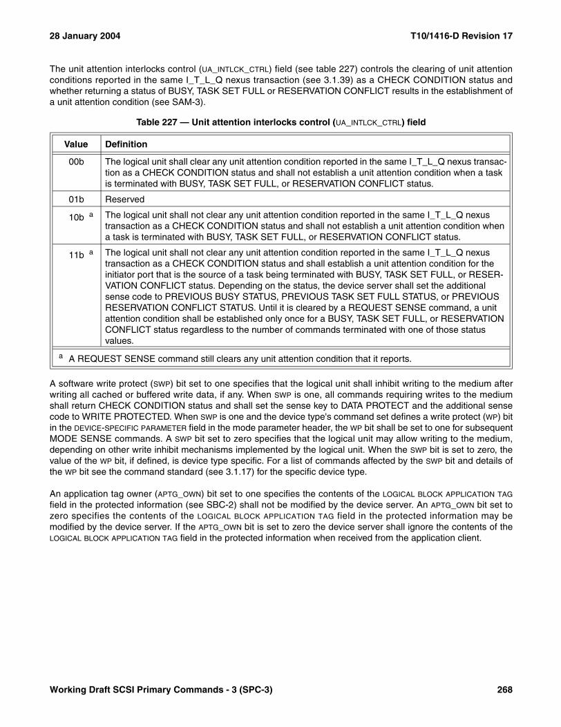
28 January 2004 T10/1416-D Revision 17
The unit attention interlocks control (UA_INTLCK_CTRL) field (see table 227) controls the clearing of unit attentionconditions reported in the same I_T_L_Q nexus transaction (see 3.1.39) as a CHECK CONDITION status andwhether returning a status of BUSY, TASK SET FULL or RESERVATION CONFLICT results in the establishment ofa unit attention condition (see SAM-3).
A software write protect (SWP) bit set to one specifies that the logical unit shall inhibit writing to the medium afterwriting all cached or buffered write data, if any. When SWP is one, all commands requiring writes to the mediumshall return CHECK CONDITION status and shall set the sense key to DATA PROTECT and the additional sensecode to WRITE PROTECTED. When SWP is one and the device type's command set defines a write protect (WP) bitin the DEVICE-SPECIFIC PARAMETER field in the mode parameter header, the WP bit shall be set to one for subsequentMODE SENSE commands. A SWP bit set to zero specifies that the logical unit may allow writing to the medium,depending on other write inhibit mechanisms implemented by the logical unit. When the SWP bit is set to zero, thevalue of the WP bit, if defined, is device type specific. For a list of commands affected by the SWP bit and details ofthe WP bit see the command standard (see 3.1.17) for the specific device type.
An application tag owner (APTG_OWN) bit set to one specifies the contents of the LOGICAL BLOCK APPLICATION TAG
field in the protected information (see SBC-2) shall not be modified by the device server. An APTG_OWN bit set tozero specifies the contents of the LOGICAL BLOCK APPLICATION TAG field in the protected information may bemodified by the device server. If the APTG_OWN bit is set to zero the device server shall ignore the contents of theLOGICAL BLOCK APPLICATION TAG field in the protected information when received from the application client.
Table 227 — Unit attention interlocks control (UA_INTLCK_CTRL) field
Value Definition
00b The logical unit shall clear any unit attention condition reported in the same I_T_L_Q nexus transac-tion as a CHECK CONDITION status and shall not establish a unit attention condition when a task is terminated with BUSY, TASK SET FULL, or RESERVATION CONFLICT status.
01b Reserved
10b a The logical unit shall not clear any unit attention condition reported in the same I_T_L_Q nexus transaction as a CHECK CONDITION status and shall not establish a unit attention condition when a task is terminated with BUSY, TASK SET FULL, or RESERVATION CONFLICT status.
11b a The logical unit shall not clear any unit attention condition reported in the same I_T_L_Q nexus transaction as a CHECK CONDITION status and shall establish a unit attention condition for the initiator port that is the source of a task being terminated with BUSY, TASK SET FULL, or RESER-VATION CONFLICT status. Depending on the status, the device server shall set the additional sense code to PREVIOUS BUSY STATUS, PREVIOUS TASK SET FULL STATUS, or PREVIOUS RESERVATION CONFLICT STATUS. Until it is cleared by a REQUEST SENSE command, a unit attention condition shall be established only once for a BUSY, TASK SET FULL, or RESERVATION CONFLICT status regardless to the number of commands terminated with one of those status values.
a A REQUEST SENSE command still clears any unit attention condition that it reports.
Working Draft SCSI Primary Commands - 3 (SPC-3) 268
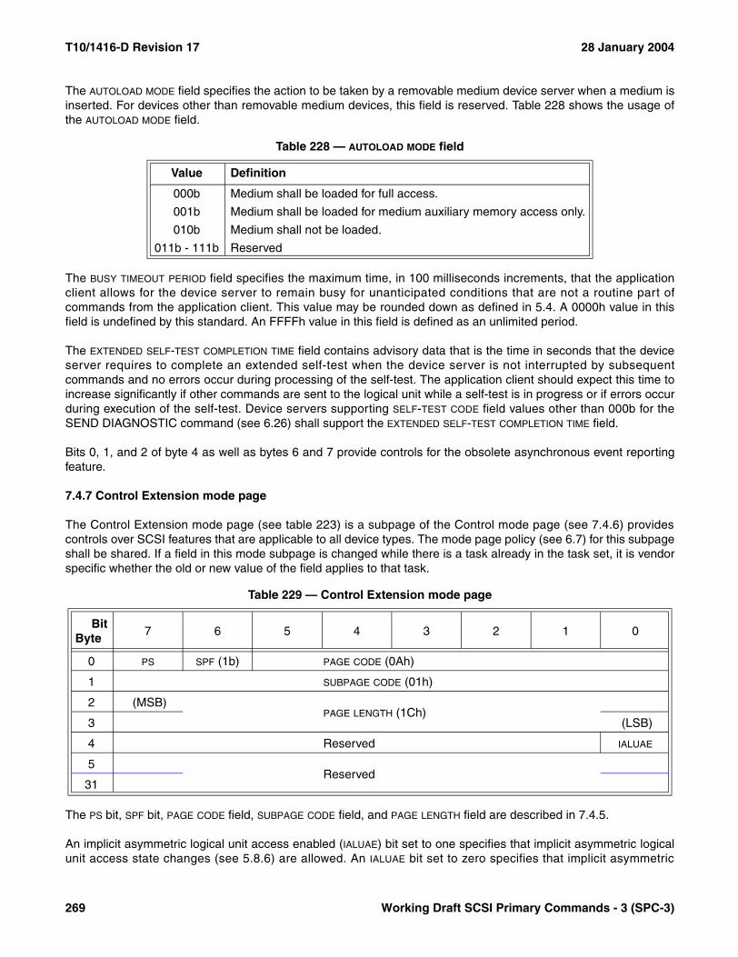
T10/1416-D Revision 17 28 January 2004
The AUTOLOAD MODE field specifies the action to be taken by a removable medium device server when a medium isinserted. For devices other than removable medium devices, this field is reserved. Table 228 shows the usage ofthe AUTOLOAD MODE field.
The BUSY TIMEOUT PERIOD field specifies the maximum time, in 100 milliseconds increments, that the applicationclient allows for the device server to remain busy for unanticipated conditions that are not a routine part ofcommands from the application client. This value may be rounded down as defined in 5.4. A 0000h value in thisfield is undefined by this standard. An FFFFh value in this field is defined as an unlimited period.
The EXTENDED SELF-TEST COMPLETION TIME field contains advisory data that is the time in seconds that the deviceserver requires to complete an extended self-test when the device server is not interrupted by subsequentcommands and no errors occur during processing of the self-test. The application client should expect this time toincrease significantly if other commands are sent to the logical unit while a self-test is in progress or if errors occurduring execution of the self-test. Device servers supporting SELF-TEST CODE field values other than 000b for theSEND DIAGNOSTIC command (see 6.26) shall support the EXTENDED SELF-TEST COMPLETION TIME field.
Bits 0, 1, and 2 of byte 4 as well as bytes 6 and 7 provide controls for the obsolete asynchronous event reportingfeature.
7.4.7 Control Extension mode page
The Control Extension mode page (see table 223) is a subpage of the Control mode page (see 7.4.6) providescontrols over SCSI features that are applicable to all device types. The mode page policy (see 6.7) for this subpageshall be shared. If a field in this mode subpage is changed while there is a task already in the task set, it is vendorspecific whether the old or new value of the field applies to that task.
The PS bit, SPF bit, PAGE CODE field, SUBPAGE CODE field, and PAGE LENGTH field are described in 7.4.5.
An implicit asymmetric logical unit access enabled (IALUAE) bit set to one specifies that implicit asymmetric logicalunit access state changes (see 5.8.6) are allowed. An IALUAE bit set to zero specifies that implicit asymmetric
Table 228 — AUTOLOAD MODE field
Value Definition
000b Medium shall be loaded for full access.
001b Medium shall be loaded for medium auxiliary memory access only.
010b Medium shall not be loaded.
011b - 111b Reserved
Table 229 — Control Extension mode page
BitByte
7 6 5 4 3 2 1 0
0 PS SPF (1b) PAGE CODE (0Ah)
1 SUBPAGE CODE (01h)
2 (MSB)PAGE LENGTH (1Ch)
3 (LSB)
4 Reserved IALUAE
5Reserved
31
269 Working Draft SCSI Primary Commands - 3 (SPC-3)

28 January 2004 T10/1416-D Revision 17
logical unit access state changes be disallowed and indicates that implicit asymmetric logical unit access statechanges are disallowed or not supported.
7.4.8 Disconnect-Reconnect mode page
The Disconnect-Reconnect mode page (see table 230) provides the application client the means to tune the perfor-mance of the service delivery subsystem. The name for this mode page, disconnect-reconnect, comes from theSCSI parallel interface. The mode page policy (see 6.7) for this mode page shall be shared or per target port andshould be per target port.
The Disconnect-Reconnect mode page controls parameters that affect one or more target ports. The parametersthat may be implemented are specified in the SCSI transport protocol standard (see 3.1.76) for the target port. If atarget device has multiple target ports, changes in the parameters for one target port should not affect other targetports.
The parameters for a target port affect its behavior regardless of which initiator port is forming an I_T nexus withthe target port. The parameters may be accessed by MODE SENSE (see 6.9) and MODE SELECT (see 6.7)commands directed to any logical unit accessible through the target port. If a parameter value is changed, alllogical units accessible through the target port shall establish a unit attention condition with an additional sensecode of MODE PARAMETERS CHANGED for all initiator ports that form I_T_L nexuses through that target portexcept the initiator port which made the change.
If a parameter that is not appropriate for the specific SCSI protocol implemented by the target port is non-zero, thedevice server shall return CHECK CONDITION status. The sense key shall be set to ILLEGAL REQUEST and theadditional sense code set to ILLEGAL FIELD IN PARAMETER LIST.
Table 230 — Disconnect-Reconnect mode page
BitByte
7 6 5 4 3 2 1 0
0 PS SPF (0b) PAGE CODE (02h)
1 PAGE LENGTH (0Eh)
2 BUFFER FULL RATIO
3 BUFFER EMPTY RATIO
4 (MSB)BUS INACTIVITY LIMIT
5 (LSB)
6 (MSB)DISCONNECT TIME LIMIT
7 (LSB)
8 (MSB)CONNECT TIME LIMIT
9 (LSB)
10 (MSB)MAXIMUM BURST SIZE
11 (LSB)
12 EMDP FAIR ARBITRATION DIMM DTDC
13 Reserved
14 (MSB)FIRST BURST SIZE
15 (LSB)
Working Draft SCSI Primary Commands - 3 (SPC-3) 270

T10/1416-D Revision 17 28 January 2004
An interconnect tenancy is a period of time during which a given pair of SCSI ports are accessing the interconnectlayer to communicate with each other. For example, on arbitrated interconnects, a tenancy typically begins when aSCSI port successfully arbitrates for the interconnect and ends when the SCSI port releases the interconnect foruse by other devices. Data and other information transfers take place during interconnect tenancies.
The PS bit, SPF bit, PAGE CODE field, and PAGE LENGTH field are described in 7.4.5.
The BUFFER FULL RATIO field indicates to the target port, during read operations, how full the buffer should be priorto requesting an interconnect tenancy. target ports that do not implement the requested ratio should round down tothe nearest implemented ratio as defined in 5.4.
The BUFFER EMPTY RATIO field indicates to the target port, during write operations, how empty the buffer should beprior to requesting an interconnect tenancy. target ports that do not implement the requested ratio should rounddown to the nearest implemented ratio as defined in 5.4.
The buffer full and buffer empty ratios are numerators of a fractional multiplier that has 256 as its denominator. Avalue of zero indicates that the target port determines when to request an interconnect tenancy consistent with thedisconnect time limit parameter. These parameters are advisory to the target port.
NOTE 52 - As an example, consider a target port with ten 512-byte buffers and a specified buffer full ratio of 3Fh.The formula is: INTEGER((ratio/256)*number of buffers). Therefore in this example INTEGER((3Fh/256)*10) = 2.During the read operations described in this example, the target port should request an interconnect tenancywhenever two or more buffers are full.
The BUS INACTIVITY LIMIT field indicates the maximum time that the target port is permitted to maintain an inter-connect tenancy without data or information transfer. If the bus inactivity limit is exceeded the target port shallconclude the interconnect tenancy, within the restrictions placed on it by the applicable SCSI protocol. Thecontents of the DTDC field in this mode page also shall affect the duration of an interconnect tenancy. This valuemay be rounded as defined in 5.4. A value of zero indicates that there is no bus inactivity limit. Different SCSIprotocols specify different units of measure for the bus inactivity limit.
The DISCONNECT TIME LIMIT field indicates the minimum time that the target port shall wait between interconnecttenancies. This value may be rounded as defined in 5.4. A value of zero indicates that there is no disconnect timelimit. Different SCSI protocols specify different units of measure for the disconnect time limit.
The CONNECT TIME LIMIT field indicates the maximum duration of a single interconnect tenancy. If the connect timelimit is exceeded the target port shall conclude the interconnect tenancy, within the restrictions placed on it by theapplicable SCSI protocol. The contents of the DTDC field in this mode page also shall affect the duration of an inter-connect tenancy. This value may be rounded as defined in 5.4. A value of zero indicates that there is no connecttime limit. Different SCSI protocols specify different units of measure for the connect time limit.
The MAXIMUM BURST SIZE field indicates the maximum amount of data that the target port shall transfer during asingle data transfer operation. This value is expressed in increments of 512 bytes (e.g., a value of one means 512bytes, two means 1024 bytes, etc.). The relationship (if any) between data transfer operations and interconnecttenancies is specified in the individual SCSI protocol standards. A value of zero indicates there is no limit on theamount of data transferred per data transfer operation.
In terms of the SCSI protocol services (see SAM-3), the device server shall limit the Request Byte Count argumentto the Receive Data-Out protocol service and the Send Data-In protocol service to the amount specified in theMAXIMUM BURST SIZE field.
The enable modify data pointers (EMDP) bit indicates whether or not the target port may transfer data out of order. Ifthe EMDP bit is set to zero, the target port shall not transfer data out of order. If the EMDP bit is set to one, the targetport is allowed to transfer data out of order.
271 Working Draft SCSI Primary Commands - 3 (SPC-3)
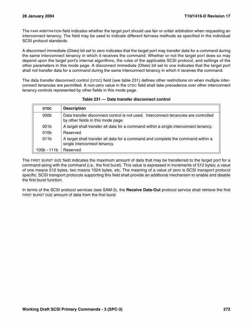
28 January 2004 T10/1416-D Revision 17
The FAIR ARBITRATION field indicates whether the target port should use fair or unfair arbitration when requesting aninterconnect tenancy. The field may be used to indicate different fairness methods as specified in the individualSCSI protocol standards.
A disconnect immediate (DIMM) bit set to zero indicates that the target port may transfer data for a command duringthe same interconnect tenancy in which it receives the command. Whether or not the target port does so maydepend upon the target port’s internal algorithms, the rules of the applicable SCSI protocol, and settings of theother parameters in this mode page. A disconnect immediate (DIMM) bit set to one indicates that the target portshall not transfer data for a command during the same interconnect tenancy in which it receives the command.
The data transfer disconnect control (DTDC) field (see table 231) defines other restrictions on when multiple inter-connect tenancies are permitted. A non-zero value in the DTDC field shall take precedence over other interconnecttenancy controls represented by other fields in this mode page.
The FIRST BURST SIZE field indicates the maximum amount of data that may be transferred to the target port for acommand along with the command (i.e., the first burst). This value is expressed in increments of 512 bytes; a valueof one means 512 bytes, two means 1024 bytes, etc. The meaning of a value of zero is SCSI transport protocolspecific. SCSI transport protocols supporting this field shall provide an additional mechanism to enable and disablethe first burst function.
In terms of the SCSI protocol services (see SAM-3), the Receive Data-Out protocol service shall retrieve the firstFIRST BURST SIZE amount of data from the first burst.
Table 231 — Data transfer disconnect control
DTDC Description
000b Data transfer disconnect control is not used. Interconnect tenancies are controlled by other fields in this mode page.
001b A target shall transfer all data for a command within a single interconnect tenancy.
010b Reserved
011b A target shall transfer all data for a command and complete the command within a single interconnect tenancy.
100b - 111b Reserved
Working Draft SCSI Primary Commands - 3 (SPC-3) 272
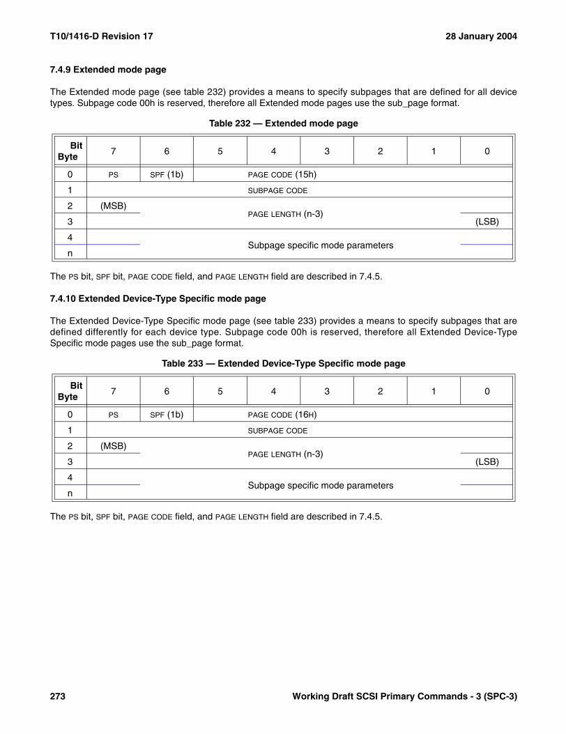
T10/1416-D Revision 17 28 January 2004
7.4.9 Extended mode page
The Extended mode page (see table 232) provides a means to specify subpages that are defined for all devicetypes. Subpage code 00h is reserved, therefore all Extended mode pages use the sub_page format.
The PS bit, SPF bit, PAGE CODE field, and PAGE LENGTH field are described in 7.4.5.
7.4.10 Extended Device-Type Specific mode page
The Extended Device-Type Specific mode page (see table 233) provides a means to specify subpages that aredefined differently for each device type. Subpage code 00h is reserved, therefore all Extended Device-TypeSpecific mode pages use the sub_page format.
The PS bit, SPF bit, PAGE CODE field, and PAGE LENGTH field are described in 7.4.5.
Table 232 — Extended mode page
BitByte
7 6 5 4 3 2 1 0
0 PS SPF (1b) PAGE CODE (15h)
1 SUBPAGE CODE
2 (MSB)PAGE LENGTH (n-3)
3 (LSB)
4Subpage specific mode parameters
n
Table 233 — Extended Device-Type Specific mode page
BitByte
7 6 5 4 3 2 1 0
0 PS SPF (1b) PAGE CODE (16H)
1 SUBPAGE CODE
2 (MSB)PAGE LENGTH (n-3)
3 (LSB)
4Subpage specific mode parameters
n
273 Working Draft SCSI Primary Commands - 3 (SPC-3)

28 January 2004 T10/1416-D Revision 17
7.4.11 Informational Exceptions Control mode page
The Informational Exceptions Control mode page (see table 234) defines the methods used by the target to controlthe reporting and the operations of specific informational exception conditions. This page shall only apply to infor-mational exceptions that report an additional sense code of FAILURE PREDICTION THRESHOLD EXCEEDED orWARNING to the application client. The mode page policy (see 6.7) for this mode page shall be shared, per initiatorport, or per I_T nexus.
Informational exception conditions occur as the result of vendor specific events within a target. An informationalexception condition may occur asynchronous to any commands issued by an application client.
NOTE 53 - Storage devices that support SMART (Self-Monitoring Analysis and Reporting Technology) forpredictive failure software should use informational exception conditions.
The PS bit, SPF bit, PAGE CODE field, and PAGE LENGTH field are described in 7.4.5.
The log errors (LOGERR) bit set to zero indicates that the logging of informational exception conditions by a deviceserver is vendor specific. A LOGERR bit set to one indicates the device server shall log informational exceptionconditions.
A TEST bit set to one shall create a test device failure at the next interval time, as specified by the INTERVAL TIMER
field, if the DEXCPT bit is set to zero. When the TEST bit is set to one, the MRIE and REPORT COUNT fields shall applyas if the TEST bit were zero. The test device failure shall be reported with an additional sense code of FAILUREPREDICTION THRESHOLD EXCEEDED (FALSE). If both the TEST and the DEXCPT bits are one, the device servershall terminate the MODE SELECT command with CHECK CONDITION status. The sense key shall be set toILLEGAL REQUEST with the additional sense code set to INVALID FIELD IN PARAMETER LIST. A TEST bit set tozero shall instruct the device server not to generate any test device failure notifications.
A disable exception control (DEXCPT) bit set to zero indicates the failure prediction threshold exceeded reportingshall be enabled. The method for reporting the failure prediction threshold exceeded when the DEXCPT bit is set tozero is determined from the MRIE field. A DEXCPT bit set to one indicates the target shall disable reporting of thefailure prediction threshold exceeded. The MRIE field is ignored when DEXCPT is set to one and EWASC is set tozero.
An enable warning (EWASC) bit set to zero indicates the target shall disable reporting of the warning. The MRIE fieldis ignored when DEXCPT is set to one and EWASC is set to zero. An EWASC bit set to one indicates warning
Table 234 — Informational Exceptions Control mode page
BitByte
7 6 5 4 3 2 1 0
0 PS SPF (0b) PAGE CODE (1Ch)
1 PAGE LENGTH (0Ah)
2 PERF Reserved EBF EWASC DEXCPT TEST Reserved LOGERR
3 Reserved MRIE
4 (MSB)INTERVAL TIMER
7 (LSB)
8 (MSB)REPORT COUNT
11 (LSB)
Working Draft SCSI Primary Commands - 3 (SPC-3) 274

T10/1416-D Revision 17 28 January 2004
reporting shall be enabled. The method for reporting the warning when the EWASC bit is set to one is determinedfrom the MRIE field.
If background functions are supported, an Enable Background Function (EBF) bit set to one indicates the targetshall enable background functions. An EBF bit set to zero indicates the target shall disable the functions.
For the purposes of the EBF bit, background functions are defined as idle time functions that may impact perfor-mance that are performed by a target operating without errors but do not impact the reliability of the target (e.g.,read scan).
A performance (PERF) bit set to zero indicates that informational exception operations that are the cause of delaysare acceptable. A PERF bit set to one indicates the device server shall not cause delays while doing informationalexception operations. A PERF bit set to one may cause the device server to disable some or all of the informationalexceptions operations, thereby limiting the reporting of informational exception conditions.
The method of reporting informational exceptions field (MRIE) indicates the methods that shall be used by thedevice server to report informational exception conditions (see table 235). The priority of reporting multiple infor-mation exceptions is vendor specific.
Table 235 — Method of reporting informational exceptions (MRIE) field (part 1 of 2)
MRIE Description
0h No reporting of informational exception condition: This method instructs the device server to not report information exception conditions.
1h Asynchronous event reporting: Obsolete
2h Generate unit attention: This method instructs the device server to report informational excep-tion conditions by returning a CHECK CONDITION status. The sense key shall be set to UNIT ATTENTION and the additional sense code shall indicate the cause of the informational excep-tion condition. The command that has the CHECK CONDITION shall not be executed before the informational exception condition is reported.
3h Conditionally generate recovered error: This method instructs the device server to report informational exception conditions, if the reporting of recovered errors is allowed, by returning a CHECK CONDITION status. If the TEST bit equals zero, the status may be returned after the informational exception condition occurs on any command for which GOOD status would have been returned. If the TEST bit equals one, the status shall be returned on the next command that is normally capable of returning an informational exception condition when the TEST bit equals zero. The sense key shall be set to RECOVERED ERROR and the additional sense code shall indicate the cause of the informational exception condition.
The command that returns the CHECK CONDITION for the informational exception shall com-plete without error before any informational exception condition may be reported.
a The Read-Write Error Recovery mode page is described in the applicable command standard (see 3.1.17).
275 Working Draft SCSI Primary Commands - 3 (SPC-3)

28 January 2004 T10/1416-D Revision 17
The INTERVAL TIMER field indicates the period in 100 millisecond increments for reporting that an informationalexception condition has occurred. The device server shall not report informational exception conditions morefrequently than the time specified by the INTERVAL TIMER field and shall report them after the time specified byINTERVAL TIMER field has elapsed. After the informational exception condition has been reported the interval timershall be restarted. A value of zero or FFFF FFFFh in the INTERVAL TIMER field shall indicate that the period forreporting an informational exception condition is vendor specific.
The REPORT COUNT field indicates the number of times to report an informational exception condition to the appli-cation client. A value of zero in the REPORT COUNT field indicates there is no limit on the number of times the deviceserver reports an informational exception condition.
The maintaining of the interval timer and the report counter across power cycles, hard resets, logical unit resets,and I_T nexus losses is vendor specific.
4h Unconditionally generate recovered error: This method instructs the device server to report informational exception conditions, regardless of the value of the post error (PER) bit of the
Read-Write Error Recovery mode page,a by returning a CHECK CONDITION status. If the TEST bit equals zero, the status may be returned after the informational exception condition occurs on any command for which GOOD status would have been returned. If the TEST bit equals one, the status shall be returned on the next command that is normally capable of returning an informa-tional exception condition when the TEST bit equals zero. The sense key shall be set to RECOV-ERED ERROR and the additional sense code shall indicate the cause of the informational exception condition.
The command that returns the CHECK CONDITION for the informational exception shall com-plete without error before any informational exception condition may be reported.
5h Generate no sense: This method instructs the device server to report informational exception conditions by returning a CHECK CONDITION status. If the TEST bit equals zero, the status may be returned after the informational exception condition occurs on any command for which GOOD status would have been returned. If the TEST bit equals one, the status shall be returned on the next command that is normally capable of returning an informational exception condition when the TEST bit equals zero. The sense key shall be set to NO SENSE and the additional sense code shall indicate the cause of the informational exception condition.
The command that returns the CHECK CONDITION for the informational exception shall com-plete without error before any informational exception condition may be reported.
6h Only report informational exception condition on request: This method instructs the device server to preserve the informational exception(s) information. To find out about information exception conditions the application client polls the device server by issuing a REQUEST SENSE command. The sense key shall be set to NO SENSE and the additional sense code shall indicate the cause of the informational exception condition.
7h - Bh Reserved
Ch - Fh Vendor specific
Table 235 — Method of reporting informational exceptions (MRIE) field (part 2 of 2)
MRIE Description
a The Read-Write Error Recovery mode page is described in the applicable command standard (see 3.1.17).
Working Draft SCSI Primary Commands - 3 (SPC-3) 276

T10/1416-D Revision 17 28 January 2004
7.4.12 Power Condition mode page
The Power Condition mode page provides an application client the methods to control the power condition of alogical unit (see 5.9). These methods include:
a) Specifying that the logical unit transition to a power condition without delay; andb) Activating and setting of idle condition and standby condition timers to specify that the logical unit wait for a
period of inactivity before transitioning to a specified power condition.
The mode page policy (see 6.7) for this mode page shall be shared.
When a device server receives a command while in a power condition based on a setting in the Power Conditionmode page, the logical unit shall transition to the power condition that allows the command to be processed. Ifeither the idle condition timer or the standby condition timer has been set, they shall be reset on receipt of thecommand. On completion of the command, the timer(s) shall be started.
Logical units that contain cache memory shall write all cached data to the medium for the logical unit (e.g.,as alogical unit would do in response to a SYNCHRONIZE CACHE command as described in SBC-2) prior to enteringinto any power condition that prevents accessing the media (e.g., before a hard drive stops its spindle motor duringtransition to the standby power condition).
The logical unit shall use the values in the Power Condition mode page to control its power condition after a poweron or a hard reset until a START STOP UNIT command setting a power condition is received.
Table 236 defines the Power Condition mode page.
The PS bit, SPF bit, PAGE CODE field, and PAGE LENGTH field are described in 7.4.5.
The IDLE and STANDBY bits specify which timers are active.
If the IDLE bit is set to one and the STANDBY bit is set to zero, then the idle condition timer is active and the deviceserver shall transition to the idle power condition when the idle condition timer is zero.
If the IDLE bit is set to zero, then the device server shall ignore the idle condition timer.
If the STANDBY bit is set to one and the IDLE bit is set to zero, then the standby condition timer is active and thedevice server shall transition to the standby power condition when the standby condition timer is zero.
Table 236 — Power Condition mode page
BitByte
7 6 5 4 3 2 1 0
0 PS SPF (0b) PAGE CODE (1Ah)
1 PAGE LENGTH (0Ah)
2 Reserved
3 Reserved IDLE STANDBY
4 (MSB)IDLE CONDITION TIMER
7 (LSB)
8 (MSB)STANDBY CONDITION TIMER
11 (LSB)
277 Working Draft SCSI Primary Commands - 3 (SPC-3)

28 January 2004 T10/1416-D Revision 17
If the STANDBY bit is set to zero, then the device server shall ignore the standby condition timer.
If both the IDLE and STANDBY bits are set to one, then both timers are active and run concurrently. When the idlecondition timer is zero the device server shall transition to the idle power condition. When the standby conditiontimer is zero the device server shall transition to the standby power condition. If the standby condition timer is zerobefore the idle condition timer is zero, then the logical unit shall transition to the standby power condition.
The value in the IDLE CONDITION TIMER field specifies the inactivity time in 100 millisecond increments that thelogical unit shall wait before transitioning to the idle power condition when the IDLE bit is set to one. The idlecondition timer is expired when:
a) The IDLE CONDITION TIMER field is set to zero; orb) The number of milliseconds specified by the value in the IDLE CONDITION TIMER field times 100 milliseconds
has elapsed since the last activity.
The value in the STANDBY CONDITION TIMER field specifies the inactivity time in 100 millisecond increments that thelogical unit shall wait before transitioning to the standby power condition when the STANDBY bit is set to one. Thestandby condition timer is expired when:
a) The STANDBY CONDITION TIMER field is set to zero; orb) The number of milliseconds specified by the value in the STANDBY CONDITION TIMER field times 100 milli-
seconds has elapsed since the last activity.
7.4.13 Protocol Specific Logical Unit mode page
The Protocol Specific Logical Unit mode page (see table 237) provides protocol specific controls that are asso-ciated with a logical unit.
During an I_T_L nexus, the Protocol Specific Logical Unit mode page controls parameters that affect both:
a) One or more target ports; and b) The logical unit.
The parameters that may be implemented are specified in the SCSI transport protocol standard (see 3.1.76) for thetarget port. The mode page policy (see 6.7) for this mode page shall be shared or per target port and should be pertarget port. If a logical unit is accessible through multiple target ports, changes in the parameters for one target portshould not affect other target ports.
The parameters for a target port and logical unit affect their behavior regardless of which initiator port is forming anI_T_L nexus with the target port and logical unit. If a parameter value is changed, the logical unit shall establish aunit attention condition with an additional sense code of MODE PARAMETERS CHANGED for all initiator ports thatform I_T_L nexuses through that target port other than the initiator port which made the change.
Table 237 — Protocol Specific Logical Unit mode page
BitByte
7 6 5 4 3 2 1 0
0 PS SPF (0b) PAGE CODE (18H)
1 PAGE LENGTH (n-1)
2 Reserved PROTOCOL IDENTIFIER
3Protocol specific mode parameters
n
Working Draft SCSI Primary Commands - 3 (SPC-3) 278

T10/1416-D Revision 17 28 January 2004
The PS bit, SPF bit, PAGE CODE field, and PAGE LENGTH field are described in 7.4.5.
The PROTOCOL IDENTIFIER field (see 7.5.1) indicates the SCSI transport protocol to which the mode page applies.For a MODE SENSE command (see 6.9), the device server shall set the PROTOCOL IDENTIFIER field to one of thevalues shown in table 240 (see 7.5.1) to indicate the SCSI transport protocol used by the target port through whichthe MODE SENSE command is being processed. For a MODE SELECT command (see 6.7), the application clientshall set the PROTOCOL IDENTIFIER field to one of the values shown in table 240 indicating the SCSI transportprotocol to which the protocol specific mode parameters apply. If a device server receives a mode page containinga transport protocol identifier value other than the one used by the target port through which the MODE SELECTcommand is being processed, it shall terminate the command with a CHECK CONDITION status. The sense keyshall be set to ILLEGAL REQUEST and the additional sense code shall be set to INVALID FIELD IN PARAMETERLIST.
7.4.14 Protocol Specific Port mode page
The Protocol Specific Port mode page provides protocol specific controls that are associated with a SCSI port. Thepage_0 format (see table 238) is used for subpage 00h and sub_page format (see table 239) is used for subpages01h through FEh. See the SCSI protocol standard (see 3.1.76) for definition of the protocol specific mode param-eters.
The Protocol Specific Port mode page controls parameters that affect one or more target ports. The parametersthat may be implemented are specified in the SCSI transport protocol standard (see 3.1.76) for the target port. Themode page policy (see 6.7) for this mode page shall be shared or per target port and should be per target port. If atarget device has multiple target ports, changes in the parameters for one target port should not affect other targetports.
Table 238 — Page_0 format Protocol Specific Port mode page
BitByte
7 6 5 4 3 2 1 0
0 PS SPF (0b) PAGE CODE (19H)
1 PAGE LENGTH (n-1)
2 Reserved PROTOCOL IDENTIFIER
3Protocol specific mode parameters
n
Table 239 — Sub_page format Protocol Specific Port mode page
BitByte
7 6 5 4 3 2 1 0
0 PS SPF (1b) PAGE CODE (19H)
1 SUBPAGE CODE
2 (MSB)PAGE LENGTH (n-3)
3 (LSB)
4 Reserved
5 Reserved PROTOCOL IDENTIFIER
6Protocol specific mode parameters
n
279 Working Draft SCSI Primary Commands - 3 (SPC-3)
28 January 2004 T10/1416-D Revision 17
The parameters for a target port affect its behavior regardless of which initiator port is forming an I_T nexus withthe target port. The parameters may be accessed by MODE SENSE (see 6.9) and MODE SELECT (see 6.7)commands directed to any logical unit accessible through the target port. If a parameter value is changed, alllogical units accessible through the target port shall establish a unit attention condition with an additional sensecode of MODE PARAMETERS CHANGED for all initiator ports that form I_T_L nexuses through that target portexcept the initiator port which made the change.
The PS bit, SPF bit, PAGE CODE field, SUBPAGE CODE field, and PAGE LENGTH field are described in 7.4.5.
The PROTOCOL IDENTIFIER field (see 7.5.1) indicates the SCSI transport protocol to which the mode page applies.For a MODE SENSE command, the device server shall set the PROTOCOL IDENTIFIER field to one of the valuesshown in table 240 (see 7.5.1) to indicate the SCSI transport protocol used by the target port through which theMODE SENSE command is being processed. For a MODE SELECT command, the application client shall set thePROTOCOL IDENTIFIER field to one of the values shown in table 240 indicating the SCSI transport protocol to whichthe protocol specific mode parameters apply. If a device server receives a mode page containing a transportprotocol identifier value other than the one used by the target port through which the MODE SELECT command isbeing processed, it shall terminate the command with a CHECK CONDITION status. The sense key shall be set toILLEGAL REQUEST and the additional sense code shall be set to INVALID FIELD IN PARAMETER LIST.
Working Draft SCSI Primary Commands - 3 (SPC-3) 280
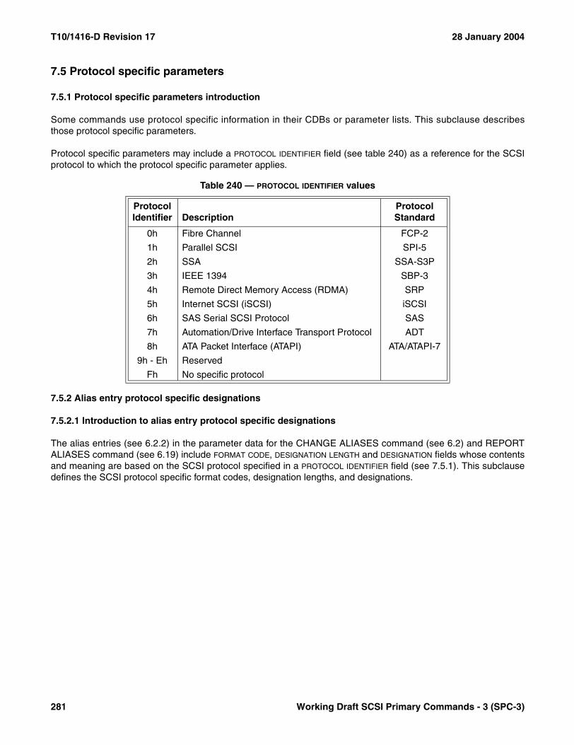
T10/1416-D Revision 17 28 January 2004
7.5 Protocol specific parameters
7.5.1 Protocol specific parameters introduction
Some commands use protocol specific information in their CDBs or parameter lists. This subclause describesthose protocol specific parameters.
Protocol specific parameters may include a PROTOCOL IDENTIFIER field (see table 240) as a reference for the SCSIprotocol to which the protocol specific parameter applies.
7.5.2 Alias entry protocol specific designations
7.5.2.1 Introduction to alias entry protocol specific designations
The alias entries (see 6.2.2) in the parameter data for the CHANGE ALIASES command (see 6.2) and REPORTALIASES command (see 6.19) include FORMAT CODE, DESIGNATION LENGTH and DESIGNATION fields whose contentsand meaning are based on the SCSI protocol specified in a PROTOCOL IDENTIFIER field (see 7.5.1). This subclausedefines the SCSI protocol specific format codes, designation lengths, and designations.
Table 240 — PROTOCOL IDENTIFIER values
Protocol Identifier Description
Protocol Standard
0h Fibre Channel FCP-2
1h Parallel SCSI SPI-5
2h SSA SSA-S3P
3h IEEE 1394 SBP-3
4h Remote Direct Memory Access (RDMA) SRP
5h Internet SCSI (iSCSI) iSCSI
6h SAS Serial SCSI Protocol SAS
7h Automation/Drive Interface Transport Protocol ADT
8h ATA Packet Interface (ATAPI) ATA/ATAPI-7
9h - Eh Reserved
Fh No specific protocol
281 Working Draft SCSI Primary Commands - 3 (SPC-3)

28 January 2004 T10/1416-D Revision 17
7.5.2.2 Fibre Channel specific alias entry designations
7.5.2.2.1 Introduction to Fibre Channel specific alias entry designations
If an alias entry PROTOCOL IDENTIFIER field specifies the Fibre Channel protocol (0h, see table 240), the FORMAT
CODE, DESIGNATION LENGTH and DESIGNATION fields shall be as defined in table 241.
7.5.2.2.2 Fibre Channel world wide port name alias entry designation
If the PROTOCOL IDENTIFIER and FORMAT CODE fields specify a Fibre Channel world wide port name designation, thealias entry DESIGNATION field shall have the format shown in table 242.
The FIBRE CHANNEL WORLD WIDE PORT NAME field shall contain the port world wide name defined by the port login(PLOGI) extended link service (see FC-FS).
A Fibre Channel world wide port name designation is valid (see 6.2.3) if the device server has access to a SCSIdomain formed by a Fibre Channel fabric and the fabric contains a port with the specified port world wide name.
7.5.2.2.3 Fibre Channel world wide port name with N_Port checking alias entry designation
If the PROTOCOL IDENTIFIER and FORMAT CODE fields specify a Fibre Channel world wide port name with N_Portchecking designation, the alias entry DESIGNATION field shall have the format shown in table 243.
Table 241 — Fibre Channel alias entry format codes
Format Code Description
Designation Length (bytes)
Designation Subclause
00h World Wide Port Name 8 7.5.2.2.2
01h World Wide Port Name with N_Port checking
12 7.5.2.2.3
02h - FFh Reserved
Table 242 — Fibre Channel world wide port name alias entry designation
BitByte
7 6 5 4 3 2 1 0
16FIBRE CHANNEL WORLD WIDE PORT NAME
23
Table 243 — Fibre Channel world wide port name with N_Port checking alias entry designation
BitByte
7 6 5 4 3 2 1 0
16FIBRE CHANNEL WORLD WIDE PORT NAME
23
24 Reserved
25 (MSB)N_PORT
27 (LSB)
Working Draft SCSI Primary Commands - 3 (SPC-3) 282
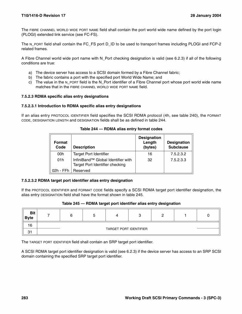
T10/1416-D Revision 17 28 January 2004
The FIBRE CHANNEL WORLD WIDE PORT NAME field shall contain the port world wide name defined by the port login(PLOGI) extended link service (see FC-FS).
The N_PORT field shall contain the FC_FS port D_ID to be used to transport frames including PLOGI and FCP-2related frames.
A Fibre Channel world wide port name with N_Port checking designation is valid (see 6.2.3) if all of the followingconditions are true:
a) The device server has access to a SCSI domain formed by a Fibre Channel fabric;b) The fabric contains a port with the specified port World Wide Name; andc) The value in the N_PORT field is the N_Port identifier of a Fibre Channel port whose port world wide name
matches that in the FIBRE CHANNEL WORLD WIDE PORT NAME field.
7.5.2.3 RDMA specific alias entry designations
7.5.2.3.1 Introduction to RDMA specific alias entry designations
If an alias entry PROTOCOL IDENTIFIER field specifies the SCSI RDMA protocol (4h, see table 240), the FORMAT
CODE, DESIGNATION LENGTH and DESIGNATION fields shall be as defined in table 244.
7.5.2.3.2 RDMA target port identifier alias entry designation
If the PROTOCOL IDENTIFIER and FORMAT CODE fields specify a SCSI RDMA target port identifier designation, thealias entry DESIGNATION field shall have the format shown in table 245.
The TARGET PORT IDENTIFIER field shall contain an SRP target port identifier.
A SCSI RDMA target port identifier designation is valid (see 6.2.3) if the device server has access to an SRP SCSIdomain containing the specified SRP target port identifier.
Table 244 — RDMA alias entry format codes
Format Code Description
Designation Length (bytes)
Designation Subclause
00h Target Port Identifier 16 7.5.2.3.2
01h InfiniBand™ Global Identifier with Target Port Identifier checking
32 7.5.2.3.3
02h - FFh Reserved
Table 245 — RDMA target port identifier alias entry designation
BitByte
7 6 5 4 3 2 1 0
16TARGET PORT IDENTIFIER
31
283 Working Draft SCSI Primary Commands - 3 (SPC-3)
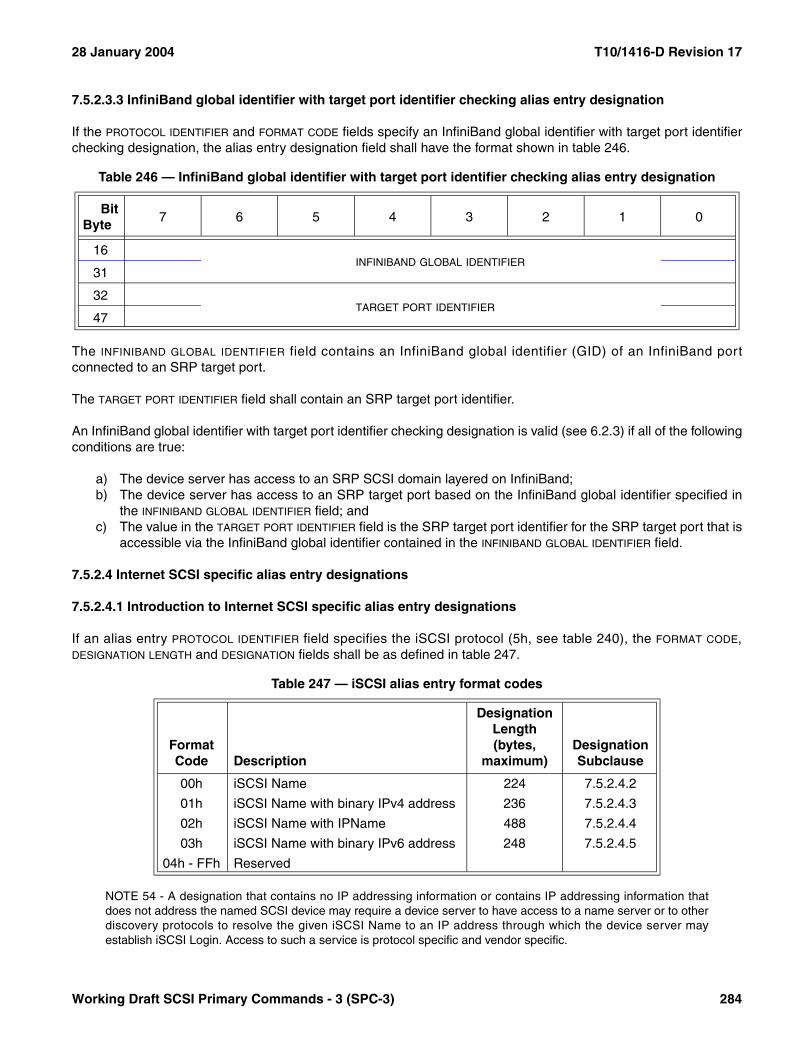
28 January 2004 T10/1416-D Revision 17
7.5.2.3.3 InfiniBand global identifier with target port identifier checking alias entry designation
If the PROTOCOL IDENTIFIER and FORMAT CODE fields specify an InfiniBand global identifier with target port identifierchecking designation, the alias entry designation field shall have the format shown in table 246.
The INFINIBAND GLOBAL IDENTIFIER field contains an InfiniBand global identifier (GID) of an InfiniBand portconnected to an SRP target port.
The TARGET PORT IDENTIFIER field shall contain an SRP target port identifier.
An InfiniBand global identifier with target port identifier checking designation is valid (see 6.2.3) if all of the followingconditions are true:
a) The device server has access to an SRP SCSI domain layered on InfiniBand;b) The device server has access to an SRP target port based on the InfiniBand global identifier specified in
the INFINIBAND GLOBAL IDENTIFIER field; andc) The value in the TARGET PORT IDENTIFIER field is the SRP target port identifier for the SRP target port that is
accessible via the InfiniBand global identifier contained in the INFINIBAND GLOBAL IDENTIFIER field.
7.5.2.4 Internet SCSI specific alias entry designations
7.5.2.4.1 Introduction to Internet SCSI specific alias entry designations
If an alias entry PROTOCOL IDENTIFIER field specifies the iSCSI protocol (5h, see table 240), the FORMAT CODE,DESIGNATION LENGTH and DESIGNATION fields shall be as defined in table 247.
NOTE 54 - A designation that contains no IP addressing information or contains IP addressing information thatdoes not address the named SCSI device may require a device server to have access to a name server or to otherdiscovery protocols to resolve the given iSCSI Name to an IP address through which the device server mayestablish iSCSI Login. Access to such a service is protocol specific and vendor specific.
Table 246 — InfiniBand global identifier with target port identifier checking alias entry designation
BitByte
7 6 5 4 3 2 1 0
16INFINIBAND GLOBAL IDENTIFIER
31
32TARGET PORT IDENTIFIER
47
Table 247 — iSCSI alias entry format codes
Format Code Description
Designation Length (bytes,
maximum)Designation Subclause
00h iSCSI Name 224 7.5.2.4.2
01h iSCSI Name with binary IPv4 address 236 7.5.2.4.3
02h iSCSI Name with IPName 488 7.5.2.4.4
03h iSCSI Name with binary IPv6 address 248 7.5.2.4.5
04h - FFh Reserved
Working Draft SCSI Primary Commands - 3 (SPC-3) 284

T10/1416-D Revision 17 28 January 2004
7.5.2.4.2 iSCSI name alias entry designation
If the PROTOCOL IDENTIFIER and FORMAT CODE fields specify iSCSI name designation, the alias entry DESIGNATION
field shall have the format shown in table 248.
The null-terminated, null-padded (see 4.4.2) ISCSI NAME field shall contain the iSCSI name of an iSCSI node (seedraft-ietf-ips-iscsi-16.txt). The number of bytes in the ISCSI NAME field shall be a multiple of four.
An iSCSI name designation is valid if the device server has access to a SCSI domain containing an Internetprotocol network and that network contains an iSCSI node with the specified iSCSI name.
7.5.2.4.3 iSCSI name with binary IPv4 address alias entry designation
If the PROTOCOL IDENTIFIER and FORMAT CODE fields specify iSCSI name with binary IPv4 address designation, thealias entry DESIGNATION field shall have the format shown in table 249.
The null-terminated, null-padded (see 4.4.2) ISCSI NAME field shall contain the iSCSI name of an iSCSI node (seedraft-ietf-ips-iscsi-16.txt). The number of bytes in the ISCSI NAME field shall be a multiple of four.
The IPV4 ADDRESS field shall contain an IPv4 address (see RFC 791).
The PORT NUMBER field shall contain a port number (see RFC 790).
The INTERNET PROTOCOL NUMBER field shall contain an Internet protocol number (see RFC 790).
Table 248 — iSCSI name alias entry designation
BitByte
7 6 5 4 3 2 1 0
16 (MSB)ISCSI NAME
4m-1 (LSB)
Table 249 — iSCSI name with binary IPv4 address alias entry designation
BitByte
7 6 5 4 3 2 1 0
16 (MSB)ISCSI NAME
4m-1 (LSB)
4m (MSB)IPV4 ADDRESS
4m+3 (LSB)
4m+4 Reserved
4m+5 Reserved
4m+6 (MSB)PORT NUMBER
4m+7 (LSB)
4m+8 Reserved
4m+9 Reserved
4m+10 (MSB)INTERNET PROTOCOL NUMBER
4m+11 (LSB)
285 Working Draft SCSI Primary Commands - 3 (SPC-3)
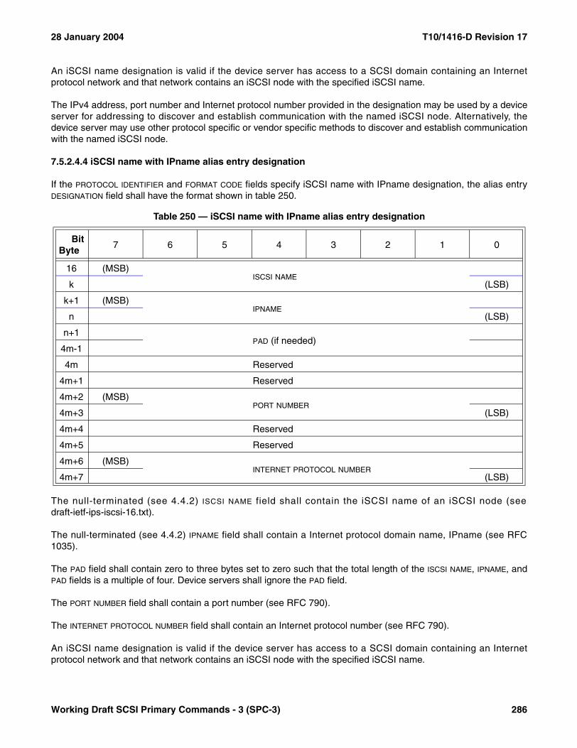
28 January 2004 T10/1416-D Revision 17
An iSCSI name designation is valid if the device server has access to a SCSI domain containing an Internetprotocol network and that network contains an iSCSI node with the specified iSCSI name.
The IPv4 address, port number and Internet protocol number provided in the designation may be used by a deviceserver for addressing to discover and establish communication with the named iSCSI node. Alternatively, thedevice server may use other protocol specific or vendor specific methods to discover and establish communicationwith the named iSCSI node.
7.5.2.4.4 iSCSI name with IPname alias entry designation
If the PROTOCOL IDENTIFIER and FORMAT CODE fields specify iSCSI name with IPname designation, the alias entryDESIGNATION field shall have the format shown in table 250.
The null-terminated (see 4.4.2) ISCSI NAME field shall contain the iSCSI name of an iSCSI node (seedraft-ietf-ips-iscsi-16.txt).
The null-terminated (see 4.4.2) IPNAME field shall contain a Internet protocol domain name, IPname (see RFC1035).
The PAD field shall contain zero to three bytes set to zero such that the total length of the ISCSI NAME, IPNAME, andPAD fields is a multiple of four. Device servers shall ignore the PAD field.
The PORT NUMBER field shall contain a port number (see RFC 790).
The INTERNET PROTOCOL NUMBER field shall contain an Internet protocol number (see RFC 790).
An iSCSI name designation is valid if the device server has access to a SCSI domain containing an Internetprotocol network and that network contains an iSCSI node with the specified iSCSI name.
Table 250 — iSCSI name with IPname alias entry designation
BitByte
7 6 5 4 3 2 1 0
16 (MSB)ISCSI NAME
k (LSB)
k+1 (MSB)IPNAME
n (LSB)
n+1PAD (if needed)
4m-1
4m Reserved
4m+1 Reserved
4m+2 (MSB)PORT NUMBER
4m+3 (LSB)
4m+4 Reserved
4m+5 Reserved
4m+6 (MSB)INTERNET PROTOCOL NUMBER
4m+7 (LSB)
Working Draft SCSI Primary Commands - 3 (SPC-3) 286

T10/1416-D Revision 17 28 January 2004
The Internet protocol domain name, port number and Internet protocol number provided in the designation may beused by a device server for addressing to discover and establish communication with the named iSCSI node. Alter-natively, the device server may use other protocol specific or vendor specific methods to discover and establishcommunication with the named iSCSI node.
7.5.2.4.5 iSCSI name with binary IPv6 address alias entry designation
If the PROTOCOL IDENTIFIER and FORMAT CODE fields specify iSCSI name with binary IPv6 address designation, thealias entry DESIGNATION field shall have the format shown in table 249.
The null-terminated, null-padded (see 4.4.2) ISCSI NAME field shall contain the iSCSI name of an iSCSI node (seedraft-ietf-ips-iscsi-16.txt).
The IPV6 ADDRESS field shall contain an IPv6 address (see RFC 2373).
The PORT NUMBER field shall contain a port number (see RFC 790).
The INTERNET PROTOCOL NUMBER field shall contain an Internet protocol number (see RFC 790).
An iSCSI name designation is valid if the device server has access to a SCSI domain containing an Internetprotocol network and that network contains an iSCSI node with the specified iSCSI name.
The IPv6 address, port number and Internet protocol number provided in the designation may be used by a deviceserver for addressing to discover and establish communication with the named iSCSI node. Alternatively, thedevice server may use other protocol specific or vendor specific methods to discover and establish communicationwith the named iSCSI node.
Table 251 — iSCSI name with binary IPv6 address alias entry designation
BitByte
7 6 5 4 3 2 1 0
16 (MSB)ISCSI NAME
n (LSB)
4m (MSB)IPV6 ADDRESS
4m+15 (LSB)
4m+16 Reserved
4m+17 Reserved
4m+18 (MSB)PORT NUMBER
4m+19 (LSB)
4m+20 Reserved
4m+21 Reserved
4m+22 (MSB)INTERNET PROTOCOL NUMBER
4m+23 (LSB)
287 Working Draft SCSI Primary Commands - 3 (SPC-3)

28 January 2004 T10/1416-D Revision 17
7.5.3 EXTENDED COPY protocol specific target descriptors
7.5.3.1 Introduction to EXTENDED COPY protocol specific target descriptors
The target descriptors present in the parameter data of the EXTENDED COPY command (see 6.3) may haveprotocol specific formats described in this subclause. An introduction to EXTENDED COPY target descriptors isprovided in 6.3.6.1.
NOTE 55 - In the EXTENDED COPY command the target in target descriptor refers to a copy target device (i.e.,the source or destination of an EXTENDED COPY operation). EXTENDED COPY target descriptors may specifySCSI target devices, not SCSI target ports.
7.5.3.2 Fibre Channel world wide name EXTENDED COPY target descriptor format
The target descriptor format shown in table 252 is used by an EXTENDED COPY command to specify a copytarget device using its Fibre Channel world wide name.
The DESCRIPTOR TYPE CODE, LU ID TYPE, PERIPHERAL DEVICE TYPE, NUL and LU IDENTIFIER fields and the device typespecific parameters are described in 6.3.6.1.
The WORLD WIDE NAME field shall contain the port world wide name defined by the port login (PLOGI) extended linkservice (see FC-FS).
NOTE 56 - The world wide name target descriptor format necessitates translating the world wide name to anN_Port identifier (see 7.5.3.3).
Table 252 — Fibre Channel world wide name EXTENDED COPY target descriptor format
BitByte
7 6 5 4 3 2 1 0
0 DESCRIPTOR TYPE CODE (E0h)
1 LU ID TYPE NUL PERIPHERAL DEVICE TYPE
2 Reserved
3 Reserved
4LU IDENTIFIER
11
12WORLD WIDE NAME
19
20Reserved
27
28Device type specific parameters
31
Working Draft SCSI Primary Commands - 3 (SPC-3) 288
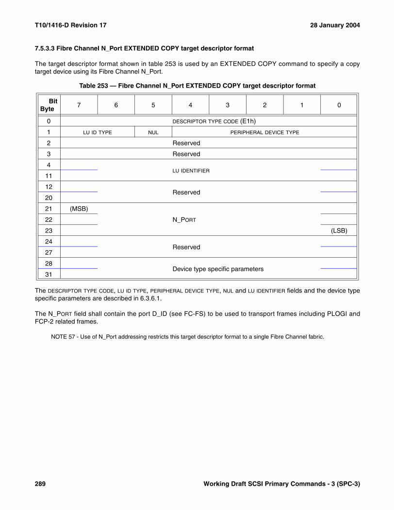
T10/1416-D Revision 17 28 January 2004
7.5.3.3 Fibre Channel N_Port EXTENDED COPY target descriptor format
The target descriptor format shown in table 253 is used by an EXTENDED COPY command to specify a copytarget device using its Fibre Channel N_Port.
The DESCRIPTOR TYPE CODE, LU ID TYPE, PERIPHERAL DEVICE TYPE, NUL and LU IDENTIFIER fields and the device typespecific parameters are described in 6.3.6.1.
The N_PORT field shall contain the port D_ID (see FC-FS) to be used to transport frames including PLOGI andFCP-2 related frames.
NOTE 57 - Use of N_Port addressing restricts this target descriptor format to a single Fibre Channel fabric.
Table 253 — Fibre Channel N_Port EXTENDED COPY target descriptor format
BitByte
7 6 5 4 3 2 1 0
0 DESCRIPTOR TYPE CODE (E1h)
1 LU ID TYPE NUL PERIPHERAL DEVICE TYPE
2 Reserved
3 Reserved
4LU IDENTIFIER
11
12Reserved
20
21 (MSB)
N_PORT22
23 (LSB)
24Reserved
27
28Device type specific parameters
31
289 Working Draft SCSI Primary Commands - 3 (SPC-3)

28 January 2004 T10/1416-D Revision 17
7.5.3.4 Fibre Channel N_Port with world wide name checking EXTENDED COPY target descriptor format
EXTENDED COPY command copy target devices that are addressed using their Fibre Channel N_Port with WorldWide Name checking use the target descriptor format shown in table 254 to specify the addressing information.
The DESCRIPTOR TYPE CODE, LU ID TYPE, PERIPHERAL DEVICE TYPE, NUL and LU IDENTIFIER fields and the device typespecific parameters are described in 6.3.6.1.
The WORLD WIDE NAME field shall contain the port world wide name defined by the port login (PLOGI) extended linkservice (see FC-FS).
The N_PORT field shall contain the port D_ID (see FC-FS) to be used to transport frames including PLOGI andFCP-2 related frames.
NOTE 58 - Use of N_Port addressing restricts this target descriptor format to a single fabric.
When the copy manager first processes a segment descriptor that references this target descriptor, it shall confirmthat the D_ID in the N_PORT field is associated with the world wide name in the WORLD WIDE NAME field. If theconfirmation fails, the command shall be terminated because the target is unavailable (see 6.3.3). The SCSI deviceprocessing this target descriptor shall track configuration changes that affect the D_ID value for the duration of thetask. An application client is responsible for tracking configuration changes between commands.
Table 254 — Fibre Channel N_Port with world wide name checking target descriptor format
BitByte
7 6 5 4 3 2 1 0
0 DESCRIPTOR TYPE CODE (E2h)
1 LU ID TYPE NUL PERIPHERAL DEVICE TYPE
2 Reserved
3 Reserved
4LU IDENTIFIER
11
12WORLD WIDE NAME
19
20 Reserved
21 (MSB)
N_PORT22
23 (LSB)
24Reserved
27
28Device type specific parameters
31
Working Draft SCSI Primary Commands - 3 (SPC-3) 290
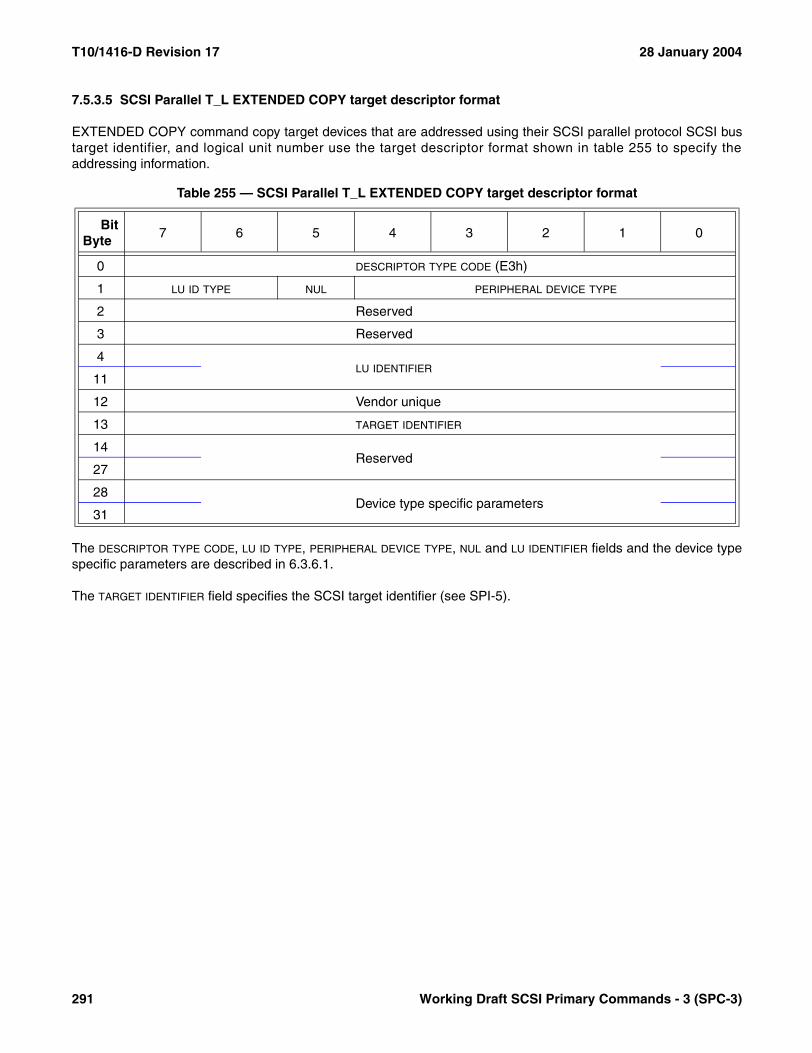
T10/1416-D Revision 17 28 January 2004
7.5.3.5 SCSI Parallel T_L EXTENDED COPY target descriptor format
EXTENDED COPY command copy target devices that are addressed using their SCSI parallel protocol SCSI bustarget identifier, and logical unit number use the target descriptor format shown in table 255 to specify theaddressing information.
The DESCRIPTOR TYPE CODE, LU ID TYPE, PERIPHERAL DEVICE TYPE, NUL and LU IDENTIFIER fields and the device typespecific parameters are described in 6.3.6.1.
The TARGET IDENTIFIER field specifies the SCSI target identifier (see SPI-5).
Table 255 — SCSI Parallel T_L EXTENDED COPY target descriptor format
BitByte
7 6 5 4 3 2 1 0
0 DESCRIPTOR TYPE CODE (E3h)
1 LU ID TYPE NUL PERIPHERAL DEVICE TYPE
2 Reserved
3 Reserved
4LU IDENTIFIER
11
12 Vendor unique
13 TARGET IDENTIFIER
14Reserved
27
28Device type specific parameters
31
291 Working Draft SCSI Primary Commands - 3 (SPC-3)

28 January 2004 T10/1416-D Revision 17
7.5.3.6 IEEE 1394 EUI-64 EXTENDED COPY target descriptor format
The target descriptor format shown in table 256 is used to identify an EXTENDED COPY command copy targetdevice using its IEEE 1394 Extended Unique Identifier, 64-bits (EUI-64) and configuration ROM (Read-OnlyMemory) directory identifier.
The DESCRIPTOR TYPE CODE, LU ID TYPE, PERIPHERAL DEVICE TYPE, NUL and LU IDENTIFIER fields and the device typespecific parameters are described in 6.3.6.1.
The EUI-64 field shall contain the node’s unique identifier (EUI-64) obtained from the configuration ROM bus infor-mation block, as specified by IEEE 1394a:2000.
NOTE 59 - IEEE 1394a-2000 separately labels the components of the EUI-64 as NODE_VENDOR_ID, CHIP_ID_HI andCHIP_ID_LO. Collectively these form the node’s EUI-64.
The DIRECTORY ID field shall contain the copy target device’s directory identifier, as specified by ISO/IEC13213:1994.
Table 256 — IEEE 1394 EUI-64 EXTENDED COPY target descriptor format
BitByte
7 6 5 4 3 2 1 0
0 DESCRIPTOR TYPE CODE (E8h)
1 LU ID TYPE NUL PERIPHERAL DEVICE TYPE
2 Reserved
3 Reserved
4LU IDENTIFIER
11
12EUI-64
19
20DIRECTORY ID
22
23Reserved
27
28Device type specific parameters
31
Working Draft SCSI Primary Commands - 3 (SPC-3) 292
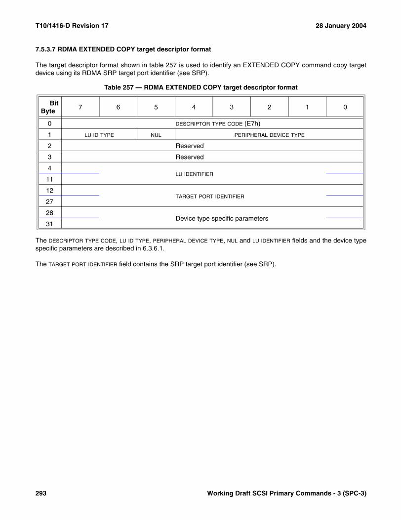
T10/1416-D Revision 17 28 January 2004
7.5.3.7 RDMA EXTENDED COPY target descriptor format
The target descriptor format shown in table 257 is used to identify an EXTENDED COPY command copy targetdevice using its RDMA SRP target port identifier (see SRP).
The DESCRIPTOR TYPE CODE, LU ID TYPE, PERIPHERAL DEVICE TYPE, NUL and LU IDENTIFIER fields and the device typespecific parameters are described in 6.3.6.1.
The TARGET PORT IDENTIFIER field contains the SRP target port identifier (see SRP).
Table 257 — RDMA EXTENDED COPY target descriptor format
BitByte
7 6 5 4 3 2 1 0
0 DESCRIPTOR TYPE CODE (E7h)
1 LU ID TYPE NUL PERIPHERAL DEVICE TYPE
2 Reserved
3 Reserved
4LU IDENTIFIER
11
12TARGET PORT IDENTIFIER
27
28Device type specific parameters
31
293 Working Draft SCSI Primary Commands - 3 (SPC-3)

28 January 2004 T10/1416-D Revision 17
7.5.3.8 iSCSI binary IPv4 address EXTENDED COPY target descriptor format
EXTENDED COPY command copy target devices that are addressed using their Internet protocol binary IPv4address, and logical unit number use the target descriptor format shown in table 258 to specify the addressinginformation.
The DESCRIPTOR TYPE CODE, LU ID TYPE, PERIPHERAL DEVICE TYPE, NUL and LU IDENTIFIER fields and the device typespecific parameters are described in 6.3.6.1.
The IPV4 ADDRESS field shall contain an IPv4 address (see RFC 791).
The PORT NUMBER field shall contain the port number (see RFC 790).
The INTERNET PROTOCOL NUMBER field shall contain an Internet protocol number (see RFC 790).
Table 258 — iSCSI binary IPv4 address EXTENDED COPY target descriptor format
BitByte
7 6 5 4 3 2 1 0
0 DESCRIPTOR TYPE CODE (E5h)
1 LU ID TYPE NUL PERIPHERAL DEVICE TYPE
2 Reserved
3 Reserved
4LU IDENTIFIER
11
12 (MSB)IPV4 ADDRESS
15 (LSB)
16Reserved
21
22 (MSB)PORT NUMBER
23 (LSB)
24 Reserved
25 Reserved
26 (MSB)INTERNET PROTOCOL NUMBER
27 (LSB)
28Device type specific parameters
31
Working Draft SCSI Primary Commands - 3 (SPC-3) 294
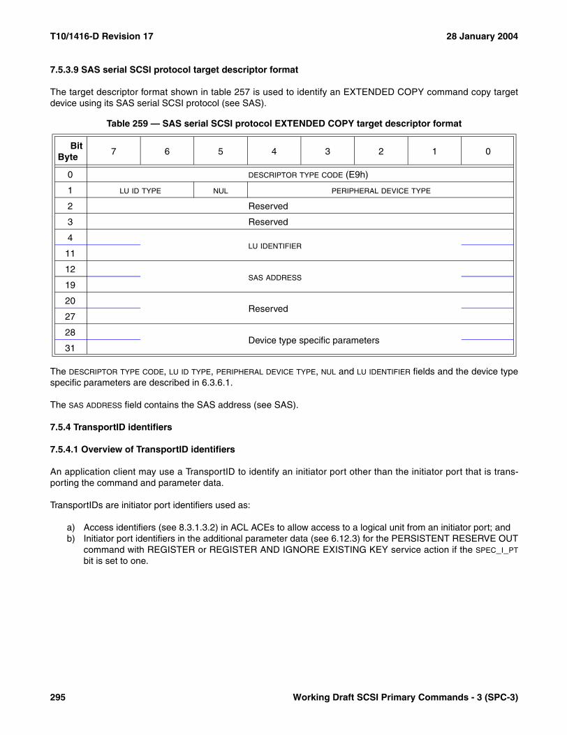
T10/1416-D Revision 17 28 January 2004
7.5.3.9 SAS serial SCSI protocol target descriptor format
The target descriptor format shown in table 257 is used to identify an EXTENDED COPY command copy targetdevice using its SAS serial SCSI protocol (see SAS).
The DESCRIPTOR TYPE CODE, LU ID TYPE, PERIPHERAL DEVICE TYPE, NUL and LU IDENTIFIER fields and the device typespecific parameters are described in 6.3.6.1.
The SAS ADDRESS field contains the SAS address (see SAS).
7.5.4 TransportID identifiers
7.5.4.1 Overview of TransportID identifiers
An application client may use a TransportID to identify an initiator port other than the initiator port that is trans-porting the command and parameter data.
TransportIDs are initiator port identifiers used as:
a) Access identifiers (see 8.3.1.3.2) in ACL ACEs to allow access to a logical unit from an initiator port; andb) Initiator port identifiers in the additional parameter data (see 6.12.3) for the PERSISTENT RESERVE OUT
command with REGISTER or REGISTER AND IGNORE EXISTING KEY service action if the SPEC_I_PT
bit is set to one.
Table 259 — SAS serial SCSI protocol EXTENDED COPY target descriptor format
BitByte
7 6 5 4 3 2 1 0
0 DESCRIPTOR TYPE CODE (E9h)
1 LU ID TYPE NUL PERIPHERAL DEVICE TYPE
2 Reserved
3 Reserved
4LU IDENTIFIER
11
12SAS ADDRESS
19
20Reserved
27
28Device type specific parameters
31
295 Working Draft SCSI Primary Commands - 3 (SPC-3)
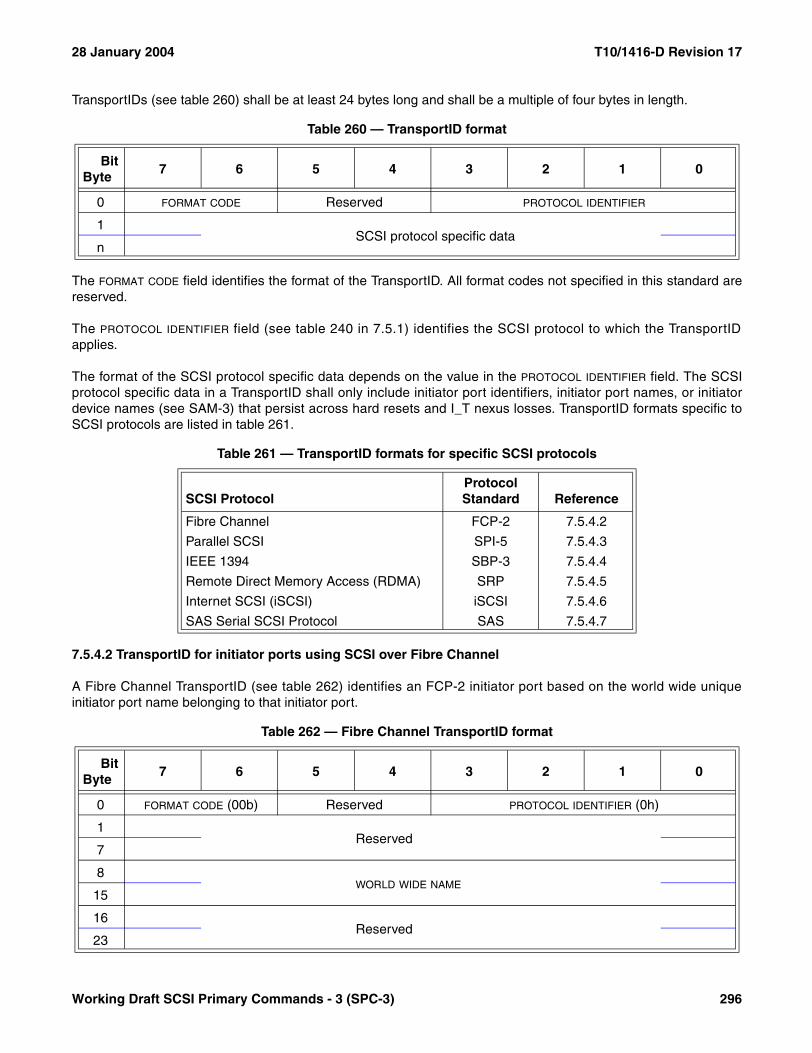
28 January 2004 T10/1416-D Revision 17
TransportIDs (see table 260) shall be at least 24 bytes long and shall be a multiple of four bytes in length.
The FORMAT CODE field identifies the format of the TransportID. All format codes not specified in this standard arereserved.
The PROTOCOL IDENTIFIER field (see table 240 in 7.5.1) identifies the SCSI protocol to which the TransportIDapplies.
The format of the SCSI protocol specific data depends on the value in the PROTOCOL IDENTIFIER field. The SCSIprotocol specific data in a TransportID shall only include initiator port identifiers, initiator port names, or initiatordevice names (see SAM-3) that persist across hard resets and I_T nexus losses. TransportID formats specific toSCSI protocols are listed in table 261.
7.5.4.2 TransportID for initiator ports using SCSI over Fibre Channel
A Fibre Channel TransportID (see table 262) identifies an FCP-2 initiator port based on the world wide uniqueinitiator port name belonging to that initiator port.
Table 260 — TransportID format
BitByte
7 6 5 4 3 2 1 0
0 FORMAT CODE Reserved PROTOCOL IDENTIFIER
1SCSI protocol specific data
n
Table 261 — TransportID formats for specific SCSI protocols
SCSI ProtocolProtocol Standard Reference
Fibre Channel FCP-2 7.5.4.2
Parallel SCSI SPI-5 7.5.4.3
IEEE 1394 SBP-3 7.5.4.4
Remote Direct Memory Access (RDMA) SRP 7.5.4.5
Internet SCSI (iSCSI) iSCSI 7.5.4.6
SAS Serial SCSI Protocol SAS 7.5.4.7
Table 262 — Fibre Channel TransportID format
BitByte
7 6 5 4 3 2 1 0
0 FORMAT CODE (00b) Reserved PROTOCOL IDENTIFIER (0h)
1Reserved
7
8WORLD WIDE NAME
15
16Reserved
23
Working Draft SCSI Primary Commands - 3 (SPC-3) 296

T10/1416-D Revision 17 28 January 2004
The WORLD WIDE NAME field shall contain the port World Wide Name defined by the Physical Log In (PLOGI)extended link service, defined in FC-FS.
7.5.4.3 TransportID for initiator ports using a parallel SCSI bus
A parallel SCSI bus TransportIDs (see table 263) identifies a SPI-5 initiator port based on the SCSI address of aninitiator port and the SCSI target device relative port through which the application client accesses the SCSI targetdevice.
The SCSI ADDRESS field specifies the SCSI address (see SPI-5) of the initiator port.
The RELATIVE PORT IDENTIFIER field specifies the four-byte binary number identifying a specific target port in theSCSI target device relative to other target ports. The relative port identifier value shall be one of the values returnedin the Device Identifier VPD page (see 7.6.4). If the RELATIVE PORT IDENTIFIER does not reference a port in thedevice, the TransportID is invalid.
7.5.4.4 TransportID for initiator ports using SCSI over IEEE 1394
An IEEE 1394 TransportID (see table 264) identifies an SBP-3 initiator port based on the EUI-64 initiator port namebelonging to that initiator port.
The EUI-64 NAME field shall contain the EUI-64 IEEE 1394 node unique identifier (see SBP-3) for an initiator port.
Table 263 — Parallel SCSI bus TransportID format
BitByte
7 6 5 4 3 2 1 0
0 FORMAT CODE (00b) Reserved PROTOCOL IDENTIFIER (1h)
1 Reserved
2 (MSB)SCSI ADDRESS
3 (LSB)
4 (MSB)RELATIVE PORT IDENTIFIER
7 (LSB)
8Reserved
23
Table 264 — IEEE 1394 TransportID format
BitByte
7 6 5 4 3 2 1 0
0 FORMAT CODE (00b) Reserved PROTOCOL IDENTIFIER (3h)
1Reserved
7
8EUI-64 NAME
15
16Reserved
23
297 Working Draft SCSI Primary Commands - 3 (SPC-3)
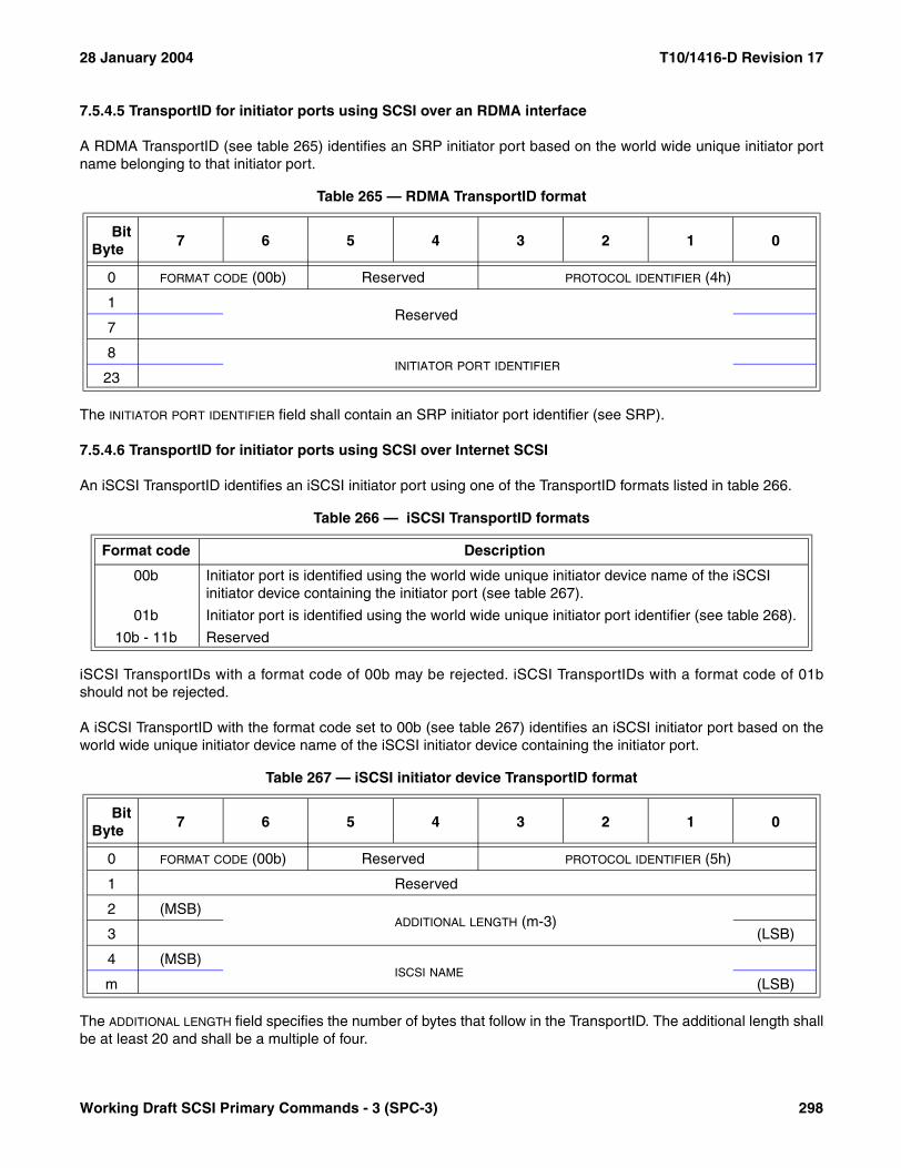
28 January 2004 T10/1416-D Revision 17
7.5.4.5 TransportID for initiator ports using SCSI over an RDMA interface
A RDMA TransportID (see table 265) identifies an SRP initiator port based on the world wide unique initiator portname belonging to that initiator port.
The INITIATOR PORT IDENTIFIER field shall contain an SRP initiator port identifier (see SRP).
7.5.4.6 TransportID for initiator ports using SCSI over Internet SCSI
An iSCSI TransportID identifies an iSCSI initiator port using one of the TransportID formats listed in table 266.
iSCSI TransportIDs with a format code of 00b may be rejected. iSCSI TransportIDs with a format code of 01bshould not be rejected.
A iSCSI TransportID with the format code set to 00b (see table 267) identifies an iSCSI initiator port based on theworld wide unique initiator device name of the iSCSI initiator device containing the initiator port.
The ADDITIONAL LENGTH field specifies the number of bytes that follow in the TransportID. The additional length shallbe at least 20 and shall be a multiple of four.
Table 265 — RDMA TransportID format
BitByte
7 6 5 4 3 2 1 0
0 FORMAT CODE (00b) Reserved PROTOCOL IDENTIFIER (4h)
1Reserved
7
8INITIATOR PORT IDENTIFIER
23
Table 266 — iSCSI TransportID formats
Format code Description
00b Initiator port is identified using the world wide unique initiator device name of the iSCSI initiator device containing the initiator port (see table 267).
01b Initiator port is identified using the world wide unique initiator port identifier (see table 268).
10b - 11b Reserved
Table 267 — iSCSI initiator device TransportID format
BitByte
7 6 5 4 3 2 1 0
0 FORMAT CODE (00b) Reserved PROTOCOL IDENTIFIER (5h)
1 Reserved
2 (MSB)ADDITIONAL LENGTH (m-3)
3 (LSB)
4 (MSB)ISCSI NAME
m (LSB)
Working Draft SCSI Primary Commands - 3 (SPC-3) 298
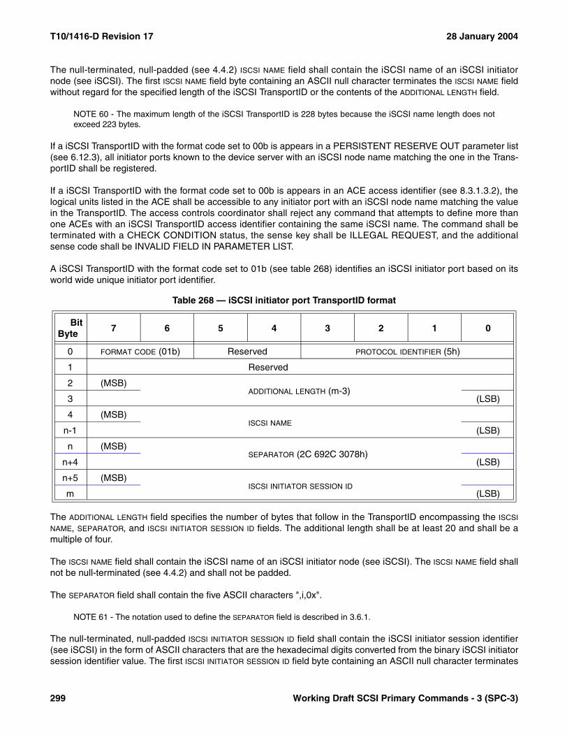
T10/1416-D Revision 17 28 January 2004
The null-terminated, null-padded (see 4.4.2) ISCSI NAME field shall contain the iSCSI name of an iSCSI initiatornode (see iSCSI). The first ISCSI NAME field byte containing an ASCII null character terminates the ISCSI NAME fieldwithout regard for the specified length of the iSCSI TransportID or the contents of the ADDITIONAL LENGTH field.
NOTE 60 - The maximum length of the iSCSI TransportID is 228 bytes because the iSCSI name length does notexceed 223 bytes.
If a iSCSI TransportID with the format code set to 00b is appears in a PERSISTENT RESERVE OUT parameter list(see 6.12.3), all initiator ports known to the device server with an iSCSI node name matching the one in the Trans-portID shall be registered.
If a iSCSI TransportID with the format code set to 00b is appears in an ACE access identifier (see 8.3.1.3.2), thelogical units listed in the ACE shall be accessible to any initiator port with an iSCSI node name matching the valuein the TransportID. The access controls coordinator shall reject any command that attempts to define more thanone ACEs with an iSCSI TransportID access identifier containing the same iSCSI name. The command shall beterminated with a CHECK CONDITION status, the sense key shall be ILLEGAL REQUEST, and the additionalsense code shall be INVALID FIELD IN PARAMETER LIST.
A iSCSI TransportID with the format code set to 01b (see table 268) identifies an iSCSI initiator port based on itsworld wide unique initiator port identifier.
The ADDITIONAL LENGTH field specifies the number of bytes that follow in the TransportID encompassing the ISCSI
NAME, SEPARATOR, and ISCSI INITIATOR SESSION ID fields. The additional length shall be at least 20 and shall be amultiple of four.
The ISCSI NAME field shall contain the iSCSI name of an iSCSI initiator node (see iSCSI). The ISCSI NAME field shallnot be null-terminated (see 4.4.2) and shall not be padded.
The SEPARATOR field shall contain the five ASCII characters ",i,0x".
NOTE 61 - The notation used to define the SEPARATOR field is described in 3.6.1.
The null-terminated, null-padded ISCSI INITIATOR SESSION ID field shall contain the iSCSI initiator session identifier(see iSCSI) in the form of ASCII characters that are the hexadecimal digits converted from the binary iSCSI initiatorsession identifier value. The first ISCSI INITIATOR SESSION ID field byte containing an ASCII null character terminates
Table 268 — iSCSI initiator port TransportID format
BitByte
7 6 5 4 3 2 1 0
0 FORMAT CODE (01b) Reserved PROTOCOL IDENTIFIER (5h)
1 Reserved
2 (MSB)ADDITIONAL LENGTH (m-3)
3 (LSB)
4 (MSB)ISCSI NAME
n-1 (LSB)
n (MSB)SEPARATOR (2C 692C 3078h)
n+4 (LSB)
n+5 (MSB)ISCSI INITIATOR SESSION ID
m (LSB)
299 Working Draft SCSI Primary Commands - 3 (SPC-3)
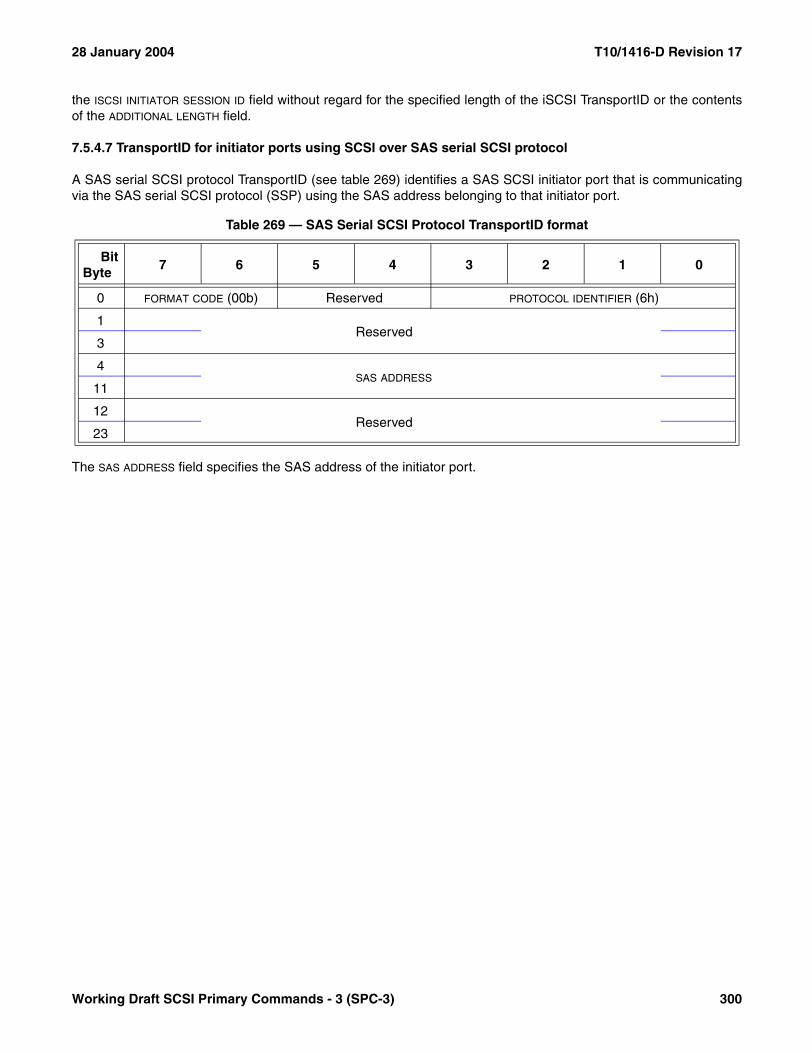
28 January 2004 T10/1416-D Revision 17
the ISCSI INITIATOR SESSION ID field without regard for the specified length of the iSCSI TransportID or the contentsof the ADDITIONAL LENGTH field.
7.5.4.7 TransportID for initiator ports using SCSI over SAS serial SCSI protocol
A SAS serial SCSI protocol TransportID (see table 269) identifies a SAS SCSI initiator port that is communicatingvia the SAS serial SCSI protocol (SSP) using the SAS address belonging to that initiator port.
The SAS ADDRESS field specifies the SAS address of the initiator port.
Table 269 — SAS Serial SCSI Protocol TransportID format
BitByte
7 6 5 4 3 2 1 0
0 FORMAT CODE (00b) Reserved PROTOCOL IDENTIFIER (6h)
1Reserved
3
4SAS ADDRESS
11
12Reserved
23
Working Draft SCSI Primary Commands - 3 (SPC-3) 300

T10/1416-D Revision 17 28 January 2004
7.6 Vital product data parameters
7.6.1 Vital product data parameters overview and page codes
This subclause describes the vital product data (VPD) page structure and the VPD pages (see table 270) that areapplicable to all SCSI devices. These VPD pages are optionally returned by the INQUIRY command (see 6.4) andcontain vendor specific product information about a target or logical unit. The vital product data may include vendoridentification, product identification, unit serial numbers, device operating definitions, manufacturing data, fieldreplaceable unit information, and other vendor specific information. This standard defines the structure of the vitalproduct data, but not the contents.
Table 270 — Vital product data page codes
Page code VPD Page Name ReferenceSupport
Requirements
82h ASCII Implemented Operating Definition 7.6.2 Optional
01h - 7Fh ASCII Information 7.6.3 Optional
83h Device Identification 7.6.4 Mandatory
86h Extended INQUIRY Data 7.6.5 Optional
85h Management Network Addresses 7.6.6 Optional
87h Mode Page Policy 7.6.7 Optional
81h Obsolete 3.3.7
84h Software Interface Identification 7.6.8 Optional
00h Supported VPD Pages 7.6.9 Mandatory
80h Unit Serial Number 7.6.10 Optional
88h - AFh Reserved
B0h - BFh (See specific device type)
C0h - FFh Vendor specific
Annex C contains a listing of VPD page codes in numeric order.
301 Working Draft SCSI Primary Commands - 3 (SPC-3)
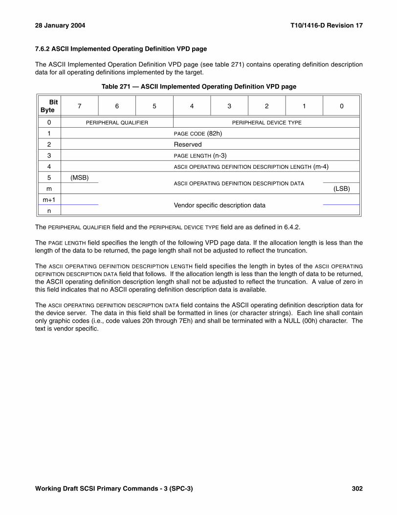
28 January 2004 T10/1416-D Revision 17
7.6.2 ASCII Implemented Operating Definition VPD page
The ASCII Implemented Operation Definition VPD page (see table 271) contains operating definition descriptiondata for all operating definitions implemented by the target.
The PERIPHERAL QUALIFIER field and the PERIPHERAL DEVICE TYPE field are as defined in 6.4.2.
The PAGE LENGTH field specifies the length of the following VPD page data. If the allocation length is less than thelength of the data to be returned, the page length shall not be adjusted to reflect the truncation.
The ASCII OPERATING DEFINITION DESCRIPTION LENGTH field specifies the length in bytes of the ASCII OPERATING
DEFINITION DESCRIPTION DATA field that follows. If the allocation length is less than the length of data to be returned,the ASCII operating definition description length shall not be adjusted to reflect the truncation. A value of zero inthis field indicates that no ASCII operating definition description data is available.
The ASCII OPERATING DEFINITION DESCRIPTION DATA field contains the ASCII operating definition description data forthe device server. The data in this field shall be formatted in lines (or character strings). Each line shall containonly graphic codes (i.e., code values 20h through 7Eh) and shall be terminated with a NULL (00h) character. Thetext is vendor specific.
Table 271 — ASCII Implemented Operating Definition VPD page
BitByte
7 6 5 4 3 2 1 0
0 PERIPHERAL QUALIFIER PERIPHERAL DEVICE TYPE
1 PAGE CODE (82h)
2 Reserved
3 PAGE LENGTH (n-3)
4 ASCII OPERATING DEFINITION DESCRIPTION LENGTH (m-4)
5 (MSB)ASCII OPERATING DEFINITION DESCRIPTION DATA
m (LSB)
m+1Vendor specific description data
n
Working Draft SCSI Primary Commands - 3 (SPC-3) 302

T10/1416-D Revision 17 28 January 2004
7.6.3 ASCII Information VPD page
The ASCII Information VPD page (see table 272) contains information for the field replaceable unit code returnedin the sense data (see 4.5).
The PERIPHERAL QUALIFIER field and the PERIPHERAL DEVICE TYPE field are defined in 6.4.2.
The PAGE CODE field contains the same value as in the PAGE OR OPERATION CODE field of the INQUIRY CDB (see6.4) and is associated with the FIELD REPLACEABLE UNIT CODE field returned in the sense data.
NOTE 62 - The FIELD REPLACEABLE UNIT CODE field in the sense data provides for 255 possible codes, while thePAGE CODE field provides for only 127 possible codes. For that reason it is not possible to return ASCII InformationVPD pages for the upper code values.
The PAGE LENGTH field specifies the length of the following VPD page data. If the allocation length of the CDB is toosmall to transfer all of the VPD page, the page length shall not be adjusted to reflect the truncation.
The ASCII LENGTH field specifies the length in bytes of the ASCII INFORMATION field that follows. If the allocationlength is less than the length of the data to be returned, the ASCII length shall not be adjusted to reflect thetruncation. A value of zero in this field indicates that no ASCII information is available for the specified page code.
The ASCII INFORMATION field contains ASCII information concerning the field replaceable unit identified by the pagecode. The data in this field shall be formatted in one or more character string lines. Each line shall contain onlygraphic codes (i.e., code values 20h through 7Eh) and shall be terminated with a NULL (00h) character.
The contents of the vendor specific information field is not defined in this standard.
7.6.4 Device Identification VPD page
7.6.4.1 Device Identification VPD page overview
The Device Identification VPD page (see table 273) provides the means to retrieve identification descriptorsapplying to the logical unit. Logical units may have more than one identification descriptor (e.g., if several types orassociations of identifier are supported).
Table 272 — ASCII Information VPD page
BitByte
7 6 5 4 3 2 1 0
0 PERIPHERAL QUALIFIER PERIPHERAL DEVICE TYPE
1 PAGE CODE (01h - 7Fh)
2 Reserved
3 PAGE LENGTH (n-3)
4 ASCII LENGTH (m-4)
5 (MSB)ASCII INFORMATION
m (LSB)
m+1Vendor specific information
n
303 Working Draft SCSI Primary Commands - 3 (SPC-3)
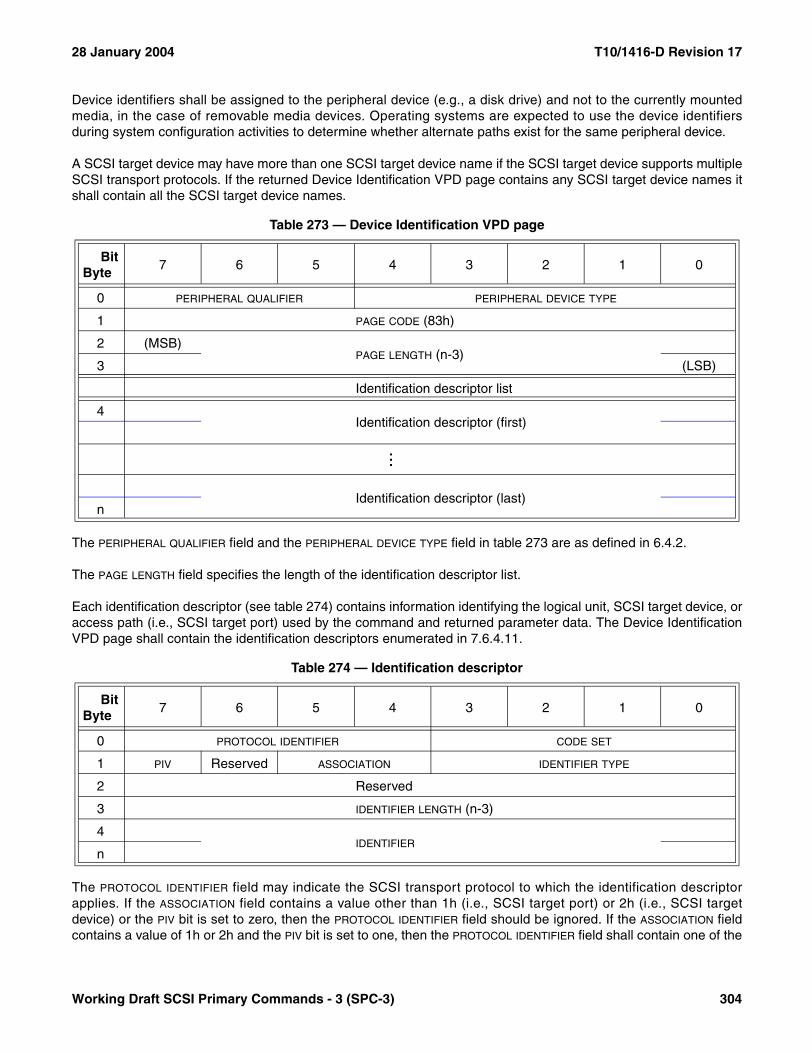
28 January 2004 T10/1416-D Revision 17
Device identifiers shall be assigned to the peripheral device (e.g., a disk drive) and not to the currently mountedmedia, in the case of removable media devices. Operating systems are expected to use the device identifiersduring system configuration activities to determine whether alternate paths exist for the same peripheral device.
A SCSI target device may have more than one SCSI target device name if the SCSI target device supports multipleSCSI transport protocols. If the returned Device Identification VPD page contains any SCSI target device names itshall contain all the SCSI target device names.
The PERIPHERAL QUALIFIER field and the PERIPHERAL DEVICE TYPE field in table 273 are as defined in 6.4.2.
The PAGE LENGTH field specifies the length of the identification descriptor list.
Each identification descriptor (see table 274) contains information identifying the logical unit, SCSI target device, oraccess path (i.e., SCSI target port) used by the command and returned parameter data. The Device IdentificationVPD page shall contain the identification descriptors enumerated in 7.6.4.11.
The PROTOCOL IDENTIFIER field may indicate the SCSI transport protocol to which the identification descriptorapplies. If the ASSOCIATION field contains a value other than 1h (i.e., SCSI target port) or 2h (i.e., SCSI targetdevice) or the PIV bit is set to zero, then the PROTOCOL IDENTIFIER field should be ignored. If the ASSOCIATION fieldcontains a value of 1h or 2h and the PIV bit is set to one, then the PROTOCOL IDENTIFIER field shall contain one of the
Table 273 — Device Identification VPD page
BitByte
7 6 5 4 3 2 1 0
0 PERIPHERAL QUALIFIER PERIPHERAL DEVICE TYPE
1 PAGE CODE (83h)
2 (MSB)PAGE LENGTH (n-3)
3 (LSB)
Identification descriptor list
4Identification descriptor (first)
...
Identification descriptor (last)n
Table 274 — Identification descriptor
BitByte
7 6 5 4 3 2 1 0
0 PROTOCOL IDENTIFIER CODE SET
1 PIV Reserved ASSOCIATION IDENTIFIER TYPE
2 Reserved
3 IDENTIFIER LENGTH (n-3)
4IDENTIFIER
n
Working Draft SCSI Primary Commands - 3 (SPC-3) 304
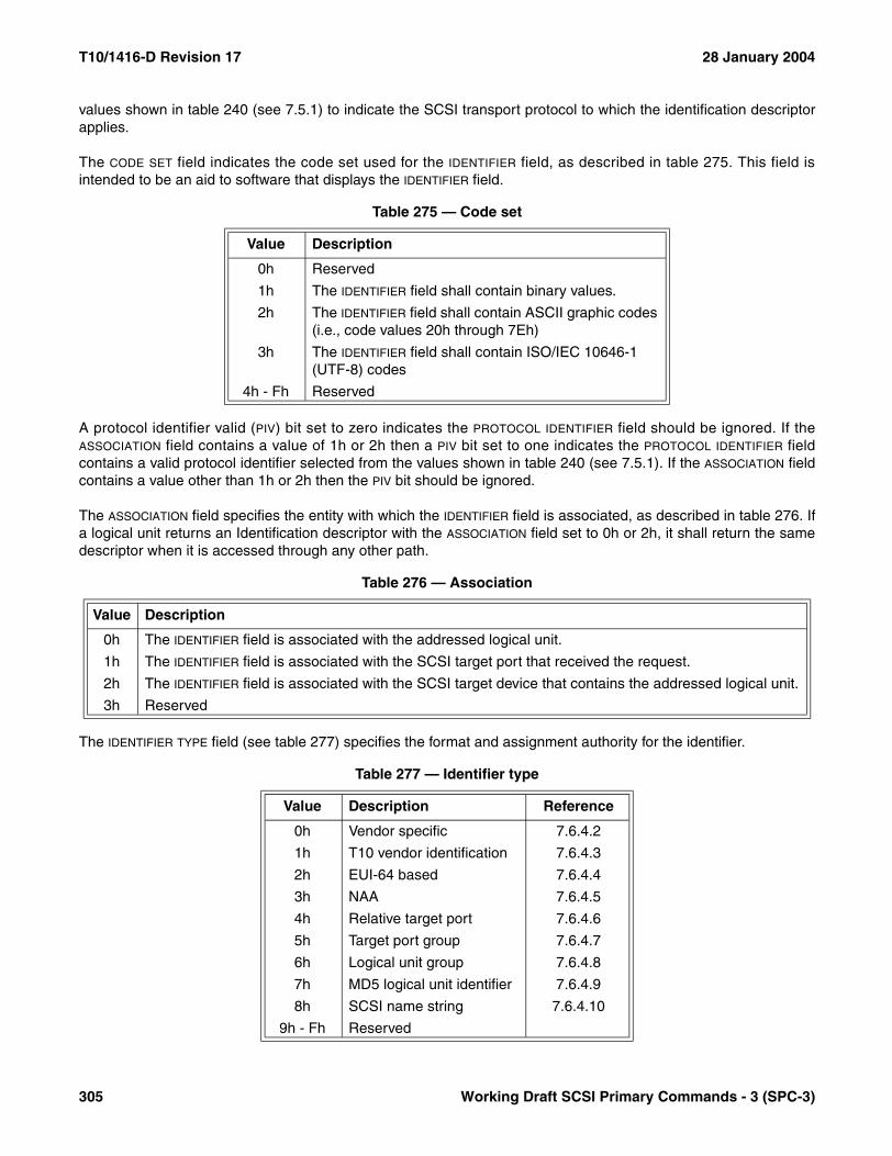
T10/1416-D Revision 17 28 January 2004
values shown in table 240 (see 7.5.1) to indicate the SCSI transport protocol to which the identification descriptorapplies.
The CODE SET field indicates the code set used for the IDENTIFIER field, as described in table 275. This field isintended to be an aid to software that displays the IDENTIFIER field.
A protocol identifier valid (PIV) bit set to zero indicates the PROTOCOL IDENTIFIER field should be ignored. If theASSOCIATION field contains a value of 1h or 2h then a PIV bit set to one indicates the PROTOCOL IDENTIFIER fieldcontains a valid protocol identifier selected from the values shown in table 240 (see 7.5.1). If the ASSOCIATION fieldcontains a value other than 1h or 2h then the PIV bit should be ignored.
The ASSOCIATION field specifies the entity with which the IDENTIFIER field is associated, as described in table 276. Ifa logical unit returns an Identification descriptor with the ASSOCIATION field set to 0h or 2h, it shall return the samedescriptor when it is accessed through any other path.
The IDENTIFIER TYPE field (see table 277) specifies the format and assignment authority for the identifier.
Table 275 — Code set
Value Description
0h Reserved
1h The IDENTIFIER field shall contain binary values.
2h The IDENTIFIER field shall contain ASCII graphic codes (i.e., code values 20h through 7Eh)
3h The IDENTIFIER field shall contain ISO/IEC 10646-1 (UTF-8) codes
4h - Fh Reserved
Table 276 — Association
Value Description
0h The IDENTIFIER field is associated with the addressed logical unit.
1h The IDENTIFIER field is associated with the SCSI target port that received the request.
2h The IDENTIFIER field is associated with the SCSI target device that contains the addressed logical unit.
3h Reserved
Table 277 — Identifier type
Value Description Reference
0h Vendor specific 7.6.4.2
1h T10 vendor identification 7.6.4.3
2h EUI-64 based 7.6.4.4
3h NAA 7.6.4.5
4h Relative target port 7.6.4.6
5h Target port group 7.6.4.7
6h Logical unit group 7.6.4.8
7h MD5 logical unit identifier 7.6.4.9
8h SCSI name string 7.6.4.10
9h - Fh Reserved
305 Working Draft SCSI Primary Commands - 3 (SPC-3)

28 January 2004 T10/1416-D Revision 17
The IDENTIFIER LENGTH field specifies the length in bytes of the IDENTIFIER field. If the ALLOCATION LENGTH field of theCDB is too small to transfer all of the identifier, the identifier length shall not be adjusted to reflect the truncation.
The IDENTIFIER field contains the identifier as described by the ASSOCIATION, IDENTIFIER TYPE, CODE SET, andIDENTIFIER LENGTH fields.
7.6.4.2 Vendor specific identifier format
If the identifier type is 0h (i.e., vendor specific), no assignment authority was used and consequently there is noguarantee that the identifier is globally unique (i.e., the identifier is vendor specific). Table 278 defines theIDENTIFIER field format.
7.6.4.3 T10 vendor identification format
If the identifier type is 1h (i.e., T10 vendor identification), the identifier field has the format shown in table 279.
The VENDOR IDENTIFICATION field contains eight bytes of left-aligned ASCII data (see 4.4.1) identifying the vendor ofthe product. The data shall be left aligned within this field.The vendor identification shall be one assigned byINCITS. A list of assigned vendor identifications is in Annex D and on the T10 web site (www.T10.org).
NOTE 63 - The T10 web site (www.t10.org) provides a convenient means to request an identification code.
The organization associated with the vendor identification is responsible for ensuring that the VENDOR SPECIFIC
IDENTIFIER field is unique in a way that makes the entire IDENTIFIER field unique. A recommended method ofconstructing a unique IDENTIFIER field is to concatenate the PRODUCT IDENTIFICATION field from the standardINQUIRY data (see 6.4.2) and the product serial number field from the Unit Serial Number VPD page (see 7.6.10).
Table 278 — Vendor specific IDENTIFIER field format
BitByte
7 6 5 4 3 2 1 0
0VENDOR SPECIFIC IDENTIFIER
n
Table 279 — T10 vendor IDENTIFIER field format
BitByte
7 6 5 4 3 2 1 0
0 (MSB)VENDOR IDENTIFICATION
7 (LSB)
8VENDOR SPECIFIC IDENTIFIER
n
Working Draft SCSI Primary Commands - 3 (SPC-3) 306

T10/1416-D Revision 17 28 January 2004
7.6.4.4 EUI-64 based identifier format
7.6.4.4.1 EUI-64 based identifier format overview
If the identifier type is 2h (i.e., EUI-64 based identifier), the IDENTIFIER LENGTH field (see table 280) indicates theformat of the identification descriptor.
7.6.4.4.2 EUI-64 identifier format
If the identifier type is 2h (i.e., EUI-64 based identifier) and the IDENTIFIER LENGTH field is set to 0008h, theIDENTIFIER field has the format shown in table 281. The CODE SET field shall be set to 1h (i.e., binary).
The IEEE COMPANY_ID field contains a 24 bit OUI (see 3.1.67) assigned by the IEEE.
The VENDOR SPECIFIC EXTENSION IDENTIFIER field contains a 40 bit numeric value that is uniquely assigned by theorganization associated with the IEEE company_id as required by the IEEE definition of EUI-64 (see E.2).
Table 280 — EUI-64 based identifier lengths
Identifier Length Description Reference
0008h EUI-64 identifier 7.6.4.4.2
000Ch EUI-64 based 12-byte identifier 7.6.4.4.3
0010h EUI-64 based 16-byte identifier 7.6.4.4.4
All other values Reserved
Table 281 — EUI-64 IDENTIFIER field format
BitByte
7 6 5 4 3 2 1 0
0 (MSB)IEEE COMPANY_ID
2 (LSB)
3 (MSB)VENDOR SPECIFIC EXTENSION IDENTIFIER
7 (LSB)
307 Working Draft SCSI Primary Commands - 3 (SPC-3)

28 January 2004 T10/1416-D Revision 17
7.6.4.4.3 EUI-64 based 12-byte identifier format
If the identifier type is 2h (i.e., EUI-64 based identifier) and the IDENTIFIER LENGTH field is set to 000Ch, theIDENTIFIER field has the format shown in table 282. The CODE SET field shall be set to 1h (i.e., binary).
The IEEE COMPANY_ID field and VENDOR SPECIFIC EXTENSION IDENTIFIER field are defined in 7.6.4.4.2.
The DIRECTORY ID field contains a directory identifier, as specified by ISO/IEC 13213:1994.
NOTE 64 - The EUI-64 based 12 byte format may be used to report IEEE 1394 target port identifiers (see SBP-3).
7.6.4.4.4 EUI-64 based 16-byte identifier format
If the identifier type is 2h (i.e., EUI-64 based identifier) and the IDENTIFIER LENGTH field is set to 0010h, theIDENTIFIER field has the format shown in table 283. The CODE SET field shall be set to 1h (i.e., binary).
The IDENTIFIER EXTENSION field contains a 64 bit numeric value.
The IEEE COMPANY_ID field and VENDOR SPECIFIC EXTENSION IDENTIFIER field are defined in 7.6.4.4.2.
NOTE 65 - The EUI-64 based 16-byte format may be used to report SCSI over RDMA target port identifiers (see SRP).
Table 282 — EUI-64 based 12-byte IDENTIFIER field format
BitByte
7 6 5 4 3 2 1 0
0 (MSB)IEEE COMPANY_ID
2 (LSB)
3 (MSB)VENDOR SPECIFIC EXTENSION IDENTIFIER
7 (LSB)
8 (MSB)DIRECTORY ID
11 (LSB)
Table 283 — EUI-64 based 16-byte IDENTIFIER field format
BitByte
7 6 5 4 3 2 1 0
0 (MSB)IDENTIFIER EXTENSION
7 (LSB)
8 (MSB)IEEE COMPANY_ID
10 (LSB)
11 (MSB)VENDOR SPECIFIC EXTENSION IDENTIFIER
15 (LSB)
Working Draft SCSI Primary Commands - 3 (SPC-3) 308
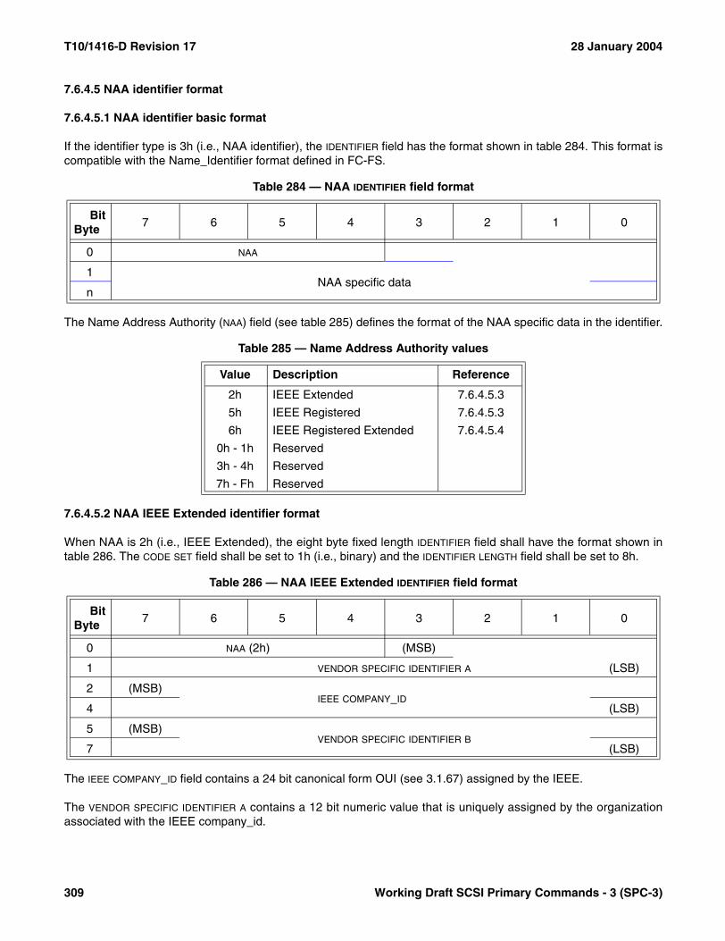
T10/1416-D Revision 17 28 January 2004
7.6.4.5 NAA identifier format
7.6.4.5.1 NAA identifier basic format
If the identifier type is 3h (i.e., NAA identifier), the IDENTIFIER field has the format shown in table 284. This format iscompatible with the Name_Identifier format defined in FC-FS.
The Name Address Authority (NAA) field (see table 285) defines the format of the NAA specific data in the identifier.
7.6.4.5.2 NAA IEEE Extended identifier format
When NAA is 2h (i.e., IEEE Extended), the eight byte fixed length IDENTIFIER field shall have the format shown intable 286. The CODE SET field shall be set to 1h (i.e., binary) and the IDENTIFIER LENGTH field shall be set to 8h.
The IEEE COMPANY_ID field contains a 24 bit canonical form OUI (see 3.1.67) assigned by the IEEE.
The VENDOR SPECIFIC IDENTIFIER A contains a 12 bit numeric value that is uniquely assigned by the organizationassociated with the IEEE company_id.
Table 284 — NAA IDENTIFIER field format
BitByte
7 6 5 4 3 2 1 0
0 NAA
1NAA specific data
n
Table 285 — Name Address Authority values
Value Description Reference
2h IEEE Extended 7.6.4.5.3
5h IEEE Registered 7.6.4.5.3
6h IEEE Registered Extended 7.6.4.5.4
0h - 1h Reserved
3h - 4h Reserved
7h - Fh Reserved
Table 286 — NAA IEEE Extended IDENTIFIER field format
BitByte
7 6 5 4 3 2 1 0
0 NAA (2h) (MSB)
1 VENDOR SPECIFIC IDENTIFIER A (LSB)
2 (MSB)IEEE COMPANY_ID
4 (LSB)
5 (MSB)VENDOR SPECIFIC IDENTIFIER B
7 (LSB)
309 Working Draft SCSI Primary Commands - 3 (SPC-3)
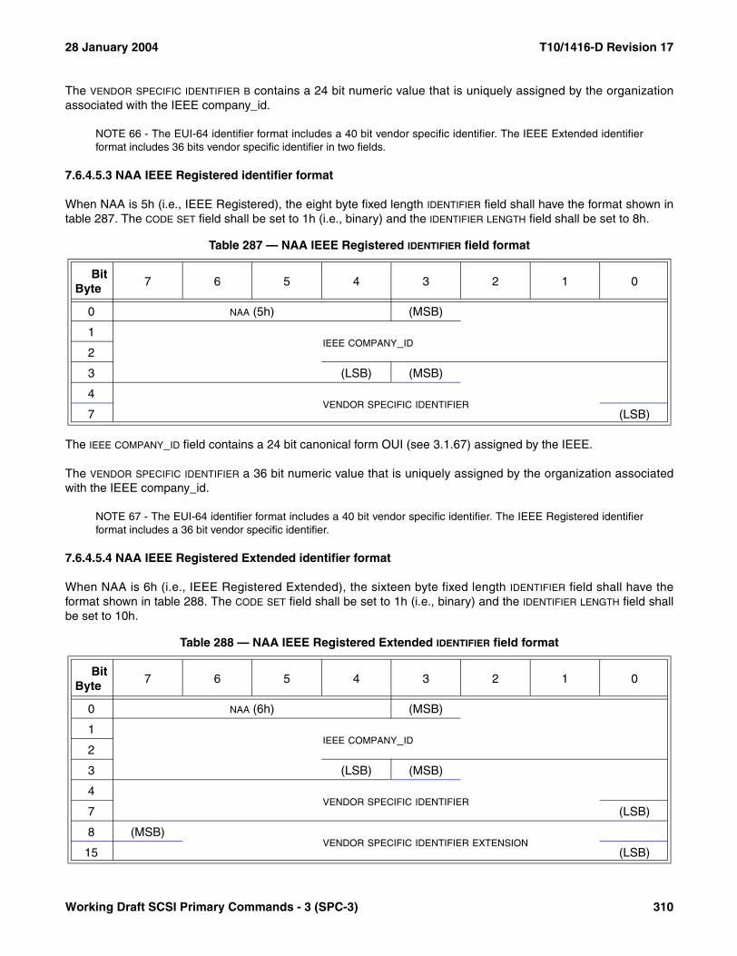
28 January 2004 T10/1416-D Revision 17
The VENDOR SPECIFIC IDENTIFIER B contains a 24 bit numeric value that is uniquely assigned by the organizationassociated with the IEEE company_id.
NOTE 66 - The EUI-64 identifier format includes a 40 bit vendor specific identifier. The IEEE Extended identifierformat includes 36 bits vendor specific identifier in two fields.
7.6.4.5.3 NAA IEEE Registered identifier format
When NAA is 5h (i.e., IEEE Registered), the eight byte fixed length IDENTIFIER field shall have the format shown intable 287. The CODE SET field shall be set to 1h (i.e., binary) and the IDENTIFIER LENGTH field shall be set to 8h.
The IEEE COMPANY_ID field contains a 24 bit canonical form OUI (see 3.1.67) assigned by the IEEE.
The VENDOR SPECIFIC IDENTIFIER a 36 bit numeric value that is uniquely assigned by the organization associatedwith the IEEE company_id.
NOTE 67 - The EUI-64 identifier format includes a 40 bit vendor specific identifier. The IEEE Registered identifierformat includes a 36 bit vendor specific identifier.
7.6.4.5.4 NAA IEEE Registered Extended identifier format
When NAA is 6h (i.e., IEEE Registered Extended), the sixteen byte fixed length IDENTIFIER field shall have theformat shown in table 288. The CODE SET field shall be set to 1h (i.e., binary) and the IDENTIFIER LENGTH field shallbe set to 10h.
Table 287 — NAA IEEE Registered IDENTIFIER field format
BitByte
7 6 5 4 3 2 1 0
0 NAA (5h) (MSB)
1IEEE COMPANY_ID
2
3 (LSB) (MSB)
4VENDOR SPECIFIC IDENTIFIER
7 (LSB)
Table 288 — NAA IEEE Registered Extended IDENTIFIER field format
BitByte
7 6 5 4 3 2 1 0
0 NAA (6h) (MSB)
1IEEE COMPANY_ID
2
3 (LSB) (MSB)
4VENDOR SPECIFIC IDENTIFIER
7 (LSB)
8 (MSB)VENDOR SPECIFIC IDENTIFIER EXTENSION
15 (LSB)
Working Draft SCSI Primary Commands - 3 (SPC-3) 310
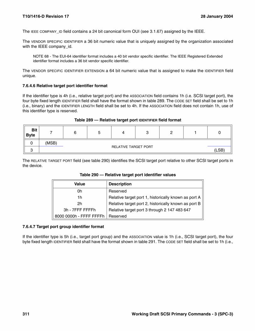
T10/1416-D Revision 17 28 January 2004
The IEEE COMPANY_ID field contains a 24 bit canonical form OUI (see 3.1.67) assigned by the IEEE.
The VENDOR SPECIFIC IDENTIFIER a 36 bit numeric value that is uniquely assigned by the organization associatedwith the IEEE company_id.
NOTE 68 - The EUI-64 identifier format includes a 40 bit vendor specific identifier. The IEEE Registered Extendedidentifier format includes a 36 bit vendor specific identifier.
The VENDOR SPECIFIC IDENTIFIER EXTENSION a 64 bit numeric value that is assigned to make the IDENTIFIER fieldunique.
7.6.4.6 Relative target port identifier format
If the identifier type is 4h (i.e., relative target port) and the ASSOCIATION field contains 1h (i.e. SCSI target port), thefour byte fixed length IDENTIFIER field shall have the format shown in table 289. The CODE SET field shall be set to 1h(i.e., binary) and the IDENTIFIER LENGTH field shall be set to 4h. If the ASSOCIATION field does not contain 1h, use ofthis identifier type is reserved.
The RELATIVE TARGET PORT field (see table 290) identifies the SCSI target port relative to other SCSI target ports inthe device.
7.6.4.7 Target port group identifier format
If the identifier type is 5h (i.e., target port group) and the ASSOCIATION value is 1h (i.e., SCSI target port), the fourbyte fixed length IDENTIFIER field shall have the format shown in table 291. The CODE SET field shall be set to 1h (i.e.,
Table 289 — Relative target port IDENTIFIER field format
BitByte
7 6 5 4 3 2 1 0
0 (MSB)RELATIVE TARGET PORT
3 (LSB)
Table 290 — Relative target port identifier values
Value Description
0h Reserved
1h Relative target port 1, historically known as port A
2h Relative target port 2, historically known as port B
3h - 7FFF FFFFh Relative target port 3 through 2 147 483 647
8000 0000h - FFFF FFFFh Reserved
311 Working Draft SCSI Primary Commands - 3 (SPC-3)
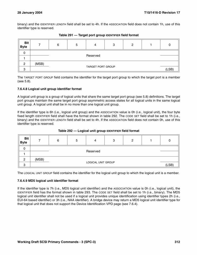
28 January 2004 T10/1416-D Revision 17
binary) and the IDENTIFIER LENGTH field shall be set to 4h. If the ASSOCIATION field does not contain 1h, use of thisidentifier type is reserved.
The TARGET PORT GROUP field contains the identifier for the target port group to which the target port is a member(see 5.8).
7.6.4.8 Logical unit group identifier format
A logical unit group is a group of logical units that share the same target port group (see 5.8) definitions. The targetport groups maintain the same target port group asymmetric access states for all logical units in the same logicalunit group. A logical unit shall be in no more than one logical unit group.
If the identifier type is 6h (i.e., logical unit group) and the ASSOCIATION value is 0h (i.e., logical unit), the four bytefixed length IDENTIFIER field shall have the format shown in table 292. The CODE SET field shall be set to 1h (i.e.,binary) and the IDENTIFIER LENGTH field shall be set to 4h. If the ASSOCIATION field does not contain 0h, use of thisidentifier type is reserved.
The LOGICAL UNIT GROUP field contains the identifier for the logical unit group to which the logical unit is a member.
7.6.4.9 MD5 logical unit identifier format
If the identifier type is 7h (i.e., MD5 logical unit identifier) and the ASSOCIATION value is 0h (i.e., logical unit), theIDENTIFIER field has the format shown in table 293. The CODE SET field shall be set to 1h (i.e., binary). The MD5logical unit identifier shall not be used if a logical unit provides unique identification using identifier types 2h (i.e.,EUI-64 based identifier) or 3h (i.e., NAA identifier). A bridge device may return a MD5 logical unit identifier type forthat logical unit that does not support the Device Identification VPD page (see 7.6.4).
Table 291 — Target port group IDENTIFIER field format
BitByte
7 6 5 4 3 2 1 0
0Reserved
1
2 (MSB)TARGET PORT GROUP
3 (LSB)
Table 292 — Logical unit group IDENTIFIER field format
BitByte
7 6 5 4 3 2 1 0
0Reserved
1
2 (MSB)LOGICAL UNIT GROUP
3 (LSB)
Working Draft SCSI Primary Commands - 3 (SPC-3) 312

T10/1416-D Revision 17 28 January 2004
If the ASSOCIATION field does not contain 0h, use of this identifier type is reserved.
The MD5 LOGICAL UNIT IDENTIFIER field contains the message digest of the supplied message input. The messagedigest shall be generated using the MD5 message-digest algorithm as specified in RFC 1321 (see 2.4) with thefollowing information as message input:
1) The contents of the VENDOR IDENTIFICATION field in the standard INQUIRY data (see 6.4.2);2) The contents of the PRODUCT IDENTIFICATION field in the standard INQUIRY data;3) The contents of the PRODUCT SERIAL NUMBER field in the Unit Serial Number VPD page (see 7.6.10);4) The contents of a vendor specific IDENTIFIER field (type 0h) from the Device Identification VPD page; and5) The contents of a T10 vendor identification IDENTIFIER field (type 1h) from the Device Identification VPD
page.
If a field or page is not available, the message input for that field or page shall be 8 bytes of ASCII space characters(i.e., 20h).
The uniqueness of the MD5 logical unit identifier is dependent upon the relative degree of randomness (i.e., theentropy) of the message input. If it is found that two or more logical units have the same MD5 logical unit identifier,the application client should determine in a vendor specific manner whether the logical units are the same entities.
The MD5 logical unit identifier example described in this paragraph and shown in table 294 and table 295 is not anormative part of this standard. The data available for input to the MD5 algorithm for this example is shown in table294.
The concatenation of the fields in table 294 to form input to the MD5 algorithm is shown in table 295.
Table 293 — MD5 logical unit IDENTIFIER field format
BitByte
7 6 5 4 3 2 1 0
0 (MSB)MD5 LOGICAL UNIT IDENTIFIER
15 (LSB)
Table 294 — MD5 logical unit identifier example available data
MD5 message input Available Contents
VENDOR IDENTIFICATION field Yes T10
PRODUCT IDENTIFICATION field Yes MD5 Logical Unit
PRODUCT SERIAL NUMBER field Yes 00100203 04050607h
vendor specific IDENTIFIER field No
T10 vendor identification IDENTIFIER field No
Table 295 — Example MD5 input for computation of a logical unit identifier
Bytes Hexadecimal values ASCII values
00 – 15 54 31 30 20 20 20 20 20 4D 44 35 20 4C 6F 67 69 T10 MD5 Logi
16 – 31 63 61 6C 20 55 6E 69 74 00 01 02 03 04 05 06 07 cal Unit........
32 – 47 20 20 20 20 20 20 20 20 20 20 20 20 20 20 20 20
NOTE 1 Non-printing ASCII characters are shown as '.'.
313 Working Draft SCSI Primary Commands - 3 (SPC-3)
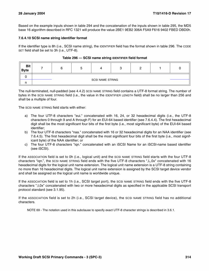
28 January 2004 T10/1416-D Revision 17
Based on the example inputs shown in table 294 and the concatenation of the inputs shown in table 295, the MD5base 16 algorithm described in RFC 1321 will produce the value 2BE1 9EB2 306A F5A9 F616 9402 FBED DBD0h.
7.6.4.10 SCSI name string identifier format
If the identifier type is 8h (i.e., SCSI name string), the IDENTIFIER field has the format shown in table 296. The CODE
SET field shall be set to 3h (i.e., UTF-8).
The null-terminated, null-padded (see 4.4.2) SCSI NAME STRING field contains a UTF-8 format string. The number ofbytes in the SCSI NAME STRING field (i.e., the value in the IDENTIFIER LENGTH field) shall be no larger than 256 andshall be a multiple of four.
The SCSI NAME STRING field starts with either:
a) The four UTF-8 characters "eui." concatenated with 16, 24, or 32 hexadecimal digits (i.e., the UTF-8characters 0 through 9 and A through F) for an EUI-64 based identifier (see 7.6.4.4). The first hexadecimaldigit shall be the most significant four bits of the first byte (i.e., most significant byte) of the EUI-64 basedidentifier;
b) The four UTF-8 characters "naa." concatenated with 16 or 32 hexadecimal digits for an NAA identifier (see7.6.4.5). The first hexadecimal digit shall be the most significant four bits of the first byte (i.e., most signif-icant byte) of the NAA identifier; or
c) The four UTF-8 characters "iqn." concatenated with an iSCSI Name for an iSCSI-name based identifier(see iSCSI).
If the ASSOCIATION field is set to 0h (i.e., logical unit) and the SCSI NAME STRING field starts with the four UTF-8characters “iqn.”, the SCSI NAME STRING field ends with the five UTF-8 characters ",L,0x" concatenated with 16hexadecimal digits for the logical unit name extension. The logical unit name extension is a UTF-8 string containingno more than 16 hexadecimal digits. The logical unit name extension is assigned by the SCSI target device vendorand shall be assigned so the logical unit name is worldwide unique.
If the ASSOCIATION field is set to 1h (i.e., SCSI target port), the SCSI NAME STRING field ends with the five UTF-8characters ",t,0x" concatenated with two or more hexadecimal digits as specified in the applicable SCSI transportprotocol standard (see 3.1.95).
If the ASSOCIATION field is set to 2h (i.e., SCSI target device), the SCSI NAME STRING field has no additionalcharacters.
NOTE 69 - The notation used in this subclause to specify exact UTF-8 character strings is described in 3.6.1.
Table 296 — SCSI name string IDENTIFIER field format
BitByte
7 6 5 4 3 2 1 0
0SCSI NAME STRING
n
Working Draft SCSI Primary Commands - 3 (SPC-3) 314
T10/1416-D Revision 17 28 January 2004
7.6.4.11 Device identification descriptor requirements
7.6.4.11.1 Identification descriptors for SCSI target devices
The Device Identification VPD page shall have one or more identification descriptors for the SCSI target device.Each SCSI target device identification descriptor shall have the ASSOCIATION field set to 2h (i.e., SCSI target device)and the IDENTIFIER TYPE field set to:
a) 2h (i.e., EUI-64-based);b) 3h (i.e., NAA); orc) 8h (i.e., SCSI name string).
The Device Identification VPD page shall contain identification descriptors for all the SCSI target device names forall the SCSI transport protocols supported by the SCSI target device.
7.6.4.11.2 Identification descriptors for SCSI target ports
For the SCSI target port through which the Device Identification VPD page is accessed, the Device IdentificationVPD page should include one identification descriptor with the ASSOCIATION field set to 1h (i.e., SCSI target port)and the IDENTIFIER TYPE field set to 4h (i.e., relative target port) identifying the SCSI target port being used toretrieve the identification descriptors.
A SCSI target port name identification descriptor shall have the ASSOCIATION field set to 1h (i.e., SCSI target port)and the IDENTIFIER TYPE field set to:
a) 2h (i.e., EUI-64-based);b) 3h (i.e., NAA); orc) 8h (i.e., SCSI name string).
If the SCSI transport protocol standard (see 3.1.95) for the SCSI target port defines target port names, an identifi-cation descriptor shall contain the SCSI target port name. If the SCSI transport protocol for the SCSI target portdoes not define SCSI target port names, an identification descriptor shall contain the SCSI target port identifier.
7.6.4.11.3 Identification descriptors for logical units
For each logical unit that is not a well known logical unit, the Device Identification VPD page shall include at leastone identification descriptor. The identification descriptor shall have the ASSOCIATION field set to 0h (i.e., logical unit)and the IDENTIFIER TYPE field set to:
a) 1h (i.e., T10 vendor identification);b) 2h (i.e., EUI-64-based); c) 3h (i.e., NAA); ord) 8h (i.e., SCSI name string).
At least one identification descriptor should have the IDENTIFIER TYPE field set to:
a) 2h (i.e., EUI-64-based);b) 3h (i.e., NAA); orc) 8h (i.e., SCSI name string).
In the case of virtual logical units (e.g., volume sets as defined by SCC-2), identification descriptors should containan IDENTIFIER TYPE field set to:
a) 2h (i.e., EUI-64-based);
315 Working Draft SCSI Primary Commands - 3 (SPC-3)
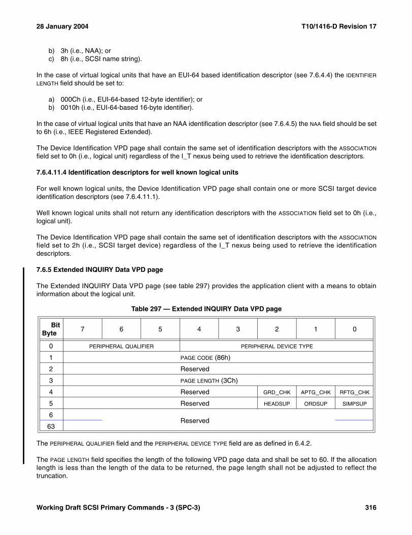
28 January 2004 T10/1416-D Revision 17
b) 3h (i.e., NAA); orc) 8h (i.e., SCSI name string).
In the case of virtual logical units that have an EUI-64 based identification descriptor (see 7.6.4.4) the IDENTIFIER
LENGTH field should be set to:
a) 000Ch (i.e., EUI-64-based 12-byte identifier); orb) 0010h (i.e., EUI-64-based 16-byte identifier).
In the case of virtual logical units that have an NAA identification descriptor (see 7.6.4.5) the NAA field should be setto 6h (i.e., IEEE Registered Extended).
The Device Identification VPD page shall contain the same set of identification descriptors with the ASSOCIATION
field set to 0h (i.e., logical unit) regardless of the I_T nexus being used to retrieve the identification descriptors.
7.6.4.11.4 Identification descriptors for well known logical units
For well known logical units, the Device Identification VPD page shall contain one or more SCSI target deviceidentification descriptors (see 7.6.4.11.1).
Well known logical units shall not return any identification descriptors with the ASSOCIATION field set to 0h (i.e.,logical unit).
The Device Identification VPD page shall contain the same set of identification descriptors with the ASSOCIATION
field set to 2h (i.e., SCSI target device) regardless of the I_T nexus being used to retrieve the identificationdescriptors.
7.6.5 Extended INQUIRY Data VPD page
The Extended INQUIRY Data VPD page (see table 297) provides the application client with a means to obtaininformation about the logical unit.
The PERIPHERAL QUALIFIER field and the PERIPHERAL DEVICE TYPE field are as defined in 6.4.2.
The PAGE LENGTH field specifies the length of the following VPD page data and shall be set to 60. If the allocationlength is less than the length of the data to be returned, the page length shall not be adjusted to reflect thetruncation.
Table 297 — Extended INQUIRY Data VPD page
BitByte
7 6 5 4 3 2 1 0
0 PERIPHERAL QUALIFIER PERIPHERAL DEVICE TYPE
1 PAGE CODE (86h)
2 Reserved
3 PAGE LENGTH (3Ch)
4 Reserved GRD_CHK APTG_CHK RFTG_CHK
5 Reserved HEADSUP ORDSUP SIMPSUP
6Reserved
63
Working Draft SCSI Primary Commands - 3 (SPC-3) 316

T10/1416-D Revision 17 28 January 2004
A guard check (GRD_CHK) bit set to zero indicates the device server does not check the LOGICAL BLOCK GUARD fieldin the protection information (see SBC-2) before transmitting it to an application client. A GRD_CHK bit set to oneindicates the device server checks the LOGICAL BLOCK GUARD field in the protection information before transmitting itto an application client. If the application client or device server detects a LOGICAL BLOCK APPLICATION TAG fieldcontaining FFFFh, the checking of the LOGICAL BLOCK GUARD field in the protection information shall not beperformed for the associated logical block.
An application tag check (APTG_CHK) bit set to zero indicates the device server does not check the LOGICAL BLOCK
APPLICATION TAG field in the protection information (see SBC-2) before transmitting it to an application client. AnAPTG_CHK bit set to one indicates the device server checks the LOGICAL BLOCK APPLICATION TAG field in theprotection information before transmitting it to an application client. If the application client or device server detectsa LOGICAL BLOCK APPLICATION TAG field containing FFFFh, the checking of the LOGICAL BLOCK APPLICATION TAG fieldin the protection information shall not be performed for the associated logical block.
A reference tag check (RFTG_CHK) bit set to zero indicates the device server does not check the LOGICAL BLOCK
REFERENCE TAG field in the protection information (see SBC-2) before transmitting it to an application client. ARFTG_CHK bit set to one indicates the device server checks the LOGICAL BLOCK REFERENCE TAG field in theprotection information before transmitting it to an application client. If the application client or device server detectsa LOGICAL BLOCK APPLICATION TAG field containing FFFFh, the checking of the LOGICAL BLOCK REFERENCE TAG fieldin the protection information shall not be performed for the associated logical block.
A head of queue supported (HEADSUP) bit set to one shall indicate that the HEAD OF QUEUE task attribute (seeSAM-3) is supported by the logical unit. A HEADSUP bit set to zero shall indicate that the HEAD OF QUEUE taskattribute is not supported. If the HEADSUP bit is set to zero application clients should not specify the HEAD OF QUEUE
task attribute as an Execute Command (see 4.2) procedure call argument.
An ordered supported (ORDSUP) bit set to one shall indicate that the ORDERED task attribute (see SAM-3) issupported by the logical unit. An ORDSUP bit set to zero shall indicate that the ORDERED task attribute is notsupported. If the ORDSUP bit is set to zero application clients should not specify the ORDERED task attribute as anExecute Command procedure call argument.
A simple supported (SIMPSUP) bit set to one shall indicate that the SIMPLE task attribute (see SAM-3) is supportedby the logical unit. Logical units that support the full task management model (see SAM-3) shall set the SIMPSUP bitto one. A SIMPSUP bit set to zero shall indicate that the SIMPLE task attribute is not supported. If the SIMPSUP bit is setto zero application clients should not specify the SIMPLE task attribute as an Execute Command procedure callargument.
SAM-3 defines how unsupported task attributes are processed.
317 Working Draft SCSI Primary Commands - 3 (SPC-3)

28 January 2004 T10/1416-D Revision 17
7.6.6 Management Network Addresses VPD page
The Management Network Addresses VPD page (see table 298) provides a list of network addresses ofmanagement services associated with a SCSI target device, SCSI target port, or logical unit.
The PERIPHERAL QUALIFIER field and the PERIPHERAL DEVICE TYPE field are as defined in 6.4.2.
The PAGE LENGTH field specifies the length of the network services descriptor list.
Each network service descriptor (see table 299) contains information about one management service.
The ASSOCIATION field (see table 276 in 7.6.4.1) specifies the entity (i.e., SCSI target device, SCSI target port, orlogical unit) with which the service is associated.
Table 298 — Management Network Addresses VPD page
BitByte
7 6 5 4 3 2 1 0
0 PERIPHERAL QUALIFIER PERIPHERAL DEVICE TYPE
1 PAGE CODE (85h)
2 (MSB)PAGE LENGTH (n-3)
3 (LSB)
Network services descriptor list
4Network services descriptor (first)
...
Network services descriptor (last)n
Table 299 — Network service descriptor format
BitByte
7 6 5 4 3 2 1 0
0 Reserved ASSOCIATION SERVICE TYPE
1 Reserved
2 (MSB)NETWORK ADDRESS LENGTH (n-3)
3 (LSB)
4NETWORK ADDRESS
n
Working Draft SCSI Primary Commands - 3 (SPC-3) 318

T10/1416-D Revision 17 28 January 2004
The SERVICE TYPE field (see table 300) allows differentiation of multiple services with the same protocol running atdifferent port numbers or paths.
NOTE 70 - A SCSI target device may provide separate HTTP services for configuration and diagnostics. One ofthese services may use the standard HTTP port 80 (see E.5) and the other service may use a different port (e.g.,8080).
The NETWORK ADDRESS LENGTH field contains the length in bytes of the NETWORK ADDRESS field. The networkaddress length shall be a multiple of four.
The null-terminated, null-padded NETWORK ADDRESS field contains the URL form of a URI as defined in RFC 2396.
7.6.7 Mode Page Policy VPD page
The Mode Page Policy VPD page (see table 301) indicates which mode page policy (see 6.7) is in effect for eachmode page supported by the logical unit.
The PERIPHERAL QUALIFIER field and the PERIPHERAL DEVICE TYPE field are as defined in 6.4.2.
The PAGE LENGTH field specifies the length of the mode page policy descriptor list.
Table 300 — Network services type
Type Description
00h Unspecified
01h Storage Configuration Service
02h Diagnostics
03h Status
04h Logging
05h Code Download
06h - 1Fh Reserved
Table 301 — Mode Page Policy VPD page
BitByte
7 6 5 4 3 2 1 0
0 PERIPHERAL QUALIFIER PERIPHERAL DEVICE TYPE
1 PAGE CODE (87h)
2 (MSB)PAGE LENGTH (n-3)
3 (LSB)
Mode page policy descriptor list
4Mode page policy descriptor (first)
7...
n-3Mode page policy descriptor (last)
n
319 Working Draft SCSI Primary Commands - 3 (SPC-3)

28 January 2004 T10/1416-D Revision 17
Each mode page policy descriptor (see table 302) contains information describing the mode page policy for one ormore mode pages or subpages (see 7.4.5). The information in the mode page policy descriptors in this VPD pageshall describe the mode page policy for every mode page and subpage supported by the logical unit.
The POLICY PAGE CODE field and POLICY SUBPAGE CODE field indicate the mode page and subpage to which thedescriptor applies.
If the first mode page policy descriptor in the list contains a POLICY PAGE CODE field set to 3Fh and a POLICY
SUBPAGE CODE field set to FFh, then the descriptor applies to all mode pages and subpages not described by othermode page policy descriptors. The POLICY PAGE CODE field shall be set to 3Fh and the POLICY SUBPAGE CODE fieldshall be set to FFh only in the first mode page policy descriptor in the list.
If the POLICY PAGE CODE field contains a value other than 3Fh or a POLICY SUBPAGE CODE field contains a value otherthan FFh, then the POLICY PAGE CODE field and the POLICY SUBPAGE CODE field indicate a single mode page andsubpage to which the descriptor applies.
If the POLICY PAGE CODE field contains a value other than 3Fh, then POLICY SUBPAGE CODE field shall contain a valueother than FFh. If the POLICY SUBPAGE CODE field contains a value other than FFh, then POLICY PAGE CODE field shallcontain a value other than 3Fh.
A multiple logical units share (MLUS) bit set to one indicates the mode page and subpage identified by the POLICY
PAGE CODE field and POLICY SUBPAGE CODE field is shared by more than one logical unit. A MLUS bit set to zeroindicates the logical unit maintains its own copy of the mode page and subpage identified by the POLICY PAGE CODE
field and POLICY SUBPAGE CODE field.
The MLUS bit should be set to one in the mode page policy descriptors or descriptor that indicates the mode pagepolicy for the:
a) Disconnect-Reconnect mode page (see 7.4.8); andb) Protocol Specific Logical Unit mode page (see 7.4.13).
The MODE PAGE POLICY field (see table 303) indicates the mode page policy for the mode page and subpageidentified by the POLICY PAGE CODE field and POLICY SUBPAGE CODE field. The mode page policies are described intable 90 (see 6.7).
Table 302 — Mode page policy descriptor
BitByte
7 6 5 4 3 2 1 0
0 Reserved POLICY PAGE CODE
1 POLICY SUBPAGE CODE
2 MLUS Reserved MODE PAGE POLICY
3 Reserved
Table 303 — Mode page policy values
Value Description
00b Shared
01b Per target port
10b Per initiator port
11b Per I_T nexus
Working Draft SCSI Primary Commands - 3 (SPC-3) 320

T10/1416-D Revision 17 28 January 2004
7.6.8 Software Interface Identification page
The Software Interface Identification VPD page (see table 304) provides identification of software interfaces appli-cable to the logical unit. Logical units may have more than one associated software interface identifier.
NOTE 71 - Application clients may use the software IDs to differentiate peripheral device function in cases wherethe command set (e.g., processor devices) is too generic to distinguish different software interfaces implemented.
The PERIPHERAL QUALIFIER field and the PERIPHERAL DEVICE TYPE field are defined in 6.4.2.
The PAGE LENGTH field specifies the length of the software interface identifier list. If the allocation length is too smallto transfer all of the VPD page, the page length shall not be adjusted to reflect the truncation.
Each software interface identifier (see table 305) is a six-byte, fixed-length field that contains information identifyinga software interface implemented by the logical unit. The contents of software interface identifier are in EUI-48format (see E.2).
The OUI field contains a 24 bit OUI (see 3.1.67) assigned by the IEEE.
The VENDOR SPECIFIC EXTENSION IDENTIFIER a 24 bit numeric value that is uniquely assigned by the organizationassociated with the OUI as required by the IEEE definition of EUI-48 (see E.1). The combination of OUI and vendorspecific extension identifier shall uniquely identify the document or documents that specify the supported softwareinterface.
Table 304 — Software Interface Identification VPD page
BitByte
7 6 5 4 3 2 1 0
0 PERIPHERAL QUALIFIER PERIPHERAL DEVICE TYPE
1 PAGE CODE (84h)
2 Reserved
3 PAGE LENGTH (n-3)
Software interface identifier list
4Software interface identifier (first)
...
Software interface identifier (last)n
Table 305 — Software interface identifier format
BitByte
7 6 5 4 3 2 1 0
0 (MSB)OUI
2 (LSB)
3 (MSB)VENDOR SPECIFIC EXTENSION IDENTIFIER
5 (LSB)
321 Working Draft SCSI Primary Commands - 3 (SPC-3)
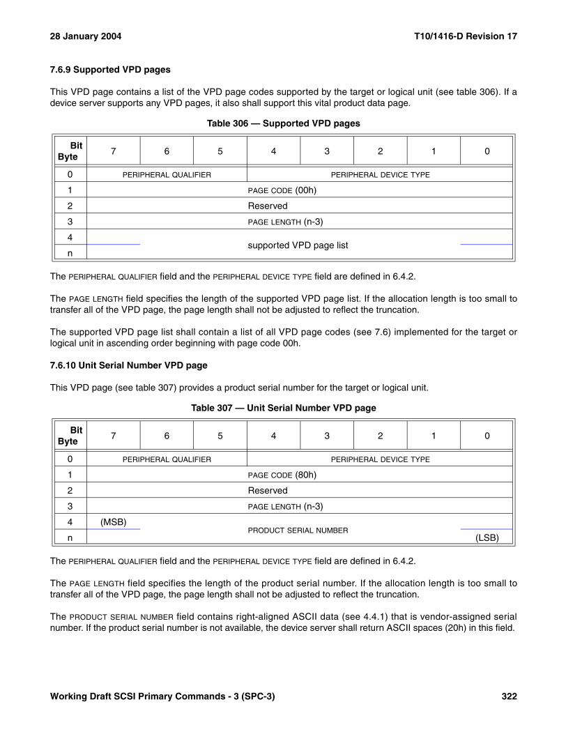
28 January 2004 T10/1416-D Revision 17
7.6.9 Supported VPD pages
This VPD page contains a list of the VPD page codes supported by the target or logical unit (see table 306). If adevice server supports any VPD pages, it also shall support this vital product data page.
The PERIPHERAL QUALIFIER field and the PERIPHERAL DEVICE TYPE field are defined in 6.4.2.
The PAGE LENGTH field specifies the length of the supported VPD page list. If the allocation length is too small totransfer all of the VPD page, the page length shall not be adjusted to reflect the truncation.
The supported VPD page list shall contain a list of all VPD page codes (see 7.6) implemented for the target orlogical unit in ascending order beginning with page code 00h.
7.6.10 Unit Serial Number VPD page
This VPD page (see table 307) provides a product serial number for the target or logical unit.
The PERIPHERAL QUALIFIER field and the PERIPHERAL DEVICE TYPE field are defined in 6.4.2.
The PAGE LENGTH field specifies the length of the product serial number. If the allocation length is too small totransfer all of the VPD page, the page length shall not be adjusted to reflect the truncation.
The PRODUCT SERIAL NUMBER field contains right-aligned ASCII data (see 4.4.1) that is vendor-assigned serialnumber. If the product serial number is not available, the device server shall return ASCII spaces (20h) in this field.
Table 306 — Supported VPD pages
BitByte
7 6 5 4 3 2 1 0
0 PERIPHERAL QUALIFIER PERIPHERAL DEVICE TYPE
1 PAGE CODE (00h)
2 Reserved
3 PAGE LENGTH (n-3)
4supported VPD page list
n
Table 307 — Unit Serial Number VPD page
BitByte
7 6 5 4 3 2 1 0
0 PERIPHERAL QUALIFIER PERIPHERAL DEVICE TYPE
1 PAGE CODE (80h)
2 Reserved
3 PAGE LENGTH (n-3)
4 (MSB)PRODUCT SERIAL NUMBER
n (LSB)
Working Draft SCSI Primary Commands - 3 (SPC-3) 322
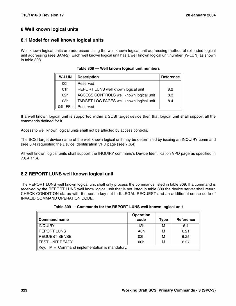
T10/1416-D Revision 17 28 January 2004
8 Well known logical units
8.1 Model for well known logical units
Well known logical units are addressed using the well known logical unit addressing method of extended logicalunit addressing (see SAM-2). Each well known logical unit has a well known logical unit number (W-LUN) as shownin table 308.
If a well known logical unit is supported within a SCSI target device then that logical unit shall support all thecommands defined for it.
Access to well known logical units shall not be affected by access controls.
The SCSI target device name of the well known logical unit may be determined by issuing an INQUIRY command(see 6.4) requesting the Device Identification VPD page (see 7.6.4).
All well known logical units shall support the INQUIRY command’s Device Identification VPD page as specified in7.6.4.11.4.
8.2 REPORT LUNS well known logical unit
The REPORT LUNS well known logical unit shall only process the commands listed in table 309. If a command isreceived by the REPORT LUNS well know logical unit that is not listed in table 309 the device server shall returnCHECK CONDITION status with the sense key set to ILLEGAL REQUEST and an additional sense code ofINVALID COMMAND OPERATION CODE.
Table 308 — Well known logical unit numbers
W-LUN Description Reference
00h Reserved
01h REPORT LUNS well known logical unit 8.2
02h ACCESS CONTROLS well known logical unit 8.3
03h TARGET LOG PAGES well known logical unit 8.4
04h-FFh Reserved
Table 309 — Commands for the REPORT LUNS well known logical unit
Command nameOperation
code Type Reference
INQUIRY 12h M 6.4REPORT LUNS A0h M 6.21REQUEST SENSE 03h M 6.25TEST UNIT READY 00h M 6.27Key: M = Command implementation is mandatory.
323 Working Draft SCSI Primary Commands - 3 (SPC-3)
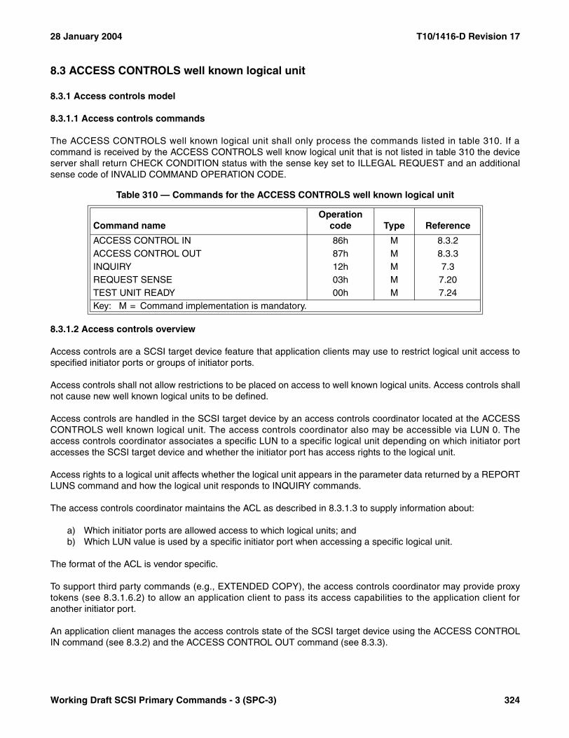
28 January 2004 T10/1416-D Revision 17
8.3 ACCESS CONTROLS well known logical unit
8.3.1 Access controls model
8.3.1.1 Access controls commands
The ACCESS CONTROLS well known logical unit shall only process the commands listed in table 310. If acommand is received by the ACCESS CONTROLS well know logical unit that is not listed in table 310 the deviceserver shall return CHECK CONDITION status with the sense key set to ILLEGAL REQUEST and an additionalsense code of INVALID COMMAND OPERATION CODE.
8.3.1.2 Access controls overview
Access controls are a SCSI target device feature that application clients may use to restrict logical unit access tospecified initiator ports or groups of initiator ports.
Access controls shall not allow restrictions to be placed on access to well known logical units. Access controls shallnot cause new well known logical units to be defined.
Access controls are handled in the SCSI target device by an access controls coordinator located at the ACCESSCONTROLS well known logical unit. The access controls coordinator also may be accessible via LUN 0. Theaccess controls coordinator associates a specific LUN to a specific logical unit depending on which initiator portaccesses the SCSI target device and whether the initiator port has access rights to the logical unit.
Access rights to a logical unit affects whether the logical unit appears in the parameter data returned by a REPORTLUNS command and how the logical unit responds to INQUIRY commands.
The access controls coordinator maintains the ACL as described in 8.3.1.3 to supply information about:
a) Which initiator ports are allowed access to which logical units; andb) Which LUN value is used by a specific initiator port when accessing a specific logical unit.
The format of the ACL is vendor specific.
To support third party commands (e.g., EXTENDED COPY), the access controls coordinator may provide proxytokens (see 8.3.1.6.2) to allow an application client to pass its access capabilities to the application client foranother initiator port.
An application client manages the access controls state of the SCSI target device using the ACCESS CONTROLIN command (see 8.3.2) and the ACCESS CONTROL OUT command (see 8.3.3).
Table 310 — Commands for the ACCESS CONTROLS well known logical unit
Command nameOperation
code Type Reference
ACCESS CONTROL IN 86h M 8.3.2ACCESS CONTROL OUT 87h M 8.3.3INQUIRY 12h M 7.3REQUEST SENSE 03h M 7.20TEST UNIT READY 00h M 7.24Key: M = Command implementation is mandatory.
Working Draft SCSI Primary Commands - 3 (SPC-3) 324

T10/1416-D Revision 17 28 January 2004
A SCSI target device has access controls disabled when it is manufactured and after successful completion of theACCESS CONTROL OUT command with DISABLE ACCESS CONTROLS service action (see 8.3.3.3). Whenaccess controls are disabled, the ACL contains no entries and the management identifier key (see 8.3.1.8) is zero.
The first successful ACCESS CONTROL OUT command with MANAGE ACL service action (see 8.3.3.2) shallenable access controls. When access controls are enabled, all logical units shall be inaccessible to all initiatorports unless the ACL (see 8.3.1.3) allows access.
The ACL allows an initiator port access to a logical unit if the ACL contains an ACE (see 8.3.1.3) with an accessidentifier (see 8.3.1.3.2) associated with the initiator port and that ACE contains a LUACD (see 8.3.1.3.3) that refer-ences the logical unit.
When the ACL allows access to a logical unit, the REPORT LUNS command parameter data bytes representingthat logical unit shall contain the LUN value found in the LUACD that references that logical unit and the applicationclient for the initiator port shall use the same LUN value when sending commands to the logical unit.
An initiator port also may be allowed access to a logical unit through the use of a proxy token (see 8.3.1.6.2).
Once access controls are enabled, they shall remain enabled until:
a) Successful completion of an ACCESS CONTROL OUT command with DISABLE ACCESS CONTROLS service action; or
b) Vendor specific physical intervention.
Successful downloading of microcode (see 6.31) may result in access controls being disabled.
Once access controls are enabled, power cycles, hard resets, logical unit resets, and I_T nexus losses shall notdisable them.
8.3.1.3 The access control list (ACL)
8.3.1.3.1 ACL overview
The specific access controls for a SCSI target device are instantiated by the access controls coordinator using datain an ACL. The ACL contains zero or more ACEs and zero or more proxy tokens (see 8.3.1.6.2.1).
Each ACE contains the following:
a) One access identifier (see 8.3.1.3.2) that identifies the initiator port(s) to which the ACE applies; andb) A list of LUACDs (see 8.3.1.3.3) that identify the logical units to which the identified initiator port(s) have
access rights and the LUNs used to access those logical units via those initiator port(s). Each LUACD contains the following:A) A vendor specific logical unit reference; andB) A LUN value.
325 Working Draft SCSI Primary Commands - 3 (SPC-3)

28 January 2004 T10/1416-D Revision 17
Figure 6 shows the logical structure of an ACL.
8.3.1.3.2 Access identifiers
Initiator ports are identified in an ACE using one of the following types of access identifiers:
a) AccessID - based on initiator port enrollment;b) TransportID - based on protocol specific identification of initiator ports; orc) Vendor specific access identifiers.
An initiator port is allowed access to the logical units in an ACE containing an AccessID type access identifier whenthat initiator port is enrolled as described in 8.3.1.5. An initiator port that has not previously enrolled uses theACCESS CONTROL OUT command with ACCESS ID ENROLL service action to enroll including the AccessID inparameter data as specified in 8.3.3.4.
An initiator port is associated with an AccessID type access identifier if that initiator port is in the enrolled state orpending-enrolled state with respect to that AccessID (see 8.3.1.5). At any instant in time, an initiator port may beassociated with at most one AccessID. All initiator ports enrolled using a specific AccessID share the same ACEand access to all the logical units its LUACDs describe.
TransportID access identifiers are SCSI transport protocol specific as described in 7.5.4.
An initiator port is allowed access to the logical units in an ACE containing a TransportID type access identifierwhen the identification for the initiator port matches that found in the TransportID in a way that is consistent with theTransportID definition (see 7.5.4). There is no need to process any command to obtain logical unit access based ona Transport ID because the needed information is provided by the SCSI transport protocol layer.
The formats of access identifiers are defined in 8.3.1.13.
Figure 6 — ACL Structure
ACE
ACE
ACE
ACE
Proxy Token
ACL
Access Identifier
LUACD
LUACD
LUACD
LUACD
LUACD
ACE
Logical Unit Reference
LUACD
LUN
Proxy Token
Proxy Token
Working Draft SCSI Primary Commands - 3 (SPC-3) 326

T10/1416-D Revision 17 28 January 2004
8.3.1.3.3 Logical unit access control descriptors
Each LUACD in an ACE identifies one logical unit to which the initiator ports associated with the access identifierare allowed access and specifies the LUN value used when accessing the logical unit via those initiator ports. Theformat of a LUACD is vendor specific.
The identification of a logical unit in a LUACD is vendor specific. The logical unit identified by a LUACD shall not bea well known logical unit. A logical unit shall be referenced in no more than one LUACD per ACE.
The LUN value shall conform to the requirements specified in SAM-2. A specific LUN value shall appear in no morethan one LUACD per ACE.
8.3.1.4 Managing the ACL
8.3.1.4.1 ACL management overview
The contents of the ACL are managed by an application client using the ACCESS CONTROL OUT command withMANAGE ACL and DISABLE ACCESS CONTROLS service actions. The ACCESS CONTROL OUT commandwith MANAGE ACL service action (see 8.3.3.2) is used to add, remove, or modify ACEs thus adding, revoking, orchanging the allowed access of initiator ports to logical units. The ACCESS CONTROL OUT command withDISABLE ACCESS CONTROLS service action (see 8.3.3.3) disables access controls and discards the ACL.
8.3.1.4.2 Authorizing ACL management
To reduce the possibility of applications other than authorized ACL managers changing the ACL, successfulcompletion of specific access controls service actions (e.g., ACCESS CONTROL OUT command with MANAGEACL or DISABLE ACCESS CONTROLS service action) requires delivery of the correct management identifier keyvalue (see 8.3.1.8) in the ACCESS CONTROL OUT parameter data. The service actions that require the correctmanagement identifier key are shown in table 311 and table 312.
Table 311 — ACCESS CONTROL OUT management identifier key requirements
Service action nameManagement Identifier
Key Required Reference
ACCESS ID ENROLL No 8.3.3.4
ASSIGN PROXY LUN No 8.3.3.11
CANCEL ENROLLMENT No 8.3.3.5
CLEAR ACCESS CONTROLS LOG Yes 8.3.3.6
DISABLE ACCESS CONTROLS Yes 8.3.3.3
MANAGE ACL Yes 8.3.3.2
MANAGE OVERRIDE LOCKOUT TIMER Yes/No 8.3.3.7
OVERRIDE MGMT ID KEY No 8.3.3.8
RELEASE PROXY LUN No 8.3.3.12
REVOKE ALL PROXY TOKENS No 8.3.3.10
REVOKE PROXY TOKEN No 8.3.3.9
327 Working Draft SCSI Primary Commands - 3 (SPC-3)
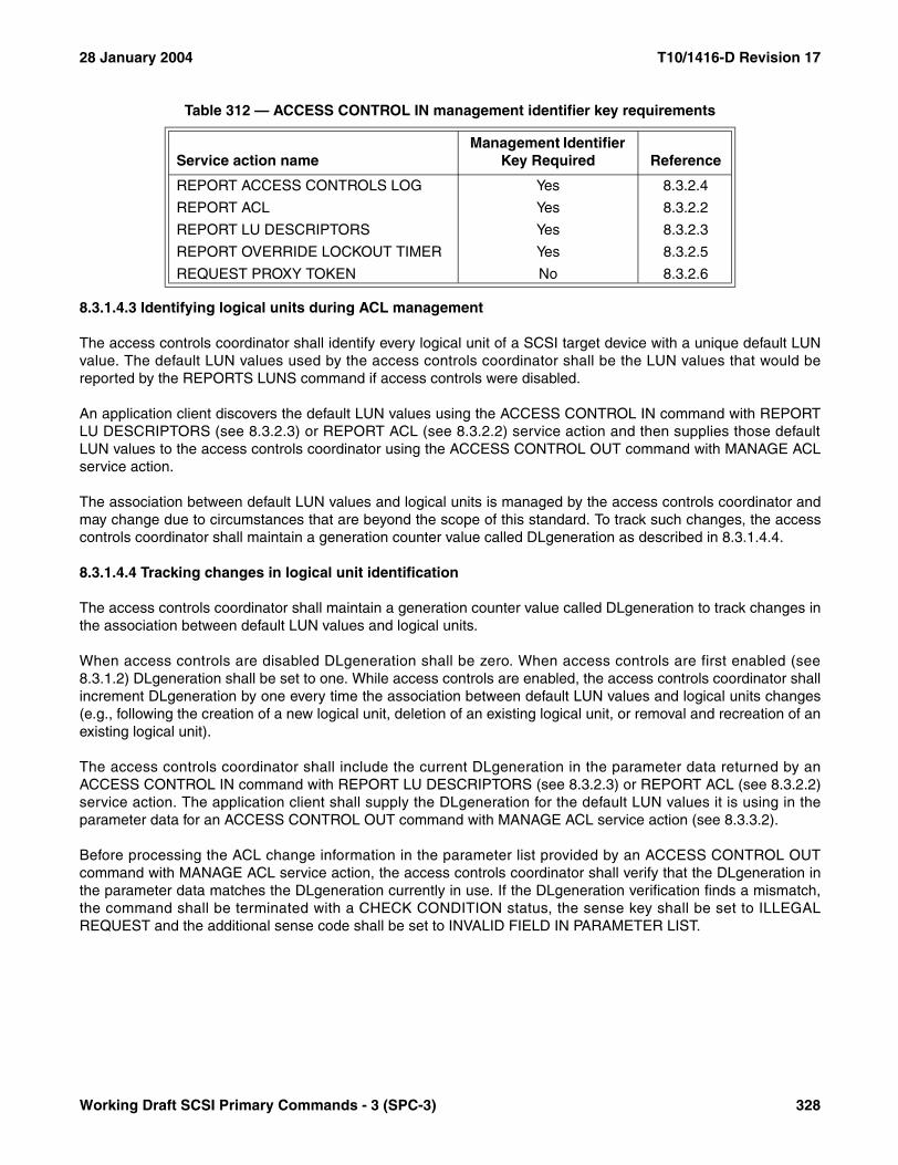
28 January 2004 T10/1416-D Revision 17
8.3.1.4.3 Identifying logical units during ACL management
The access controls coordinator shall identify every logical unit of a SCSI target device with a unique default LUNvalue. The default LUN values used by the access controls coordinator shall be the LUN values that would bereported by the REPORTS LUNS command if access controls were disabled.
An application client discovers the default LUN values using the ACCESS CONTROL IN command with REPORTLU DESCRIPTORS (see 8.3.2.3) or REPORT ACL (see 8.3.2.2) service action and then supplies those defaultLUN values to the access controls coordinator using the ACCESS CONTROL OUT command with MANAGE ACLservice action.
The association between default LUN values and logical units is managed by the access controls coordinator andmay change due to circumstances that are beyond the scope of this standard. To track such changes, the accesscontrols coordinator shall maintain a generation counter value called DLgeneration as described in 8.3.1.4.4.
8.3.1.4.4 Tracking changes in logical unit identification
The access controls coordinator shall maintain a generation counter value called DLgeneration to track changes inthe association between default LUN values and logical units.
When access controls are disabled DLgeneration shall be zero. When access controls are first enabled (see8.3.1.2) DLgeneration shall be set to one. While access controls are enabled, the access controls coordinator shallincrement DLgeneration by one every time the association between default LUN values and logical units changes(e.g., following the creation of a new logical unit, deletion of an existing logical unit, or removal and recreation of anexisting logical unit).
The access controls coordinator shall include the current DLgeneration in the parameter data returned by anACCESS CONTROL IN command with REPORT LU DESCRIPTORS (see 8.3.2.3) or REPORT ACL (see 8.3.2.2)service action. The application client shall supply the DLgeneration for the default LUN values it is using in theparameter data for an ACCESS CONTROL OUT command with MANAGE ACL service action (see 8.3.3.2).
Before processing the ACL change information in the parameter list provided by an ACCESS CONTROL OUTcommand with MANAGE ACL service action, the access controls coordinator shall verify that the DLgeneration inthe parameter data matches the DLgeneration currently in use. If the DLgeneration verification finds a mismatch,the command shall be terminated with a CHECK CONDITION status, the sense key shall be set to ILLEGALREQUEST and the additional sense code shall be set to INVALID FIELD IN PARAMETER LIST.
Table 312 — ACCESS CONTROL IN management identifier key requirements
Service action nameManagement Identifier
Key Required Reference
REPORT ACCESS CONTROLS LOG Yes 8.3.2.4
REPORT ACL Yes 8.3.2.2
REPORT LU DESCRIPTORS Yes 8.3.2.3
REPORT OVERRIDE LOCKOUT TIMER Yes 8.3.2.5
REQUEST PROXY TOKEN No 8.3.2.6
Working Draft SCSI Primary Commands - 3 (SPC-3) 328

T10/1416-D Revision 17 28 January 2004
8.3.1.5 Enrolling AccessIDs
8.3.1.5.1 Enrollment states
8.3.1.5.1.1 Summary of enrollment states
Application clients enroll an initiator port AccessID with the access controls coordinator to be allowed to accesslogical units listed in the ACE having the same AccessID type access identifier. The ACCESS CONTROL OUTcommand with ACCESS ID ENROLL service action (see 8.3.3.4) is used to enroll an AccessID. An initiator portshall be in one of three states with respect to such an enrollment:
a) Not-enrolled: The state for an initiator port before the first ACCESS CONTROL OUT command with ACCESS ID ENROLL service action is sent to the access controls coordinator. Also the state for an initiator port following successful completion of an ACCESS CONTROL OUT command with CANCEL ENROLLMENT service action (see 8.3.3.5);
b) Enrolled: The state for an initiator port following successful completion of an ACCESS CONTROL OUT command with ACCESS ID ENROLL service action; or
c) Pending-enrolled: The state for an enrolled initiator port following:A) Events in the service delivery subsystem described in 8.3.1.12; or B) Successful completion of an ACCESS CONTROL OUT command with MANAGE ACL service action
from any initiator port with the FLUSH bit set to one (see 8.3.3.2).
8.3.1.5.1.2 Not-enrolled state
The access controls coordinator shall place an initiator port in the not-enrolled state when it first detects the receiptof a SCSI command or task management function from that initiator port. The initiator port shall remain in thenot-enrolled state until successful completion of an ACCESS CONTROL OUT command with ACCESS IDENROLL service action (see 8.3.3.5).
When in the not-enrolled state, an initiator port shall only have access to logical units on the basis of a TransportID(see 8.3.1.3.2) or on the basis of proxy tokens (see 8.3.1.6.2.1).
The access controls coordinator changes an initiator port from the enrolled state or pending-enrolled state to thenot-enrolled state in response to the following events:
a) Successful completion of the ACCESS CONTROL OUT command with CANCEL ENROLLMENT service action (see 8.3.3.5) shall change the state to not-enrolled; or
b) Successful completion of an ACCESS CONTROL OUT command with MANAGE ACL service action (see 8.3.3.2) that replaces the ACL entry for the enrolled AccessID as follows:A) If the NOCNCL bit (see 8.3.3.2.2) is set to zero in the ACCESS CONTROL OUT command with
MANAGE ACL service action parameter data, the state shall change to not-enrolled; orB) If the NOCNCL bit is set to one, the state may change to not-enrolled based on vendor specific criteria.
An application client for an enrolled initiator port may discover that the initiator port has transitioned to thenot-enrolled state as a result of actions taken by a third-party (e.g., an ACCESS CONTROL OUT command withMANAGE ACL service action performed by another initiator port or a logical unit reset). Placing an enrolled initiatorin the not-enrolled state indicates that the ACE defining that initiator port’s logical unit access has changed (e.g.,previous relationships between logical units and LUN values may no longer apply).
If an application client detects this loss of enrollment on an initiator port, it may take recovery actions. However,such actions may be disruptive for the SCSI initiator device and may not be required. Use of the not-enrolled stateis avoidable if the application client that sends the ACCESS CONTROL OUT command with MANAGE ACL service
329 Working Draft SCSI Primary Commands - 3 (SPC-3)

28 January 2004 T10/1416-D Revision 17
action determines that its requested changes to the ACL do not alter the existing relationships between logicalunits and LUN values in any existing ACEs with AccessID type access identifiers and sets the NOCNCL bit to one,recommending that initiator ports be left in their current enrollment state.
The access controls coordinator selects from the following options for responding to a NOCNCL bit set to one in avendor specific manner:
a) Honor the recommendation (results in the minimum effects on SCSI initiator devices and requires no extra actions on the part of the access controls coordinator);
b) Ignore the recommendation and always place initiator ports in the non-enrolled state (results in the maximum disruption for SCSI initiator devices, but requires no extra resources on the part of the access controls coordinator); or
c) Ignore the recommendation and examine the current and new ACEs to determine if an initiator port should be placed in the non-enrolled state.
If the application client that sends the ACCESS CONTROL OUT command with MANAGE ACL service action isunable to determine whether the ACE logical unit relationships are altered as a result of processing the command,then it should set the NOCNCL bit to zero and it should coordinate the ACL change with the application clients foraffected initiator ports to ensure proper data integrity. Such coordination is beyond the scope of this standard.
8.3.1.5.1.3 Enrolled state
The access controls coordinator shall place an initiator port in the enrolled state (i.e., enroll the initiator port)following successful completion of the ACCESS CONTROL OUT command with ACCESS ID ENROLL serviceaction (see 8.3.3.4). The ACCESS CONTROL OUT command with ACCESS ID ENROLL service action issuccessful only if:
a) The initiator port was in the not-enrolled state and the AccessID in the ACCESS CONTROL OUT command with ACCESS ID ENROLL service action parameter data matches the access identifier in an ACE. This results in the initiator port being enrolled and allowed access to the logical units specified in the LUACDs in the ACE (see 8.3.1.3); or
b) The initiator port was in the enrolled state or pending-enrolled state and the AccessID in the ACCESS CONTROL OUT command with ACCESS ID ENROLL service action parameter data matches the current enrolled AccessID for the initiator port.
If the initiator port was in the enrolled state or pending-enrolled state and the AccessID in the ACCESS CONTROLOUT command with ACCESS ID ENROLL service action parameter data does not match the current enrolledAccessID for the initiator port, then the command shall be terminated with CHECK CONDITION status. The sensekey shall be set to ILLEGAL REQUEST and the additional sense code shall be set to ACCESS DENIED -ENROLLMENT CONFLICT. If the initiator port was in the enrolled state it shall be transitioned to thepending-enrolled state.
Transitions from the enrolled state to the not-enrolled state are described in 8.3.1.5.1.2. Transitions from theenrolled state to the pending-enrolled state are described in 8.3.1.5.1.4.
NOTE 72 - This standard does not preclude implicit enrollments through mechanisms in the service deliverysubsystem. Such mechanisms should perform implicit enrollments after identification by TransportID and should failin the case where there are ACL conflicts as described in 8.3.1.5.2.
Working Draft SCSI Primary Commands - 3 (SPC-3) 330
T10/1416-D Revision 17 28 January 2004
8.3.1.5.1.4 Pending-enrolled state
The access controls coordinator shall place an initiator port in the pending-enrolled state if that initiator portcurrently is in the enrolled state, and in response to the following:
a) A logical unit reset;b) An I_T nexus loss involving that initiator port; orc) Successful completion of an ACCESS CONTROL OUT command with MANAGE ACL service action
where the FLUSH bit is set to one in the parameter data.
While in the pending-enrolled state, the initiator port’s access to logical units is limited as described in 8.3.1.7.
8.3.1.5.2 ACL LUN conflict resolution
ACL LUN conflicts may occur if:
a) An application client for an initiator port in the not-enrolled state attempts to enroll an AccessID using the ACCESS CONTROL OUT command with ACCESS ID ENROLL service action (see 8.3.3.4); or
b) An ACCESS CONTROL OUT command with MANAGE ACL service action (see 8.3.3.2) attempts to change the ACL with the result that it conflicts with existing enrollments (see 8.3.1.5) or proxy LUN assign-ments (see 8.3.1.6.2.2).
Three types of ACL LUN conflicts may occur:
a) The TransportID ACE (see 8.3.1.3) and the AccessID ACE for the initiator port each contain a LUACD with the same LUN value but with different logical unit references;
b) The TransportID ACE and the AccessID ACE for the initiator port each contain a LUACD with the different LUN values but with the same logical unit references; or
c) The enrolling initiator port has proxy access rights to a logical unit addressed with a LUN value that equals a LUN value in a LUACD in the AccessID ACE for the initiator port.
If an ACL LUN conflict occurs during the processing of an ACCESS CONTROL OUT command with MANAGE ACLservice action the command shall be terminated with a CHECK CONDITION status (see 8.3.3.2.2).
If an ACL LUN conflict occurs during the processing of an ACCESS CONTROL OUT command with ACCESS IDENROLL service action, the following actions shall be taken as part of the handling of the enrollment function:
a) The ACCESS CONTROL OUT command with ACCESS ID ENROLL service action shall be terminated with CHECK CONDITION status, the sense key shall be set to ILLEGAL REQUEST, the additional sense code shall be set to ACCESS DENIED - ACL LUN CONFLICT;
b) The initiator port shall remain in the not-enrolled state; andc) If the ACL LUN conflict is not the result of proxy access rights, the access controls coordinator shall record
the event in the access controls log as described in 8.3.1.10.
8.3.1.6 Granting and revoking access rights
8.3.1.6.1 Non-proxy access rights
The ACCESS CONTROL OUT command with MANAGE ACL service action (see 8.3.3.2) adds or replaces ACEsin the ACL (see 8.3.1.3). One ACE describes the logical unit access allowed by one access identifier (see8.3.1.3.2) and the LUN values to be used in addressing the accessible logical units. The access identifier specifiesthe initiator port(s) permitted access to the logical units described by the ACE.
331 Working Draft SCSI Primary Commands - 3 (SPC-3)
28 January 2004 T10/1416-D Revision 17
With the exception of proxy access rights (see 8.3.1.6.2), access rights are granted by:
a) Adding a new ACE to the ACL; orb) Replacing an existing ACE with an ACE that includes additional LUACDs.
With the exception of proxy access rights, access rights are revoked by:
a) Removing an ACE from the ACL; or b) Replacing an existing ACE with an ACE that removes one or more LUACDs.
When an ACE is added or replaced the requirements stated in 8.3.1.5.1.2 and 8.3.1.11 apply.
8.3.1.6.2 Proxy access
8.3.1.6.2.1 Proxy tokens
An application client with access rights to a logical unit via an initiator port on the basis of an ACE in the ACL (see8.3.1.6.1) may temporarily share that access with third parties using the proxy access mechanism. The applicationclient uses the ACCESS CONTROL IN command with REQUEST PROXY TOKEN service action (see 8.3.2.6) torequest that the access control coordinator generate a proxy token for the logical unit specified by the LUN value inthe CDB.
The access controls coordinator generates the proxy token in a vendor specific manner. For a specific SCSI targetdevice, all active proxy token values should be unique. Proxy token values should be reused as infrequently aspossible to prevent proxy tokens that have been used and released from being given unintended meaning.
Power cycles, hard resets, logical unit resets, and I_T nexus losses shall not affect the validity and proxy accessrights of proxy tokens (see 8.3.1.12). A proxy token shall remain valid and retain the same proxy access rights untilone of the following occurs:
a) An application client with access rights to a logical unit via an initiator port based on an ACE in the ACL revokes the proxy token using:A) The ACCESS CONTROL OUT command with REVOKE PROXY TOKEN service action (see 8.3.3.9);
orB) The ACCESS CONTROL OUT command with REVOKE ALL PROXY TOKENS service action (see
8.3.3.10);or
b) An application client issues the ACCESS CONTROL OUT command with MANAGE ACL service action (see 8.3.3.2) with parameter data containing the Revoke Proxy Token ACE page (see 8.3.3.2.4) or Revoke All Proxy Tokens ACE page (see 8.3.3.2.5).
8.3.1.6.2.2 Proxy LUNs
To extend proxy access rights to a third party, an application client forwards a proxy token (see 8.3.1.6.2.2) to thethird party (e.g., in a target descriptor in the parameter data of the EXTENDED COPY command).
The third party sends the access controls coordinator an ACCESS CONTROL OUT command with ASSIGNPROXY LUN service action (see 8.3.3.11) specifying the proxy token to request creation of a proxy access right tothe referenced logical unit. The access controls coordinator determines the referenced logical unit from the proxytoken value. The third party is unaware of the exact logical unit to which it is requesting access.
Working Draft SCSI Primary Commands - 3 (SPC-3) 332

T10/1416-D Revision 17 28 January 2004
The parameter data for the ACCESS CONTROL OUT command with ASSIGN PROXY LUN service actionincludes the LUN value that the third party intends to use when accessing the referenced logical unit. The resultingLUN value is called a proxy LUN. If the ACCESS CONTROL OUT command with ASSIGN PROXY LUN serviceaction is successful, the proxy LUN becomes the third party’s mechanism for accessing the logical unit by proxy.
Once assigned, a proxy LUN shall remain valid until one of the following occurs:
a) The third party releases the proxy LUN value using the ACCESS CONTROL OUT command with RELEASE PROXY LUN service action (see 8.3.3.12);
b) The proxy token is made invalid as described in 8.3.1.6.2.1; orc) A logical unit reset or I_T nexus loss of the I_T nexus used to assign the proxy LUN (see 8.3.1.12).
The third party may reissue the ACCESS CONTROL OUT command with ASSIGN PROXY LUN service action inan attempt to re-establish its proxy access rights. If the cause of the proxy token becoming invalid was temporary,the reissued command should succeed. The access controls coordinator shall process the request as described in8.3.1.6.2.1 without reference to any previous assignment of the proxy LUN value.
8.3.1.7 Verifying access rights
When access controls are enabled (see 8.3.1.2), access rights for an initiator port shall be validated as describedin this subclause.
All the linked commands in a single task shall be processed based on the ACL that is in effect when the task firstenters the task enabled state. Relationships between access controls and tasks in a task set are described in8.3.1.11.1.
All commands shall be processed as if access controls were not present if the ACL (see 8.3.1.3) allows the initiatorport access to the addressed logical unit as a result of one of the following conditions:
a) The ACL contains an ACE containing a TransportID type access identifier (see 8.3.1.3.2) for the initiator port and that ACE includes a LUACD with LUN value matching the addressed LUN;
b) The initiator port is in the enrolled state (see 8.3.1.5.1.3) under an AccessID, the ACL contains an ACE containing that AccessID as an access identifier, and that ACE includes a LUACD with LUN value matching the addressed LUN; or
c) The addressed LUN matches a proxy LUN value (see 8.3.1.6.2.2) assigned using the ACCESS CONTROL OUT command with ASSIGN PROXY LUN service action (see 8.3.3.11) and the proxy token (see 8.3.1.6.2.1) used to assign the proxy LUN value is still valid.
If the initiator port is in the pending-enrolled state (see 8.3.1.5.1.4) under an AccessID, the ACL contains an ACEcontaining that AccessID as an access identifier, and that ACE includes a LUACD with LUN value matching theaddressed LUN, then commands shall be processed as follows:
a) INQUIRY, REPORT LUNS, ACCESS CONTROL OUT and ACCESS CONTROL IN commands shall be processed as if access controls were not present;
b) A REQUEST SENSE command shall be processed as if access controls were not present as described in 6.25, except in the case where a sense key of NO SENSE would be returned. In this case, the REQUEST SENSE command shall return a sense key of ILLEGAL REQUEST and the additional sense code of ACCESS DENIED - INITIATOR PENDING-ENROLLED; and
c) Any other command shall be terminated with a CHECK CONDITION status, the sense key shall be set to ILLEGAL REQUEST and the additional sense code shall be set to ACCESS DENIED - INITIATOR PENDING-ENROLLED.
333 Working Draft SCSI Primary Commands - 3 (SPC-3)

28 January 2004 T10/1416-D Revision 17
An application client should respond to the ACCESS DENIED - INITIATOR PENDING-ENROLLED additionalsense code by sending an ACCESS CONTROL OUT command with ACCESS ID ENROLL service action. If thecommand succeeds, the application client may retry the failed command.
If an INQUIRY command is addressed to a LUN for which there is no matching LUN value in any LUACD in anyACE allowing the initiator port logical unit access rights, the standard INQUIRY data (see 6.4.2) PERIPHERAL DEVICE
TYPE field shall be set to 1Fh and the PERIPHERAL QUALIFIER field shall be set to 011b (i.e., the device server is notcapable of supporting a device at this logical unit).
The parameter data returned in response to a REPORT LUNS command addressed to LUN 0 or to the REPORTLUNS well known logical unit shall return only the list of LUN values that are associated to accessible logical unitsaccording to the following criteria:
a) If the initiator port is in the enrolled state or pending-enrolled state, the REPORT LUNS parameter data shall include any LUN values found in LUACDs in the ACE containing the AccessID enrolled by the initiator port;
b) If the initiator port (in any enrollment state) has a TransportID found in the access identifier of an ACE, the REPORT LUNS parameter data shall include any LUN values found in LUACDs in that ACE; and
c) If the initiator port (in any enrollment state) has access to any proxy LUNs (see 8.3.1.6.2.2), those LUN values shall be included in the REPORT LUNS parameter data.
The parameter data returned in response to a REPORT LUNS command that describes well known logical unitsshall not be affected by access controls.
If the initiator port is in the not-enrolled state and is not allowed access to any logical unit as result of its Trans-portID or as a result of a proxy LUN assignment, then the REPORT LUNS parameter data shall include only LUN 0and well known logical units, as specified in 6.21.
Except when access controls are disabled, all cases not described previously in this subclause shall result in termi-nation of the command with CHECK CONDITION status, the sense key shall be set to ILLEGAL REQUEST andthe additional sense code shall be set to LOGICAL UNIT NOT SUPPORTED.
8.3.1.8 The management identifier key
8.3.1.8.1 Management identifier key usage
The management identifier key identifies the application that is responsible for managing access controls for aSCSI target device. This identification occurs when the application client specifies a new management identifierkey value in each ACCESS CONTROL OUT command with the MANAGE ACL service action (see 8.3.3.2), andwhen the last specified management identifier key value appears in ACCESS CONTROL IN and ACCESSCONTROL OUT service actions as required in 8.3.1.4.2.
To allow for failure scenarios where the management identifier key value has been lost, an override procedureinvolving a timer is described in 8.3.1.8.2.
Use of the management identifier key has the following features:
a) Management of access controls is associated with those application clients that provide the correct management identifier key without regard for the initiator port from which the command was received; and
b) Only an application client that has knowledge of the management identifier key may change the ACL, allowing the management of access controls to be limited to specific applications and application clients.
Working Draft SCSI Primary Commands - 3 (SPC-3) 334
T10/1416-D Revision 17 28 January 2004
8.3.1.8.2 Overriding the management identifier key
8.3.1.8.2.1 The OVERRIDE MGMT ID KEY service action
If the management identifier key needs to be replaced and the current management identifier key is not available,then the ACCESS CONTROL OUT command with OVERRIDE MGMT ID KEY service action (see 8.3.3.8) may beused to force the management identifier key to a known value.
The ACCESS CONTROL OUT command with OVERRIDE MGMT ID KEY service action should be used only forfailure recovery. If failure recovery is not required, the ACCESS CONTROL OUT command with MANAGE ACLservice action should be used.
To protect the management identifier key from unauthorized overrides, the access controls coordinator shall restrictuse of the ACCESS CONTROL OUT command with OVERRIDE MGMT ID KEY service action based on the valueof the override lockout timer (see 8.3.1.8.2.2).
When the override lockout timer is not zero, an ACCESS CONTROL OUT command with OVERRIDE MGMT IDKEY service action shall be terminated with CHECK CONDITION status, the sense key shall be set to ILLEGALREQUEST and the additional sense code shall be set to INVALID FIELD IN CDB.
When the override lockout timer is zero, an ACCESS CONTROL OUT command with OVERRIDE MGMT ID KEYservice action shall be processed as described in 8.3.3.8.
The access controls coordinator shall log the receipt of each ACCESS CONTROL OUT command with OVERRIDEMGMT ID KEY service action and its success or failure as described in 8.3.1.10.
8.3.1.8.2.2 The override lockout timer
The access controls coordinator shall maintain the override lockout timer capable of counting up to 65 535seconds. When the override lockout timer is not zero it shall be decreased by one nominally once per second butno more frequently than once every 800 milliseconds until the value reaches zero. When the override lockout timeris zero, it shall not be changed except as the result of commands sent by an application client.
The ACCESS CONTROL OUT command with MANAGE OVERRIDE LOCKOUT TIMER service action managesthe state of the override lockout timer (see 8.3.3.7), performing one of the following functions:
a) If the incorrect management identifier key is supplied or if no parameter data is sent, the access controls coordinator shall reset the override lockout timer to the last received initial override lockout timer value; or
b) If the correct management identifier key is supplied, then the access controls coordinator shall do the following:1) Save the initial override lockout timer value supplied in the parameter data; and2) Reset the override lockout timer to the new initial value.
Setting the initial override lockout timer value to zero disables the override lockout timer and allows the ACCESSCONTROL OUT command with OVERRIDE MGMT KEY service action to succeed at any time.
Any application that knows the management identifier key may establish an initial override lockout timer value ofsufficient duration (up to about 18 hours). Maintaining a non-zero override lockout timer value may be accom-plished without knowing the management identifier key or transporting the management identifier key on theservice delivery subsystem. Attempts to establish a zero initial override lockout timer value that are not accom-panied by the correct management identifier key result in decreasing the probability that a subsequent ACCESSCONTROL OUT command with OVERRIDE MGMT ID KEY service action is able to succeed by resetting theoverride lockout timer.
335 Working Draft SCSI Primary Commands - 3 (SPC-3)
28 January 2004 T10/1416-D Revision 17
After a logical unit reset, the override lock timer shall be set to the initial override lockout timer value within tenseconds of the non-volatile memory containing the initial override lockout timer value becoming available.
The ACCESS CONTROL IN command with REPORT OVERRIDE LOCKOUT TIMER may be used to discover thestate of the override lockout timer.
8.3.1.9 Reporting access control information
Specific service actions of the ACCESS CONTROL IN command may be used by an application client to request areport from the access controls coordinator about its access controls data and state.
The ACCESS CONTROL IN command with REPORT ACL service action (see 8.3.2.2) returns the ACL (see8.3.1.3). The information reported includes the following:
a) The list of access identifiers (see 8.3.1.3.2) and the associated LUACDs (see 8.3.1.3.3) currently in effect; and
b) The list of proxy tokens (see 8.3.1.6.2.1) currently in effect.
The ACCESS CONTROL IN command with REPORT ACCESS CONTROLS LOG service action (see 8.3.2.4)returns the contents of the access controls log (see 8.3.1.10).
The ACCESS CONTROL IN command with REPORT OVERRIDE LOCKOUT TIMER service action (see 8.3.2.5)reports on the state of the override lockout timer (see 8.3.1.8.2.2).
8.3.1.10 Access controls log
The access controls log is a record of events maintained by the access controls coordinator.
The access controls log has three portions, each recording a different class of events:
a) invalid key events: mismatches between the management identifier key (see 8.3.1.8) specified by a service action and the current value maintained by the access controls coordinator;
b) key override events: attempts to override the management identifier key (see 8.3.1.8.2.1), whether the attempt fails or succeeds; and
c) ACL LUN conflict events: (see 8.3.1.5.2).
Each portion of the log is required to contain a counter of the events. When a SCSI target device is manufactured,all counters shall be set to zero. When access controls are disabled, all counters except the key override eventscounter shall be set to zero. Each counter shall be incremented by one whenever the relevant event occurs.
Each log portion may contain additional records with more specific information about each event. When theresources for additional log records are exhausted, the access controls coordinator shall preserve the mostrecently added log records in preference to older log records.
Log records contain a TIME STAMP field whose contents are vendor specific. If the access controls coordinator hasno time stamp resources the TIME STAMP field shall be set to zero. If time stamp values are provided, the sametiming clock and time stamp format shall be used for all access controls log entries.
Invalid key events occur whenever an access controls command requires the checking of an application clientsupplied management identifier key against the current management identifier key saved by the access controlscoordinator and the two values fail to match. When such an event occurs, the access controls coordinator shallincrement the invalid keys counter by one. If the log has additional resources to record event details, the accesscontrols coordinator shall add an invalid keys log record (containing the information defined in 8.3.2.4.2.3)describing the event.
Working Draft SCSI Primary Commands - 3 (SPC-3) 336
T10/1416-D Revision 17 28 January 2004
Key override events occur when the access controls coordinator receives the ACCESS CONTROL OUT commandwith OVERRIDE MGMT KEY service action (see 8.3.3.8). When such an event occurs, the access controls coordi-nator shall increment the key overrides counter by one without regard for whether the command succeeds or fails.If the log has additional resources to record event details, the access controls coordinator shall add an keyoverrides log record (containing the information defined in 8.3.2.4.2.2) describing the event.
ACL LUN conflict events occur as specified in 8.3.1.5.2. When such an event occurs, the access controls coordi-nator shall increment the ACL LUN conflicts counter by one. If the log has additional resources to record eventdetails, the access controls coordinator shall add an ACL LUN conflicts log record (containing the informationdefined in 8.3.2.4.2.4) describing the event.
Selected portions of the access controls log may be requested by an application client using the ACCESSCONTROL IN command with REPORT ACCESS CONTROLS LOG service action (see 8.3.2.4). With theexception of the key overrides portion, selected portions of the log may be cleared and the counters reset to zerousing the ACCESS CONTROL OUT command with CLEAR ACCESS CONTROLS LOG service action (see8.3.3.6).
8.3.1.11 Interactions of access controls and other features
8.3.1.11.1 Task set management and access controls
Upon successful completion of an ACCESS CONTROL OUT command with MANAGE ACL service action (see8.3.3.2), the specified ACL (see 8.3.1.3) shall apply to all tasks that subsequently enter the task enabled state.Tasks that have modified SCSI target device state information (e.g., media, mode pages, and log pages) shall notbe affected by an ACCESS CONTROL OUT command that subsequently enters the task enabled state. Tasks inthe task enabled state that have not modified SCSI target device state information may or may not be affected byan ACCESS CONTROL OUT command that subsequently enters the task enabled state. The ACL in effect prior towhen the ACCESS CONTROL OUT command with MANAGE ACL or DISABLE ACCESS CONTROLS serviceaction entered the task enabled state shall apply to all tasks that are not affected by the ACCESS CONTROL OUTcommand.
All the operations performed by a task shall complete under the control of a single ACL, either the state in effectprior to processing of the ACCESS CONTROL OUT command or the state in effect following processing of theACCESS CONTROL OUT command. After a task enters the task enabled state for the first time changing theaccess control state from disabled to enabled (see 8.3.1.2) shall have no effect on the task.
Multiple access control commands, both ACCESS CONTROL IN and ACCESS CONTROL OUT, may be in thetask set concurrently. The order of processing of such commands is defined by the task set management require-ments (see SAM-2), but each command shall be processed as a single indivisible command without any inter-leaving of actions that may be required by other access control commands.
8.3.1.11.2 Existing reservations and ACL changes
If a logical unit is reserved by one I_T nexus and that logical unit becomes accessible to another I_T nexus as aresult of an access control command, there shall be no changes in the reservation of that logical unit.
If a logical unit is reserved by an I_T nexus and that logical unit becomes inaccessible to that I_T nexus as a resultof an access control command or other access control related event, there shall be no changes in the reservation.Existing persistent reservations mechanisms allow for other SCSI initiator devices with access to that logical unit toclear the reservation.
337 Working Draft SCSI Primary Commands - 3 (SPC-3)

28 January 2004 T10/1416-D Revision 17
8.3.1.12 Access controls information persistence and memory usage requirements
If a SCSI target device supports access controls, then the SCSI target device shall contain an access controlscoordinator that shall maintain the following information in nonvolatile memory:
a) Whether access controls are enabled or disabled; andb) The access controls data that table 313 and table 314 require to persistent across power cycles, hard
resets, and logical unit resets.
If the access control coordinator’s nonvolatile memory is not ready and the access controls coordinator is unable todetermine that access controls are disabled, the device servers for all logical units shall terminate all commandsexcept INQUIRY and REQUEST SENSE commands with a CHECK CONDITION status, the sense key shall be setto NOT READY and additional sense data shall be set as described in table 165 (see 6.29).
Following an I_T nexus loss, a previously enrolled initiator port shall be placed in the pending-enrolled state, if thatinitiator port was associated with the lost I_T nexus. Following a logical unit reset, all previously enrolled initiatorports shall be placed in the pending-enrolled state.
The information shown in table 313 shall be maintained by the access controls coordinator.
Table 313 — Mandatory access controls resources
Information DescriptionSize
(in bits)
Persistent Across Power Cycles, Hard Resets, and Logical Unit
Resets
One ACL (see 8.3.1.3) containing at least one ACE contain-ing one access identifier (see 8.3.1.3.2), and at least one LUACD (see 8.3.1.3.3)
VS Yes
The Enrollment State for each initiator port (see 8.3.1.5.1) VS Yes
Management Identifier Key (see 8.3.1.8) 64 Yes
Default LUNs Generation (DLgeneration, see 8.3.1.4.4) 32 Yes
Override Lockout Timer (see 8.3.1.8.2.2) 16 No
Initial Override Lockout Timer value (see 8.3.1.8.2.2) 16 Yes
Access Controls Log Event Counters (see 8.3.1.10) contain-ing at least the following:
a) Key Overrides Counter;b) Invalid Keys Counter; andc) ACL LUN Conflicts Counter
161616
Yes
YesYesYes
Working Draft SCSI Primary Commands - 3 (SPC-3) 338

T10/1416-D Revision 17 28 January 2004
Optionally, the access controls coordinator may maintain the information shown in table 314.
At the time of manufacturer, the ACL shall be empty, all values shown in table 313 shall be zero, additional accesscontrol log structures shall be empty and there shall be no valid proxy tokens.
Table 314 — Optional access controls resources
Information DescriptionSize
(in bits)
Persistent Across Power Cycles,
Hard Resets, and Logical Unit
Resets
One or more proxy tokens (see 8.3.1.6.2.1) 64 Yes
One or more proxy LUNs (see 8.3.1.6.2.2) 64 No
Access controls log event records (see 8.3.1.10) for:a) Key Overrides events;b) Invalid Keys events; andc) ACL LUN Conflicts events
(see 8.3.2.4.2.2)(see 8.3.2.4.2.3)(see 8.3.2.4.2.4)
YesYesYes
339 Working Draft SCSI Primary Commands - 3 (SPC-3)

28 January 2004 T10/1416-D Revision 17
8.3.1.13 Access identifier formats
8.3.1.13.1 Access identifier type
The ACCESS IDENTIFIER TYPE field (see table 315) indicates the format and usage of the access identifier.
8.3.1.13.2 AccessID access identifiers
AccessID access identifiers shall have the format shown in table 316.
The ACCESSID field contains a value that identifies the AccessID type ACE in which the AccessID access identifierappears. Within the ACL, no two ACEs shall contain the same AccessID.
Table 315 — Access Identifier types
Access Identifier
Type
Access Identifier Name
Access Identifier Format
Reference
00h AccessID 8.3.1.13.201h TransportID 7.5.4
02h-7Fh Reserved80h-FFh Vendor specific
Table 316 — AccessID access identifier format
BitByte
7 6 5 4 3 2 1 0
0ACCESSID
15
16Reserved
23
Working Draft SCSI Primary Commands - 3 (SPC-3) 340
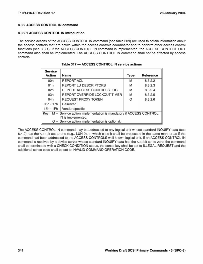
T10/1416-D Revision 17 28 January 2004
8.3.2 ACCESS CONTROL IN command
8.3.2.1 ACCESS CONTROL IN introduction
The service actions of the ACCESS CONTROL IN command (see table 309) are used to obtain information aboutthe access controls that are active within the access controls coordinator and to perform other access controlfunctions (see 8.3.1). If the ACCESS CONTROL IN command is implemented, the ACCESS CONTROL OUTcommand also shall be implemented. The ACCESS CONTROL IN command shall not be affected by accesscontrols.
The ACCESS CONTROL IN command may be addressed to any logical unit whose standard INQUIRY data (see6.4.2) has the ACC bit set to one (e.g., LUN 0), in which case it shall be processed in the same manner as if thecommand had been addressed to the ACCESS CONTROLS well known logical unit. If an ACCESS CONTROL INcommand is received by a device server whose standard INQUIRY data has the ACC bit set to zero, the commandshall be terminated with a CHECK CONDITION status, the sense key shall be set to ILLEGAL REQUEST and theadditional sense code shall be set to INVALID COMMAND OPERATION CODE.
Table 317 — ACCESS CONTROL IN service actions
Service Action Name Type Reference
00h REPORT ACL M 8.3.2.201h REPORT LU DESCRIPTORS M 8.3.2.302h REPORT ACCESS CONTROLS LOG M 8.3.2.403h REPORT OVERRIDE LOCKOUT TIMER M 8.3.2.504h REQUEST PROXY TOKEN O 8.3.2.6
05h - 17h Reserved18h - 1Fh Vendor specificKey: M = Service action implementation is mandatory if ACCESS CONTROL
IN is implemented.O = Service action implementation is optional.
341 Working Draft SCSI Primary Commands - 3 (SPC-3)
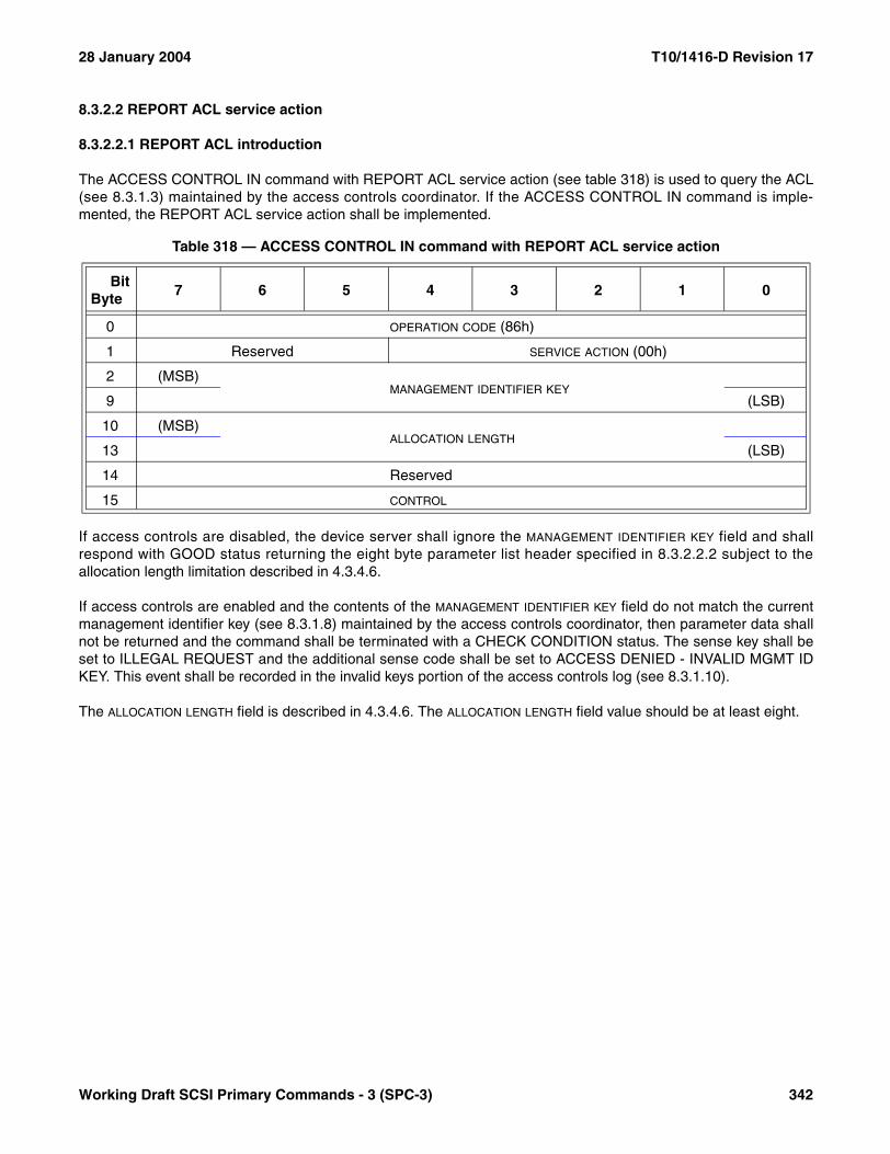
28 January 2004 T10/1416-D Revision 17
8.3.2.2 REPORT ACL service action
8.3.2.2.1 REPORT ACL introduction
The ACCESS CONTROL IN command with REPORT ACL service action (see table 318) is used to query the ACL(see 8.3.1.3) maintained by the access controls coordinator. If the ACCESS CONTROL IN command is imple-mented, the REPORT ACL service action shall be implemented.
If access controls are disabled, the device server shall ignore the MANAGEMENT IDENTIFIER KEY field and shallrespond with GOOD status returning the eight byte parameter list header specified in 8.3.2.2.2 subject to theallocation length limitation described in 4.3.4.6.
If access controls are enabled and the contents of the MANAGEMENT IDENTIFIER KEY field do not match the currentmanagement identifier key (see 8.3.1.8) maintained by the access controls coordinator, then parameter data shallnot be returned and the command shall be terminated with a CHECK CONDITION status. The sense key shall beset to ILLEGAL REQUEST and the additional sense code shall be set to ACCESS DENIED - INVALID MGMT IDKEY. This event shall be recorded in the invalid keys portion of the access controls log (see 8.3.1.10).
The ALLOCATION LENGTH field is described in 4.3.4.6. The ALLOCATION LENGTH field value should be at least eight.
Table 318 — ACCESS CONTROL IN command with REPORT ACL service action
BitByte
7 6 5 4 3 2 1 0
0 OPERATION CODE (86h)
1 Reserved SERVICE ACTION (00h)
2 (MSB)MANAGEMENT IDENTIFIER KEY
9 (LSB)
10 (MSB)ALLOCATION LENGTH
13 (LSB)
14 Reserved
15 CONTROL
Working Draft SCSI Primary Commands - 3 (SPC-3) 342
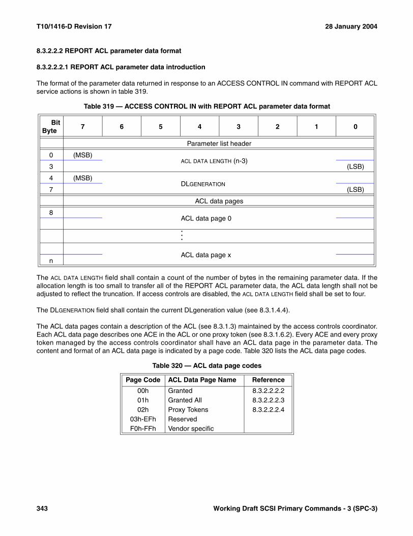
T10/1416-D Revision 17 28 January 2004
8.3.2.2.2 REPORT ACL parameter data format
8.3.2.2.2.1 REPORT ACL parameter data introduction
The format of the parameter data returned in response to an ACCESS CONTROL IN command with REPORT ACLservice actions is shown in table 319.
The ACL DATA LENGTH field shall contain a count of the number of bytes in the remaining parameter data. If theallocation length is too small to transfer all of the REPORT ACL parameter data, the ACL data length shall not beadjusted to reflect the truncation. If access controls are disabled, the ACL DATA LENGTH field shall be set to four.
The DLGENERATION field shall contain the current DLgeneration value (see 8.3.1.4.4).
The ACL data pages contain a description of the ACL (see 8.3.1.3) maintained by the access controls coordinator.Each ACL data page describes one ACE in the ACL or one proxy token (see 8.3.1.6.2). Every ACE and every proxytoken managed by the access controls coordinator shall have an ACL data page in the parameter data. Thecontent and format of an ACL data page is indicated by a page code. Table 320 lists the ACL data page codes.
Table 319 — ACCESS CONTROL IN with REPORT ACL parameter data format
BitByte
7 6 5 4 3 2 1 0
Parameter list header
0 (MSB)ACL DATA LENGTH (n-3)
3 (LSB)
4 (MSB)DLGENERATION
7 (LSB)
ACL data pages
8ACL data page 0
.
.
.
ACL data page xn
Table 320 — ACL data page codes
Page Code ACL Data Page Name Reference
00h Granted 8.3.2.2.2.201h Granted All 8.3.2.2.2.302h Proxy Tokens 8.3.2.2.2.4
03h-EFh ReservedF0h-FFh Vendor specific
343 Working Draft SCSI Primary Commands - 3 (SPC-3)

28 January 2004 T10/1416-D Revision 17
8.3.2.2.2.2 Granted ACL data page format
The Granted ACL data page (see table 321) describes an ACE that allows access to a specific set of logical unitsvia a list of LUACDs (see 8.3.1.3.3).
The PAGE LENGTH field shall indicate the number of additional bytes required for this ACL data page and shall notbe adjusted to reflect any truncation caused by insufficient allocation length.
The ACCESS IDENTIFIER TYPE field (see 8.3.1.13) indicates the format and usage of the access identifier.
The ACCESS IDENTIFIER LENGTH field indicates the number of bytes following taken up by the ACCESS IDENTIFIER field.The access identifier length shall be at least 24 and shall be a multiple of four.
The ACCESS IDENTIFIER field contains the identifier that the access controls coordinator uses to select the initiatorport(s) that are allowed access to the logical units named by the LUACD descriptors in this ACL data page. Theformat of the ACCESS IDENTIFIER field is specified in table 315 (see 8.3.1.13). One Granted or Granted All (see8.3.2.2.2.3) ACL data page shall be returned for a specific pair of values in the ACCESS IDENTIFIER TYPE and ACCESS
IDENTIFIER fields.
Table 321 — Granted ACL data page format
BitByte
7 6 5 4 3 2 1 0
0 PAGE CODE (00h)
1 Reserved
2 (MSB)PAGE LENGTH (n-3)
3 (LSB)
4 Reserved
5 ACCESS IDENTIFIER TYPE
6 (MSB)ACCESS IDENTIFIER LENGTH (m-7)
7 (LSB)
8ACCESS IDENTIFIER
m
LUACD Descriptors
m+1LUACD descriptor 0
m+20...
n-19LUACD descriptor x
n
Working Draft SCSI Primary Commands - 3 (SPC-3) 344

T10/1416-D Revision 17 28 January 2004
Each LUACD descriptor (see table 322) describes the access allowed to one logical unit based on the accessidentifier. There shall be one LUACD descriptor for each logical unit to which the access identifier allows access.
The ACCESS MODE field (see table 323) indicates the type of access allowed to the logical unit referenced by theDEFAULT LUN field and addressable at the specified LUN value.
The LUN VALUE field indicates the LUN value an accessing application client uses to access the logical unit via theinitiator port to which the LUACD descriptor applies.
The DEFAULT LUN field identifies the logical unit to which access is allowed using the default LUN value described in8.3.1.4.3. The value in the DEFAULT LUN field shall be consistent with the DLGENERATION field contents returned inthe parameter list header (see 8.3.2.2.2).
The LUN VALUE and DEFAULT LUN fields may contain the same value.
Table 322 — Granted ACL data page LUACD descriptor format
BitByte
7 6 5 4 3 2 1 0
0 ACCESS MODE
1Reserved
3
4LUN VALUE
11
12DEFAULT LUN
19
Table 323 — Access mode values
Access Mode Description
00h Normal access01h-EFh ReservedF0h-FFh Vendor specific
345 Working Draft SCSI Primary Commands - 3 (SPC-3)
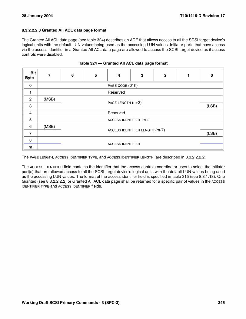
28 January 2004 T10/1416-D Revision 17
8.3.2.2.2.3 Granted All ACL data page format
The Granted All ACL data page (see table 324) describes an ACE that allows access to all the SCSI target device’slogical units with the default LUN values being used as the accessing LUN values. Initiator ports that have accessvia the access identifier in a Granted All ACL data page are allowed to access the SCSI target device as if accesscontrols were disabled.
The PAGE LENGTH, ACCESS IDENTIFIER TYPE, and ACCESS IDENTIFIER LENGTH, are described in 8.3.2.2.2.2.
The ACCESS IDENTIFIER field contains the identifier that the access controls coordinator uses to select the initiatorport(s) that are allowed access to all the SCSI target device’s logical units with the default LUN values being usedas the accessing LUN values. The format of the access identifier field is specified in table 315 (see 8.3.1.13). OneGranted (see 8.3.2.2.2.2) or Granted All ACL data page shall be returned for a specific pair of values in the ACCESS
IDENTIFIER TYPE and ACCESS IDENTIFIER fields.
Table 324 — Granted All ACL data page format
BitByte
7 6 5 4 3 2 1 0
0 PAGE CODE (01h)
1 Reserved
2 (MSB)PAGE LENGTH (m-3)
3 (LSB)
4 Reserved
5 ACCESS IDENTIFIER TYPE
6 (MSB)ACCESS IDENTIFIER LENGTH (m-7)
7 (LSB)
8ACCESS IDENTIFIER
m
Working Draft SCSI Primary Commands - 3 (SPC-3) 346

T10/1416-D Revision 17 28 January 2004
8.3.2.2.2.4 Proxy Tokens ACL data page format
The Proxy Tokens ACL data page (see table 325) describes the proxy tokens (see 8.3.1.6.2) maintained by theaccess controls coordinator.
The PAGE LENGTH field shall indicate the number of additional bytes required for this ACL data page and shall notbe adjusted to reflect any truncation caused by insufficient allocation length.
If there are no active proxy tokens, the access controls coordinator may either not include the Proxy Tokens ACLdata page in the parameter data or may include one such ACL data page containing no proxy token descriptors.
No more than one Proxy Tokens ACL data page shall be included in the parameter data.
Each proxy token descriptor (see table 326) describes the access allowed to one logical unit based on one proxytoken. There shall be one proxy token descriptor for each active proxy token maintained by the access controlscoordinator.
The PROXY TOKEN field indicates the proxy token to which this proxy token descriptor applies.
Table 325 — Proxy Tokens ACL data page format
BitByte
7 6 5 4 3 2 1 0
0 PAGE CODE (02h)
1 Reserved
2 (MSB)PAGE LENGTH (n-3)
3 (LSB)
Proxy token descriptors
4Proxy token descriptor 0
23...
n-19Proxy token descriptor x
n
Table 326 — Proxy token descriptor format
BitByte
7 6 5 4 3 2 1 0
0Reserved
3
4PROXY TOKEN
11
12DEFAULT LUN
19
347 Working Draft SCSI Primary Commands - 3 (SPC-3)
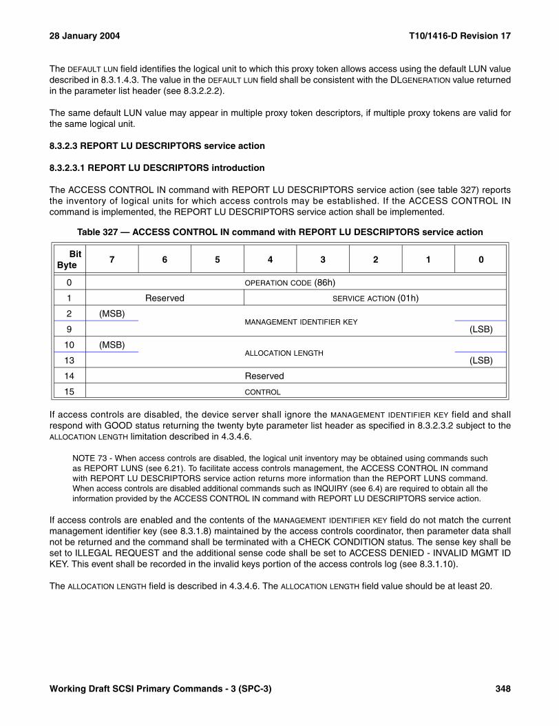
28 January 2004 T10/1416-D Revision 17
The DEFAULT LUN field identifies the logical unit to which this proxy token allows access using the default LUN valuedescribed in 8.3.1.4.3. The value in the DEFAULT LUN field shall be consistent with the DLGENERATION value returnedin the parameter list header (see 8.3.2.2.2).
The same default LUN value may appear in multiple proxy token descriptors, if multiple proxy tokens are valid forthe same logical unit.
8.3.2.3 REPORT LU DESCRIPTORS service action
8.3.2.3.1 REPORT LU DESCRIPTORS introduction
The ACCESS CONTROL IN command with REPORT LU DESCRIPTORS service action (see table 327) reportsthe inventory of logical units for which access controls may be established. If the ACCESS CONTROL INcommand is implemented, the REPORT LU DESCRIPTORS service action shall be implemented.
If access controls are disabled, the device server shall ignore the MANAGEMENT IDENTIFIER KEY field and shallrespond with GOOD status returning the twenty byte parameter list header as specified in 8.3.2.3.2 subject to theALLOCATION LENGTH limitation described in 4.3.4.6.
NOTE 73 - When access controls are disabled, the logical unit inventory may be obtained using commands suchas REPORT LUNS (see 6.21). To facilitate access controls management, the ACCESS CONTROL IN commandwith REPORT LU DESCRIPTORS service action returns more information than the REPORT LUNS command.When access controls are disabled additional commands such as INQUIRY (see 6.4) are required to obtain all theinformation provided by the ACCESS CONTROL IN command with REPORT LU DESCRIPTORS service action.
If access controls are enabled and the contents of the MANAGEMENT IDENTIFIER KEY field do not match the currentmanagement identifier key (see 8.3.1.8) maintained by the access controls coordinator, then parameter data shallnot be returned and the command shall be terminated with a CHECK CONDITION status. The sense key shall beset to ILLEGAL REQUEST and the additional sense code shall be set to ACCESS DENIED - INVALID MGMT IDKEY. This event shall be recorded in the invalid keys portion of the access controls log (see 8.3.1.10).
The ALLOCATION LENGTH field is described in 4.3.4.6. The ALLOCATION LENGTH field value should be at least 20.
Table 327 — ACCESS CONTROL IN command with REPORT LU DESCRIPTORS service action
BitByte
7 6 5 4 3 2 1 0
0 OPERATION CODE (86h)
1 Reserved SERVICE ACTION (01h)
2 (MSB)MANAGEMENT IDENTIFIER KEY
9 (LSB)
10 (MSB)ALLOCATION LENGTH
13 (LSB)
14 Reserved
15 CONTROL
Working Draft SCSI Primary Commands - 3 (SPC-3) 348

T10/1416-D Revision 17 28 January 2004
8.3.2.3.2 REPORT LU DESCRIPTORS parameter data format
The format of the parameter data returned in response to an ACCESS CONTROL IN command with REPORT LUDESCRIPTORS service actions is shown in table 328.
The LU INVENTORY LENGTH field shall contain a count of the number of bytes in the remaining parameter data. If theallocation length is too small to transfer all of the REPORT LU DESCRIPTORS parameter data, the LU inventorylength shall not be adjusted to reflect the truncation. If access controls are disabled, the LU INVENTORY LENGTH fieldshall be set to 16.
The NUMBER OF LOGICAL UNITS field shall contain a count of the number of logical units managed by the accesscontrols coordinator. The value in NUMBER OF LOGICAL UNITS field shall be the same as the number of Logical Unitdescriptors that follow in the parameter data.
Table 328 — ACCESS CONTROL IN with REPORT LU DESCRIPTORS parameter data format
BitByte
7 6 5 4 3 2 1 0
Parameter list header
0 (MSB)LU INVENTORY LENGTH (n-3)
3 (LSB)
4 (MSB)NUMBER OF LOGICAL UNITS
7 (LSB)
8SUPPORTED LUN MASK FORMAT
15
16 (MSB)DLGENERATION
19 (LSB)
Logical Unit descriptors
20Logical Unit descriptor 0
.
.
.
Logical Unit descriptor xn
349 Working Draft SCSI Primary Commands - 3 (SPC-3)
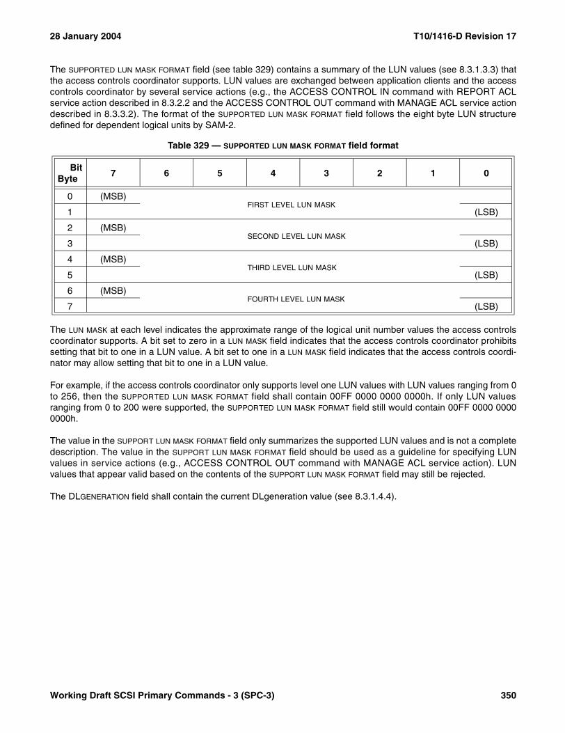
28 January 2004 T10/1416-D Revision 17
The SUPPORTED LUN MASK FORMAT field (see table 329) contains a summary of the LUN values (see 8.3.1.3.3) thatthe access controls coordinator supports. LUN values are exchanged between application clients and the accesscontrols coordinator by several service actions (e.g., the ACCESS CONTROL IN command with REPORT ACLservice action described in 8.3.2.2 and the ACCESS CONTROL OUT command with MANAGE ACL service actiondescribed in 8.3.3.2). The format of the SUPPORTED LUN MASK FORMAT field follows the eight byte LUN structuredefined for dependent logical units by SAM-2.
The LUN MASK at each level indicates the approximate range of the logical unit number values the access controlscoordinator supports. A bit set to zero in a LUN MASK field indicates that the access controls coordinator prohibitssetting that bit to one in a LUN value. A bit set to one in a LUN MASK field indicates that the access controls coordi-nator may allow setting that bit to one in a LUN value.
For example, if the access controls coordinator only supports level one LUN values with LUN values ranging from 0to 256, then the SUPPORTED LUN MASK FORMAT field shall contain 00FF 0000 0000 0000h. If only LUN valuesranging from 0 to 200 were supported, the SUPPORTED LUN MASK FORMAT field still would contain 00FF 0000 00000000h.
The value in the SUPPORT LUN MASK FORMAT field only summarizes the supported LUN values and is not a completedescription. The value in the SUPPORT LUN MASK FORMAT field should be used as a guideline for specifying LUNvalues in service actions (e.g., ACCESS CONTROL OUT command with MANAGE ACL service action). LUNvalues that appear valid based on the contents of the SUPPORT LUN MASK FORMAT field may still be rejected.
The DLGENERATION field shall contain the current DLgeneration value (see 8.3.1.4.4).
Table 329 — SUPPORTED LUN MASK FORMAT field format
BitByte
7 6 5 4 3 2 1 0
0 (MSB)FIRST LEVEL LUN MASK
1 (LSB)
2 (MSB)SECOND LEVEL LUN MASK
3 (LSB)
4 (MSB)THIRD LEVEL LUN MASK
5 (LSB)
6 (MSB)FOURTH LEVEL LUN MASK
7 (LSB)
Working Draft SCSI Primary Commands - 3 (SPC-3) 350
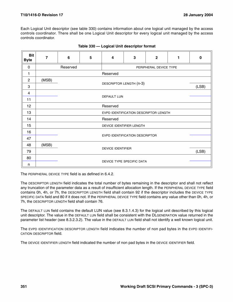
T10/1416-D Revision 17 28 January 2004
Each Logical Unit descriptor (see table 330) contains information about one logical unit managed by the accesscontrols coordinator. There shall be one Logical Unit descriptor for every logical unit managed by the accesscontrols coordinator.
The PERIPHERAL DEVICE TYPE field is as defined in 6.4.2.
The DESCRIPTOR LENGTH field indicates the total number of bytes remaining in the descriptor and shall not reflectany truncation of the parameter data as a result of insufficient allocation length. If the PERIPHERAL DEVICE TYPE fieldcontains 0h, 4h, or 7h, the DESCRIPTOR LENGTH field shall contain 92 if the descriptor includes the DEVICE TYPE
SPECIFIC DATA field and 80 if it does not. If the PERIPHERAL DEVICE TYPE field contains any value other than 0h, 4h, or7h, the DESCRIPTOR LENGTH field shall contain 76.
The DEFAULT LUN field contains the default LUN value (see 8.3.1.4.3) for the logical unit described by this logicalunit descriptor. The value in the DEFAULT LUN field shall be consistent with the DLGENERATION value returned in theparameter list header (see 8.3.2.3.2). The value in the DEFAULT LUN field shall not identify a well known logical unit.
The EVPD IDENTIFICATION DESCRIPTOR LENGTH field indicates the number of non pad bytes in the EVPD IDENTIFI-CATION DESCRIPTOR field.
The DEVICE IDENTIFIER LENGTH field indicated the number of non pad bytes in the DEVICE IDENTIFIER field.
Table 330 — Logical Unit descriptor format
BitByte
7 6 5 4 3 2 1 0
0 Reserved PERIPHERAL DEVICE TYPE
1 Reserved
2 (MSB)DESCRIPTOR LENGTH (n-3)
3 (LSB)
4DEFAULT LUN
11
12 Reserved
13 EVPD IDENTIFICATION DESCRIPTOR LENGTH
14 Reserved
15 DEVICE IDENTIFIER LENGTH
16EVPD IDENTIFICATION DESCRIPTOR
47
48 (MSB)DEVICE IDENTIFIER
79 (LSB)
80DEVICE TYPE SPECIFIC DATA
n
351 Working Draft SCSI Primary Commands - 3 (SPC-3)

28 January 2004 T10/1416-D Revision 17
The EVPD IDENTIFICATION DESCRIPTOR field shall be derived from one of the Device Identification VPD page (see7.6.4) identification descriptors having 0h in the ASSOCIATION field as follows:
a) If the identification descriptor has a length less than 32 bytes, then the EVPD IDENTIFICATION DESCRIPTOR field shall be set to the zero-padded (see 4.4.2) identification descriptor value. The EVPD IDENTIFICATION DESCRIPTOR LENGTH field shall be set to the length of the identification descriptor not including pad bytes; or
b) If the identification descriptor has a length greater than or equal to 32 bytes, then the EVPD IDENTIFICATION DESCRIPTOR field shall be set to the first 32 bytes of the identification descriptor. The EVPD IDENTIFICATION DESCRIPTOR LENGTH field shall be set to 32.
If there are several identification descriptors having 0h in the ASSOCIATION field, the choice of which descriptor tocopy to the EVPD IDENTIFICATION DESCRIPTOR field is vendor specific, however, all ACCESS CONTROL INcommands with REPORT LU DESCRIPTORS service action shall return the same EVPD IDENTIFICATION
DESCRIPTOR field contents for a specific logical unit.
If a device identifier has been set for the logical unit using the SET DEVICE IDENTIFIER command (see 6.27), theDEVICE IDENTIFIER field shall contain that device identifier subject to the following considerations:
a) If the device identifier has length less than 32 bytes, then the DEVICE IDENTIFIER field shall be set to the zero-padded (see 4.4.2) device identifier value. The DEVICE IDENTIFIER LENGTH field shall be set to the length of the device identifier not including pad bytes; or
b) If the device identifier has length greater than or equal to 32 bytes, then the DEVICE IDENTIFIER field shall be set to the first 32 bytes of the identifier The DEVICE IDENTIFIER LENGTH field shall be set to 32.
If no device identifier has been established by a SET DEVICE IDENTIFIER command, then the DEVICE IDENTIFIER
LENGTH field shall be set to zero and the DEVICE IDENTIFIER field shall be set to zero.
If the PERIPHERAL DEVICE TYPE field contains any value other than 0h, 4h, or 7h, the DEVICE TYPE SPECIFIC DATA fieldshall not be present in the Logical Unit descriptor.
The Logical Unit descriptor shall include the DEVICE TYPE SPECIFIC DATA field if:
a) The PERIPHERAL DEVICE TYPE field contains 0h, 4h, or 7h;b) The logical unit supports the READ CAPACITY command (see SBC-2) with:
A) The RELADR bit set to zero; andB) The PMI bit set to zero;and
c) The logical unit standard INQUIRY data (see 6.4.2) has the RMB bit set to zero.
If the Logical Unit descriptor includes the DEVICE TYPE SPECIFIC DATA field, then the size of the DEVICE TYPE SPECIFIC
DATA field shall be 12 bytes and the field shall contain the same data that would have been returned by asuccessful READ CAPACITY command with LONGLBA bit set to one, and the RELADR and PMI bits set to zero.
Working Draft SCSI Primary Commands - 3 (SPC-3) 352

T10/1416-D Revision 17 28 January 2004
8.3.2.4 REPORT ACCESS CONTROLS LOG service action
8.3.2.4.1 REPORT ACCESS CONTROLS LOG introduction
The ACCESS CONTROL IN command with REPORT ACCESS CONTROLS LOG service action (see table 331) isused to obtain the access controls log (see 8.3.1.10). If the ACCESS CONTROL IN command is implemented, theREPORT ACCESS CONTROLS LOG service action shall be implemented.
If access controls are disabled, the device server shall ignore the MANAGEMENT IDENTIFIER KEY field and shallrespond with GOOD status returning the eight byte parameter list header as specified in 8.3.2.4.2.1 subject to theALLOCATION LENGTH limitation described in 4.3.4.6.
Since the Key Overrides portion of the log is maintained while access controls are disabled (see 8.3.3.3), it may beretrieved by enabling access controls and issuing an ACCESS CONTROL IN command with REPORT ACCESSCONTROLS LOG service action.
If access controls are enabled and table 332 specifies that the management identifier key is not required then thedevice server shall ignore the contents of the MANAGEMENT IDENTIFIER KEY field.
If access controls are enabled, table 332 specifies that the management key identifier is required, and the contentsof the MANAGEMENT IDENTIFIER KEY field do not match the current management identifier key (see 8.3.1.8)maintained by the access controls coordinator, then the parameter data shall not be returned and the commandshall be terminated with a CHECK CONDITION status. The sense key shall be set to ILLEGAL REQUEST and theadditional sense code shall be set to ACCESS DENIED - INVALID MGMT ID KEY. This event shall be recorded inthe invalid keys portion of the access controls log (see 8.3.1.10).
Table 331 — ACCESS CONTROL IN command with REPORT ACCESS CONTROLS LOG service action
BitByte
7 6 5 4 3 2 1 0
0 OPERATION CODE (86h)
1 Reserved SERVICE ACTION (02h)
2 (MSB)MANAGEMENT IDENTIFIER KEY
9 (LSB)
10 Reserved LOG PORTION
11 Reserved
12 (MSB)ALLOCATION LENGTH
13 (LSB)
14 Reserved
15 CONTROL
353 Working Draft SCSI Primary Commands - 3 (SPC-3)

28 January 2004 T10/1416-D Revision 17
The LOG PORTION field (see table 332) specifies the access controls log portion being requested.
The ALLOCATION LENGTH field is described in 4.3.4.6. The ALLOCATION LENGTH field value should be at least eight.
8.3.2.4.2 REPORT ACCESS CONTROLS LOG parameter data format
8.3.2.4.2.1 REPORT ACCESS CONTROLS LOG parameter data introduction
The format of the parameter data returned in response to an ACCESS CONTROL IN command with REPORTACCESS CONTROLS LOG service actions is shown in table 333.
The LOG LIST LENGTH field shall contain a count of the number of bytes in the remaining parameter data. If theallocation length is too small to transfer all of the REPORT ACCESS CONTROLS LOG parameter data, the log listlength shall not be adjusted to reflect the truncation. If access controls are disabled, the LOG LIST LENGTH field shallbe set to four.
Table 332 — CDB LOG PORTION field values
Log Portion
Description Management Identifier Key Required
00b Key Overrides portion No01b Invalid Keys portion Yes10b ACL LUN Conflicts portion Yes11b Reserved
Table 333 — ACCESS CONTROL IN with REPORT ACCESS CONTROLS LOG parameter data format
BitByte
7 6 5 4 3 2 1 0
Parameter list header
0 (MSB)LOG LIST LENGTH (n-3)
3 (LSB)
4 Reserved
5 Reserved LOG PORTION
6 (MSB)COUNTER
7 (LSB)
Access Controls Log portion pages
8Access Controls Log portion page 0
.
.
.
Access Controls Log portion page xn
Working Draft SCSI Primary Commands - 3 (SPC-3) 354
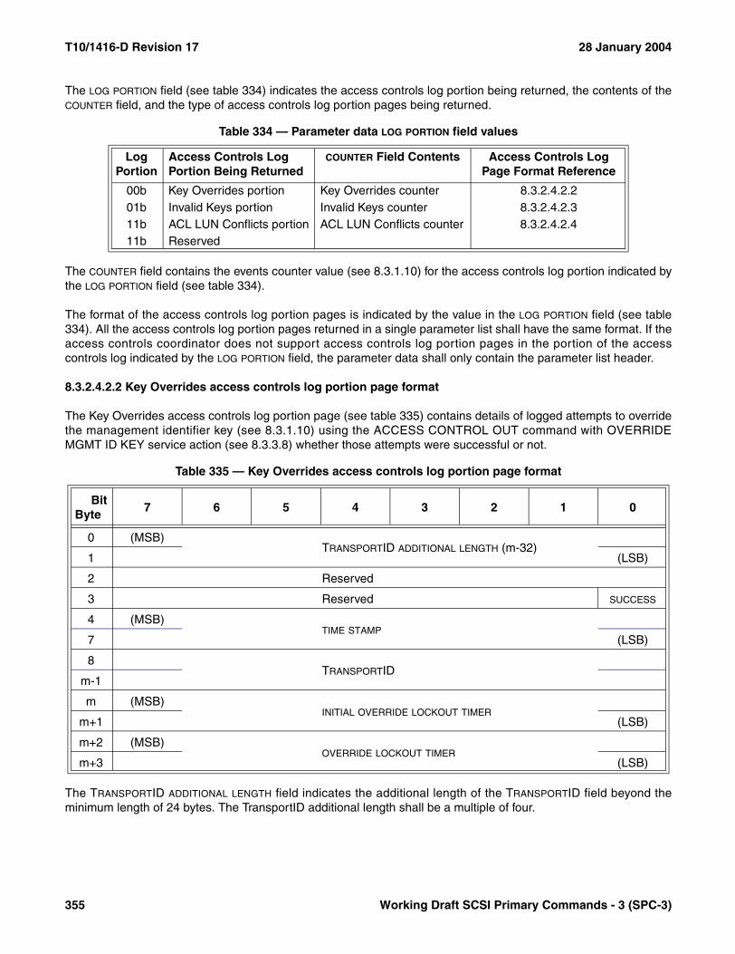
T10/1416-D Revision 17 28 January 2004
The LOG PORTION field (see table 334) indicates the access controls log portion being returned, the contents of theCOUNTER field, and the type of access controls log portion pages being returned.
The COUNTER field contains the events counter value (see 8.3.1.10) for the access controls log portion indicated bythe LOG PORTION field (see table 334).
The format of the access controls log portion pages is indicated by the value in the LOG PORTION field (see table334). All the access controls log portion pages returned in a single parameter list shall have the same format. If theaccess controls coordinator does not support access controls log portion pages in the portion of the accesscontrols log indicated by the LOG PORTION field, the parameter data shall only contain the parameter list header.
8.3.2.4.2.2 Key Overrides access controls log portion page format
The Key Overrides access controls log portion page (see table 335) contains details of logged attempts to overridethe management identifier key (see 8.3.1.10) using the ACCESS CONTROL OUT command with OVERRIDEMGMT ID KEY service action (see 8.3.3.8) whether those attempts were successful or not.
The TRANSPORTID ADDITIONAL LENGTH field indicates the additional length of the TRANSPORTID field beyond theminimum length of 24 bytes. The TransportID additional length shall be a multiple of four.
Table 334 — Parameter data LOG PORTION field values
Log Portion
Access Controls Log Portion Being Returned
COUNTER Field Contents Access Controls Log Page Format Reference
00b Key Overrides portion Key Overrides counter 8.3.2.4.2.201b Invalid Keys portion Invalid Keys counter 8.3.2.4.2.311b ACL LUN Conflicts portion ACL LUN Conflicts counter 8.3.2.4.2.411b Reserved
Table 335 — Key Overrides access controls log portion page format
BitByte
7 6 5 4 3 2 1 0
0 (MSB)TRANSPORTID ADDITIONAL LENGTH (m-32)
1 (LSB)
2 Reserved
3 Reserved SUCCESS
4 (MSB)TIME STAMP
7 (LSB)
8TRANSPORTID
m-1
m (MSB)INITIAL OVERRIDE LOCKOUT TIMER
m+1 (LSB)
m+2 (MSB)OVERRIDE LOCKOUT TIMER
m+3 (LSB)
355 Working Draft SCSI Primary Commands - 3 (SPC-3)

28 January 2004 T10/1416-D Revision 17
A SUCCESS bit set to one indicates that the specific ACCESS CONTROL OUT command with OVERRIDE MGMTID KEY service action event recorded in the access controls log successfully overrode the management identifierkey. A SUCCESS bit set to zero indicates that the command did not succeed.
The TIME STAMP field shall contain zero or an indication of the time at which the ACCESS CONTROL OUTcommand with OVERRIDE MGMT ID KEY service action was processed as described in 8.3.1.10.
The TRANSPORTID field shall contain the TransportID of the initiator port from which the command was received.
The INITIAL OVERRIDE LOCKOUT TIMER field shall contain the access controls coordinator’s initial override lockouttimer value (see 8.3.1.8.2.2) at the time when the key override was logged.
The OVERRIDE LOCKOUT TIMER field shall contain the access controls coordinator’s override lockout timer value (see8.3.1.8.2.2) at the time when the key override was logged.
8.3.2.4.2.3 Invalid Keys access controls log portion page format
The Invalid Keys access controls log portion page (see table 336) contains details of logged receipts of ACCESSCONTROL IN or ACCESS CONTROL OUT commands specifying an incorrect management identifier key (see8.3.1.10).
The TRANSPORTID ADDITIONAL LENGTH field indicates the additional length of the TRANSPORTID field beyond theminimum length of 24 bytes. The TransportID additional length shall be a multiple of four.
The OPERATION CODE and SERVICE ACTION fields shall be set to the respective values from the CDB of the accesscontrols command that specified the invalid management identifier key.
The TIME STAMP field shall contain zero or an indication of the time at which the ACCESS CONTROL IN orACCESS CONTROL OUT command was processed as described in 8.3.1.10.
The TRANSPORTID field shall contain the TransportID of the initiator port from which the command was received.
The INVALID MANAGEMENT IDENTIFIER KEY field shall be set to the value of the invalid management identifier keydetected by the access controls coordinator.
Table 336 — Invalid Keys access controls log portion page format
BitByte
7 6 5 4 3 2 1 0
0 (MSB)TRANSPORTID ADDITIONAL LENGTH (m-32)
1 (LSB)
3 OPERATION CODE
4 Reserved SERVICE ACTION
5 (MSB)TIME STAMP
7 (LSB)
8TRANSPORTID
m-1
m (MSB)INVALID MANAGEMENT IDENTIFIER KEY
m+7 (LSB)
Working Draft SCSI Primary Commands - 3 (SPC-3) 356
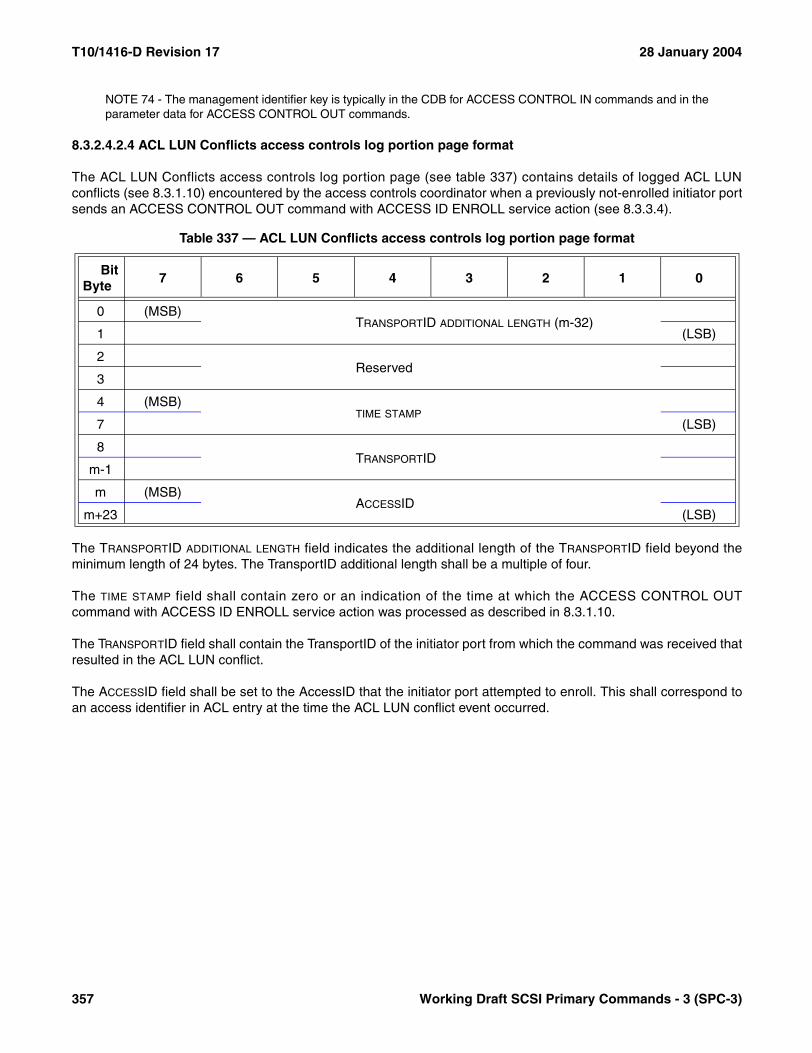
T10/1416-D Revision 17 28 January 2004
NOTE 74 - The management identifier key is typically in the CDB for ACCESS CONTROL IN commands and in theparameter data for ACCESS CONTROL OUT commands.
8.3.2.4.2.4 ACL LUN Conflicts access controls log portion page format
The ACL LUN Conflicts access controls log portion page (see table 337) contains details of logged ACL LUNconflicts (see 8.3.1.10) encountered by the access controls coordinator when a previously not-enrolled initiator portsends an ACCESS CONTROL OUT command with ACCESS ID ENROLL service action (see 8.3.3.4).
The TRANSPORTID ADDITIONAL LENGTH field indicates the additional length of the TRANSPORTID field beyond theminimum length of 24 bytes. The TransportID additional length shall be a multiple of four.
The TIME STAMP field shall contain zero or an indication of the time at which the ACCESS CONTROL OUTcommand with ACCESS ID ENROLL service action was processed as described in 8.3.1.10.
The TRANSPORTID field shall contain the TransportID of the initiator port from which the command was received thatresulted in the ACL LUN conflict.
The ACCESSID field shall be set to the AccessID that the initiator port attempted to enroll. This shall correspond toan access identifier in ACL entry at the time the ACL LUN conflict event occurred.
Table 337 — ACL LUN Conflicts access controls log portion page format
BitByte
7 6 5 4 3 2 1 0
0 (MSB)TRANSPORTID ADDITIONAL LENGTH (m-32)
1 (LSB)
2Reserved
3
4 (MSB)TIME STAMP
7 (LSB)
8TRANSPORTID
m-1
m (MSB)ACCESSID
m+23 (LSB)
357 Working Draft SCSI Primary Commands - 3 (SPC-3)
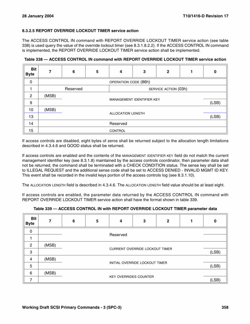
28 January 2004 T10/1416-D Revision 17
8.3.2.5 REPORT OVERRIDE LOCKOUT TIMER service action
The ACCESS CONTROL IN command with REPORT OVERRIDE LOCKOUT TIMER service action (see table338) is used query the value of the override lockout timer (see 8.3.1.8.2.2). If the ACCESS CONTROL IN commandis implemented, the REPORT OVERRIDE LOCKOUT TIMER service action shall be implemented.
If access controls are disabled, eight bytes of zeros shall be returned subject to the allocation length limitationsdescribed in 4.3.4.6 and GOOD status shall be returned.
If access controls are enabled and the contents of the MANAGEMENT IDENTIFIER KEY field do not match the currentmanagement identifier key (see 8.3.1.8) maintained by the access controls coordinator, then parameter data shallnot be returned, the command shall be terminated with a CHECK CONDITION status. The sense key shall be setto ILLEGAL REQUEST and the additional sense code shall be set to ACCESS DENIED - INVALID MGMT ID KEY.This event shall be recorded in the invalid keys portion of the access controls log (see 8.3.1.10).
The ALLOCATION LENGTH field is described in 4.3.4.6. The ALLOCATION LENGTH field value should be at least eight.
If access controls are enabled, the parameter data returned by the ACCESS CONTROL IN command withREPORT OVERRIDE LOCKOUT TIMER service action shall have the format shown in table 339.
Table 338 — ACCESS CONTROL IN command with REPORT OVERRIDE LOCKOUT TIMER service action
BitByte
7 6 5 4 3 2 1 0
0 OPERATION CODE (86h)
1 Reserved SERVICE ACTION (03h)
2 (MSB)MANAGEMENT IDENTIFIER KEY
9 (LSB)
10 (MSB)ALLOCATION LENGTH
13 (LSB)
14 Reserved
15 CONTROL
Table 339 — ACCESS CONTROL IN with REPORT OVERRIDE LOCKOUT TIMER parameter data
BitByte
7 6 5 4 3 2 1 0
0Reserved
1
2 (MSB)CURRENT OVERRIDE LOCKOUT TIMER
3 (LSB)
4 (MSB)INITIAL OVERRIDE LOCKOUT TIMER
5 (LSB)
6 (MSB)KEY OVERRIDES COUNTER
7 (LSB)
Working Draft SCSI Primary Commands - 3 (SPC-3) 358

T10/1416-D Revision 17 28 January 2004
The CURRENT OVERRIDE LOCKOUT TIMER field shall be set to the current value of the override lockout timer (see8.3.1.8.2.2).
The INITIAL OVERRIDE LOCKOUT TIMER field shall be set to the initial override lockout timer value (see 8.3.1.8.2.2)established by the last successful ACCESS CONTROL OUT command with MANAGE OVERRIDE LOCKOUTTIMER service action (see 8.3.3.7).
The KEY OVERRIDES COUNTER field shall be set to the value of the key overrides counter in the access controls log(see 8.3.1.10).
8.3.2.6 REQUEST PROXY TOKEN service action
The ACCESS CONTROL IN command with REQUEST PROXY TOKEN service action (see table 340) is used toobtain a proxy token (see 8.3.1.6.2) for a logical unit to which that initiator port has non-proxy access rights. Thereturned proxy token may be used to pass temporary access to the logical unit to a third party that may use otherproxy related service actions of the ACCESS CONTROL IN and ACCESS CONTROL OUT commands to gainaccess to the logical unit. If the ACCESS CONTROL IN command with REQUEST PROXY TOKEN service actionis not supported, the command shall be terminated with a CHECK CONDITION status, the sense key shall be setto ILLEGAL REQUEST and the additional sense code shall be set to INVALID FIELD IN CDB.
If access controls are disabled, the command shall be terminated with a CHECK CONDITION status, with thesense key set to ILLEGAL REQUEST and the additional sense code set to INVALID FIELD IN CDB.
NOTE 75 - If access controls are disabled, all logical units are accessible and all initiator ports share the same LUNvalues for addressing. A proxy token is not needed because sharing LUN values is sufficient.
The LUN VALUE field shall contain the LUN value the application client uses to access the logical unit via the initiatorport over which the proxy token is requested.
If the LUN value corresponds to a logical unit that is accessible to the requesting initiator port either through aTransportID or through the AccessID under which the initiator port is currently in the enrolled state (see 8.3.1.5.1),and the access controls coordinator has sufficient resources to create and manage a new proxy token, then theparameter data shown in table 341 shall be returned.
Table 340 — ACCESS CONTROL IN command with REQUEST PROXY TOKEN service action
BitByte
7 6 5 4 3 2 1 0
0 OPERATION CODE (86h)
1 Reserved SERVICE ACTION (04h)
2LUN VALUE
9
10 (MSB)ALLOCATION LENGTH
13 (LSB)
14 Reserved
15 CONTROL
359 Working Draft SCSI Primary Commands - 3 (SPC-3)

28 January 2004 T10/1416-D Revision 17
If the LUN value does not correspond to an accessible logical unit or corresponds to a logical unit accessible onlythrough a proxy token, then the parameter data shall not be returned and the command shall be terminated with aCHECK CONDITION status. The sense key shall be set to ILLEGAL REQUEST and the additional sense codeshall be set to ACCESS DENIED - INVALID LU IDENTIFIER.
If the LUN value corresponds to a logical unit accessible only through an enrolled AccessID and the initiator port isin the pending-enrolled state, then the parameter data shall not be returned and the command shall be terminatedwith a CHECK CONDITION status. The sense key shall be set to ILLEGAL REQUEST and the additional sensecode shall be set to ACCESS DENIED - INITIATOR PENDING-ENROLLED.
If the access controls coordinator does not have enough resources to create and manage a new proxy token, thecommand shall be terminated with a CHECK CONDITION status, the sense key shall be set to ILLEGALREQUEST and the additional sense code shall be set to INSUFFICIENT ACCESS CONTROL RESOURCES.
The ALLOCATION LENGTH field is described in 4.3.4.6. The ALLOCATION LENGTH field value should be at least eight.
The format of the parameter data returned by the ACCESS CONTROL IN command with REQUEST PROXYTOKEN service action is shown in table 341.
Table 341 — ACCESS CONTROL IN with REQUEST PROXY TOKEN parameter data
BitByte
7 6 5 4 3 2 1 0
0PROXY TOKEN
7
Working Draft SCSI Primary Commands - 3 (SPC-3) 360

T10/1416-D Revision 17 28 January 2004
8.3.3 ACCESS CONTROL OUT Command
8.3.3.1 ACCESS CONTROL OUT introduction
The service actions of the ACCESS CONTROL OUT command (see Table 25) are used to request service actionsby the access controls coordinator to limit or grant access to the logical units by initiator ports. If the ACCESSCONTROL OUT command is implemented, the ACCESS CONTROL IN command also shall be implemented. TheACCESS CONTROL OUT command shall not be affected by access controls.
The ACCESS CONTROL OUT command may be addressed to any logical unit whose standard INQUIRY data(see 6.4.2) has the ACC bit set to one (e.g., LUN 0), in which case it shall be processed in the same manner as ifthe command had been addressed to the ACCESS CONTROLS well known logical unit. If an ACCESS CONTROLOUT command is received by a device server whose standard INQUIRY data has the ACC bit set to zero, thecommand shall be terminated with a CHECK CONDITION status, the sense key shall be set to ILLEGALREQUEST and the additional sense code shall be set to INVALID COMMAND OPERATION CODE.
Table 342 — ACCESS CONTROL OUT service actions
Service Action Name Type Reference
00h MANAGE ACL M 8.3.3.201h DISABLE ACCESS CONTROLS M 8.3.3.302h ACCESS ID ENROLL M 8.3.3.403h CANCEL ENROLLMENT M 8.3.3.504h CLEAR ACCESS CONTROLS LOG M 8.3.3.605h MANAGE OVERRIDE LOCKOUT TIMER M 8.3.3.706h OVERRIDE MGMT ID KEY M 8.3.3.807h REVOKE PROXY TOKEN O 8.3.3.908h REVOKE ALL PROXY TOKENS O 8.3.3.1009h ASSIGN PROXY LUN O 8.3.3.110Ah RELEASE PROXY LUN O 8.3.3.12
0Bh - 17h Reserved18h - 1Fh Vendor specificKey: M = Service action implementation is mandatory if ACCESS CONTROL
OUT is implemented.O = Service action implementation is optional.
361 Working Draft SCSI Primary Commands - 3 (SPC-3)
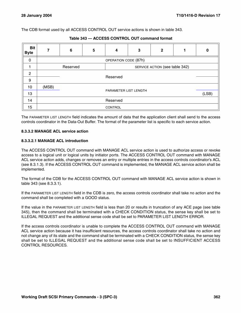
28 January 2004 T10/1416-D Revision 17
The CDB format used by all ACCESS CONTROL OUT service actions is shown in table 343.
The PARAMETER LIST LENGTH field indicates the amount of data that the application client shall send to the accesscontrols coordinator in the Data-Out Buffer. The format of the parameter list is specific to each service action.
8.3.3.2 MANAGE ACL service action
8.3.3.2.1 MANAGE ACL introduction
The ACCESS CONTROL OUT command with MANAGE ACL service action is used to authorize access or revokeaccess to a logical unit or logical units by initiator ports. The ACCESS CONTROL OUT command with MANAGEACL service action adds, changes or removes an entry or multiple entries in the access controls coordinator’s ACL(see 8.3.1.3). If the ACCESS CONTROL OUT command is implemented, the MANAGE ACL service action shall beimplemented.
The format of the CDB for the ACCESS CONTROL OUT command with MANAGE ACL service action is shown intable 343 (see 8.3.3.1).
If the PARAMETER LIST LENGTH field in the CDB is zero, the access controls coordinator shall take no action and thecommand shall be completed with a GOOD status.
If the value in the PARAMETER LIST LENGTH field is less than 20 or results in truncation of any ACE page (see table345), then the command shall be terminated with a CHECK CONDITION status, the sense key shall be set toILLEGAL REQUEST and the additional sense code shall be set to PARAMETER LIST LENGTH ERROR.
If the access controls coordinator is unable to complete the ACCESS CONTROL OUT command with MANAGEACL service action because it has insufficient resources, the access controls coordinator shall take no action andnot change any of its state and the command shall be terminated with a CHECK CONDITION status, the sense keyshall be set to ILLEGAL REQUEST and the additional sense code shall be set to INSUFFICIENT ACCESSCONTROL RESOURCES.
Table 343 — ACCESS CONTROL OUT command format
BitByte
7 6 5 4 3 2 1 0
0 OPERATION CODE (87h)
1 Reserved SERVICE ACTION (see table 342)
2Reserved
9
10 (MSB)PARAMETER LIST LENGTH
13 (LSB)
14 Reserved
15 CONTROL
Working Draft SCSI Primary Commands - 3 (SPC-3) 362
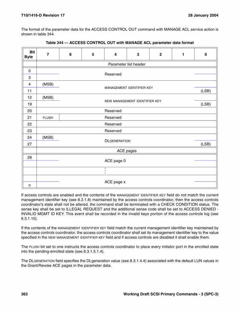
T10/1416-D Revision 17 28 January 2004
The format of the parameter data for the ACCESS CONTROL OUT command with MANAGE ACL service action isshown in table 344.
If access controls are enabled and the contents of the MANAGEMENT IDENTIFIER KEY field do not match the currentmanagement identifier key (see 8.3.1.8) maintained by the access controls coordinator, then the access controlscoordinator’s state shall not be altered, the command shall be terminated with a CHECK CONDITION status. Thesense key shall be set to ILLEGAL REQUEST and the additional sense code shall be set to ACCESS DENIED -INVALID MGMT ID KEY. This event shall be recorded in the invalid keys portion of the access controls log (see8.3.1.10).
If the contents of the MANAGEMENT IDENTIFIER KEY field match the current management identifier key maintained bythe access controls coordinator, the access controls coordinator shall set its management identifier key to the valuespecified in the NEW MANAGEMENT IDENTIFIER KEY field and if access controls are disabled it shall enable them.
The FLUSH bit set to one instructs the access controls coordinator to place every initiator port in the enrolled stateinto the pending-enrolled state (see 8.3.1.5.1.4).
The DLGENERATION field specifies the DLgeneration value (see 8.3.1.4.4) associated with the default LUN values inthe Grant/Revoke ACE pages in the parameter data.
Table 344 — ACCESS CONTROL OUT with MANAGE ACL parameter data format
BitByte
7 6 5 4 3 2 1 0
Parameter list header
0Reserved
3
4 (MSB)MANAGEMENT IDENTIFIER KEY
11 (LSB)
12 (MSB)NEW MANAGEMENT IDENTIFIER KEY
19 (LSB)
20 Reserved
21 FLUSH Reserved
22 Reserved
23 Reserved
24 (MSB)DLGENERATION
27 (LSB)
ACE pages
28ACE page 0
.
.
.
ACE page xn
363 Working Draft SCSI Primary Commands - 3 (SPC-3)

28 January 2004 T10/1416-D Revision 17
The ACE pages that may follow the parameter list header provide additional changes to the ACL. Each ACE pagedescribes one ACE in the ACL that is to be added, modified, or removed. The content and format of an ACE pageis indicated by a page code (see table 345).
The following requirements apply to the processing of changes to the access control state:
a) No change to the access control state shall occur if the ACCESS CONTROL OUT command with MANAGE ACL service action terminates with a status other than GOOD status; and
b) If the ACCESS CONTROL OUT command with MANAGE ACL service action completes with a GOOD status, the following shall have been performed as a single indivisible event:1) Changes resulting from the contents of fields in the parameter list header shall be processed; and2) Changes resulting from the contents of ACE pages shall be processed;
a) Multiple ACE pages shall be processed sequentially; b) If an ACE page contains conflicting instructions in LUACD descriptors, the instructions in the last
LUACD descriptor within the ACE page shall take precedence; andc) If an ACE containing an AccessID type access identifier (see 8.3.1.3.2) is replaced and the ACE
page that caused the change has the NOCNCL bit (see 8.3.3.2.2) set to zero, then any initiator port in the enrolled state or pending-enrolled state under the AccessID in that ACE shall be placed in the not-enrolled state (see 8.3.1.5.1.2).
An ACE page contains conflicting instructions if either of the following is true:
a) Two LUACD descriptors are present with the same LUN value and different default LUN values; or b) Two LUACD descriptors are present with different LUN values and the same default LUN value.
Table 345 — ACE page codes
Page Code ACE Page Name Reference
00h Grant/Revoke 8.3.3.2.201h Grant All 8.3.3.2.302h Revoke Proxy Token 8.3.3.2.403h Revoke All Proxy Tokens 8.3.3.2.5
04h-EFh ReservedF0h-FFh Vendor specific
Working Draft SCSI Primary Commands - 3 (SPC-3) 364
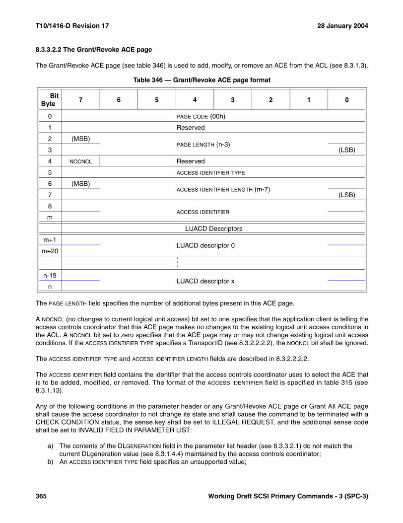
T10/1416-D Revision 17 28 January 2004
8.3.3.2.2 The Grant/Revoke ACE page
The Grant/Revoke ACE page (see table 346) is used to add, modify, or remove an ACE from the ACL (see 8.3.1.3).
The PAGE LENGTH field specifies the number of additional bytes present in this ACE page.
A NOCNCL (no changes to current logical unit access) bit set to one specifies that the application client is telling theaccess controls coordinator that this ACE page makes no changes to the existing logical unit access conditions inthe ACL. A NOCNCL bit set to zero specifies that the ACE page may or may not change existing logical unit accessconditions. If the ACCESS IDENTIFIER TYPE specifies a TransportID (see 8.3.2.2.2.2), the NOCNCL bit shall be ignored.
The ACCESS IDENTIFIER TYPE and ACCESS IDENTIFIER LENGTH fields are described in 8.3.2.2.2.2.
The ACCESS IDENTIFIER field contains the identifier that the access controls coordinator uses to select the ACE thatis to be added, modified, or removed. The format of the ACCESS IDENTIFIER field is specified in table 315 (see8.3.1.13).
Any of the following conditions in the parameter header or any Grant/Revoke ACE page or Grant All ACE pageshall cause the access coordinator to not change its state and shall cause the command to be terminated with aCHECK CONDITION status, the sense key shall be set to ILLEGAL REQUEST, and the additional sense codeshall be set to INVALID FIELD IN PARAMETER LIST:
a) The contents of the DLGENERATION field in the parameter list header (see 8.3.3.2.1) do not match the current DLgeneration value (see 8.3.1.4.4) maintained by the access controls coordinator;
b) An ACCESS IDENTIFIER TYPE field specifies an unsupported value;
Table 346 — Grant/Revoke ACE page format
BitByte
7 6 5 4 3 2 1 0
0 PAGE CODE (00h)
1 Reserved
2 (MSB)PAGE LENGTH (n-3)
3 (LSB)
4 NOCNCL Reserved
5 ACCESS IDENTIFIER TYPE
6 (MSB)ACCESS IDENTIFIER LENGTH (m-7)
7 (LSB)
8ACCESS IDENTIFIER
m
LUACD Descriptors
m+1LUACD descriptor 0
m+20...
n-19LUACD descriptor x
n
365 Working Draft SCSI Primary Commands - 3 (SPC-3)

28 January 2004 T10/1416-D Revision 17
c) An ACCESS IDENTIFIER TYPE field contains 01h (see 8.3.1.3.2) with an ACCESS IDENTIFIER field that contains an invalid TransportID (see 8.3.1.3.2) as defined for the applicable protocol standard;
d) Two ACE pages that have the same values in the ACCESS IDENTIFIER TYPE and ACCESS IDENTIFIER fields; ore) Changes in the ACL that result in an ACL LUN conflict (see 8.3.1.5.2).
NOTE 76 - The application client is responsible for obtaining the current association of default LUN values to logicalunits (and the DLgeneration value for that association) prior to issuing this service action. The ACCESS CONTROLIN command with REPORT LU DESCRIPTORS service action (see 8.3.2.3) returns the necessary information.
Each LUACD descriptor (see table 347) describes the access to be allowed to one logical unit based on the accessidentifier in the ACE page. An ACE page may contain zero or more LUACD descriptors.
The ACCESS MODE field is described in 8.3.2.2.2.2.
The LUN VALUE field specifies the LUN value an accessing application client uses to access the logical unit via theinitiator port to which the LUACD descriptor applies.
The DEFAULT LUN field specifies the logical unit to which the value in the LUN VALUE allows access. The DEFAULT LUN
field shall contain a default LUN value (see 8.3.1.4.3). The value in the DEFAULT LUN field shall be consistent withthe DLGENERATION field contents specified in the parameter list header (see 8.3.3.2.1). If the DEFAULT LUN fieldreferences a well known logical unit, the access controls coordinator’s state shall not be modified and thecommand shall be terminated with a CHECK CONDITION status, the sense key shall be set to ILLEGALREQUEST, and the additional sense code shall be set to INVALID FIELD IN PARAMETER LIST.
If the specified access mode is not supported or if the DEFAULT LUN field contains value that is not valid or the LUN
VALUE field contains a value that the access controls coordinator does not support as a valid LUN, the accesscontrols coordinator’s state shall not be modified and the command shall be terminated with a CHECKCONDITION status, the sense key shall be set to ILLEGAL REQUEST, the additional sense code shall be set toACCESS DENIED - INVALID LU IDENTIFIER, and the SENSE-KEY SPECIFIC field shall be set as described for theILLEGAL REQUEST sense key in 4.5.2.4.2. If the error is an unsupported value in the LUN VALUE field, the accesscontrols coordinator should determine a suggested LUN value that is unlikely to produce an error while alsominimizing the absolute value of the difference of the erroneous default LUN value and the suggested LUN value. Ifa suggested LUN value is determined, the first four bytes of the suggested LUN value shall be placed in the INFOR-MATION field and the last four bytes shall be placed in the COMMAND-SPECIFIC INFORMATION field of the sense data(see 4.5).
Table 347 — ACE page LUACD descriptor format
BitByte
7 6 5 4 3 2 1 0
0 ACCESS MODE
1Reserved
3
4LUN VALUE
11
12DEFAULT LUN
19
Working Draft SCSI Primary Commands - 3 (SPC-3) 366

T10/1416-D Revision 17 28 January 2004
Based on the access identifier and the presence or absence of LUACD descriptors, the access controls coordinatorshall add, modify, or remove an ACE in the ACL as shown in table 348.
If the ACCESS IDENTIFIER TYPE indicates type AccessID, the enrollment state (see 8.3.1.5.1) of any initiator port thatis enrolled under the specified AccessID, shall be affected as follows:
a) If the ACE containing the AccessID is removed, the initiator port shall be placed in the not-enrolled state; orb) If the ACE containing the AccessID is modified by a Grant/Revoke ACE page or a Grant All ACE page,
then;A) If the NOCNCL bit is set to zero in that ACE page, the initiator port shall be placed in the not-enrolled
state; orB) If the NOCNCL bit is set to in that ACE page, the enrollment state of the initiator port may be left
unchanged or the initiator port may be placed in the not-enrolled state (see 8.3.1.5.1.2) based on vendor specific considerations.
8.3.3.2.3 The Grant All ACE page
The Grant All ACE page (see table 349) is used to add or modify an ACE in the ACL (see 8.3.1.3). An ACE addedor modified using the Grant All ACE page allows initiator ports with the specified access identifier to access theSCSI target device as if access controls were disabled.
Table 348 — Access Coordinator Grant/Revoke ACE page actions
ACL already contains an ACE with the access identifier matching the one in the ACE page?
Yes No
ACE page includes LUCAD
descriptors?
YesModify the existing ACE in the ACL.
Add a new ACE to the ACL.
NoRemove the existing ACE from the ACL.
Take no action; this shall not be considered an error.
Table 349 — Grant All ACE page format
BitByte
7 6 5 4 3 2 1 0
0 PAGE CODE (01h)
1 Reserved
2 (MSB)PAGE LENGTH (n-3)
3 (LSB)
4 NOCNCL Reserved
5 ACCESS IDENTIFIER TYPE
6 (MSB)ACCESS IDENTIFIER LENGTH (m-7)
7 (LSB)
8ACCESS IDENTIFIER
n
367 Working Draft SCSI Primary Commands - 3 (SPC-3)

28 January 2004 T10/1416-D Revision 17
The PAGE LENGTH, NOCNCL, ACCESS IDENTIFIER TYPE, ACCESS IDENTIFIER LENGTH, and ACCESS IDENTIFIER fields aredefined in 8.3.3.2.2.
The Grant All ACE page shall be processed as if it is a Grant/Revoke ACE page (see 8.3.3.2.2) with one LUACDdescriptor for every logical unit managed by the access controls coordinator with the fields in each LUACDcontaining:
a) An access mode of 00h (see 8.3.2.2.2.2);b) A LUN VALUE field whose contents match the contents of the DEFAULT LUN field; andc) A DEFAULT LUN field whose contents reference the logical unit appropriate to the DLgeneration value (see
8.3.1.4.4).
8.3.3.2.4 The Revoke Proxy Token ACE page
The Revoke Proxy Token ACE page (see table 350) is used to revoke one or more proxy tokens (see 8.3.1.6.2).
The PAGE LENGTH field specifies the number of additional bytes present in this ACE page. If the page length is lessthan eight or not a multiple of eight, the command shall be terminated with a CHECK CONDITION status, thesense key shall be set to ILLEGAL REQUEST, and the additional sense code shall be set to PARAMETER LISTLENGTH ERROR.
The PROXY TOKEN field(s) specify the proxy tokens to be revoked. The access controls coordinator shall revokeeach proxy token listed in a PROXY TOKEN field. If the contents of a PROXY TOKEN field do not identify a valid proxytoken the field shall be ignored; this shall not be considered an error.
Multiple Revoke Proxy Token ACE pages may be included in the parameter data.
Table 350 — Revoke Proxy Token ACE page format
BitByte
7 6 5 4 3 2 1 0
0 PAGE CODE (02h)
1 Reserved
2 (MSB)PAGE LENGTH (n-3)
3 (LSB)
4PROXY TOKEN 0
11...
n-7PROXY TOKEN x
n
Working Draft SCSI Primary Commands - 3 (SPC-3) 368
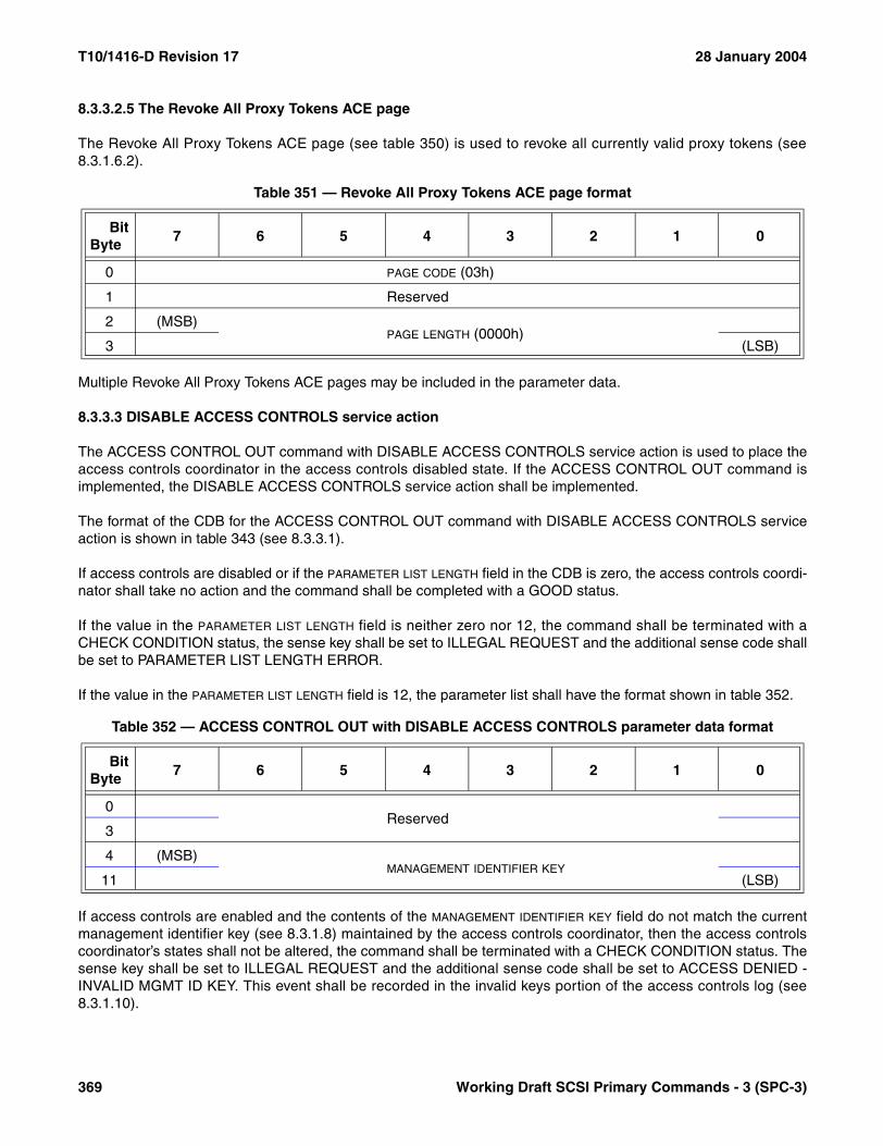
T10/1416-D Revision 17 28 January 2004
8.3.3.2.5 The Revoke All Proxy Tokens ACE page
The Revoke All Proxy Tokens ACE page (see table 350) is used to revoke all currently valid proxy tokens (see8.3.1.6.2).
Multiple Revoke All Proxy Tokens ACE pages may be included in the parameter data.
8.3.3.3 DISABLE ACCESS CONTROLS service action
The ACCESS CONTROL OUT command with DISABLE ACCESS CONTROLS service action is used to place theaccess controls coordinator in the access controls disabled state. If the ACCESS CONTROL OUT command isimplemented, the DISABLE ACCESS CONTROLS service action shall be implemented.
The format of the CDB for the ACCESS CONTROL OUT command with DISABLE ACCESS CONTROLS serviceaction is shown in table 343 (see 8.3.3.1).
If access controls are disabled or if the PARAMETER LIST LENGTH field in the CDB is zero, the access controls coordi-nator shall take no action and the command shall be completed with a GOOD status.
If the value in the PARAMETER LIST LENGTH field is neither zero nor 12, the command shall be terminated with aCHECK CONDITION status, the sense key shall be set to ILLEGAL REQUEST and the additional sense code shallbe set to PARAMETER LIST LENGTH ERROR.
If the value in the PARAMETER LIST LENGTH field is 12, the parameter list shall have the format shown in table 352.
If access controls are enabled and the contents of the MANAGEMENT IDENTIFIER KEY field do not match the currentmanagement identifier key (see 8.3.1.8) maintained by the access controls coordinator, then the access controlscoordinator’s states shall not be altered, the command shall be terminated with a CHECK CONDITION status. Thesense key shall be set to ILLEGAL REQUEST and the additional sense code shall be set to ACCESS DENIED -INVALID MGMT ID KEY. This event shall be recorded in the invalid keys portion of the access controls log (see8.3.1.10).
Table 351 — Revoke All Proxy Tokens ACE page format
BitByte
7 6 5 4 3 2 1 0
0 PAGE CODE (03h)
1 Reserved
2 (MSB)PAGE LENGTH (0000h)
3 (LSB)
Table 352 — ACCESS CONTROL OUT with DISABLE ACCESS CONTROLS parameter data format
BitByte
7 6 5 4 3 2 1 0
0Reserved
3
4 (MSB)MANAGEMENT IDENTIFIER KEY
11 (LSB)
369 Working Draft SCSI Primary Commands - 3 (SPC-3)

28 January 2004 T10/1416-D Revision 17
In response to an ACCESS CONTROL OUT command with DISABLE ACCESS CONTROLS service action withcorrect management identifier key value the access controls coordinator shall:
a) Disable access controls;b) Clear the ACL (see 8.3.1.3);c) Place all initiator ports into the not-enrolled state (see 8.3.1.5.1);d) Set the management identifier key to zero (see 8.3.1.8);e) Set the override lockout timer to zero (see 8.3.1.8.2.2);f) Set the initial override lockout timer value to zero (see 8.3.1.8.2.2);g) Clear the access controls log (including resetting counters to zero) with the exception of the key overrides
portion of the access controls log (see 8.3.1.10);h) Allow all initiator port’s access to all logical units at their default LUN value;i) Optionally, reset the DLgeneration value to zero (see 8.3.1.4.4); andj) Establish a unit attention condition for all initiator ports with an additional sense code of REPORTED LUNS
DATA HAS CHANGED.
8.3.3.4 ACCESS ID ENROLL service action
The ACCESS ID ENROLL service action of the ACCESS CONTROL OUT command is used by an applicationclient to enroll an AccessID for an initiator port with the access controls coordinator. If the ACCESS CONTROLOUT command is implemented, the ACCESS ID ENROLL service action shall be implemented.
The format of the CDB for the ACCESS CONTROL OUT command with ACCESS ID ENROLL service action isshown in table 343 (see 8.3.3.1).
If access controls are disabled or if the PARAMETER LIST LENGTH field in the CDB is zero, the access controls coordi-nator shall take no action and the command shall be completed with a GOOD status.
If the value in the PARAMETER LIST LENGTH field is neither zero nor 24, the command shall be terminated with aCHECK CONDITION status, the sense key shall be set to ILLEGAL REQUEST and the additional sense code shallbe set to PARAMETER LIST LENGTH ERROR.
If the value in the PARAMETER LIST LENGTH field is 24, the parameter list shall have the format shown in table 353.
The ACCESSID field is described in 8.3.1.3.2.
If the initiator port is in the enrolled state or pending-enrolled state (see 8.3.1.5.1) under a specific AccessID andthe ACCESSID field contains a different AccessID, the access controls coordinator shall place the initiator port in thepending-enrolled state, the command shall be terminated with a CHECK CONDITION status, the sense key shallbe set to ILLEGAL REQUEST and the additional sense code shall be set to ACCESS DENIED - ENROLLMENTCONFLICT.
Table 353 — ACCESS CONTROL OUT with ACCESS ID ENROLL parameter data format
BitByte
7 6 5 4 3 2 1 0
0ACCESSID
15
16Reserved
23
Working Draft SCSI Primary Commands - 3 (SPC-3) 370

T10/1416-D Revision 17 28 January 2004
If the initiator port is in the enrolled state or pending-enrolled state under a specific AccessID and the ACCESSIDfield contains a matching AccessID, the access controls coordinator shall place the initiator port in the enrolledstate and make no other changes.
If the initiator port is in the not-enrolled state and the ACCESSID field contents do not match the AccessID in anyACE in the ACL (see 8.3.1.3), the initiator port shall remain in the not-enrolled state and the command shall beterminated with a CHECK CONDITION status, the sense key shall be set to ILLEGAL REQUEST and theadditional sense code shall be set to ACCESS DENIED - NO ACCESS RIGHTS.
If the initiator port is in the not-enrolled state and the ACCESSID field contents matches the AccessID in an ACE inthe ACL the actions taken depend on whether enrolling the initiator port would create an ACL LUN conflict (see8.3.1.5.2). If there is no ACL LUN conflict, the initiator port shall be placed in the enrolled state (see 8.3.1.5.1.3). Ifthere is an ACL LUN conflict, then the initiator port shall remain in the not-enrolled state and the command shall beterminated with a CHECK CONDITION status. The sense key shall be set to ILLEGAL REQUEST and theadditional sense code shall be set to ACCESS DENIED - ACL LUN CONFLICT. This event shall be recorded in theACL LUN conflicts portion of the access controls log (see 8.3.1.10).
An application client that receives the ACCESS DENIED - ACL LUN CONFLICT additional sense code shouldremove any proxy access rights it has acquired using the ACCESS CONTROL OUT command with RELEASEPROXY LUN service action and retry the enrollment request. If the ACL LUN conflict resulted from proxy access,the retried enrollment succeeds. Otherwise, the mechanisms for resolving ACL LUN conflicts are outside the scopeof this standard.
8.3.3.5 CANCEL ENROLLMENT service action
The ACCESS CONTROL OUT command with CANCEL ENROLLMENT service action is used to remove aninitiator port’s enrollment with the access controls coordinator (see 8.3.1.5). Successful completion of thiscommand changes the state of the initiator port to the not-enrolled state. If the ACCESS CONTROL OUTcommand is implemented, the CANCEL ENROLLMENT service action shall be implemented.
The ACCESS CONTROL OUT command with CANCEL ENROLLMENT service action should be used by an appli-cation client prior to any period where use of its accessible logical units may be suspended for a lengthy period oftime (e.g., when a host is preparing to shutdown). This allows the access controls coordinator to free any resourcesallocated to manage the enrollment for the initiator port.
The format of the CDB for the ACCESS CONTROL OUT command with ACCESS ID ENROLL service action isshown in table 343 (see 8.3.3.1).
If access controls are disabled, the access controls coordinator shall take no action and the command shall becompleted with a GOOD status.
There is no parameter data for the ACCESS CONTROL OUT command with CANCEL ENROLLMENT serviceaction. If the PARAMETER LIST LENGTH field in the CDB is not set to zero, the initiator port’s enrollment shall not bechanged and the command shall be terminated with a CHECK CONDITION status, the sense key shall be set toILLEGAL REQUEST and the additional sense code shall be set to PARAMETER LIST LENGTH ERROR.
If the PARAMETER LIST LENGTH field in the CDB is set to zero, the initiator port shall be placed in the not-enrolledstate (see 8.3.1.5.1.2) Any subsequent commands addressed to the logical units no longer accessible are handledaccording to the requirements stated in 8.3.1.7.
371 Working Draft SCSI Primary Commands - 3 (SPC-3)
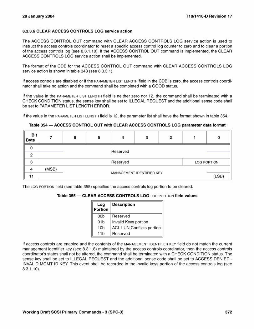
28 January 2004 T10/1416-D Revision 17
8.3.3.6 CLEAR ACCESS CONTROLS LOG service action
The ACCESS CONTROL OUT command with CLEAR ACCESS CONTROLS LOG service action is used toinstruct the access controls coordinator to reset a specific access control log counter to zero and to clear a portionof the access controls log (see 8.3.1.10). If the ACCESS CONTROL OUT command is implemented, the CLEARACCESS CONTROLS LOG service action shall be implemented.
The format of the CDB for the ACCESS CONTROL OUT command with CLEAR ACCESS CONTROLS LOGservice action is shown in table 343 (see 8.3.3.1).
If access controls are disabled or if the PARAMETER LIST LENGTH field in the CDB is zero, the access controls coordi-nator shall take no action and the command shall be completed with a GOOD status.
If the value in the PARAMETER LIST LENGTH field is neither zero nor 12, the command shall be terminated with aCHECK CONDITION status, the sense key shall be set to ILLEGAL REQUEST and the additional sense code shallbe set to PARAMETER LIST LENGTH ERROR.
If the value in the PARAMETER LIST LENGTH field is 12, the parameter list shall have the format shown in table 354.
The LOG PORTION field (see table 355) specifies the access controls log portion to be cleared.
If access controls are enabled and the contents of the MANAGEMENT IDENTIFIER KEY field do not match the currentmanagement identifier key (see 8.3.1.8) maintained by the access controls coordinator, then the access controlscoordinator’s states shall not be altered, the command shall be terminated with a CHECK CONDITION status. Thesense key shall be set to ILLEGAL REQUEST and the additional sense code shall be set to ACCESS DENIED -INVALID MGMT ID KEY. This event shall be recorded in the invalid keys portion of the access controls log (see8.3.1.10).
Table 354 — ACCESS CONTROL OUT with CLEAR ACCESS CONTROLS LOG parameter data format
BitByte
7 6 5 4 3 2 1 0
0Reserved
2
3 Reserved LOG PORTION
4 (MSB)MANAGEMENT IDENTIFIER KEY
11 (LSB)
Table 355 — CLEAR ACCESS CONTROLS LOG LOG PORTION field values
Log Portion
Description
00b Reserved01b Invalid Keys portion10b ACL LUN Conflicts portion11b Reserved
Working Draft SCSI Primary Commands - 3 (SPC-3) 372
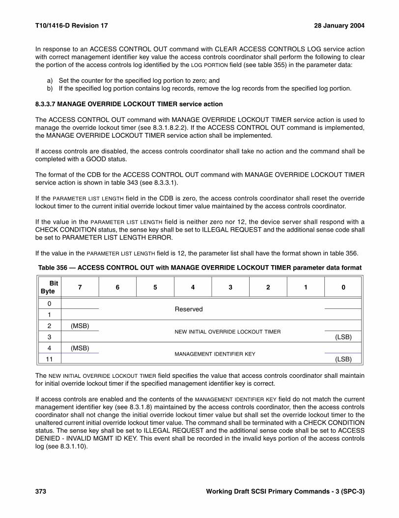
T10/1416-D Revision 17 28 January 2004
In response to an ACCESS CONTROL OUT command with CLEAR ACCESS CONTROLS LOG service actionwith correct management identifier key value the access controls coordinator shall perform the following to clearthe portion of the access controls log identified by the LOG PORTION field (see table 355) in the parameter data:
a) Set the counter for the specified log portion to zero; andb) If the specified log portion contains log records, remove the log records from the specified log portion.
8.3.3.7 MANAGE OVERRIDE LOCKOUT TIMER service action
The ACCESS CONTROL OUT command with MANAGE OVERRIDE LOCKOUT TIMER service action is used tomanage the override lockout timer (see 8.3.1.8.2.2). If the ACCESS CONTROL OUT command is implemented,the MANAGE OVERRIDE LOCKOUT TIMER service action shall be implemented.
If access controls are disabled, the access controls coordinator shall take no action and the command shall becompleted with a GOOD status.
The format of the CDB for the ACCESS CONTROL OUT command with MANAGE OVERRIDE LOCKOUT TIMERservice action is shown in table 343 (see 8.3.3.1).
If the PARAMETER LIST LENGTH field in the CDB is zero, the access controls coordinator shall reset the overridelockout timer to the current initial override lockout timer value maintained by the access controls coordinator.
If the value in the PARAMETER LIST LENGTH field is neither zero nor 12, the device server shall respond with aCHECK CONDITION status, the sense key shall be set to ILLEGAL REQUEST and the additional sense code shallbe set to PARAMETER LIST LENGTH ERROR.
If the value in the PARAMETER LIST LENGTH field is 12, the parameter list shall have the format shown in table 356.
The NEW INITIAL OVERRIDE LOCKOUT TIMER field specifies the value that access controls coordinator shall maintainfor initial override lockout timer if the specified management identifier key is correct.
If access controls are enabled and the contents of the MANAGEMENT IDENTIFIER KEY field do not match the currentmanagement identifier key (see 8.3.1.8) maintained by the access controls coordinator, then the access controlscoordinator shall not change the initial override lockout timer value but shall set the override lockout timer to theunaltered current initial override lockout timer value. The command shall be terminated with a CHECK CONDITIONstatus. The sense key shall be set to ILLEGAL REQUEST and the additional sense code shall be set to ACCESSDENIED - INVALID MGMT ID KEY. This event shall be recorded in the invalid keys portion of the access controlslog (see 8.3.1.10).
Table 356 — ACCESS CONTROL OUT with MANAGE OVERRIDE LOCKOUT TIMER parameter data format
BitByte
7 6 5 4 3 2 1 0
0Reserved
1
2 (MSB)NEW INITIAL OVERRIDE LOCKOUT TIMER
3 (LSB)
4 (MSB)MANAGEMENT IDENTIFIER KEY
11 (LSB)
373 Working Draft SCSI Primary Commands - 3 (SPC-3)

28 January 2004 T10/1416-D Revision 17
In response to an ACCESS CONTROL OUT command with MANAGE OVERRIDE LOCKOUT TIMER serviceaction with correct management identifier key value the access controls coordinator shall:
a) Replace the currently saved initial override lockout timer with the value in the NEW INITIAL OVERRIDE LOCKOUT TIMER field; and
b) Set the override lockout timer to the new initial value.
8.3.3.8 OVERRIDE MGMT ID KEY service action
The ACCESS CONTROL OUT command with OVERRIDE MGMT ID KEY service action is used to override thecurrent management identifier key (see 8.3.1.4.2) maintained by the access controls coordinator. The ACCESSCONTROL OUT command with OVERRIDE MGMT ID KEY service action should be used in a failure situationwhere the application client no longer has access to its copy of the current management identifier key.
Successful use of the ACCESS CONTROL OUT command with OVERRIDE MGMT ID KEY service action isrestricted by the override lockout timer (see 8.3.1.8.2.2).
If the ACCESS CONTROL OUT command is implemented, the OVERRIDE MGMT ID KEY service action shall beimplemented.
The format of the CDB for the ACCESS CONTROL OUT command with OVERRIDE MGMT ID KEY service actionis shown in table 343 (see 8.3.3.1).
If access controls are disabled or if the PARAMETER LIST LENGTH field in the CDB is zero, the access controls coordi-nator shall take no action and the command shall be completed with a GOOD status.
If access controls are enabled, the access controls coordinator shall log every ACCESS CONTROL OUTcommand with OVERRIDE MGMT ID KEY service action processed whether successful or not in the accesscontrols log as specified in 8.3.1.10.
If the value in the PARAMETER LIST LENGTH field is neither zero nor 12, the command shall be terminated with aCHECK CONDITION status, the sense key shall be set to ILLEGAL REQUEST and the additional sense code shallbe set to PARAMETER LIST LENGTH ERROR.
If the value in the PARAMETER LIST LENGTH field is 12, the parameter data shall have the format shown in table 357.
The NEW MANAGEMENT IDENTIFIER KEY field specifies a new management identifier key.
If the override lockout timer managed by the access controls coordinator is not zero, the access controls coordi-nator’s states shall not be altered, the command shall be terminated with a CHECK CONDITION status, the sensekey shall be set to ILLEGAL REQUEST and the additional sense code shall be set to INVALID FIELD IN CDB.
Table 357 — ACCESS CONTROL OUT with OVERRIDE MGMT ID KEY parameter data format
BitByte
7 6 5 4 3 2 1 0
0Reserved
3
4 (MSB)NEW MANAGEMENT IDENTIFIER KEY
11 (LSB)
Working Draft SCSI Primary Commands - 3 (SPC-3) 374

T10/1416-D Revision 17 28 January 2004
If the override lockout timer managed by the access controls coordinator is zero, then the access controls coordi-nator shall replace the current management identifier key with the value in the to the NEW MANAGEMENT IDENTIFIER
KEY field.
8.3.3.9 REVOKE PROXY TOKEN service action
An application client for an initiator port uses the ACCESS CONTROL OUT command with REVOKE PROXYTOKEN service action to cancel all proxy access rights to a logical unit that have been granted under the specifiedproxy token (see 8.3.1.6.2). If this service action is not supported, the command shall be terminated with a CHECKCONDITION status, the sense key shall be set to ILLEGAL REQUEST and the additional sense code shall be setto INVALID FIELD IN CDB.
The format of the CDB for the ACCESS CONTROL OUT command with REVOKE PROXY TOKEN service actionis shown in table 343 (see 8.3.3.1).
If access controls are disabled or if the PARAMETER LIST LENGTH field in the CDB is zero, the access controls coordi-nator shall take no action and the command shall be completed with a GOOD status.
If the value in the PARAMETER LIST LENGTH field is neither zero nor eight, the command shall be terminated with aCHECK CONDITION status, the sense key shall be set to ILLEGAL REQUEST and the additional sense code shallbe set to PARAMETER LIST LENGTH ERROR.
If the value in the PARAMETER LIST LENGTH field is eight, the parameter data shall have the format shown in table358.
If the PROXY TOKEN field does not contain a valid proxy token previously obtained via the initiator port, no action istaken by the access controls coordinator. This shall not be considered an error.
If the proxy token is valid, the access controls coordinator shall take the following actions:
a) Invalidate the proxy token; andb) Deny access to the associated logical unit by any initiator port whose rights were granted under that proxy
token via an ACCESS CONTROL OUT command with ASSIGN PROXY LUN service action (see 8.3.3.11) according to the requirements stated in 8.3.1.7.
8.3.3.10 REVOKE ALL PROXY TOKENS service action
An application client for an initiator port uses the ACCESS CONTROL OUT command with REVOKE ALL PROXYTOKENS service action to cancel all proxy access rights to a specified logical unit that it obtained with zero or moreproxy tokens (see 8.3.1.6.2). If this service action is not supported, the command shall be terminated with aCHECK CONDITION status, the sense key shall be set to ILLEGAL REQUEST and the additional sense code shallbe set to INVALID FIELD IN CDB.
The format of the CDB for the ACCESS CONTROL OUT command with REVOKE ALL PROXY TOKENS serviceaction is shown in table 343 (see 8.3.3.1).
Table 358 — ACCESS CONTROL OUT with REVOKE PROXY TOKEN parameter data format
BitByte
7 6 5 4 3 2 1 0
0PROXY TOKEN
7
375 Working Draft SCSI Primary Commands - 3 (SPC-3)
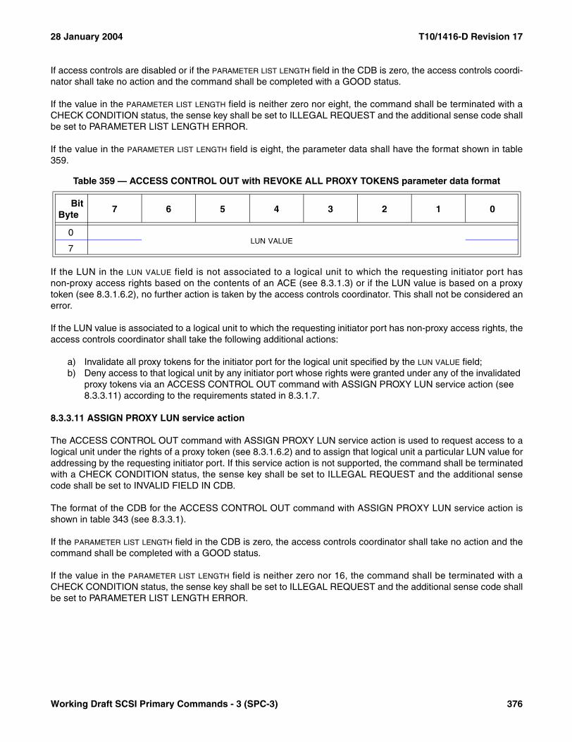
28 January 2004 T10/1416-D Revision 17
If access controls are disabled or if the PARAMETER LIST LENGTH field in the CDB is zero, the access controls coordi-nator shall take no action and the command shall be completed with a GOOD status.
If the value in the PARAMETER LIST LENGTH field is neither zero nor eight, the command shall be terminated with aCHECK CONDITION status, the sense key shall be set to ILLEGAL REQUEST and the additional sense code shallbe set to PARAMETER LIST LENGTH ERROR.
If the value in the PARAMETER LIST LENGTH field is eight, the parameter data shall have the format shown in table359.
If the LUN in the LUN VALUE field is not associated to a logical unit to which the requesting initiator port hasnon-proxy access rights based on the contents of an ACE (see 8.3.1.3) or if the LUN value is based on a proxytoken (see 8.3.1.6.2), no further action is taken by the access controls coordinator. This shall not be considered anerror.
If the LUN value is associated to a logical unit to which the requesting initiator port has non-proxy access rights, theaccess controls coordinator shall take the following additional actions:
a) Invalidate all proxy tokens for the initiator port for the logical unit specified by the LUN VALUE field;b) Deny access to that logical unit by any initiator port whose rights were granted under any of the invalidated
proxy tokens via an ACCESS CONTROL OUT command with ASSIGN PROXY LUN service action (see 8.3.3.11) according to the requirements stated in 8.3.1.7.
8.3.3.11 ASSIGN PROXY LUN service action
The ACCESS CONTROL OUT command with ASSIGN PROXY LUN service action is used to request access to alogical unit under the rights of a proxy token (see 8.3.1.6.2) and to assign that logical unit a particular LUN value foraddressing by the requesting initiator port. If this service action is not supported, the command shall be terminatedwith a CHECK CONDITION status, the sense key shall be set to ILLEGAL REQUEST and the additional sensecode shall be set to INVALID FIELD IN CDB.
The format of the CDB for the ACCESS CONTROL OUT command with ASSIGN PROXY LUN service action isshown in table 343 (see 8.3.3.1).
If the PARAMETER LIST LENGTH field in the CDB is zero, the access controls coordinator shall take no action and thecommand shall be completed with a GOOD status.
If the value in the PARAMETER LIST LENGTH field is neither zero nor 16, the command shall be terminated with aCHECK CONDITION status, the sense key shall be set to ILLEGAL REQUEST and the additional sense code shallbe set to PARAMETER LIST LENGTH ERROR.
Table 359 — ACCESS CONTROL OUT with REVOKE ALL PROXY TOKENS parameter data format
BitByte
7 6 5 4 3 2 1 0
0LUN VALUE
7
Working Draft SCSI Primary Commands - 3 (SPC-3) 376
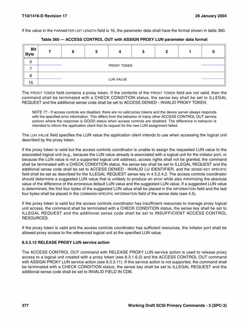
T10/1416-D Revision 17 28 January 2004
If the value in the PARAMETER LIST LENGTH field is 16, the parameter data shall have the format shown in table 360.
The PROXY TOKEN field contains a proxy token. If the contents of the PROXY TOKEN field are not valid, then thecommand shall be terminated with a CHECK CONDITION status, the sense key shall be set to ILLEGALREQUEST and the additional sense code shall be set to ACCESS DENIED - INVALID PROXY TOKEN.
NOTE 77 - If access controls are disabled, there are no valid proxy tokens and the device server always respondswith the specified error information. This differs from the behavior of many other ACCESS CONTROL OUT serviceactions where the response is GOOD status when access controls are disabled. The difference in behavior isintended to inform the application client that its request for the new LUN assignment failed.
The LUN VALUE field specifies the LUN value the application client intends to use when accessing the logical unitdescribed by the proxy token.
If the proxy token is valid but the access controls coordinator is unable to assign the requested LUN value to theassociated logical unit (e.g., because the LUN value already is associated with a logical unit for the initiator port, orbecause the LUN value is not a supported logical unit address), access rights shall not be granted, the commandshall be terminated with a CHECK CONDITION status, the sense key shall be set to ILLEGAL REQUEST and theadditional sense code shall be set to ACCESS DENIED - INVALID LU IDENTIFIER, and the SENSE-KEY SPECIFIC
field shall be set as described for the ILLEGAL REQUEST sense key in 4.5.2.4.2. The access controls coordinatorshould determine a suggested LUN value that is unlikely to produce an error while also minimizing the absolutevalue of the difference of the erroneous default LUN value and the suggested LUN value. If a suggested LUN valueis determined, the first four bytes of the suggested LUN value shall be placed in the INFORMATION field and the lastfour bytes shall be placed in the COMMAND-SPECIFIC INFORMATION field of the sense data (see 4.5).
If the proxy token is valid but the access controls coordinator has insufficient resources to manage proxy logicalunit access, the command shall be terminated with a CHECK CONDITION status, the sense key shall be set toILLEGAL REQUEST and the additional sense code shall be set to INSUFFICIENT ACCESS CONTROLRESOURCES.
If the proxy token is valid and the access controls coordinator has sufficient resources, the initiator port shall beallowed proxy access to the referenced logical unit at the specified LUN value.
8.3.3.12 RELEASE PROXY LUN service action
The ACCESS CONTROL OUT command with RELEASE PROXY LUN service action is used to release proxyaccess to a logical unit created with a proxy token (see 8.3.1.6.2) and the ACCESS CONTROL OUT commandwith ASSIGN PROXY LUN service action (see 8.3.3.11). If this service action is not supported, the command shallbe terminated with a CHECK CONDITION status, the sense key shall be set to ILLEGAL REQUEST and theadditional sense code shall be set to INVALID FIELD IN CDB.
Table 360 — ACCESS CONTROL OUT with ASSIGN PROXY LUN parameter data format
BitByte
7 6 5 4 3 2 1 0
0PROXY TOKEN
7
8LUN VALUE
15
377 Working Draft SCSI Primary Commands - 3 (SPC-3)

28 January 2004 T10/1416-D Revision 17
The ACCESS CONTROL OUT command with RELEASE PROXY LUN service action should be used when anapplication client no longer requires the logical unit access rights granted to an initiator port under a proxy token(e.g., when a copy manager has completed a specific third party copy operation under a proxy token). This allowsthe access controls coordinator to free any resources allocated to manage the proxy access.
The format of the CDB for the ACCESS CONTROL OUT command with RELEASE PROXY LUN service action isshown in table 343 (see 8.3.3.1).
If the PARAMETER LIST LENGTH field in the CDB is zero, the access controls coordinator shall take no action and thecommand shall be completed with a GOOD status.
If the value in the PARAMETER LIST LENGTH field is neither zero nor eight, the command shall be terminated with aCHECK CONDITION status, the sense key shall be set to ILLEGAL REQUEST and the additional sense code shallbe set to PARAMETER LIST LENGTH ERROR.
If the value in the PARAMETER LIST LENGTH field is eight, the parameter data shall have the format shown in table361.
The LUN VALUE field specifies a LUN value that was associated with a logical unit based on a proxy token using anACCESS CONTROL OUT command with ASSIGN PROXY LUN service action. If the LUN value was not assignedto a logical unit by an ACCESS CONTROL OUT command with ASSIGN PROXY LUN service action, thecommand shall be terminated with a CHECK CONDITION status, the sense key shall be set to ILLEGALREQUEST and the additional sense code shall be set to INVALID FIELD IN PARAMETER LIST.
NOTE 78 - If access controls are disabled, there are no valid proxy tokens and therefore no LUN value could beassigned to a logical unit by an ACCESS CONTROL OUT command with ASSIGN PROXY LUN service action sothe device server always responds with the specified error information. This differs from the behavior of many otherACCESS CONTROL OUT service actions where the response is GOOD status when access controls are disabled.The difference in behavior is intended to inform the application client that the LUN value remains as a valid addressfor the logical unit.
If the LUN value was assigned to a logical unit by an ACCESS CONTROL OUT command with ASSIGN PROXYLUN service action, the access controls coordinator shall not allow access to the logical unit at the specified LUNvalue.
Table 361 — ACCESS CONTROL OUT with RELEASE PROXY LUN parameter data format
BitByte
7 6 5 4 3 2 1 0
0LUN VALUE
7
Working Draft SCSI Primary Commands - 3 (SPC-3) 378

T10/1416-D Revision 17 28 January 2004
8.4 TARGET LOG PAGES well known logical unit
The TARGET LOG PAGES well known logical unit shall only process the commands listed in table 362. If acommand is received by the TARGET LOG PAGES well know logical unit that is not listed in table 362 the deviceserver shall return CHECK CONDITION status with the sense key set to ILLEGAL REQUEST and an additionalsense code of INVALID COMMAND OPERATION CODE.
The TARGET LOG PAGES well known logical unit shall support the Protocol Specific Port log page (see 7.2.9) andmay support other log pages with parameters that apply to the target device.
Table 362 — Commands for the TARGET LOG PAGES well known logical unit
Command nameOperation
code Type Reference
INQUIRY 12h M 6.4LOG SELECT 4Ch M 6.5LOG SENSE 4Dh M 6.6REQUEST SENSE 03h M 6.25TEST UNIT READY 00h M 6.27Key: M = Command implementation is mandatory.
379 Working Draft SCSI Primary Commands - 3 (SPC-3)

28 January 2004 T10/1416-D revision Revision 17
Working Draft SCSI Primary Commands - 3 (SPC-3) 380
Annex A(informative)
Terminology mapping
The introduction of a model for SCSI devices with multiple ports resulted in changes in terminology between SPC-2and SPC-3 (see table A.1).
Table A.1 — SPC-3 to SPC-2 terminology mapping
SPC-3 equivalent term SPC-2 term
initiator port identifier initiator identifier
queue task set
SCSI initiator port initiator
SCSI port port
SCSI port identifier device identifier
SCSI port identifier SCSI identifier
SCSI target port target
target port identifier target identifier

T10/1416-D Revision 17 28 January 2004
Annex B(Informative)
Procedures for logging operations in SCSI
B.1 Procedures for logging operations in SCSI introduction
This annex provides guidance in the use of the LOG SELECT and LOG SENSE commands defined in clause 6.This annex does not replace the descriptions in clause 6 and is not intended to conflict with clause 6. The purposeof this annex is to provide more information to gain a more uniform implementation of the SCSI logging functions.
B.2 Logging operations terminology
B.2.1 list parameter: A parameter value that consists of a string of ASCII data (see 4.4.1) or a binary value.
B.2.2 log page: A page made up of one or more log parameters.
B.2.3 log parameter: Log information that is made up of a parameter code, a parameter control byte, and aparameter value.
B.2.4 parameter code: A unique identifier that is used to distinguish between the different log parameters within asingle log page.
B.2.5 parameter control byte: Used to tell the device server how to update, save, use thresholds, determineformat, etc. of the parameter value.
B.2.6 parameter pointer field: Contains a parameter code.
B.2.7 parameter value: A counter, cumulative, threshold, or ASCII value.
B.2.8 GT: Greater Than
B.2.9 NV: Not Valid
B.2.10 x or xx: Any valid value for the bit or field
B.2.11 -: The value in the bit or field does not apply to the associated description
381 Working Draft SCSI Primary Commands - 3 (SPC-3)

28 January 2004 T10/1416-D Revision 17
B.3 LOG SENSE command
The LOG SENSE command may be used to do two functions. One is to allow the device server to save the logparameters in a log page to nonvolatile storage. The other is to allow an application client to receive the value of thecurrent log parameters for a given log page.
Table B.1 lists the definitions of the LOG SENSE CDB fields.
Table B.1 — LOG SENSE Command CDB fields
LOG SENSE CDBValues
DescriptionPPC
bitSP
bitPC
field
0 - -- Indicates that the log parameter requested from the device server begin with the parameter code specified by the PARAMETER POINTER field in ascending order of parameter codes from the specified log page.
1 - -- Indicates that the device server returns a log page consisting only of the log parameters in which a log parameter value has changed since the last LOG SELECT or LOG SENSE command. The device server returns only those log parameters with a parameter code greater than or equal to the parameter code specified by the PARAMETER POINTER field.
- 0 -- Indicates that the device server performs the specified LOG SENSE command and does not save any log parameters.
- 1 -- Indicates that the device server performs the specified LOG SENSE command and saves all log parameters identified as saveable by the DS bit to a nonvolatile vendor specific location if allowed. See the table B.3 to determine the interaction between the SP and DS bits to see what 'allowed' means.
- - 00 Indicates that the device server returns current threshold values.
- - 01 Indicates that the device server returns current cumulative values.
- - 10 Indicates that the device server returns default threshold values.
- - 11 Indicates that the device server returns default cumulative values.
Working Draft SCSI Primary Commands - 3 (SPC-3) 382
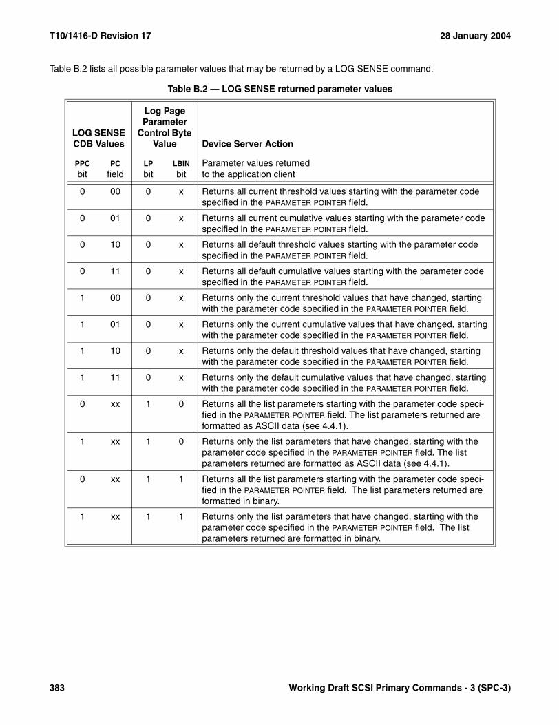
T10/1416-D Revision 17 28 January 2004
Table B.2 lists all possible parameter values that may be returned by a LOG SENSE command.
Table B.2 — LOG SENSE returned parameter values
LOG SENSE CDB Values
Log Page Parameter
Control Byte Value Device Server Action
PPC
bitPC
fieldLP
bitLBIN
bitParameter values returnedto the application client
0 00 0 x Returns all current threshold values starting with the parameter code specified in the PARAMETER POINTER field.
0 01 0 x Returns all current cumulative values starting with the parameter code specified in the PARAMETER POINTER field.
0 10 0 x Returns all default threshold values starting with the parameter code specified in the PARAMETER POINTER field.
0 11 0 x Returns all default cumulative values starting with the parameter code specified in the PARAMETER POINTER field.
1 00 0 x Returns only the current threshold values that have changed, starting with the parameter code specified in the PARAMETER POINTER field.
1 01 0 x Returns only the current cumulative values that have changed, starting with the parameter code specified in the PARAMETER POINTER field.
1 10 0 x Returns only the default threshold values that have changed, starting with the parameter code specified in the PARAMETER POINTER field.
1 11 0 x Returns only the default cumulative values that have changed, starting with the parameter code specified in the PARAMETER POINTER field.
0 xx 1 0 Returns all the list parameters starting with the parameter code speci-fied in the PARAMETER POINTER field. The list parameters returned are formatted as ASCII data (see 4.4.1).
1 xx 1 0 Returns only the list parameters that have changed, starting with the parameter code specified in the PARAMETER POINTER field. The list parameters returned are formatted as ASCII data (see 4.4.1).
0 xx 1 1 Returns all the list parameters starting with the parameter code speci-fied in the PARAMETER POINTER field. The list parameters returned are formatted in binary.
1 xx 1 1 Returns only the list parameters that have changed, starting with the parameter code specified in the PARAMETER POINTER field. The list parameters returned are formatted in binary.
383 Working Draft SCSI Primary Commands - 3 (SPC-3)

28 January 2004 T10/1416-D Revision 17
Table B.3 lists all possible save options for the LOG SENSE command.
The listed options define the save operations that occur as a direct result of the LOG SENSE command. Furthersave operations are a function of the TSD bit in the log parameter control byte (see 7.2) and the GLTSD bit in theControl mode page (see 7.4.6).
Table B.3 — LOG SENSE save options
LOG SENSE CDB Values
Log Page Parameter Control Byte Value
Device Server ActionSP
bitPC
fieldDS
bitLP
bitLBIN
bit
0 xx x x x Do not save any of the log parameters into nonvolatile storage.
1 00 0 0 x Save all the current threshold values of the selected log page into nonvolatile storage.
1 01 0 0 x Save all the current cumulative values of the selected log page into nonvolatile storage.
1 10 0 0 x Save all the default threshold values of the selected log page into nonvolatile storage.
1 11 0 0 x Save all the default cumulative values of the selected log page into nonvolatile storage.
1 xx 0 1 0 Save all the current list parameter values of the selected log page into nonvolatile storage. The list parameters are formatted as ASCII data (see 4.4.1).
1 xx 0 1 1 Save all the current list parameter values of the selected log page into nonvolatile storage. The list parameters are formatted in binary.
1 xx 1 x x Do not save any of the log parameters into nonvolatile storage.
Working Draft SCSI Primary Commands - 3 (SPC-3) 384
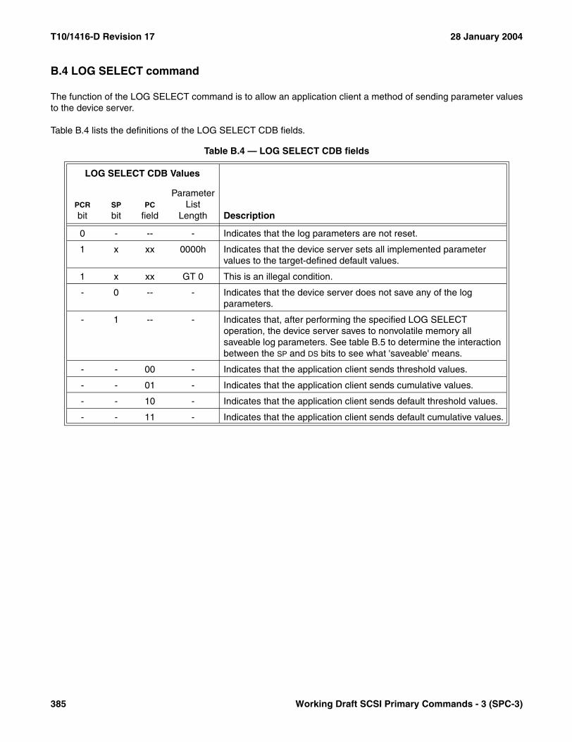
T10/1416-D Revision 17 28 January 2004
B.4 LOG SELECT command
The function of the LOG SELECT command is to allow an application client a method of sending parameter valuesto the device server.
Table B.4 lists the definitions of the LOG SELECT CDB fields.
Table B.4 — LOG SELECT CDB fields
LOG SELECT CDB Values
DescriptionPCR
bitSP
bitPC
field
Parameter List
Length
0 - -- - Indicates that the log parameters are not reset.
1 x xx 0000h Indicates that the device server sets all implemented parameter values to the target-defined default values.
1 x xx GT 0 This is an illegal condition.
- 0 -- - Indicates that the device server does not save any of the log parameters.
- 1 -- - Indicates that, after performing the specified LOG SELECT operation, the device server saves to nonvolatile memory all saveable log parameters. See table B.5 to determine the interaction between the SP and DS bits to see what 'saveable' means.
- - 00 - Indicates that the application client sends threshold values.
- - 01 - Indicates that the application client sends cumulative values.
- - 10 - Indicates that the application client sends default threshold values.
- - 11 - Indicates that the application client sends default cumulative values.
385 Working Draft SCSI Primary Commands - 3 (SPC-3)

28 January 2004 T10/1416-D Revision 17
Table B.5 lists all possible save options for the LOG SELECT command.
All the log parameters that are selected for saving are saved to nonvolatile storage after the device server performsthe specified LOG SELECT operation. Further save operations are a function of the TSD bit in the log parametercontrol byte (see 7.2) and the GLTSD bit in the Control mode page (see 7.4.6).
Table B.5 — LOG SELECT save options
LOG SELECT CDB Values
Log Page Parameter Control Byte Value
Device Server ActionSP
bitPC
fieldDS
bitLP
bitLBIN
bit
0 xx x x x Do not save any of the log parameters into nonvolatile storage.
1 00 0 0 x Save all the threshold values of the selected log page into nonvolatile storage.
1 01 0 0 x Save all the cumulative values of the selected log page into nonvolatile storage.
1 10 0 0 x Save all the default threshold values of the selected log page into nonvolatile storage.
1 11 0 0 x Save all the default cumulative values of the selected log page into nonvolatile storage.
1 xx 0 1 0 Save all the list parameter values of the selected log page into nonvolatile storage. The list parameters are formatted as ASCII data (see 4.4.1).
1 xx 0 1 1 Save all the list parameter values of the selected log page into nonvolatile storage. The list parameters are formatted in binary.
1 xx 1 x x Do not save any of the log parameters into nonvolatile storage.
Working Draft SCSI Primary Commands - 3 (SPC-3) 386

T10/1416-D Revision 17 28 January 2004
Table A.6 lists all possible parameter values that may be controlled by a LOG SELECT command.
Table B.6 — LOG SELECT controller parameter values
LOG SELECTCDB Values
Log Page Parameter
Control Byte Value Device Server Action
PC
fieldLP
bitLBIN
bit Updated parameter value usage
00 0 x The parameter values for all the log parameters in the log page(s) sent to the device server are used as threshold values, unless the LP bit is set.
01 0 x The parameter values for all the log parameters in the log page(s) sent to the device server are used as cumulative values, unless the LP bit is set.
10 0 x The device server sets the current threshold values to the default threshold values for all the log parameters specified in the log page(s) sent during a LOG SELECT command, unless the LP bit is set.
11 0 x The device server sets the current cumulative values to the default cumulative values for all the log parameters specified in the log page(s) sent during a LOG SELECT command, unless the LP bit is set.
xx 1 0 The device server replaces the current list parameter with the list parameter sent to the device server. The list parameters are formatted as ASCII data (see 4.4.1).
xx 1 1 The device server replaces the current list parameter with the list parameter sent to the device server. The list parameters are formatted in binary.
387 Working Draft SCSI Primary Commands - 3 (SPC-3)
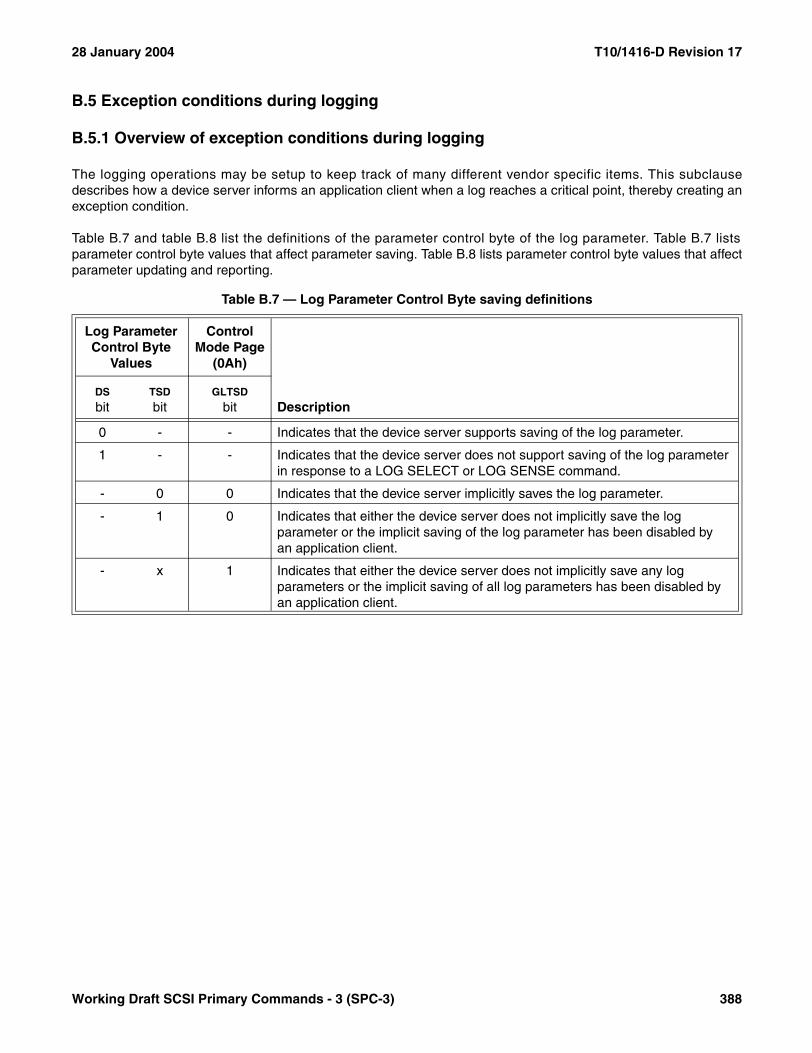
28 January 2004 T10/1416-D Revision 17
B.5 Exception conditions during logging
B.5.1 Overview of exception conditions during logging
The logging operations may be setup to keep track of many different vendor specific items. This subclausedescribes how a device server informs an application client when a log reaches a critical point, thereby creating anexception condition.
Table B.7 and table B.8 list the definitions of the parameter control byte of the log parameter. Table B.7 listsparameter control byte values that affect parameter saving. Table B.8 lists parameter control byte values that affectparameter updating and reporting.
Table B.7 — Log Parameter Control Byte saving definitions
Log Parameter Control Byte
Values
ControlMode Page
(0Ah)
DescriptionDS
bitTSD
bitGLTSD
bit
0 - - Indicates that the device server supports saving of the log parameter.
1 - - Indicates that the device server does not support saving of the log parameter in response to a LOG SELECT or LOG SENSE command.
- 0 0 Indicates that the device server implicitly saves the log parameter.
- 1 0 Indicates that either the device server does not implicitly save the log parameter or the implicit saving of the log parameter has been disabled by an application client.
- x 1 Indicates that either the device server does not implicitly save any log parameters or the implicit saving of all log parameters has been disabled by an application client.
Working Draft SCSI Primary Commands - 3 (SPC-3) 388
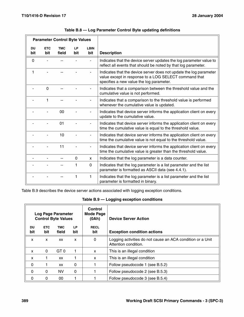
T10/1416-D Revision 17 28 January 2004
Table B.9 describes the device server actions associated with logging exception conditions.
Table B.8 — Log Parameter Control Byte updating definitions
Parameter Control Byte Values
DescriptionDU
bitETC
bitTMC
fieldLP
bitLBIN
bit
0 - -- - - Indicates that the device server updates the log parameter value to reflect all events that should be noted by that log parameter.
1 - -- - - Indicates that the device server does not update the log parameter value except in response to a LOG SELECT command that specifies a new value the log parameter.
- 0 -- - - Indicates that a comparison between the threshold value and the cumulative value is not performed.
- 1 -- - - Indicates that a comparison to the threshold value is performed whenever the cumulative value is updated.
- - 00 - - Indicates that device server informs the application client on every update to the cumulative value.
- - 01 - - Indicates that device server informs the application client on every time the cumulative value is equal to the threshold value.
- - 10 - - Indicates that device server informs the application client on every time the cumulative value is not equal to the threshold value.
- - 11 - - Indicates that device server informs the application client on every time the cumulative value is greater than the threshold value.
- - -- 0 x Indicates that the log parameter is a data counter.
- - -- 1 0 Indicates that the log parameter is a list parameter and the list parameter is formatted as ASCII data (see 4.4.1).
- - -- 1 1 Indicates that the log parameter is a list parameter and the list parameter is formatted in binary.
Table B.9 — Logging exception conditions
Log Page ParameterControl Byte Values
ControlMode Page
(0Ah) Device Server Action
DU
bitETC
bitTMC
fieldLP
bitRECL
bit Exception condition actions
x x xx x 0 Logging activities do not cause an ACA condition or a Unit Attention condition.
x 0 GT 0 1 x This is an illegal condition
x 1 xx 1 x This is an illegal condition
0 1 xx 0 1 Follow pseudocode 1 (see B.5.2)
0 0 NV 0 1 Follow pseudocode 2 (see B.5.3)
0 0 00 1 1 Follow pseudocode 3 (see B.5.4)
389 Working Draft SCSI Primary Commands - 3 (SPC-3)
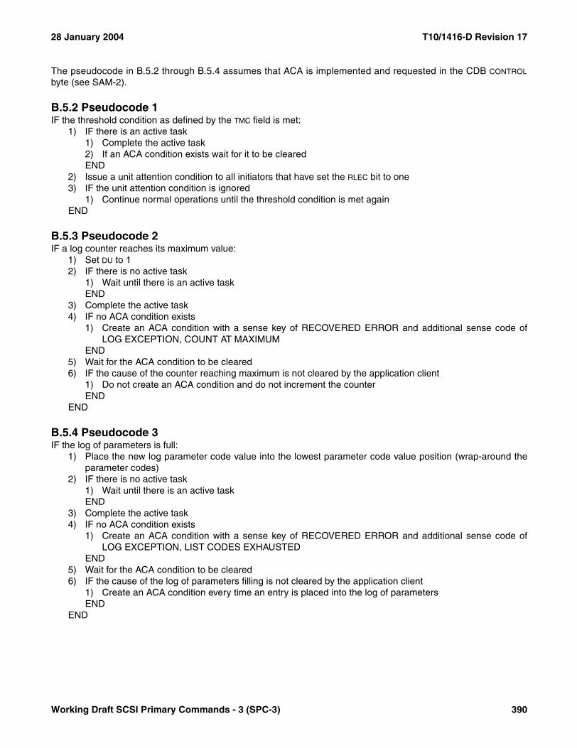
28 January 2004 T10/1416-D Revision 17
The pseudocode in B.5.2 through B.5.4 assumes that ACA is implemented and requested in the CDB CONTROL
byte (see SAM-2).
B.5.2 Pseudocode 1IF the threshold condition as defined by the TMC field is met:
1) IF there is an active task1) Complete the active task2) If an ACA condition exists wait for it to be clearedEND
2) Issue a unit attention condition to all initiators that have set the RLEC bit to one3) IF the unit attention condition is ignored
1) Continue normal operations until the threshold condition is met againEND
B.5.3 Pseudocode 2IF a log counter reaches its maximum value:
1) Set DU to 12) IF there is no active task
1) Wait until there is an active taskEND
3) Complete the active task4) IF no ACA condition exists
1) Create an ACA condition with a sense key of RECOVERED ERROR and additional sense code ofLOG EXCEPTION, COUNT AT MAXIMUM
END5) Wait for the ACA condition to be cleared6) IF the cause of the counter reaching maximum is not cleared by the application client
1) Do not create an ACA condition and do not increment the counterEND
END
B.5.4 Pseudocode 3IF the log of parameters is full:
1) Place the new log parameter code value into the lowest parameter code value position (wrap-around theparameter codes)
2) IF there is no active task1) Wait until there is an active taskEND
3) Complete the active task4) IF no ACA condition exists
1) Create an ACA condition with a sense key of RECOVERED ERROR and additional sense code ofLOG EXCEPTION, LIST CODES EXHAUSTED
END5) Wait for the ACA condition to be cleared6) IF the cause of the log of parameters filling is not cleared by the application client
1) Create an ACA condition every time an entry is placed into the log of parametersEND
END
Working Draft SCSI Primary Commands - 3 (SPC-3) 390
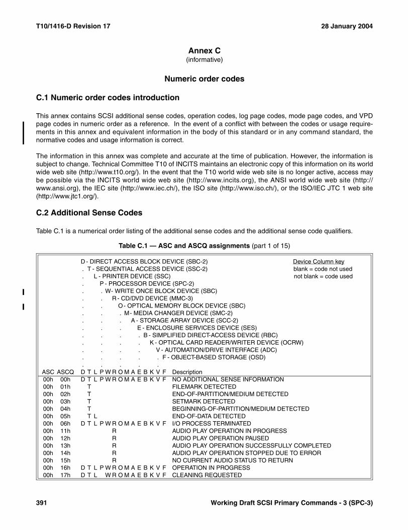
T10/1416-D Revision 17 28 January 2004
Annex C(informative)
Numeric order codes
C.1 Numeric order codes introduction
This annex contains SCSI additional sense codes, operation codes, log page codes, mode page codes, and VPDpage codes in numeric order as a reference. In the event of a conflict with between the codes or usage require-ments in this annex and equivalent information in the body of this standard or in any command standard, thenormative codes and usage information is correct.
The information in this annex was complete and accurate at the time of publication. However, the information issubject to change. Technical Committee T10 of INCITS maintains an electronic copy of this information on its worldwide web site (http://www.t10.org/). In the event that the T10 world wide web site is no longer active, access maybe possible via the INCITS world wide web site (http://www.incits.org), the ANSI world wide web site (http://www.ansi.org), the IEC site (http://www.iec.ch/), the ISO site (http://www.iso.ch/), or the ISO/IEC JTC 1 web site(http://www.jtc1.org/).
C.2 Additional Sense Codes
Table C.1 is a numerical order listing of the additional sense codes and the additional sense code qualifiers.
Table C.1 — ASC and ASCQ assignments (part 1 of 15)
D - DIRECT ACCESS BLOCK DEVICE (SBC-2) Device Column key. T - SEQUENTIAL ACCESS DEVICE (SSC-2) blank = code not used. L - PRINTER DEVICE (SSC) not blank = code used. P - PROCESSOR DEVICE (SPC-2). . W- WRITE ONCE BLOCK DEVICE (SBC). . R - CD/DVD DEVICE (MMC-3). . O- OPTICAL MEMORY BLOCK DEVICE (SBC). . . M- MEDIA CHANGER DEVICE (SMC-2). . . A - STORAGE ARRAY DEVICE (SCC-2). . . E - ENCLOSURE SERVICES DEVICE (SES). . . . B - SIMPLIFIED DIRECT-ACCESS DEVICE (RBC). . . . K - OPTICAL CARD READER/WRITER DEVICE (OCRW). . . . V - AUTOMATION/DRIVE INTERFACE (ADC). . . . . F - OBJECT-BASED STORAGE (OSD). . . . .
ASC ASCQ D T L P W R O M A E B K V F Description00h 00h D T L P W R O M A E B K V F NO ADDITIONAL SENSE INFORMATION00h 01h T FILEMARK DETECTED00h 02h T END-OF-PARTITION/MEDIUM DETECTED00h 03h T SETMARK DETECTED00h 04h T BEGINNING-OF-PARTITION/MEDIUM DETECTED00h 05h T L END-OF-DATA DETECTED00h 06h D T L P W R O M A E B K V F I/O PROCESS TERMINATED00h 11h R AUDIO PLAY OPERATION IN PROGRESS00h 12h R AUDIO PLAY OPERATION PAUSED00h 13h R AUDIO PLAY OPERATION SUCCESSFULLY COMPLETED00h 14h R AUDIO PLAY OPERATION STOPPED DUE TO ERROR00h 15h R NO CURRENT AUDIO STATUS TO RETURN00h 16h D T L P W R O M A E B K V F OPERATION IN PROGRESS00h 17h D T L W R O M A E B K V F CLEANING REQUESTED
391 Working Draft SCSI Primary Commands - 3 (SPC-3)

28 January 2004 T10/1416-D Revision 17
00h 18h T ERASE OPERATION IN PROGRESS00h 19h T LOCATE OPERATION IN PROGRESS00h 1Ah T REWIND OPERATION IN PROGRESS00h 1Bh T SET CAPACITY OPERATION IN PROGRESS00h 1Ch T VERIFY OPERATION IN PROGRESS01h 00h D W O B K NO INDEX/SECTOR SIGNAL02h 00h D W R O M B K NO SEEK COMPLETE03h 00h D T L W O B K PERIPHERAL DEVICE WRITE FAULT03h 01h T NO WRITE CURRENT03h 02h T EXCESSIVE WRITE ERRORS04h 00h D T L P W R O M A E B K V F LOGICAL UNIT NOT READY, CAUSE NOT REPORTABLE04h 01h D T L P W R O M A E B K V F LOGICAL UNIT IS IN PROCESS OF BECOMING READY04h 02h D T L P W R O M A E B K V F LOGICAL UNIT NOT READY, INITIALIZING COMMAND REQUIRED04h 03h D T L P W R O M A E B K V F LOGICAL UNIT NOT READY, MANUAL INTERVENTION REQUIRED04h 04h D T L R O B LOGICAL UNIT NOT READY, FORMAT IN PROGRESS04h 05h D T W O M A B K LOGICAL UNIT NOT READY, REBUILD IN PROGRESS04h 06h D T W O M A B K LOGICAL UNIT NOT READY, RECALCULATION IN PROGRESS04h 07h D T L P W R O M A E B K V F LOGICAL UNIT NOT READY, OPERATION IN PROGRESS04h 08h R LOGICAL UNIT NOT READY, LONG WRITE IN PROGRESS04h 09h D T L P W R O M A E B K V F LOGICAL UNIT NOT READY, SELF-TEST IN PROGRESS
04h 0Ah D T L P W R O M A E B K V FLOGICAL UNIT NOT ACCESSIBLE, ASYMMETRIC ACCESS STATE TRANSITION
04h 0Bh D T L P W R O M A E B K V F LOGICAL UNIT NOT ACCESSIBLE, TARGET PORT IN STANDBY STATE
04h 0Ch D T L P W R O M A E B K V FLOGICAL UNIT NOT ACCESSIBLE, TARGET PORT IN UNAVAILABLE STATE
04h 10h D T W R O M B LOGICAL UNIT NOT READY, AUXILIARY MEMORY NOT ACCESSIBLE04h 11h D T W R O M A E B V F LOGICAL UNIT NOT READY, NOTIFY (ENABLE SPINUP) REQUIRED05h 00h D T L W R O M A E B K V F LOGICAL UNIT DOES NOT RESPOND TO SELECTION06h 00h D W R O M B K NO REFERENCE POSITION FOUND07h 00h D T L W R O M B K MULTIPLE PERIPHERAL DEVICES SELECTED08h 00h D T L W R O M A E B K V F LOGICAL UNIT COMMUNICATION FAILURE08h 01h D T L W R O M A E B K V F LOGICAL UNIT COMMUNICATION TIME-OUT08h 02h D T L W R O M A E B K V F LOGICAL UNIT COMMUNICATION PARITY ERROR08h 03h D T R O M B K LOGICAL UNIT COMMUNICATION CRC ERROR (ULTRA-DMA/32)08h 04h D T L P W R O K UNREACHABLE COPY TARGET09h 00h D T W R O B TRACK FOLLOWING ERROR09h 01h W R O K TRACKING SERVO FAILURE09h 02h W R O K FOCUS SERVO FAILURE09h 03h W R O SPINDLE SERVO FAILURE09h 04h D T W R O B HEAD SELECT FAULT
Table C.1 — ASC and ASCQ assignments (part 2 of 15)
D - DIRECT ACCESS BLOCK DEVICE (SBC-2) Device Column key. T - SEQUENTIAL ACCESS DEVICE (SSC-2) blank = code not used. L - PRINTER DEVICE (SSC) not blank = code used. P - PROCESSOR DEVICE (SPC-2). . W- WRITE ONCE BLOCK DEVICE (SBC). . R - CD/DVD DEVICE (MMC-3). . O- OPTICAL MEMORY BLOCK DEVICE (SBC). . . M- MEDIA CHANGER DEVICE (SMC-2). . . A - STORAGE ARRAY DEVICE (SCC-2). . . E - ENCLOSURE SERVICES DEVICE (SES). . . . B - SIMPLIFIED DIRECT-ACCESS DEVICE (RBC). . . . K - OPTICAL CARD READER/WRITER DEVICE (OCRW). . . . V - AUTOMATION/DRIVE INTERFACE (ADC). . . . . F - OBJECT-BASED STORAGE (OSD). . . . .
ASC ASCQ D T L P W R O M A E B K V F Description
Working Draft SCSI Primary Commands - 3 (SPC-3) 392
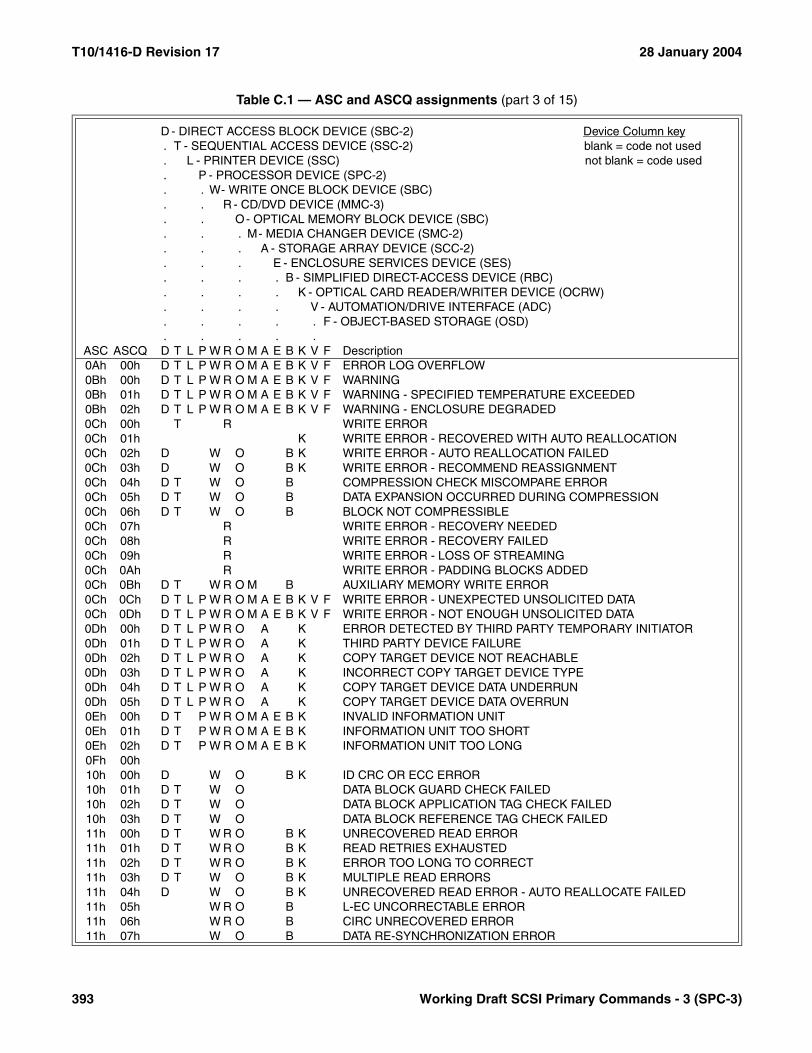
T10/1416-D Revision 17 28 January 2004
0Ah 00h D T L P W R O M A E B K V F ERROR LOG OVERFLOW0Bh 00h D T L P W R O M A E B K V F WARNING0Bh 01h D T L P W R O M A E B K V F WARNING - SPECIFIED TEMPERATURE EXCEEDED0Bh 02h D T L P W R O M A E B K V F WARNING - ENCLOSURE DEGRADED0Ch 00h T R WRITE ERROR0Ch 01h K WRITE ERROR - RECOVERED WITH AUTO REALLOCATION0Ch 02h D W O B K WRITE ERROR - AUTO REALLOCATION FAILED0Ch 03h D W O B K WRITE ERROR - RECOMMEND REASSIGNMENT0Ch 04h D T W O B COMPRESSION CHECK MISCOMPARE ERROR0Ch 05h D T W O B DATA EXPANSION OCCURRED DURING COMPRESSION0Ch 06h D T W O B BLOCK NOT COMPRESSIBLE0Ch 07h R WRITE ERROR - RECOVERY NEEDED0Ch 08h R WRITE ERROR - RECOVERY FAILED0Ch 09h R WRITE ERROR - LOSS OF STREAMING0Ch 0Ah R WRITE ERROR - PADDING BLOCKS ADDED0Ch 0Bh D T W R O M B AUXILIARY MEMORY WRITE ERROR0Ch 0Ch D T L P W R O M A E B K V F WRITE ERROR - UNEXPECTED UNSOLICITED DATA0Ch 0Dh D T L P W R O M A E B K V F WRITE ERROR - NOT ENOUGH UNSOLICITED DATA0Dh 00h D T L P W R O A K ERROR DETECTED BY THIRD PARTY TEMPORARY INITIATOR0Dh 01h D T L P W R O A K THIRD PARTY DEVICE FAILURE0Dh 02h D T L P W R O A K COPY TARGET DEVICE NOT REACHABLE0Dh 03h D T L P W R O A K INCORRECT COPY TARGET DEVICE TYPE0Dh 04h D T L P W R O A K COPY TARGET DEVICE DATA UNDERRUN0Dh 05h D T L P W R O A K COPY TARGET DEVICE DATA OVERRUN0Eh 00h D T P W R O M A E B K INVALID INFORMATION UNIT0Eh 01h D T P W R O M A E B K INFORMATION UNIT TOO SHORT0Eh 02h D T P W R O M A E B K INFORMATION UNIT TOO LONG0Fh 00h10h 00h D W O B K ID CRC OR ECC ERROR10h 01h D T W O DATA BLOCK GUARD CHECK FAILED10h 02h D T W O DATA BLOCK APPLICATION TAG CHECK FAILED10h 03h D T W O DATA BLOCK REFERENCE TAG CHECK FAILED11h 00h D T W R O B K UNRECOVERED READ ERROR11h 01h D T W R O B K READ RETRIES EXHAUSTED11h 02h D T W R O B K ERROR TOO LONG TO CORRECT11h 03h D T W O B K MULTIPLE READ ERRORS11h 04h D W O B K UNRECOVERED READ ERROR - AUTO REALLOCATE FAILED11h 05h W R O B L-EC UNCORRECTABLE ERROR11h 06h W R O B CIRC UNRECOVERED ERROR11h 07h W O B DATA RE-SYNCHRONIZATION ERROR
Table C.1 — ASC and ASCQ assignments (part 3 of 15)
D - DIRECT ACCESS BLOCK DEVICE (SBC-2) Device Column key. T - SEQUENTIAL ACCESS DEVICE (SSC-2) blank = code not used. L - PRINTER DEVICE (SSC) not blank = code used. P - PROCESSOR DEVICE (SPC-2). . W- WRITE ONCE BLOCK DEVICE (SBC). . R - CD/DVD DEVICE (MMC-3). . O- OPTICAL MEMORY BLOCK DEVICE (SBC). . . M- MEDIA CHANGER DEVICE (SMC-2). . . A - STORAGE ARRAY DEVICE (SCC-2). . . E - ENCLOSURE SERVICES DEVICE (SES). . . . B - SIMPLIFIED DIRECT-ACCESS DEVICE (RBC). . . . K - OPTICAL CARD READER/WRITER DEVICE (OCRW). . . . V - AUTOMATION/DRIVE INTERFACE (ADC). . . . . F - OBJECT-BASED STORAGE (OSD). . . . .
ASC ASCQ D T L P W R O M A E B K V F Description
393 Working Draft SCSI Primary Commands - 3 (SPC-3)
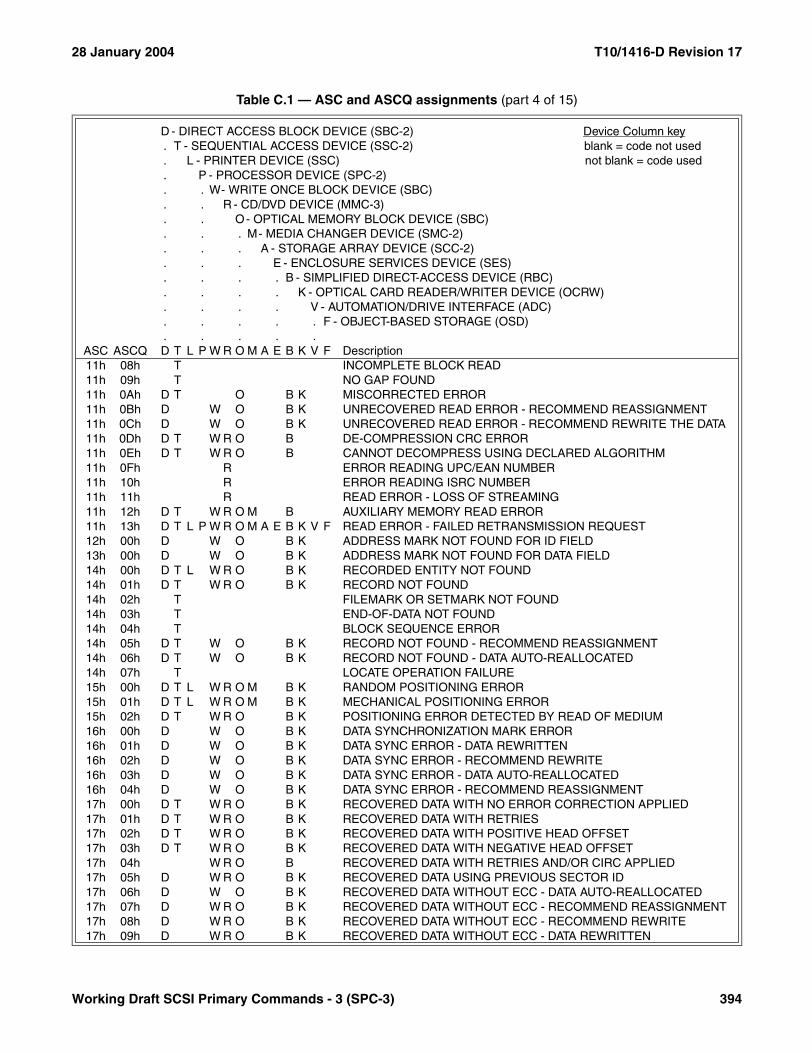
28 January 2004 T10/1416-D Revision 17
11h 08h T INCOMPLETE BLOCK READ11h 09h T NO GAP FOUND11h 0Ah D T O B K MISCORRECTED ERROR11h 0Bh D W O B K UNRECOVERED READ ERROR - RECOMMEND REASSIGNMENT11h 0Ch D W O B K UNRECOVERED READ ERROR - RECOMMEND REWRITE THE DATA11h 0Dh D T W R O B DE-COMPRESSION CRC ERROR11h 0Eh D T W R O B CANNOT DECOMPRESS USING DECLARED ALGORITHM11h 0Fh R ERROR READING UPC/EAN NUMBER11h 10h R ERROR READING ISRC NUMBER11h 11h R READ ERROR - LOSS OF STREAMING11h 12h D T W R O M B AUXILIARY MEMORY READ ERROR11h 13h D T L P W R O M A E B K V F READ ERROR - FAILED RETRANSMISSION REQUEST12h 00h D W O B K ADDRESS MARK NOT FOUND FOR ID FIELD13h 00h D W O B K ADDRESS MARK NOT FOUND FOR DATA FIELD14h 00h D T L W R O B K RECORDED ENTITY NOT FOUND14h 01h D T W R O B K RECORD NOT FOUND14h 02h T FILEMARK OR SETMARK NOT FOUND14h 03h T END-OF-DATA NOT FOUND14h 04h T BLOCK SEQUENCE ERROR14h 05h D T W O B K RECORD NOT FOUND - RECOMMEND REASSIGNMENT14h 06h D T W O B K RECORD NOT FOUND - DATA AUTO-REALLOCATED14h 07h T LOCATE OPERATION FAILURE15h 00h D T L W R O M B K RANDOM POSITIONING ERROR15h 01h D T L W R O M B K MECHANICAL POSITIONING ERROR15h 02h D T W R O B K POSITIONING ERROR DETECTED BY READ OF MEDIUM16h 00h D W O B K DATA SYNCHRONIZATION MARK ERROR16h 01h D W O B K DATA SYNC ERROR - DATA REWRITTEN16h 02h D W O B K DATA SYNC ERROR - RECOMMEND REWRITE16h 03h D W O B K DATA SYNC ERROR - DATA AUTO-REALLOCATED16h 04h D W O B K DATA SYNC ERROR - RECOMMEND REASSIGNMENT17h 00h D T W R O B K RECOVERED DATA WITH NO ERROR CORRECTION APPLIED17h 01h D T W R O B K RECOVERED DATA WITH RETRIES17h 02h D T W R O B K RECOVERED DATA WITH POSITIVE HEAD OFFSET17h 03h D T W R O B K RECOVERED DATA WITH NEGATIVE HEAD OFFSET17h 04h W R O B RECOVERED DATA WITH RETRIES AND/OR CIRC APPLIED17h 05h D W R O B K RECOVERED DATA USING PREVIOUS SECTOR ID17h 06h D W O B K RECOVERED DATA WITHOUT ECC - DATA AUTO-REALLOCATED17h 07h D W R O B K RECOVERED DATA WITHOUT ECC - RECOMMEND REASSIGNMENT17h 08h D W R O B K RECOVERED DATA WITHOUT ECC - RECOMMEND REWRITE17h 09h D W R O B K RECOVERED DATA WITHOUT ECC - DATA REWRITTEN
Table C.1 — ASC and ASCQ assignments (part 4 of 15)
D - DIRECT ACCESS BLOCK DEVICE (SBC-2) Device Column key. T - SEQUENTIAL ACCESS DEVICE (SSC-2) blank = code not used. L - PRINTER DEVICE (SSC) not blank = code used. P - PROCESSOR DEVICE (SPC-2). . W- WRITE ONCE BLOCK DEVICE (SBC). . R - CD/DVD DEVICE (MMC-3). . O- OPTICAL MEMORY BLOCK DEVICE (SBC). . . M- MEDIA CHANGER DEVICE (SMC-2). . . A - STORAGE ARRAY DEVICE (SCC-2). . . E - ENCLOSURE SERVICES DEVICE (SES). . . . B - SIMPLIFIED DIRECT-ACCESS DEVICE (RBC). . . . K - OPTICAL CARD READER/WRITER DEVICE (OCRW). . . . V - AUTOMATION/DRIVE INTERFACE (ADC). . . . . F - OBJECT-BASED STORAGE (OSD). . . . .
ASC ASCQ D T L P W R O M A E B K V F Description
Working Draft SCSI Primary Commands - 3 (SPC-3) 394

T10/1416-D Revision 17 28 January 2004
18h 00h D T W R O B K RECOVERED DATA WITH ERROR CORRECTION APPLIED18h 01h D W R O B K RECOVERED DATA WITH ERROR CORR. & RETRIES APPLIED18h 02h D W R O B K RECOVERED DATA - DATA AUTO-REALLOCATED18h 03h R RECOVERED DATA WITH CIRC18h 04h R RECOVERED DATA WITH L-EC18h 05h D W R O B K RECOVERED DATA - RECOMMEND REASSIGNMENT18h 06h D W R O B K RECOVERED DATA - RECOMMEND REWRITE18h 07h D W O B K RECOVERED DATA WITH ECC - DATA REWRITTEN18h 08h R RECOVERED DATA WITH LINKING19h 00h D O K DEFECT LIST ERROR19h 01h D O K DEFECT LIST NOT AVAILABLE19h 02h D O K DEFECT LIST ERROR IN PRIMARY LIST19h 03h D O K DEFECT LIST ERROR IN GROWN LIST1Ah 00h D T L P W R O M A E B K V F PARAMETER LIST LENGTH ERROR1Bh 00h D T L P W R O M A E B K V F SYNCHRONOUS DATA TRANSFER ERROR1Ch 00h D O B K DEFECT LIST NOT FOUND1Ch 01h D O B K PRIMARY DEFECT LIST NOT FOUND1Ch 02h D O B K GROWN DEFECT LIST NOT FOUND1Dh 00h D T W R O B K MISCOMPARE DURING VERIFY OPERATION1Eh 00h D W O B K RECOVERED ID WITH ECC CORRECTION1Fh 00h D O K PARTIAL DEFECT LIST TRANSFER20h 00h D T L P W R O M A E B K V F INVALID COMMAND OPERATION CODE20h 01h D T P W R O M A E B K ACCESS DENIED - INITIATOR PENDING-ENROLLED20h 02h D T P W R O M A E B K ACCESS DENIED - NO ACCESS RIGHTS20h 03h D T P W R O M A E B K ACCESS DENIED - INVALID MGMT ID KEY20h 04h T ILLEGAL COMMAND WHILE IN WRITE CAPABLE STATE20h 05h T Obsolete20h 06h T ILLEGAL COMMAND WHILE IN EXPLICIT ADDRESS MODE20h 07h T ILLEGAL COMMAND WHILE IN IMPLICIT ADDRESS MODE20h 08h D T P W R O M A E B K ACCESS DENIED - ENROLLMENT CONFLICT20h 09h D T P W R O M A E B K ACCESS DENIED - INVALID LU IDENTIFIER20h 0Ah D T P W R O M A E B K ACCESS DENIED - INVALID PROXY TOKEN20h 0Bh D T P W R O M A E B K ACCESS DENIED - ACL LUN CONFLICT21h 00h D T W R O M B K LOGICAL BLOCK ADDRESS OUT OF RANGE21h 01h D T W R O M B K INVALID ELEMENT ADDRESS21h 02h R INVALID ADDRESS FOR WRITE22h 00h D ILLEGAL FUNCTION (USE 20 00, 24 00, OR 26 00)23h 00h24h 00h D T L P W R O M A E B K V F INVALID FIELD IN CDB24h 01h D T L P W R O M A E B K V F CDB DECRYPTION ERROR
Table C.1 — ASC and ASCQ assignments (part 5 of 15)
D - DIRECT ACCESS BLOCK DEVICE (SBC-2) Device Column key. T - SEQUENTIAL ACCESS DEVICE (SSC-2) blank = code not used. L - PRINTER DEVICE (SSC) not blank = code used. P - PROCESSOR DEVICE (SPC-2). . W- WRITE ONCE BLOCK DEVICE (SBC). . R - CD/DVD DEVICE (MMC-3). . O- OPTICAL MEMORY BLOCK DEVICE (SBC). . . M- MEDIA CHANGER DEVICE (SMC-2). . . A - STORAGE ARRAY DEVICE (SCC-2). . . E - ENCLOSURE SERVICES DEVICE (SES). . . . B - SIMPLIFIED DIRECT-ACCESS DEVICE (RBC). . . . K - OPTICAL CARD READER/WRITER DEVICE (OCRW). . . . V - AUTOMATION/DRIVE INTERFACE (ADC). . . . . F - OBJECT-BASED STORAGE (OSD). . . . .
ASC ASCQ D T L P W R O M A E B K V F Description
395 Working Draft SCSI Primary Commands - 3 (SPC-3)

28 January 2004 T10/1416-D Revision 17
24h 02h T Obsolete24h 03h T Obsolete24h 04h F SECURITY AUDIT VALUE FROZEN24h 05h F SECURITY WORKING KEY FROZEN24h 06h F NONCE NOT UNIQUE24h 07h F NONCE TIMESTAMP OUT OF RANGE25h 00h D T L P W R O M A E B K V F LOGICAL UNIT NOT SUPPORTED26h 00h D T L P W R O M A E B K V F INVALID FIELD IN PARAMETER LIST26h 01h D T L P W R O M A E B K V F PARAMETER NOT SUPPORTED26h 02h D T L P W R O M A E B K V F PARAMETER VALUE INVALID26h 03h D T L P W R O M A E K THRESHOLD PARAMETERS NOT SUPPORTED26h 04h D T L P W R O M A E B K V F INVALID RELEASE OF PERSISTENT RESERVATION26h 05h D T L P W R O M A B K DATA DECRYPTION ERROR26h 06h D T L P W R O K TOO MANY TARGET DESCRIPTORS26h 07h D T L P W R O K UNSUPPORTED TARGET DESCRIPTOR TYPE CODE26h 08h D T L P W R O K TOO MANY SEGMENT DESCRIPTORS26h 09h D T L P W R O K UNSUPPORTED SEGMENT DESCRIPTOR TYPE CODE26h 0Ah D T L P W R O K UNEXPECTED INEXACT SEGMENT26h 0Bh D T L P W R O K INLINE DATA LENGTH EXCEEDED26h 0Ch D T L P W R O K INVALID OPERATION FOR COPY SOURCE OR DESTINATION26h 0Dh D T L P W R O K COPY SEGMENT GRANULARITY VIOLATION26h 0Eh D T P W R O M A E B K INVALID PARAMETER WHILE PORT IS ENABLED26h 0Fh F INVALID DATA-OUT BUFFER INTEGRITY CHECK VALUE27h 00h D T W R O B K WRITE PROTECTED27h 01h D T W R O B K HARDWARE WRITE PROTECTED27h 02h D T W R O B K LOGICAL UNIT SOFTWARE WRITE PROTECTED27h 03h T R ASSOCIATED WRITE PROTECT27h 04h T R PERSISTENT WRITE PROTECT27h 05h T R PERMANENT WRITE PROTECT27h 06h R CONDITIONAL WRITE PROTECT28h 00h D T L P W R O M A E B K V F NOT READY TO READY CHANGE, MEDIUM MAY HAVE CHANGED28h 01h D T W R O M B IMPORT OR EXPORT ELEMENT ACCESSED29h 00h D T L P W R O M A E B K V F POWER ON, RESET, OR BUS DEVICE RESET OCCURRED29h 01h D T L P W R O M A E B K V F POWER ON OCCURRED29h 02h D T L P W R O M A E B K V F SCSI BUS RESET OCCURRED29h 03h D T L P W R O M A E B K V F BUS DEVICE RESET FUNCTION OCCURRED29h 04h D T L P W R O M A E B K V F DEVICE INTERNAL RESET29h 05h D T L P W R O M A E B K V F TRANSCEIVER MODE CHANGED TO SINGLE-ENDED29h 06h D T L P W R O M A E B K V F TRANSCEIVER MODE CHANGED TO LVD29h 07h D T L P W R O M A E B K V F I_T NEXUS LOSS OCCURRED
Table C.1 — ASC and ASCQ assignments (part 6 of 15)
D - DIRECT ACCESS BLOCK DEVICE (SBC-2) Device Column key. T - SEQUENTIAL ACCESS DEVICE (SSC-2) blank = code not used. L - PRINTER DEVICE (SSC) not blank = code used. P - PROCESSOR DEVICE (SPC-2). . W- WRITE ONCE BLOCK DEVICE (SBC). . R - CD/DVD DEVICE (MMC-3). . O- OPTICAL MEMORY BLOCK DEVICE (SBC). . . M- MEDIA CHANGER DEVICE (SMC-2). . . A - STORAGE ARRAY DEVICE (SCC-2). . . E - ENCLOSURE SERVICES DEVICE (SES). . . . B - SIMPLIFIED DIRECT-ACCESS DEVICE (RBC). . . . K - OPTICAL CARD READER/WRITER DEVICE (OCRW). . . . V - AUTOMATION/DRIVE INTERFACE (ADC). . . . . F - OBJECT-BASED STORAGE (OSD). . . . .
ASC ASCQ D T L P W R O M A E B K V F Description
Working Draft SCSI Primary Commands - 3 (SPC-3) 396
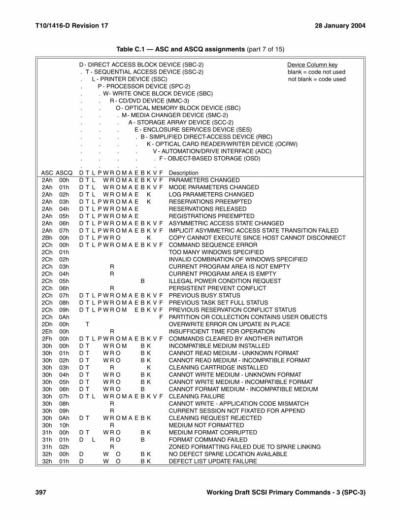
T10/1416-D Revision 17 28 January 2004
2Ah 00h D T L W R O M A E B K V F PARAMETERS CHANGED2Ah 01h D T L W R O M A E B K V F MODE PARAMETERS CHANGED2Ah 02h D T L W R O M A E K LOG PARAMETERS CHANGED2Ah 03h D T L P W R O M A E K RESERVATIONS PREEMPTED2Ah 04h D T L P W R O M A E RESERVATIONS RELEASED2Ah 05h D T L P W R O M A E REGISTRATIONS PREEMPTED2Ah 06h D T L P W R O M A E B K V F ASYMMETRIC ACCESS STATE CHANGED2Ah 07h D T L P W R O M A E B K V F IMPLICIT ASYMMETRIC ACCESS STATE TRANSITION FAILED2Bh 00h D T L P W R O K COPY CANNOT EXECUTE SINCE HOST CANNOT DISCONNECT2Ch 00h D T L P W R O M A E B K V F COMMAND SEQUENCE ERROR2Ch 01h TOO MANY WINDOWS SPECIFIED2Ch 02h INVALID COMBINATION OF WINDOWS SPECIFIED2Ch 03h R CURRENT PROGRAM AREA IS NOT EMPTY2Ch 04h R CURRENT PROGRAM AREA IS EMPTY2Ch 05h B ILLEGAL POWER CONDITION REQUEST2Ch 06h R PERSISTENT PREVENT CONFLICT2Ch 07h D T L P W R O M A E B K V F PREVIOUS BUSY STATUS2Ch 08h D T L P W R O M A E B K V F PREVIOUS TASK SET FULL STATUS2Ch 09h D T L P W R O M E B K V F PREVIOUS RESERVATION CONFLICT STATUS2Ch 0Ah F PARTITION OR COLLECTION CONTAINS USER OBJECTS2Dh 00h T OVERWRITE ERROR ON UPDATE IN PLACE2Eh 00h R INSUFFICIENT TIME FOR OPERATION2Fh 00h D T L P W R O M A E B K V F COMMANDS CLEARED BY ANOTHER INITIATOR30h 00h D T W R O M B K INCOMPATIBLE MEDIUM INSTALLED30h 01h D T W R O B K CANNOT READ MEDIUM - UNKNOWN FORMAT30h 02h D T W R O B K CANNOT READ MEDIUM - INCOMPATIBLE FORMAT30h 03h D T R K CLEANING CARTRIDGE INSTALLED30h 04h D T W R O B K CANNOT WRITE MEDIUM - UNKNOWN FORMAT30h 05h D T W R O B K CANNOT WRITE MEDIUM - INCOMPATIBLE FORMAT30h 06h D T W R O B CANNOT FORMAT MEDIUM - INCOMPATIBLE MEDIUM30h 07h D T L W R O M A E B K V F CLEANING FAILURE30h 08h R CANNOT WRITE - APPLICATION CODE MISMATCH30h 09h R CURRENT SESSION NOT FIXATED FOR APPEND30h 0Ah D T W R O M A E B K CLEANING REQUEST REJECTED30h 10h R MEDIUM NOT FORMATTED31h 00h D T W R O B K MEDIUM FORMAT CORRUPTED31h 01h D L R O B FORMAT COMMAND FAILED31h 02h R ZONED FORMATTING FAILED DUE TO SPARE LINKING32h 00h D W O B K NO DEFECT SPARE LOCATION AVAILABLE32h 01h D W O B K DEFECT LIST UPDATE FAILURE
Table C.1 — ASC and ASCQ assignments (part 7 of 15)
D - DIRECT ACCESS BLOCK DEVICE (SBC-2) Device Column key. T - SEQUENTIAL ACCESS DEVICE (SSC-2) blank = code not used. L - PRINTER DEVICE (SSC) not blank = code used. P - PROCESSOR DEVICE (SPC-2). . W- WRITE ONCE BLOCK DEVICE (SBC). . R - CD/DVD DEVICE (MMC-3). . O- OPTICAL MEMORY BLOCK DEVICE (SBC). . . M- MEDIA CHANGER DEVICE (SMC-2). . . A - STORAGE ARRAY DEVICE (SCC-2). . . E - ENCLOSURE SERVICES DEVICE (SES). . . . B - SIMPLIFIED DIRECT-ACCESS DEVICE (RBC). . . . K - OPTICAL CARD READER/WRITER DEVICE (OCRW). . . . V - AUTOMATION/DRIVE INTERFACE (ADC). . . . . F - OBJECT-BASED STORAGE (OSD). . . . .
ASC ASCQ D T L P W R O M A E B K V F Description
397 Working Draft SCSI Primary Commands - 3 (SPC-3)
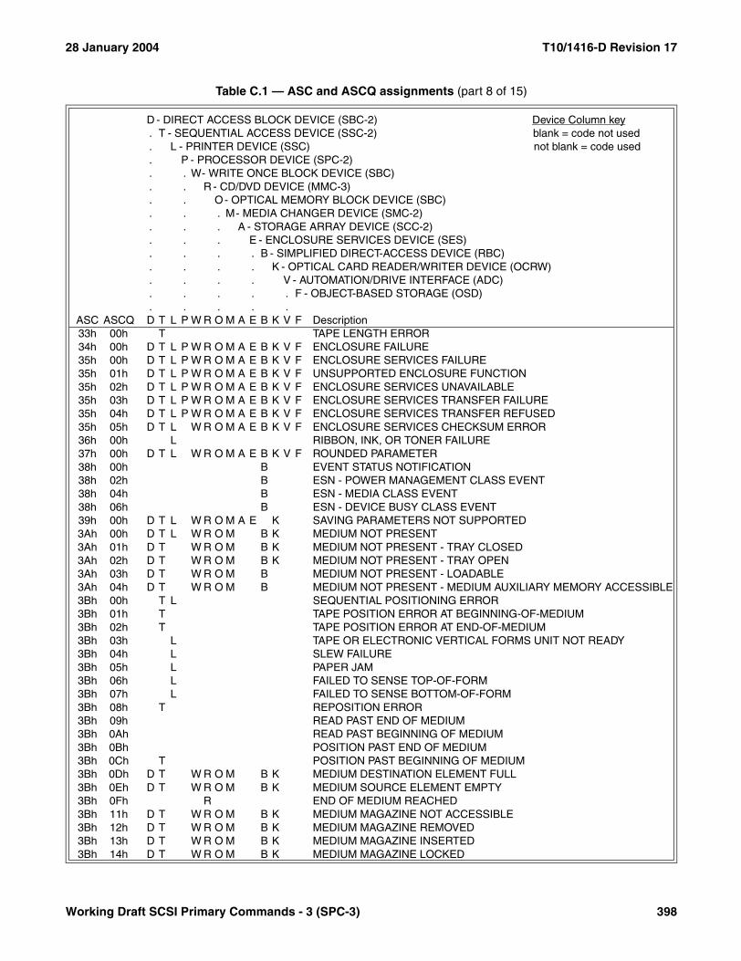
28 January 2004 T10/1416-D Revision 17
33h 00h T TAPE LENGTH ERROR34h 00h D T L P W R O M A E B K V F ENCLOSURE FAILURE35h 00h D T L P W R O M A E B K V F ENCLOSURE SERVICES FAILURE35h 01h D T L P W R O M A E B K V F UNSUPPORTED ENCLOSURE FUNCTION35h 02h D T L P W R O M A E B K V F ENCLOSURE SERVICES UNAVAILABLE35h 03h D T L P W R O M A E B K V F ENCLOSURE SERVICES TRANSFER FAILURE35h 04h D T L P W R O M A E B K V F ENCLOSURE SERVICES TRANSFER REFUSED35h 05h D T L W R O M A E B K V F ENCLOSURE SERVICES CHECKSUM ERROR36h 00h L RIBBON, INK, OR TONER FAILURE37h 00h D T L W R O M A E B K V F ROUNDED PARAMETER38h 00h B EVENT STATUS NOTIFICATION38h 02h B ESN - POWER MANAGEMENT CLASS EVENT38h 04h B ESN - MEDIA CLASS EVENT38h 06h B ESN - DEVICE BUSY CLASS EVENT39h 00h D T L W R O M A E K SAVING PARAMETERS NOT SUPPORTED3Ah 00h D T L W R O M B K MEDIUM NOT PRESENT3Ah 01h D T W R O M B K MEDIUM NOT PRESENT - TRAY CLOSED3Ah 02h D T W R O M B K MEDIUM NOT PRESENT - TRAY OPEN3Ah 03h D T W R O M B MEDIUM NOT PRESENT - LOADABLE3Ah 04h D T W R O M B MEDIUM NOT PRESENT - MEDIUM AUXILIARY MEMORY ACCESSIBLE3Bh 00h T L SEQUENTIAL POSITIONING ERROR3Bh 01h T TAPE POSITION ERROR AT BEGINNING-OF-MEDIUM3Bh 02h T TAPE POSITION ERROR AT END-OF-MEDIUM3Bh 03h L TAPE OR ELECTRONIC VERTICAL FORMS UNIT NOT READY3Bh 04h L SLEW FAILURE3Bh 05h L PAPER JAM3Bh 06h L FAILED TO SENSE TOP-OF-FORM3Bh 07h L FAILED TO SENSE BOTTOM-OF-FORM3Bh 08h T REPOSITION ERROR3Bh 09h READ PAST END OF MEDIUM3Bh 0Ah READ PAST BEGINNING OF MEDIUM3Bh 0Bh POSITION PAST END OF MEDIUM3Bh 0Ch T POSITION PAST BEGINNING OF MEDIUM3Bh 0Dh D T W R O M B K MEDIUM DESTINATION ELEMENT FULL3Bh 0Eh D T W R O M B K MEDIUM SOURCE ELEMENT EMPTY3Bh 0Fh R END OF MEDIUM REACHED3Bh 11h D T W R O M B K MEDIUM MAGAZINE NOT ACCESSIBLE3Bh 12h D T W R O M B K MEDIUM MAGAZINE REMOVED3Bh 13h D T W R O M B K MEDIUM MAGAZINE INSERTED3Bh 14h D T W R O M B K MEDIUM MAGAZINE LOCKED
Table C.1 — ASC and ASCQ assignments (part 8 of 15)
D - DIRECT ACCESS BLOCK DEVICE (SBC-2) Device Column key. T - SEQUENTIAL ACCESS DEVICE (SSC-2) blank = code not used. L - PRINTER DEVICE (SSC) not blank = code used. P - PROCESSOR DEVICE (SPC-2). . W- WRITE ONCE BLOCK DEVICE (SBC). . R - CD/DVD DEVICE (MMC-3). . O- OPTICAL MEMORY BLOCK DEVICE (SBC). . . M- MEDIA CHANGER DEVICE (SMC-2). . . A - STORAGE ARRAY DEVICE (SCC-2). . . E - ENCLOSURE SERVICES DEVICE (SES). . . . B - SIMPLIFIED DIRECT-ACCESS DEVICE (RBC). . . . K - OPTICAL CARD READER/WRITER DEVICE (OCRW). . . . V - AUTOMATION/DRIVE INTERFACE (ADC). . . . . F - OBJECT-BASED STORAGE (OSD). . . . .
ASC ASCQ D T L P W R O M A E B K V F Description
Working Draft SCSI Primary Commands - 3 (SPC-3) 398

T10/1416-D Revision 17 28 January 2004
3Bh 15h D T W R O M B K MEDIUM MAGAZINE UNLOCKED3Bh 16h R MECHANICAL POSITIONING OR CHANGER ERROR3Bh 17h F READ PAST END OF USER OBJECT3Ch 00h3Dh 00h D T L P W R O M A E K INVALID BITS IN IDENTIFY MESSAGE3Eh 00h D T L P W R O M A E B K V F LOGICAL UNIT HAS NOT SELF-CONFIGURED YET3Eh 01h D T L P W R O M A E B K V F LOGICAL UNIT FAILURE3Eh 02h D T L P W R O M A E B K V F TIMEOUT ON LOGICAL UNIT3Eh 03h D T L P W R O M A E B K V F LOGICAL UNIT FAILED SELF-TEST3Eh 04h D T L P W R O M A E B K V F LOGICAL UNIT UNABLE TO UPDATE SELF-TEST LOG3Fh 00h D T L P W R O M A E B K V F TARGET OPERATING CONDITIONS HAVE CHANGED3Fh 01h D T L P W R O M A E B K V F MICROCODE HAS BEEN CHANGED3Fh 02h D T L P W R O M B K CHANGED OPERATING DEFINITION3Fh 03h D T L P W R O M A E B K V F INQUIRY DATA HAS CHANGED3Fh 04h D T W R O M A E B K COMPONENT DEVICE ATTACHED3Fh 05h D T W R O M A E B K DEVICE IDENTIFIER CHANGED3Fh 06h D T W R O M A E B REDUNDANCY GROUP CREATED OR MODIFIED3Fh 07h D T W R O M A E B REDUNDANCY GROUP DELETED3Fh 08h D T W R O M A E B SPARE CREATED OR MODIFIED3Fh 09h D T W R O M A E B SPARE DELETED3Fh 0Ah D T W R O M A E B K VOLUME SET CREATED OR MODIFIED3Fh 0Bh D T W R O M A E B K VOLUME SET DELETED3Fh 0Ch D T W R O M A E B K VOLUME SET DEASSIGNED3Fh 0Dh D T W R O M A E B K VOLUME SET REASSIGNED3Fh 0Eh D T L P W R O M A E REPORTED LUNS DATA HAS CHANGED3Fh 0Fh D T L P W R O M A E B K V F ECHO BUFFER OVERWRITTEN3Fh 10h D T W R O M B MEDIUM LOADABLE3Fh 11h D T W R O M B MEDIUM AUXILIARY MEMORY ACCESSIBLE40h 00h D RAM FAILURE (SHOULD USE 40 NN)40h NNh D T L P W R O M A E B K V F DIAGNOSTIC FAILURE ON COMPONENT NN (80H-FFH)41h 00h D DATA PATH FAILURE (SHOULD USE 40 NN)42h 00h D POWER-ON OR SELF-TEST FAILURE (SHOULD USE 40 NN)43h 00h D T L P W R O M A E B K V F MESSAGE ERROR44h 00h D T L P W R O M A E B K V F INTERNAL TARGET FAILURE45h 00h D T L P W R O M A E B K V F SELECT OR RESELECT FAILURE46h 00h D T L P W R O M B K UNSUCCESSFUL SOFT RESET47h 00h D T L P W R O M A E B K V F SCSI PARITY ERROR47h 01h D T L P W R O M A E B K V F DATA PHASE CRC ERROR DETECTED47h 02h D T L P W R O M A E B K V F SCSI PARITY ERROR DETECTED DURING ST DATA PHASE47h 03h D T L P W R O M A E B K V F INFORMATION UNIT iuCRC ERROR DETECTED
Table C.1 — ASC and ASCQ assignments (part 9 of 15)
D - DIRECT ACCESS BLOCK DEVICE (SBC-2) Device Column key. T - SEQUENTIAL ACCESS DEVICE (SSC-2) blank = code not used. L - PRINTER DEVICE (SSC) not blank = code used. P - PROCESSOR DEVICE (SPC-2). . W- WRITE ONCE BLOCK DEVICE (SBC). . R - CD/DVD DEVICE (MMC-3). . O- OPTICAL MEMORY BLOCK DEVICE (SBC). . . M- MEDIA CHANGER DEVICE (SMC-2). . . A - STORAGE ARRAY DEVICE (SCC-2). . . E - ENCLOSURE SERVICES DEVICE (SES). . . . B - SIMPLIFIED DIRECT-ACCESS DEVICE (RBC). . . . K - OPTICAL CARD READER/WRITER DEVICE (OCRW). . . . V - AUTOMATION/DRIVE INTERFACE (ADC). . . . . F - OBJECT-BASED STORAGE (OSD). . . . .
ASC ASCQ D T L P W R O M A E B K V F Description
399 Working Draft SCSI Primary Commands - 3 (SPC-3)
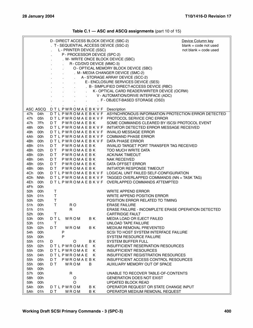
28 January 2004 T10/1416-D Revision 17
47h 04h D T L P W R O M A E B K V F ASYNCHRONOUS INFORMATION PROTECTION ERROR DETECTED47h 05h D T L P W R O M A E B K V F PROTOCOL SERVICE CRC ERROR47h 7Fh D T P W R O M A E B K SOME COMMANDS CLEARED BY ISCSI PROTOCOL EVENT48h 00h D T L P W R O M A E B K V F INITIATOR DETECTED ERROR MESSAGE RECEIVED49h 00h D T L P W R O M A E B K V F INVALID MESSAGE ERROR4Ah 00h D T L P W R O M A E B K V F COMMAND PHASE ERROR4Bh 00h D T L P W R O M A E B K V F DATA PHASE ERROR4Bh 01h D T P W R O M A E B K INVALID TARGET PORT TRANSFER TAG RECEIVED4Bh 02h D T P W R O M A E B K TOO MUCH WRITE DATA4Bh 03h D T P W R O M A E B K ACK/NAK TIMEOUT4Bh 04h D T P W R O M A E B K NAK RECEIVED4Bh 05h D T P W R O M A E B K DATA OFFSET ERROR4Bh 06h D T P W R O M A E B K INITIATOR RESPONSE TIMEOUT4Ch 00h D T L P W R O M A E B K V F LOGICAL UNIT FAILED SELF-CONFIGURATION4Dh NNh D T L P W R O M A E B K V F TAGGED OVERLAPPED COMMANDS (NN = TASK TAG)4Eh 00h D T L P W R O M A E B K V F OVERLAPPED COMMANDS ATTEMPTED4Fh 00h50h 00h T WRITE APPEND ERROR50h 01h T WRITE APPEND POSITION ERROR50h 02h T POSITION ERROR RELATED TO TIMING51h 00h T R O ERASE FAILURE51h 01h R ERASE FAILURE - INCOMPLETE ERASE OPERATION DETECTED52h 00h T CARTRIDGE FAULT53h 00h D T L W R O M B K MEDIA LOAD OR EJECT FAILED53h 01h T UNLOAD TAPE FAILURE53h 02h D T W R O M B K MEDIUM REMOVAL PREVENTED54h 00h P SCSI TO HOST SYSTEM INTERFACE FAILURE55h 00h P SYSTEM RESOURCE FAILURE55h 01h D O B K SYSTEM BUFFER FULL55h 02h D T L P W R O M A E K INSUFFICIENT RESERVATION RESOURCES55h 03h D T L P W R O M A E K INSUFFICIENT RESOURCES55h 04h D T L P W R O M A E K INSUFFICIENT REGISTRATION RESOURCES55h 05h D T P W R O M A E B K INSUFFICIENT ACCESS CONTROL RESOURCES55h 06h D T W R O M B AUXILIARY MEMORY OUT OF SPACE56h 00h57h 00h R UNABLE TO RECOVER TABLE-OF-CONTENTS58h 00h O GENERATION DOES NOT EXIST59h 00h O UPDATED BLOCK READ5Ah 00h D T L P W R O M B K OPERATOR REQUEST OR STATE CHANGE INPUT5Ah 01h D T W R O M B K OPERATOR MEDIUM REMOVAL REQUEST
Table C.1 — ASC and ASCQ assignments (part 10 of 15)
D - DIRECT ACCESS BLOCK DEVICE (SBC-2) Device Column key. T - SEQUENTIAL ACCESS DEVICE (SSC-2) blank = code not used. L - PRINTER DEVICE (SSC) not blank = code used. P - PROCESSOR DEVICE (SPC-2). . W- WRITE ONCE BLOCK DEVICE (SBC). . R - CD/DVD DEVICE (MMC-3). . O- OPTICAL MEMORY BLOCK DEVICE (SBC). . . M- MEDIA CHANGER DEVICE (SMC-2). . . A - STORAGE ARRAY DEVICE (SCC-2). . . E - ENCLOSURE SERVICES DEVICE (SES). . . . B - SIMPLIFIED DIRECT-ACCESS DEVICE (RBC). . . . K - OPTICAL CARD READER/WRITER DEVICE (OCRW). . . . V - AUTOMATION/DRIVE INTERFACE (ADC). . . . . F - OBJECT-BASED STORAGE (OSD). . . . .
ASC ASCQ D T L P W R O M A E B K V F Description
Working Draft SCSI Primary Commands - 3 (SPC-3) 400
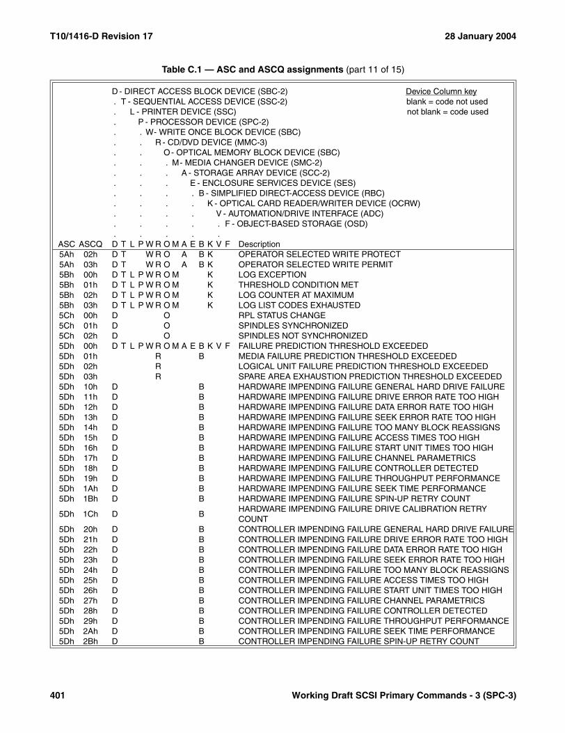
T10/1416-D Revision 17 28 January 2004
5Ah 02h D T W R O A B K OPERATOR SELECTED WRITE PROTECT5Ah 03h D T W R O A B K OPERATOR SELECTED WRITE PERMIT5Bh 00h D T L P W R O M K LOG EXCEPTION5Bh 01h D T L P W R O M K THRESHOLD CONDITION MET5Bh 02h D T L P W R O M K LOG COUNTER AT MAXIMUM5Bh 03h D T L P W R O M K LOG LIST CODES EXHAUSTED5Ch 00h D O RPL STATUS CHANGE5Ch 01h D O SPINDLES SYNCHRONIZED5Ch 02h D O SPINDLES NOT SYNCHRONIZED5Dh 00h D T L P W R O M A E B K V F FAILURE PREDICTION THRESHOLD EXCEEDED5Dh 01h R B MEDIA FAILURE PREDICTION THRESHOLD EXCEEDED5Dh 02h R LOGICAL UNIT FAILURE PREDICTION THRESHOLD EXCEEDED5Dh 03h R SPARE AREA EXHAUSTION PREDICTION THRESHOLD EXCEEDED5Dh 10h D B HARDWARE IMPENDING FAILURE GENERAL HARD DRIVE FAILURE5Dh 11h D B HARDWARE IMPENDING FAILURE DRIVE ERROR RATE TOO HIGH5Dh 12h D B HARDWARE IMPENDING FAILURE DATA ERROR RATE TOO HIGH5Dh 13h D B HARDWARE IMPENDING FAILURE SEEK ERROR RATE TOO HIGH5Dh 14h D B HARDWARE IMPENDING FAILURE TOO MANY BLOCK REASSIGNS5Dh 15h D B HARDWARE IMPENDING FAILURE ACCESS TIMES TOO HIGH5Dh 16h D B HARDWARE IMPENDING FAILURE START UNIT TIMES TOO HIGH5Dh 17h D B HARDWARE IMPENDING FAILURE CHANNEL PARAMETRICS5Dh 18h D B HARDWARE IMPENDING FAILURE CONTROLLER DETECTED5Dh 19h D B HARDWARE IMPENDING FAILURE THROUGHPUT PERFORMANCE5Dh 1Ah D B HARDWARE IMPENDING FAILURE SEEK TIME PERFORMANCE5Dh 1Bh D B HARDWARE IMPENDING FAILURE SPIN-UP RETRY COUNT
5Dh 1Ch D BHARDWARE IMPENDING FAILURE DRIVE CALIBRATION RETRY COUNT
5Dh 20h D B CONTROLLER IMPENDING FAILURE GENERAL HARD DRIVE FAILURE5Dh 21h D B CONTROLLER IMPENDING FAILURE DRIVE ERROR RATE TOO HIGH5Dh 22h D B CONTROLLER IMPENDING FAILURE DATA ERROR RATE TOO HIGH5Dh 23h D B CONTROLLER IMPENDING FAILURE SEEK ERROR RATE TOO HIGH5Dh 24h D B CONTROLLER IMPENDING FAILURE TOO MANY BLOCK REASSIGNS5Dh 25h D B CONTROLLER IMPENDING FAILURE ACCESS TIMES TOO HIGH5Dh 26h D B CONTROLLER IMPENDING FAILURE START UNIT TIMES TOO HIGH5Dh 27h D B CONTROLLER IMPENDING FAILURE CHANNEL PARAMETRICS5Dh 28h D B CONTROLLER IMPENDING FAILURE CONTROLLER DETECTED5Dh 29h D B CONTROLLER IMPENDING FAILURE THROUGHPUT PERFORMANCE5Dh 2Ah D B CONTROLLER IMPENDING FAILURE SEEK TIME PERFORMANCE5Dh 2Bh D B CONTROLLER IMPENDING FAILURE SPIN-UP RETRY COUNT
Table C.1 — ASC and ASCQ assignments (part 11 of 15)
D - DIRECT ACCESS BLOCK DEVICE (SBC-2) Device Column key. T - SEQUENTIAL ACCESS DEVICE (SSC-2) blank = code not used. L - PRINTER DEVICE (SSC) not blank = code used. P - PROCESSOR DEVICE (SPC-2). . W- WRITE ONCE BLOCK DEVICE (SBC). . R - CD/DVD DEVICE (MMC-3). . O- OPTICAL MEMORY BLOCK DEVICE (SBC). . . M- MEDIA CHANGER DEVICE (SMC-2). . . A - STORAGE ARRAY DEVICE (SCC-2). . . E - ENCLOSURE SERVICES DEVICE (SES). . . . B - SIMPLIFIED DIRECT-ACCESS DEVICE (RBC). . . . K - OPTICAL CARD READER/WRITER DEVICE (OCRW). . . . V - AUTOMATION/DRIVE INTERFACE (ADC). . . . . F - OBJECT-BASED STORAGE (OSD). . . . .
ASC ASCQ D T L P W R O M A E B K V F Description
401 Working Draft SCSI Primary Commands - 3 (SPC-3)
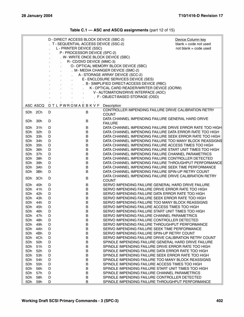
28 January 2004 T10/1416-D Revision 17
5Dh 2Ch D BCONTROLLER IMPENDING FAILURE DRIVE CALIBRATION RETRY COUNT
5Dh 30h D BDATA CHANNEL IMPENDING FAILURE GENERAL HARD DRIVE FAILURE
5Dh 31h D B DATA CHANNEL IMPENDING FAILURE DRIVE ERROR RATE TOO HIGH5Dh 32h D B DATA CHANNEL IMPENDING FAILURE DATA ERROR RATE TOO HIGH5Dh 33h D B DATA CHANNEL IMPENDING FAILURE SEEK ERROR RATE TOO HIGH5Dh 34h D B DATA CHANNEL IMPENDING FAILURE TOO MANY BLOCK REASSIGNS5Dh 35h D B DATA CHANNEL IMPENDING FAILURE ACCESS TIMES TOO HIGH5Dh 36h D B DATA CHANNEL IMPENDING FAILURE START UNIT TIMES TOO HIGH5Dh 37h D B DATA CHANNEL IMPENDING FAILURE CHANNEL PARAMETRICS5Dh 38h D B DATA CHANNEL IMPENDING FAILURE CONTROLLER DETECTED5Dh 39h D B DATA CHANNEL IMPENDING FAILURE THROUGHPUT PERFORMANCE5Dh 3Ah D B DATA CHANNEL IMPENDING FAILURE SEEK TIME PERFORMANCE5Dh 3Bh D B DATA CHANNEL IMPENDING FAILURE SPIN-UP RETRY COUNT
5Dh 3Ch D BDATA CHANNEL IMPENDING FAILURE DRIVE CALIBRATION RETRY COUNT
5Dh 40h D B SERVO IMPENDING FAILURE GENERAL HARD DRIVE FAILURE5Dh 41h D B SERVO IMPENDING FAILURE DRIVE ERROR RATE TOO HIGH5Dh 42h D B SERVO IMPENDING FAILURE DATA ERROR RATE TOO HIGH5Dh 43h D B SERVO IMPENDING FAILURE SEEK ERROR RATE TOO HIGH5Dh 44h D B SERVO IMPENDING FAILURE TOO MANY BLOCK REASSIGNS5Dh 45h D B SERVO IMPENDING FAILURE ACCESS TIMES TOO HIGH5Dh 46h D B SERVO IMPENDING FAILURE START UNIT TIMES TOO HIGH5Dh 47h D B SERVO IMPENDING FAILURE CHANNEL PARAMETRICS5Dh 48h D B SERVO IMPENDING FAILURE CONTROLLER DETECTED5Dh 49h D B SERVO IMPENDING FAILURE THROUGHPUT PERFORMANCE5Dh 4Ah D B SERVO IMPENDING FAILURE SEEK TIME PERFORMANCE5Dh 4Bh D B SERVO IMPENDING FAILURE SPIN-UP RETRY COUNT5Dh 4Ch D B SERVO IMPENDING FAILURE DRIVE CALIBRATION RETRY COUNT5Dh 50h D B SPINDLE IMPENDING FAILURE GENERAL HARD DRIVE FAILURE5Dh 51h D B SPINDLE IMPENDING FAILURE DRIVE ERROR RATE TOO HIGH5Dh 52h D B SPINDLE IMPENDING FAILURE DATA ERROR RATE TOO HIGH5Dh 53h D B SPINDLE IMPENDING FAILURE SEEK ERROR RATE TOO HIGH5Dh 54h D B SPINDLE IMPENDING FAILURE TOO MANY BLOCK REASSIGNS5Dh 55h D B SPINDLE IMPENDING FAILURE ACCESS TIMES TOO HIGH5Dh 56h D B SPINDLE IMPENDING FAILURE START UNIT TIMES TOO HIGH5Dh 57h D B SPINDLE IMPENDING FAILURE CHANNEL PARAMETRICS5Dh 58h D B SPINDLE IMPENDING FAILURE CONTROLLER DETECTED5Dh 59h D B SPINDLE IMPENDING FAILURE THROUGHPUT PERFORMANCE
Table C.1 — ASC and ASCQ assignments (part 12 of 15)
D - DIRECT ACCESS BLOCK DEVICE (SBC-2) Device Column key. T - SEQUENTIAL ACCESS DEVICE (SSC-2) blank = code not used. L - PRINTER DEVICE (SSC) not blank = code used. P - PROCESSOR DEVICE (SPC-2). . W- WRITE ONCE BLOCK DEVICE (SBC). . R - CD/DVD DEVICE (MMC-3). . O- OPTICAL MEMORY BLOCK DEVICE (SBC). . . M- MEDIA CHANGER DEVICE (SMC-2). . . A - STORAGE ARRAY DEVICE (SCC-2). . . E - ENCLOSURE SERVICES DEVICE (SES). . . . B - SIMPLIFIED DIRECT-ACCESS DEVICE (RBC). . . . K - OPTICAL CARD READER/WRITER DEVICE (OCRW). . . . V - AUTOMATION/DRIVE INTERFACE (ADC). . . . . F - OBJECT-BASED STORAGE (OSD). . . . .
ASC ASCQ D T L P W R O M A E B K V F Description
Working Draft SCSI Primary Commands - 3 (SPC-3) 402

T10/1416-D Revision 17 28 January 2004
5Dh 5Ah D B SPINDLE IMPENDING FAILURE SEEK TIME PERFORMANCE5Dh 5Bh D B SPINDLE IMPENDING FAILURE SPIN-UP RETRY COUNT5Dh 5Ch D B SPINDLE IMPENDING FAILURE DRIVE CALIBRATION RETRY COUNT5Dh 60h D B FIRMWARE IMPENDING FAILURE GENERAL HARD DRIVE FAILURE5Dh 61h D B FIRMWARE IMPENDING FAILURE DRIVE ERROR RATE TOO HIGH5Dh 62h D B FIRMWARE IMPENDING FAILURE DATA ERROR RATE TOO HIGH5Dh 63h D B FIRMWARE IMPENDING FAILURE SEEK ERROR RATE TOO HIGH5Dh 64h D B FIRMWARE IMPENDING FAILURE TOO MANY BLOCK REASSIGNS5Dh 65h D B FIRMWARE IMPENDING FAILURE ACCESS TIMES TOO HIGH5Dh 66h D B FIRMWARE IMPENDING FAILURE START UNIT TIMES TOO HIGH5Dh 67h D B FIRMWARE IMPENDING FAILURE CHANNEL PARAMETRICS5Dh 68h D B FIRMWARE IMPENDING FAILURE CONTROLLER DETECTED5Dh 69h D B FIRMWARE IMPENDING FAILURE THROUGHPUT PERFORMANCE5Dh 6Ah D B FIRMWARE IMPENDING FAILURE SEEK TIME PERFORMANCE5Dh 6Bh D B FIRMWARE IMPENDING FAILURE SPIN-UP RETRY COUNT5Dh 6Ch D B FIRMWARE IMPENDING FAILURE DRIVE CALIBRATION RETRY COUNT5Dh FFh D T L P W R O M A E B K V F FAILURE PREDICTION THRESHOLD EXCEEDED (FALSE)5Eh 00h D T L P W R O A K LOW POWER CONDITION ON5Eh 01h D T L P W R O A K IDLE CONDITION ACTIVATED BY TIMER5Eh 02h D T L P W R O A K STANDBY CONDITION ACTIVATED BY TIMER5Eh 03h D T L P W R O A K IDLE CONDITION ACTIVATED BY COMMAND5Eh 04h D T L P W R O A K STANDBY CONDITION ACTIVATED BY COMMAND5Eh 41h B POWER STATE CHANGE TO ACTIVE5Eh 42h B POWER STATE CHANGE TO IDLE5Eh 43h B POWER STATE CHANGE TO STANDBY5Eh 45h B POWER STATE CHANGE TO SLEEP5Eh 47h B K POWER STATE CHANGE TO DEVICE CONTROL5Fh 00h60h 00h LAMP FAILURE61h 00h VIDEO ACQUISITION ERROR61h 01h UNABLE TO ACQUIRE VIDEO61h 02h OUT OF FOCUS62h 00h SCAN HEAD POSITIONING ERROR63h 00h R END OF USER AREA ENCOUNTERED ON THIS TRACK63h 01h R PACKET DOES NOT FIT IN AVAILABLE SPACE64h 00h R ILLEGAL MODE FOR THIS TRACK64h 01h R INVALID PACKET SIZE65h 00h D T L P W R O M A E B K V F VOLTAGE FAULT66h 00h AUTOMATIC DOCUMENT FEEDER COVER UP66h 01h AUTOMATIC DOCUMENT FEEDER LIFT UP
Table C.1 — ASC and ASCQ assignments (part 13 of 15)
D - DIRECT ACCESS BLOCK DEVICE (SBC-2) Device Column key. T - SEQUENTIAL ACCESS DEVICE (SSC-2) blank = code not used. L - PRINTER DEVICE (SSC) not blank = code used. P - PROCESSOR DEVICE (SPC-2). . W- WRITE ONCE BLOCK DEVICE (SBC). . R - CD/DVD DEVICE (MMC-3). . O- OPTICAL MEMORY BLOCK DEVICE (SBC). . . M- MEDIA CHANGER DEVICE (SMC-2). . . A - STORAGE ARRAY DEVICE (SCC-2). . . E - ENCLOSURE SERVICES DEVICE (SES). . . . B - SIMPLIFIED DIRECT-ACCESS DEVICE (RBC). . . . K - OPTICAL CARD READER/WRITER DEVICE (OCRW). . . . V - AUTOMATION/DRIVE INTERFACE (ADC). . . . . F - OBJECT-BASED STORAGE (OSD). . . . .
ASC ASCQ D T L P W R O M A E B K V F Description
403 Working Draft SCSI Primary Commands - 3 (SPC-3)

28 January 2004 T10/1416-D Revision 17
66h 02h DOCUMENT JAM IN AUTOMATIC DOCUMENT FEEDER66h 03h DOCUMENT MISS FEED AUTOMATIC IN DOCUMENT FEEDER67h 00h A CONFIGURATION FAILURE67h 01h A CONFIGURATION OF INCAPABLE LOGICAL UNITS FAILED67h 02h A ADD LOGICAL UNIT FAILED67h 03h A MODIFICATION OF LOGICAL UNIT FAILED67h 04h A EXCHANGE OF LOGICAL UNIT FAILED67h 05h A REMOVE OF LOGICAL UNIT FAILED67h 06h A ATTACHMENT OF LOGICAL UNIT FAILED67h 07h A CREATION OF LOGICAL UNIT FAILED67h 08h A ASSIGN FAILURE OCCURRED67h 09h A MULTIPLY ASSIGNED LOGICAL UNIT67h 0Ah D T L P W R O M A E B K V F SET TARGET PORT GROUPS COMMAND FAILED68h 00h A LOGICAL UNIT NOT CONFIGURED69h 00h A DATA LOSS ON LOGICAL UNIT69h 01h A MULTIPLE LOGICAL UNIT FAILURES69h 02h A PARITY/DATA MISMATCH6Ah 00h A INFORMATIONAL, REFER TO LOG6Bh 00h A STATE CHANGE HAS OCCURRED6Bh 01h A REDUNDANCY LEVEL GOT BETTER6Bh 02h A REDUNDANCY LEVEL GOT WORSE6Ch 00h A REBUILD FAILURE OCCURRED6Dh 00h A RECALCULATE FAILURE OCCURRED6Eh 00h A COMMAND TO LOGICAL UNIT FAILED
6Fh 00h RCOPY PROTECTION KEY EXCHANGE FAILURE - AUTHENTICATION FAILURE
6Fh 01h R COPY PROTECTION KEY EXCHANGE FAILURE - KEY NOT PRESENT
6Fh 02h RCOPY PROTECTION KEY EXCHANGE FAILURE - KEY NOT ESTABLISHED
6Fh 03h R READ OF SCRAMBLED SECTOR WITHOUT AUTHENTICATION6Fh 04h R MEDIA REGION CODE IS MISMATCHED TO LOGICAL UNIT REGION
6Fh 05h RDRIVE REGION MUST BE PERMANENT/REGION RESET COUNT ERROR
70h NNh T DECOMPRESSION EXCEPTION SHORT ALGORITHM ID OF NN71h 00h T DECOMPRESSION EXCEPTION LONG ALGORITHM ID72h 00h R SESSION FIXATION ERROR72h 01h R SESSION FIXATION ERROR WRITING LEAD-IN72h 02h R SESSION FIXATION ERROR WRITING LEAD-OUT72h 03h R SESSION FIXATION ERROR - INCOMPLETE TRACK IN SESSION72h 04h R EMPTY OR PARTIALLY WRITTEN RESERVED TRACK
Table C.1 — ASC and ASCQ assignments (part 14 of 15)
D - DIRECT ACCESS BLOCK DEVICE (SBC-2) Device Column key. T - SEQUENTIAL ACCESS DEVICE (SSC-2) blank = code not used. L - PRINTER DEVICE (SSC) not blank = code used. P - PROCESSOR DEVICE (SPC-2). . W- WRITE ONCE BLOCK DEVICE (SBC). . R - CD/DVD DEVICE (MMC-3). . O- OPTICAL MEMORY BLOCK DEVICE (SBC). . . M- MEDIA CHANGER DEVICE (SMC-2). . . A - STORAGE ARRAY DEVICE (SCC-2). . . E - ENCLOSURE SERVICES DEVICE (SES). . . . B - SIMPLIFIED DIRECT-ACCESS DEVICE (RBC). . . . K - OPTICAL CARD READER/WRITER DEVICE (OCRW). . . . V - AUTOMATION/DRIVE INTERFACE (ADC). . . . . F - OBJECT-BASED STORAGE (OSD). . . . .
ASC ASCQ D T L P W R O M A E B K V F Description
Working Draft SCSI Primary Commands - 3 (SPC-3) 404

T10/1416-D Revision 17 28 January 2004
72h 05h R NO MORE TRACK RESERVATIONS ALLOWED73h 00h R CD CONTROL ERROR73h 01h R POWER CALIBRATION AREA ALMOST FULL73h 02h R POWER CALIBRATION AREA IS FULL73h 03h R POWER CALIBRATION AREA ERROR73h 04h R PROGRAM MEMORY AREA UPDATE FAILURE73h 05h R PROGRAM MEMORY AREA IS FULL73h 06h R RMA/PMA IS ALMOST FULL74h 00h75h 00h76h 00h77h 00h78h 00h79h 00h7Ah 00h7Bh 00h7Ch 00h7Dh 00h7Eh 00h7Fh 00h
80h xxh \Through > vendor specific.
FFh xxh /
xxh 80h \Through > vendor specific QUALIFICATION OF STANDARD ASC.
xxh FFh /ALL CODES NOT SHOWN ARE RESERVED.
Table C.1 — ASC and ASCQ assignments (part 15 of 15)
D - DIRECT ACCESS BLOCK DEVICE (SBC-2) Device Column key. T - SEQUENTIAL ACCESS DEVICE (SSC-2) blank = code not used. L - PRINTER DEVICE (SSC) not blank = code used. P - PROCESSOR DEVICE (SPC-2). . W- WRITE ONCE BLOCK DEVICE (SBC). . R - CD/DVD DEVICE (MMC-3). . O- OPTICAL MEMORY BLOCK DEVICE (SBC). . . M- MEDIA CHANGER DEVICE (SMC-2). . . A - STORAGE ARRAY DEVICE (SCC-2). . . E - ENCLOSURE SERVICES DEVICE (SES). . . . B - SIMPLIFIED DIRECT-ACCESS DEVICE (RBC). . . . K - OPTICAL CARD READER/WRITER DEVICE (OCRW). . . . V - AUTOMATION/DRIVE INTERFACE (ADC). . . . . F - OBJECT-BASED STORAGE (OSD). . . . .
ASC ASCQ D T L P W R O M A E B K V F Description
405 Working Draft SCSI Primary Commands - 3 (SPC-3)
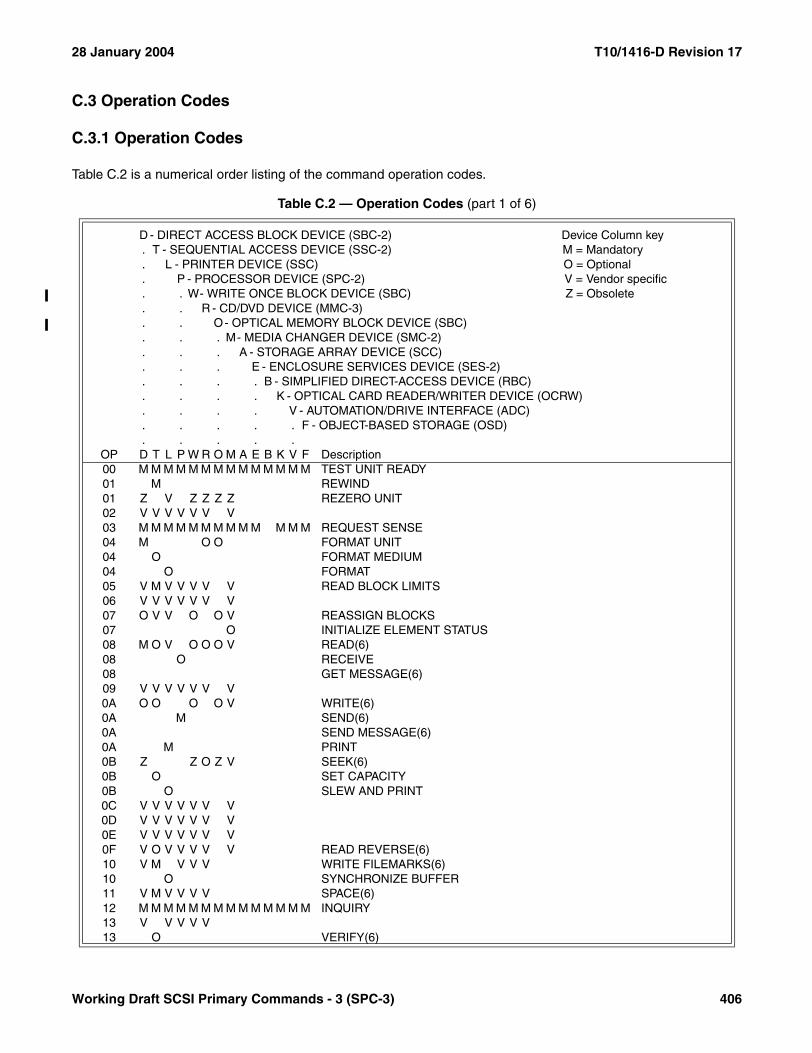
28 January 2004 T10/1416-D Revision 17
C.3 Operation Codes
C.3.1 Operation Codes
Table C.2 is a numerical order listing of the command operation codes.
Table C.2 — Operation Codes (part 1 of 6)
D - DIRECT ACCESS BLOCK DEVICE (SBC-2) Device Column key. T - SEQUENTIAL ACCESS DEVICE (SSC-2) M = Mandatory. L - PRINTER DEVICE (SSC) O = Optional. P - PROCESSOR DEVICE (SPC-2) V = Vendor specific. . W- WRITE ONCE BLOCK DEVICE (SBC) Z = Obsolete. . R - CD/DVD DEVICE (MMC-3). . O- OPTICAL MEMORY BLOCK DEVICE (SBC). . . M- MEDIA CHANGER DEVICE (SMC-2). . . A - STORAGE ARRAY DEVICE (SCC). . . E - ENCLOSURE SERVICES DEVICE (SES-2). . . . B - SIMPLIFIED DIRECT-ACCESS DEVICE (RBC). . . . K - OPTICAL CARD READER/WRITER DEVICE (OCRW). . . . V - AUTOMATION/DRIVE INTERFACE (ADC). . . . . F - OBJECT-BASED STORAGE (OSD). . . . .
OP D T L P W R O M A E B K V F Description00 M M M M M M M M M M M M M M TEST UNIT READY01 M REWIND01 Z V Z Z Z Z REZERO UNIT02 V V V V V V V03 M M M M M M M M M M M M M REQUEST SENSE04 M O O FORMAT UNIT04 O FORMAT MEDIUM04 O FORMAT05 V M V V V V V READ BLOCK LIMITS06 V V V V V V V07 O V V O O V REASSIGN BLOCKS07 O INITIALIZE ELEMENT STATUS08 M O V O O O V READ(6)08 O RECEIVE08 GET MESSAGE(6)09 V V V V V V V0A O O O O V WRITE(6)0A M SEND(6)0A SEND MESSAGE(6)0A M PRINT0B Z Z O Z V SEEK(6)0B O SET CAPACITY0B O SLEW AND PRINT0C V V V V V V V0D V V V V V V V0E V V V V V V V0F V O V V V V V READ REVERSE(6)10 V M V V V WRITE FILEMARKS(6)10 O SYNCHRONIZE BUFFER11 V M V V V V SPACE(6)12 M M M M M M M M M M M M M M INQUIRY13 V V V V V13 O VERIFY(6)
Working Draft SCSI Primary Commands - 3 (SPC-3) 406

T10/1416-D Revision 17 28 January 2004
14 V O O V V V RECOVER BUFFERED DATA15 O M O O O O O O O O O MODE SELECT(6)16 Z M M Z Z O Z O O Z O RESERVE(6)16 Z RESERVE ELEMENT(6)17 Z M M Z Z O Z O O Z O RELEASE(6)17 Z RELEASE ELEMENT(6)18 Z Z Z Z Z Z Z Z COPY19 V M V V V V ERASE(6)1A O M O O O O O O O O O MODE SENSE(6)1B O O M O O M O O START STOP UNIT1B O M LOAD UNLOAD1B SCAN1B O STOP PRINT1C O O O O O O O O O M O O O RECEIVE DIAGNOSTIC RESULTS1D M M M M M M M M O M M M M SEND DIAGNOSTIC1E O O O M O O O O PREVENT ALLOW MEDIUM REMOVAL1F20 V V V V V21 V V V V V22 V V V V V23 V V V V23 O READ FORMAT CAPACITIES24 V V V SET WINDOW25 M M M READ CAPACITY(10)25 M READ CAPACITY25 M READ CARD CAPACITY25 GET WINDOW26 V V V27 V V V28 M M M M M M READ(10)28 GET MESSAGE(10)29 V V V O READ GENERATION2A O M M M M O WRITE(10)2A SEND(10)2A SEND MESSAGE(10)2B O O M O O SEEK(10)2B O LOCATE(10)2B O POSITION TO ELEMENT2C V O O ERASE(10)2D O READ UPDATED BLOCK
Table C.2 — Operation Codes (part 2 of 6)
D - DIRECT ACCESS BLOCK DEVICE (SBC-2) Device Column key. T - SEQUENTIAL ACCESS DEVICE (SSC-2) M = Mandatory. L - PRINTER DEVICE (SSC) O = Optional. P - PROCESSOR DEVICE (SPC-2) V = Vendor specific. . W- WRITE ONCE BLOCK DEVICE (SBC) Z = Obsolete. . R - CD/DVD DEVICE (MMC-3). . O- OPTICAL MEMORY BLOCK DEVICE (SBC). . . M- MEDIA CHANGER DEVICE (SMC-2). . . A - STORAGE ARRAY DEVICE (SCC). . . E - ENCLOSURE SERVICES DEVICE (SES-2). . . . B - SIMPLIFIED DIRECT-ACCESS DEVICE (RBC). . . . K - OPTICAL CARD READER/WRITER DEVICE (OCRW). . . . V - AUTOMATION/DRIVE INTERFACE (ADC). . . . . F - OBJECT-BASED STORAGE (OSD). . . . .
OP D T L P W R O M A E B K V F Description
407 Working Draft SCSI Primary Commands - 3 (SPC-3)

28 January 2004 T10/1416-D Revision 17
2D V2E O O O O M O WRITE AND VERIFY(10)2F O O O O VERIFY(10)30 Z Z Z Z SEARCH DATA HIGH(10)31 Z Z Z Z SEARCH DATA EQUAL(10)31 OBJECT POSITION32 Z Z Z Z SEARCH DATA LOW(10)33 Z Z Z Z SET LIMITS(10)34 O O O O O PRE-FETCH(10)34 M READ POSITION34 GET DATA BUFFER STATUS35 O O M O M O SYNCHRONIZE CACHE(10)36 O O O O O LOCK UNLOCK CACHE(10)37 O O READ DEFECT DATA(10)37 O INITIALIZE ELEMENT STATUS WITH RANGE38 O O O MEDIUM SCAN39 Z Z Z Z Z Z Z Z COMPARE3A Z Z Z Z Z Z Z Z COPY AND VERIFY3B O O O O O O O O O O M O O O WRITE BUFFER3C O O O O O O O O O O O O O READ BUFFER3D O UPDATE BLOCK3E O O O O READ LONG3F O O O WRITE LONG40 Z Z Z Z Z Z Z Z CHANGE DEFINITION41 O WRITE SAME(10)42 M READ SUB-CHANNEL43 M READ TOC/PMA/ATIP44 M M REPORT DENSITY SUPPORT44 M READ HEADER45 O PLAY AUDIO(10)46 O GET CONFIGURATION47 O PLAY AUDIO MSF48 Z PLAY AUDIO TRACK INDEX49 Z PLAY TRACK RELATIVE(10)4A O GET EVENT STATUS NOTIFICATION4B O PAUSE/RESUME4C O O O O O O O O O O O O O LOG SELECT4D O O O O O O O O O O O M O LOG SENSE4E O STOP PLAY/SCAN4F
Table C.2 — Operation Codes (part 3 of 6)
D - DIRECT ACCESS BLOCK DEVICE (SBC-2) Device Column key. T - SEQUENTIAL ACCESS DEVICE (SSC-2) M = Mandatory. L - PRINTER DEVICE (SSC) O = Optional. P - PROCESSOR DEVICE (SPC-2) V = Vendor specific. . W- WRITE ONCE BLOCK DEVICE (SBC) Z = Obsolete. . R - CD/DVD DEVICE (MMC-3). . O- OPTICAL MEMORY BLOCK DEVICE (SBC). . . M- MEDIA CHANGER DEVICE (SMC-2). . . A - STORAGE ARRAY DEVICE (SCC). . . E - ENCLOSURE SERVICES DEVICE (SES-2). . . . B - SIMPLIFIED DIRECT-ACCESS DEVICE (RBC). . . . K - OPTICAL CARD READER/WRITER DEVICE (OCRW). . . . V - AUTOMATION/DRIVE INTERFACE (ADC). . . . . F - OBJECT-BASED STORAGE (OSD). . . . .
OP D T L P W R O M A E B K V F Description
Working Draft SCSI Primary Commands - 3 (SPC-3) 408
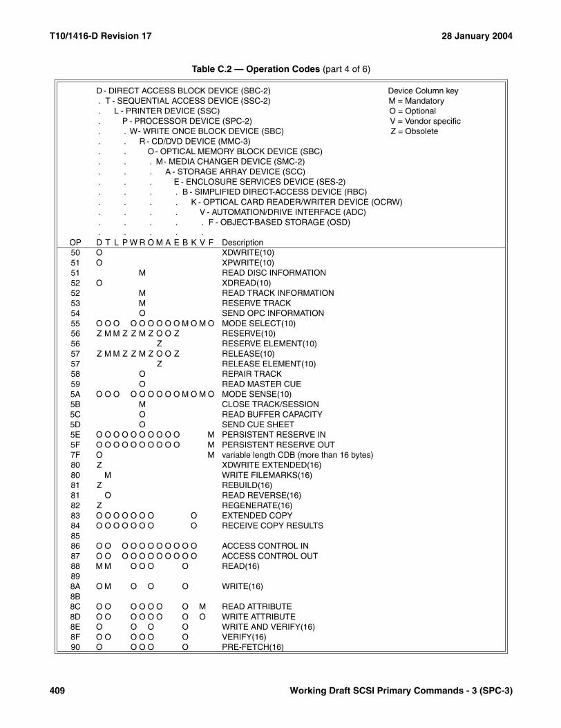
T10/1416-D Revision 17 28 January 2004
50 O XDWRITE(10)51 O XPWRITE(10)51 M READ DISC INFORMATION52 O XDREAD(10)52 M READ TRACK INFORMATION53 M RESERVE TRACK54 O SEND OPC INFORMATION55 O O O O O O O O O M O M O MODE SELECT(10)56 Z M M Z Z M Z O O Z RESERVE(10)56 Z RESERVE ELEMENT(10)57 Z M M Z Z M Z O O Z RELEASE(10)57 Z RELEASE ELEMENT(10)58 O REPAIR TRACK59 O READ MASTER CUE5A O O O O O O O O O M O M O MODE SENSE(10)5B M CLOSE TRACK/SESSION5C O READ BUFFER CAPACITY5D O SEND CUE SHEET5E O O O O O O O O O O M PERSISTENT RESERVE IN5F O O O O O O O O O O M PERSISTENT RESERVE OUT7F O M variable length CDB (more than 16 bytes)80 Z XDWRITE EXTENDED(16)80 M WRITE FILEMARKS(16)81 Z REBUILD(16)81 O READ REVERSE(16)82 Z REGENERATE(16)83 O O O O O O O O EXTENDED COPY84 O O O O O O O O RECEIVE COPY RESULTS8586 O O O O O O O O O O O ACCESS CONTROL IN87 O O O O O O O O O O O ACCESS CONTROL OUT88 M M O O O O READ(16)898A O M O O O WRITE(16)8B8C O O O O O O O M READ ATTRIBUTE8D O O O O O O O O WRITE ATTRIBUTE8E O O O O WRITE AND VERIFY(16)8F O O O O O O VERIFY(16)90 O O O O O PRE-FETCH(16)
Table C.2 — Operation Codes (part 4 of 6)
D - DIRECT ACCESS BLOCK DEVICE (SBC-2) Device Column key. T - SEQUENTIAL ACCESS DEVICE (SSC-2) M = Mandatory. L - PRINTER DEVICE (SSC) O = Optional. P - PROCESSOR DEVICE (SPC-2) V = Vendor specific. . W- WRITE ONCE BLOCK DEVICE (SBC) Z = Obsolete. . R - CD/DVD DEVICE (MMC-3). . O- OPTICAL MEMORY BLOCK DEVICE (SBC). . . M- MEDIA CHANGER DEVICE (SMC-2). . . A - STORAGE ARRAY DEVICE (SCC). . . E - ENCLOSURE SERVICES DEVICE (SES-2). . . . B - SIMPLIFIED DIRECT-ACCESS DEVICE (RBC). . . . K - OPTICAL CARD READER/WRITER DEVICE (OCRW). . . . V - AUTOMATION/DRIVE INTERFACE (ADC). . . . . F - OBJECT-BASED STORAGE (OSD). . . . .
OP D T L P W R O M A E B K V F Description
409 Working Draft SCSI Primary Commands - 3 (SPC-3)

28 January 2004 T10/1416-D Revision 17
91 O O O O O SYNCHRONIZE CACHE(16)91 O SPACE(16)92 O O O O LOCK UNLOCK CACHE(16)92 O LOCATE(16)93 O WRITE SAME(16)93 M ERASE(16)94 [usage proposed by SCSI Socket Services project]95 [usage proposed by SCSI Socket Services project]96 [usage proposed by SCSI Socket Services project]97 [usage proposed by SCSI Socket Services project]98999A9B9C9D9E SERVICE ACTION IN(16)9F SERVICE ACTION OUT(16)A0 O M O O O O O O M O O M O REPORT LUNSA1 O BLANKA2 O SEND EVENTA3 O O O O O O M O O O MAINTENANCE (IN)A3 O SEND KEYA4 O O O O O O O O O O MAINTENANCE (OUT)A4 O REPORT KEYA5 O M MOVE MEDIUMA5 O PLAY AUDIO(12)A6 O EXCHANGE MEDIUMA6 O LOAD/UNLOAD C/DVDA7 O O O O MOVE MEDIUM ATTACHEDA7 O SET READ AHEADA8 O O M O READ(12)A8 GET MESSAGE(12)A9 Z PLAY TRACK RELATIVE(12)A9 SERVICE ACTION OUT(12)AA O O O WRITE(12)AA SEND MESSAGE(12)AB SERVICE ACTION IN(12)AC O ERASE(12)AC O GET PERFORMANCE
Table C.2 — Operation Codes (part 5 of 6)
D - DIRECT ACCESS BLOCK DEVICE (SBC-2) Device Column key. T - SEQUENTIAL ACCESS DEVICE (SSC-2) M = Mandatory. L - PRINTER DEVICE (SSC) O = Optional. P - PROCESSOR DEVICE (SPC-2) V = Vendor specific. . W- WRITE ONCE BLOCK DEVICE (SBC) Z = Obsolete. . R - CD/DVD DEVICE (MMC-3). . O- OPTICAL MEMORY BLOCK DEVICE (SBC). . . M- MEDIA CHANGER DEVICE (SMC-2). . . A - STORAGE ARRAY DEVICE (SCC). . . E - ENCLOSURE SERVICES DEVICE (SES-2). . . . B - SIMPLIFIED DIRECT-ACCESS DEVICE (RBC). . . . K - OPTICAL CARD READER/WRITER DEVICE (OCRW). . . . V - AUTOMATION/DRIVE INTERFACE (ADC). . . . . F - OBJECT-BASED STORAGE (OSD). . . . .
OP D T L P W R O M A E B K V F Description
Working Draft SCSI Primary Commands - 3 (SPC-3) 410

T10/1416-D Revision 17 28 January 2004
AD O READ DVD STRUCTUREAE O O O WRITE AND VERIFY(12)AF O O Z O VERIFY(12)B0 Z Z Z SEARCH DATA HIGH(12)B1 Z Z Z SEARCH DATA EQUAL(12)B2 Z Z Z SEARCH DATA LOW(12)B3 Z Z Z Z SET LIMITS(12)B4 O O O Z O READ ELEMENT STATUS ATTACHEDB5 O REQUEST VOLUME ELEMENT ADDRESSB6 O SEND VOLUME TAGB6 O SET STREAMINGB7 O O READ DEFECT DATA(12)B8 O Z M READ ELEMENT STATUSB9 M READ CD MSFBA O O O O M O REDUNDANCY GROUP (IN)BA O SCANBB O O O O O O REDUNDANCY GROUP (OUT)BB O SET CD-ROM SPEEDBC O O O O M O SPARE (IN)BC O PLAY CDBD O O O O O O SPARE (OUT)BD M MECHANISM STATUSBE O O O O M O VOLUME SET (IN)BE O READ CDBF O O O O O O VOLUME SET (OUT)BF O SEND DVD STRUCTURE
Table C.2 — Operation Codes (part 6 of 6)
D - DIRECT ACCESS BLOCK DEVICE (SBC-2) Device Column key. T - SEQUENTIAL ACCESS DEVICE (SSC-2) M = Mandatory. L - PRINTER DEVICE (SSC) O = Optional. P - PROCESSOR DEVICE (SPC-2) V = Vendor specific. . W- WRITE ONCE BLOCK DEVICE (SBC) Z = Obsolete. . R - CD/DVD DEVICE (MMC-3). . O- OPTICAL MEMORY BLOCK DEVICE (SBC). . . M- MEDIA CHANGER DEVICE (SMC-2). . . A - STORAGE ARRAY DEVICE (SCC). . . E - ENCLOSURE SERVICES DEVICE (SES-2). . . . B - SIMPLIFIED DIRECT-ACCESS DEVICE (RBC). . . . K - OPTICAL CARD READER/WRITER DEVICE (OCRW). . . . V - AUTOMATION/DRIVE INTERFACE (ADC). . . . . F - OBJECT-BASED STORAGE (OSD). . . . .
OP D T L P W R O M A E B K V F Description
411 Working Draft SCSI Primary Commands - 3 (SPC-3)

28 January 2004 T10/1416-D Revision 17
C.3.2 Additional operation codes for devices with the MCHNGR bit set
Table C.3 is a numerical order listing of the additional command operation codes used by devices that have theMChngr bit set in their standard INQUIRY data. The operation codes listed in table C.3 are in addition to theoperation codes listed in C.3.1 for the device type indicated by the standard INQUIRY data having the MCHNGR bitset.
C.3.3 Additional operation codes for devices with the EncServ bit set
Table C.4 is a numerical order listing of the additional command operation codes used by devices that have theEncServ bit set in their standard INQUIRY data. The operation codes listed in table C.4 are in addition to theoperation codes listed in C.3.1 for the device type indicated by the standard INQUIRY data having the EncServ bitset.
Table C.3 — Additional operation codes for devices with the MCHNGR bit set
D - DIRECT ACCESS BLOCK DEVICE (SBC-2) Device Column key. T - SEQUENTIAL ACCESS DEVICE (SSC-2) M = Mandatory. L - PRINTER DEVICE (SSC) O = Optional. P - PROCESSOR DEVICE (SPC-2) V = Vendor specific. . W- WRITE ONCE BLOCK DEVICE (SBC) Z = Obsolete. . R - CD/DVD DEVICE (MMC-3). . O- OPTICAL MEMORY BLOCK DEVICE (SBC). . . A - STORAGE ARRAY DEVICE (SCC-2). . . E - ENCLOSURE SERVICES DEVICE (SES-2). . . . B - SIMPLIFIED DIRECT-ACCESS DEVICE (RBC). . . . K - OPTICAL CARD READER/WRITER DEVICE (OCRW). . . . F - OBJECT-BASED STORAGE (OSD). . . . .
OP D T L P W R O A E B K F DescriptionA5 O MOVE MEDIUMA7 M M M M M M M M M M M M MOVE MEDIUM ATTACHEDB4 M M M M M Z M M M M M M READ ELEMENT STATUS ATTACHEDB8 O Z READ ELEMENT STATUS
Table C.4 — Additional operation codes for devices with the EncServ bit set
D - DIRECT ACCESS DEVICE (SBC-2) Device Column key. T - SEQUENTIAL ACCESS DEVICE (SSC-2) M = Mandatory. L - PRINTER DEVICE (SSC) O = Optional. P - PROCESSOR DEVICE (SPC-2) V = Vendor specific. . W- WRITE ONCE READ MULTIPLE DEVICE (SBC) Z = Obsolete. . R - CD/DVD DEVICE (MMC-3). . O- OPTICAL MEMORY DEVICE (SBC). . . M- MEDIA CHANGER DEVICE (SMC-2). . . A - STORAGE ARRAY DEVICE (SCC-2). . . B - SIMPLIFIED DIRECT-ACCESS DEVICE (RBC). . . . K - OPTICAL CARD READER/WRITER DEVICE (OCRW). . . . V - AUTOMATION/DRIVE INTERFACE (ADC). . . . . F - OBJECT-BASED STORAGE (OSD). . . . .
OP D T L P W R O M A B K V F Description1C M M M M M M M M M M M M M RECEIVE DIAGNOSTIC RESULTS1D M M M M M M M M M M M M M SEND DIAGNOSTIC
Working Draft SCSI Primary Commands - 3 (SPC-3) 412

T10/1416-D Revision 17 28 January 2004
C.3.4 MAINTENANCE (IN) and MAINTENANCE (OUT) service actions
The assignment of service action codes for the MAINTENANCE (IN) and MAINTENANCE (OUT) operation codesby this standard is shown in table C.5. The MAINTENANCE (IN) and MAINTENANCE (OUT) service actions thatmay be assigned by other command set standards are noted as restricted but their specific usage is not described.
C.3.5 SERVICE ACTION IN and SERVICE ACTION OUT service actions
The assignment of service action codes for the SERVICE ACTION IN(12) and SERVICE ACTION OUT(12)operation codes by this standard is shown in table C.6.
Table C.5 — MAINTENANCE (IN) and MAINTENANCE (OUT) service actions
Service Action Description
MAINTENANCE (IN) [operation code A3h]
00h - 04h Restricted
05h REPORT DEVICE IDENTIFIER
06h - 09h Restricted
0Ah REPORT TARGET PORT GROUPS
0Bh REPORT ALIASES
0Ch REPORT SUPPORTED OPERATION CODES
0Dh REPORT SUPPORTED TASK MANAGEMENT FUNCTIONS
0Eh - 1Fh Reserved
MAINTENANCE (OUT) [operation code A4h]
00h - 05h Restricted
06h SET DEVICE IDENTIFIER
07h - 09h Restricted
0Ah SET TARGET PORT GROUPS
0Bh CHANGE ALIASES
0Ch - 1Fh Reserved
Table C.6 — SERVICE ACTION IN(12) and SERVICE ACTION OUT(12) service actions
Service Action Description
SERVICE ACTION IN(12) [operation code ABh]
00h Reserved
01h READ MEDIA SERIAL NUMBER
02h - 1Fh Reserved
SERVICE ACTION OUT(12) [operation code A9h]
00h - 1Eh Reserved
1Fh Restricted
413 Working Draft SCSI Primary Commands - 3 (SPC-3)

28 January 2004 T10/1416-D Revision 17
The assignment of service action codes for the SERVICE ACTION IN(16) and SERVICE ACTION OUT(16)operation codes by this standard is shown in table C.6. The SERVICE ACTION IN(16) and SERVICE ACTIONOUT(16) service actions that may be assigned by other command set standards are noted as restricted but theirspecific usage is not described.
Table C.7 — SERVICE ACTION IN(16) and SERVICE ACTION OUT(16) service actions
Service Action Description
SERVICE ACTION IN(16) [operation code 9Eh]
00h - 0Fh Reserved
10h - 1Fh Restricted
SERVICE ACTION OUT(16) [operation code 9Fh]
00h - 0Fh Reserved
10h - 1Fh Restricted
Working Draft SCSI Primary Commands - 3 (SPC-3) 414
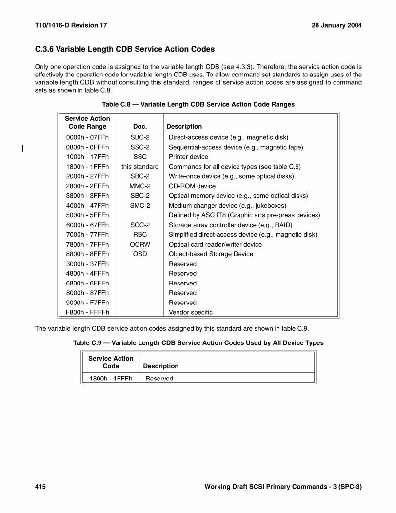
T10/1416-D Revision 17 28 January 2004
C.3.6 Variable Length CDB Service Action Codes
Only one operation code is assigned to the variable length CDB (see 4.3.3). Therefore, the service action code iseffectively the operation code for variable length CDB uses. To allow command set standards to assign uses of thevariable length CDB without consulting this standard, ranges of service action codes are assigned to commandsets as shown in table C.8.
The variable length CDB service action codes assigned by this standard are shown in table C.9.
Table C.8 — Variable Length CDB Service Action Code Ranges
Service Action Code Range Doc. Description
0000h - 07FFh SBC-2 Direct-access device (e.g., magnetic disk)
0800h - 0FFFh SSC-2 Sequential-access device (e.g., magnetic tape)
1000h - 17FFh SSC Printer device
1800h - 1FFFh this standard Commands for all device types (see table C.9)
2000h - 27FFh SBC-2 Write-once device (e.g., some optical disks)
2800h - 2FFFh MMC-2 CD-ROM device
3800h - 3FFFh SBC-2 Optical memory device (e.g., some optical disks)
4000h - 47FFh SMC-2 Medium changer device (e.g., jukeboxes)
5000h - 5FFFh Defined by ASC IT8 (Graphic arts pre-press devices)
6000h - 67FFh SCC-2 Storage array controller device (e.g., RAID)
7000h - 77FFh RBC Simplified direct-access device (e.g., magnetic disk)
7800h - 7FFFh OCRW Optical card reader/writer device
8800h - 8FFFh OSD Object-based Storage Device
3000h - 37FFh Reserved
4800h - 4FFFh Reserved
6800h - 6FFFh Reserved
8000h - 87FFh Reserved
9000h - F7FFh Reserved
F800h - FFFFh Vendor specific
Table C.9 — Variable Length CDB Service Action Codes Used by All Device Types
Service Action Code Description
1800h - 1FFFh Reserved
415 Working Draft SCSI Primary Commands - 3 (SPC-3)

28 January 2004 T10/1416-D Revision 17
C.4 Log Page Codes
Table C.10 is a numerical order listing of the log page codes.
Table C.10 — Log Page Codes
D - DIRECT ACCESS BLOCK DEVICE (SBC-2) Device Column key. T - SEQUENTIAL ACCESS DEVICE (SSC-2) blank = code not used. L - PRINTER DEVICE (SSC) not blank = code used. P - PROCESSOR DEVICE (SPC-2). . W- WRITE ONCE BLOCK DEVICE (SBC). . R - CD/DVD DEVICE (MMC-2). . O - OPTICAL MEMORY BLOCK DEVICE (SBC). . . M- MEDIA CHANGER DEVICE (SMC-2). . . A - STORAGE ARRAY DEVICE (SCC-2). . . E - ENCLOSURE SERVICES DEVICE (SES). . . . B - SIMPLIFIED DIRECT-ACCESS DEVICE (RBC). . . . K - OPTICAL CARD READER/WRITER DEVICE (OCRW). . . . V - AUTOMATION/DRIVE INTERFACE (ADC)
Log Page Code
. . . . . F - OBJECT-BASED STORAGE (OSD)
. . . . .D T L P W R O M A E B K Log Page Name
00h D T L P W R O M A E K V F Supported Log Pages01h D T L P W R O A K F Buffer Over-Run/Under-Run02h D T W R O K Write Error Counter03h D T W R O K Read Error Counter04h T Read Reverse Error Counter05h D T W R O K Verify Error Counter06h D T L P W R O M A E K F Non-Medium Error07h D T L P W R O M A E K F Last n Error Events08h D T W O Format Status09h O Reserved to the MS59 Std. (contact AIIM C21 comm.)0Ah O Reserved to the MS59 Std. (contact AIIM C21 comm.)0Bh D T L P W R O M A E F Last n Deferred Error Events0Ch T Sequential-Access Device0Dh D T L P W R O M A E Temperature0Eh D T L P W R O M A E Start-Stop Cycle counter0Fh D T L P W R O M A E Application Client10h D T L P W R O M A E Self-Test Results11h V DTD Status12h V TapeAlert Response13h V Requested Recovery14h V Device Statistics18h D T L P W R O M A E K Protocol Specific Port2Eh T M TapeAlert2Fh D T L P W R O M A E K Informational Exceptions
30h - 3Fh Vendor specific (does not require page format)
ALL CODES NOT SHOWN ARE RESERVED.
Working Draft SCSI Primary Commands - 3 (SPC-3) 416

T10/1416-D Revision 17 28 January 2004
C.5 Mode Page Codes
Table C.11 is a numerical order listing of the mode page codes.
Table C.11 — Mode Page Codes (part 1 of 2)
D - DIRECT ACCESS BLOCK DEVICE (SBC-2) Device Column key. T - SEQUENTIAL ACCESS DEVICE (SSC-2) blank = code not used. L - PRINTER DEVICE (SSC) not blank = code used. P - PROCESSOR DEVICE (SPC-2). . W- WRITE ONCE BLOCK DEVICE (SBC). . R - C/DVD DEVICE (MMC-2). . O- OPTICAL MEMORY BLOCK DEVICE (SBC). . . M- MEDIA CHANGER DEVICE (SMC-2). . . A - STORAGE ARRAY DEVICE (SCC-2). . . E - ENCLOSURE SERVICES DEVICE (SES). . . . B - SIMPLIFIED DIRECT-ACCESS DEVICE (RBC). . . . K - OPTICAL CARD READER/WRITER DEVICE (OCRW). . . . V - AUTOMATION/DRIVE INTERFACE (ADC)
Mode Page Code
Mode Subpage
Code
. . . . . F - OBJECT-BASED STORAGE (OSD)
. . . . .D T L P W R O M A E B K V F Mode Page Name
01h 00h D T W R O K Read-Write Error Recovery02h 00h D T L W R O M A E K V F Disconnect-Reconnect03h 00h D Format Device03h 00h L Parallel Printer Interface03h 00h R MRW CD-RW04h 00h D Rigid Disk Geometry04h 00h L Serial Printer Interface05h 00h D Flexible Disk05h 00h L Printer Options05h 00h R Write Parameters06h 00h W O Optical Memory06h 00h B RBC Device Parameters07h 00h D W O K Verify Error Recovery08h 00h D W R O K Caching09h 00h D T L W R O A E K obsolete0Ah 00h D T L W R O M A E K V F Control0Ah 01h D T L W R O M A E K V F Control Extension0Bh 00h D W O K Medium Types Supported0Ch 00h D Notch and Partition0Dh 00h D obsolete0Dh 00h R CD Device Parameters0Eh 00h R CD Audio Control0Eh 00h V ADC Device Configuration0Fh 00h T Data Compression10h 00h D XOR Control10h 00h T Device Configuration11h 00h T Medium Partition (1)12h13h14h 00h D T P W R O M A E B K V F Enclosure Services Management15h Extended16h Extended Device-Type Specific17h Reserved
a MMC-2 calls this page “Fault/Failure Reporting Page”, however, the page format is a proper subset of the format described in 7.4.11 of this standard.
417 Working Draft SCSI Primary Commands - 3 (SPC-3)
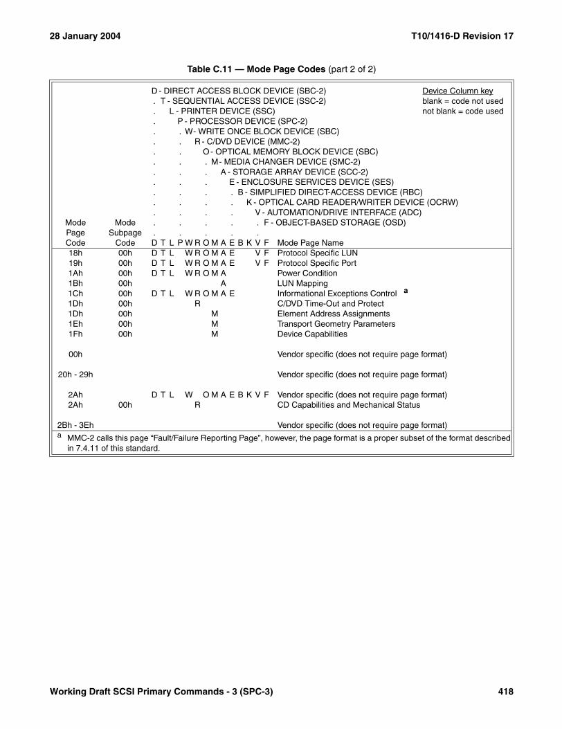
28 January 2004 T10/1416-D Revision 17
18h 00h D T L W R O M A E V F Protocol Specific LUN19h 00h D T L W R O M A E V F Protocol Specific Port1Ah 00h D T L W R O M A Power Condition1Bh 00h A LUN Mapping1Ch 00h D T L W R O M A E Informational Exceptions Control a
1Dh 00h R C/DVD Time-Out and Protect1Dh 00h M Element Address Assignments1Eh 00h M Transport Geometry Parameters1Fh 00h M Device Capabilities
00h Vendor specific (does not require page format)
20h - 29h Vendor specific (does not require page format)
2Ah D T L W O M A E B K V F Vendor specific (does not require page format)2Ah 00h R CD Capabilities and Mechanical Status
2Bh - 3Eh Vendor specific (does not require page format)
Table C.11 — Mode Page Codes (part 2 of 2)
D - DIRECT ACCESS BLOCK DEVICE (SBC-2) Device Column key. T - SEQUENTIAL ACCESS DEVICE (SSC-2) blank = code not used. L - PRINTER DEVICE (SSC) not blank = code used. P - PROCESSOR DEVICE (SPC-2). . W- WRITE ONCE BLOCK DEVICE (SBC). . R - C/DVD DEVICE (MMC-2). . O- OPTICAL MEMORY BLOCK DEVICE (SBC). . . M- MEDIA CHANGER DEVICE (SMC-2). . . A - STORAGE ARRAY DEVICE (SCC-2). . . E - ENCLOSURE SERVICES DEVICE (SES). . . . B - SIMPLIFIED DIRECT-ACCESS DEVICE (RBC). . . . K - OPTICAL CARD READER/WRITER DEVICE (OCRW). . . . V - AUTOMATION/DRIVE INTERFACE (ADC)
Mode Page Code
Mode Subpage
Code
. . . . . F - OBJECT-BASED STORAGE (OSD)
. . . . .D T L P W R O M A E B K V F Mode Page Name
a MMC-2 calls this page “Fault/Failure Reporting Page”, however, the page format is a proper subset of the format described in 7.4.11 of this standard.
Working Draft SCSI Primary Commands - 3 (SPC-3) 418
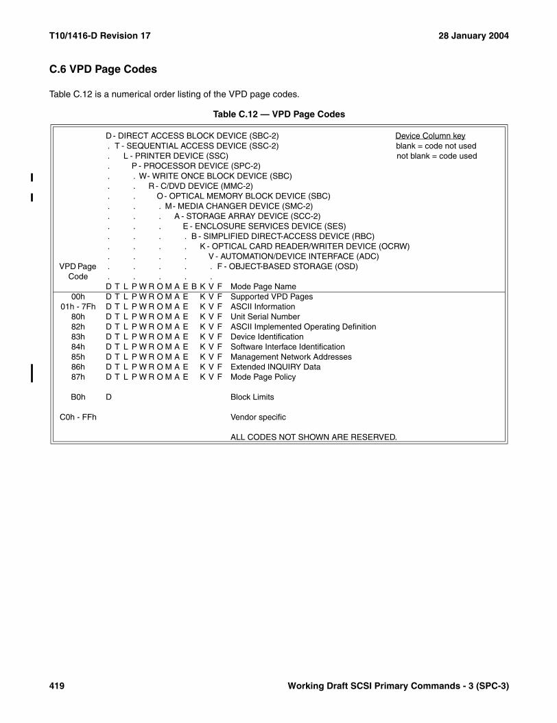
T10/1416-D Revision 17 28 January 2004
C.6 VPD Page Codes
Table C.12 is a numerical order listing of the VPD page codes.
Table C.12 — VPD Page Codes
D - DIRECT ACCESS BLOCK DEVICE (SBC-2) Device Column key. T - SEQUENTIAL ACCESS DEVICE (SSC-2) blank = code not used. L - PRINTER DEVICE (SSC) not blank = code used. P - PROCESSOR DEVICE (SPC-2). . W- WRITE ONCE BLOCK DEVICE (SBC). . R - C/DVD DEVICE (MMC-2). . O- OPTICAL MEMORY BLOCK DEVICE (SBC). . . M- MEDIA CHANGER DEVICE (SMC-2). . . A - STORAGE ARRAY DEVICE (SCC-2). . . E - ENCLOSURE SERVICES DEVICE (SES). . . . B - SIMPLIFIED DIRECT-ACCESS DEVICE (RBC). . . . K - OPTICAL CARD READER/WRITER DEVICE (OCRW). . . . V - AUTOMATION/DEVICE INTERFACE (ADC)
VPD Page Code
. . . . . F - OBJECT-BASED STORAGE (OSD)
. . . . .D T L P W R O M A E B K V F Mode Page Name
00h D T L P W R O M A E K V F Supported VPD Pages01h - 7Fh D T L P W R O M A E K V F ASCII Information
80h D T L P W R O M A E K V F Unit Serial Number82h D T L P W R O M A E K V F ASCII Implemented Operating Definition83h D T L P W R O M A E K V F Device Identification84h D T L P W R O M A E K V F Software Interface Identification85h D T L P W R O M A E K V F Management Network Addresses86h D T L P W R O M A E K V F Extended INQUIRY Data87h D T L P W R O M A E K V F Mode Page Policy
B0h D Block Limits
C0h - FFh Vendor specific
ALL CODES NOT SHOWN ARE RESERVED.
419 Working Draft SCSI Primary Commands - 3 (SPC-3)

28 January 2004 T10/1416-D Revision 17
C.7 Version Descriptor Values
Table C.13 is a numerical order listing of the version descriptor values used in the standard INQUIRY data. Eachversion descriptor value is computed from a coded value identifying the standard and a coded value representingthe revision of the standard. The formula is ((standard*32)+revison). Table C.13 shows all three code values andthe associated standard name. The version descriptor code is shown in both decimal and hexadecimal.
Table C.13 — Version descriptor assignments (part 1 of 8)
Standard Code
Revision Code
Version Descriptor Code
(decimal | hex) Standard
0 0 0 | 0000h Version Descriptor Not Supported or No Standard Identified
1 0 32 | 0020h SAM (no version claimed)
1 27 59 | 003Bh SAM T10/0994-D revision 18
1 28 60 | 003Ch SAM ANSI X3.270:1996
2 0 64 | 0040h SAM-2 (no version claimed)
2 20 84 | 0054h SAM-2 T10/1157-D revision 23
2 21 85 | 0055h SAM-2 T10/1157-D revision 24
2 28 92 | 005Ch SAM-2 ANSI INCITS.366:2003
3 0 96 | 0060h SAM-3 (no version claimed)
3 2 98 | 0062h SAM-3 T10/1561-D revision 7
9 0 288 | 0120h SPC (no version claimed)
9 27 315 | 013Bh SPC T10/0995-D revision 11a
9 28 316 | 013Ch SPC ANSI X3.301:1997
10 0 320 | 0140h MMC (no version claimed)
10 27 347 | 015Bh MMC T10/1048-D revision 10a
10 28 348 | 015Ch MMC ANSI X3.304:1997
11 0 352 | 0160h SCC (no version claimed)
11 27 379 | 017Bh SCC T10/1047-D revision 06c
11 28 380 | 017Ch SCC ANSI X3.276:1997
12 0 384 | 0180h SBC (no version claimed)
12 27 411 | 019Bh SBC T10/0996-D revision 08c
12 28 412 | 019Ch SBC ANSI NCITS.306:1998
13 0 416 | 01A0h SMC (no version claimed)
13 27 443 | 01BBh SMC T10/0999-D revision 10a
13 28 444 | 01BCh SMC ANSI NCITS.314:1998
Working Draft SCSI Primary Commands - 3 (SPC-3) 420
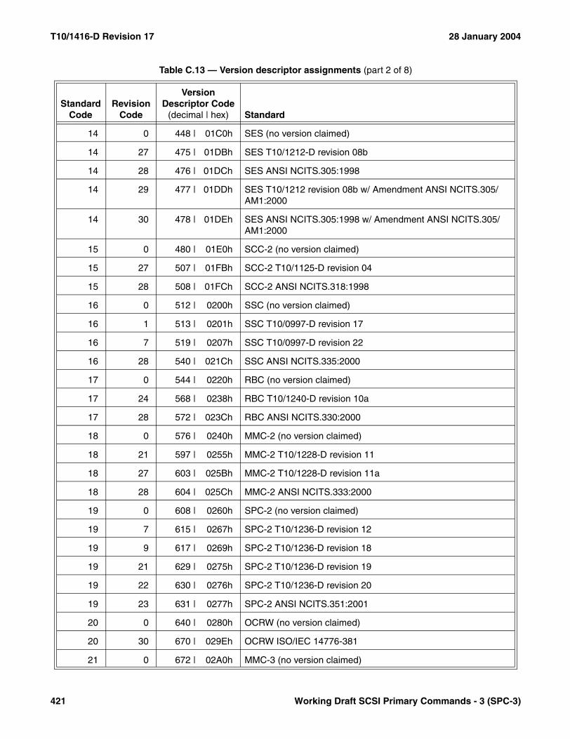
T10/1416-D Revision 17 28 January 2004
14 0 448 | 01C0h SES (no version claimed)
14 27 475 | 01DBh SES T10/1212-D revision 08b
14 28 476 | 01DCh SES ANSI NCITS.305:1998
14 29 477 | 01DDh SES T10/1212 revision 08b w/ Amendment ANSI NCITS.305/AM1:2000
14 30 478 | 01DEh SES ANSI NCITS.305:1998 w/ Amendment ANSI NCITS.305/AM1:2000
15 0 480 | 01E0h SCC-2 (no version claimed)
15 27 507 | 01FBh SCC-2 T10/1125-D revision 04
15 28 508 | 01FCh SCC-2 ANSI NCITS.318:1998
16 0 512 | 0200h SSC (no version claimed)
16 1 513 | 0201h SSC T10/0997-D revision 17
16 7 519 | 0207h SSC T10/0997-D revision 22
16 28 540 | 021Ch SSC ANSI NCITS.335:2000
17 0 544 | 0220h RBC (no version claimed)
17 24 568 | 0238h RBC T10/1240-D revision 10a
17 28 572 | 023Ch RBC ANSI NCITS.330:2000
18 0 576 | 0240h MMC-2 (no version claimed)
18 21 597 | 0255h MMC-2 T10/1228-D revision 11
18 27 603 | 025Bh MMC-2 T10/1228-D revision 11a
18 28 604 | 025Ch MMC-2 ANSI NCITS.333:2000
19 0 608 | 0260h SPC-2 (no version claimed)
19 7 615 | 0267h SPC-2 T10/1236-D revision 12
19 9 617 | 0269h SPC-2 T10/1236-D revision 18
19 21 629 | 0275h SPC-2 T10/1236-D revision 19
19 22 630 | 0276h SPC-2 T10/1236-D revision 20
19 23 631 | 0277h SPC-2 ANSI NCITS.351:2001
20 0 640 | 0280h OCRW (no version claimed)
20 30 670 | 029Eh OCRW ISO/IEC 14776-381
21 0 672 | 02A0h MMC-3 (no version claimed)
Table C.13 — Version descriptor assignments (part 2 of 8)
Standard Code
Revision Code
Version Descriptor Code
(decimal | hex) Standard
421 Working Draft SCSI Primary Commands - 3 (SPC-3)

28 January 2004 T10/1416-D Revision 17
21 21 693 | 02B5h MMC-3 T10/1363-D revision 9
21 22 694 | 02B6h MMC-3 T10/1363-D revision 10g
21 24 696 | 02B8h MMC-3 ANSI INCITS.360:2002
23 0 736 | 02E0h SMC-2 (no version claimed)
23 21 757 | 02F5h SMC-2 T10/1383-D revision 5
23 28 764 | 02FCh SMC-2 T10/1383-D revision 6
23 29 765 | 02FDh SMC-2 T10/1383-D revision 7
24 0 768 | 0300h SPC-3 (no version claimed)
24 1 769 | 0301h SPC-3 T10/1416-D revision 7
25 0 800 | 0320h SBC-2 (no version claimed)
25 2 802 | 0322h SBC-2 T10/1417-D revision 5a
26 0 832 | 0340h OSD (no version claimed)
26 1 833 | 0341h OSD T10/1355-D revision 0
26 2 834 | 0342h OSD T10/1355-D revision 7a
26 3 835 | 0343h OSD T10/1355-D revision 8
26 4 836 | 0344h OSD T10/1355-D revision 9
27 0 864 | 0360h SSC-2 (no version claimed)
27 20 884 | 0374h SSC-2 T10/1434-D revision 7
27 21 885 | 0375h SSC-2 T10/1434-D revision 9
27 29 893 | 037Dh SSC-2 ANSI INCITS.380:2003
28 0 896 | 0380h MSC (no version claimed)
29 0 928 | 03A0h MMC-4 (no version claimed)
30 0 960 | 03C0h ADC (no version claimed)
30 21 981 | 03D5h ADC T10/1558-D revision 6
31 0 992 | 03E0h SES-2 (no version claimed)
32 0 1024 | 0400h SSC-3 (no version claimed)
33 0 1056 | 0420h MMC-5 (no version claimed)
65 0 2080 | 0820h SSA-TL2 (no version claimed)
65 27 2107 | 083Bh SSA-TL2 T10.1/1147-D revision 05b
Table C.13 — Version descriptor assignments (part 3 of 8)
Standard Code
Revision Code
Version Descriptor Code
(decimal | hex) Standard
Working Draft SCSI Primary Commands - 3 (SPC-3) 422

T10/1416-D Revision 17 28 January 2004
65 28 2108 | 083Ch SSA-TL2 ANSI NCITS.308:1998
66 0 2112 | 0840h SSA-TL1 (no version claimed)
66 27 2139 | 085Bh SSA-TL1 T10.1/0989-D revision 10b
66 28 2140 | 085Ch SSA-TL1 ANSI X3.295:1996
67 0 2144 | 0860h SSA-S3P (no version claimed)
67 27 2171 | 087Bh SSA-S3P T10.1/1051-D revision 05b
67 28 2172 | 087Ch SSA-S3P ANSI NCITS.309:1998
68 0 2176 | 0880h SSA-S2P (no version claimed)
68 27 2203 | 089Bh SSA-S2P T10.1/1121-D revision 07b
68 28 2204 | 089Ch SSA-S2P ANSI X3.294:1996
69 0 2208 | 08A0h SIP (no version claimed)
69 27 2235 | 08BBh SIP T10/0856-D revision 10
69 28 2236 | 08BCh SIP ANSI X3.292:1997
70 0 2240 | 08C0h FCP (no version claimed)
70 27 2267 | 08DBh FCP T10/0993-D revision 12
70 28 2268 | 08DCh FCP ANSI X3.269:1996
71 0 2272 | 08E0h SBP-2 (no version claimed)
71 27 2299 | 08FBh SBP-2 T10/1155-D revision 04
71 28 2300 | 08FCh SBP-2 ANSI NCITS.325:1999
72 0 2304 | 0900h FCP-2 (no version claimed)
72 1 2305 | 0901h FCP-2 T10/1144-D revision 4
72 21 2325 | 0915h FCP-2 T10/1144-D revision 7
72 22 2326 | 0916h FCP-2 T10/1144-D revision 7a
72 23 2327 | 0917h FCP-2 ANSI INCITS.350:2003
72 24 2328 | 0918h FCP-2 T10/1144-D revision 8
73 0 2336 | 0920h SST (no version claimed)
73 21 2357 | 0935h SST T10/1380-D revision 8b
74 0 2368 | 0940h SRP (no version claimed)
74 20 2388 | 0954h SRP T10/1415-D revision 10
Table C.13 — Version descriptor assignments (part 4 of 8)
Standard Code
Revision Code
Version Descriptor Code
(decimal | hex) Standard
423 Working Draft SCSI Primary Commands - 3 (SPC-3)

28 January 2004 T10/1416-D Revision 17
74 21 2389 | 0955h SRP T10/1415-D revision 16a
74 28 2396 | 095Ch SRP ANSI INCITS.365:2002
75 0 2400 | 0960h iSCSI (no version claimed)
76 0 2432 | 0980h SBP-3 (no version claimed)
76 2 2434 | 0982h SBP-3 T10/1467-D revision 1f
76 20 2452 | 0994h SBP-3 T10/1467-D revision 3
76 26 2458 | 099Ah SBP-3 T10/1467-D revision 4
76 27 2459 | 099Bh SBP-3 T10/1467-D revision 5
77 0 2464 | 09A0h SRP-2 (no version claimed)
78 0 2496 | 09C0h ADP (no version claimed)
79 0 2528 | 09E0h ADT (no version claimed)
80 0 2560 | 0A00h FCP-3 (no version claimed)
85 0 2720 | 0AA0h SPI (no version claimed)
85 25 2745 | 0AB9h SPI T10/0855-D revision 15a
85 26 2746 | 0ABAh SPI ANSI X3.253:1995
85 27 2747 | 0ABBh SPI T10/0855-D revision 15a with SPI Amnd revision 3a
85 28 2748 | 0ABCh SPI ANSI X3.253:1995 with SPI Amnd ANSI X3.253/AM1:1998
86 0 2752 | 0AC0h Fast-20 (no version claimed)
86 27 2779 | 0ADBh Fast-20 T10/1071 revision 06
86 28 2780 | 0ADCh Fast-20 ANSI X3.277:1996
87 0 2784 | 0AE0h SPI-2 (no version claimed)
87 27 2811 | 0AFBh SPI-2 T10/1142-D revision 20b
87 28 2812 | 0AFCh SPI-2 ANSI X3.302:1999
88 0 2816 | 0B00h SPI-3 (no version claimed)
88 24 2840 | 0B18h SPI-3 T10/1302-D revision 10
88 25 2841 | 0B19h SPI-3 T10/1302-D revision 13a
88 26 2842 | 0B1Ah SPI-3 T10/1302-D revision 14
88 28 2844 | 0B1Ch SPI-3 ANSI NCITS.336:2000
89 0 2848 | 0B20h EPI (no version claimed)
Table C.13 — Version descriptor assignments (part 5 of 8)
Standard Code
Revision Code
Version Descriptor Code
(decimal | hex) Standard
Working Draft SCSI Primary Commands - 3 (SPC-3) 424

T10/1416-D Revision 17 28 January 2004
89 27 2875 | 0B3Bh EPI T10/1134 revision 16
89 28 2876 | 0B3Ch EPI ANSI NCITS TR-23:1999
90 0 2880 | 0B40h SPI-4 (no version claimed)
90 20 2900 | 0B54h SPI-4 T10/1365-D revision 7
90 21 2901 | 0B55h SPI-4 T10/1365-D revision 9
90 22 2902 | 0B56h SPI-4 ANSI INCITS.362:2002
90 25 2905 | 0B59h SPI-4 T10/1365-D revision 10
91 0 2912 | 0B60h SPI-5 (no version claimed)
91 25 2937 | 0B79h SPI-5 T10/1525-D revision 3
91 26 2938 | 0B7Ah SPI-5 T10/1525-D revision 5
91 27 2939 | 0B7Bh SPI-5 T10/1525-D revision 6
91 28 2940 | 0B7Ch SPI-5 ANSI INCITS.367:2003
95 0 3040 | 0BE0h SAS (no version claimed)
95 1 3041 | 0BE1h SAS T10/1562-D revision 01
95 21 3061 | 0BF5h SAS T10/1562-D revision 03
95 26 3066 | 0BFAh SAS T10/1562-D revision 04
95 27 3067 | 0BFBh SAS T10/1562-D revision 04
95 28 3068 | 0BFCh SAS T10/1562-D revision 05
95 29 3069 | 0BFDh SAS ANSI INCITS.376:2003
96 0 3072 | 0C00h SAS-1.1 (no version claimed)
105 0 3360 | 0D20h FC-PH (no version claimed)
105 27 3387 | 0D3Bh FC-PH ANSI X3.230:1994
105 28 3388 | 0D3Ch FC-PH ANSI X3.230:1994 with Amnd 1 ANSI X3.230/AM1:1996
106 0 3392 | 0D40h FC-AL (no version claimed)
106 28 3420 | 0D5Ch FC-AL ANSI X3.272:1996
107 0 3424 | 0D60h FC-AL-2 (no version claimed)
107 1 3425 | 0D61h FC-AL-2 T11/1133-D revision 7.0
107 28 3452 | 0D7Ch FC-AL-2 ANSI NCITS.332:1999
107 29 3453 | 0D7Dh FC-AL-2 ANSI NCITS.332:1999 with Amnd 1 AM1:2002
Table C.13 — Version descriptor assignments (part 6 of 8)
Standard Code
Revision Code
Version Descriptor Code
(decimal | hex) Standard
425 Working Draft SCSI Primary Commands - 3 (SPC-3)
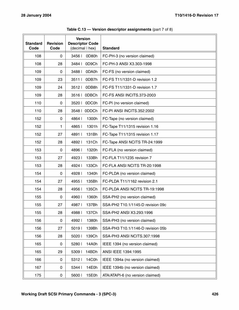
28 January 2004 T10/1416-D Revision 17
108 0 3456 | 0D80h FC-PH-3 (no version claimed)
108 28 3484 | 0D9Ch FC-PH-3 ANSI X3.303-1998
109 0 3488 | 0DA0h FC-FS (no version claimed)
109 23 3511 | 0DB7h FC-FS T11/1331-D revision 1.2
109 24 3512 | 0DB8h FC-FS T11/1331-D revision 1.7
109 28 3516 | 0DBCh FC-FS ANSI INCITS.373-2003
110 0 3520 | 0DC0h FC-PI (no version claimed)
110 28 3548 | 0DDCh FC-PI ANSI INCITS.352:2002
152 0 4864 | 1300h FC-Tape (no version claimed)
152 1 4865 | 1301h FC-Tape T11/1315 revision 1.16
152 27 4891 | 131Bh FC-Tape T11/1315 revision 1.17
152 28 4892 | 131Ch FC-Tape ANSI NCITS TR-24:1999
153 0 4896 | 1320h FC-FLA (no version claimed)
153 27 4923 | 133Bh FC-FLA T11/1235 revision 7
153 28 4924 | 133Ch FC-FLA ANSI NCITS TR-20:1998
154 0 4928 | 1340h FC-PLDA (no version claimed)
154 27 4955 | 135Bh FC-PLDA T11/1162 revision 2.1
154 28 4956 | 135Ch FC-PLDA ANSI NCITS TR-19:1998
155 0 4960 | 1360h SSA-PH2 (no version claimed)
155 27 4987 | 137Bh SSA-PH2 T10.1/1145-D revision 09c
155 28 4988 | 137Ch SSA-PH2 ANSI X3.293:1996
156 0 4992 | 1380h SSA-PH3 (no version claimed)
156 27 5019 | 139Bh SSA-PH3 T10.1/1146-D revision 05b
156 28 5020 | 139Ch SSA-PH3 ANSI NCITS.307:1998
165 0 5280 | 14A0h IEEE 1394 (no version claimed)
165 29 5309 | 14BDh ANSI IEEE 1394:1995
166 0 5312 | 14C0h IEEE 1394a (no version claimed)
167 0 5344 | 14E0h IEEE 1394b (no version claimed)
175 0 5600 | 15E0h ATA/ATAPI-6 (no version claimed)
Table C.13 — Version descriptor assignments (part 7 of 8)
Standard Code
Revision Code
Version Descriptor Code
(decimal | hex) Standard
Working Draft SCSI Primary Commands - 3 (SPC-3) 426

T10/1416-D Revision 17 28 January 2004
Table C.14 shows the guidelines used by T10 when selecting a coded value for a standard.
175 29 5629 | 15FDh ATA/ATAPI-6 ANSI INCITS.361:2002
176 0 5632 | 1600h ATA/ATAPI-7 (no version claimed)
176 2 5634 | 1602h ATA/ATAPI-7 T13/1532-D revision 3
185 8 5928 | 1728h Universal Serial Bus Specification, Revision 1.1
185 9 5929 | 1729h Universal Serial Bus Specification, Revision 2.0
185 16 5936 | 1730h USB Mass Storage Class Bulk-Only Transport, Revision 1.0
Table C.14 — Standard code value guidelines (part 1 of 4)
Standard Code Standard or standards family
0 Version Descriptor Not Supported
1 - 8 Architecture Model
1 SAM
2 SAM-2
3 SAM-3
9 - 64 Command Set
9 SPC
10 MMC
11 SCC
12 SBC
13 SMC
14 SES
15 SCC-2
16 SSC
17 RBC
18 MMC-2
19 SPC-2
20 OCRW
21 MMC-3
22 obsolete
Table C.13 — Version descriptor assignments (part 8 of 8)
Standard Code
Revision Code
Version Descriptor Code
(decimal | hex) Standard
427 Working Draft SCSI Primary Commands - 3 (SPC-3)

28 January 2004 T10/1416-D Revision 17
23 SMC-2
24 SPC-3
25 SBC-2
26 OSD
27 SSC-2
28 MSC
29 MMC-4
30 ADC
31 SES-2
32 SSC-3
33 MMC-5
65 - 84 Physical Mapping Protocol
65 SSA-TL2
66 SSA-TL1
67 SSA-S3P
68 SSA-S2P
69 SIP
70 FCP
71 SBP-2
72 FCP-2
73 SST
74 SRP
75 iSCSI
76 SBP-3
77 SRP-2
78 ADP
79 ADT
80 FCP-3
85 - 94 Parallel SCSI Physical
85 SPI and SPI Amendment
86 Fast-20
Table C.14 — Standard code value guidelines (part 2 of 4)
Standard Code Standard or standards family
Working Draft SCSI Primary Commands - 3 (SPC-3) 428

T10/1416-D Revision 17 28 January 2004
87 SPI-2
88 SPI-3
89 EPI
90 SPI-4
91 SPI-5
95 - 104 Serial Attached SCSI
95 SAS
96 SAS-2
105 - 154 Fibre Channel
105 FC-PH and FC-PH Amendment
106 FC-AL
107 FC-AL-2
108 FC-PH-3
109 FC-FS
110 FC-PI
152 FC-Tape
153 FC-FLA
154 FC-PLDA
155 - 164 SSA
155 SSA-PH2
156 SSA-PH3
165 - 174 IEEE 1394
165 IEEE 1394:1995
166 IEEE 1394a
167 IEEE 1394b
175-185 ATAPI & USB
175 ATAPI-6
176 ATAPI-7
Table C.14 — Standard code value guidelines (part 3 of 4)
Standard Code Standard or standards family
429 Working Draft SCSI Primary Commands - 3 (SPC-3)
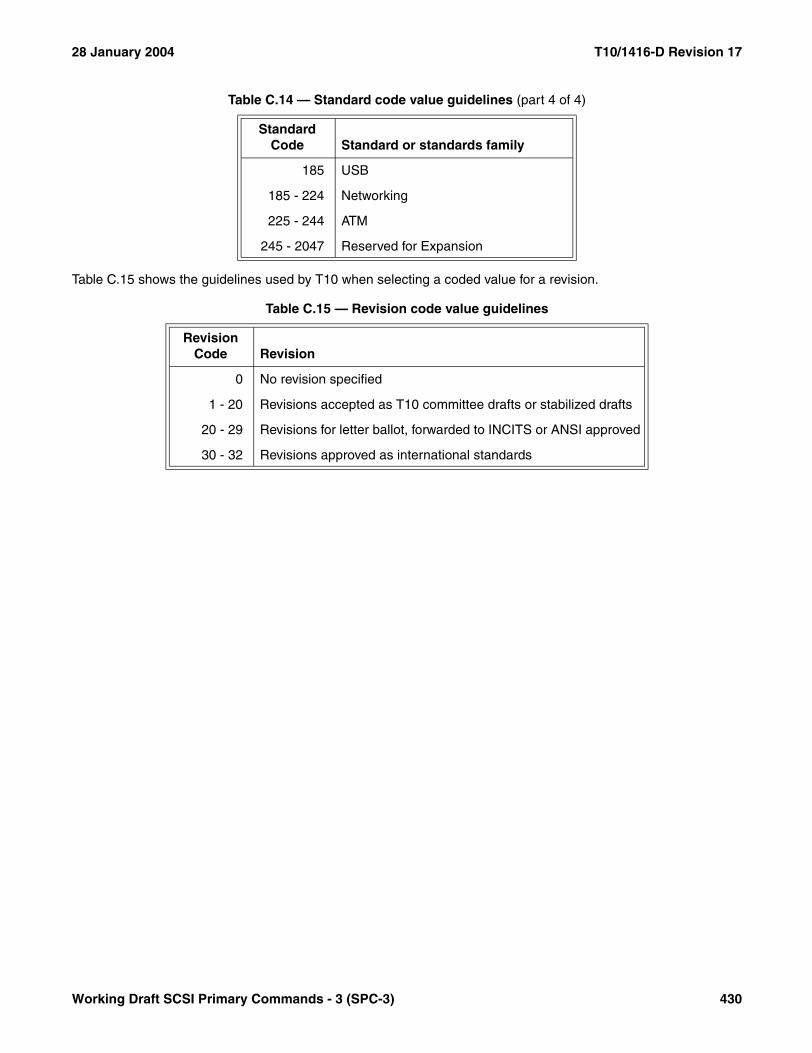
28 January 2004 T10/1416-D Revision 17
Table C.15 shows the guidelines used by T10 when selecting a coded value for a revision.
185 USB
185 - 224 Networking
225 - 244 ATM
245 - 2047 Reserved for Expansion
Table C.15 — Revision code value guidelines
Revision Code Revision
0 No revision specified
1 - 20 Revisions accepted as T10 committee drafts or stabilized drafts
20 - 29 Revisions for letter ballot, forwarded to INCITS or ANSI approved
30 - 32 Revisions approved as international standards
Table C.14 — Standard code value guidelines (part 4 of 4)
Standard Code Standard or standards family
Working Draft SCSI Primary Commands - 3 (SPC-3) 430

T10/1416-D Revision 17 28 January 2004
C.8 T10 IEEE binary identifiers
The IEEE binary identifiers assigned to T10 standards are shown in table C.16.
Table C.16 — IEEE binary identifiers assigned by T10
IEEE Binary Identifier T10 Standard
0060 9E01 03E0h SBP (obsolete)
0060 9E01 0483h SBP-2
0060 9E01 04D8h SPC-2
0060 9E01 05BBh SBP-3
0060 9E01 0800h SRP revision 10
0060 9E01 0801h ANSI SRP
431 Working Draft SCSI Primary Commands - 3 (SPC-3)

28 January 2004 T10/1416-D Revision 17
Annex D(informative)
Vendor identification
This annex contains the list of SCSI vendor identifications (see table D.1) as of the date of this document. Thepurpose of this list is to help avoid redundant usage of vendor identifications. Technical Committee T10 ofAccredited Standards Committee INCITS maintains an informal list of vendor identifications currently in use. TheT10 web site, www.t10.org, provides a convenient means to request an identification code. If problems are encoun-tered using the T10 web site, please contact the chairman of T10 prior to using a new vendor identification to avoidconflicts.
The information in this annex was complete and accurate at the time of publication. However, the information issubject to change. Technical Committee T10 of INCITS maintains an electronic copy of this information on its worldwide web site (http://www.t10.org/). In the event that the T10 world wide web site is no longer active, access maybe possible via the INCITS world wide web site (http://www.incits.org), the ANSI world wide web site (http://www.ansi.org), the IEC site (http://www.iec.ch/), the ISO site (http://www.iso.ch/), or the ISO/IEC JTC 1 web site(http://www.jtc1.org/).
Table D.1 — Vendor identification list (part 1 of 10)
ID Organization
0B4C MOOSIK Ltd.2AI 2AI (Automatisme et Avenir Informatique)3M 3M Company3PARdata 3PARdata, Inc.A-Max A-Max Technology Co., LtdAcer Acer, Inc.ACL Automated Cartridge Librarys, Inc.Acuid Acuid Corporation Ltd.AcuLab AcuLab, Inc. (Tulsa, OK)ADAPTEC AdaptecADIC Advanced Digital Information CorporationADSI Adaptive Data Systems, Inc. (a Western Digital subsidiary)ADTX ADTX Co., Ltd.ADVA ADVA Optical Networking AGAERONICS Aeronics, Inc.AGFA AGFAAIPTEK AIPTEK International Inc.AMCODYNE AmcodyneAmphenol AmphenolANAMATIC Anamartic Limited (England)Ancor Ancor Communications, Inc.ANCOT ANCOT Corp.ANDATACO Andataco (now nStor)andiamo Andiamo Systems, Inc.ANRITSU Anritsu CorporationAPPLE Apple Computer, Inc.ARCHIVE ArchiveARISTOS Aristos Logic Corp.
Working Draft SCSI Primary Commands - 3 (SPC-3) 432

T10/1416-D Revision 17 28 January 2004
ARK ARK Research CorporationARTECON Artecon Inc. (Obs. - now Dot Hill)ASACA ASACA Corp.ASC Advanced Storage Concepts, Inc.ASPEN Aspen PeripheralsAST AST ResearchASTK Alcatel STK A/SAT&T AT&TATARI Atari CorporationATG CYG ATG Cygnet Inc.ATL Quantum|ATL ProductsATTO ATTO Technology Inc.ATX AlphatronixAVC AVC Technology LtdAVR Advanced Vision ResearchBALLARD Ballard Synergy Corp.BAROMTEC Barom Technologies Co., Ltd.BDT Buero- und Datentechnik GmbH & Co.KGBENQ BENQ Corporation.BERGSWD Berg Software DesignBEZIER Bezier Systems, Inc.BHTi Breece Hill TechnologiesBIR Bio-Imaging Research, Inc.BiT BiT Microsystems (obsolete, new ID: BITMICRO)BITMICRO BiT Microsystems, Inc.BNCHMARK Benchmark Tape Systems CorporationBoxHill Box Hill Systems Corporation (Obs. - now Dot Hill)BREA BREA Technologies, Inc.BROCADE Brocade Communications Systems, IncorporatedBULL Bull Peripherals Corp.BUSLOGIC BusLogic Inc.CalComp CalComp, A Lockheed CompanyCALIPER Caliper (California Peripheral Corp.)CAMBEX Cambex CorporationCANDERA Candera Inc.CAPTION CAPTION BANKCAST Advanced Storage TechCDC Control Data or MPICDP Columbia Data ProductsCenData Central Data CorporationCereva Cereva Networks Inc.CERTANCE CertanceCHEROKEE Cherokee Data SystemsCHINON ChinonCIE&YED YE Data, C.Itoh Electric Corp.CIPHER Cipher Data ProductsCiprico Ciprico, Inc.
Table D.1 — Vendor identification list (part 2 of 10)
ID Organization
433 Working Draft SCSI Primary Commands - 3 (SPC-3)

28 January 2004 T10/1416-D Revision 17
CIRRUSL Cirrus Logic Inc.CISCO Cisco Systems, Inc.CLOVERLF Cloverleaf Communications, IncCMD CMD Technology Inc.CMTechno CMTechCNGR SFW Congruent Software, Inc.CNSi Chaparral Network Storage, Inc.CNT Computer Network TechnologyCOBY Coby Electronics Corporation, USACOGITO CogitoCOMPAQ Compaq Computer Corporation (now HP)COMPELNT Compellent Technologies, Inc.COMPORT Comport Corp.COMPSIG Computer Signal CorporationCOMPTEX Comptex Pty LimitedCONNER Conner PeripheralsCORE Core International, Inc.COWON COWON SYSTEMS, Inc.CPL Cross Products LtdCPU TECH CPU Technology, Inc.CREO Creo Products Inc.CROSFLD Crosfield Electronics (now FujiFilm Electonic Imaging Ltd)CROSSRDS Crossroads Systems, Inc.CSCOVRTS Cisco - VeritasCSM, INC Computer SM, Inc.Data Com Data Com Information Systems Pty. Ltd.DATABOOK Databook, Inc.DATACOPY Datacopy Corp.DataCore DataCore Software CorporationDATAPT Datapoint Corp.DDN DataDirect Networks, Inc.DEC Digital Equipment Corporation (now HP)DEI Digital Engineering, Inc.DELL Dell Computer CorporationDELPHI Delphi Data Div. of Sparks Industries, Inc.DENON Denon/Nippon ColumbiaDenOptix DenOptix, Inc.DEST DEST Corp.DGC Data General Corp.DIGIDATA Digi-Data CorporationDigiIntl Digi InternationalDigital Digital Equipment Corporation (now HP)DILOG Distributed Logic Corp.DISC Document Imaging Systems Corp.DLNET DrivelineDNS Data and Network SecurityDotHill Dot Hill Systems Corp.
Table D.1 — Vendor identification list (part 3 of 10)
ID Organization
Working Draft SCSI Primary Commands - 3 (SPC-3) 434

T10/1416-D Revision 17 28 January 2004
DPT Distributed Processing TechnologyDSI Data Spectrum, Inc.DSM Deterner Steuerungs- und Maschinenbau GmbH & Co.DTC QUME Data Technology QumeDXIMAGIN DX ImagingECCS ECCS, Inc.ECMA European Computer Manufacturers Associationelipsan Elipsan UK Ltd.Elms Elms Systems CorporationEMASS EMASS, Inc.EMC EMC Corp.EMTEC EMTEC MagneticsEMULEX EmulexENERGY-B Energybeam CorporationEPSON EpsonEQLOGIC EqualLogiceqlogic EqualLogicEris/RSI RSI Systems, Inc.EuroLogc Eurologic Systems Limitedevolve Evolution Technologies, IncEXABYTE Exabyte Corp.EXATEL Exatelecom Co., Ltd.EXAVIO Exavio, Inc.FALCON FalconStor, Inc.FFEILTD FujiFilm Electonic Imaging LtdFibxn Fiberxon, Inc.FID First International Digital, Inc.FILENET FileNet Corp.FRAMDRV FRAMEDRIVE Corp.FUJI Fuji Electric Co., Ltd. (Japan)FUJIFILM Fuji Photo Film, Co., Ltd.FUJITSU FujitsuFUNAI Funai Electric Co., Ltd.FUTURED Future Domain Corp.G&D Giesecke & Devrient GmbHGadzoox Gadzoox Networks, Inc.GDI Generic Distribution InternationalGen_Dyn General DynamicsGeneric Generic Technology Co., Ltd.GENSIG General Signal NetworksGIGATAPE GIGATAPE GmbHGIGATRND GigaTrend IncorporatedGlobal Global Memory Test ConsortiumGoidelic Goidelic Precision, Inc.GoldStar LG Electronics Inc.GOULD GouldHAGIWARA Hagiwara Sys-Com Co., Ltd.
Table D.1 — Vendor identification list (part 4 of 10)
ID Organization
435 Working Draft SCSI Primary Commands - 3 (SPC-3)
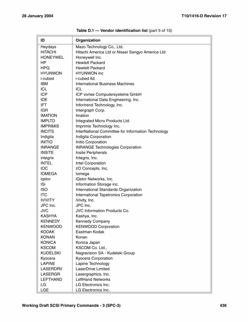
28 January 2004 T10/1416-D Revision 17
Heydays Mazo Technology Co., Ltd.HITACHI Hitachi America Ltd or Nissei Sangyo America LtdHONEYWEL Honeywell Inc.HP Hewlett PackardHPQ Hewlett PackardHYUNWON HYUNWON inci-cubed i-cubed ltd.IBM International Business MachinesICL ICLICP ICP vortex Computersysteme GmbHIDE International Data Engineering, Inc.IFT Infortrend Technology, Inc.IGR Intergraph Corp.IMATION ImationIMPLTD Integrated Micro Products Ltd.IMPRIMIS Imprimis Technology Inc.INCITS InterNational Committee for Information TechnologyIndigita Indigita CorporationINITIO Initio CorporationINRANGE INRANGE Technologies CorporationINSITE Insite Peripheralsintegrix Integrix, Inc.INTEL Intel CorporationIOC I/O Concepts, Inc.IOMEGA Iomegaiqstor iQstor Networks, Inc.ISi Information Storage inc.ISO International Standards OrganizationITC International Tapetronics CorporationIVIVITY iVivity, Inc.JPC Inc. JPC Inc.JVC JVC Information Products Co.KASHYA Kashya, Inc.KENNEDY Kennedy CompanyKENWOOD KENWOOD CorporationKODAK Eastman KodakKONAN KonanKONICA Konica JapanKSCOM KSCOM Co. Ltd.,KUDELSKI Nagravision SA - Kudelski GroupKyocera Kyocera CorporationLAPINE Lapine TechnologyLASERDRV LaserDrive LimitedLASERGR Lasergraphics, Inc.LEFTHAND LeftHand NetworksLG LG Electronics Inc.LGE LG Electronics Inc.
Table D.1 — Vendor identification list (part 5 of 10)
ID Organization
Working Draft SCSI Primary Commands - 3 (SPC-3) 436
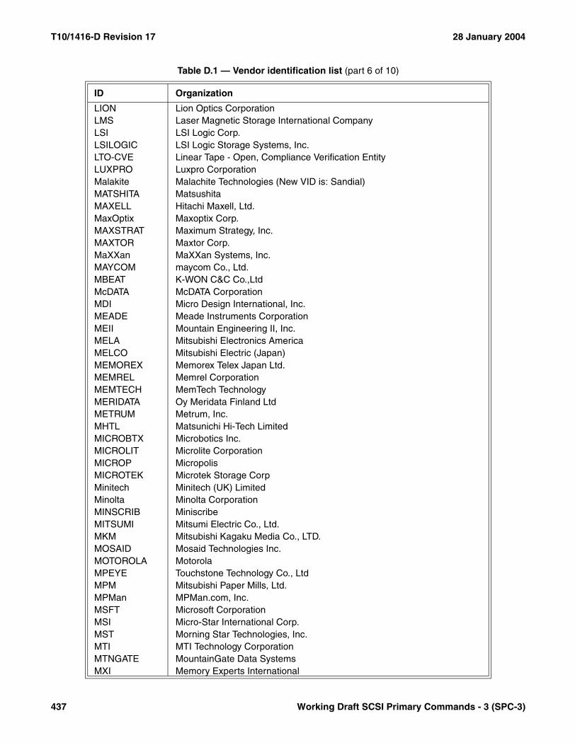
T10/1416-D Revision 17 28 January 2004
LION Lion Optics CorporationLMS Laser Magnetic Storage International CompanyLSI LSI Logic Corp.LSILOGIC LSI Logic Storage Systems, Inc.LTO-CVE Linear Tape - Open, Compliance Verification EntityLUXPRO Luxpro CorporationMalakite Malachite Technologies (New VID is: Sandial)MATSHITA MatsushitaMAXELL Hitachi Maxell, Ltd.MaxOptix Maxoptix Corp.MAXSTRAT Maximum Strategy, Inc.MAXTOR Maxtor Corp.MaXXan MaXXan Systems, Inc.MAYCOM maycom Co., Ltd.MBEAT K-WON C&C Co.,LtdMcDATA McDATA CorporationMDI Micro Design International, Inc.MEADE Meade Instruments CorporationMEII Mountain Engineering II, Inc.MELA Mitsubishi Electronics AmericaMELCO Mitsubishi Electric (Japan)MEMOREX Memorex Telex Japan Ltd.MEMREL Memrel CorporationMEMTECH MemTech TechnologyMERIDATA Oy Meridata Finland LtdMETRUM Metrum, Inc.MHTL Matsunichi Hi-Tech LimitedMICROBTX Microbotics Inc.MICROLIT Microlite CorporationMICROP MicropolisMICROTEK Microtek Storage CorpMinitech Minitech (UK) LimitedMinolta Minolta CorporationMINSCRIB MiniscribeMITSUMI Mitsumi Electric Co., Ltd.MKM Mitsubishi Kagaku Media Co., LTD.MOSAID Mosaid Technologies Inc.MOTOROLA MotorolaMPEYE Touchstone Technology Co., LtdMPM Mitsubishi Paper Mills, Ltd.MPMan MPMan.com, Inc.MSFT Microsoft CorporationMSI Micro-Star International Corp.MST Morning Star Technologies, Inc.MTI MTI Technology CorporationMTNGATE MountainGate Data SystemsMXI Memory Experts International
Table D.1 — Vendor identification list (part 6 of 10)
ID Organization
437 Working Draft SCSI Primary Commands - 3 (SPC-3)
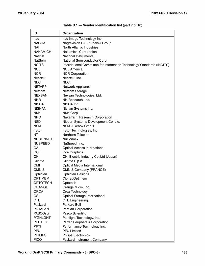
28 January 2004 T10/1416-D Revision 17
nac nac Image Technology Inc.NAGRA Nagravision SA - Kudelski GroupNAI North Atlantic IndustriesNAKAMICH Nakamichi CorporationNatInst National InstrumentsNatSemi National Semiconductor Corp.NCITS InterNational Committee for Information Technology Standards (INCITS)NCL NCL AmericaNCR NCR CorporationNeartek Neartek, Inc.NEC NECNETAPP Network ApplianceNetcom Netcom StorageNEXSAN Nexsan Technologies, Ltd.NHR NH Research, Inc.NISCA NISCA Inc.NISHAN Nishan Systems Inc.NKK NKK Corp.NRC Nakamichi Research CorporationNSD Nippon Systems Development Co.,Ltd.NSM NSM Jukebox GmbHnStor nStor Technologies, Inc.NT Northern TelecomNUCONNEX NuConnexNUSPEED NuSpeed, Inc.OAI Optical Access InternationalOCE Oce GraphicsOKI OKI Electric Industry Co.,Ltd (Japan)Olidata Olidata S.p.A.OMI Optical Media InternationalOMNIS OMNIS Company (FRANCE)Ophidian Ophidian DesignsOPTIMEM Cipher/OptimemOPTOTECH OptotechORANGE Orange Micro, Inc.ORCA Orca TechnologyOSI Optical Storage InternationalOTL OTL EngineeringPackard Parkard BellPARALAN Paralan CorporationPASCOsci Pasco ScientificPATHLGHT Pathlight Technology, Inc.PERTEC Pertec Peripherals CorporationPFTI Performance Technology Inc.PFU PFU LimitedPHILIPS Philips ElectronicsPICO Packard Instrument Company
Table D.1 — Vendor identification list (part 7 of 10)
ID Organization
Working Draft SCSI Primary Commands - 3 (SPC-3) 438
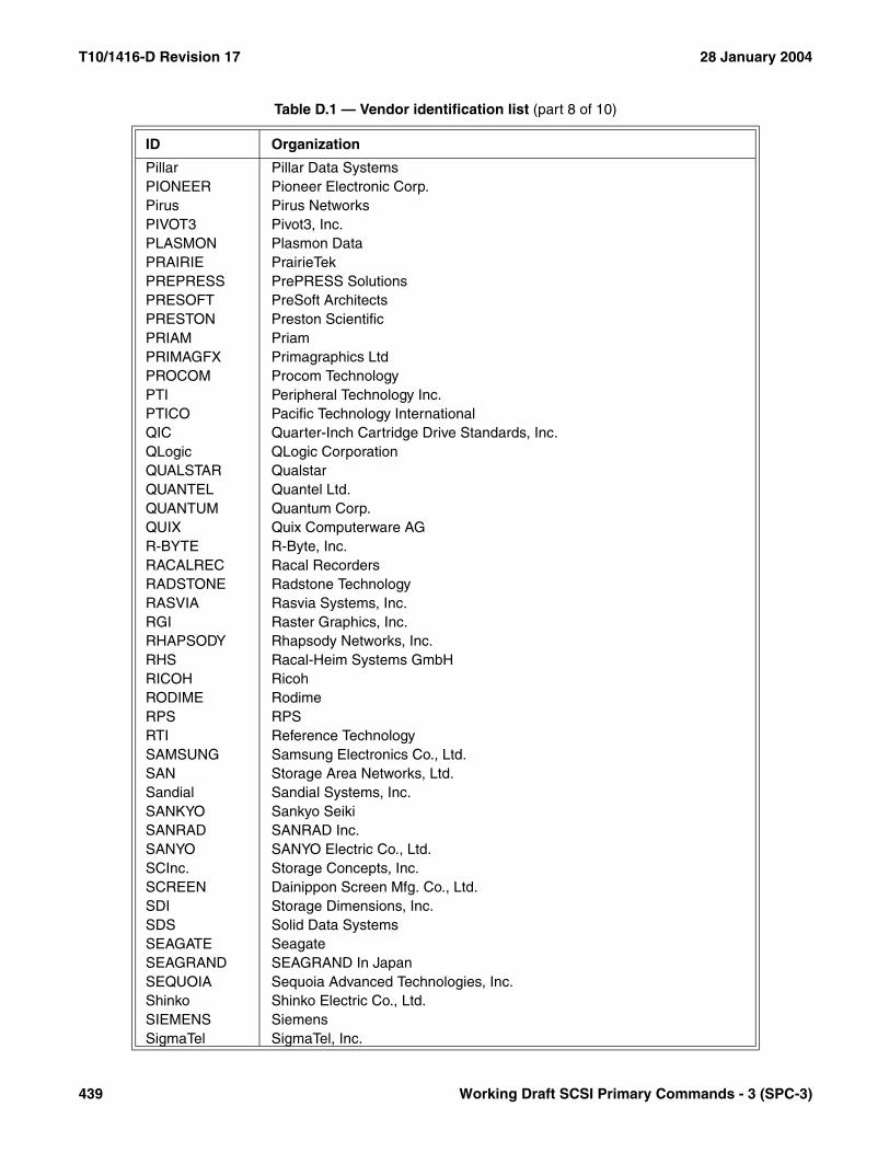
T10/1416-D Revision 17 28 January 2004
Pillar Pillar Data SystemsPIONEER Pioneer Electronic Corp.Pirus Pirus NetworksPIVOT3 Pivot3, Inc.PLASMON Plasmon DataPRAIRIE PrairieTekPREPRESS PrePRESS SolutionsPRESOFT PreSoft ArchitectsPRESTON Preston ScientificPRIAM PriamPRIMAGFX Primagraphics LtdPROCOM Procom TechnologyPTI Peripheral Technology Inc.PTICO Pacific Technology InternationalQIC Quarter-Inch Cartridge Drive Standards, Inc.QLogic QLogic CorporationQUALSTAR QualstarQUANTEL Quantel Ltd.QUANTUM Quantum Corp.QUIX Quix Computerware AGR-BYTE R-Byte, Inc.RACALREC Racal RecordersRADSTONE Radstone TechnologyRASVIA Rasvia Systems, Inc.RGI Raster Graphics, Inc.RHAPSODY Rhapsody Networks, Inc.RHS Racal-Heim Systems GmbHRICOH RicohRODIME RodimeRPS RPSRTI Reference TechnologySAMSUNG Samsung Electronics Co., Ltd.SAN Storage Area Networks, Ltd.Sandial Sandial Systems, Inc.SANKYO Sankyo SeikiSANRAD SANRAD Inc.SANYO SANYO Electric Co., Ltd.SCInc. Storage Concepts, Inc.SCREEN Dainippon Screen Mfg. Co., Ltd.SDI Storage Dimensions, Inc.SDS Solid Data SystemsSEAGATE SeagateSEAGRAND SEAGRAND In JapanSEQUOIA Sequoia Advanced Technologies, Inc.Shinko Shinko Electric Co., Ltd.SIEMENS SiemensSigmaTel SigmaTel, Inc.
Table D.1 — Vendor identification list (part 8 of 10)
ID Organization
439 Working Draft SCSI Primary Commands - 3 (SPC-3)
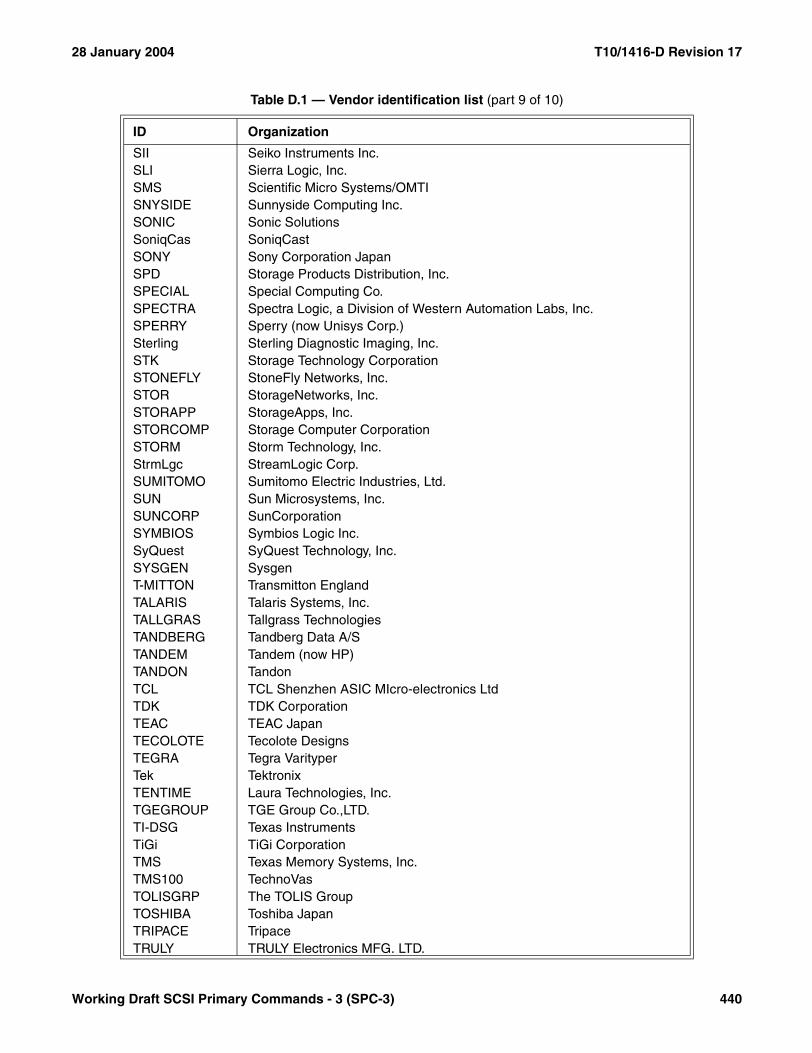
28 January 2004 T10/1416-D Revision 17
SII Seiko Instruments Inc.SLI Sierra Logic, Inc.SMS Scientific Micro Systems/OMTISNYSIDE Sunnyside Computing Inc.SONIC Sonic SolutionsSoniqCas SoniqCastSONY Sony Corporation JapanSPD Storage Products Distribution, Inc.SPECIAL Special Computing Co.SPECTRA Spectra Logic, a Division of Western Automation Labs, Inc.SPERRY Sperry (now Unisys Corp.)Sterling Sterling Diagnostic Imaging, Inc.STK Storage Technology CorporationSTONEFLY StoneFly Networks, Inc.STOR StorageNetworks, Inc.STORAPP StorageApps, Inc.STORCOMP Storage Computer CorporationSTORM Storm Technology, Inc.StrmLgc StreamLogic Corp.SUMITOMO Sumitomo Electric Industries, Ltd.SUN Sun Microsystems, Inc.SUNCORP SunCorporationSYMBIOS Symbios Logic Inc.SyQuest SyQuest Technology, Inc.SYSGEN SysgenT-MITTON Transmitton EnglandTALARIS Talaris Systems, Inc.TALLGRAS Tallgrass TechnologiesTANDBERG Tandberg Data A/STANDEM Tandem (now HP)TANDON TandonTCL TCL Shenzhen ASIC MIcro-electronics LtdTDK TDK CorporationTEAC TEAC JapanTECOLOTE Tecolote DesignsTEGRA Tegra VarityperTek TektronixTENTIME Laura Technologies, Inc.TGEGROUP TGE Group Co.,LTD.TI-DSG Texas InstrumentsTiGi TiGi CorporationTMS Texas Memory Systems, Inc.TMS100 TechnoVasTOLISGRP The TOLIS GroupTOSHIBA Toshiba JapanTRIPACE TripaceTRULY TRULY Electronics MFG. LTD.
Table D.1 — Vendor identification list (part 9 of 10)
ID Organization
Working Draft SCSI Primary Commands - 3 (SPC-3) 440
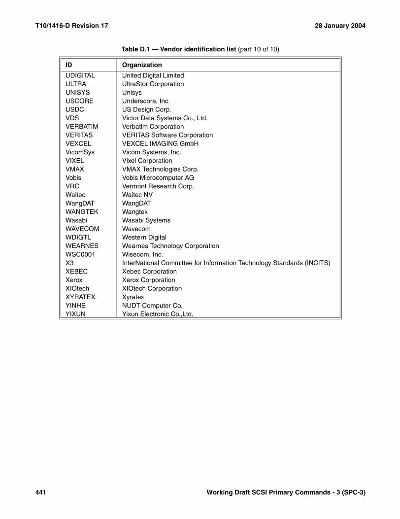
T10/1416-D Revision 17 28 January 2004
UDIGITAL United Digital LimitedULTRA UltraStor CorporationUNISYS UnisysUSCORE Underscore, Inc.USDC US Design Corp.VDS Victor Data Systems Co., Ltd.VERBATIM Verbatim CorporationVERITAS VERITAS Software CorporationVEXCEL VEXCEL IMAGING GmbHVicomSys Vicom Systems, Inc.VIXEL Vixel CorporationVMAX VMAX Technologies Corp.Vobis Vobis Microcomputer AGVRC Vermont Research Corp.Waitec Waitec NVWangDAT WangDATWANGTEK WangtekWasabi Wasabi SystemsWAVECOM WavecomWDIGTL Western DigitalWEARNES Wearnes Technology CorporationWSC0001 Wisecom, Inc.X3 InterNational Committee for Information Technology Standards (INCITS)XEBEC Xebec CorporationXerox Xerox CorporationXIOtech XIOtech CorporationXYRATEX XyratexYINHE NUDT Computer Co.YIXUN Yixun Electronic Co.,Ltd.
Table D.1 — Vendor identification list (part 10 of 10)
ID Organization
441 Working Draft SCSI Primary Commands - 3 (SPC-3)

28 January 2004 T10/1416-D revision Revision 17
Working Draft SCSI Primary Commands - 3 (SPC-3) 442
Annex E(informative)
Bibliography
E.1 EUI-48 (Extended Unique Identifier, a 48-bit globally unique identifier): The IEEE maintains a tutor ialdescribing EUI-48 at http://standards.ieee.org/regauth/oui/tutorials/EUI48.html.
E.2 EUI-64 (Extended Unique Identifier, a 64-bit globally unique identifier): The IEEE maintains a tutor ialdescribing EUI-64 at http://standards.ieee.org/regauth/oui/tutorials/EUI64.html.
E.3 OUI (Organizationally Unique Identifier): The OUI is also known as the IEEE company_id. The IEEEmaintains a tutorial describing the OUI at http://standards.ieee.org/regauth/oui/.
E.4 URI Schemes: The Internet Assigned Numbers Authority maintains a list of schemes for URI and URL namesat http://www.iana.org/assignments/uri-schemes.
E.5 TCP/UDP port numbers: The Internet Assigned Numbers Authority maintains a list of port numbers for theTCP and UDP protocols at http://www.iana.org/assignments/port-numbers.