Embed Size (px)
Citation preview
Workshop ‘Structural Fire Design of Buildings according to the Eurocodes’ – Brussels, 27-28 November 2012 1
Fire resistance assessment of composite
steel-concrete structures Basic design methods Worked examples
CAJOT Louis-Guy
CEN/TC250 EG-EN1994-1-2 Convenor ArcelorMittal
email: [email protected]
Workshop ‘Structural Fire Design of Buildings according to the Eurocodes’ – Brussels, 27-28 November 2012 2
Fire resistance assessment of composite steel-concrete structures
Basic design methods of EN1994-1-2
Fire part of Eurocode 4
Workshop ‘Structural Fire Design of Buildings according to the Eurocodes’ – Brussels, 27-28 November 2012 3
Fire parts of Eurocodes 2 to 6 and 9
Following common layout to provide design rules for fire resistance of various types of structures: General Scope, application field, definitions, symbols and units
Basic principles Performances requirements, design values of material properties
and assessment approaches Material properties Mechanical and thermal properties at elevated temperatures
Assessment methods for fire resistance Constructional details Annexes Additional information: common case - more detailed design rules
Workshop ‘Structural Fire Design of Buildings according to the Eurocodes’ – Brussels, 27-28 November 2012 4
Scope of fire part of Eurocode 4
Load bearing function R of composite structures is covered by the design rules of the fire part of Eurocode 4 •Load bearing function of a structure is satisfied only if during the relevant of fire exposure t
Efi,d,t ≤ Rfi,d,t
where Efi,d,t : design effect of actions (Eurocodes 0 and 1) Rfi,d,t : corresponding design resistance of the structure at instant t
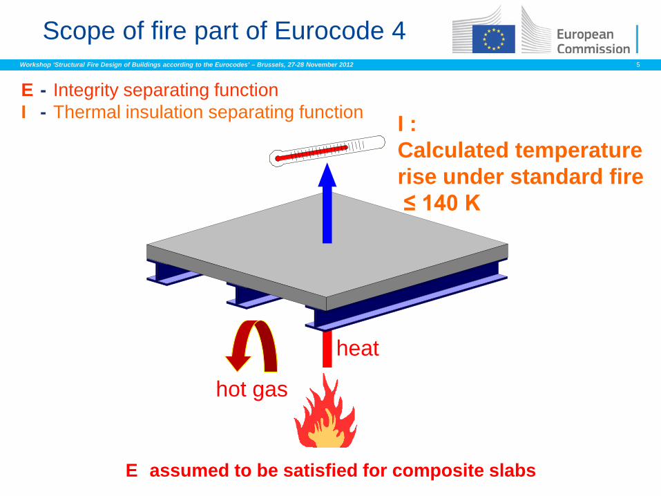
• In addition, for elements ensuring compartmentation, the separating function has to be maintained during the relevant fire exposure t
→ Integrity E
→ Thermal insulation I
Workshop ‘Structural Fire Design of Buildings according to the Eurocodes’ – Brussels, 27-28 November 2012 5
hot gas
heat
E - Integrity separating function I - Thermal insulation separating function I :
Calculated temperature rise under standard fire ≤ 140 K
E assumed to be satisfied for composite slabs
Scope of fire part of Eurocode 4
Workshop ‘Structural Fire Design of Buildings according to the Eurocodes’ – Brussels, 27-28 November 2012 6
Scope of fire part of Eurocode 4
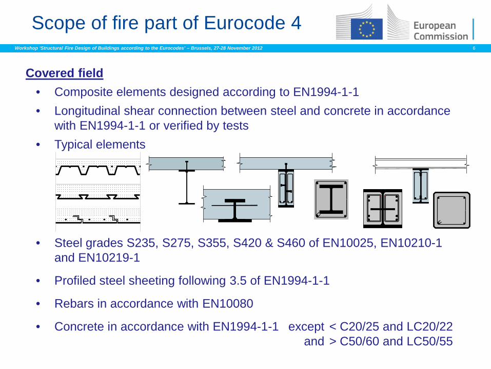
Covered field • Composite elements designed according to EN1994-1-1 • Longitudinal shear connection between steel and concrete in accordance
with EN1994-1-1 or verified by tests • Typical elements
• Steel grades S235, S275, S355, S420 & S460 of EN10025, EN10210-1 and EN10219-1
• Profiled steel sheeting following 3.5 of EN1994-1-1
• Rebars in accordance with EN10080
• Concrete in accordance with EN1994-1-1 except < C20/25 and LC20/22 and > C50/60 and LC50/55
Workshop ‘Structural Fire Design of Buildings according to the Eurocodes’ – Brussels, 27-28 November 2012 7
Application of EC4 for fire resistance assessment – basic knowledge
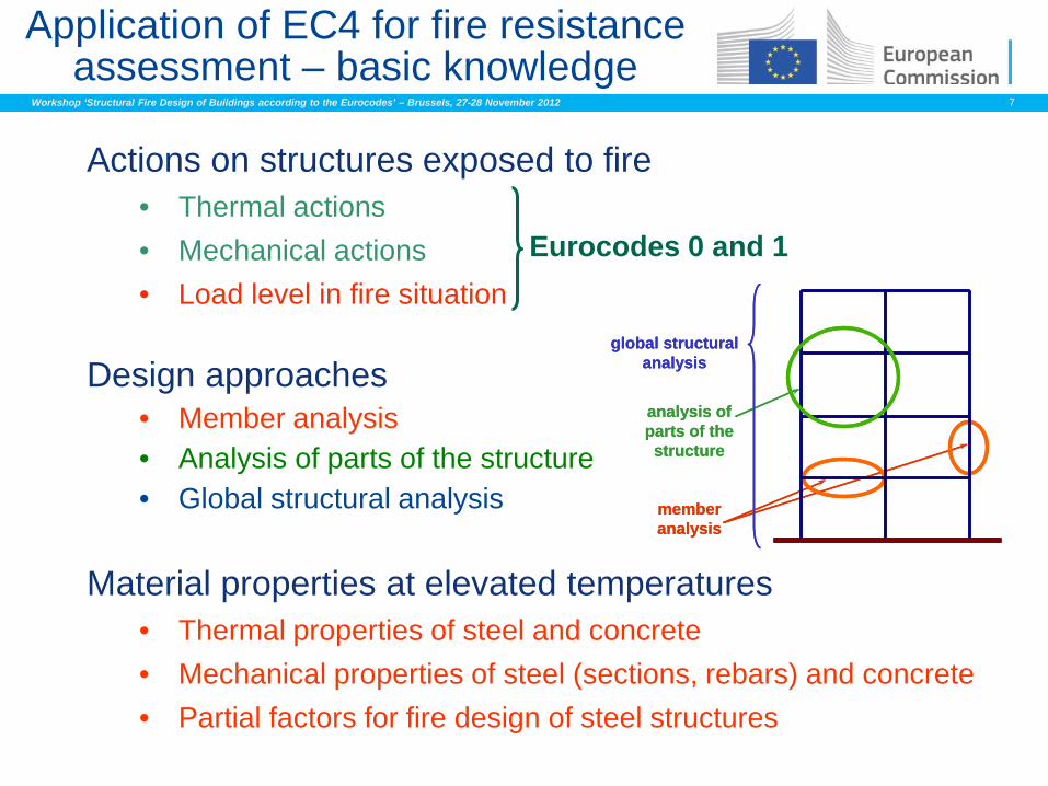
Actions on structures exposed to fire • Thermal actions • Mechanical actions • Load level in fire situation
Design approaches • Member analysis • Analysis of parts of the structure • Global structural analysis
Material properties at elevated temperatures • Thermal properties of steel and concrete • Mechanical properties of steel (sections, rebars) and concrete • Partial factors for fire design of steel structures
Eurocodes 0 and 1
global structuralanalysis
member analysis
analysis of parts of the structure
global structuralanalysis
member analysis
analysis of parts of the structure
Workshop ‘Structural Fire Design of Buildings according to the Eurocodes’ – Brussels, 27-28 November 2012 8
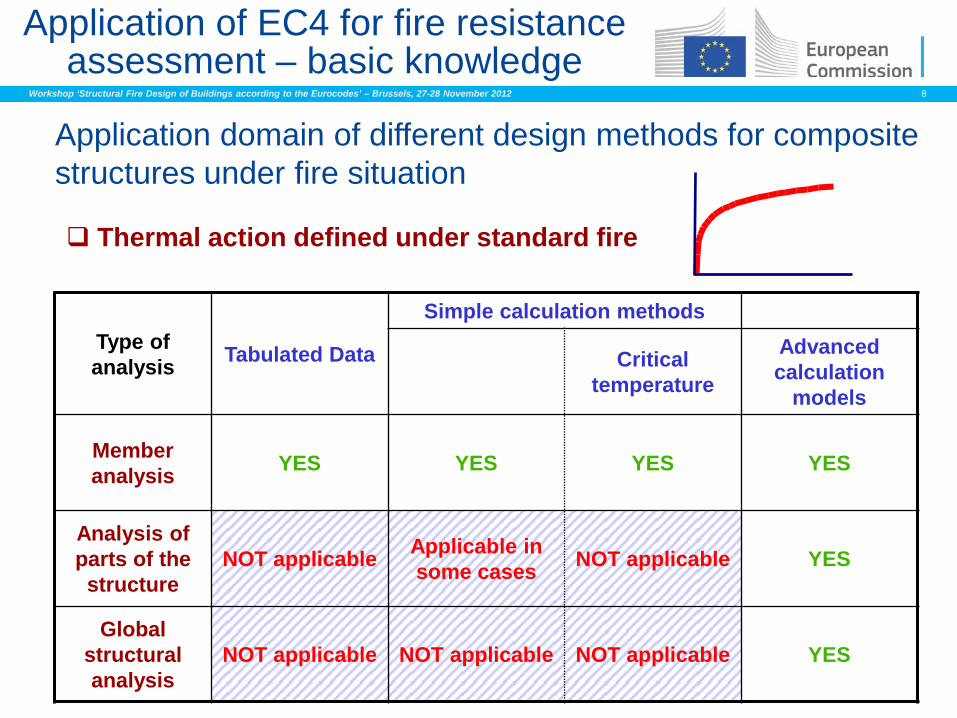
Application domain of different design methods for composite structures under fire situation
Thermal action defined under standard fire
Application of EC4 for fire resistance assessment – basic knowledge
Type of analysis Tabulated Data
Simple calculation methods
Critical temperature
Advanced calculation
models
Member analysis YES YES YES YES
Analysis of parts of the structure
NOT applicable Applicable in some cases NOT applicable YES
Global structural analysis
NOT applicable NOT applicable NOT applicable YES
Workshop ‘Structural Fire Design of Buildings according to the Eurocodes’ – Brussels, 27-28 November 2012 9
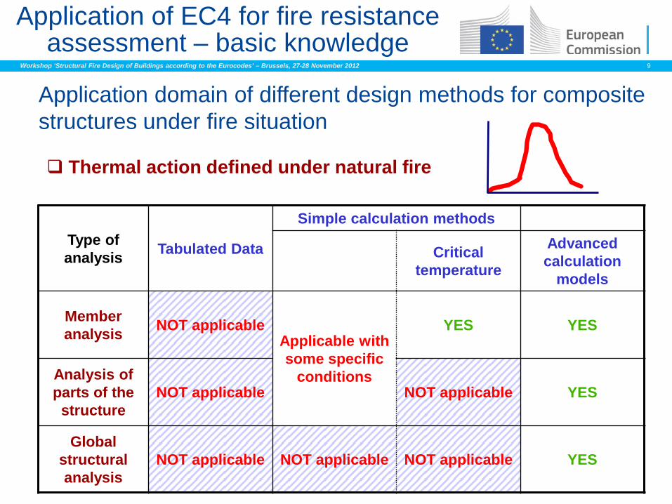
Thermal action defined under natural fire
Application of EC4 for fire resistance assessment – basic knowledge
Application domain of different design methods for composite structures under fire situation
Type of analysis Tabulated Data
Simple calculation methods
Critical temperature
Advanced calculation
models
Member analysis NOT applicable
Applicable with some specific
conditions
YES YES
Analysis of parts of the structure
NOT applicable NOT applicable YES
Global structural analysis
NOT applicable NOT applicable NOT applicable YES
Workshop ‘Structural Fire Design of Buildings according to the Eurocodes’ – Brussels, 27-28 November 2012 10
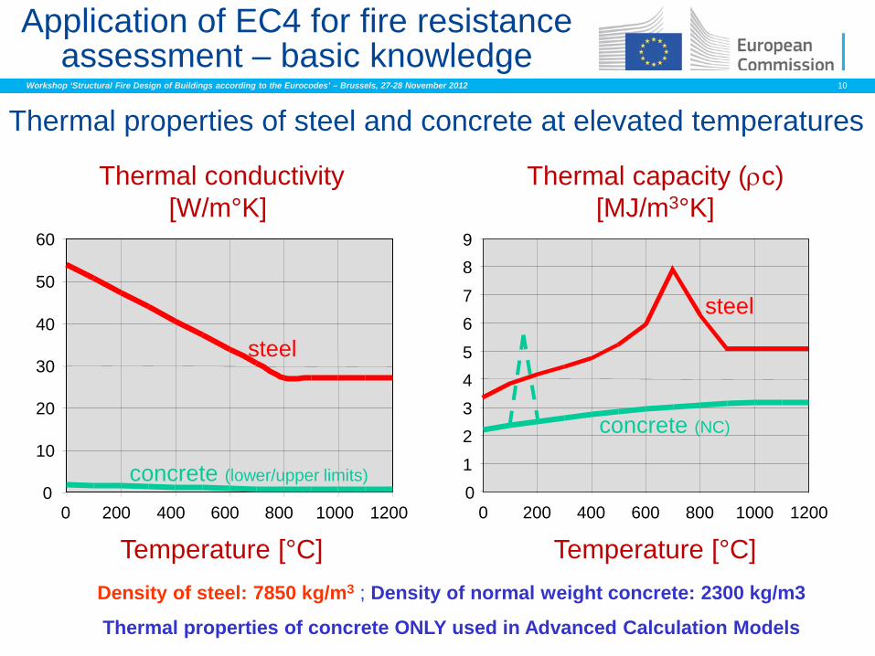
Thermal properties of steel and concrete at elevated temperatures
Density of steel: 7850 kg/m3 ; Density of normal weight concrete: 2300 kg/m3
Application of EC4 for fire resistance assessment – basic knowledge
Thermal conductivity [W/m°K]
Temperature [°C]
0
10
20
30
40
50
60
0 200 400 600 800 1000 1200
steel
concrete (lower/upper limits) 0 1 2 3 4 5
6 7
8 9
0 200 400 600 800 1000 1200
steel
concrete (NC)
Thermal capacity (ρc) [MJ/m3°K]
Temperature [°C]
Thermal properties of concrete ONLY used in Advanced Calculation Models
Workshop ‘Structural Fire Design of Buildings according to the Eurocodes’ – Brussels, 27-28 November 2012 11
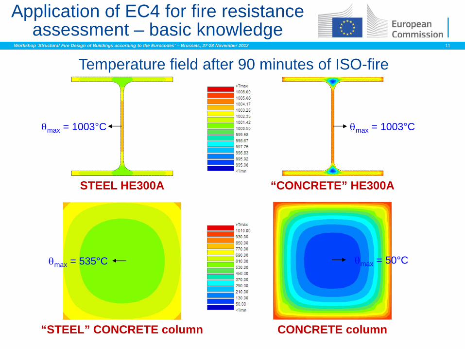
Application of EC4 for fire resistance assessment – basic knowledge
Temperature field after 90 minutes of ISO-fire
“CONCRETE” HE300A
θmax = 1003°C
“STEEL” CONCRETE column
θmax = 535°C
θmax = 1003°C
STEEL HE300A
CONCRETE column
θmax = 50°C
Workshop ‘Structural Fire Design of Buildings according to the Eurocodes’ – Brussels, 27-28 November 2012 12
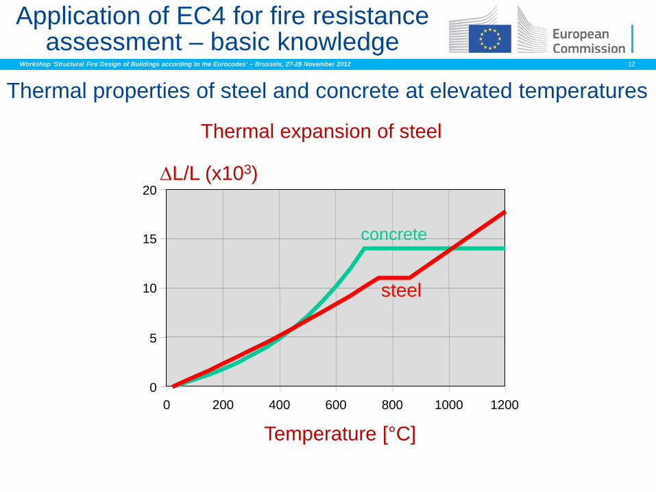
Thermal expansion of steel
0
5
10
15
20
0 200 400 600 800 1000 1200
∆L/L (x103)
Thermal properties of steel and concrete at elevated temperatures
Application of EC4 for fire resistance assessment – basic knowledge
Temperature [°C]
steel
concrete
Workshop ‘Structural Fire Design of Buildings according to the Eurocodes’ – Brussels, 27-28 November 2012 13
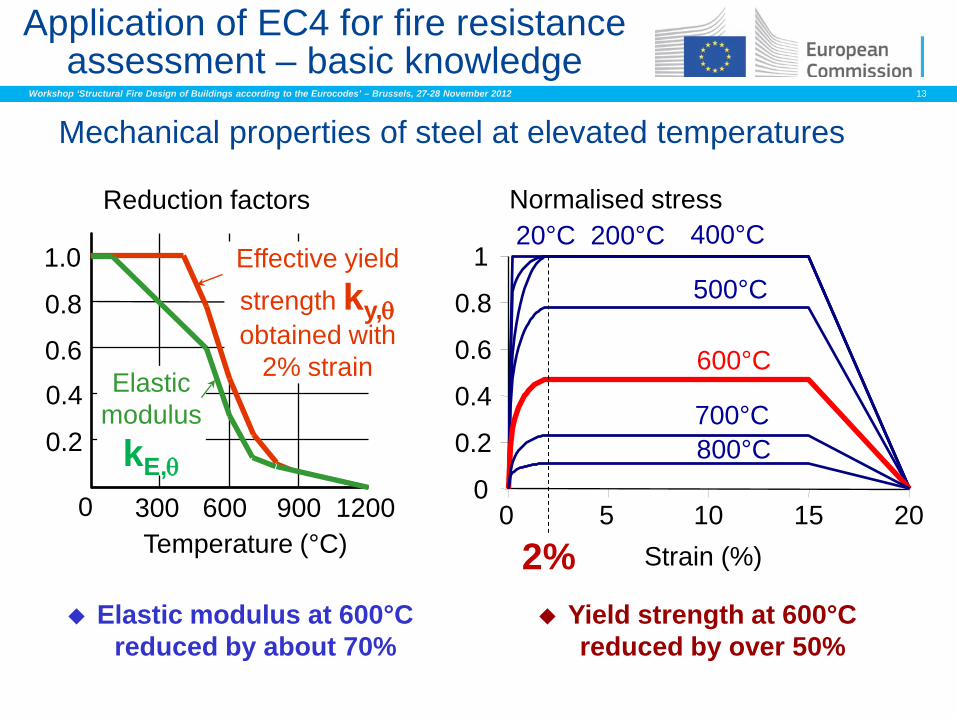
Mechanical properties of steel at elevated temperatures
Elastic modulus at 600°C reduced by about 70%
Yield strength at 600°C reduced by over 50%
0 300 600 900 1200
1.0
0.8
0.6
0.4
0.2
Reduction factors
Temperature (°C)
Effective yield strength ky,θ obtained with
2% strain Elastic modulus
kE,θ
Normalised stress
Strain (%)
20°C 200°C 400°C
500°C
600°C
700°C 800°C
0
0.2
0.4
0.6
0.8
1
0 5 10 15 20
2%
Application of EC4 for fire resistance assessment – basic knowledge
Workshop ‘Structural Fire Design of Buildings according to the Eurocodes’ – Brussels, 27-28 November 2012 14
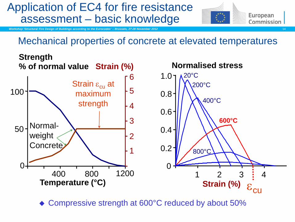
Mechanical properties of concrete at elevated temperatures
Application of EC4 for fire resistance assessment – basic knowledge
Compressive strength at 600°C reduced by about 50%
600°C
20°C
Strain (%)
Normalised stress
εcu
200°C
400°C
800°C
1 2 3 4
1.0
0.8
0.6
0.4
0.2
0
Temperature (°C)
Strain (%) % of normal value
Strain εcu at maximum strength
Normal-weight Concrete
Strength
6
5
4
3
2
1
100
50
0 400 800 1200
Workshop ‘Structural Fire Design of Buildings according to the Eurocodes’ – Brussels, 27-28 November 2012 15
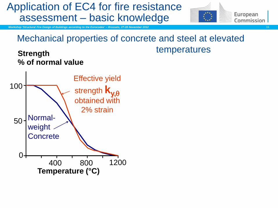
Mechanical properties of concrete and steel at elevated temperatures
Application of EC4 for fire resistance assessment – basic knowledge
Temperature (°C)
% of normal value
Normal-weight Concrete
Strength
100
50
0 400 800 1200
Effective yield strength ky,θ obtained with
2% strain
Workshop ‘Structural Fire Design of Buildings according to the Eurocodes’ – Brussels, 27-28 November 2012 16
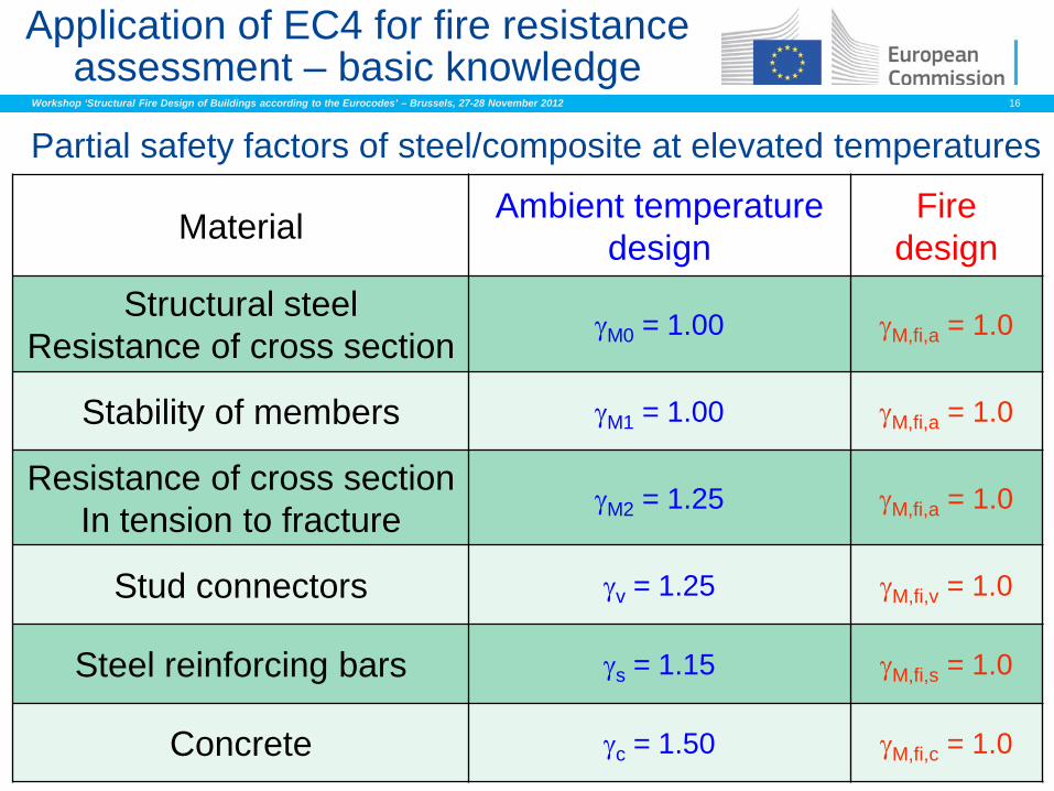
Partial safety factors of steel/composite at elevated temperatures
Material Ambient temperature design
Fire design
Structural steel Resistance of cross section γM0 = 1.00 γM,fi,a = 1.0
Stability of members γM1 = 1.00 γM,fi,a = 1.0
Resistance of cross section In tension to fracture γM2 = 1.25 γM,fi,a = 1.0
Stud connectors γv = 1.25 γM,fi,v = 1.0
Steel reinforcing bars γs = 1.15 γM,fi,s = 1.0
Concrete γc = 1.50 γM,fi,c = 1.0
Application of EC4 for fire resistance assessment – basic knowledge
Workshop ‘Structural Fire Design of Buildings according to the Eurocodes’ – Brussels, 27-28 November 2012 17
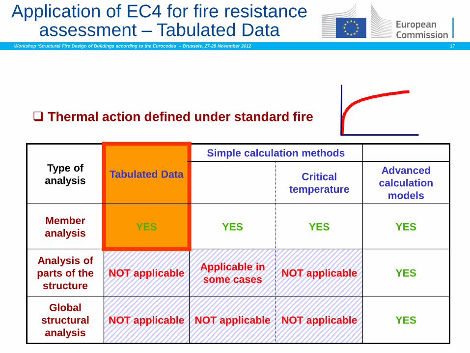
Thermal action defined under standard fire
Application of EC4 for fire resistance assessment – Tabulated Data
Type of analysis Tabulated Data
Simple calculation methods
Critical temperature
Advanced calculation
models
Member analysis YES YES YES YES
Analysis of parts of the structure
NOT applicable Applicable in some cases NOT applicable YES
Global structural analysis
NOT applicable NOT applicable NOT applicable YES
Workshop ‘Structural Fire Design of Buildings according to the Eurocodes’ – Brussels, 27-28 November 2012 18
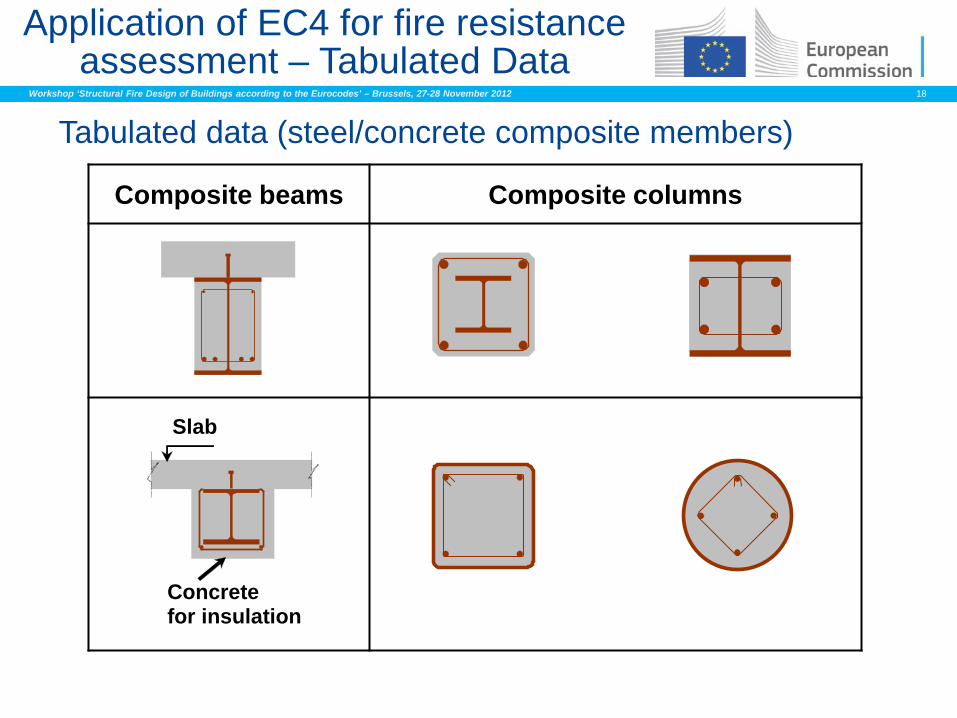
Application of EC4 for fire resistance assessment – Tabulated Data
Tabulated data (steel/concrete composite members)
Composite beams Composite columns
Concrete for insulation
Slab
Workshop ‘Structural Fire Design of Buildings according to the Eurocodes’ – Brussels, 27-28 November 2012 19
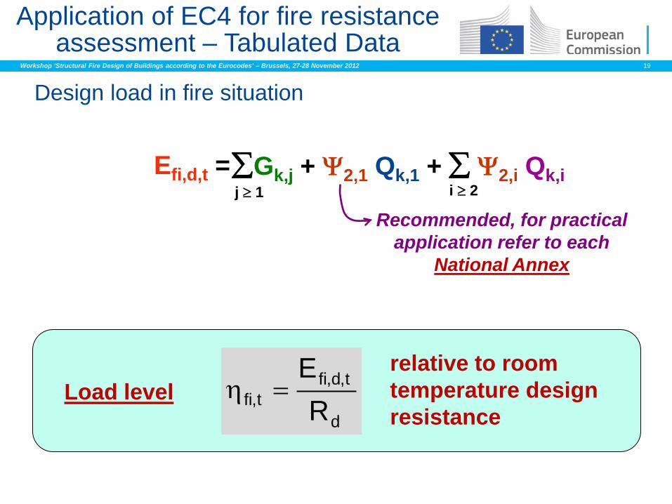
Design load in fire situation
∑Gk,j + Ψ2,1 Qk,1 + ∑ Ψ2,i Qk,i j ≥ 1 i ≥ 2
Efi,d,t =
Recommended, for practical application refer to each
National Annex
relative to room temperature design resistance d
t,d,fit,fi R
E=ηLoad level
Application of EC4 for fire resistance assessment – Tabulated Data
Workshop ‘Structural Fire Design of Buildings according to the Eurocodes’ – Brussels, 27-28 November 2012 20
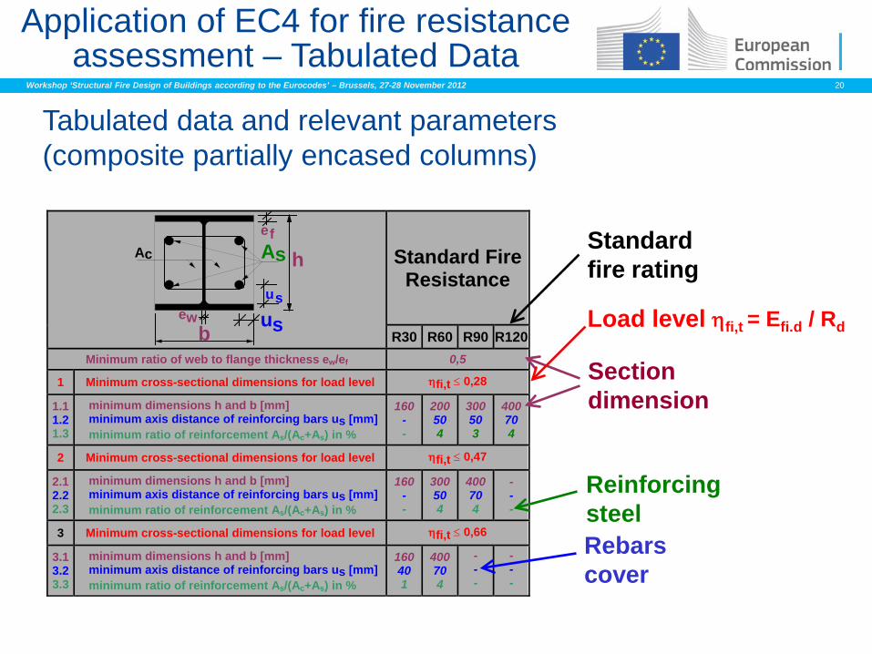
Tabulated data and relevant parameters (composite partially encased columns)
Standard Fire Resistance
c A s
u s u s
w
e f
e b
A h
R30 R60 R90 R120 Minimum ratio of web to flange thickness ew/ef 0,5
1 Minimum cross-sectional dimensions for load level ηfi,t ≤ 0,28
1.1 1.2 1.3
minimum dimensions h and b [mm] minimum axis distance of reinforcing bars us [mm] minimum ratio of reinforcement As/(Ac+As) in %
160 - -
200 50 4
300 50 3
400 70 4
2 Minimum cross-sectional dimensions for load level ηfi,t ≤ 0,47
2.1 2.2 2.3
minimum dimensions h and b [mm] minimum axis distance of reinforcing bars us [mm] minimum ratio of reinforcement As/(Ac+As) in %
160 - -
300 50 4
400 70 4
- - -
3 Minimum cross-sectional dimensions for load level ηfi,t ≤ 0,66
3.1 3.2 3.3
minimum dimensions h and b [mm] minimum axis distance of reinforcing bars us [mm] minimum ratio of reinforcement As/(Ac+As) in %
160 40 1
400 70 4
- - -
- - -
Standard fire rating
Section dimension
Rebars cover
Reinforcing steel
Load level ηfi,t = Efi.d / Rd
Application of EC4 for fire resistance assessment – Tabulated Data
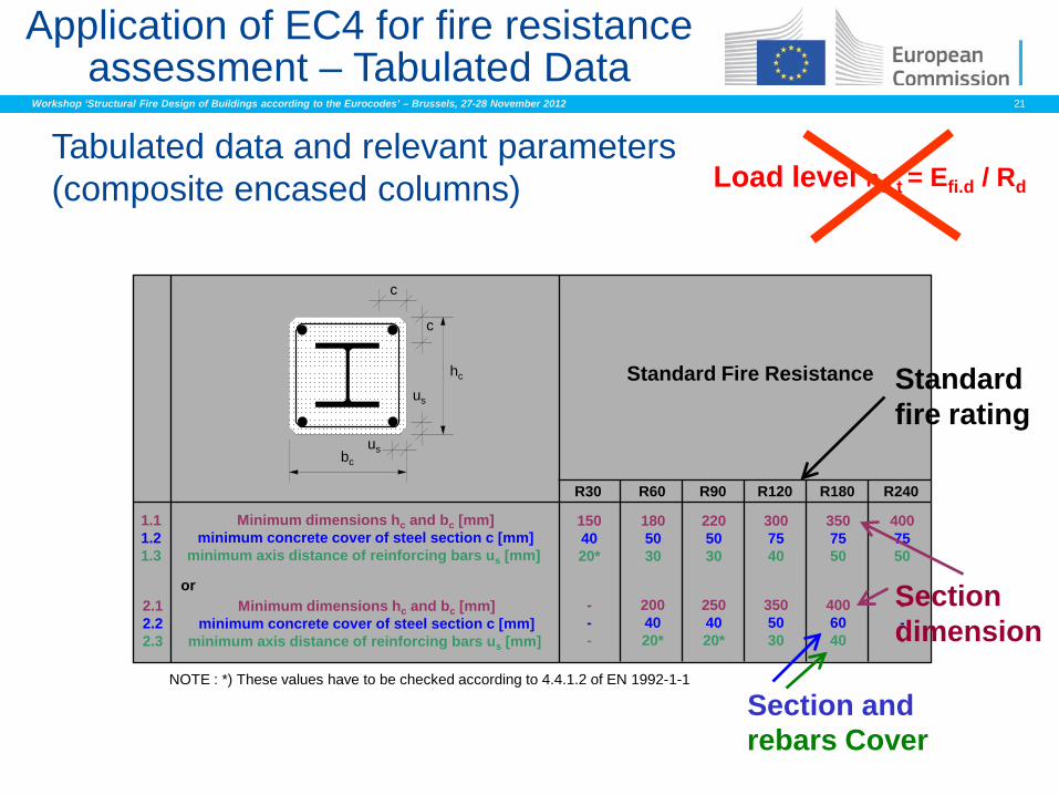
Workshop ‘Structural Fire Design of Buildings according to the Eurocodes’ – Brussels, 27-28 November 2012 21
bc
us
us
hc
c
c
Standard Fire Resistance
R30 R60 R90 R120 R180 R240
1.1 1.2 1.3
or 2.1 2.2 2.3
- - -
NOTE : *) These values have to be checked according to 4.4.1.2 of EN 1992-1-1
Minimum dimensions hc and bc [mm] minimum concrete cover of steel section c [mm]
minimum axis distance of reinforcing bars us [mm]
Minimum dimensions hc and bc [mm] minimum concrete cover of steel section c [mm]
minimum axis distance of reinforcing bars us [mm]
150 40 20*
180 50 30
220 50 30
300 75 40
350 75 50
400 75 50
200 40 20*
250 40 20*
350 50 30
400 60 40
- - -
Tabulated data and relevant parameters (composite encased columns)
Standard fire rating
Section dimension
Load level ηfi,t = Efi.d / Rd
Section and
Application of EC4 for fire resistance assessment – Tabulated Data
rebars Cover
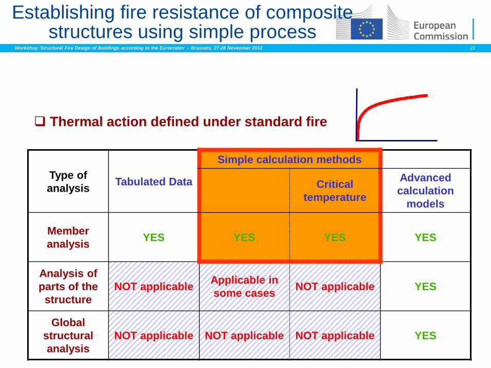
Workshop ‘Structural Fire Design of Buildings according to the Eurocodes’ – Brussels, 27-28 November 2012 22
Thermal action defined under standard fire
Type of analysis Tabulated Data
Simple calculation methods
Critical temperature
Advanced calculation
models
Member analysis YES YES YES YES
Analysis of parts of the structure
NOT applicable Applicable in some cases NOT applicable YES
Global structural analysis
NOT applicable NOT applicable NOT applicable YES
Establishing fire resistance of composite structures using simple process
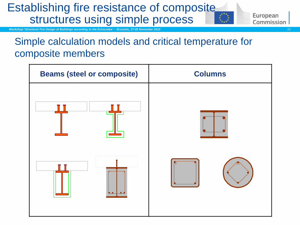
Workshop ‘Structural Fire Design of Buildings according to the Eurocodes’ – Brussels, 27-28 November 2012 23
Simple calculation models and critical temperature for composite members
Beams (steel or composite) Columns
Establishing fire resistance of composite structures using simple process
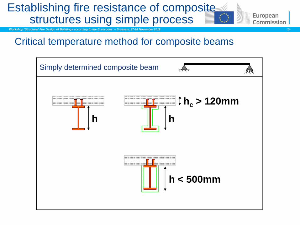
Workshop ‘Structural Fire Design of Buildings according to the Eurocodes’ – Brussels, 27-28 November 2012 24
Critical temperature method for composite beams
Simply determined composite beam
h
hc > 120mm
Establishing fire resistance of composite structures using simple process
h < 500mm
h
Workshop ‘Structural Fire Design of Buildings according to the Eurocodes’ – Brussels, 27-28 November 2012 25
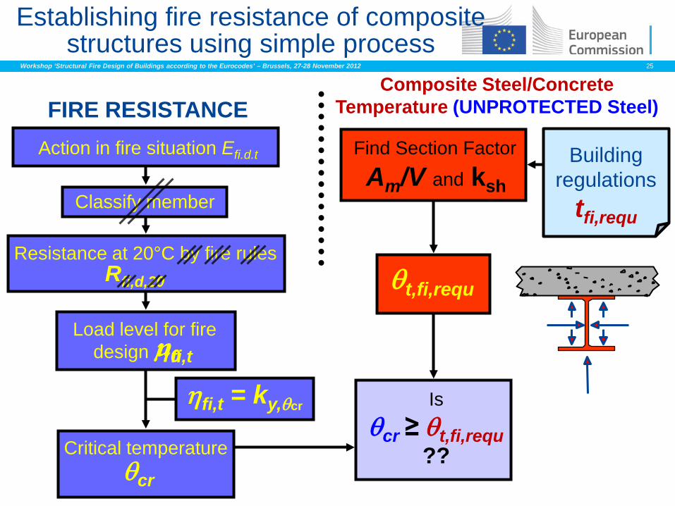
Action in fire situation Efi.d.t
FIRE RESISTANCE
Building regulations
tfi,requ Classify member
Load level for fire design ηfi,t
Resistance at 20°C by fire rules Rfi,d,20
Critical temperature θcr
Find Section Factor
Am/V and ksh
Is θcr ≥ θt,fi,requ
??
Composite Steel/Concrete Temperature (UNPROTECTED Steel)
θt,fi,requ
ηfi,t = ky,θcr
Establishing fire resistance of composite structures using simple process
µ0
Workshop ‘Structural Fire Design of Buildings according to the Eurocodes’ – Brussels, 27-28 November 2012 26
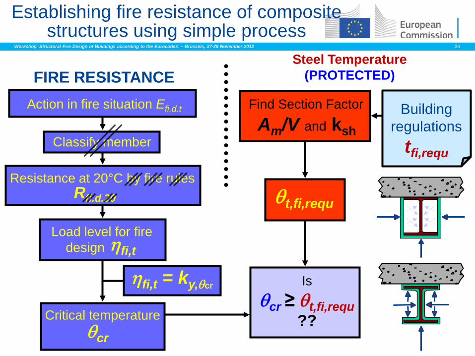
Action in fire situation Efi.d.t
FIRE RESISTANCE
Building regulations
tfi,requ Classify member
Load level for fire design ηfi,t
Resistance at 20°C by fire rules Rfi.d.20
Critical temperature θcr
Find Section Factor
Am/V and ksh
Is θcr ≥ θt,fi,requ
??
Steel Temperature (PROTECTED)
θt,fi,requ
ηfi,t = ky,θcr
Establishing fire resistance of composite structures using simple process
Workshop ‘Structural Fire Design of Buildings according to the Eurocodes’ – Brussels, 27-28 November 2012 27
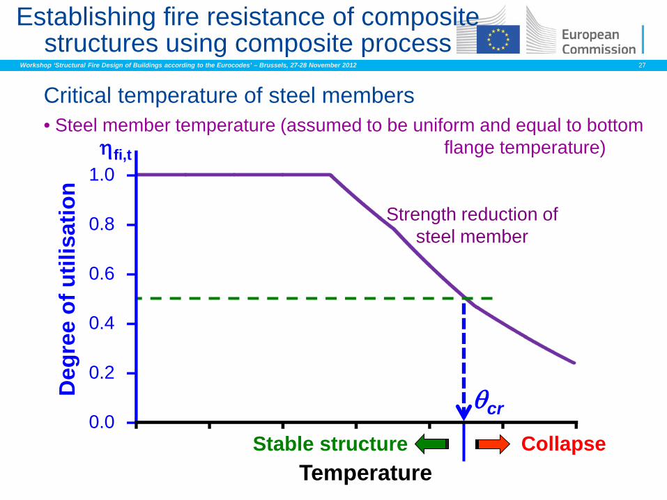
Critical temperature of steel members • Steel member temperature (assumed to be uniform and equal to bottom flange temperature)
Temperature
θcr
Collapse
Strength reduction of steel member
Stable structure
Establishing fire resistance of composite structures using composite process
ηfi,t
0.0
0.2
0.4
0.6
0.8
1.0
Deg
ree
of u
tilis
atio
n
Workshop ‘Structural Fire Design of Buildings according to the Eurocodes’ – Brussels, 27-28 November 2012 28
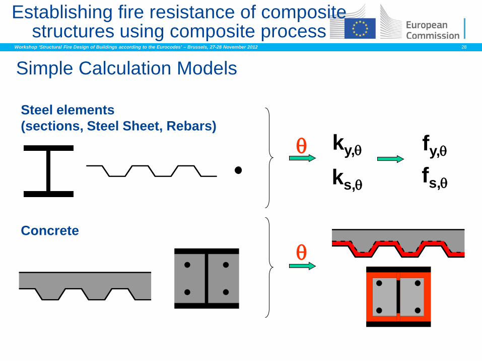
Simple Calculation Models
Steel elements (sections, Steel Sheet, Rebars)
Concrete
θ ky,θ fy,θ
θ
Establishing fire resistance of composite structures using composite process
ks,θ fs,θ
Workshop ‘Structural Fire Design of Buildings according to the Eurocodes’ – Brussels, 27-28 November 2012 29
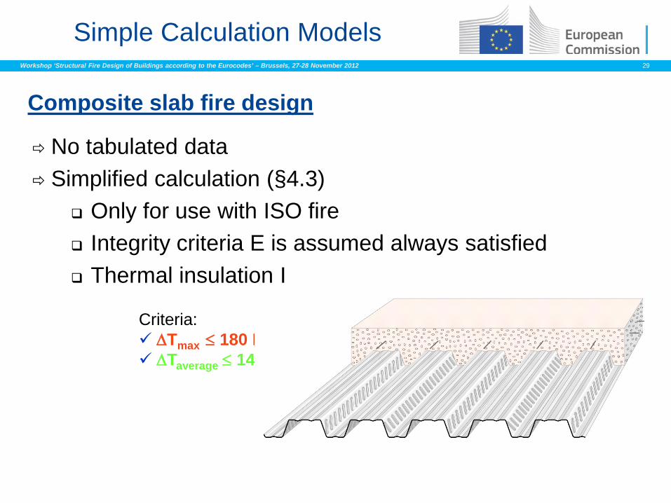
Simple Calculation Models
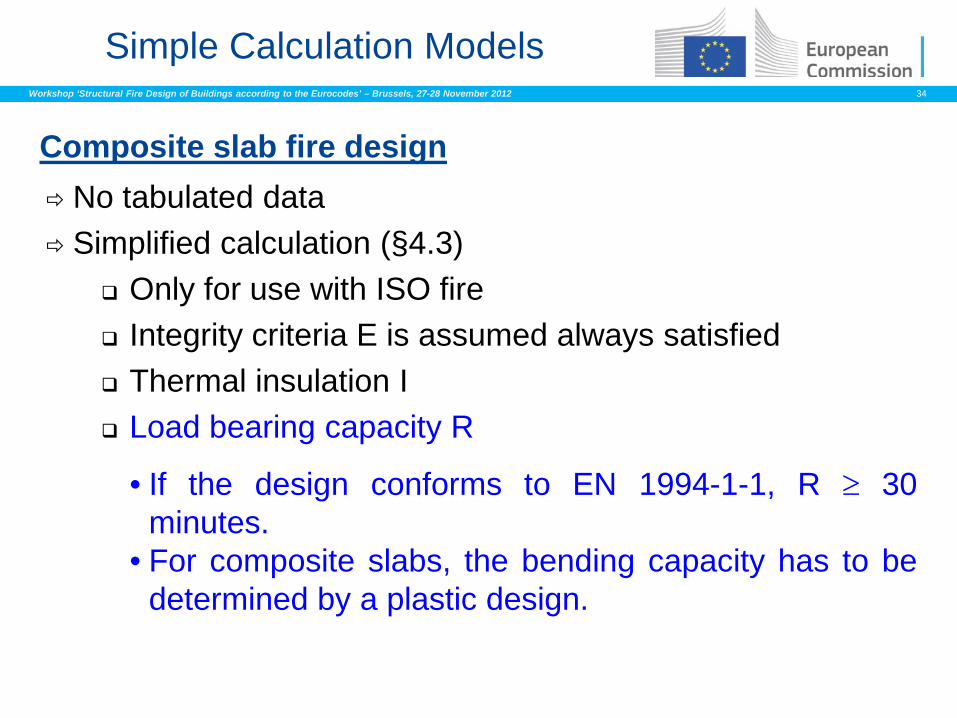
No tabulated data Simplified calculation (§4.3)
Only for use with ISO fire Integrity criteria E is assumed always satisfied Thermal insulation I
Composite slab fire design
Criteria: ∆Tmax ≤ 180 K ∆Taverage ≤ 140 K
Workshop ‘Structural Fire Design of Buildings according to the Eurocodes’ – Brussels, 27-28 November 2012 30
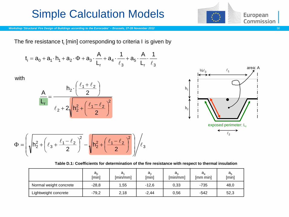
Simple Calculation Models
The fire resistance ti [min] corresponding to criteria I is given by
with
exposed perimeter: Lr
area: A 1
h2
h1
½3
2
3r5
34
r32110i
1LAa1a
LAaahaat
⋅⋅+⋅+⋅+Φ⋅+⋅+=
2212
22
212
r
2h2
2h
LA
−
++
+⋅
=
3
2212
2
221
322 2
h2
h
−
+−
−
++=Φ
Table D.1: Coefficients for determination of the fire resistance with respect to thermal insulation
a0 [min]
a1 [min/mm]
a2 [min]
a3 [min/mm]
a4 [mm min]
a5 [min]
Normal weight concrete -28,8 1,55 -12,6 0,33 -735 48,0
Lightweight concrete -79,2 2,18 -2,44 0,56 -542 52,3
Workshop ‘Structural Fire Design of Buildings according to the Eurocodes’ – Brussels, 27-28 November 2012 31
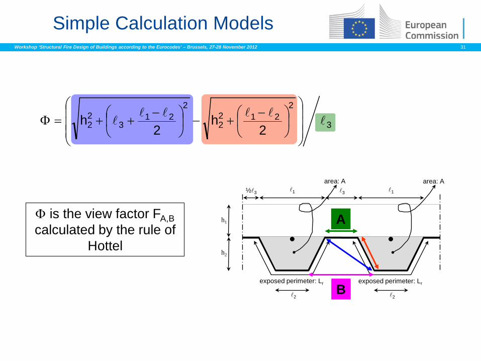
Simple Calculation Models
exposed perimeter: Lr
area: A 1 3
2
exposed perimeter: Lr
area: A 1
h2
h1
½3
2
3
2212
2
221
322 2
h2
h
−
+−
−
++=Φ
Φ is the view factor FA,B calculated by the rule of
Hottel
A
B
Workshop ‘Structural Fire Design of Buildings according to the Eurocodes’ – Brussels, 27-28 November 2012 32
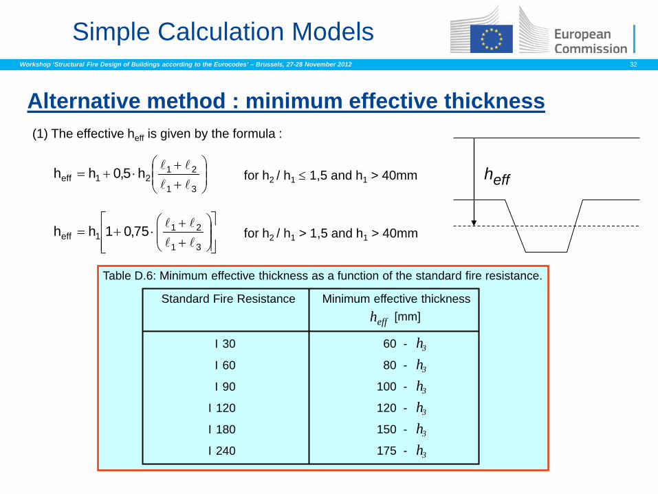
Alternative method : minimum effective thickness
Simple Calculation Models
heff
Table D.6: Minimum effective thickness as a function of the standard fire resistance.
Standard Fire Resistance Minimum effective thickness heff [mm]
I 30
I 60
I 90
I 120
I 180
I 240
60
80
100
120
150
175
- 3 h
- 3 h
- 3 h
- 3 h
- 3 h
- 3 h
(1) The effective heff is given by the formula :
++
⋅+=31
2121eff h5,0hh
++
⋅+=31
211eff 75,01hh
for h2 / h1 ≤ 1,5 and h1 > 40mm
for h2 / h1 > 1,5 and h1 > 40mm
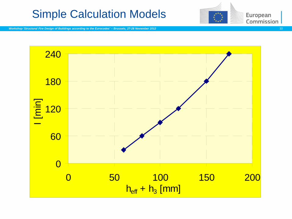
Workshop ‘Structural Fire Design of Buildings according to the Eurocodes’ – Brussels, 27-28 November 2012 33
Simple Calculation Models
0
60
120
180
240
0 50 100 150 200heff + h3 [mm]
I [m
in]
Workshop ‘Structural Fire Design of Buildings according to the Eurocodes’ – Brussels, 27-28 November 2012 34
Simple Calculation Models
No tabulated data Simplified calculation (§4.3)
Only for use with ISO fire Integrity criteria E is assumed always satisfied Thermal insulation I Load bearing capacity R
Composite slab fire design
• If the design conforms to EN 1994-1-1, R ≥ 30 minutes.
• For composite slabs, the bending capacity has to be determined by a plastic design.
Workshop ‘Structural Fire Design of Buildings according to the Eurocodes’ – Brussels, 27-28 November 2012 35
Simple Calculation Models
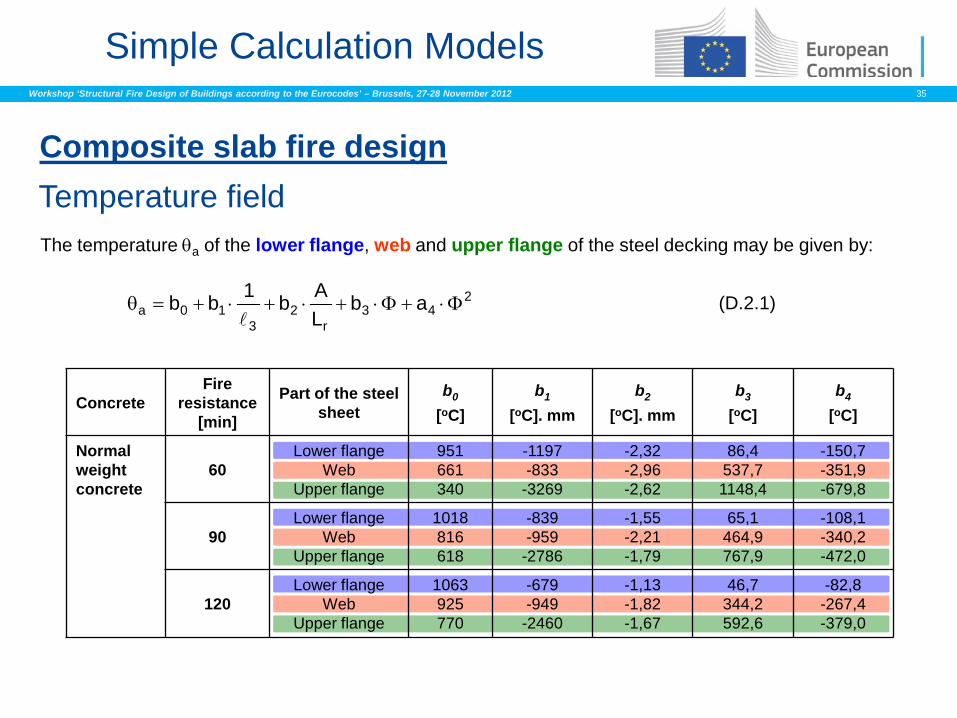
Composite slab fire design Temperature field
243
r2
310a ab
LAb1bb Φ⋅+Φ⋅+⋅+⋅+=θ
(D.2.1)
The temperature θa of the lower flange, web and upper flange of the steel decking may be given by:
Concrete Fire
resistance [min]
Part of the steel sheet
b0 [oC]
b1 [oC]. mm
b2 [oC]. mm
b3 [oC]
b4 [oC]
Normal weight concrete
60 Lower flange
Web Upper flange
951 661 340
-1197 -833
-3269
-2,32 -2,96 -2,62
86,4 537,7 1148,4
-150,7 -351,9 -679,8
90 Lower flange
Web Upper flange
1018 816 618
-839 -959
-2786
-1,55 -2,21 -1,79
65,1 464,9 767,9
-108,1 -340,2 -472,0
120 Lower flange
Web Upper flange
1063 925 770
-679 -949
-2460
-1,13 -1,82 -1,67
46,7 344,2 592,6
-82,8 -267,4 -379,0
Workshop ‘Structural Fire Design of Buildings according to the Eurocodes’ – Brussels, 27-28 November 2012 36
Simple Calculation Models
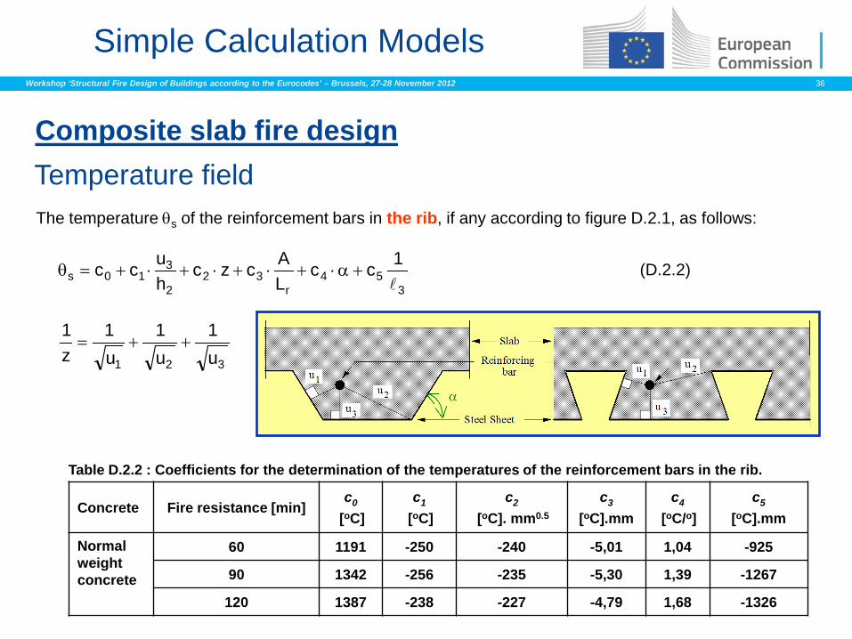
Composite slab fire design Temperature field
354
r32
2
310s
1ccLAczc
hucc
+α⋅+⋅+⋅+⋅+=θ (D.2.2)
The temperature θs of the reinforcement bars in the rib, if any according to figure D.2.1, as follows:
321 u1
u1
u1
z1
++=
Concrete Fire resistance [min] c0
[oC] c1
[oC] c2
[oC]. mm0.5 c3
[oC].mm c4
[oC/o] c5
[oC].mm
Normal weight concrete
60 1191 -250 -240 -5,01 1,04 -925
90 1342 -256 -235 -5,30 1,39 -1267
120 1387 -238 -227 -4,79 1,68 -1326
Table D.2.2 : Coefficients for the determination of the temperatures of the reinforcement bars in the rib.
Workshop ‘Structural Fire Design of Buildings according to the Eurocodes’ – Brussels, 27-28 November 2012 37
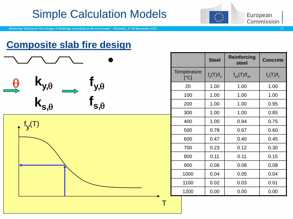
Simple Calculation Models
Composite slab fire design
T
fy(T)
Steel Reinforcing steel Concrete
Temperature [°C] fy(T)/fy fsy(T)/fsy fc(T)/fc
20 1.00 1.00 1.00
100 1.00 1.00 1.00
200 1.00 1.00 0.95
300 1.00 1.00 0.85
400 1.00 0.94 0.75
500 0.78 0.67 0.60
600 0.47 0.40 0.45
700 0.23 0.12 0.30
800 0.11 0.11 0.15
900 0.06 0.08 0.08
1000 0.04 0.05 0.04
1100 0.02 0.03 0.01
1200 0.00 0.00 0.00
θ ky,θ fy,θ
ks,θ fs,θ
Workshop ‘Structural Fire Design of Buildings according to the Eurocodes’ – Brussels, 27-28 November 2012 38
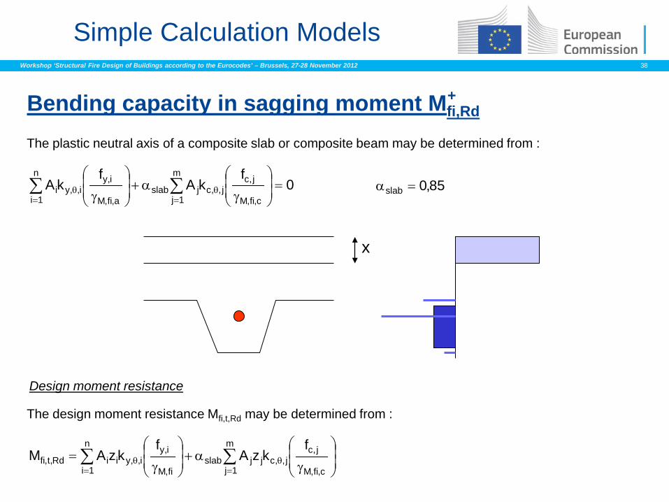
Simple Calculation Models
Bending capacity in sagging moment Mfi,Rd
x
Design moment resistance
The plastic neutral axis of a composite slab or composite beam may be determined from :
The design moment resistance Mfi,t,Rd may be determined from :
∑∑=
θ=
θ =
γα+
γ
m
1j c,fi,M
j,cj,,cjslab
n
1i a,fi,M
i,yi,,yi 0
fkA
fkA 85,0slab =α
∑∑=
θ=
θ
γα+
γ=
m
1j c,fi,M
j,cj,,cjjslab
n
1i fi,M
i,yi,,yiiRd,t,fi
fkzA
fkzAM
+

Workshop ‘Structural Fire Design of Buildings according to the Eurocodes’ – Brussels, 27-28 November 2012 39
X
Y
I II
III
IV
(0 , YI) (XII , YI)
(XIII , YIII)
(XIV , YIV) Isotherm for θ = θlim
Simple Calculation Models
Temperature field
354
r32
2
310s
1ccLAczc
hucc
+α⋅+⋅+⋅+⋅+=θ
Xi and Yi = f(z)
343
r2s10lim
1ddLAdNdd
+Φ⋅+⋅+⋅+=θwith
and
Bending capacity in hogging moment Mfi,Rd -
z is obtained from the equation for the determination of θs, assuming that u3/h2 = 0,75 and θs = θlim
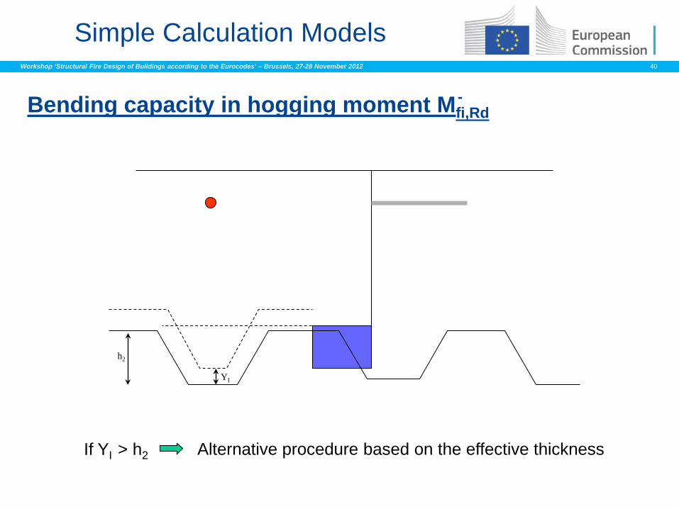
Workshop ‘Structural Fire Design of Buildings according to the Eurocodes’ – Brussels, 27-28 November 2012 40
Simple Calculation Models
h2
YI
If YI > h2 Alternative procedure based on the effective thickness
Bending capacity in hogging moment Mfi,Rd -
Workshop ‘Structural Fire Design of Buildings according to the Eurocodes’ – Brussels, 27-28 November 2012 41
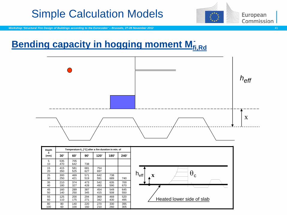
Simple Calculation Models
heff
x
heff θc
Heated lower side of slab
x
Depth X
[mm]
Temperature θc [°C] after a fire duration in min. of
30’ 60’ 90’ 120’ 180’ 240’ 5 10
535 470
705 642
738
15 20
415 350
581 525
681 627
754 697
25 30
300 250
469 421
571 519
642 591
738 689
740
35 40
210 180
374 327
473 428
542 493
635 590
700 670
45 50
160 140
289 250
387 345
454 415
549 508
645 550
55 60
125 110
200 175
294 271
369 342
469 430
520 495
80 100
80 60
140 100
220 160
270 210
330 260
395 305
Bending capacity in hogging moment Mfi,Rd -
Workshop ‘Structural Fire Design of Buildings according to the Eurocodes’ – Brussels, 27-28 November 2012 42
Simple Calculation Models
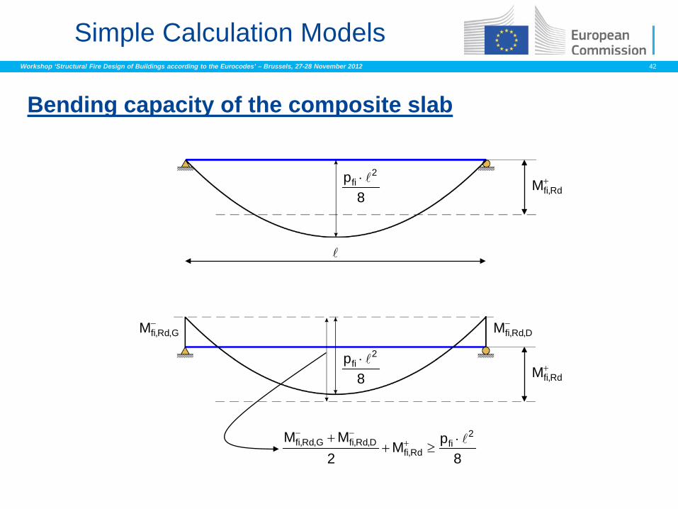
Bending capacity of the composite slab
+Rd,fiM
−D,Rd,fiM−
G,Rd,fiM
8p 2
fi ⋅
8p 2
fi ⋅ +Rd,fiM
8pM
2MM 2
fiRd,fi
D,Rd,fiG,Rd,fi ⋅≥+
+ +−−
Workshop ‘Structural Fire Design of Buildings according to the Eurocodes’ – Brussels, 27-28 November 2012 43
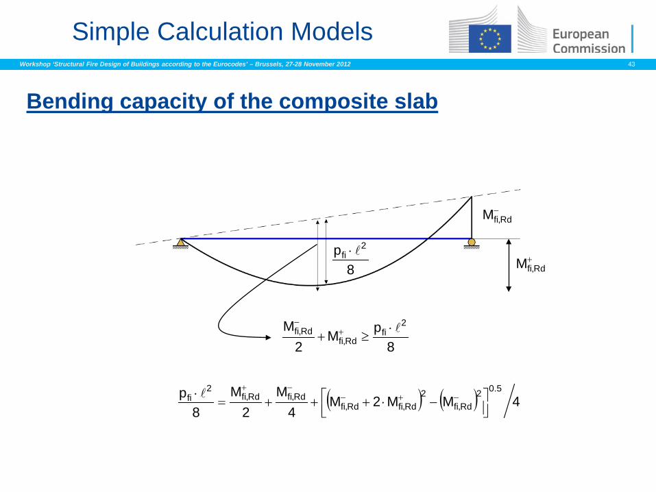
Simple Calculation Models
−Rd,fiM
8p 2
fi ⋅ +Rd,fiM
8pM
2M 2
fiRd,fi
Rd,fi ⋅≥+ +
−
( ) ( ) 4MM2M4
M2
M8
p 5.02Rd,fi
2Rd,fiRd,fi
Rd,fiRd,fi2
fi
−⋅+++=
⋅ −+−−+
Bending capacity of the composite slab
Workshop ‘Structural Fire Design of Buildings according to the Eurocodes’ – Brussels, 27-28 November 2012 44
Simple Calculation Models
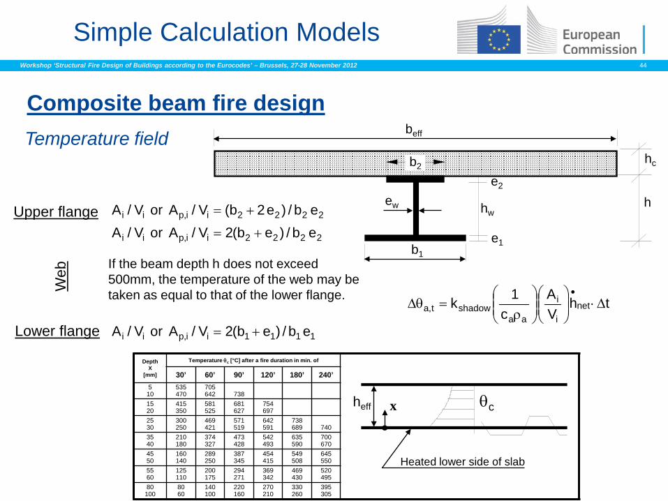
Composite beam fire design
Temperature field
b1
hw
b2
beff
e2
e1
ew h
hc
thVA
c1k net
i
i
aashadowt,a ∆⋅
ρ=θ∆
•
Upper flange
Lower flange
Web
1111ii,pii eb/)eb(2V/AorV/A +=
2222ii,pii eb/)e2b(V/AorV/A +=
2222ii,pii eb/)eb(2V/AorV/A +=
If the beam depth h does not exceed 500mm, the temperature of the web may be taken as equal to that of the lower flange.
heff θc
Heated lower side of slab
x
Depth X
[mm]
Temperature θc [°C] after a fire duration in min. of
30’ 60’ 90’ 120’ 180’ 240’ 5 10
535 470
705 642
738
15 20
415 350
581 525
681 627
754 697
25 30
300 250
469 421
571 519
642 591
738 689
740
35 40
210 180
374 327
473 428
542 493
635 590
700 670
45 50
160 140
289 250
387 345
454 415
549 508
645 550
55 60
125 110
200 175
294 271
369 342
469 430
520 495
80 100
80 60
140 100
220 160
270 210
330 260
395 305
Workshop ‘Structural Fire Design of Buildings according to the Eurocodes’ – Brussels, 27-28 November 2012 45
Simple Calculation Models
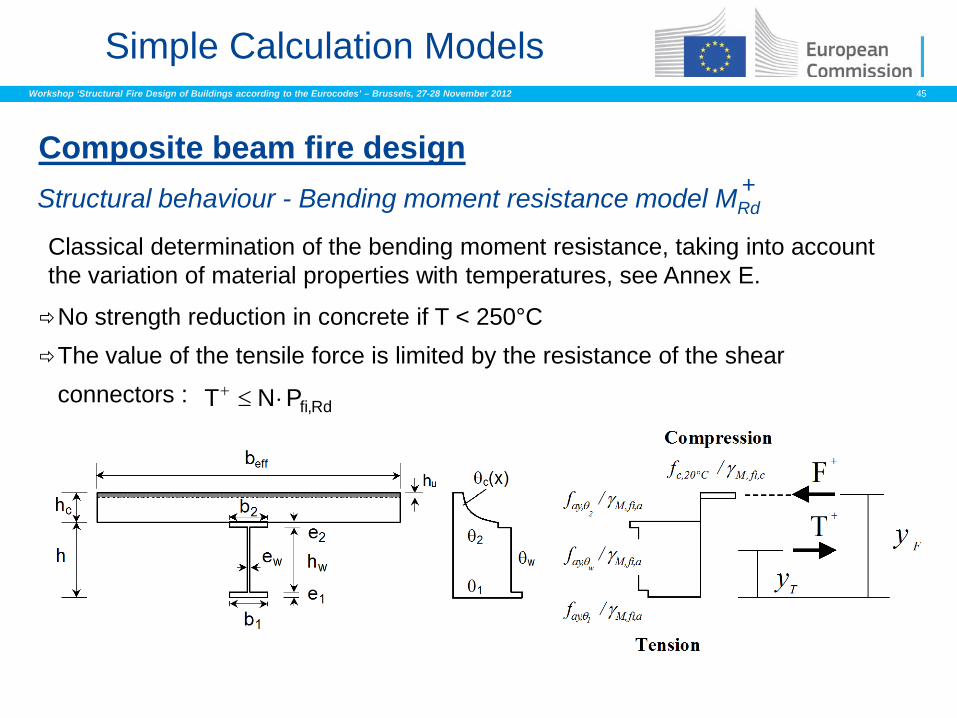
Structural behaviour - Bending moment resistance model MRd +
Classical determination of the bending moment resistance, taking into account the variation of material properties with temperatures, see Annex E.
No strength reduction in concrete if T < 250°C The value of the tensile force is limited by the resistance of the shear
connectors :
Composite beam fire design
Rd,fiPNT ⋅≤+
Workshop ‘Structural Fire Design of Buildings according to the Eurocodes’ – Brussels, 27-28 November 2012 46
Simple Calculation Models
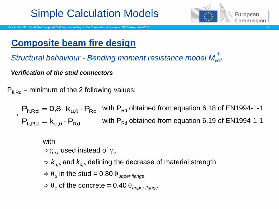
Structural behaviour - Bending moment resistance model MRd +
Composite beam fire design
Pfi,Rd = minimum of the 2 following values:
with
Verification of the stud connectors
γm,fi used instead of γν
ku,θ and kc,θ defining the decrease of material strength
θu in the stud = 0.80 θupper flange
θc of the concrete = 0.40 θupper flange
with PRd obtained from equation 6.18 of EN1994-1-1
with PRd obtained from equation 6.19 of EN1994-1-1 Rd,uRd,fi Pk8,0P ⋅⋅= θ
Rd,cRd,fi PkP ⋅= θ
Workshop ‘Structural Fire Design of Buildings according to the Eurocodes’ – Brussels, 27-28 November 2012 47
Simple Calculation Models
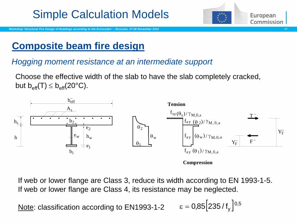
Composite beam fire design
Hogging moment resistance at an intermediate support Choose the effective width of the slab to have the slab completely cracked, but beff(T) ≤ beff(20°C).
Tension
Compression
beff−
As
hc
h
b2
hw
e2
e1
ew
b1
θ2
θwθ1
fs s M fiy , ,s( ) /θ γfa 2 M fiy , ,a( ) /θ γ
fa w M fiy , ,a( ) /θ γ
fa M fiy , ,a( ) /θ γ1
YF−
YT−
T −
F −
If web or lower flange are Class 3, reduce its width according to EN 1993-1-5. If web or lower flange are Class 4, its resistance may be neglected. Note: classification according to EN1993-1-2 [ ] 5,0
yf/23585,0=ε
Workshop ‘Structural Fire Design of Buildings according to the Eurocodes’ – Brussels, 27-28 November 2012 48
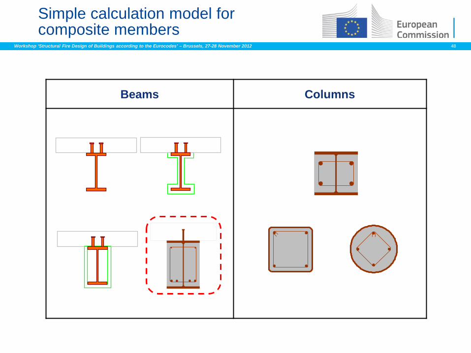
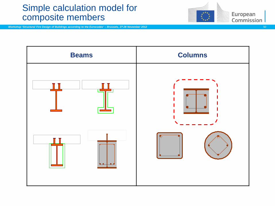
Simple calculation model for composite members
Beams Columns
Workshop ‘Structural Fire Design of Buildings according to the Eurocodes’ – Brussels, 27-28 November 2012 49
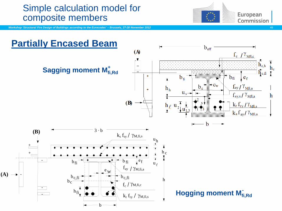
Simple calculation model for composite members
Partially Encased Beam
Sagging moment Mfi,Rd +
3 · b
b
h
b fi b
b c
h c
u e f
u h
b c,fi b c,fi
h fi
e w (A)
(B)
kr fry γM,fi,s
fc γM,fi,c
fay γM,fi,a
ks fsy γM,fi,s
+
fi
+
-
-
- -
Hogging moment Mfi,Rd -
Workshop ‘Structural Fire Design of Buildings according to the Eurocodes’ – Brussels, 27-28 November 2012 50
Simple calculation model for composite members
Beams Columns
Workshop ‘Structural Fire Design of Buildings according to the Eurocodes’ – Brussels, 27-28 November 2012 51
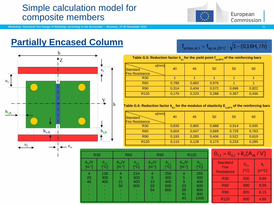
)V/A(k mtt,0t,f +θ=θ
Simple calculation model for composite members
Partially Encased Column
Z
Y h
ef
b
ew u2
u1
bc,fi
bc,fi hw,fi
)h/H16,0(1ff tC20,w,ayt,wmax,a −⋅= °
Table G.5: Reduction factor ky,t
for the yield point fsy,20°C
of the reinforcing bars
u[mm] Standard Fire Resistance
40 45 50 55 60
R30 1 1 1 1 1 R60 0,789 0,883 0,976 1 1 R90 0,314 0,434 0,572 0,696 0,822 R120 0,170 0,223 0,288 0,367 0,436
Table G.6: Reduction factor kE,t
for the modulus of elasticity Es,20°C of the reinforcing bars
u[mm] Standard Fire Resistance
40 45 50 55 60
R30 0,830 0,865 0,888 0,914 0,935 R60 0,604 0,647 0,689 0,729 0,763 R90 0,193 0,283 0,406 0,522 0,619 R120 0,110 0,128 0,173 0,233 0,285
R30 R60 R90 R120
Am/V [m-1]
θc,t [°C]
Am/V [m-1]
θc,t [°C]
Am/V [m-1]
θc,t [°C]
Am/V [m-1]
θc,t [°C]
4 23 46 - - - -
136 300 400
- - - -
4 9 21 50 - - -
214 300 400 600
- - -
4 6 13 33 54 - -
256 300 400 600 800
- -
4 5 9 23 38 41 43
265 300 400 600 800 900 1000
Standard Fire
Resistance
θ0,t
[°C]
kt
[m°C]
R30 550 9,65
R60 680 9,55
R90 805 6,15
R120 900 4,65
Workshop ‘Structural Fire Design of Buildings according to the Eurocodes’ – Brussels, 27-28 November 2012 52
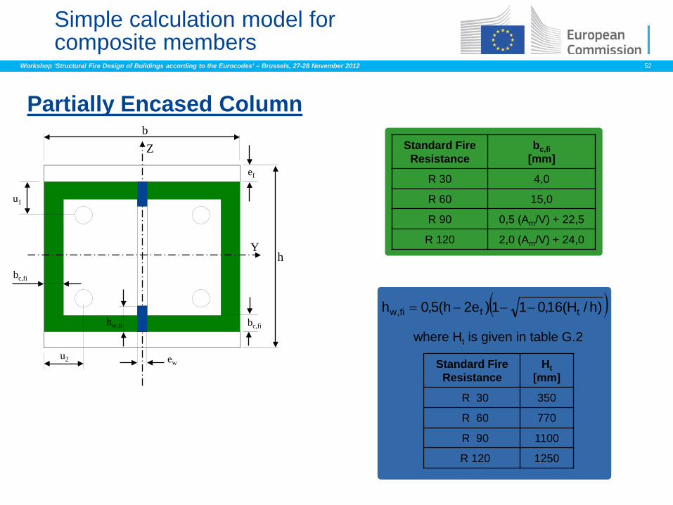
Simple calculation model for composite members
Partially Encased Column
( ))h/H(16,011)e2h(5,0h tffi,w −−−=
where Ht is given in table G.2
Standard Fire Resistance
Ht [mm]
R 30 350
R 60 770
R 90 1100
R 120 1250
Z
Y h
ef
b
ew u2
u1
bc,fi
bc,fi hw,fi
Standard Fire Resistance
bc,fi [mm]
R 30 4,0
R 60 15,0
R 90 0,5 (Am/V) + 22,5
R 120 2,0 (Am/V) + 24,0
Workshop ‘Structural Fire Design of Buildings according to the Eurocodes’ – Brussels, 27-28 November 2012 53
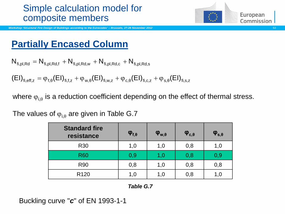
Simple calculation model for composite members
Partially Encased Column
Buckling curve "c" of EN 1993-1-1
fi,s,zs,θfi,c,zc,θfi,w,zw,θfi,f,zf,θfi,eff,z (EI)(EI)(EI)(EI)(EI) ϕ+ϕ+ϕ+ϕ=
fi,pl,Rd,sfi,pl,Rd,cfi,pl,Rd,wfi,pl,Rd,ffi,pl,Rd NNNNN +++=
where ϕi,θ is a reduction coefficient depending on the effect of thermal stress. The values of ϕi,θ are given in Table G.7
Standard fire resistance φf,θ φw,θ φc,θ φs,θ
R30 1,0 1,0 0,8 1,0
R60 0,9 1,0 0,8 0,9
R90 0,8 1,0 0,8 0,8
R120 1,0 1,0 0,8 1,0
Table G.7
Workshop ‘Structural Fire Design of Buildings according to the Eurocodes’ – Brussels, 27-28 November 2012 54
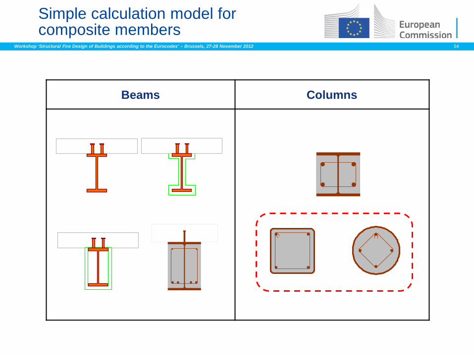
Simple calculation model for composite members
Beams Columns


![Pre-Engineered Buildings Structural Steel Buildings ...€¦ · Pre-Engineered Buildings Structural Steel Buildings LEADERS IN THE STEEL BUILDINGS INDUSTRY mKÁúeTsk_ vis½y]sSahkmµ](https://img.pdfslide.net/doc/110x75/5f069e707e708231d418e449/pre-engineered-buildings-structural-steel-buildings-pre-engineered-buildings.jpg)