Embed Size (px)
Citation preview

W P C A
Worldwide Pollution
Control Association
WPCA-Duke Energy Is Your Precipitator Ready for MATS?
Aug. 28, 2012 – Plainfield
Sept. 11, 2012 - Charlotte
Visit our website at www.wpca.info
All presentations posted on this website are copyrighted by the Worldwide Pollution
Control Association (WPCA). Any unauthorized downloading, attempts to modify or to
incorporate into other presentations, link to other websites, or to obtain copies for any
other purposes than the training of attendees to WPCA Conferences is expressly
prohibited, unless approved in writing by the WPCA or the original presenter. The
WPCA does not assume any liability for the accuracy or contents of any materials
contained in this library which were presented and/or created by persons who were
not employees of the WPCA.
IMPROVING ESP PERFORMANCE WITHIMPROVING ESP PERFORMANCE WITH VOLTAGE AND RAPPER CONTROL SETTINGS
DIAGNOSING PROBLEMS USING VOLTAGE CONTROL METERSDIAGNOSING PROBLEMS USING VOLTAGE CONTROL METERS
PRESENTED AT WPCA/DUKE ENERGY SEMINARIS YOUR PRECIPITATOR READY FOR MATS?
AUG. 28, 2012PLAINFIELD, INSEPT. 11, 2012
CHARLOTTE, NC
CHRISTOPHER ROGLIERICHRISTOPHER ROGLIERIKC COTTRELL INC.
LODGE COTTRELL INC.
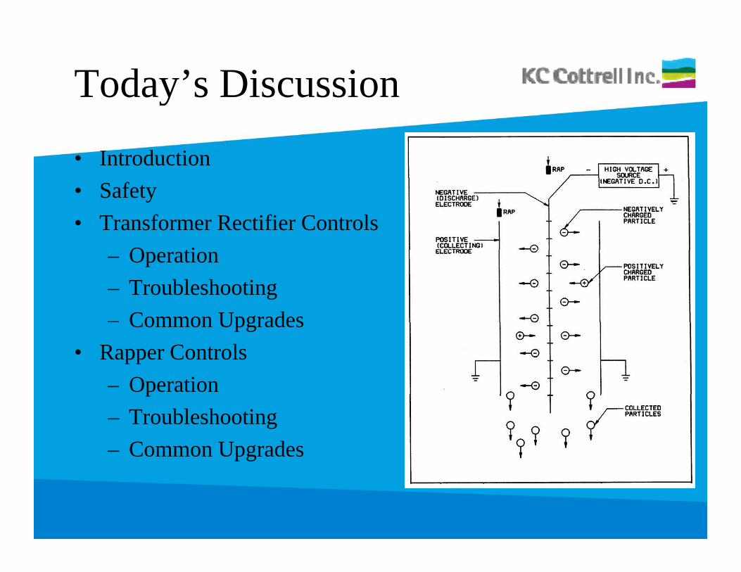
Today’s Discussiony
• Introduction• Safety• Transformer Rectifier Controls
O ti– Operation– Troubleshooting– Common UpgradesCommon Upgrades
• Rapper Controls– Operationp– Troubleshooting– Common Upgrades
Introduction
• Understanding controls operationUnderstanding controls operation
• Determine when a problem exists• Determine when a problem exists
• Improving precipitator performance by optimizing• Improving precipitator performance by optimizing control settings
• General Troubleshooting practices
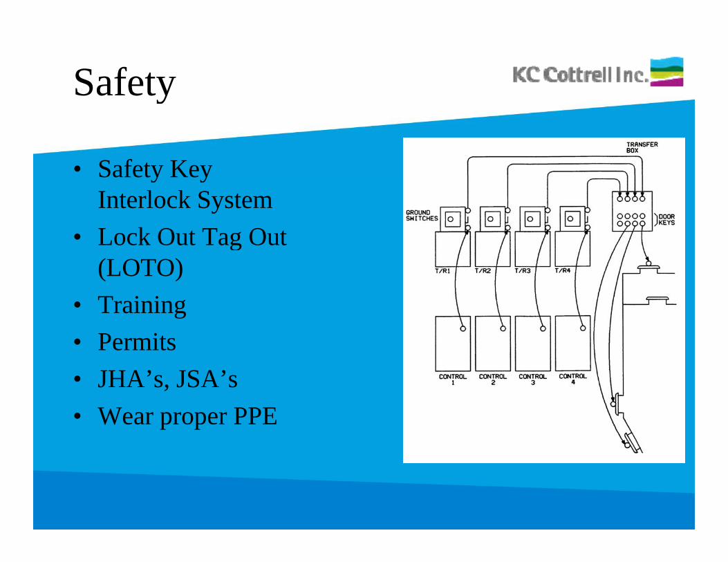
Safetyy
• Safety KeySafety KeyInterlock System
• Lock Out Tag Outg(LOTO)
• Trainingg• Permits• JHA’s, JSA’sJ s, JS s• Wear proper PPE
Safety (cont’d)y
• Most utilities now requireMost utilities now require flash protection at voltages >120VAC
• Troubleshooting should be gperformed by a qualified electrician or properly trained technician.
• Follow plant guidelines for troubleshooting energized equipment, LOTO and key interlock system.
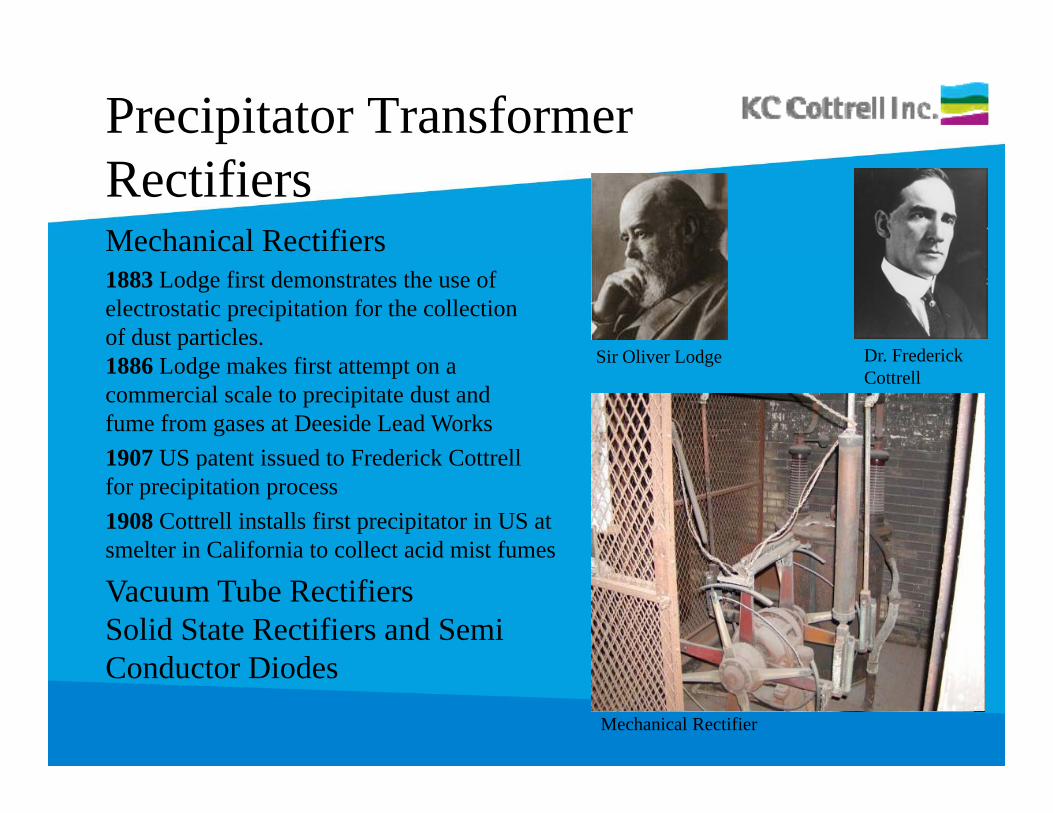
Precipitator Transformer RectifiersMechanical Rectifiers1883 Lodge first demonstrates the use of electrostatic precipitation for the collection of dust particles.
Dr FrederickSir Oliver Lodge1886 Lodge makes first attempt on a commercial scale to precipitate dust and fume from gases at Deeside Lead Works1907 US patent issued to Frederick Cottrell
Dr. Frederick Cottrell
Sir Oliver Lodge
1907 US patent issued to Frederick Cottrell for precipitation process1908 Cottrell installs first precipitator in US atsmelter in California to collect acid mist fumes
Vacuum Tube RectifiersSolid State Rectifiers and SemiC d t Di dConductor Diodes
Mechanical Rectifier
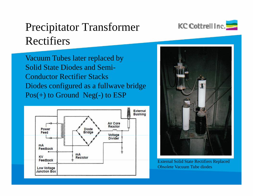
Precipitator Transformer RectifiersVacuum Tubes later replaced byp ySolid State Diodes and Semi-Conductor Rectifier Stacks Diodes configured as a fullwave bridgeDiodes configured as a fullwave bridgePos(+) to Ground Neg(-) to ESP
E l S lid S R ifi R l dExternal Solid State Rectifiers Replaced Obsolete Vacuum Tube diodes
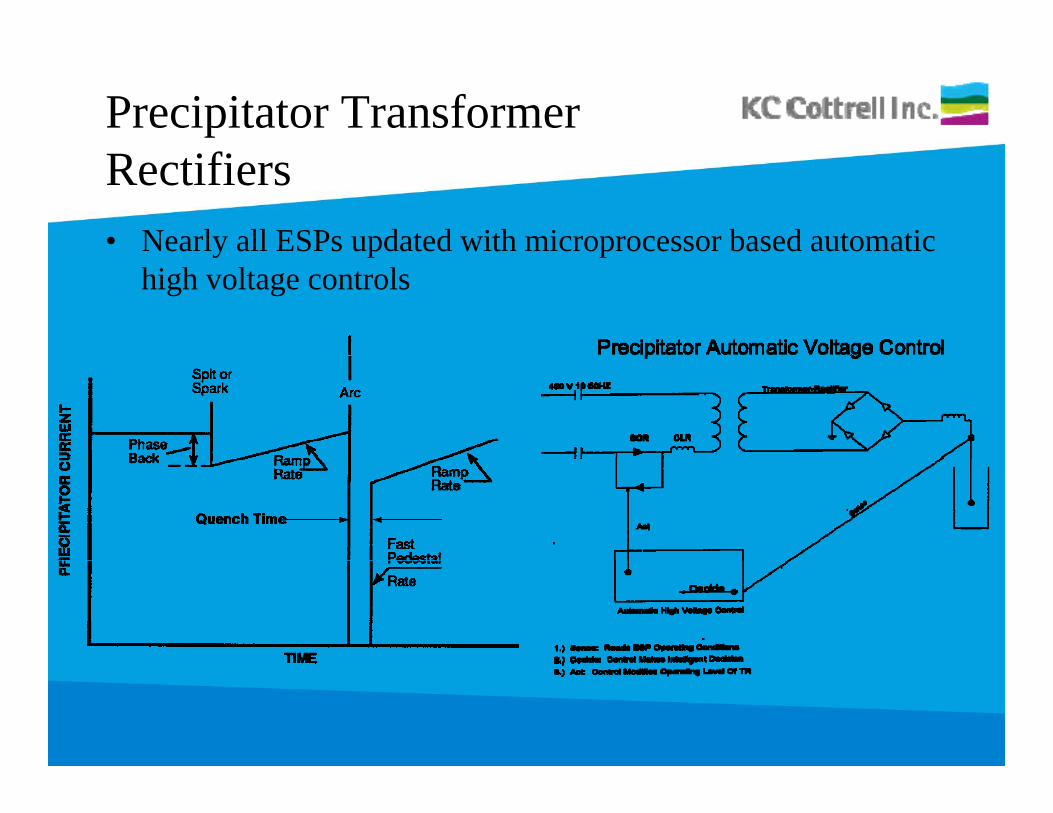
Precipitator Transformer Rectifiers• Nearly all ESPs updated with microprocessor based automatic y p p
high voltage controls
Control Operation
• Maintain highest power levels in electrostatic precipitator tog p p pmaximize charging strength and efficiency
• Modify/adjust power levels for upset conditions, sparks/arcs• Ramps power to operator programmed limits/set points of
voltage and current, or• Reduces power if an upset condition (spark) occurs• Reduces power if an upset condition (spark) occurs• Continuously ramps to limits/set points (especially after a
spark) to maintain maximum precipitation rate• Most problems are identified by an alarm• All alarms should be proven and addressed
Primary Voltage Vpy g p
• Primary Voltage -RMS volts measured after SCR andPrimary Voltage RMS volts measured after SCR and CLR used for metering and undervoltage trip alarm– SCR and snubber circuit varies conduction angle g
(voltage regulator) driven by AVC microprocessor– Control relies on feedback of Vp , Ip and Is (typ.)p , p s ( yp )– Voltage drop over CLR and field cable– Line Voltage typ. (480VAC)e Vo ge yp. ( V C)– Control Voltage (120VAC)– Primary Voltage Vp (actual T-R input voltage)Primary Voltage Vp (actual T R input voltage)• Use TRMS meter to check or calibrate
Primary Voltage Vpy g p
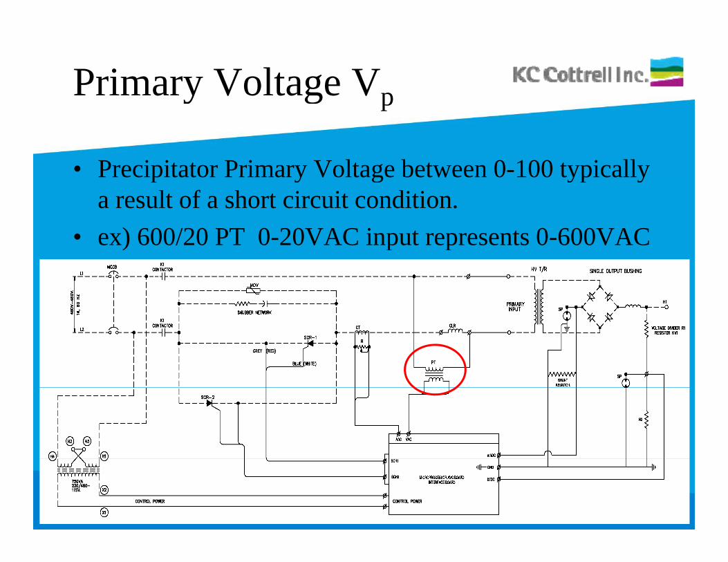
• Precipitator Primary Voltage between 0-100 typicallyPrecipitator Primary Voltage between 0 100 typically a result of a short circuit condition.
• ex) 600/20 PT 0-20VAC input represents 0-600VAC) p p
Primary Voltage Vpy g p
0 Volts?0 Volts?– Control will trip on Undervoltage if minimum
current limit is not met.– Primary voltage signal is typ. reduced prior to
AVC board or analog volt-meter using step-down g g ptransformer.
– Locate CLR (typ. inside control cabinet, external, or inside T-R oil tank)
– Primary volt signal wiring typically located at Transformer Tap (LV junction box) or at CLR

Primary Voltage Vpy g p
0 Volts? (cont’d)0 Volts? (cont d)– Measure actual T-R volts after CLR and check
ratio.– Check fuses (typ. in series with CT primary,
located in Control Cabinet, TR LV J-box or CLR ,enclosure
– Check for proper voltages at PT primary and secondary
Primary Current Ipy p
• Primary Current -RMS amps measured on L1 or L2Primary Current RMS amps measured on L1 or L2 inline with T-R using Current Transformer (CT). Used to drive analog meters
• Feedback allows control to limit primary current.• Converted to voltage signal by adding a shunt (load) g g y g ( )
resistor. Shunt resistor value determined by control OEM (set feedback scale to primary current nameplate rating of Transformer)
• Use TRMS clamp ammeter to check or calibrate
Primary Current Ipy p
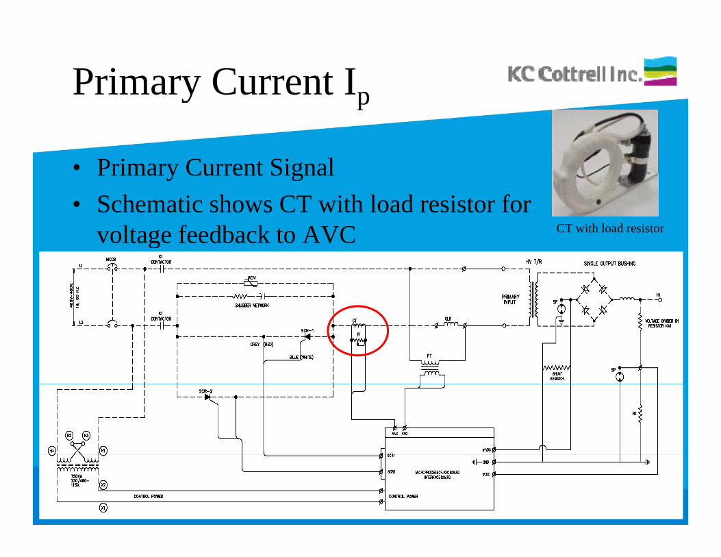
• Primary Current SignalPrimary Current Signal• Schematic shows CT with load resistor for
voltage feedback to AVC CT with load resistorg
Primary Current Ipy p
0 Amps?0 Amps?– Open Circuit?– Always verify with External TRMS Clamp meterAlways verify with External TRMS Clamp meter– Check connections
If applicable check CT load resistor (disconnect– If applicable, check CT load resistor (disconnect one end)

Primary Current Ipy p
Overcurrent Trip alarmOvercurrent Trip alarm– SCR1 or SCR2 short or misfiring– Remove and tape leads energize controlRemove and tape leads, energize control– When disconnected, Vp and Ip should be 0
Otherwise one or both SCRs are shorted or leaking– Otherwise one or both SCRs are shorted or leaking– Confirm SCR gate leads connected properly and
not switchednot switched– Replace control board
Primary Current Ipy p
Breaker TripBreaker Trip– SCR1 or SCR2 short or misfiring– Short between SCR and breakerShort between SCR and breaker– Light bulbs can be connected across outputs to
check for shortcheck for short– Control board firing circuit– Replace Breaker– Replace Breaker
Secondary Voltage (Vs)y g s
– Precipitator secondary kV typ. not a required input p y yp q pto operate HV controls (reference only)
– Older installations used divider after ACR to create current source to drive meters for display. (50MΩcreates 0-1mA current source scale representing 0-50kV)50kV)
– Most installations use additional signal resistors to t lt di id i it f i t t thcreate a voltage divider circuit for input to the
microprocessor controlMean voltage is measured by a resistance type– Mean voltage is measured by a resistance type voltage divider circuit.
Secondary Voltage (Vs)y g s
– kV divider circuit scales down T-R operatingkV divider circuit scales down T R operating voltage for input to microprocessor control
– Analog meter can be used in parallel with signal to g p gmicroprocessor.
– Voltage divider typically installed inside T-R oil g yp ytank (newer installations.)
– On older installations the divider is typ. retro-fitted inside the ground sw. enclosure or pipe & guard.
– Surge protector prevents lethal voltage outside of T-R junction box or ground switch enclosure.
Voltage Dividersg
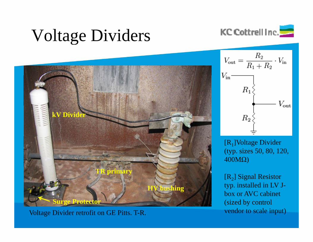
kV Divider
[R1]Voltage Divider (typ. sizes 50, 80, 120, 400MΩ)
[R2] Signal Resistor typ. installed in LV J-box or AVC cabinet
HV bushing
TR primary
Voltage Divider retrofit on GE Pitts. T-R.(sized by control vendor to scale input)
Surge Protector
Secondary Voltage Vsy g
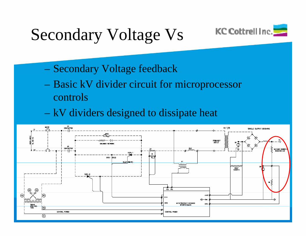
– Secondary Voltage feedbacky g– Basic kV divider circuit for microprocessor
controls– kV dividers designed to dissipate heat
Secondary Voltagey g
0 kV? – Determine kV divider and sec. signal resistor values (T-R
nameplate, schematic, or inspect voltage divider)Ch k t l d l f i t l– Check control vendor manual for input scale
– Voltage divider can be Meg-Ohm tested to confirm value (follow LOTO and key interlock procedure)( O O y p )
– Secondary resistor is sometimes adjustable (slide resistor) this value can be checked when disconnected from the i icircuit.
– Meg-Ohm field cableCheck surge protectors (Meg ohm check)– Check surge protectors (Meg-ohm check)
Secondary Voltagey g
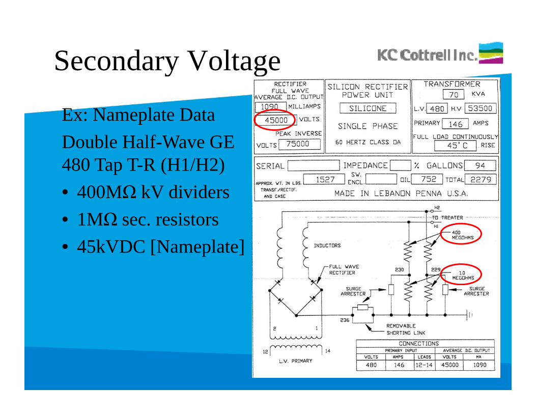
Ex: Nameplate DataDouble Half-Wave GE480 Tap T-R (H1/H2)• 400MΩ kV dividers• 1MΩ sec. resistors• 45kVDC [Nameplate]
Secondary Voltage (con’t)y g
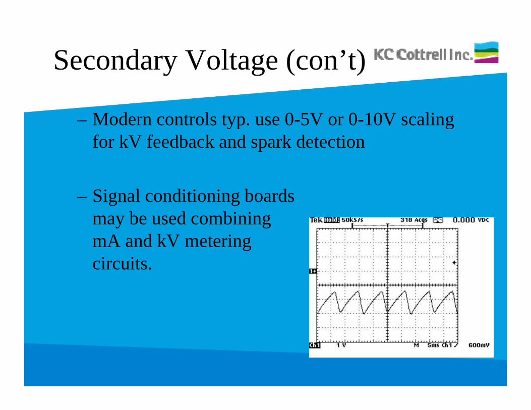
– Modern controls typ. use 0-5V or 0-10V scaling yp gfor kV feedback and spark detection
– Signal conditioning boards may be used combining mA and kV metering circuits.
Secondary Currenty
• Shunt resistor used to scale secondary mA signal.Shunt resistor used to scale secondary mA signal.• Precipitator load current passes through resistor
(connected between ground and low side of rectifier ( gbridge)
• Shunt resistor provides feedback volt signal to p gmicroprocessor based on T-R secondary current rating.
• Surge protector prevents lethal voltage outside of T-R junction box or ground switch enclosure.
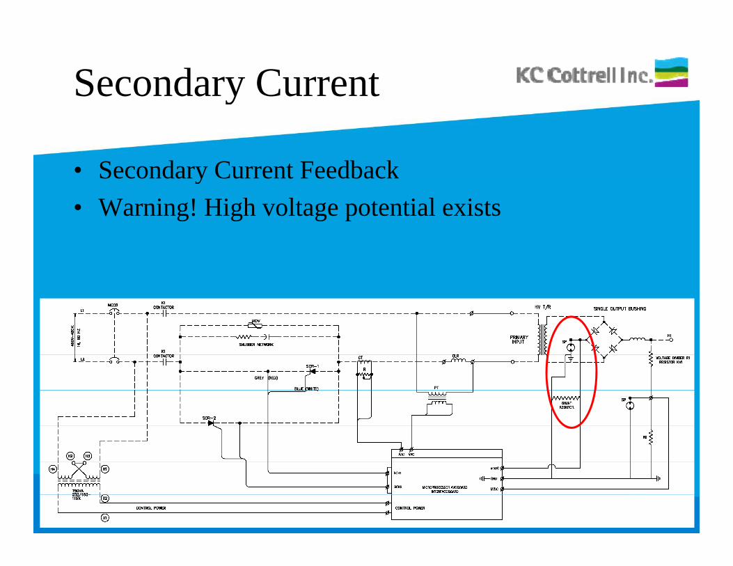
Secondary Currenty
• Secondary Current FeedbackSecondary Current Feedback• Warning! High voltage potential exists
Secondary Currenty
• 0 mA?0 mA?– If primary and secondary amps are 0, try short circuit
testing TR• Current present => Open Circuit inside ESP• 0 Current => Open circuit between control and TR
– Meg-Ohm field cableMeg-Ohm field cable– Check surge protectors (Meg-ohm check)– Meg-Ohm TR primary and secondaryg p y y
• Open primary => Repair TR• Open secondary => check diode stack
Normal Operation
– Precipitator voltage should be above about 30 kilovolts p gD.C. and 100 volts A.C. in all fields.
– Precipitator current (milliamps D.C. and amps A.C.) should i f i l t t tl t fi ld ll hiincrease from inlet to outlet fields, usually approaching nameplate ratings in the outlet fields.
– Precipitator sparking should diminish from inlet to outlet ec p tato spa g s ou d d s o et to out etfields, seldom exceeding about 50 sparks per minute on any one control.
Low PowerHigh Spark Rate
Low power and/or excessive sparking:
• Ash build up/ high hopper level• Tracking or cracked insulator• Rappers not working (causing excessive build up)
Precipitator kW
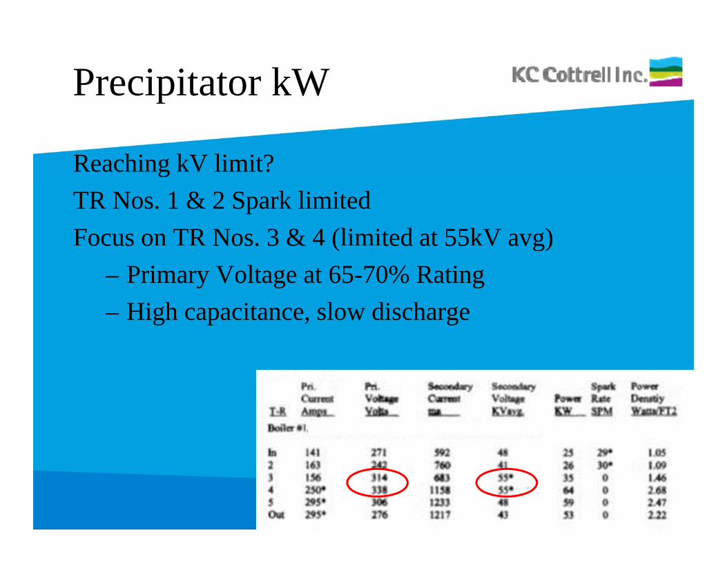
Reaching kV limit?gTR Nos. 1 & 2 Spark limitedFocus on TR Nos. 3 & 4 (limited at 55kV avg)ocus o Nos. 3 & ( ted at 55 V avg)
– Primary Voltage at 65-70% Rating– High capacitance slow dischargeHigh capacitance, slow discharge
Precipitator kW
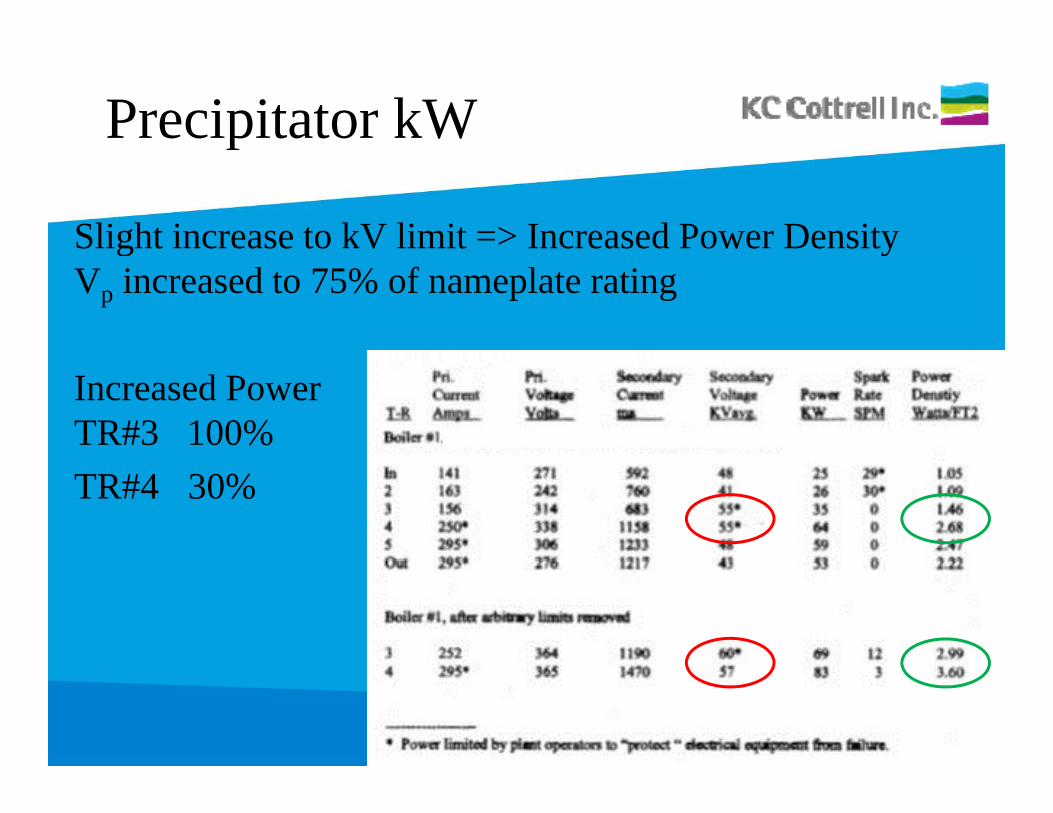
Slight increase to kV limit => Increased Power Densityg yVp increased to 75% of nameplate rating
Increased PowerTR#3 100% TR#4 30%
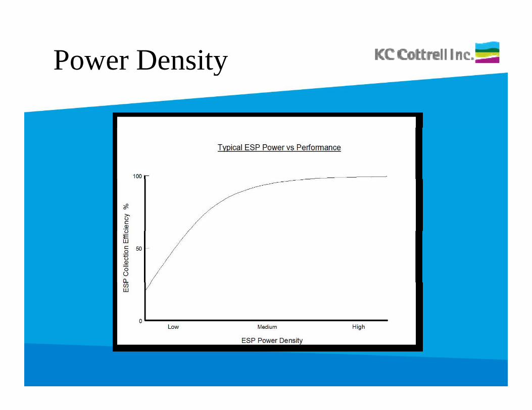
Power Densityy
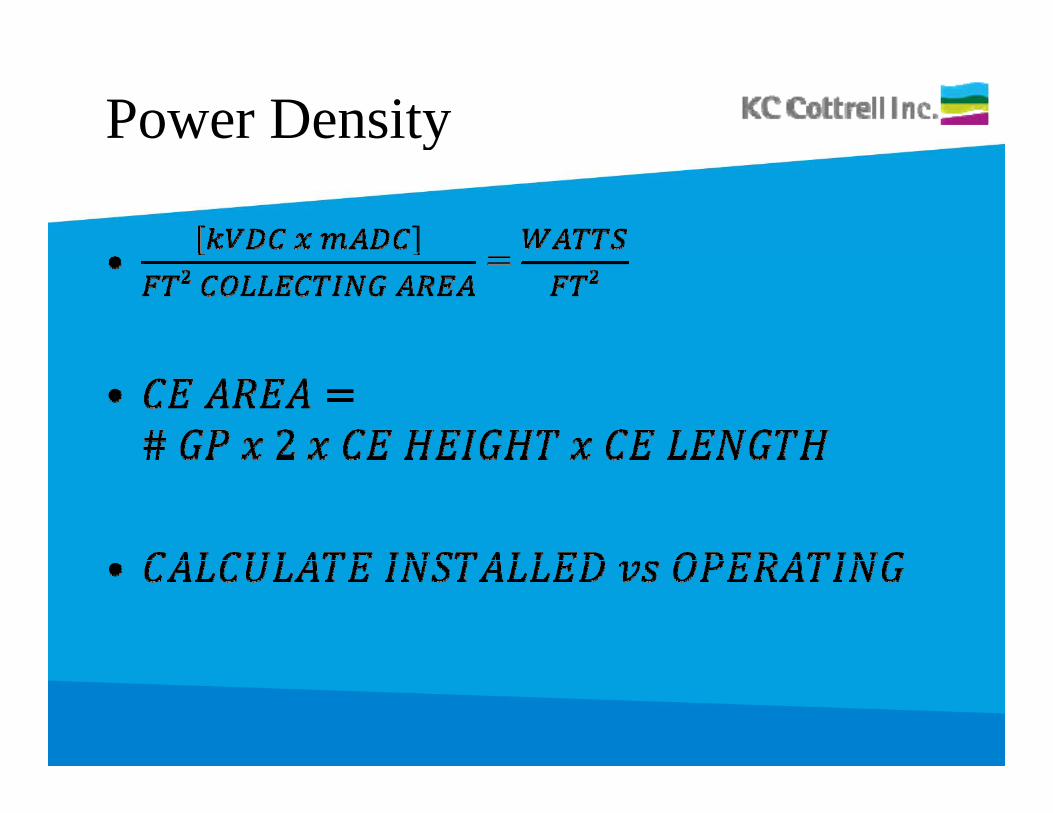
Power Densityy
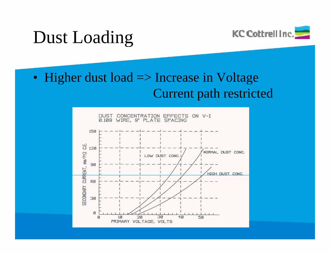
Dust Loadingg
• Higher dust load => Increase in VoltageHigher dust load > Increase in VoltageCurrent path restricted
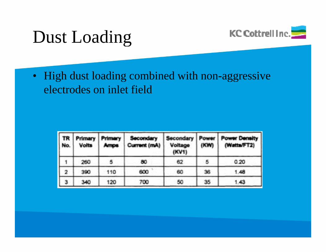
Dust Loadingg
• High dust loading combined with non-aggressiveHigh dust loading combined with non aggressive electrodes on inlet field
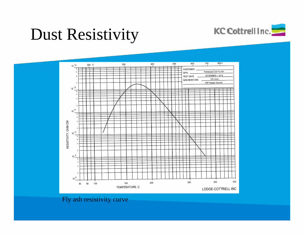
Dust Resistivityy
Fly ash resistivity curve
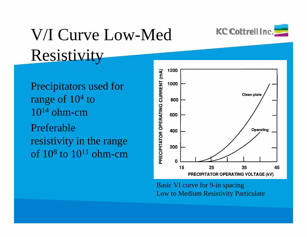
V/I Curve Low-MedResistivity
Precipitators used forrange of 104 to g1014 ohm-cmPreferableresistivity in the range of 108 to 1011 ohm-cm
Basic VI curve for 9-in spacingLow to Medium Resistivity ParticulateLow to Medium Resistivity Particulate
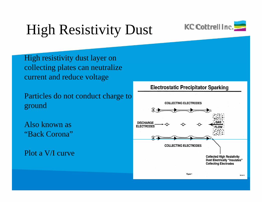
High Resistivity Dustg y
High resistivity dust layer on collecting plates can neutralize current and reduce voltage
Particles do not conduct charge to ground
Also known as “Back Corona”
Plot a V/I curve
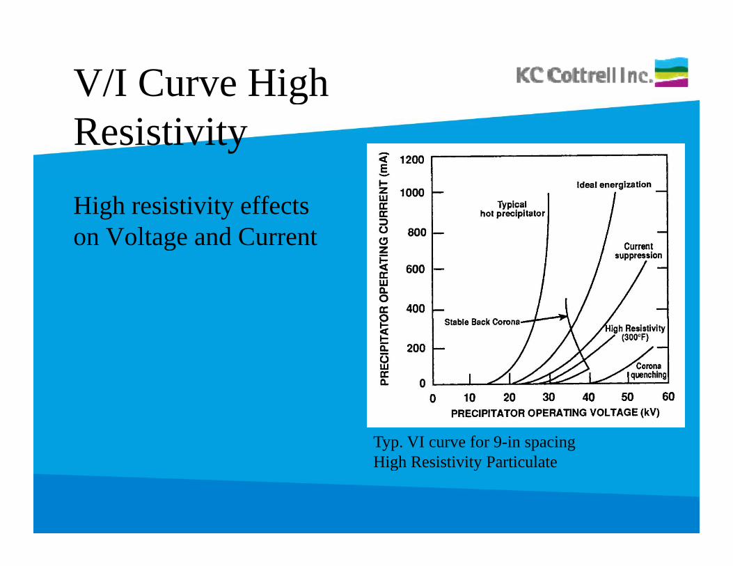
V/I Curve HighgResistivity
High resistivity effectson Voltage and Currentg
Typ. VI curve for 9-in spacingHigh Resistivity ParticulateHigh Resistivity Particulate
Back Corona
• Back corona and Intermittent Energization modesBack corona and Intermittent Energization modes have been used to find and operate at the “knee” in the V/I curve during back corona conditions and maintains the power at that point.
• Power is increased when the back corona condition is no longer present
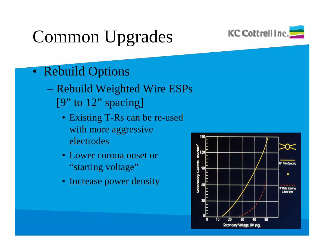
Common Upgradesg
• Rebuild Optionsp– Rebuild Weighted Wire ESPs
[9” to 12” spacing]• Existing T-Rs can be re-used
with more aggressive electrodeselectrodes
• Lower corona onset or “starting voltage”
• Increase power density
Common Upgradesg
• Rebuild Optionsp– Upgrade to more aggressive electrodes on inlet
field– Common upgrade for high inlet dust loading– Increase electrical sectionalization by adding TRs y g
or Switch Mode Power Supplies• Reduces amount of collecting area affected by spark or
di iupset condition.
Common Upgradesg
• HF SMPS (High-Freq.)( g q )– Replace existing conventional 60Hz Transformer
Rectifiers (T-Rs) with High Frequency Switch Mode Power Supplies (HF SMPS), ranging up to 25kHz
– Typically requires 3-phase to precipitator roof• MF SMPS (Mid-Freq.)
– T-Rs can be replaced with MF SMPS or – Controls can be upgraded while re-using the pg g
existing T-Rs.
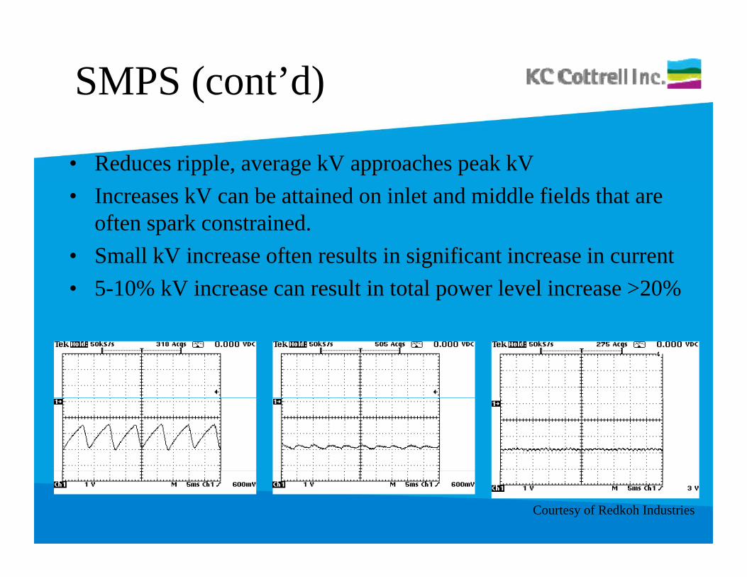
SMPS (cont’d)
• Reduces ripple, average kV approaches peak kV• Increases kV can be attained on inlet and middle fields that are
often spark constrained. S ll kV i ft lt i i ifi t i i t• Small kV increase often results in significant increase in current
• 5-10% kV increase can result in total power level increase >20%
Courtesy of Redkoh Industries
Impact on Performance
• Precipitator OEM’s are claiming sizing credits betweenPrecipitator OEM s are claiming sizing credits between 10-20%
• Average kV approaches Peak kV.g pp• Significant increase in precipitator current with small
increase in operating kV.p g• Fast recovery following spark/arc condition• Recent interest in precipitator studies and upgrades due ece e es p ec p o s ud es d upg des due
to MACT PM limit and DSI opportunities.
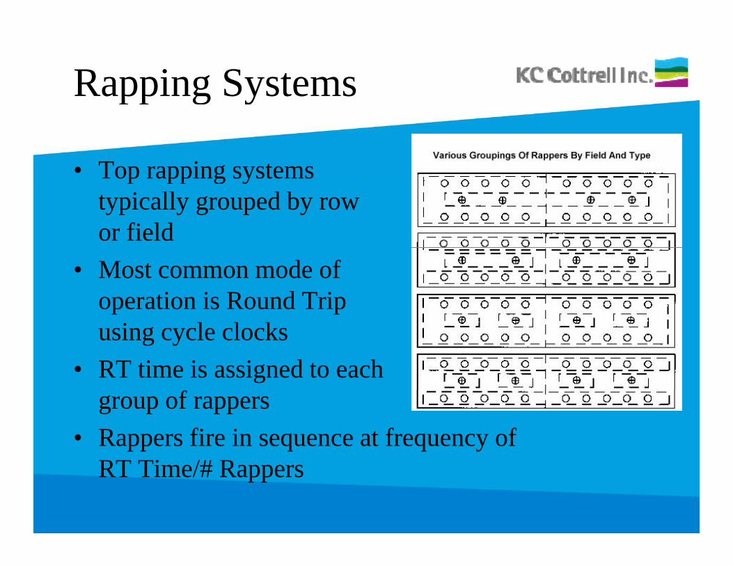
Rapping Systemsg y
• Top rapping systemsTop rapping systems typically grouped by row or field
• Most common mode ofoperation is Round Tripusing cycle clocks
• RT time is assigned to each group of rappers
• Rappers fire in sequence at frequency ofRT Ti /# RRT Time/# Rappers
Rapper Controls
• Top rapped ESPs have been updated with microprocessor p pp p pbased controls. European style rapping systems use tumbling hammer type systemsObj ti t i t i ll ti ffi i b f i• Objective to maintain collecting efficiency by forming nominal dust layer and removing with impact force to collecting surface
• Excessive ash buildup on plates reduces the inter-electrode clearances and causes high spark rates and electrical degradation of the precipitator fielddegradation of the precipitator field
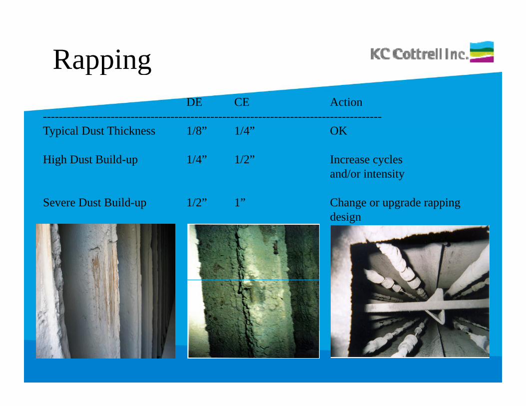
RappinggDE CE Action
-------------------------------------------------------------------------------------i l hi k / /Typical Dust Thickness 1/8” 1/4” OK
High Dust Build-up 1/4” 1/2” Increase cycles and/or intensityand/or intensity
Severe Dust Build-up 1/2” 1” Change or upgrade rapping design
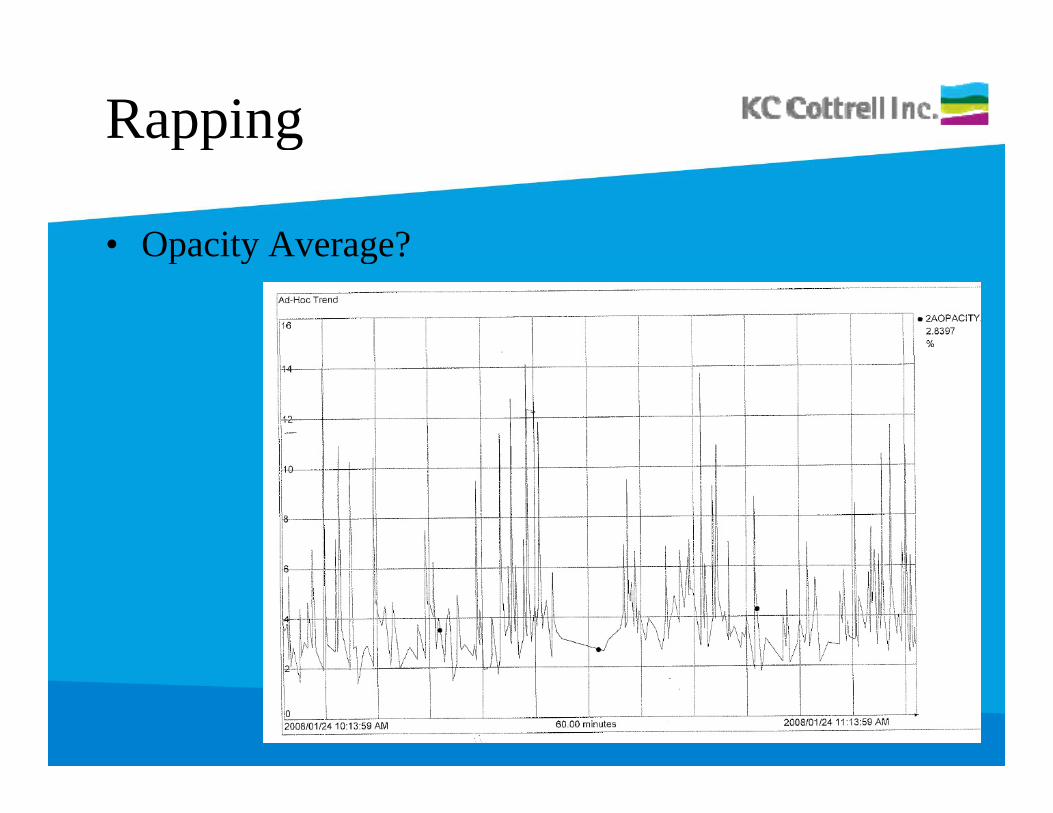
Rappingg
• Opacity Average?Opacity Average?
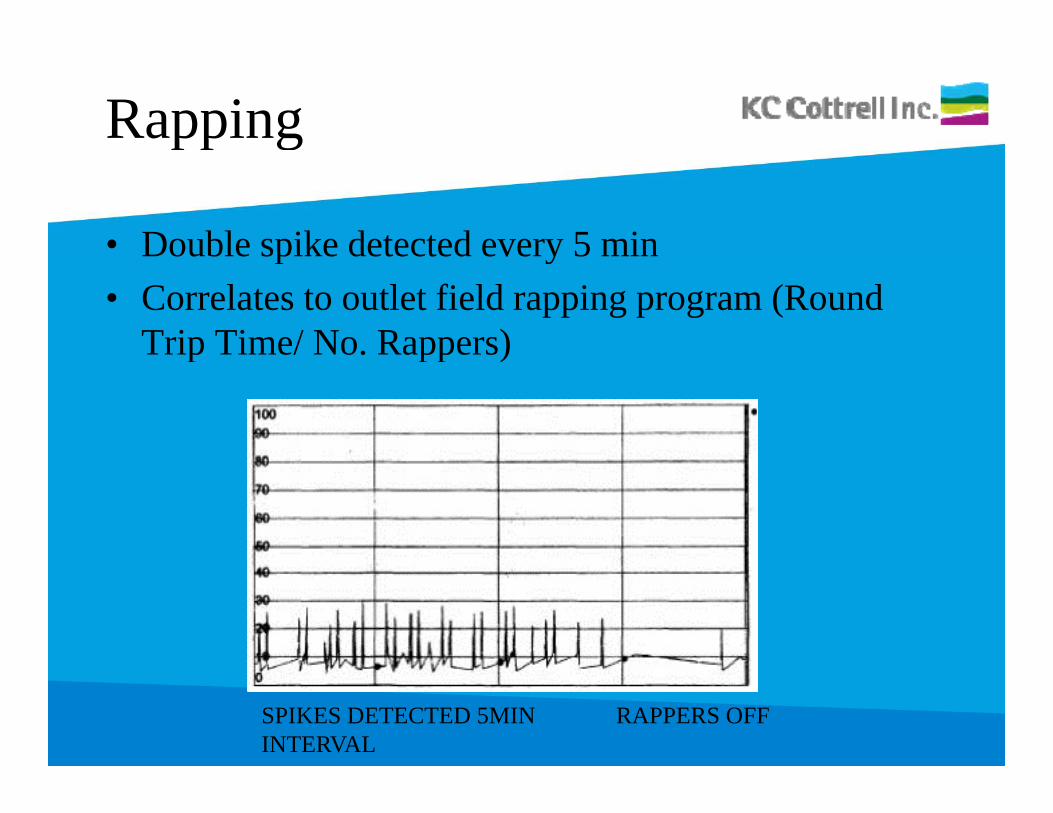
Rappingg
• Double spike detected every 5 minDouble spike detected every 5 min• Correlates to outlet field rapping program (Round
Trip Time/ No. Rappers)p pp )
RAPPERS OFFSPIKES DETECTED 5MIN INTERVAL
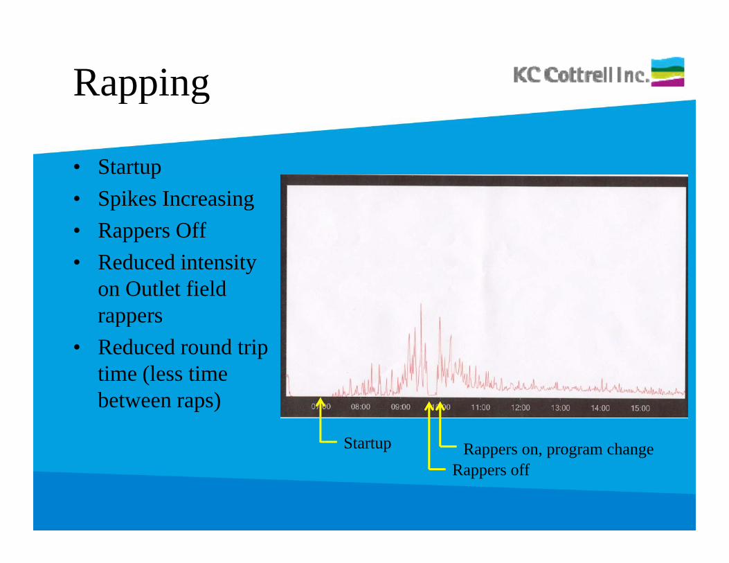
Rappingg
• Startupp• Spikes Increasing• Rappers Off• Reduced intensity
on Outlet field rappersrappers
• Reduced round triptime (less time between raps)
Startup Rappers on, program changeRappers off
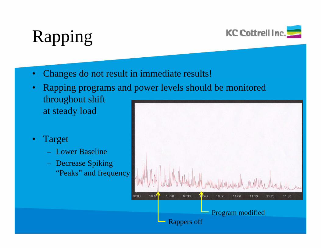
Rappingg
• Changes do not result in immediate results!g• Rapping programs and power levels should be monitored
throughout shiftt t d l dat steady load
• Target• Target– Lower Baseline– Decrease Spiking
“P k ” d f“Peaks” and frequency
Rappers offProgram modified
Rappingg
If modifications are made to the rapping program, the following pp g p g gshould be kept in mind:– Excessive rapping of collecting electrodes causes re-
entrainment of collected ash, and loss of collectionentrainment of collected ash, and loss of collection efficiency.
– Excessive rapping may cause fatigue failure of internal componentscomponents.
– Inadequate rapping causes high spark rates, low power, and loss of collection efficiency.
– Because particulate collection is concentrated at the inlet of the precipitator, rapping should be hardest and most frequent on the inlet field, and progressively less on q p g ydownstream fields.
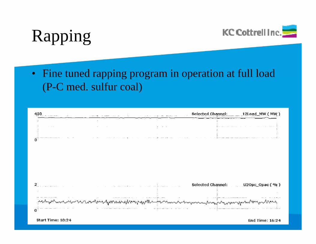
Rappingg
• Fine tuned rapping program in operation at full loadFine tuned rapping program in operation at full load (P-C med. sulfur coal)
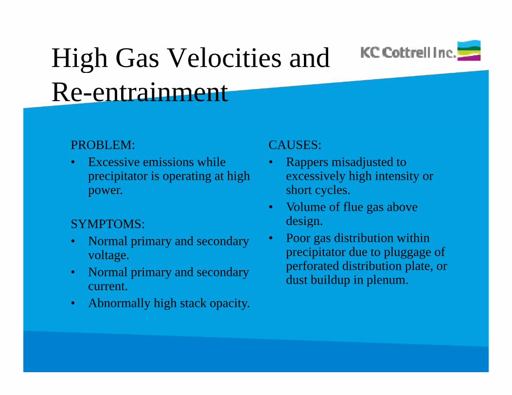
High Gas Velocities and gRe-entrainment
PROBLEM:• Excessive emissions while
i it t i ti t hi h
CAUSES:• Rappers misadjusted to
i l hi h i t itprecipitator is operating at high power.
SYMPTOMS:
excessively high intensity or short cycles.
• Volume of flue gas above designSYMPTOMS:
• Normal primary and secondary voltage.
• Normal primary and secondary
design.• Poor gas distribution within
precipitator due to pluggage of perforated distribution plate, or • Normal primary and secondary
current.• Abnormally high stack opacity.
p pdust buildup in plenum.
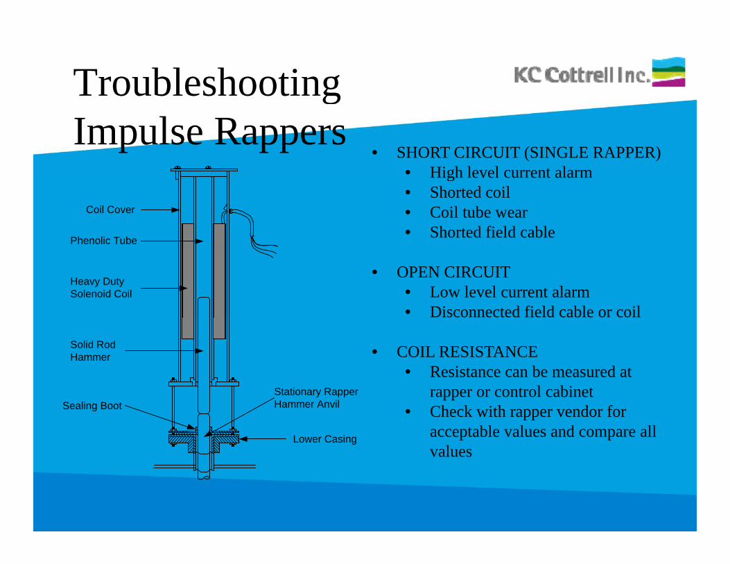
Troubleshooting gImpulse Rappers
• SHORT CIRCUIT (SINGLE RAPPER)• High level current alarm
Phenolic Tube
Coil Cover
High level current alarm• Shorted coil• Coil tube wear• Shorted field cable
Heavy DutySolenoid Coil
• OPEN CIRCUIT • Low level current alarm• Disconnected field cable or coil
Solid RodHammer
St ti R
• COIL RESISTANCE• Resistance can be measured at
t l bi tSealing Boot
Lower Casing
Stationary RapperHammer Anvil
rapper or control cabinet• Check with rapper vendor for
acceptable values and compare all values
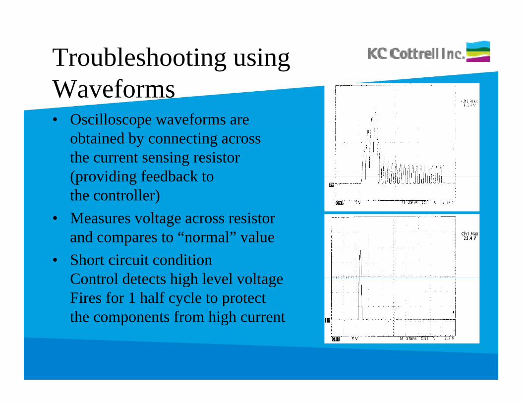
Troubleshooting using Waveforms• Oscilloscope waveforms are p
obtained by connecting across the current sensing resistor (providing feedback to(providing feedback to the controller)
• Measures voltage across resistor and compares to “normal” value
• Short circuit conditionControl detects high level voltageControl detects high level voltageFires for 1 half cycle to protect the components from high current
Common Upgradesg
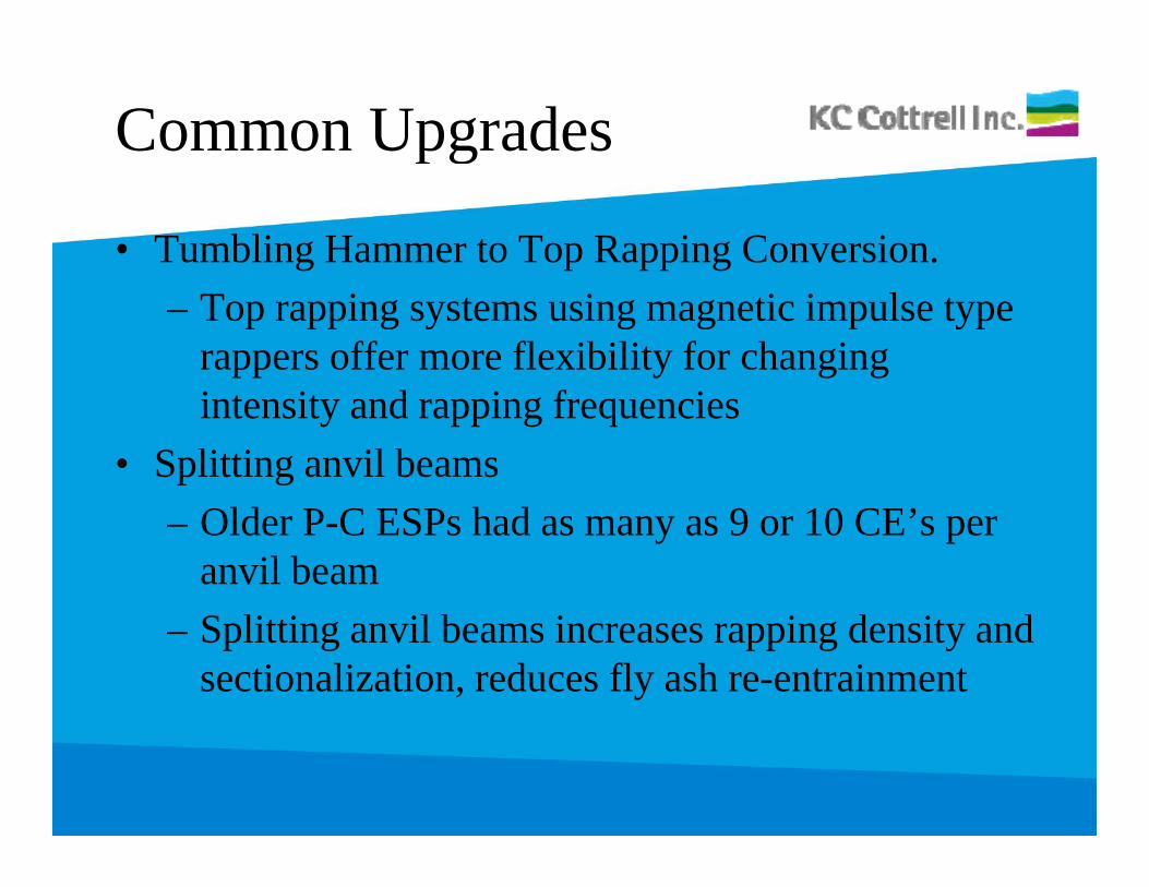
• Tumbling Hammer to Top Rapping Conversion.– Top rapping systems using magnetic impulse type
rappers offer more flexibility for changing intensity and rapping frequencies
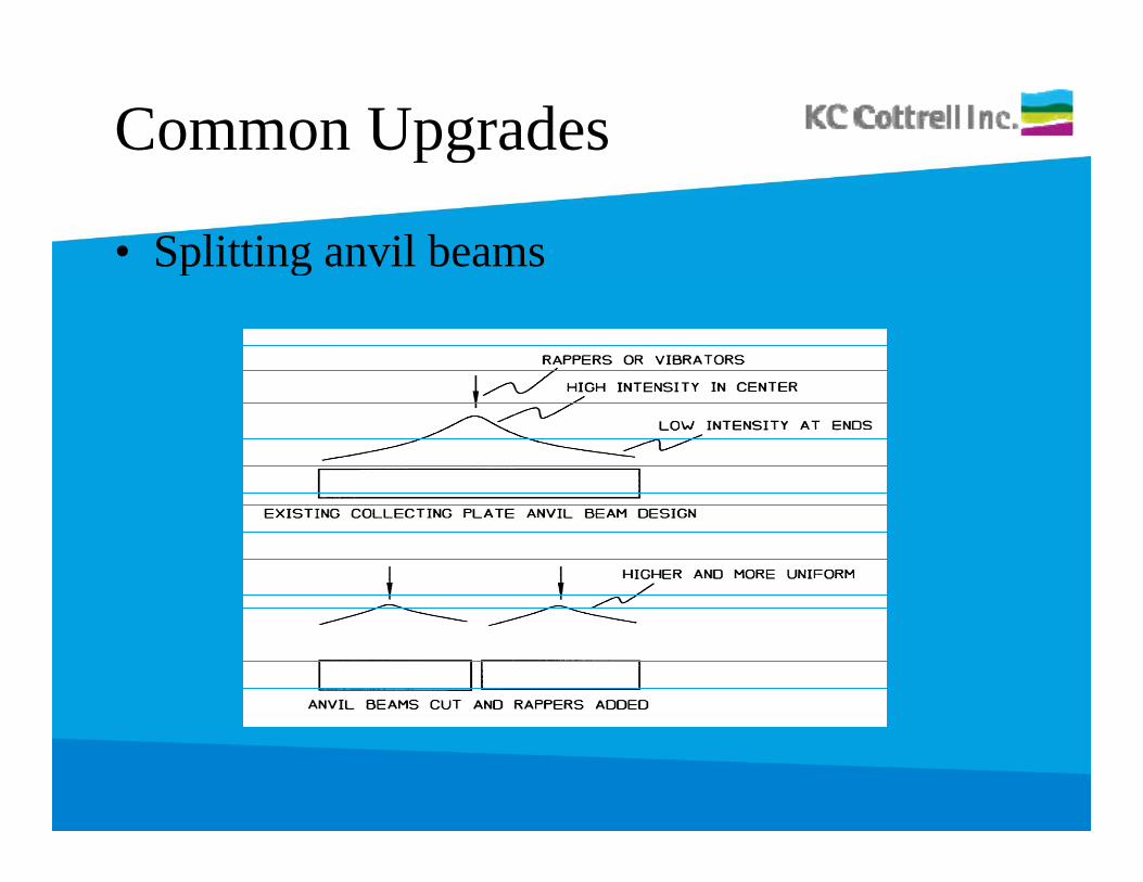
• Splitting anvil beams– Older P-C ESPs had as many as 9 or 10 CE’s per
anvil beam– Splitting anvil beams increases rapping density and
sectionalization, reduces fly ash re-entrainment
Common Upgradesg
• Splitting anvil beamsp g
Common Upgradesg
• Flue Gas Conditioning– SO3 conditioning used to improve electrical
characteristics of fly ash (improve resistivity)– NH3 conditioning used to agglomerate fly ash
particles– Flue gas conditioning used in an effort to offset the
adverse affect of low sulfur coal, particulate fines, d hi h i ti itand high resistivity.

QUESTIONS ?
THANK YOU