Embed Size (px)
Citation preview

I N D U C T O R S
NLC453232 4532 [1812 inch]*
NLC565050 5650 [2220 inch]
* Dimensions Code JIS[EIA]
July 2013
Inductors for Decoupling Circuits Wound Ferrite
NLC series

(2/15)
I N D U C T O R S
001-01 / 20130731 / inductor_commercial_decoupling_nlc_en.fm
REMINDERS FOR USING THESE PRODUCTSBefore using these products, be sure to request the delivery specifications.
SAFETY REMINDERSPlease pay sufficient attention to the warnings for safe designing when using these products.
The storage period is less than 6 months. Be sure to follow the storage conditions (Temperature: 5 to 40°C, Humidity: 10 to 75% RH or
less).
If the storage period elapses, the soldering of the terminal electrodes may deteriorate.
Do not use or store in locations where there are conditions such as gas corrosion (salt, acid, alkali, etc.).
Before soldering, be sure to preheat components.
The preheating temperature should be set so that the temperature difference between the solder temperature and chip temperature
does not exceed 150°C.
Soldering corrections after mounting should be within the range of the conditions determined in the specifications.
If overheated, a short circuit, performance deterioration, or lifespan shortening may occur.
When embedding a printed circuit board where a chip is mounted to a set, be sure that residual stress is not given to the chip due to
the overall distortion of the printed circuit board and partial distortion such as at screw tightening portions.
Self heating (temperature increase) occurs when the power is turned ON, so the tolerance should be sufficient for the set thermal
design.
Carefully lay out the coil for the circuit board design of the non-magnetic shield type.A malfunction may occur due to magnetic interference.
Use a wrist band to discharge static electricity in your body through the grounding wire.
Do not expose the products to magnets or magnetic fields.
Do not use for a purpose outside of the contents regulated in the delivery specifications.
The products listed on this catalog are intended for use in general electronic equipment (AV equipment, telecommunications
equipment, home appliances, amusement equipment, computer equipment, personal equipment, office equipment, measurement
equipment, industrial robots) under a normal operation and use condition.
The products are not designed or warranted to meet the requirements of the applications listed below, whose performance and/or
quality require a more stringent level of safety or reliability, or whose failure, malfunction or trouble could cause serious damage to
society, person or property.
If you intend to use the products in the applications listed below or if you have special requirements exceeding the range or conditions
set forth in the each catalog, please contact us.
(1) Aerospace/Aviation equipment
(2) Transportation equipment (cars, electric trains, ships, etc.)
(3) Medical equipment
(4) Power-generation control equipment
(5) Atomic energy-related equipment
(6) Seabed equipment
(7) Transportation control equipment
(8) Public information-processing equipment
(9) Military equipment
(10) Electric heating apparatus, burning equipment
(11) Disaster prevention/crime prevention equipment
(12) Safety equipment
(13) Other applications that are not considered general-purpose
applications
When designing your equipment even for general-purpose applications, you are kindly requested to take into consideration securing
protection circuit/device or providing backup circuits in your equipment.
REMINDERS
(3/15)
I N D U C T O R S
001-01 / 20130731 / inductor_commercial_decoupling_nlc_en.fm
• All specifications are subject to change without notice.
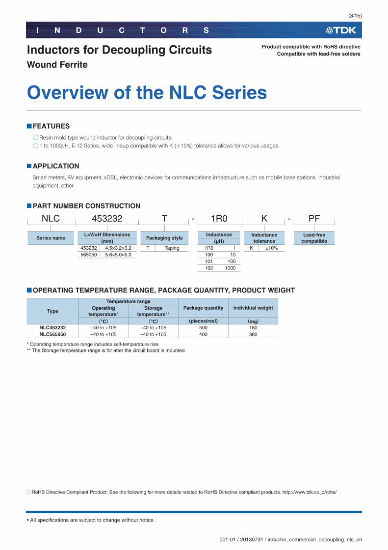
Inductors for Decoupling CircuitsWound Ferrite
FEATURES
Resin mold type wound inductor for decoupling circuits.1 to 1000μH, E-12 Series, wide lineup compatible with K (±10%) tolerance allows for various usages.
APPLICATION
Smart meters, AV equipment, xDSL, electronic devices for communications infrastructure such as mobile base stations, industrial equipment, other
PART NUMBER CONSTRUCTION
OPERATING TEMPERATURE RANGE, PACKAGE QUANTITY, PRODUCT WEIGHT
��Operating temperature range includes self-temperature rise.���The Storage temperature range is for after the circuit board is mounted.
Product compatible with RoHS directiveCompatible with lead-free solders
Overview of the NLC Series
NLC 453232 T - 1R0 K - PF
Series nameL×W×H Dimensions
Packaging styleInductance Inductance
toleranceLead-free
compatible(mm) (μH)453232 4.5×3.2×3.2 T Taping 1R0 1 K ±10%565050 5.6×5.0×5.0 100 10
101 100102 1000
Type
Temperature rangePackage quantity Individual weightOperating
temperature�Storage
temperature��
(°C) (°C) (pieces/reel) (mg)NLC453232 –40 to +105 –40 to +105 500 180NLC565050 –40 to +105 –40 to +105 400 380
RoHS Directive Compliant Product: See the following for more details related to RoHS Directive compliant products. http://www.tdk.co.jp/rohs/

(4/15)
I N D U C T O R S
001-01 / 20130731 / inductor_commercial_decoupling_nlc_en.fm
• All specifications are subject to change without notice.
Overview of the NLC Series
RECOMMENDED REFLOW PROFILE
Preheating Soldering PeakTemp. Time Temp. Time Temp. TimeT1 T2 t1 T3 t2 T4 t3150°C 180°C 90 to 120s 230°C 40s 255°C 10s max.
Naturalcooling
t3
t1
Preheating
t2
Soldering
T3 T3
T4
T2
T1
t: Time
Peak
T: T
empe
ratu
re

(5/15)
I N D U C T O R S
001-01 / 20130731 / inductor_commercial_decoupling_nlc_en.fm
• All specifications are subject to change without notice.
NLC series
NLC453232 TypeSHAPE & DIMENSIONS
RECOMMENDED LAND PATTERN
Dimensions in mm
R0.2
C0.54.5±0.3
3.2
±0.2
3.2
±0.2
2.6±
0.1
0.5 (3.3) (0.6)(0.6)
120
Dimensions in mm
2.8
1.531.5

(6/15)
I N D U C T O R S
001-01 / 20130731 / inductor_commercial_decoupling_nlc_en.fm
• All specifications are subject to change without notice.
NLC series NLC453232 TypeELECTRICAL CHARACTERISTICS
CHARACTERISTICS SPECIFICATION TABLE
�� Rated current: smaller value of either Idc1 or Idc2.Idc1: When based on the inductance change rate (10% below the initial L value)Idc2: When based on the temperature increase (Temperature increase of 20°C by self heating)
○Measurement equipment
* Equivalent measurement equipment may be used.
L Qmin.
L, Q measuring frequency(MHz)
DC resistance (��max.
Rated current�
(mA) Part No.(μH) Tolerance max.
1 ±10% 10 7.96 0.11 1050 NLC453232T-1R0K-PF1.2 ±10% 10 7.96 0.12 1000 NLC453232T-1R2K-PF1.5 ±10% 10 7.96 0.15 950 NLC453232T-1R5K-PF1.8 ±10% 10 7.96 0.16 900 NLC453232T-1R8K-PF2.2 ±10% 10 7.96 0.18 850 NLC453232T-2R2K-PF2.7 ±10% 10 7.96 0.2 800 NLC453232T-2R7K-PF3.3 ±10% 10 7.96 0.22 750 NLC453232T-3R3K-PF3.9 ±10% 10 7.96 0.24 700 NLC453232T-3R9K-PF4.7 ±10% 10 7.96 0.27 650 NLC453232T-4R7K-PF5.6 ±10% 10 7.96 0.3 650 NLC453232T-5R6K-PF6.8 ±10% 10 7.96 0.35 600 NLC453232T-6R8K-PF8.2 ±10% 10 7.96 0.4 600 NLC453232T-8R2K-PF
10 ±10% 10 2.52 0.5 550 NLC453232T-100K-PF12 ±10% 10 2.52 0.6 500 NLC453232T-120K-PF15 ±10% 10 2.52 0.7 450 NLC453232T-150K-PF18 ±10% 10 2.52 0.8 400 NLC453232T-180K-PF22 ±10% 10 2.52 0.9 370 NLC453232T-220K-PF27 ±10% 10 2.52 1.2 330 NLC453232T-270K-PF33 ±10% 10 2.52 1.4 300 NLC453232T-330K-PF39 ±10% 10 2.52 1.6 280 NLC453232T-390K-PF47 ±10% 10 2.52 1.9 260 NLC453232T-470K-PF56 ±10% 10 2.52 2.2 240 NLC453232T-560K-PF68 ±10% 10 2.52 2.6 220 NLC453232T-680K-PF82 ±10% 10 2.52 3.5 200 NLC453232T-820K-PF
100 ±10% 20 0.796 4 180 NLC453232T-101K-PF120 ±10% 20 0.796 4.5 160 NLC453232T-121K-PF150 ±10% 20 0.796 6.5 140 NLC453232T-151K-PF180 ±10% 20 0.796 7.5 120 NLC453232T-181K-PF220 ±10% 20 0.796 9 120 NLC453232T-221K-PF270 ±10% 20 0.796 11 100 NLC453232T-271K-PF330 ±10% 20 0.796 13 90 NLC453232T-331K-PF
Measurement item Product No. ManufacturerL, Q 4194A+16085A+16093B Agilent TechnologiesDC resistance VP-2941A Panasonic
(7/15)
I N D U C T O R S
001-01 / 20130731 / inductor_commercial_decoupling_nlc_en.fm
• All specifications are subject to change without notice.
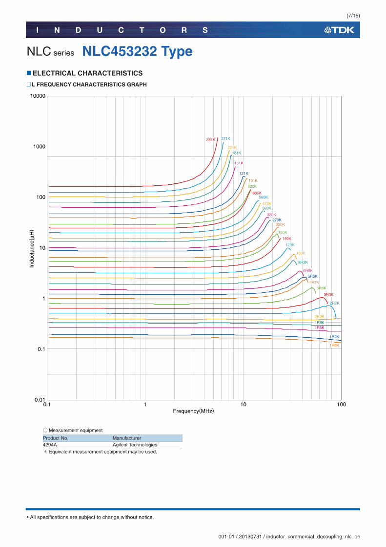
NLC series NLC453232 TypeELECTRICAL CHARACTERISTICS
L FREQUENCY CHARACTERISTICS GRAPH
○Measurement equipment
* Equivalent measurement equipment may be used.
0.1 101 1000.01
0.1
10000
100
1000
1
10
Frequency(MHz)
Indu
ctan
ce( μ
H)
331K 271K
221K181K
151K
121K
101K
680K560K
470K390K
270K220K
150K
3R9K
8R2K
100K
120K
4R7K
5R6K
6R8K
3R3K
2R7K
1R0K
2R2K
1R8K1R5K
1R2K
820K
180K
330K
Product No. Manufacturer4294A Agilent Technologies
(8/15)
I N D U C T O R S
001-01 / 20130731 / inductor_commercial_decoupling_nlc_en.fm
• All specifications are subject to change without notice.
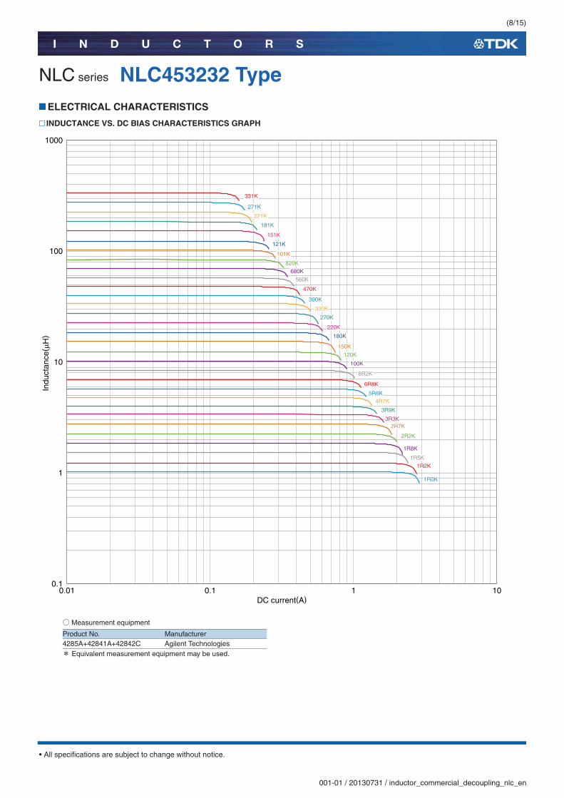
NLC series NLC453232 TypeELECTRICAL CHARACTERISTICS
INDUCTANCE VS. DC BIAS CHARACTERISTICS GRAPH
○Measurement equipment
* Equivalent measurement equipment may be used.
0.01 0.1 1 100.1
10
1
100
1000
DC current(A)
Indu
ctan
ce( μ
H)
331K
271K
221K
181K
151K
121K
101K
820K680K
560K
470K
390K
330K
270K
220K
180K
150K120K
100K
8R2K
6R8K
5R6K4R7K
3R9K
3R3K2R7K
2R2K
1R8K
1R5K1R2K
1R0K
Product No. Manufacturer4285A+42841A+42842C Agilent Technologies
(9/15)
I N D U C T O R S
001-01 / 20130731 / inductor_commercial_decoupling_nlc_en.fm
• All specifications are subject to change without notice.
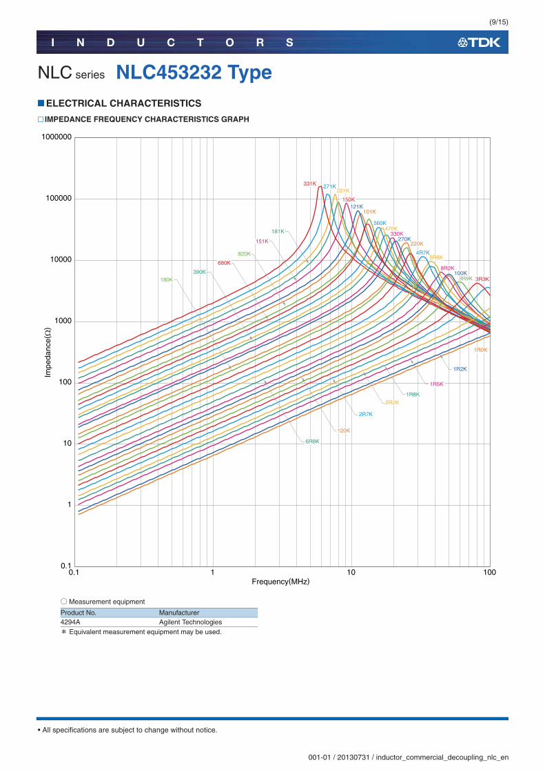
NLC series NLC453232 TypeELECTRICAL CHARACTERISTICS
IMPEDANCE FREQUENCY CHARACTERISTICS GRAPH
○Measurement equipment
* Equivalent measurement equipment may be used.
0.1 101 1000.1
1000000
100000
100
1000
10000
1
10
Impe
danc
e(Ω
)
Frequency(MHz)
331K 271K221K
121K101K
181K
151K
560K470K
220K270K
180K
680K
390K
330K
150K
4R7K5R6K
8R2K
3R9K 3R3K
1R0K
6R8K
100K
120K
2R2K
1R8K
1R5K
1R2K
2R7K
820K
Product No. Manufacturer4294A Agilent Technologies

(10/15)
I N D U C T O R S
001-01 / 20130731 / inductor_commercial_decoupling_nlc_en.fm
• All specifications are subject to change without notice.
NLC series
NLC565050 TypeSHAPE & DIMENSIONS
RECOMMENDED LAND PATTERN
Dimensions in mm
5.6±0.3
5±
0.3
5±
0.3
C1
4±0.
2
1 (4.6) (0.5)(0.5)
470
Dimensions in mm
4.5
242
(11/15)
I N D U C T O R S
001-01 / 20130731 / inductor_commercial_decoupling_nlc_en.fm
• All specifications are subject to change without notice.
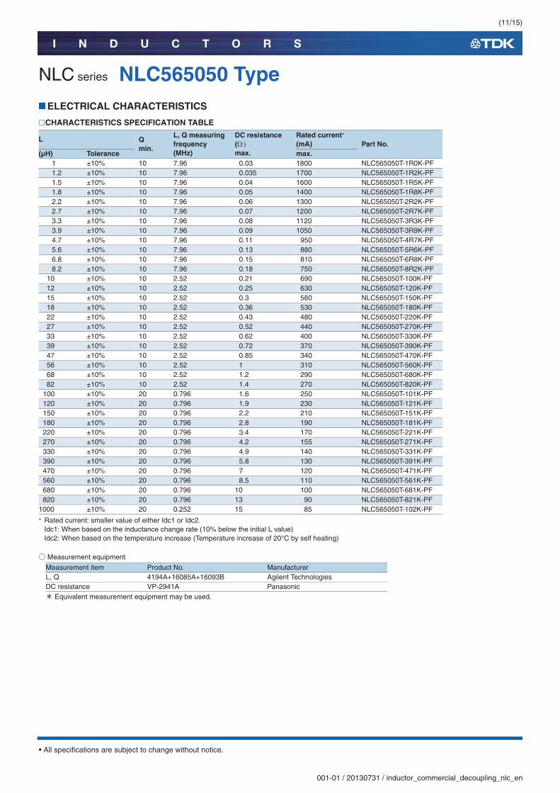
NLC series NLC565050 TypeELECTRICAL CHARACTERISTICS
CHARACTERISTICS SPECIFICATION TABLE
�� Rated current: smaller value of either Idc1 or Idc2.Idc1: When based on the inductance change rate (10% below the initial L value)Idc2: When based on the temperature increase (Temperature increase of 20°C by self heating)
○Measurement equipment
* Equivalent measurement equipment may be used.
L Qmin.
L, Q measuring frequency(MHz)
DC resistance (��max.
Rated current�
(mA) Part No.(μH) Tolerance max.
1 ±10% 10 7.96 0.03 1800 NLC565050T-1R0K-PF1.2 ±10% 10 7.96 0.035 1700 NLC565050T-1R2K-PF1.5 ±10% 10 7.96 0.04 1600 NLC565050T-1R5K-PF1.8 ±10% 10 7.96 0.05 1400 NLC565050T-1R8K-PF2.2 ±10% 10 7.96 0.06 1300 NLC565050T-2R2K-PF2.7 ±10% 10 7.96 0.07 1200 NLC565050T-2R7K-PF3.3 ±10% 10 7.96 0.08 1120 NLC565050T-3R3K-PF3.9 ±10% 10 7.96 0.09 1050 NLC565050T-3R9K-PF4.7 ±10% 10 7.96 0.11 950 NLC565050T-4R7K-PF5.6 ±10% 10 7.96 0.13 880 NLC565050T-5R6K-PF6.8 ±10% 10 7.96 0.15 810 NLC565050T-6R8K-PF8.2 ±10% 10 7.96 0.18 750 NLC565050T-8R2K-PF
10 ±10% 10 2.52 0.21 690 NLC565050T-100K-PF12 ±10% 10 2.52 0.25 630 NLC565050T-120K-PF15 ±10% 10 2.52 0.3 580 NLC565050T-150K-PF18 ±10% 10 2.52 0.36 530 NLC565050T-180K-PF22 ±10% 10 2.52 0.43 480 NLC565050T-220K-PF27 ±10% 10 2.52 0.52 440 NLC565050T-270K-PF33 ±10% 10 2.52 0.62 400 NLC565050T-330K-PF39 ±10% 10 2.52 0.72 370 NLC565050T-390K-PF47 ±10% 10 2.52 0.85 340 NLC565050T-470K-PF56 ±10% 10 2.52 1 310 NLC565050T-560K-PF68 ±10% 10 2.52 1.2 290 NLC565050T-680K-PF82 ±10% 10 2.52 1.4 270 NLC565050T-820K-PF
100 ±10% 20 0.796 1.6 250 NLC565050T-101K-PF120 ±10% 20 0.796 1.9 230 NLC565050T-121K-PF150 ±10% 20 0.796 2.2 210 NLC565050T-151K-PF180 ±10% 20 0.796 2.8 190 NLC565050T-181K-PF220 ±10% 20 0.796 3.4 170 NLC565050T-221K-PF270 ±10% 20 0.796 4.2 155 NLC565050T-271K-PF330 ±10% 20 0.796 4.9 140 NLC565050T-331K-PF390 ±10% 20 0.796 5.8 130 NLC565050T-391K-PF470 ±10% 20 0.796 7 120 NLC565050T-471K-PF560 ±10% 20 0.796 8.5 110 NLC565050T-561K-PF680 ±10% 20 0.796 10 100 NLC565050T-681K-PF820 ±10% 20 0.796 13 90 NLC565050T-821K-PF
1000 ±10% 20 0.252 15 85 NLC565050T-102K-PF
Measurement item Product No. ManufacturerL, Q 4194A+16085A+16093B Agilent TechnologiesDC resistance VP-2941A Panasonic

(12/15)
I N D U C T O R S
001-01 / 20130731 / inductor_commercial_decoupling_nlc_en.fm
• All specifications are subject to change without notice.
NLC series NLC565050 TypeELECTRICAL CHARACTERISTICS
L FREQUENCY CHARACTERISTICS GRAPH
○Measurement equipment
* Equivalent measurement equipment may be used.
0.1 101 1000. 1
10000
100
1000
1
10
Frequency(MHz)
Indu
ctan
ce( μ
H)
102K
821K561K
471K391K
271K221K
181K
681K 331K
151K121K
820K
680K
560K
390K
270K
101K
470K
330K
220K
180K
150K120K
100K
8R2K
5R6K
3R9K
6R8K
4R7K
3R3K
2R7K
2R2K1R8K
1R5K
1R2K
1R0K
Product No. Manufacturer4294A Agilent Technologies

(13/15)
I N D U C T O R S
001-01 / 20130731 / inductor_commercial_decoupling_nlc_en.fm
• All specifications are subject to change without notice.
NLC series NLC565050 TypeELECTRICAL CHARACTERISTICS
INDUCTANCE VS. DC BIAS CHARACTERISTICS GRAPH
○Measurement equipment
* Equivalent measurement equipment may be used.
0.01 0.1 1 100.1
10
1
100
10000
1000
DC current(A)
Indu
ctan
ce( μ
H)
102K
821K681K
561K471K
391K331K
271K181K
221K151K
121K
820K101K
680K
560K470K
390K330K
270K220K
180K150K120K
100K8R2K
6R8K5R6K
4R7K3R9K
3R3K2R7K
2R2K1R8K
1R5K1R2K
1R0K
Product No. Manufacturer4285A+42841A+42842C Agilent Technologies

(14/15)
I N D U C T O R S
001-01 / 20130731 / inductor_commercial_decoupling_nlc_en.fm
• All specifications are subject to change without notice.
NLC series NLC565050 TypeELECTRICAL CHARACTERISTICS
IMPEDANCE FREQUENCY CHARACTERISTICS GRAPH
○Measurement equipment
* Equivalent measurement equipment may be used.
0.1 101 1000.1
1000000
100
1000
10000
100000
1
10
Impe
danc
e(Ω
)
Frequency(MHz)
102K 821K681K
391K181K
271K
151K121K
820K560K
390K270K
680K
220K150K
120K100K
3R9K
8R2K
6R8K
5R6K
3R3K2R7K
1R8K
1R0K
470K
330K
180K
4R7K
2R2K
1R5K
1R2K
561K
471K
221K
331K
101K
Product No. Manufacturer4294A Agilent Technologies

(15/15)
I N D U C T O R S
001-01 / 20130731 / inductor_commercial_decoupling_nlc_en.fm
• All specifications are subject to change without notice.
NLC series
Packaging StyleREEL DIMENSIONS
* These values are typical values.
TAPE DIMENSIONS
Type A W1 W2 N ENLC453232 ø180 13 17 ø60 0.5NLC565050 ø180 13 17 ø60 0.5
ø13.0±0.5
ø21.0±0.8
2.0±0.5
A
(1.0)
Dimensions in mm
N
E
W2
W1
FE
W
P0P2øD0 P1
A t
B
K
Dimensions in mm
Type A B øD0 E F P0 P1 P2 W K tNLC453232 3.6 4.9 1.5+0.1/-0 1.75±0.1 5.50±0.05 4.00±0.10 8.00±0.10 2.00±0.05 12.0±0.30 3.2 0.4NLC565050 5.4 5.8 1.5+0.1/-0 1.75±0.1 5.50±0.05 4.00±0.10 8.00±0.10 2.00±0.05 12.0±0.30 5.4 0.4

Mouser Electronics
Authorized Distributor
Click to View Pricing, Inventory, Delivery & Lifecycle Information: TDK:
NLC565050T-100K-PF NLC565050T-2R2K-PF NLC565050T-3R3K-PF NLC565050T-4R7K-PF NLC565050T-101K-
PF NLC565050T-1R0K-PF NLC565050T-1R2K-PF NLC565050T-270K-PF NLC565050T-102K-PF NLC565050T-
6R8K-PF NLC565050T-221K-PF NLC565050T-1R8K-PF NLC565050T-2R7K-PF NLC565050T-3R9K-PF
NLC565050T-5R6K-PF NLC565050T-8R2K-PF NLC565050T-120K-PF NLC565050T-150K-PF NLC565050T-180K-
PF NLC565050T-220K-PF NLC565050T-330K-PF NLC565050T-390K-PF NLC565050T-470K-PF NLC565050T-
560K-PF NLC565050T-680K-PF NLC565050T-820K-PF NLC565050T-121K-PF NLC565050T-151K-PF
NLC565050T-181K-PF NLC565050T-271K-PF NLC565050T-331K-PF NLC565050T-391K-PF NLC565050T-471K-PF
NLC565050T-561K-PF NLC565050T-681K-PF NLC565050T-821K-PF NLC565050T-1R5K-PF