Embed Size (px)
Citation preview
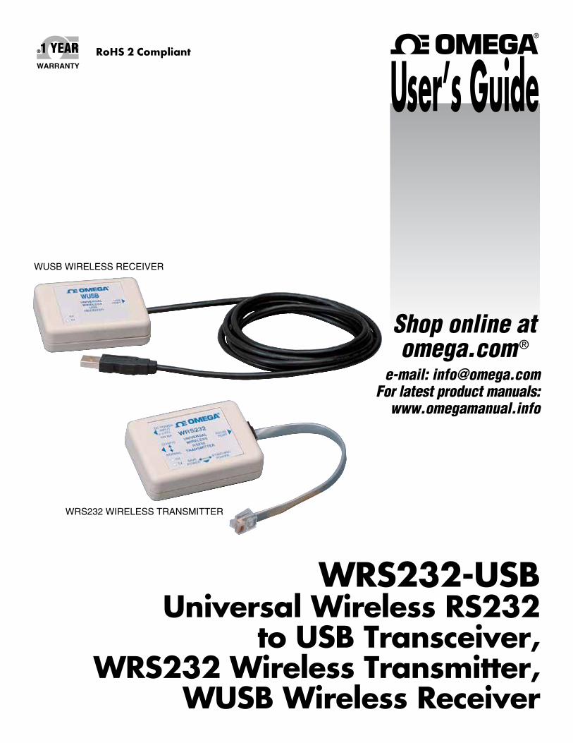
WRS232-USBUniversal Wireless RS232
to USB Transceiver, WRS232 Wireless Transmitter,
WUSB Wireless Receiver
WUSB WIRELESS RECEIVER
WRS232 WIRELESS TRANSMITTER
e-mail: [email protected] For latest product manuals:
www.omegamanual.info
Shop online at omega.com ®
User’s GuideRoHS 2 Compliant

The information contained in this document is believed to be correct, but OMEGA accepts no liability for any errors it contains, and reserves the right to alter specifications without notice.WARNING: These products are not designed for use in, and should not be used for, human applications.
Servicing North America:U.S.A.: Omega Engineering, Inc., One Omega Drive, P.O. Box 4047 Stamford, CT 06907-0047 USA
Toll-Free: 1-800-826-6342 (USA & Canada only) Customer Service: 1-800-622-2378 (USA & Canada only) Engineering Service: 1-800-872-9436 (USA & Canada only) Tel: (203) 359-1660 Fax: (203) 359-7700 e-mail: [email protected]
For Other Locations Visit omega.com/worldwide
omega.com [email protected]
Table of ContentsSection PageSection 1 Introduction ........................................................................................ 1-1
1.1 Precautions ................................................................................................ 1-11.2 Safety Warnings and IEC Symbols ...................................................... 1-11.3 Statement on FCC and Marking .................................................... 1-21.4 General Description & System Components ..................................... 1-2
Section 2 Setup and Configuration ................................................................ 2-12.1 USB Driver Installation ........................................................................... 2-12.2 Wireless Transmitter Module ............................................................... 2-3 2.2.1 Mounting Bracket ........................................................................... 2-4
Section 3 Transmitter/Receiver Configuration ............................................ 3-13.1 Multiple Transmitters ............................................................................. 3-13.2 Environment/Operating Conditions .................................................... 3-23.3 Determining and Maximizing Range .................................................. 3-33.4 Operating in Buildings ........................................................................... 3-4 3.5 Building Materials ................................................................................... 3-43.6 Penetration Angle of Radio Waves through Walls ........................... 3-4
Section 4 Specifications .................................................................................... 4-1Approvals, Regulatory Compliance & Patent Notice ............................. 4-2
i
WRS232-USB Transmitter/Receiver
WRS232-USB Transmitter/Receiver
List of FiguresFigure Description PageSection 1 Introduction Figure 1-1 IEC Symbols ....................................................................................... 1-1 1-2 WRS232 Wireless Transmitter Module ........................................ 1-2 1-3 WUSB Wireless Receiver Module ................................................. 1-3 1-4 FCC Warning Label .......................................................................... 1-3
Section 2 Setup and Configuration Figure 2-1 USB Cable Connection .................................................................... 2-1 2-2 Welcome To The Found New Hardware Wizard Screen .......... 2-2 2-3 Install Software Automatically Screen .......................................... 2-2 2-4 Completing The Found New Hardware Wizard Screen ........... 2-3 2-5 General Dimensions - Mounting Bracket .................................... 2-4 2-6 Transmitter Mounting Bracket Assembly .................................... 2-5 2-7 Transmitter Bracket With 1/4-20 Mounting Screw For Tripod Mount ............................................................................. 2-5 2-8 Transmitter Mounting With DIN Rail Mount Assembly .......... 2-5 2-9 Fresnel Zone ....................................................................................... 2-6
Section 3 Transmitter/Receiver Configuration Figure 3-1 Determining Maximum Range ....................................................... 3-3 3-2 Operation In Buildings .................................................................... 3-4
ii
iii
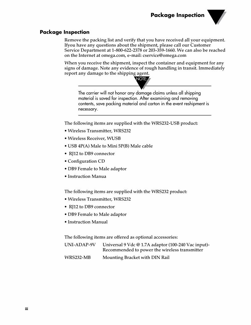
Package InspectionRemove the packing list and verify that you have received all your equipment. Ifyou have any questions about the shipment, please call our Customer Service Department at 1-800-622-2378 or 203-359-1660. We can also be reached on the Internet at omega.com, e-mail: [email protected]
When you receive the shipment, inspect the container and equipment for any signs of damage. Note any evidence of rough handling in transit. Immediately report any damage to the shipping agent.
The carrier will not honor any damage claims unless all shipping material is saved for inspection. After examining and removing contents, save packing material and carton in the event reshipment is necessary.
The following items are supplied with the WRS232-USB product:
• Wireless Transmitter, WRS232
• Wireless Receiver, WUSB
• USB 4P(A) Male to Mini 5P(B) Male cable
• RJ12 to DB9 connector
• Configuration CD
• DB9 Female to Male adaptor
• Instruction Manua
The following items are supplied with the WRS232 product:
• Wireless Transmitter, WRS232
• RJ12 to DB9 connector
• DB9 Female to Male adaptor
• Instruction Manual
The following items are offered as optional accessories:
UNI-ADAP-9V Universal 9 Vdc @ 1.7A adaptor (100-240 Vac input)- Recommended to power the wireless transmitter
WRS232-MB Mounting Bracket with DIN Rail
NOTE:
Package Inspection

NOTES:
iv
Section 1 - IntroductionPlease read this manual completely before installing and operating your wireless connector/transmitter and receiver system. It’s important to read and follow all notes, cautions, warnings and safety precautions before operating this device. “Device” refers to your wireless/transmitter or receiver unit.
1.1 Precautions • This device is not designed for use in any medical or nuclear applications.
• Do not operate this device in flammable or explosive environments.
• Never operate with a power source other than the one recommended in this manual.
• This device has been designed for dry, moisture free indoor applications only.
• Do not operate this device outside of the recommended use outlined in this manual.
• No co-location with other radio transmitters is allowed. By definition, co-location is when another radio device or it’s antenna is located within 20 cm of your device and can transmit simultaneously with your unit.
• Never install the wireless transmitters/receiver within 20 cm or less from each other.
• Never install and/or operate your wireless RS232 transmitter closer than 20 cm to nearby persons.
There are no user serviceable parts inside your device. Attempting to repair or service your unit may void your warranty:
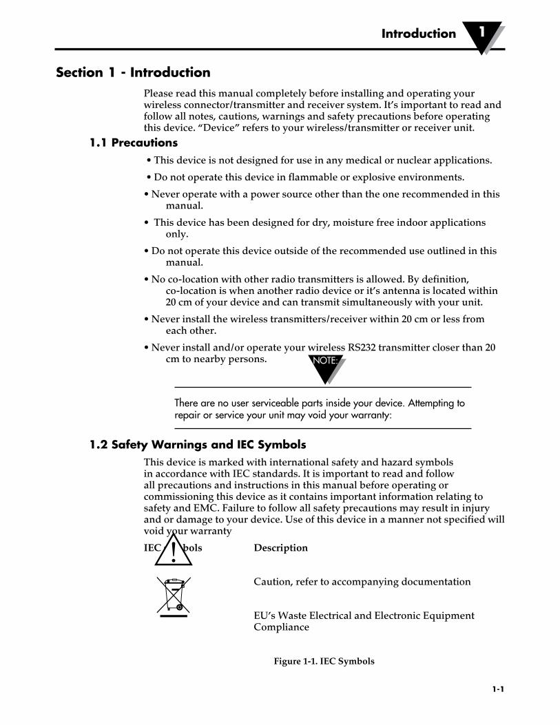
1.2 Safety Warnings and IEC SymbolsThis device is marked with international safety and hazard symbols in accordance with IEC standards. It is important to read and follow all precautions and instructions in this manual before operating or commissioning this device as it contains important information relating to safety and EMC. Failure to follow all safety precautions may result in injury and or damage to your device. Use of this device in a manner not specified will void your warranty
IEC symbols Description
Caution, refer to accompanying documentation
EU’s Waste Electrical and Electronic Equipment Compliance
Figure 1-1. IEC Symbols
1-1
Introduction 1
NOTE:
1.3 Statement on FCC MarkingFCC Marking
FCC ID: OUR-XBEEPRO IC #4214A-EXBEEPRO
This device complies with Part 15 of the FCC rules. Operation is subject to the following two conditions: 1.) This device may not cause harmful interference. 2.) This device must accept any interference received, including interference that may cause undesired operation.
Marking
It is the policy of OMEGA to comply with all worldwide safety and EMI/EMC regulations that apply. OMEGA is constantly pursuing certification of its products to the European New Approach Directives. OMEGA will add the mark to every appropriate device upon certification. For additional information see Section 10 - Approvals & Regulatory Compliance.
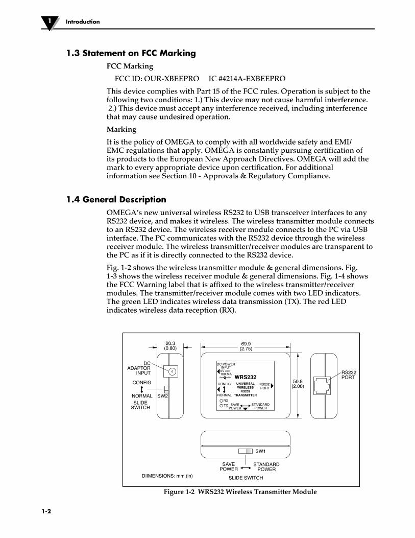
1.4 General DescriptionOMEGA’s new universal wireless RS232 to USB transceiver interfaces to any RS232 device, and makes it wireless. The wireless transmitter module connects to an RS232 device. The wireless receiver module connects to the PC via USB interface. The PC communicates with the RS232 device through the wireless receiver module. The wireless transmitter/receiver modules are transparent to the PC as if it is directly connected to the RS232 device.
Fig. 1-2 shows the wireless transmitter module & general dimensions. Fig. 1-3 shows the wireless receiver module & general dimensions. Fig. 1-4 showsthe FCC Warning label that is affixed to the wireless transmitter/receivermodules. The transmitter/receiver module comes with two LED indicators.The green LED indicates wireless data transmission (TX). The red LEDindicates wireless data reception (RX).
Figure 1-2 WRS232 Wireless Transmitter Module
Introduction1
1-2
– +
DC POWER INPUT 9V 100 MA WRS232
UNIVERSAL WIRELESS
RS232 TRANSMITTER
RS232 PORT
SAVE POWER
SAVE POWER
20.3 (0.80)
69.9 (2.75)
50.8 (2.00)
SLIDE SWITCH
STANDARD POWER
STANDARD POWER
CONFIG
NORMAL RX TX
DC ADAPTOR
INPUT
DIIMENSIONS: mm (in)
RS232 PORT
CONFIG
SLIDE SWITCH
NORMAL SW2
SW1
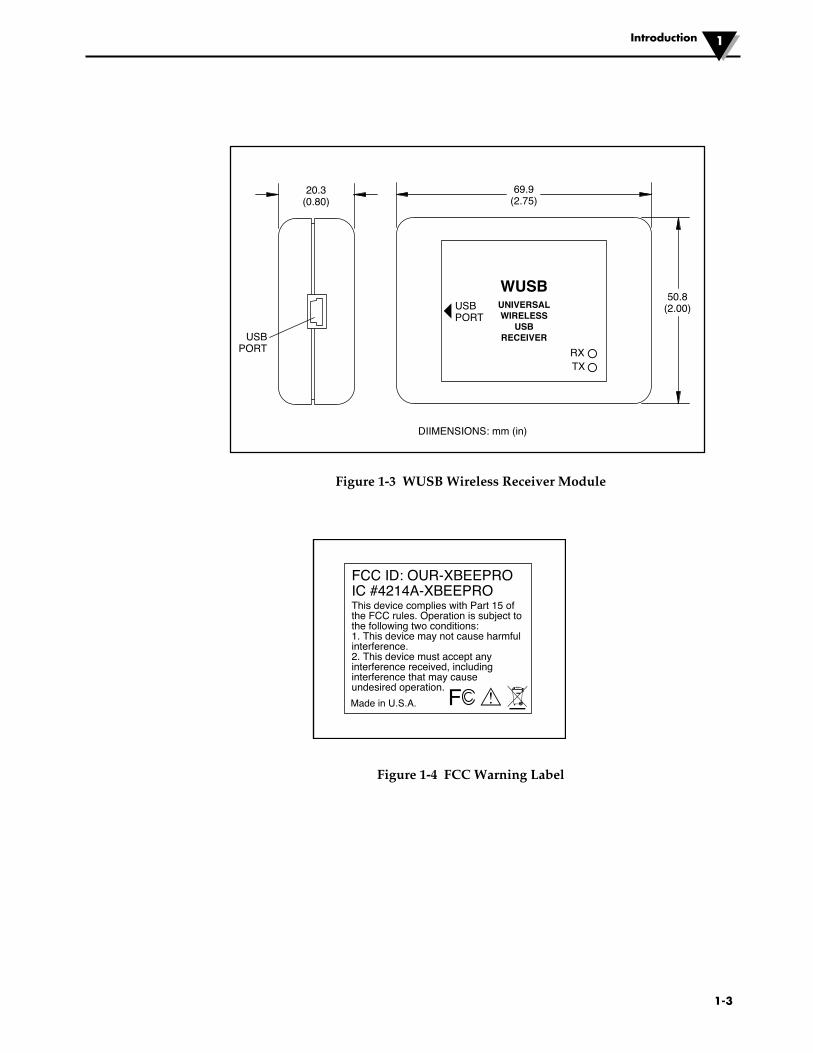
Figure 1-3 WUSB Wireless Receiver Module
Figure 1-4 FCC Warning Label
1-3
20.3 (0.80)
69.9 (2.75)
50.8 (2.00)
USB PORT RX
TX
WUSB UNIVERSAL WIRELESS
USB RECEIVER
USB PORT
DIIMENSIONS: mm (in)
!F
FCC ID: OUR-XBEEPROIC #4214A-XBEEPRO
Made in U.S.A.
This device complies with Part 15 of the FCC rules. Operation is subject to the following two conditions:1. This device may not cause harmful interference.2. This device must accept any interference received, including interference that may cause undesired operation.
Introduction 1
2-1
Setup and Configuration2
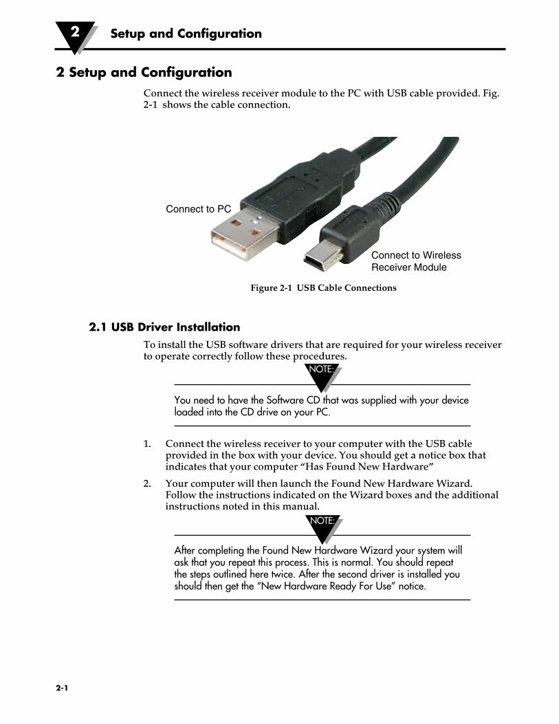
2 Setup and ConfigurationConnect the wireless receiver module to the PC with USB cable provided. Fig. 2-1 shows the cable connection.
Figure 2-1 USB Cable Connections
2.1 USB Driver Installation To install the USB software drivers that are required for your wireless receiver to operate correctly follow these procedures.
You need to have the Software CD that was supplied with your device loaded into the CD drive on your PC.
1. Connect the wireless receiver to your computer with the USB cable provided in the box with your device. You should get a notice box that indicates that your computer “Has Found New Hardware”
2. Your computer will then launch the Found New Hardware Wizard. Follow the instructions indicated on the Wizard boxes and the additional instructions noted in this manual.
After completing the Found New Hardware Wizard your system will ask that you repeat this process. This is normal. You should repeat the steps outlined here twice. After the second driver is installed you should then get the “New Hardware Ready For Use” notice.
NOTE:
NOTE:
Connect to PC
Connect to Wireless Receiver Module
2-2
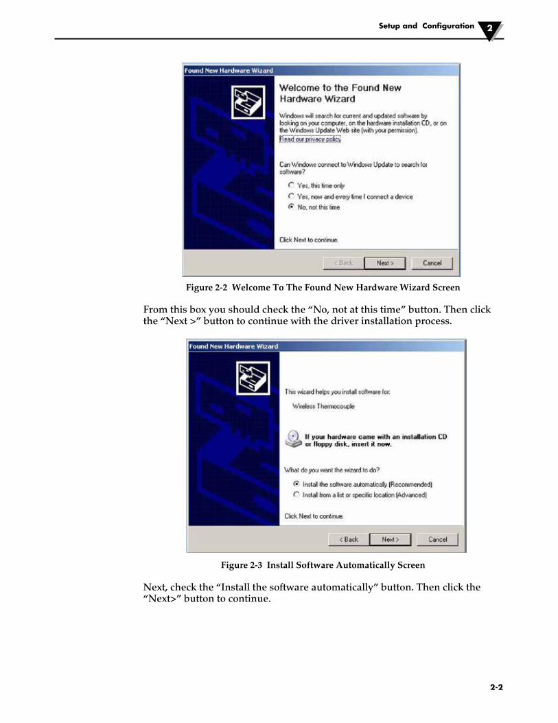
Figure 2-2 Welcome To The Found New Hardware Wizard Screen
From this box you should check the “No, not at this time” button. Then click the “Next >” button to continue with the driver installation process.
Figure 2-3 Install Software Automatically Screen
Next, check the “Install the software automatically” button. Then click the “Next>” button to continue.
Setup and Configuration 2
Setup and Configuration2
2-3
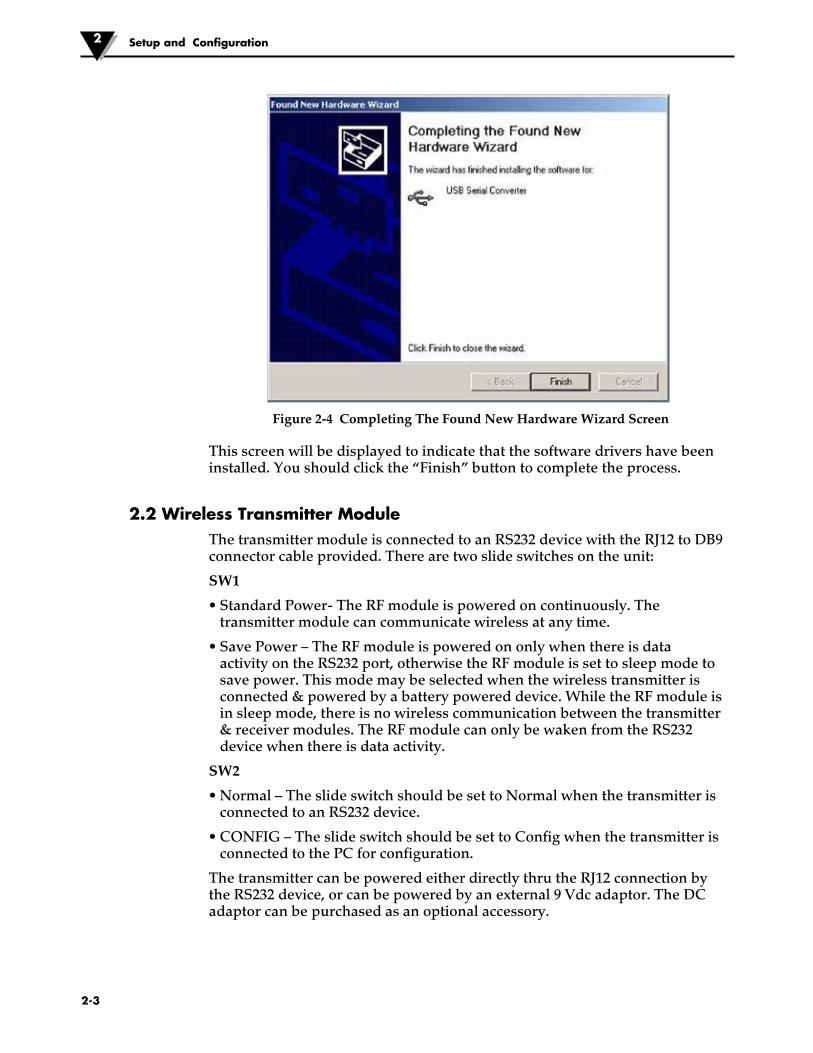
Figure 2-4 Completing The Found New Hardware Wizard Screen
This screen will be displayed to indicate that the software drivers have been installed. You should click the “Finish” button to complete the process.
2.2 Wireless Transmitter ModuleThe transmitter module is connected to an RS232 device with the RJ12 to DB9 connector cable provided. There are two slide switches on the unit:
SW1
• Standard Power- The RF module is powered on continuously. The transmitter module can communicate wireless at any time.
• Save Power – The RF module is powered on only when there is data activity on the RS232 port, otherwise the RF module is set to sleep mode to save power. This mode may be selected when the wireless transmitter is connected & powered by a battery powered device. While the RF module is in sleep mode, there is no wireless communication between the transmitter & receiver modules. The RF module can only be waken from the RS232 device when there is data activity.
SW2
• Normal – The slide switch should be set to Normal when the transmitter is connected to an RS232 device.
• CONFIG – The slide switch should be set to Config when the transmitter is connected to the PC for configuration.
The transmitter can be powered either directly thru the RJ12 connection by the RS232 device, or can be powered by an external 9 Vdc adaptor. The DC adaptor can be purchased as an optional accessory.
Setup and Configuration 2
2-4
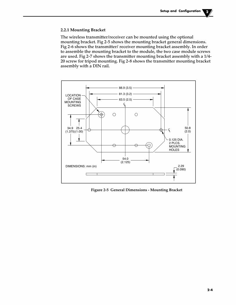
2.2.1 Mounting Bracket
The wireless transmitter/receiver can be mounted using the optional mounting bracket. Fig 2-5 shows the mounting bracket general dimensions. Fig 2-6 shows the transmitter/ receiver mounting bracket assembly. In order to assemble the mounting bracket to the module, the two case module screws are used. Fig 2-7 shows the transmitter mounting bracket assembly with a 1/4-20 screw for tripod mounting. Fig 2-8 shows the transmitter mounting bracket assembly with a DIN rail.
Figure 2-5 General Dimensions - Mounting Bracket
CL
LC
88.9 (3.5)
25.4(1.00)
54.0(2.125)
2.29(0.090)
34.9(1.375)
81.3 (3.2)
63.5 (2.5)
50.8(2.0)
LOCATIONOF CASE
MOUNTINGSCREWS
0.125 DIA.2 PLCS.MOUNTINGHOLES
DIMENSIONS: mm (in)
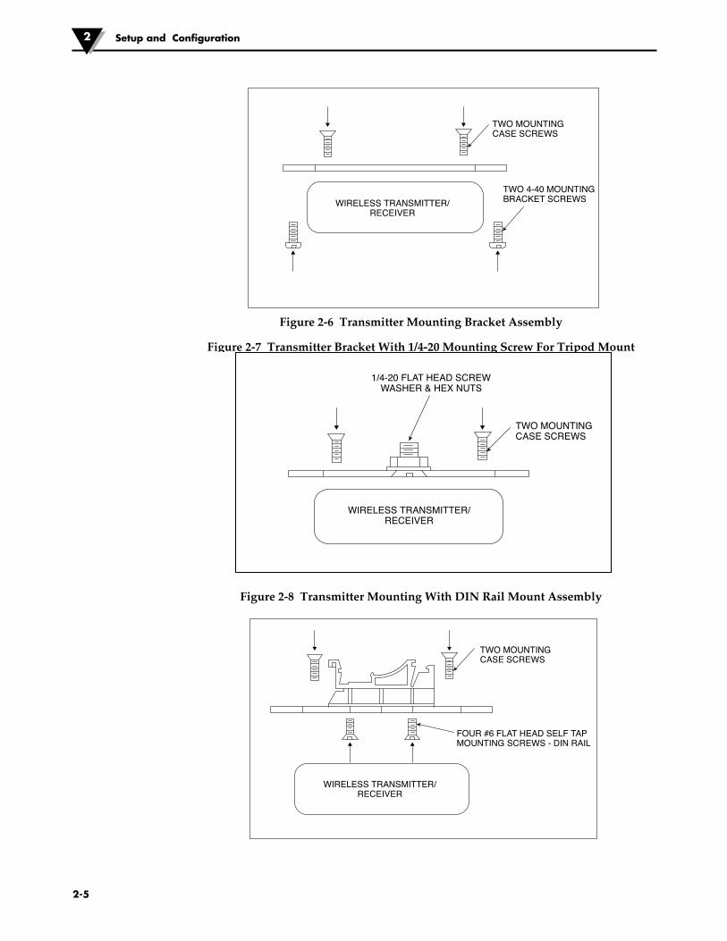
Figure 2-6 Transmitter Mounting Bracket Assembly
Figure 2-7 Transmitter Bracket With 1/4-20 Mounting Screw For Tripod Mount
Figure 2-8 Transmitter Mounting With DIN Rail Mount Assembly
Setup and Configuration2
2-5
TWO MOUNTINGCASE SCREWS
TWO 4-40 MOUNTINGBRACKET SCREWSWIRELESS TRANSMITTER/
RECEIVER
TWO MOUNTINGCASE SCREWS
1/4-20 FLAT HEAD SCREWWASHER & HEX NUTS
WIRELESS TRANSMITTER/RECEIVER
TWO MOUNTINGCASE SCREWS
FOUR #6 FLAT HEAD SELF TAPMOUNTING SCREWS - DIN RAIL
WIRELESS TRANSMITTER/RECEIVER
When mounting your wireless transmitter, care should be taken to make sure it is as far away from any metal objects. Otherwise, it has the potential to interfere with the way the unit radiates and may cause signal lose or possibly even the inability to communicate at all with your receiver.
When installing your wireless transmitter it is important to position your device in such a way as to optimize the antenna location within what’s known as the “Fresnel Zone”.
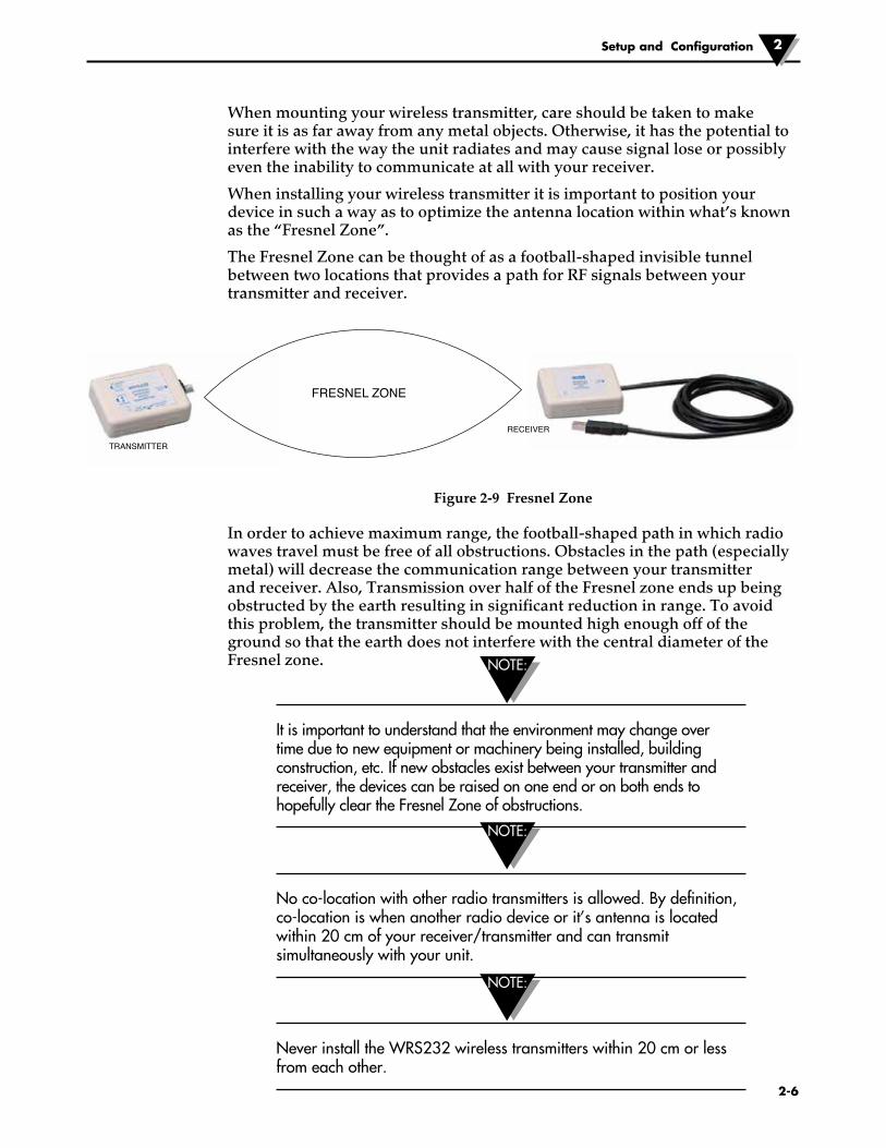
The Fresnel Zone can be thought of as a football-shaped invisible tunnel between two locations that provides a path for RF signals between your transmitter and receiver.
Figure 2-9 Fresnel Zone
In order to achieve maximum range, the football-shaped path in which radio waves travel must be free of all obstructions. Obstacles in the path (especially metal) will decrease the communication range between your transmitter and receiver. Also, Transmission over half of the Fresnel zone ends up being obstructed by the earth resulting in significant reduction in range. To avoid this problem, the transmitter should be mounted high enough off of the ground so that the earth does not interfere with the central diameter of the Fresnel zone.
It is important to understand that the environment may change over time due to new equipment or machinery being installed, building construction, etc. If new obstacles exist between your transmitter and receiver, the devices can be raised on one end or on both ends to hopefully clear the Fresnel Zone of obstructions.
No co-location with other radio transmitters is allowed. By definition, co-location is when another radio device or it’s antenna is located within 20 cm of your receiver/transmitter and can transmit simultaneously with your unit.
Never install the WRS232 wireless transmitters within 20 cm or less from each other.
Setup and Configuration 2
2-6
FRESNEL ZONE
TRANSMITTER
RECEIVER
NOTE:
NOTE:
NOTE:
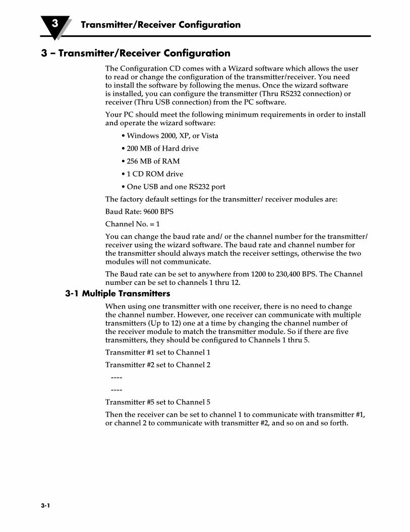
3 – Transmitter/Receiver ConfigurationThe Configuration CD comes with a Wizard software which allows the user to read or change the configuration of the transmitter/receiver. You need to install the software by following the menus. Once the wizard software is installed, you can configure the transmitter (Thru RS232 connection) or receiver (Thru USB connection) from the PC software.
Your PC should meet the following minimum requirements in order to install and operate the wizard software:
• Windows 2000, XP, or Vista
• 200 MB of Hard drive
• 256 MB of RAM
• 1 CD ROM drive
• One USB and one RS232 port
The factory default settings for the transmitter/ receiver modules are:
Baud Rate: 9600 BPS
Channel No. = 1
You can change the baud rate and/ or the channel number for the transmitter/ receiver using the wizard software. The baud rate and channel number for the transmitter should always match the receiver settings, otherwise the two modules will not communicate.
The Baud rate can be set to anywhere from 1200 to 230,400 BPS. The Channel number can be set to channels 1 thru 12.
3-1 Multiple TransmittersWhen using one transmitter with one receiver, there is no need to change the channel number. However, one receiver can communicate with multiple transmitters (Up to 12) one at a time by changing the channel number of the receiver module to match the transmitter module. So if there are five transmitters, they should be configured to Channels 1 thru 5.
Transmitter #1 set to Channel 1
Transmitter #2 set to Channel 2
----
----
Transmitter #5 set to Channel 5
Then the receiver can be set to channel 1 to communicate with transmitter #1, or channel 2 to communicate with transmitter #2, and so on and so forth.
3-1
Transmitter/Receiver Configuration3
3.2 Environment/Operating ConditionsThe wireless transmitter and receiver modules have been designed to be operated in a clean and dry indoor environment. Care should be taken to prevent the components of your wireless system from being exposed to moisture, toxic chemicals and extreme cold or hot temperature that are outside the specifications listed in this manual.
3.2.1 Operating Conditions
The following is a list of basic good practice you should apply when operating your wireless system.
• Never operate your wireless device outside the recommended environmental limits specified in this manual.
• Never operate your wireless device in flammable or explosive environments.
• Never use your wireless device in medical, nuclear or other other dangerous applications were failure can cause damage or harm.
• No co-location with other radio transmitters is allowed. By definition, co-location is when another radio device or it’s antenna is located within 20 cm of your transmitter and can transmit simultaneously with your unit.
• Never install receiver/transmitters within 20 cm or less from each other.
• Never install and/or operate your transmitter/receiver closer than 20 cm to nearby persons.
Transmitter/Receiver Configuration 3
3-2
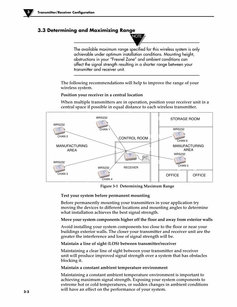
3.3 Determining and Maximizing Range
The available maximum range specified for this wireless system is only achievable under optimum installation conditions. Mounting height, obstructions in your “Fresnel Zone” and ambient conditions can affect the signal strength resulting in a shorter range between your transmitter and receiver unit.
The following recommendations will help to improve the range of your wireless system.
Position your receiver in a central location
When multiple transmitters are in operation, position your receiver unit in a central space if possible in equal distance to each wireless transmitter.
Figure 3-1 Determining Maximum Range
Test your system before permanent mounting
Before permanently mounting your transmitters in your application try moving the devices to different locations and mounting angles to determine what installation achieves the best signal strength.
Move your system components higher off the floor and away from exterior walls
Avoid installing your system components too close to the floor or near your buildings exterior walls. The closer your transmitter and receiver unit are the greater the interference and lose of signal strength will be.
Maintain a line of sight (LOS) between transmitter/receiver
Maintaining a clear line of sight between your transmitter and receiver unit will produce improved signal strength over a system that has obstacles blocking it.
Maintain a constant ambient temperature environment
Maintaining a constant ambient temperature environment is important to achieving maximum signal strength. Exposing your system components to extreme hot or cold temperatures, or sudden changes in ambient conditions will have an effect on the performance of your system.
Transmitter/Receiver Configuration3
3-3
STORAGE ROOM
CONTROL ROOM
OFFICE OFFICE
PC
RECEIVER
WRS232
MANUFACTURINGAREA
MANUFACTURINGAREA
CHAN 2
WRS232
CHAN 1 WRS232
CHAN 6
WRS232
CHAN 5WRS232
CHAN 3
WRS232
CHAN 4
NOTE:
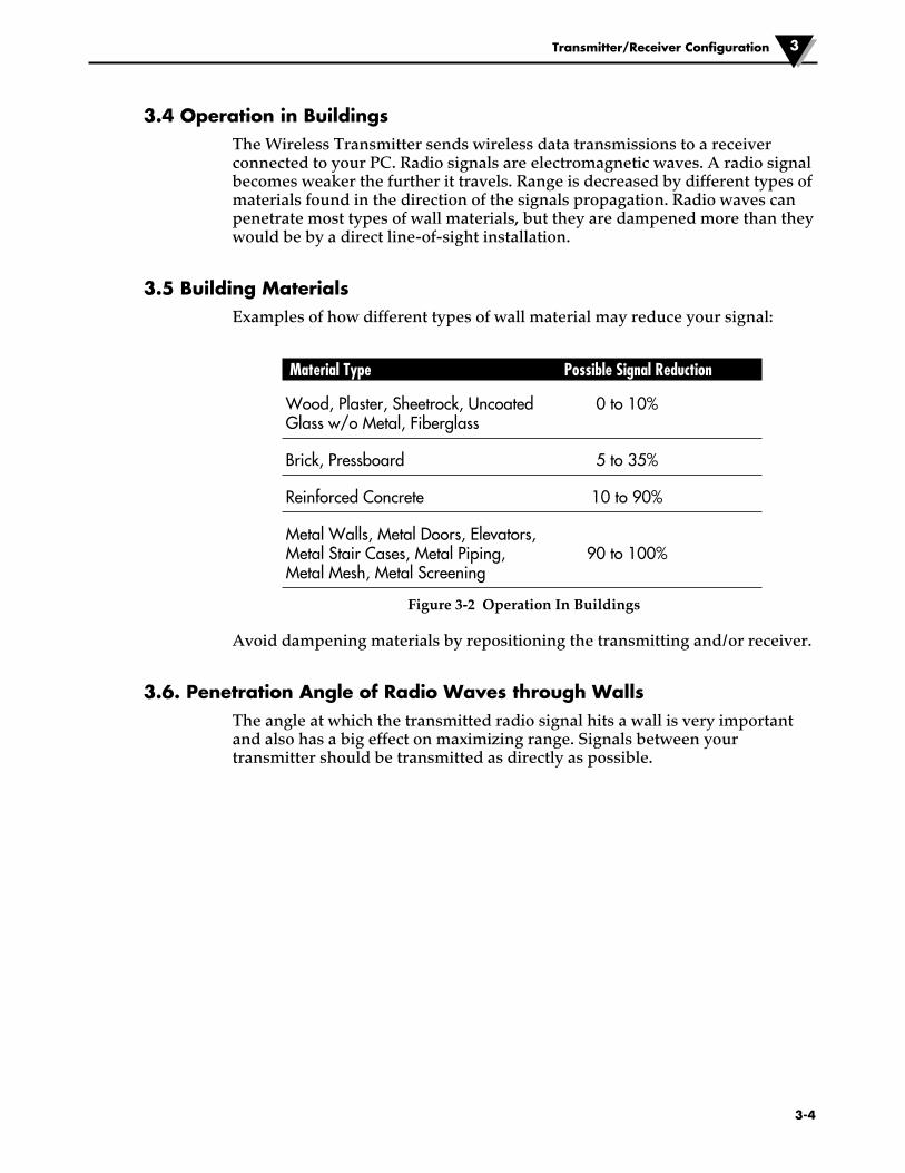
3.4 Operation in BuildingsThe Wireless Transmitter sends wireless data transmissions to a receiver connected to your PC. Radio signals are electromagnetic waves. A radio signal becomes weaker the further it travels. Range is decreased by different types of materials found in the direction of the signals propagation. Radio waves can penetrate most types of wall materials, but they are dampened more than they would be by a direct line-of-sight installation.
3.5 Building MaterialsExamples of how different types of wall material may reduce your signal:
Material Type Possible Signal Reduction
Wood, Plaster, Sheetrock, Uncoated 0 to 10% Glass w/o Metal, Fiberglass
Brick, Pressboard 5 to 35%
Reinforced Concrete 10 to 90%
Metal Walls, Metal Doors, Elevators, Metal Stair Cases, Metal Piping, 90 to 100% Metal Mesh, Metal Screening
Figure 3-2 Operation In Buildings
Avoid dampening materials by repositioning the transmitting and/or receiver.
3.6. Penetration Angle of Radio Waves through WallsThe angle at which the transmitted radio signal hits a wall is very important and also has a big effect on maximizing range. Signals between your transmitter should be transmitted as directly as possible.
Transmitter/Receiver Configuration 3
3-4
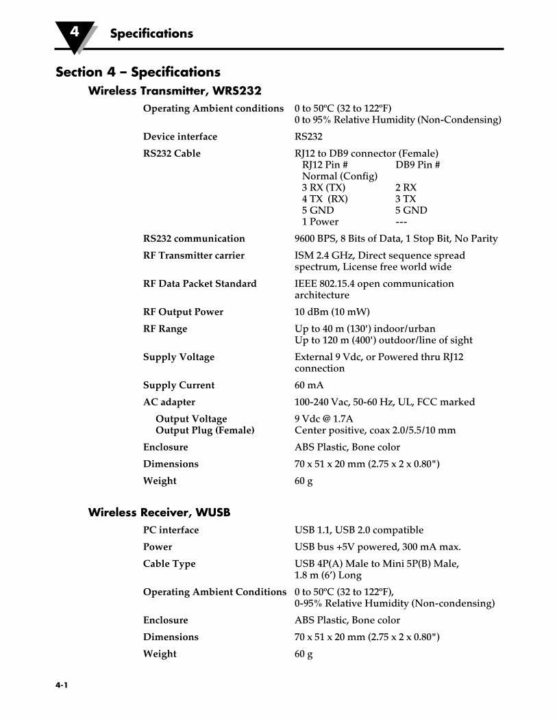
Section 4 – SpecificationsWireless Transmitter, WRS232
Operating Ambient conditions 0 to 50ºC (32 to 122ºF) 0 to 95% Relative Humidity (Non-Condensing)
Device interface RS232
RS232 Cable RJ12 to DB9 connector (Female) RJ12 Pin # DB9 Pin # Normal (Config) 3 RX (TX) 2 RX 4 TX (RX) 3 TX 5 GND 5 GND 1 Power ---
RS232 communication
RF Transmitter carrier
RF Data Packet Standard
RF Output Power
RF Range
Supply Voltage
Supply Current
AC adapter
Output Voltage Output Plug (Female)
Enclosure
Dimensions
Weight
Wireless Receiver, WUSBPC interface
Power
Cable Type
9600 BPS, 8 Bits of Data, 1 Stop Bit, No Parity
ISM 2.4 GHz, Direct sequence spread spectrum, License free world wide
IEEE 802.15.4 open communication architecture
10 dBm (10 mW)
Up to 40 m (130') indoor/urban Up to 120 m (400') outdoor/line of sight
External 9 Vdc, or Powered thru RJ12 connection
60 mA
100-240 Vac, 50-60 Hz, UL, FCC marked
9 Vdc @ 1.7A Center positive, coax 2.0/5.5/10 mm
ABS Plastic, Bone color
70 x 51 x 20 mm (2.75 x 2 x 0.80")
60 g
USB 1.1, USB 2.0 compatible
USB bus +5V powered, 300 mA max.
USB 4P(A) Male to Mini 5P(B) Male, 1.8 m (6’) Long
Operating Ambient Conditions 0 to 50ºC (32 to 122ºF), 0-95% Relative Humidity (Non-condensing)
Enclosure ABS Plastic, Bone color
Dimensions 70 x 51 x 20 mm (2.75 x 2 x 0.80")
Weight 60 g
4-1
Specifications4
Approvals, Regulatory Compliance & Patent NoticeFCC (Domestic Use: USA & Canada)
(USA) FCC ID: OUR-XBEEPRO (CANADA) IC #4214A-EXBEEPRO
This device complies with Part 15 of the FCC rules. Operation is subject to the following two conditions: 1.) This device may not cause harmful interference. 2.) This device must accept any interference received, including interference that may cause undesired operation.
To satisfy FCC RF exposure requirements for mobile transmitting devices, a separation distance of 20 cm or more should be maintained between this device and persons during device operation. To ensure compliance, operations at closer than this distance is not recommended. This transmitter must not be co-located in conjunction with any other transmitter or antenna.
4-2
Approvals and Regulatory Compliance 4
WARNING:

NOTES:
System Operation6
4-3
OMEGA’s policy is to make running changes, not model changes, whenever an improvement is possible. This affords our customers the latest in technology and engineering.OMEGA is a registered trademark of OMEGA ENGINEERING, INC.© Copyright 2014 OMEGA ENGINEERING, INC. All rights reserved. This document may not be copied, photocopied, reproduced, translated, or reduced to any electronic medium or machine-readable form, in whole or in part, without the prior written consent of OMEGA ENGINEERING, INC.
FOR WARRANTY RETURNS, please have the following information available BEFORE contacting OMEGA:1. Purchase Order number under which the product
was PURCHASED,2. Model and serial number of the product under
warranty, and3. Repair instructions and/or specific problems relative to the product.
FOR NON-WARRANTY REPAIRS, consult OMEGA for current repair charges. Have the following information available BEFORE contacting OMEGA:1. Purchase Order number to cover the COST of the repair,2. Model and serial number of the product, and3. Repair instructions and/or specific problems relative to the product.
RETURN REQUESTS/INQUIRIESDirect all warranty and repair requests/inquiries to the OMEGA Customer Service Department. BEFORE RETURNING ANY PRODUCT(S) TO OMEGA, PURCHASER MUST OBTAIN AN AUTHORIZED RETURN (AR) NUMBER FROM OMEGA’S CUSTOMER SERVICE DEPARTMENT (IN ORDER TO AVOID PROCESSING DELAYS). The assigned AR number should then be marked on the outside of the return package and on any correspondence.The purchaser is responsible for shipping charges, freight, insurance and proper packaging to prevent breakage in transit.
WARRANTY/DISCLAIMEROMEGA ENGINEERING, INC. warrants this unit to be free of defects in materials and workmanship for a period of 13 months from date of purchase. OMEGA’s WARRANTY adds an additional one (1) month grace period to the normal one (1) year product warranty to cover handling and shipping time. This ensures that OMEGA’s customers receive maximum coverage on each product. If the unit malfunctions, it must be returned to the factory for evaluation. OMEGA’s Customer Service Department will issue an Authorized Return (AR) number immediately upon phone or written request. Upon examination by OMEGA, if the unit is found to be defective, it will be repaired or replaced at no charge. OMEGA’s WARRANTY does not apply to defects resulting from any action of the purchaser, including but not limited to mishandling, improper interfacing, operation outside of design limits, improper repair, or unauthorized modification. This WARRANTY is VOID if the unit shows evidence of having been tampered with or shows evidence of having been damaged as a result of excessive corrosion; or current, heat, moisture or vibration; improper specification; misapplication; misuse or other operating conditions outside of OMEGA’s control. Components in which wear is not warranted, include but are not limited to contact points, fuses, and triacs.OMEGA is pleased to offer suggestions on the use of its various products. However, OMEGA neither assumes responsibility for any omissions or errors nor assumes liability for any damages that result from the use of its products in accordance with information provided by OMEGA, either verbal or written. OMEGA warrants only that the parts manufactured by the company will be as specified and free of defects. OMEGA MAKES NO OTHER WARRANTIES OR REPRESENTATIONS OF ANY KIND WHATSOEVER, EXPRESSED OR IMPLIED, EXCEPT THAT OF TITLE, AND ALL IMPLIED WARRANTIES INCLUDING ANY WARRANTY OF MERCHANTABILITY AND FITNESS FOR A PARTICULAR PURPOSE ARE HEREBY DISCLAIMED. LIMITATION OF LIABILITY: The remedies of purchaser set forth herein are exclusive, and the total liability of OMEGA with respect to this order, whether based on contract, warranty, negligence, indemnification, strict liability or otherwise, shall not exceed the purchase price of the component upon which liability is based. In no event shall OMEGA be liable for consequential, incidental or special damages.CONDITIONS: Equipment sold by OMEGA is not intended to be used, nor shall it be used: (1) as a “Basic Component” under 10 CFR 21 (NRC), used in or with any nuclear installation or activity; or (2) in medical applications or used on humans. Should any Product(s) be used in or with any nuclear installation or activity, medical application, used on humans, or misused in any way, OMEGA assumes no responsibility as set forth in our basic WARRANTY/DISCLAIMER language, and, additionally, purchaser will indemnify OMEGA and hold OMEGA harmless from any liability or damage whatsoever arising out of the use of the Product(s) in such a manner.

M4588/0308
Where Do I Find Everything I Need for Process Measurement and Control?
OMEGA…Of Course!Shop online at omega.com SM
TEMPERATUREMU Thermocouple, RTD & Thermistor Probes, Connectors, Panels & Assemblies MU Wire: Thermocouple, RTD & ThermistorMU Calibrators & Ice Point ReferencesMU Recorders, Controllers & Process MonitorsMU Infrared Pyrometers
PRESSURE, STRAIN AND FORCEMU Transducers & Strain GagesMU Load Cells & Pressure GagesMU Displacement TransducersMU Instrumentation & Accessories
FLOW/LEVELMU Rotameters, Gas Mass Flowmeters & Flow ComputersMU Air Velocity IndicatorsMU Turbine/Paddlewheel SystemsMU Totalizers & Batch Controllers
pH/CONDUCTIVITYMU pH Electrodes, Testers & AccessoriesMU Benchtop/Laboratory MetersMU Controllers, Calibrators, Simulators & PumpsMU Industrial pH & Conductivity Equipment
DATA ACQUISITIONMU Data Acquisition & Engineering SoftwareMU Communications-Based Acquisition SystemsMU Plug-in Cards for Apple, IBM & CompatiblesMU Data Logging SystemsMU Recorders, Printers & Plotters
HEATERSMU Heating CableMU Cartridge & Strip HeatersMU Immersion & Band HeatersMU Flexible HeatersMU Laboratory Heaters
ENVIRONMENTAL MONITORING AND CONTROLMU Metering & Control InstrumentationMU RefractometersMU Pumps & TubingMU Air, Soil & Water MonitorsMU Industrial Water & Wastewater TreatmentMU pH, Conductivity & Dissolved Oxygen Instruments