Embed Size (px)
Citation preview
FIRE ENDURANCE RATINGS
OF
CLAY BRICK MASONRY
Prepared for:
Western States Clay Products Association
Submitted by:
Jeffrey L. ElderTechnical Committee Chair
Western States Clay Products Association22815 Frampton Avenue
Torrance, CA 90501
December 2008
The material presented in this publication, including technical and engineering data, figures,drawings and tables are for general information only. It should not under any circumstancesbe relied upon for specific applications of Fire Endurance Ratings of Clay Masonry withoutindependent evaluation by a licensed design professional familiar with its specific use andapplication. Anyone making use of this material does so at their own risk and assumes anyand all liability resulting from such use.
The members of Western States Clay Products Association express appreciation to WalterDickey (1908-2002) for his tireless efforts in promoting the clay brick industry. Mr. Dickeyspearheaded the initial production of this publication providing technical and editorial inputthat continues in this printing.
00.FirstPages.qxp 12/1/2008 11:05 AM Page 1
Western States Clay Products Association 2 December 2008
Table of Contents
1.0 Introduction..........................................................................................................................................3
2.0 Fire Resistance Basics.........................................................................................................................3
3.0 Masonry Assemblies............................................................................................................................3
3.1 Adhered Brick Veneer..............................................................................................................3
3.1.1 Test Panel Construction................................................................................................4
3.1.2 Fire Testing...................................................................................................................4
3.1.3 Results..........................................................................................................................4
3.1.4 Conclusion....................................................................................................................4
3.2 Anchored Brick Veneer...........................................................................................................4
3.2.1 Fire Resistance.............................................................................................................5
3.3 Structural Brick Veneer...........................................................................................................5
3.3.1 Fire Resistance.............................................................................................................5
3.4 Structural Load Bearing Brick................................................................................................6
3.4.1 Fire Resistance.............................................................................................................6
4.0 Calculated Fire Endurance Ratings....................................................................................................6
4.1 Rule 1........................................................................................................................................7
4.2 Rule 2......……...........................................................................................................................7
4.3 Rule 3.……................................................................................................................................8
4.4 Rule 4…….................................................................................................................................8
4.5 Rule 5…….................................................................................................................................8
4.6 Rule 6…….................................................................................................................................8
4.7 Rule 7…….................................................................................................................................9
4.8 Rule 8…….................................................................................................................................9
5.0 Considerations.....................................................................................................................................9
APPENDIX — WALL DETAILS……………………………...................................................................................9
A.1 Materials……............................................................................................................................9
A.2 Wall Configuration.................................................................................................................10
A.3 Installation..............................................................................................................................10
A.4 Fire Rated Wall Sections.......................................................................................................10
FIRE ENDURANCE RATINGS OF CLAY BRICK MASONRY
00.FirstPages.qxp 11/18/2008 7:33 AM Page 2
FIRE ENDURANCE RATINGS OF CLAY BRICK MASONRY
Western States Clay Products Association 3 December 2008
1.0 INTRODUCTION
One of the most frequently asked questions ofthe designer is "How do I achieve a 1, 2, 3, or 4-hourfire rating using various clay brick masonryassemblies?"
Intuitively, we are comfortable with clay bricks asa fire resistant material because of their use as a linerin fireplaces and kilns where temperatures exceedthose expected in most construction fires. In addition,we have observed the effect of fires on buildingswhere the only thing to remain standing is the brick.Most designers do not question that brick is non-combustible, or resistant to fire, what they question isthe fire resistance of each of the brick wallconfigurations in hours as it relates to building coderequirements.
For many wall assemblies, the information isavailable from BIA technical Notes 16, and theInternational Building Code Table 720.1. For someassemblies, the designer is allowed to use methodsof calculating fire resistance. Until recently, designershad to rely on ICBO Evaluation Report #5058 toobtain 1 and 2-hour fire ratings for Adhered andAnchored Veneers. Today this information is found inChapter 7 of the International Building Code, Table720.1.
2.0 FIRE RESISTANCE BASICS
Fire resistance refers to the ability of a structureto act as a barrier to the spread of fire and to confineit to the area of origin. Therefore, in addition towithstanding the fire, the intent of the code is toprevent other materials adjacent to the brick fromcombusting after prolonged increased temperaturesfrom fire, flame, or hot gases. Consequently, theassemblies are given a fire rating which is the time ittakes for a prescribed fire on one side of an assemblyto reach an average temperature on its other sidethat would ignite cotton waste (250°F). Refer toASTM E119.
Fire ratings are required for load bearing andnon-load bearing wall assemblies. Load bearingassemblies must be capable of withstanding thesame conditions as the non-load bearing assemblies.In addition, they must be capable of supporting theirprescribed design load for the duration of the fire.
Fire endurance tests alone cannot supply all ofthe data needed for intelligent appraisal of fire ratings
of building elements. There are simply too manydifferent types of assemblies and combinations ofmaterials to classify them all through actual tests.Fortunately, the theory of fire endurance ratings issufficiently advanced to offer guidance in estimatingfire endurance ratings.
The ultimate goal of this guide is to bring togetherin one location all of the approved fire ratings foradhered veneer, anchored veneer, structural brickveneer and load bearing brick. See Table 1.
3.0 MASONRY ASSEMBLIES
Masonry fire resistant assemblies are brokendown into adhered brick veneer, anchored brickveneer, structural brick veneer, and load bearingbrick.
Fire rated assemblies are often required in twodirections. If the fire is on the brick side, the brickassembly must resist flames, heat, and smoke fromentering to the other side of the assembly prior to therated time. If the fire is on the other side, the firerating may be needed to protect occupants in anotherroom or building from the same effects. In mostcases, there is a structure supporting the fireresistant materials and the fire rated assembly isrequired on both sides to protect the structure. If thematerial is the structure as is the case in load bearingand structural brick veneer, the material canadequately provide fire resistance in both directions.
In a veneer system, the stud backing is thestructure and must be protected in both directions.Therefore, brick most commonly provides fireresistance on the exterior side of the stud, andgypsum or some other material provides the fireresistance on the interior face of the stud.
3.1 ADHERED BRICK VENEER
Adhered brick veneer is defined as brick veneersecured and supported through adhesion to anapproved bonding material applied over an approvedbacking. The most common wall assembly is definedby a facing of thin brick between 1/2" to 11/2" inthickness applied over a plaster backing. If thiscombined masonry layer is 13/4", the masonry side ofthe assembly qualifies for a 1-hr fire rating. If themasonry layer is 2" or more, the masonry side of theassembly qualifies for a 2-hr fire rating. In thisassembly, the plaster is applied to metal lath, whichin turn is applied to wood or steel framing.
01.Fire.qxp 11/18/2008 7:27 AM Page 3
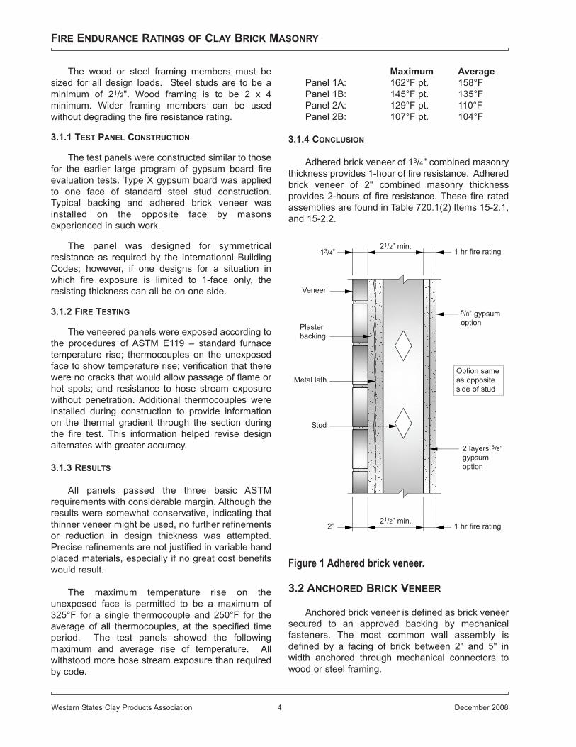
The wood or steel framing members must besized for all design loads. Steel studs are to be aminimum of 21/2". Wood framing is to be 2 x 4minimum. Wider framing members can be usedwithout degrading the fire resistance rating.
3.1.1 TEST PANEL CONSTRUCTION
The test panels were constructed similar to thosefor the earlier large program of gypsum board fireevaluation tests. Type X gypsum board was appliedto one face of standard steel stud construction.Typical backing and adhered brick veneer wasinstalled on the opposite face by masonsexperienced in such work.
The panel was designed for symmetricalresistance as required by the International BuildingCodes; however, if one designs for a situation inwhich fire exposure is limited to 1-face only, theresisting thickness can all be on one side.
3.1.2 FIRE TESTING
The veneered panels were exposed according tothe procedures of ASTM E119 – standard furnacetemperature rise; thermocouples on the unexposedface to show temperature rise; verification that therewere no cracks that would allow passage of flame orhot spots; and resistance to hose stream exposurewithout penetration. Additional thermocouples wereinstalled during construction to provide informationon the thermal gradient through the section duringthe fire test. This information helped revise designalternates with greater accuracy.
3.1.3 RESULTS
All panels passed the three basic ASTMrequirements with considerable margin. Although theresults were somewhat conservative, indicating thatthinner veneer might be used, no further refinementsor reduction in design thickness was attempted.Precise refinements are not justified in variable handplaced materials, especially if no great cost benefitswould result.
The maximum temperature rise on theunexposed face is permitted to be a maximum of325°F for a single thermocouple and 250°F for theaverage of all thermocouples, at the specified timeperiod. The test panels showed the followingmaximum and average rise of temperature. Allwithstood more hose stream exposure than requiredby code.
Maximum AveragePanel 1A: 162°F pt. 158°F Panel 1B: 145°F pt. 135°F Panel 2A: 129°F pt. 110°F Panel 2B: 107°F pt. 104°F
3.1.4 CONCLUSION
Adhered brick veneer of 13/4" combined masonrythickness provides 1-hour of fire resistance. Adheredbrick veneer of 2" combined masonry thicknessprovides 2-hours of fire resistance. These fire ratedassemblies are found in Table 720.1(2) Items 15-2.1,and 15-2.2.
Figure 1 Adhered brick veneer.
3.2 ANCHORED BRICK VENEER
Anchored brick veneer is defined as brick veneersecured to an approved backing by mechanicalfasteners. The most common wall assembly isdefined by a facing of brick between 2" and 5" inwidth anchored through mechanical connectors towood or steel framing.
FIRE ENDURANCE RATINGS OF CLAY BRICK MASONRY
Western States Clay Products Association 4 December 2008
1 hr fire rating21/2” min.
13/4”
5/8” gypsumoption
Option sameas oppositeside of stud
2 layers 5/8”gypsumoption
1 hr fire rating21/2” min.
2”
Veneer
Plasterbacking
Metal lath
Stud
01.Fire.qxp 11/18/2008 7:27 AM Page 4
FIRE ENDURANCE RATINGS OF CLAY BRICK MASONRY
Western States Clay Products Association 5 December 2008
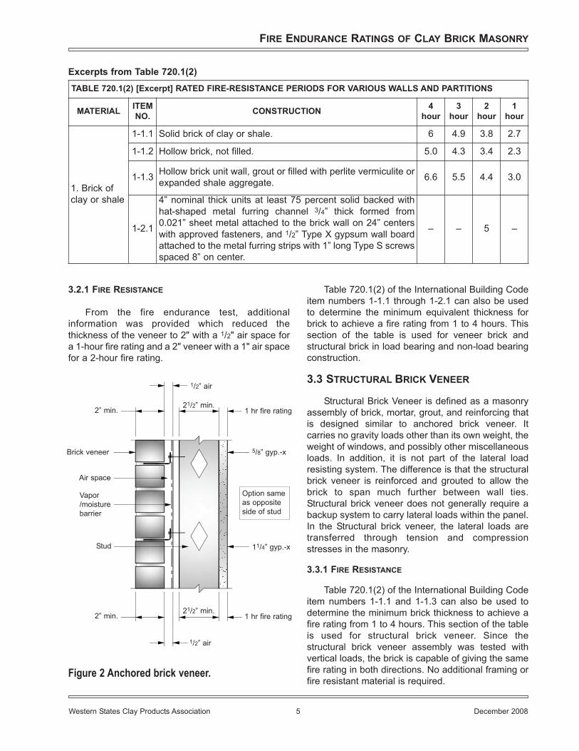
TABLE 720.1(2) [Excerpt] RATED FIRE-RESISTANCE PERIODS FOR VARIOUS WALLS AND PARTITIONS
MATERIAL ITEMNO. CONSTRUCTION 4
hour3
hour2
hour1
hour
1. Brick ofclay or shale
1-1.1 Solid brick of clay or shale. 6 4.9 3.8 2.7
1-1.2 Hollow brick, not filled. 5.0 4.3 3.4 2.3
1-1.3 Hollow brick unit wall, grout or filled with perlite vermiculite orexpanded shale aggregate. 6.6 5.5 4.4 3.0
1-2.1
4” nominal thick units at least 75 percent solid backed withhat-shaped metal furring channel 3/4” thick formed from0.021” sheet metal attached to the brick wall on 24” centerswith approved fasteners, and 1/2” Type X gypsum wall boardattached to the metal furring strips with 1” long Type S screwsspaced 8” on center.
– – 5 –
Excerpts from Table 720.1(2)
3.2.1 FIRE RESISTANCE
From the fire endurance test, additionalinformation was provided which reduced thethickness of the veneer to 2" with a 1/2" air space fora 1-hour fire rating and a 2" veneer with a 1" air spacefor a 2-hour fire rating.
Figure 2 Anchored brick veneer.
Table 720.1(2) of the International Building Codeitem numbers 1-1.1 through 1-2.1 can also be usedto determine the minimum equivalent thickness forbrick to achieve a fire rating from 1 to 4 hours. Thissection of the table is used for veneer brick andstructural brick in load bearing and non-load bearingconstruction.
3.3 STRUCTURAL BRICK VENEER
Structural Brick Veneer is defined as a masonryassembly of brick, mortar, grout, and reinforcing thatis designed similar to anchored brick veneer. Itcarries no gravity loads other than its own weight, theweight of windows, and possibly other miscellaneousloads. In addition, it is not part of the lateral loadresisting system. The difference is that the structuralbrick veneer is reinforced and grouted to allow thebrick to span much further between wall ties.Structural brick veneer does not generally require abackup system to carry lateral loads within the panel.In the Structural brick veneer, the lateral loads aretransferred through tension and compressionstresses in the masonry.
3.3.1 FIRE RESISTANCE
Table 720.1(2) of the International Building Codeitem numbers 1-1.1 and 1-1.3 can also be used todetermine the minimum brick thickness to achieve afire rating from 1 to 4 hours. This section of the tableis used for structural brick veneer. Since thestructural brick veneer assembly was tested withvertical loads, the brick is capable of giving the samefire rating in both directions. No additional framing orfire resistant material is required.
1 hr fire rating
1/2” air
21/2” min.2” min.
5/8” gyp.-x
Option sameas oppositeside of stud
11/4” gyp.-x
1 hr fire rating21/2” min.
2” min.
1/2” air
Air space
Brick veneer
Vapor/moisturebarrier
Stud
01.Fire.qxp 11/18/2008 7:27 AM Page 5
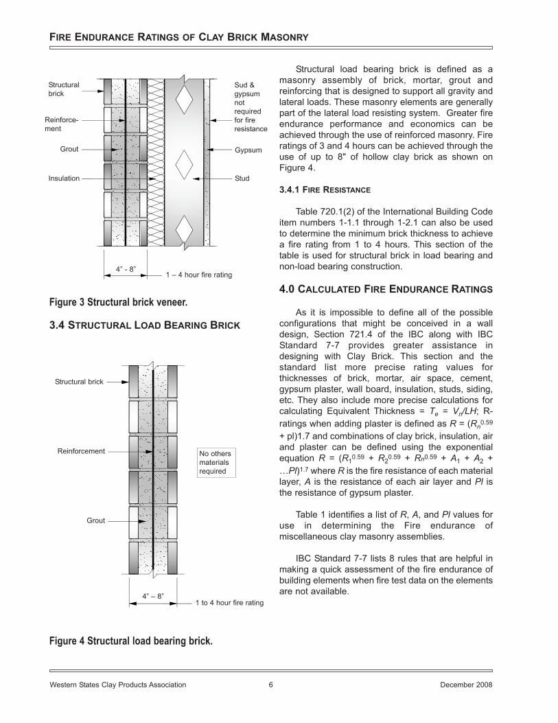
Figure 3 Structural brick veneer.
3.4 STRUCTURAL LOAD BEARING BRICK
Figure 4 Structural load bearing brick.
Structural load bearing brick is defined as amasonry assembly of brick, mortar, grout andreinforcing that is designed to support all gravity andlateral loads. These masonry elements are generallypart of the lateral load resisting system. Greater fireendurance performance and economics can beachieved through the use of reinforced masonry. Fireratings of 3 and 4 hours can be achieved through theuse of up to 8" of hollow clay brick as shown onFigure 4.
3.4.1 FIRE RESISTANCE
Table 720.1(2) of the International Building Codeitem numbers 1-1.1 through 1-2.1 can also be usedto determine the minimum brick thickness to achievea fire rating from 1 to 4 hours. This section of thetable is used for structural brick in load bearing andnon-load bearing construction.
4.0 CALCULATED FIRE ENDURANCE RATINGS
As it is impossible to define all of the possibleconfigurations that might be conceived in a walldesign, Section 721.4 of the IBC along with IBCStandard 7-7 provides greater assistance indesigning with Clay Brick. This section and thestandard list more precise rating values forthicknesses of brick, mortar, air space, cement,gypsum plaster, wall board, insulation, studs, siding,etc. They also include more precise calculations forcalculating Equivalent Thickness = Te = Vn/LH; R-ratings when adding plaster is defined as R = (Rn0.59
+ pl)1.7 and combinations of clay brick, insulation, airand plaster can be defined using the exponentialequation R = (R10.59 + R20.59 + Rn0.59 + A1 + A2 +…Pl)1.7 where R is the fire resistance of each materiallayer, A is the resistance of each air layer and Pl isthe resistance of gypsum plaster.
Table 1 identifies a list of R, A, and Pl values foruse in determining the Fire endurance ofmiscellaneous clay masonry assemblies.
IBC Standard 7-7 lists 8 rules that are helpful inmaking a quick assessment of the fire endurance ofbuilding elements when fire test data on the elementsare not available.
FIRE ENDURANCE RATINGS OF CLAY BRICK MASONRY
Western States Clay Products Association 6 December 2008
Sud &gypsumnotrequiredfor fireresistance
Gypsum
Stud
Structuralbrick
Reinforce-ment
Grout
Insulation
1 – 4 hour fire rating4” - 8”
Structural brick
Reinforcement
Grout
4” – 8”1 to 4 hour fire rating
No othersmaterialsrequired
01.Fire.qxp 11/18/2008 7:27 AM Page 6
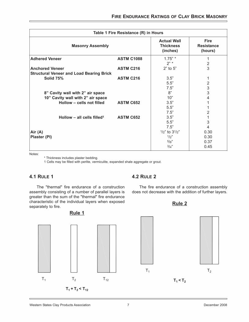
4.1 RULE 1
The "thermal" fire endurance of a constructionassembly consisting of a number of parallel layers isgreater than the sum of the "thermal" fire endurancecharacteristic of the individual layers when exposedseparately to fire.
4.2 RULE 2
The fire endurance of a construction assemblydoes not decrease with the addition of further layers.
FIRE ENDURANCE RATINGS OF CLAY BRICK MASONRY
Western States Clay Products Association 7 December 2008
Table 1 Fire Resistance (R) in Hours
Masonry AssemblyActual WallThickness(inches)
FireResistance
(hours)
Adhered Veneer ASTM C1088
Anchored Veneer ASTM C216Structural Veneer and Load Bearing Brick
Solid 75% ASTM C216
8” Cavity wall with 2” air space10” Cavity wall with 2” air space
Hollow – cells not filled ASTM C652
Hollow – all cells filled1 ASTM C652
Air (A)Plaster (Pl)
1.75” *2” *
2” to 5”
3.5”5.5”7.5”8”
10”3.5”5.5”7.5”3.5”5.5”7.5”
1/2” to 31/2”1/2”5/8”3/4”
123
12334112134
0.300.300.370.45
Notes:* Thickness includes plaster bedding.1 Cells may be filled with perlite, vermiculite, expanded shale aggregate or grout.
T1 T2 T12
T1 + T2 < T12
T1 T2
T1 < T2
Rule 1
Rule 2
01.Fire.qxp 11/18/2008 7:27 AM Page 7
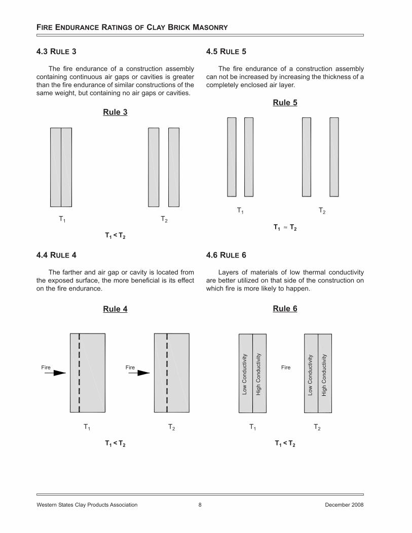
4.3 RULE 3
The fire endurance of a construction assemblycontaining continuous air gaps or cavities is greaterthan the fire endurance of similar constructions of thesame weight, but containing no air gaps or cavities.
4.4 RULE 4
The farther and air gap or cavity is located fromthe exposed surface, the more beneficial is its effecton the fire endurance.
4.5 RULE 5
The fire endurance of a construction assemblycan not be increased by increasing the thickness of acompletely enclosed air layer.
4.6 RULE 6
Layers of materials of low thermal conductivityare better utilized on that side of the construction onwhich fire is more likely to happen.
FIRE ENDURANCE RATINGS OF CLAY BRICK MASONRY
Western States Clay Products Association 8 December 2008
Rule 3
T1 T2
T1 < T2
Rule 4
T1 T2
T1 < T2
FireFire
Rule 5
T1 T2
T1 T2≈
Rule 6
T1 T2
T1 < T2
Low
Con
duct
ivity
Hig
h C
ondu
ctiv
ity
Low
Con
duct
ivity
Hig
h C
ondu
ctiv
ity
Fire
01.Fire.qxp 11/18/2008 7:27 AM Page 8
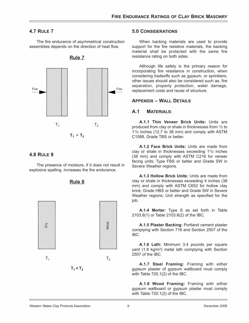
4.7 RULE 7
The fire endurance of asymmetrical constructionassemblies depends on the direction of heat flow.
4.8 RULE 8
The presence of moisture, if it does not result inexplosive spalling, increases the fire endurance.
5.0 CONSIDERATIONS
When backing materials are used to providesupport for the fire resistive materials, the backingmaterial shall be protected with the same fireresistance rating on both sides.
Although life safety is the primary reason forincorporating fire resistance in construction, whenconsidering tradeoffs such as gypsum, or sprinklers,other issues should also be considered such as, fireseparation, property protection, water damage,replacement costs and reuse of structure.
APPENDIX – WALL DETAILS
A.1 MATERIALS:
A.1.1 Thin Veneer Brick Units: Units areproduced from clay or shale in thicknesses from 1/2 to11/2 inches (12.7 to 38 mm) and comply with ASTMC1088, Grade TBS or better.
A.1.2 Face Brick Units: Units are made fromclay or shale in thicknesses exceeding 11/2 inches(38 mm) and comply with ASTM C216 for veneerfacing units; Type FBS or better and Grade SW inSevere Weather regions.
A.1.3 Hollow Brick Units: Units are made fromclay or shale in thicknesses exceeding 4 inches (38mm) and comply with ASTM C652 for hollow claybrick; Grade HBS or better and Grade SW in SevereWeather regions; Unit strength as specified for thejob.
A.1.4 Mortar: Type S as set forth in Table2103.8(1) or Table 2103.8(2) of the IBC.
A.1.5 Plaster Backing: Portland cement plastercomplying with Section 718 and Section 2507 of theIBC.
A.1.6 Lath: Minimum 3.4 pounds per squareyard (1.8 kg/m3) metal lath complying with Section2507 of the IBC.
A.1.7 Steel Framing: Framing with eithergypsum plaster of gypsum wallboard must complywith Table 720.1(2) of the IBC.
A.1.8 Wood Framing: Framing with eithergypsum wallboard or gypsum plaster must complywith Table 720.1(2) of the IBC.
FIRE ENDURANCE RATINGS OF CLAY BRICK MASONRY
Western States Clay Products Association 9 December 2008
Rule 7
FireFire
T1 T2
T1 T2≠
Rule 8
T1 T2
T1 < T2
Dry
Moi
st
01.Fire.qxp 11/18/2008 7:28 AM Page 9
A.2 WALL CONFIGURATION:
A.2.1 Adhered Veneer: Metal lath is installed incompliance with Section 2506.1 of the UBC. Wherelath is attached to steel framing, minimum 1-inch-long(25.4 mm), No. 6 drywall screws are used. Forexterior walls, a weather-resistive barrier described inSection 2510.6 of the IBC is required. The Portlandcement plaster is applied in compliance with Sections2510, 2511, and 2512 of the IBC to a minimum 3/4-inch (19.1 mm) thickness. The thin veneer units areapplied in compliance with Section 1405.9 of the IBCin running bond. For one-hour fire resistance, thetotal thickness of plaster, mortar and brick veneershall be at least 13/4 inches (45 mm). For two-hourfire resistance, the total thickness of plaster, mortarand thin brick shall be at least 2 inches (51 mm).
A.2.2 Anchored Veneer: Anchored veneer isinstalled in compliance with Section 1405.5 of theIBC for 2-to-5-inch-thick (51 to 127 mm) units andSection 1405.6 of the IBC for units up to 10 inches(254 mm) thick. Stud spacing is limited to 16 inches(406 mm) on center, and a weather-resistive barriercomplying with Section 1403.2 of the IBC is requiredon the exterior side of exterior walls. Anchored unitsmay be used for one-hour or two-hour fire-resistiveassemblies.
A.3 INSTALLATION:
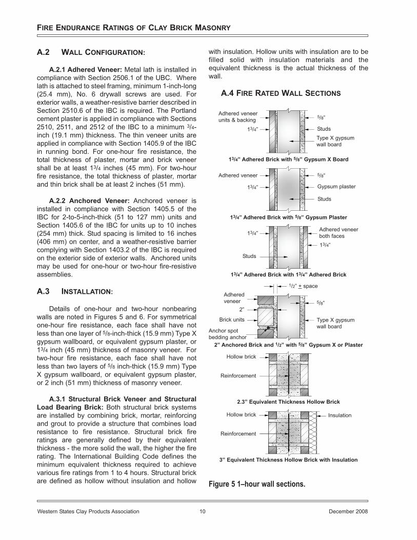
Details of one-hour and two-hour nonbearingwalls are noted in Figures 5 and 6. For symmetricalone-hour fire resistance, each face shall have notless than one layer of 5/8-inch-thick (15.9 mm) Type Xgypsum wallboard, or equivalent gypsum plaster, or13/4 inch (45 mm) thickness of masonry veneer. Fortwo-hour fire resistance, each face shall have notless than two layers of 5/8 inch-thick (15.9 mm) TypeX gypsum wallboard, or equivalent gypsum plaster,or 2 inch (51 mm) thickness of masonry veneer.
A.3.1 Structural Brick Veneer and StructuralLoad Bearing Brick: Both structural brick systemsare installed by combining brick, mortar, reinforcingand grout to provide a structure that combines loadresistance to fire resistance. Structural brick fireratings are generally defined by their equivalentthickness - the more solid the wall, the higher the firerating. The International Building Code defines theminimum equivalent thickness required to achievevarious fire ratings from 1 to 4 hours. Structural brickare defined as hollow without insulation and hollow
with insulation. Hollow units with insulation are to befilled solid with insulation materials and theequivalent thickness is the actual thickness of thewall.
A.4 FIRE RATED WALL SECTIONS
Figure 5 1–hour wall sections.
FIRE ENDURANCE RATINGS OF CLAY BRICK MASONRY
Western States Clay Products Association 10 December 2008
Adhered veneerunits & backing
5/8”
13/4” StudsType X gypsumwall board
13/4” Adhered Brick with 5/8” Gypsum X Board
Adhered veneer 5/8”
13/4”
Studs
Gypsum plaster
13/4” Adhered Brick with 5/8” Gypsum Plaster
Adhered veneerboth faces13/4”
Studs
13/4” Adhered Brick with 13/4” Adhered Brick
13/4”
Adheredveneer
2”
1/2” + space
2” Anchored Brick and 1/2” with 5/8” Gypsum X or Plaster
5/8”
Type X gypsumwall board
Brick units
Anchor spotbedding anchor
Hollow brick
Reinforcement
Hollow brick
Reinforcement
Insulation
2.3” Equivalent Thickness Hollow Brick
3” Equivalent Thickness Hollow Brick with Insulation
01.Fire.qxp 11/18/2008 7:28 AM Page 10
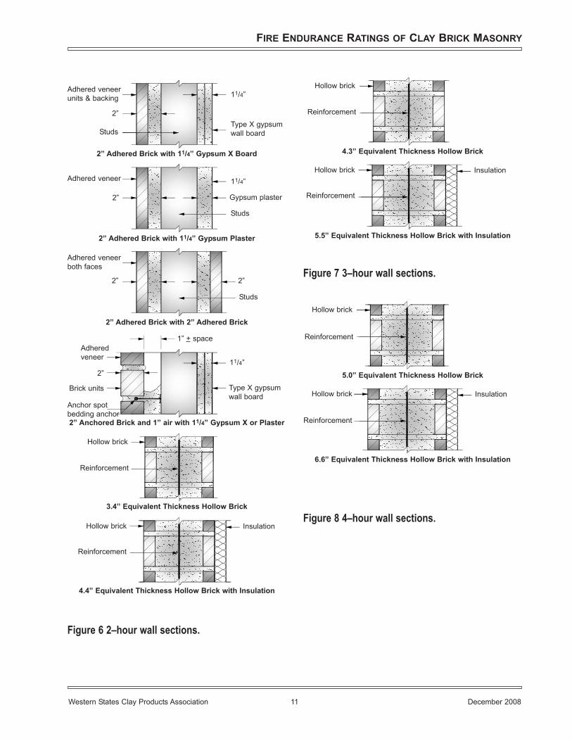
Figure 6 2–hour wall sections.
Figure 7 3–hour wall sections.
Figure 8 4–hour wall sections.
FIRE ENDURANCE RATINGS OF CLAY BRICK MASONRY
Western States Clay Products Association 11 December 2008
Adhered veneerunits & backing 11/4”
2”
StudsType X gypsumwall board
2” Adhered Brick with 11/4” Gypsum X Board
Adhered veneer
2”
Studs
Gypsum plaster
2” Adhered Brick with 11/4” Gypsum Plaster
11/4”
Adhered veneerboth faces
Studs
2” Adhered Brick with 2” Adhered Brick
2”2”
Adheredveneer
2”
1” + space
2” Anchored Brick and 1” air with 11/4” Gypsum X or Plaster
Type X gypsumwall board
Brick units
Anchor spotbedding anchor
11/4”
Hollow brick
Reinforcement
3.4” Equivalent Thickness Hollow Brick
Hollow brick
Reinforcement
Insulation
4.4” Equivalent Thickness Hollow Brick with Insulation
Hollow brick
Reinforcement
4.3” Equivalent Thickness Hollow Brick
Hollow brick
Reinforcement
Insulation
5.5” Equivalent Thickness Hollow Brick with Insulation
Hollow brick
Reinforcement
5.0” Equivalent Thickness Hollow Brick
Hollow brick
Reinforcement
Insulation
6.6” Equivalent Thickness Hollow Brick with Insulation
01.Fire.qxp 11/18/2008 7:28 AM Page 11
FIRE ENDURANCE RATINGS OF CLAY BRICK MASONRY
Western States Clay Products Association 12 December 2008
01.Fire.qxp 11/18/2008 7:28 AM Page 12
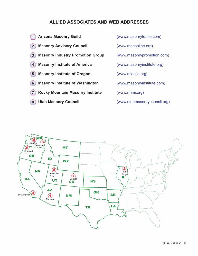
ALLIED ASSOCIATES AND WEB ADDRESSES
Arizona Masonry Guild (www.masonryforlife.com)
Masonry Advisory Council (www.maconline.org)
Masonry Industry Promotion Group (www.masonrypromotion.com)
Masonry Institute of America (www.masonryinstitute.org)
Masonry Institute of Oregon (www.mioctio.org)
Masonry Institute of Washington (www.masonryinstitute.com)
Rocky Mountain Masonry Institute (www.rmmi.org)
Utah Masonry Council (www.utahmasonrycouncil.org)
1
2
3
4
5
6
7
8
© WSCPA 2008
BackCover.qxp 11/17/2008 2:39 PM Page 1