Embed Size (px)
Citation preview
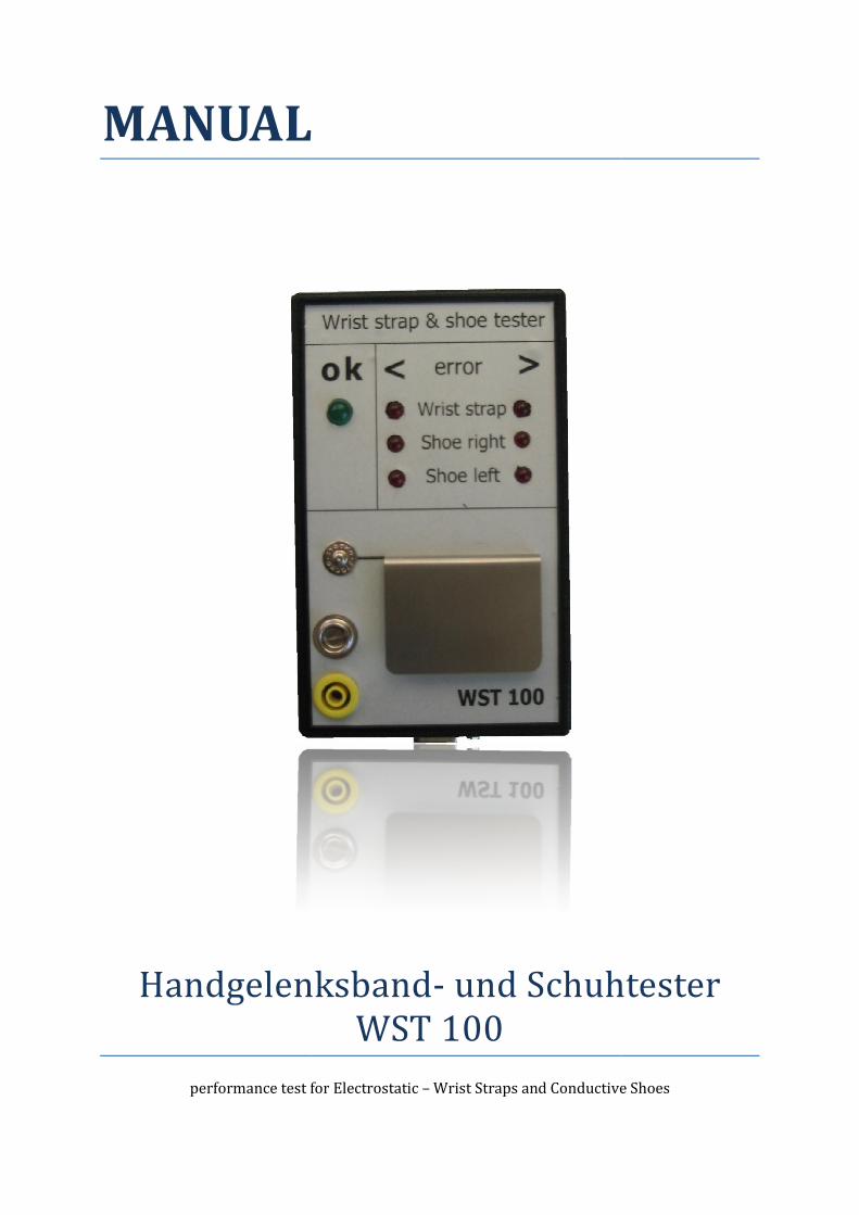
MANUAL
Handgelenksband
performance test for
MANUAL
Handgelenksband- und Schuhtester WST 100
for Electrostatic – Wrist Straps and Conductive S
und Schuhtester
Straps and Conductive Shoes
2 Handbuch WST 100
Contents
Description ........................................................................................................................................................................... 2
Specification .................................................................................................................................................................... 2
Function ............................................................................................................................................................................ 3
Wrist strap test ............................................................................................................................................................... 4
Shoe test ............................................................................................................................................................................ 4
Adjustable abilities ....................................................................................................................................................... 5
Statistisical error memory ......................................................................................................................................... 5
Limits .................................................................................................................................................................................. 5
Change Battery ............................................................................................................................................................... 5
Connection ....................................................................................................................................................................... 6
Shoe electrode connections ...................................................................................................................................... 6
Connecting a door-opener ......................................................................................................................................... 6
Scope of supply WST 100 SET .................................................................................................................................. 7
Optional accessories .................................................................................................................................................... 7
Calibration ........................................................................................................................................................................ 8
That offers great advantages: .............................................................................................................................. 8
Adjust the Limits…………………………...………………………………………………………………………………………..9
Error ..................................................................................................................................................................................... 10
Short Instruction ............................................................................................................................................................. 12
Description
The WST100 serves the function test of electrostatic wrist straps and conductive footwear.
Before you get access to ESD-secured areas the ESD precautions like wrist strap and conductive
footwear should be tested for correct functioning.
The WST-100 is a reliable and advantageous solution for this.
The appliance is portable and because of its battery power employable everywhere.
The setting of the limits and the calibration can be done by the customer himself, very simply.
A special feature is the appliance possesses a statistical error memory, in which the errors of
statistically appraised are stored.
Hand appliance in a plastic housing 150mm x 88mm complete µC controlled.
The shoe electrode for this unit is 370mm x 440mm of a plastic plate which includes 2 shoe
electrodes for the left and right shoe separately.
The display includes 7 LEDs a green LED (8mm) for o.k. and 6 red LEDs for error measage
For the additional acoustic signal a buzzer is integrated.
The appliance possesses an integrated relay 60V / 0,5A (in the shoe electrode).
With the optional plug charger and NiMH accumulators, the appliance can be run permanently.
3
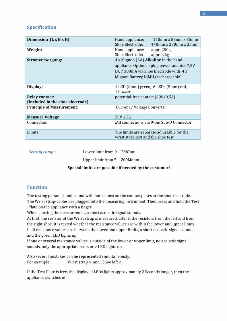
Specification
Dimension (L x B x H): Hand appliance: 150mm x 88mm x 35mm Shoe Electrode: 440mm x 370mm x 35mm
Weight: Hand appliance: appr. 250 g Shoe Electrode: appr. 2 kg
Stromversorgung: 4 x Mignon (AA) Alkaline in the hand
appliance Optional: plug power adapter 7,5V-
DC / 300mA via Shoe Electrode with 4 x
Mignon Battery NiMH (rechargeable)
Display: 1 LED (8mm) green, 6 LEDs (5mm) red, 1 buzzer
Relay contact:
(included in the shoe electrode)
potential-free contact (60V/0,5A)
Principle of Measurement: Current / Voltage Converter
Measure Voltage 20V ±5%
Connection: :All connections via 9-pin Sub-D Connector
Limits The limits are separate adjustable for the wrist strap test and the shoe test
Setting range: Lower limit from 0.... 2MOhm
Upper limit from 5.... 200Mohm
Special limits are possible if needed by the customer!
Function
The testing person should stand with both shoes on the contact plates at the shoe electrode.
The Wrist strap-cables are plugged into the measuring instrument. Then press and hold the Test
-Plate on the appliance with a finger.
When starting the measurement, a short acoustic signal sounds.
At first, the resistor of the Wrist strap is measured, after it the resistors from the left and from
the right shoe. It is tested whether the resistance values are within the lower and upper limits.
If all resistance values are between the lower and upper limits, a short acoustic signal sounds
and the green LED lights up.
If one or several resistance values is outside of the lower or upper limit, no acoustic signal
sounds, only the appropriate red < or > LED lights up.
Also several mistakes can be represented simultaneously.
For example : Wrist strap > and Shoe left <
If the Test Plate is free, the displayed LEDs lights approximately 2 Seconds longer, then the
appliance switches off.
4 Handbuch WST 100
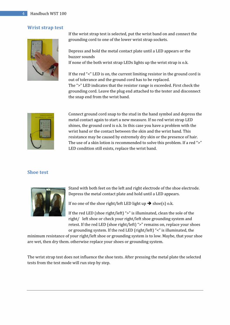
Wrist strap test
If the wrist strap test is selected, put the wrist band on and connect the
grounding cord to one of the lower wrist strap sockets.
Depress and hold the metal contact plate until a LED appears or the
buzzer sounds
If none of the both wrist strap LEDs lights up the wrist strap is o.k.
If the red “<” LED is on, the current limiting resistor in the ground cord is
out of tolerance and the ground cord has to be replaced.
The “>” LED indicates that the resistor range is exceeded. First check the
grounding cord. Leave the plug end attached to the tester and disconnect
the snap end from the wrist band.
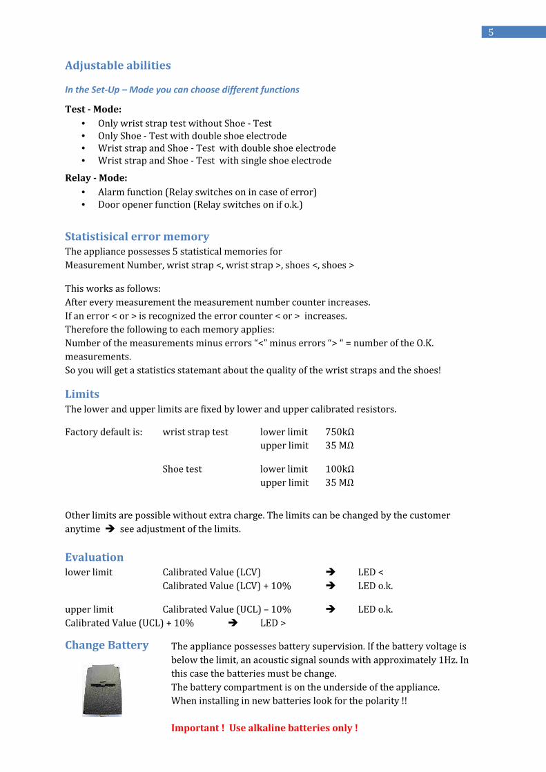
Connect ground cord snap to the stud in the hand symbol and depress the
metal contact again to start a new measure. If no red wrist strap LED
shines, the ground cord is o.k. In this case you have a problem with the
wrist band or the contact between the skin and the wrist band. This
resistance may be caused by extremely dry skin or the presence of hair.
The use of a skin lotion is recommended to solve this problem. If a red “>”
LED condition still exists, replace the wrist band.
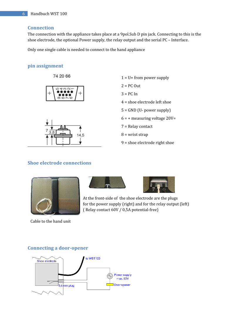
Shoe test
Stand with both feet on the left and right electrode of the shoe electrode.
Depress the metal contact plate and hold until a LED appears.
If no one of the shoe right/left LED light up shoe(s) o.k.
If the red LED (shoe right/left) “>” is illuminated, clean the sole of the
right/ left shoe or check your right/left shoe grounding system and
retest. If the red LED (shoe right/left) “>” remains on, replace your shoes
or grounding system. If the red LED (right/left) “<” is illuminated, the
minimum resistance of your right/left shoe or grounding system is to low. Maybe, that your shoe
are wet, then dry them. otherwise replace your shoes or grounding system.
The wrist strap test does not influence the shoe tests. After pressing the metal plate the selected
tests from the test mode will run step by step.
5
Adjustable abilities
In the Set-Up – Mode you can choose different functions
Test - Mode:
• Only wrist strap test without Shoe - Test
• Only Shoe - Test with double shoe electrode
• Wrist strap and Shoe - Test with double shoe electrode
• Wrist strap and Shoe - Test with single shoe electrode
Relay - Mode:
• Alarm function (Relay switches on in case of error)
• Door opener function (Relay switches on if o.k.)
Statistisical error memory
The appliance possesses 5 statistical memories for
Measurement Number, wrist strap <, wrist strap >, shoes <, shoes >
This works as follows:
After every measurement the measurement number counter increases.
If an error < or > is recognized the error counter < or > increases.
Therefore the following to each memory applies:
Number of the measurements minus errors “<” minus errors “> “ = number of the O.K.
measurements.
So you will get a statistics statemant about the quality of the wrist straps and the shoes!
Limits
The lower and upper limits are fixed by lower and upper calibrated resistors.
Factory default is: wrist strap test lower limit 750kΩ
upper limit 35 MΩ
Shoe test lower limit 100kΩ
upper limit 35 MΩ
Other limits are possible without extra charge. The limits can be changed by the customer
anytime see adjustment of the limits.
Evaluation
lower limit Calibrated Value (LCV) LED <
Calibrated Value (LCV) + 10% LED o.k.
upper limit Calibrated Value (UCL) – 10% LED o.k.
Calibrated Value (UCL) + 10% LED >
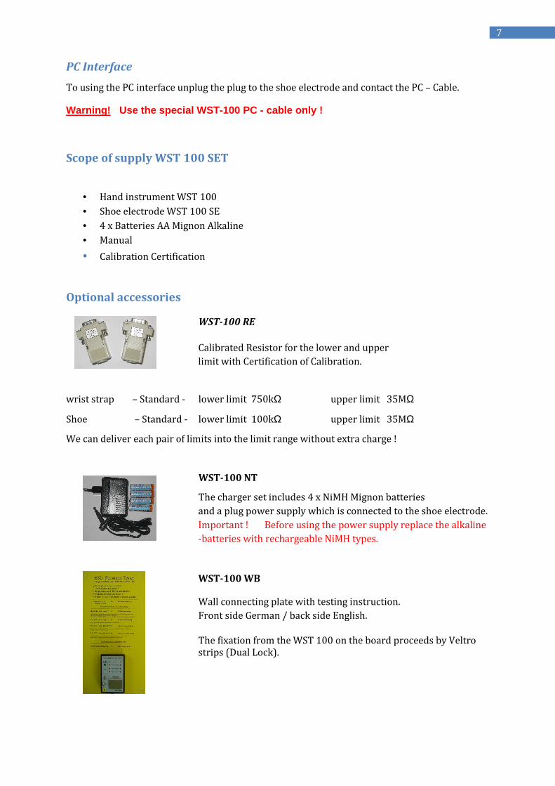
Change Battery
The appliance possesses battery supervision. If the battery voltage is
below the limit, an acoustic signal sounds with approximately 1Hz. In
this case the batteries must be change.
The battery compartment is on the underside of the appliance.
When installing in new batteries look for the polarity !!
Important ! Use alkaline batteries only !
6 Handbuch WST 100
Connection
The connection with the appliance takes place at a 9pol.Sub D pin jack. Connecting to this is the
shoe electrode, the optional Power supply, the relay output and the serial PC – Interface.
Only one single cable is needed to connect to the hand appliance
pin assignment
Shoe electrode connections
At the front-side of the shoe electrode are the plugs
for the power supply (right) and for the relay output (left)
( Relay contact 60V / 0,5A potential-free)
↑
Cable to the hand unit
Connecting a door-opener
1 = U+ from power supply
2 = PC Out
3 = PC In
4 = shoe electrode left shoe
5 = GND (U- power supply)
6 = + measuring voltage 20V=
7 = Relay contact
8 = wrist strap
9 = shoe electrode right shoe
7
PC Interface
To using the PC interface unplug the plug to the shoe electrode and contact the PC – Cable.
Warning! Use the special WST-100 PC - cable only !
Scope of supply WST 100 SET
• Hand instrument WST 100
• Shoe electrode WST 100 SE
• 4 x Batteries AA Mignon Alkaline
• Manual
• Calibration Certification
Optional accessories
WST-100 RE
Calibrated Resistor for the lower and upper
limit with Certification of Calibration.
wrist strap – Standard - lower limit 750kΩ upper limit 35MΩ
Shoe – Standard - lower limit 100kΩ upper limit 35MΩ
We can deliver each pair of limits into the limit range without extra charge !
WST-100 NT
The charger set includes 4 x NiMH Mignon batteries
and a plug power supply which is connected to the shoe electrode.
Important ! Before using the power supply replace the alkaline
-batteries with rechargeable NiMH types.
WST-100 WB
Wall connecting plate with testing instruction.
Front side German / back side English.
The fixation from the WST 100 on the board proceeds by Veltro strips (Dual Lock).
8 Handbuch WST 100
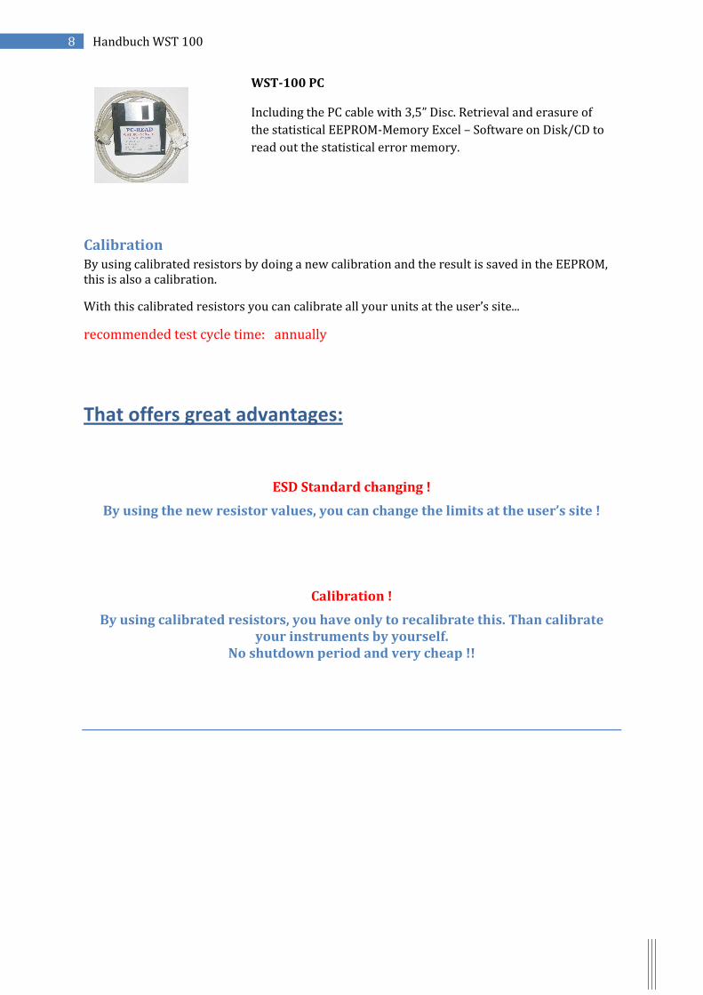
WST-100 PC
Including the PC cable with 3,5” Disc. Retrieval and erasure of
the statistical EEPROM-Memory Excel – Software on Disk/CD to
read out the statistical error memory.
Calibration
By using calibrated resistors by doing a new calibration and the result is saved in the EEPROM, this is also a calibration.
With this calibrated resistors you can calibrate all your units at the user’s site...
recommended test cycle time: annually
That offers great advantages:
ESD Standard changing !
By using the new resistor values, you can change the limits at the user’s site !
Calibration !
By using calibrated resistors, you have only to recalibrate this. Than calibrate your instruments by yourself.
No shutdown period and very cheap !!
9
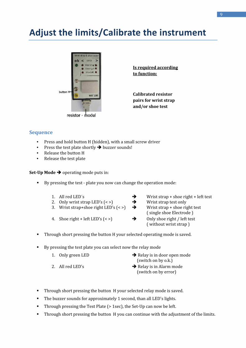
Adjust the limits/Calibrate the instrument
Sequence
• Press and hold button H (hidden), with a small screw driver
• Press the test plate shortly buzzer sounds!
• Release the button H
• Release the test plate
Set-Up Mode operating mode puts in:
By pressing the test - plate you now can change the operation mode:
1. All red LED´s Wrist strap + shoe right + left test 2. Only wrist strap LED’s (< >) Wrist strap test only 3. Wrist strap+shoe right LED’s (< >) Wrist strap + shoe right test ( single shoe Electrode )
4. Shoe right + left LED’s (< >) Only shoe right / left test ( without wrist strap )
Through short pressing the button H your selected operating mode is saved.
By pressing the test plate you can select now the relay mode
1. Only green LED Relay is in door open mode (switch on by o.k.)
2. All red LED’s Relay is in Alarm mode (switch on by error)
Through short pressing the button H your selected relay mode is saved.
The buzzer sounds for approximately 1 second, than all LED's lights.
Through pressing the Test Plate (> 1sec), the Set-Up can now be left.
Through short pressing the button H you can continue with the adjustment of the limits.
Is required according
to function:
Calibrated resistor
pairs for wrist strap
and/or shoe test
10 Handbuch WST 100
Set-Up Mode Read Calibration Resistors :
The LED wrist strap < lights up.
(only if wrist strap is tested).
Connect calibration resistor module for wrist strap limits,
Press briefly button H.
If value is O.K., the green LED lights up (+ buzzer for 1 seconds),
afterwards the LED wrist strap > lights up.
Press briefly button “H“.
If the value is O.K., the green LED lights up (+ buzzer) for 1 second
afterwards LEDs shoe right < and shoe left < lights up. (only if Mode „Only Wrist strap“ is not selected)
Connect the calibration resistor - module for shoe limits
Ppress briefly button H.
If value is O.K., the green LED lights (+ buzzers) for 1 seconds,
afterwards the LED`s shoe right/left > lights.
Press briefly button H.
If value is O.K., the green LED lights.
The new limits are saved
By pressing the test - plate the WST-100 switchs off
Limit ranges :
lower limit : 0 . . . . . 2 MΩ
upper limit : 5 . . . . . 200 MΩ
Special ranges are available!
Error
If a connected calibration resistor is out of these ranges, all 6 red LEDs flash..
5 x Error Calibration Value
After that the unit switches off.
Important! In this case you must repeat the complete Set – Up !!!
11
Calibration
Since the values are written directly with the adjustment into the EEPROM, the adjustment of
the limits with calibrated resistors is also simultaneously the calibration of the appliance.
In order to return to the normes, the calibrated resistors can be calibrated by the manufacturer
annually.
With these calibrated resistors, all appliances of the customer can then be calibrated again.
Suggested calibration cycles: annual
Calibrated Resistor Module RE-100
A calibrated resistor modulo consists of a 9-pin Sub-D Plug with the calibrated resistors for the
lower and upper limits the following standard - modules are offered:
A lower limit 100kΩ upper limit 35MΩ
B lower limit 750kΩ upper limit 35MΩ
Every desired resistance combination within the limit ranges can be delivered without extra
charge!
12 Handbuch WST 100
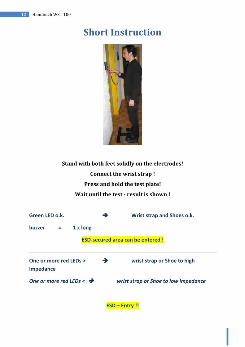
Short Instruction
Stand with both feet solidly on the electrodes!
Connect the wrist strap !
Press and hold the test plate!
Wait until the test - result is shown !
Green LED o.k. Wrist strap and Shoes o.k.
buzzer = 1 x long
ESD-secured area can be entered !
One or more red LEDs > wrist strap or Shoe to high
impedance
One or more red LEDs < wrist strap or Shoe to low impedance
ESD – Entry !!