Embed Size (px)
Citation preview

X-ray Optics-Free FEL Oscillator
There is a need for an X-ray FEL oscillator to further the quality of X-ray beams. While SASE FELs demonstrated the capability of providing very high gain and short pulses of radiation and scalability to the X-ray range, the spectra of SASE FELs remains rather wide (~0.5%-1%) compared with typical short wavelengths FEL-oscillators (0.01% - 0.0003%). Absence of good optics in VUV and X-ray ranges makes traditional oscillator schemes with very high average and peak spectral brightness either very complex or, strictly speaking, impossible. In this paper, we describe the concept of X-ray optics-free FEL oscillator, discuss its feasibility, and present some initial results and plan for detailed computer simulations.
*Originally presented at ICFA workshop, July 1-6, 2002, Chia Laguna, Sardinia, Italy Additional materials from the FEL prize talk at FEL’05 Conference, 2005, Stanford, CA, USA and FEL’07 conference at Novosibirsk, Russia
Old idea* X-OFFELO
V.N. Litvinenko, FLS 2010, SLAC, March 4, 2010
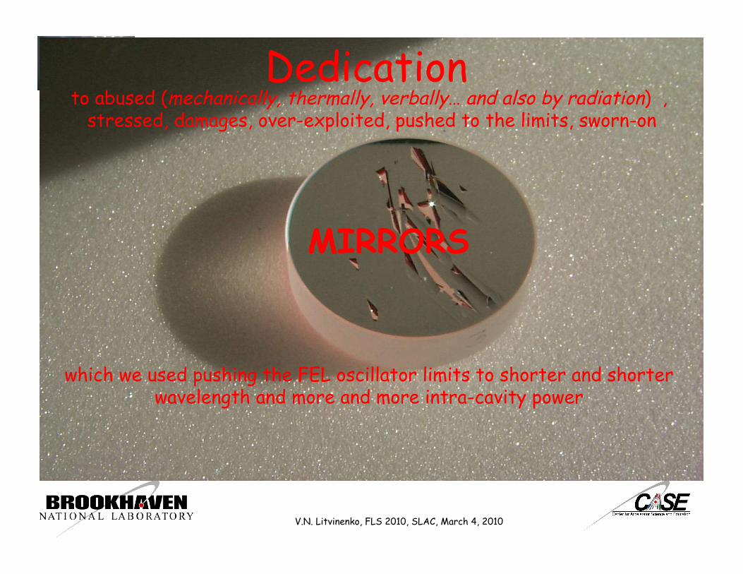
Dedication to abused (mechanically, thermally, verbally… and also by radiation) ,
stressed, damages, over-exploited, pushed to the limits, sworn-on
MIRRORS
which we used pushing the FEL oscillator limits to shorter and shorter wavelength and more and more intra-cavity power
V.N. Litvinenko, FLS 2010, SLAC, March 4, 2010
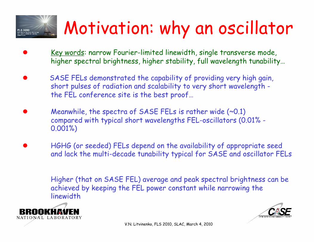
Motivation: why an oscillator Key words: narrow Fourier-limited linewidth, single transverse mode,
higher spectral brightness, higher stability, full wavelength tunability…
SASE FELs demonstrated the capability of providing very high gain, short pulses of radiation and scalability to very short wavelength - the FEL conference site is the best proof…
Meanwhile, the spectra of SASE FELs is rather wide (~0.1) compared with typical short wavelengths FEL-oscillators (0.01% - 0.001%)
HGHG (or seeded) FELs depend on the availability of appropriate seed and lack the multi-decade tunability typical for SASE and oscillator FELs
Higher (that on SASE FEL) average and peak spectral brightness can be achieved by keeping the FEL power constant while narrowing the linewidth
V.N. Litvinenko, FLS 2010, SLAC, March 4, 2010
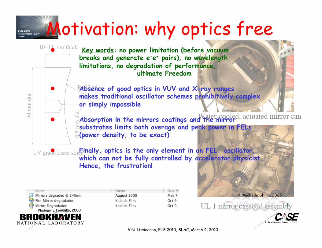
Motivation: why optics free Key words: no power limitation (before vacuum
breaks and generate e-e+ pairs), no wavelength limitations, no degradation of performance, ultimate Freedom
Absence of good optics in VUV and X-ray ranges makes traditional oscillator schemes prohibitively complex or simply impossible
Absorption in the mirrors coatings and the mirror substrates limits both average and peak power in FELs (power density, to be exact)
Finally, optics is the only element in an FEL oscillator, which can not be fully controlled by accelerator physicist. Hence, the frustration!
® Michelle Shinn, 2005
Vladimir Litvinenko, 2000
V.N. Litvinenko, FLS 2010, SLAC, March 4, 2010

0
0.2
0.4
0.6
0.8
1
208 212 216 220 224
Lasing Line at 218.65 nmRMS linewidth: 0.0157 nm (including resolution)
Inte
nsi
ty,
no
rmal
ized
! , nm
"!/!=7.18#10$ 5FWHM=1.4*10
- 4
Lasing Lines and Spikes
©OK-4 FEL
OK-4 - 0.0072% RMS TESLA - 0.51% RMS LCLS @ 1.5 Å 0.015 nm @ 218 nm 0.55 nm @ 108 nm - 0.37% RMS Fourier limited
V.N. Litvinenko, FLS 2010, SLAC, March 4, 2010
©TESLA FEL
Courtesy of J.Walsh Courtesy of J. Roβbach

Oscillator Full longitudinal coherence FEL pulse is much shorter than e-beam
0
20
40
60
80
100
120
-30 -20 -10 0 10 20 30
Inte
nsity
, a.u
. Slic
e #4
τ, psec
Fit: I(τ) = a0 exp(-τ2/2σ02)+ a1 exp(-τ2/2σ
12);
a0=67; σ
0=1.91 psec; a
1=36; σ
0=9.66 psec;
e--beam
FEL lght
10 msec
0.5 nsec
V.N. Litvinenko, FLS 2010, SLAC, March 4, 2010
100 fsec e-bunch in an oscillator
3 fsec Fourier limited FEL pulses will be generated by
© TESLA FEL ©LCLS

Oscillator
G(ω) Pin(ω) Pout(ω) =G(ω) . Pin(ω)
Amplifier Detailed analysis of the lasing linewidth of saturated oscillator is in:
Pspont(ω)
Current, I, A ~ 100 A
Wavelength, Å ~ 1
Δω/ω ~ 10-3
Ko ~ 1.2
δω/ω Correlations length
~ 3 10-8
~ 3 mm !!!
K(ω)= G(ω) κ(ω,P)
€
K(ω) ≈K(ωo) ⋅ 1-ω -ωo( )2
Δω 2
€
Pout (ω) ≈ Pout (ωo) ⋅ 1-ω -ωo( )2
δω 2
κ(ω,P) Feedback
€
κ ωo,P = 0( ) ⋅G ωo( ) >1
V.N. Litvinenko, FLS 2010, SLAC, March 4, 2010
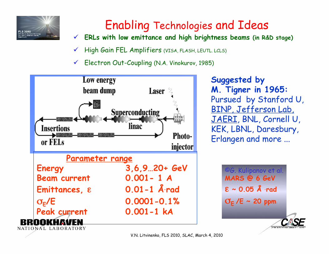
Suggested by M. Tigner in 1965: Pursued by Stanford U, BINP, Jefferson Lab, JAERI, BNL, Cornell U, KEK, LBNL, Daresbury, Erlangen and more ...
Parameter range Energy 3,6,9…20+ GeV Beam current 0.001- 1 A Emittances, ε 0.01-1 Å.rad σE/E 0.0001-0.1% Peak current 0.001-1 kA
©G. Kulipanov et al. MARS @ 6 GeV ε ~ 0.05 Å .rad
σE /E ~ 20 ppm
V.N. Litvinenko, FLS 2010, SLAC, March 4, 2010
Enabling Technologies and Ideas ERLs with low emittance and high brightness beams (in R&D stage)
High Gain FEL Amplifiers (VISA, FLASH, LEUTL. LCLS)
Electron Out-Coupling (N.A. Vinokurov, 1985)
9
STAR
Polarized e-gun
Beam dump
10 to 20 GeV e x 325 GeV p – 130 GeV/u Au eRHIC
9
2 x 200 m SRF linac 4 (5) GeV per pass
5 (4) passes
4 to 5 vertically separated
recirculating passes
Possibility of 30 GeV low current
operation
5 mm
5 mm
5 mm
5 mm
20 GeV e-beam
16 GeV e-beam
12 GeV e-beam
8 GeV e-beam
Com
mon
vac
uum
cha
mbe
r
Gap 5 mm total 0.3 T for 30 GeV
eRHIC detector
V.N. Litvinenko, EICC meeting, Stony Brook, NY, January 11, 2010
Enabling Technologies and Ideas
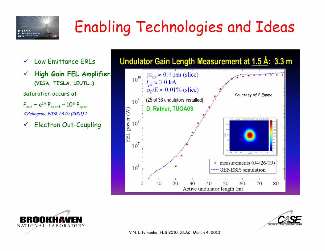
Low Emittance ERLs
High Gain FEL Amplifiers (VISA, TESLA, LEUTL…)
saturation occurs at
Pout ~ e14 Pspont ~ 106 Pspon
C.Pellegrini, NIM A475 (2001) 1
Electron Out-Coupling
V.N. Litvinenko, FLS 2010, SLAC, March 4, 2010
Courtesy of P.Emma
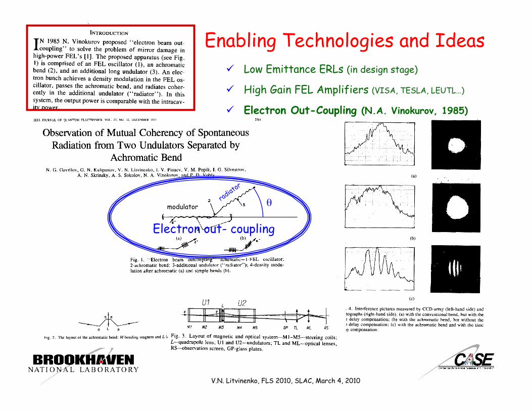
θ
Electron out- coupling
modulator
V.N. Litvinenko, FLS 2010, SLAC, March 4, 2010
Enabling Technologies and Ideas Low Emittance ERLs (in design stage)
High Gain FEL Amplifiers (VISA, TESLA, LEUTL…)
Electron Out-Coupling (N.A. Vinokurov, 1985)

OFFELO #1 High Gain Ring FEL oscillator
Suggested by N.A. Vinokurov in 1995 , Nucl. Instr. and Meth. A 375 (1996) 264 Multiple wigglers separated by second order achromatic bends
V.N. Litvinenko, FLS 2010, SLAC, March 4, 2010
1.5 Å Ring FEL

Ring FEL - low energy • For a low energy beams (and rather long
wavelength) it is conceivable to modulate the beam using a short wiggler, turn it around, and to amplify the modulation and the resulting optical power in a high gain amplifier
High Gain FEL
Fresh e-beam
Modulated e-beam Photons
Modulator Wiggler
Used e-beam
V.N. Litvinenko, FLS 2010, SLAC, March 4, 2010
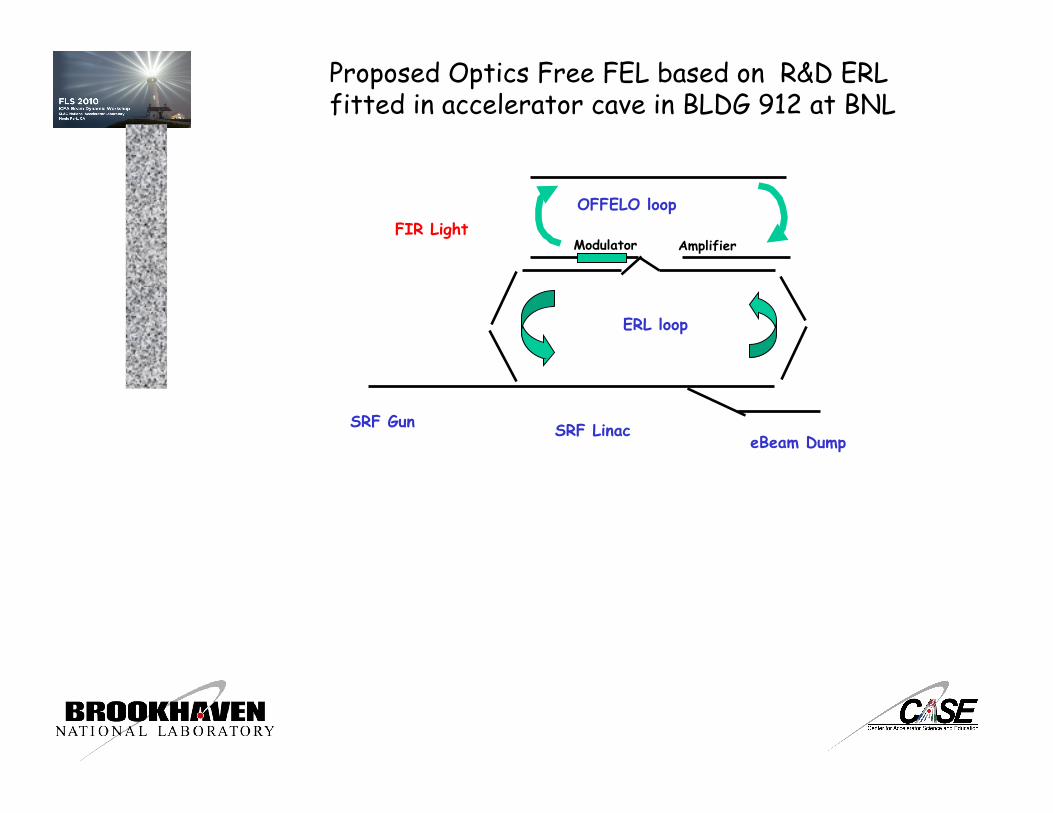
Proposed Optics Free FEL based on R&D ERL fitted in accelerator cave in BLDG 912 at BNL
ERL loop
SRF Gun eBeam Dump
SRF Linac
OFFELO loop FIR Light
Modulator Amplifier
19.8 m
Laser Light
eBeam
eBeam
V.N. Litvinenko, FLS 2010, SLAC, March 4, 2010
0.0 2. 4. 6. 8. 10. 12. 14. 16.
s (m)
! E/ p 0c = 0 .
Table name = TW
Isochronous bend 20 Mev
Win32 version 8.51/15 04/07/07 14.43.29
0.0
5.
10.
15.
20.
25.
30.
"(m
)
-30.
-25.
-20.
-15.
-10.
-5.
0.0
5.
10.
Dx
(m),
dD
x/d!
(m)
" x " y Dx Dx’
Optics functions in isochronous loop for OFFELO
(PARMELA simulation)
Charge per bunch, nC 0.7 1.4 5
Numbers of passes 1 1 1
Energy maximum/injection, MeV 20/2.5 20/2.5 20/3.0
Bunch rep-rate, MHz 700 350 9.383
Average current, mA 500 500 50
Injected/ejected beam power, MW 1.0 1.0 0.15
Normalized emittances ex/ey, mm*mrad 1.4/1.4 2.2/2.3 4.8/5.3
Energy spread, dE/E 3.5x10⁻³ 5x10⁻³ 1x10⁻²
Bunch length, ps 18 21 31

FEL simulation results for OFFELO at BNL R&D ERL GENISIS simulations
5 cm undulators period and 0.7 nC electron beam at rep. frequency 9.38 MHz the GENESIS simulation gives: wavelength 29 microns, peak power 2 MW and average power 400 W. For full current mode operation rep. rate 703.75 MHz we obtain 30 kW far infrared in CW mode.
Spectrum
Peak power reaches 2 MW
V.N. Litvinenko, FLS 2010, SLAC, March 4, 2010
0
1 105
2 105
3 105
4 105
5 105
0 10 20 30 40 50
Power, W
Pow
er,
W
Pass
Close to the Fourier limited spectrum
0
10
20
30
40
50
28 28.5 29 29.5 30
Intensity
Inte
nsi
ty, a.
u.
!, µm0
0.5
1
1.5
2
2.5
0 5 10 15 20 25 30
Peak power, MW
Optical pulse
The central wavelength 29μm and FWHM 0.35%.

High Gain Ring FEL oscillator - cont.
Plus 2nd order aberrations
Three-bend isochronous achromat (positive, negative, positive bends)
V.N. Litvinenko, FLS 2010, SLAC, March 4, 2010

Ultimate Ring FEL • Turning around strongly modulated beam
high energy beam does not work
High Gain FEL
Fresh e-beam
Used e-beam
Photons
Photons
Feed-back Wiggler
Used e-beam
V.N. Litvinenko, FLS 2010, SLAC, March 4, 2010
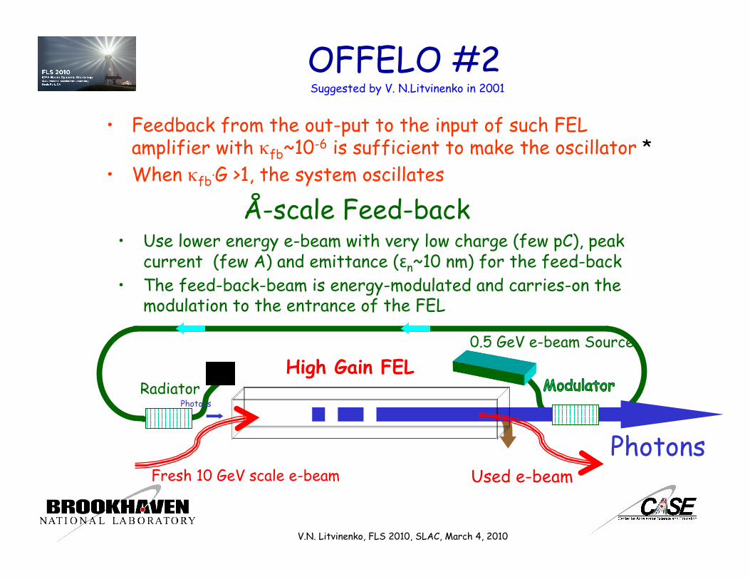
OFFELO #2 Suggested by V. N.Litvinenko in 2001
• Feedback from the out-put to the input of such FEL amplifier with κfb~10-6 is sufficient to make the oscillator *
• When κfb.G >1, the system oscillates
V.N. Litvinenko, FLS 2010, SLAC, March 4, 2010
Å-scale Feed-back • Use lower energy e-beam with very low charge (few pC), peak
current (few A) and emittance (εn~10 nm) for the feed-back • The feed-back-beam is energy-modulated and carries-on the
modulation to the entrance of the FEL
High Gain FEL
Fresh 10 GeV scale e-beam Used e-beam Photons
Radiator
0.5 GeV e-beam Source
Photons

Alternative Feed-back scheme • Use beam with necessary energy for effective energy
modulation (i.e. use of a typical wiggler) • Decelerate the feed-back beam to much lower energy (let’s
say ~100 MeV) where synchrotron radiation is mitigated • Turn the beam around, accelerate it to radiate in the
radiator, decelerate it and dump it
High Gain FEL
Fresh e-beam Used e-beam Radiator Modulator
source
Low energy pass
ERL ERL dump Photons
V.N. Litvinenko, FLS 2010, SLAC, March 4, 2010
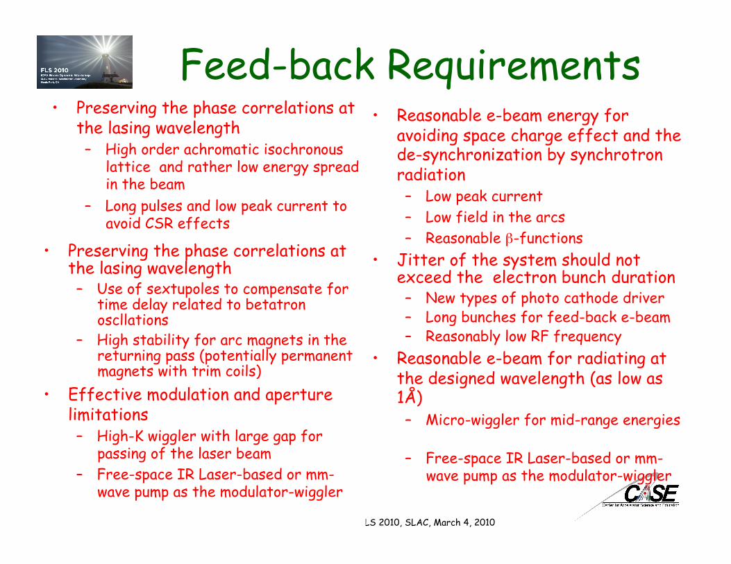
• Preserving the phase correlations at the lasing wavelength – High order achromatic isochronous
lattice and rather low energy spread in the beam
– Long pulses and low peak current to avoid CSR effects
• Reasonable e-beam energy for avoiding space charge effect and the de-synchronization by synchrotron radiation – Low peak current – Low field in the arcs – Reasonable β-functions
Feed-back Requirements
V.N. Litvinenko, FLS 2010, SLAC, March 4, 2010
• Preserving the phase correlations at the lasing wavelength – Use of sextupoles to compensate for
time delay related to betatron oscllations
– High stability for arc magnets in the returning pass (potentially permanent magnets with trim coils)
• Jitter of the system should not exceed the electron bunch duration – New types of photo cathode driver – Long bunches for feed-back e-beam – Reasonably low RF frequency
• Effective modulation and aperture limitations – High-K wiggler with large gap for
passing of the laser beam – Free-space IR Laser-based or mm-
wave pump as the modulator-wiggler
• Reasonable e-beam for radiating at the designed wavelength (as low as 1Å) – Micro-wiggler for mid-range energies
– Free-space IR Laser-based or mm-wave pump as the modulator-wiggler
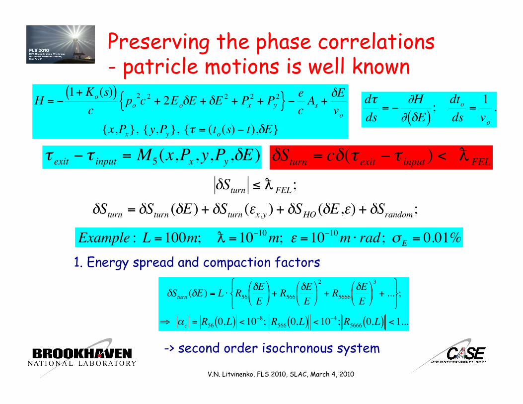
Preserving the phase correlations - patricle motions is well known
€
dτds
= −∂H∂ δE( )
; dtods
=1vo
.
€
H = −1+ Ko(s)( )
cpo
2c 2 + 2EoδE + δE 2 + Px2 + Py
2{ }− ec As +δEvo
{x,Px}, {y,Py}, {τ = (to(s) − t),δE}
€
τ exit − τ input = M5(x,Px,y,Py,δE)
€
δSturn = cδ(τ exit − τ input ) < FEL
V.N. Litvinenko, FLS 2010, SLAC, March 4, 2010
€
δSturn ≤ FEL;δSturn = δSturn (δE) + δSturn (εx,y ) + δSHO (δE,ε) + δSrandom;
€
Example : L =100m; =10−10m; ε =10−10m ⋅ rad; σE = 0.01%1. Energy spread and compaction factors
€
δSturn (δE) = L ⋅ R56δEE
+ R566
δEE
2
+ R5666δEE
3
+ ...
;
⇒ αc = R56 0,L( ) <10−8; R566 0,L( ) <10−4; R5666 0,L( ) <1...
-> second order isochronous system

δSturn(εx ,y ) = η ′ η [ ]0 1−1 0
x′ x
+ f (ε ) + O(ε 2 )
η < 10−5mβ[m] ; ′ η < 10−5 β[m];
2. Emittance effects
Solution is a second order achromat (N cell with phase advance 2πM, M/N is not integer, etc.) with second order geometrical aberration cancellation
Linear term: comes from symplectic conditions
€
MTSM = S;
S =
σ 0 00 σ 00 0 σ
; σ =0 1−1 0
It is not a problem to make the turn achromatic with η=0 and η’=0 It is a bit more complicated to make the condition energy independent.
An elegant solution - sextupoles combined with quadrupoles with K2=K1/2η:
€
′ ′ x = −K1x + K2 ⋅ x +η ⋅δ( )2 − y 2( )
1+ δ= −K1 ⋅ x + O(x 2,y 2)
′ ′ y =K1y + 2K2y ⋅ η ⋅ δ + x( )
1+ δ= K1 ⋅ y + O(xy)
€
O(x 2,y 2,xy,η2 )0
L
∫ ⇒ 0
V.N. Litvinenko, FLS 2010, SLAC, March 4, 2010
€
FEL ~ 1Å
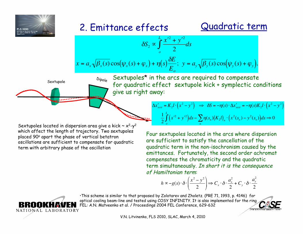
2. Emittance effects
€
δS2 ∝′ x 2 + ′ y 2
2o
L
∫ ds
x = ax βx (s) cos ψx (s) +ϕx( ) +η s( )δEEo
; y = ay βy (s) cos ψy (s) +ϕy( ).
Quadratic term
Sextupole Dipole
Sextupoles located in dispersion area give a kick ~ x2-y2 which affect the length of trajectory. Two sextupoles placed 90o apart the phase of vertical betatron oscillations are sufficient to compensate for quadratic term with arbitrary phase of the oscillation
V.N. Litvinenko, FLS 2010, SLAC, March 4, 2010
Sextupoles* in the arcs are required to compensate for quadratic effect sextupole kick + symplectic conditions give us right away:
• This scheme is similar to that proposed by Zolotarev and Zholetz. (PRE 71, 1993, p. 4146) for optical cooling beam-line and tested using COSY INFINITY. It is also implemented for the ring FEL: A.N. Matveenko et al. / Proceedings 2004 FEL Conference, 629-632
€
Δ ′ x sext = K2l ⋅ x 2 − y 2( ) ⇒ δS = −η(s) ⋅ Δ ′ x sext = −η(s)K2l ⋅ x 2 − y 2( )12
′ x 2 + ′ y 2( )dso
L
∫ − η(sn ) K2l( )n ⋅ x 2(sn ) − y 2(sn )( )dsn∑ ⇒ 0
Four sextupoles located in the arcs where dispersion are sufficient to satisfy the cancellation of the quadratic term in the non-isochronism caused by the emittances. Fortunately, the second order achromat compensates the chromaticity and the quadratic term simultaneously. In short it is the consequence of Hamiltonian term:
€
h∝−g(s) ⋅ δ ⋅ x 2 − y 2
2
⇒ Cx ⋅ δ ⋅
ax2
2+ Cy ⋅ δ ⋅
ay2
2
Emittance effects 1. The fact that e-beam passes only once (in contrast with storage
rings) allows to use very strong nonlinear elements in the system
2. The compensation required only at the exit of the turn, i.e. there is no parasitic density modulation anywhere in the arc, hence no coherent radiation and wake-fields. This is very positive effect of smearing caused by the non-zero emittances
V.N. Litvinenko, FLS 2010, SLAC, March 4, 2010
Single particle effects - conclusion • OFFELO is feasible • Higher order terms must be taken into account (using exact
analytical expressions or symplectic high order integrators) to ensure the result
• Stability of power supplies and the quality of the magnets may require special R&D

Random effects
• Quantum fluctuations of synchrotron radiation
• Ripples in the power supplies • Intra-beam scattering • Wake-fields • CSR • Others
V.N. Litvinenko, FLS 2010, SLAC, March 4, 2010

Synchrotron Radiation • Energy of the radiated quanta
• Number of radiated quanta per turn
• Radiation is random -> the path time will vary • The lattice should be designed to minimize the random effects
εc[keV ] = 0.665 ⋅B[T] ⋅Ee2[GeV ]
Nc ≅ 2παγ ≅ 89.7 ⋅E[GeV]
V.N. Litvinenko, FLS 2010, SLAC, March 4, 2010
€
δSrand( )2≈ Nc
εcEe
2
R256(s,L)
R56(s,L) is the longtudinal dispersion from azimuth s to L
⇒ R256(s,L) <
2Nc
Ee
εc
€
R256(s,L) <2.25 ⋅10−5m ⋅ Ee−3 / 2[GeV ] ⋅ B−1[T]
It looks as the toughest requirement for the scheme to be feasible
€
FEL ~ 1Å
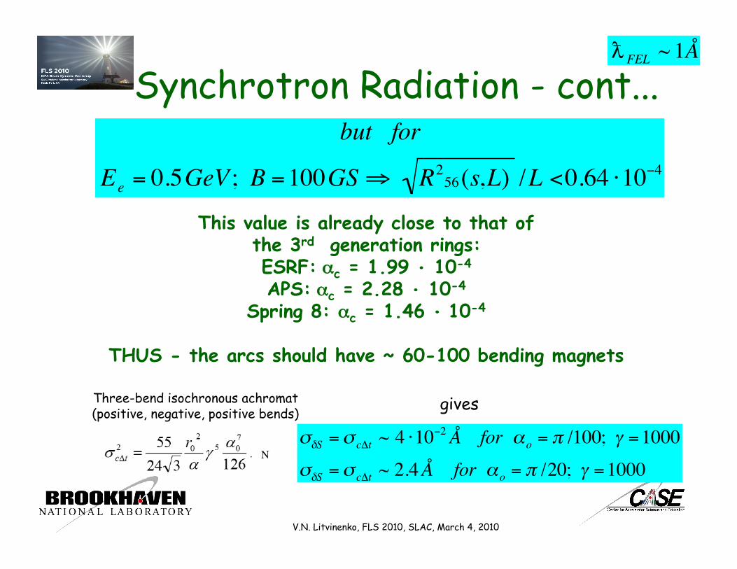
Synchrotron Radiation - cont...
€
but for
Ee = 0.5GeV ; B =100GS⇒ R256(s,L) /L <0.64 ⋅10−4
This value is already close to that of the 3rd generation rings: ESRF: αc = 1.99 • 10-4 APS: αc = 2.28 • 10-4
Spring 8: αc = 1.46 • 10-4
THUS - the arcs should have ~ 60-100 bending magnets
Three-bend isochronous achromat (positive, negative, positive bends) gives
€
σδS =σ cΔt ~ 4 ⋅10−2Å for αo = π /100; γ =1000σδS =σ cΔt ~ 2.4Å for αo = π /20; γ =1000
N
V.N. Litvinenko, FLS 2010, SLAC, March 4, 2010
€
FEL ~ 1Å

Feed-Back radiation • Energy Modulation of the feed-back e-beam should not be a problem - the FEL power is
high and a few wiggler periods will do the job • For efficient feed-back the spectral intensity of the coherent feed-back radiation
should be significantly larger than the spontaneous radiation at one-gain length
V.N. Litvinenko, FLS 2010, SLAC, March 4, 2010
Spontaneous radiation from ONE GAIN Length Ee ~ 10 GeV; LG~ 1-5m; lW ~ 5 cm, Ipeak ~1 kA, Nw ~ 100
d2Fdθdψ
photonssecmr2 0.1%BW
≅ 1.74 ⋅1014Nw
2 ⋅ Ee2[GeV ] ⋅ I[A] ⋅F(K)⇒~1023
€
FEL ~ 1Å
Radiation into the TEM mode from σ =100 fsec e-beam with βopt ~ 1.5 m; Δλ/λ= λ/2ps ~ 3 ppm
Fmodephotonssec
~1.5 ⋅1015
Coherent radiation from the feed-back e-beam Ee ~ 0.5 GeV; Nw ~ 100; λW ~ 0.6 mm*, Lw~ 6 cm; Ipeak ~1 A
Number of the coherently radiating electrons is defined by the beam current, the slippage length and the degree of the density modulation (M)
Ne(coh) =1.3 ⋅106 Feedbackmode ~ 5 ⋅10
19 ⋅ M2 photonssec
* 1.2 mm for 20 GW mm-wave pump
€
Maximum Oscillator Gain per Pass can be 103 −104
Crude Number Crunching Feed-back at M~1 FEL with gain G=106
€
FEL ~ 1Å
Finp ~ 5 ⋅1019 photons
sec
⇒ Pinp ~ 16 kW[ ] Fout ~ 5 ⋅10
25 photonssec
⇒ Pout ~ 16 GW[ ]
V.N. Litvinenko, FLS 2010, SLAC, March 4, 2010
Better Number Crunching (in progress)
€
λFEL =1ÅFrom ERL, main beam 15 GeV,
3 kA, 0.4 mm rad LCLS type wiggler, 3 cm period,
Kw=3.08, 30-40 m Radiator 5 mm period,
Kw=0.77, h=91 m
Modulator 5 mm period, Kw=0.77, h=1 m
From ERL, feed-back beam 1 GeV, 3 A, 0.03 mm rad
Radiator Genesis 3
1 GeV beam Zero initial field
Wave propagation
FEL amplifier Genesis 3
Fresh 15 GeV beam & EM wave from the radiator
Wave propagation
Modulator Genesis 3
Fresh 1 GeV beam Wave from the Amplifier
Beam Propagation MAD-X, PTC, Elegant, Tracy 3, CSR-track ….

Conclusions • FEL oscillator without optics seems to be
scientifically feasible • R&D is required to check very important
technical details
V.N. Litvinenko, FLS 2010, SLAC, March 4, 2010
• It is at the very edge of current capabilities • A long few pC bunch with few A peak current with εn ~ 0.01 μm rad is needed. Could it be achieved by?: – by using slice emittance of a few-psec, a few pC bunch – by the the collimating the beam in current sources – using negative electron affinity photo-cathodes
Feed-Back e-beam
There is the need for
Optics-free FEL oscillator
No mater how closely I study it, No mater how I take it apart, No matter how I brake it down - IT REMAINS CONSISTANT
® Robert Fripp, King Crimson, Indiscipline, 1981
V.N. Litvinenko, FLS 2010, SLAC, March 4, 2010
V.N. Litvinenko, FLS 2010, SLAC, March 4, 2010
Undulator Type planar NdFe:B planar NdFe:B Wavelength 15 1.5 Å
Norm. RMS Emittance 1.2 1.2 mm mrad Peak Current 3.4 3.4 kA Electron Energy E 4.54 14.35 GeV Average b -Function 7.3 18 m/rad s E/E (X-rays) 0.47 0.13 %
Pulse Duration (FWHM) 230 230 fs Pulses per macropulse 1 1 Repetition Rate 120 120 Hz Undulator Period 3.0 3.0 cm Peak Field 1.32 1.32 T FEL parameter r 1.45 0.50 10-3 Power Gain Length 1.3 4.7 m Saturation Length 27 86 m Peak Power 19 8 GW Average Power 0.61 0.25 W
Coherent Energy per Pulse 2.6 2.3 mJ Coherent Photons per Pulse 27.9 1.1 1012
Peak Brightness 0.64 8.5 1032 ** Average Brightness 0.2 2.7 1022**
Transverse RMS Photon Beam Size 40 33 µm Transverse RMS Photon Beam Divergence 3.4 0.42 µrad
LCLS Parameters

Dedication (Serious) to the inventor of the phrase MIRRORS DEGRADATION
to the free electrons - the pure substance which does not care about the wavelength and the intensity of radiation, the heat stress, the absorption, the losses, the reflectivity and do not need “conditioning”…
V.N. Litvinenko, FLS 2010, SLAC, March 4, 2010

Feed-Back Arcs- cont. • Low beam current and small emittance provide for a “toy”-
size of the magnetic system for the arcs
βx ,y ≤100m⇒ε x, y ≤10−10m;⇒σ x, y < 0.1mm⇒ gap ~1 mm
Magnets (dipoles and quadrupoles) can be 2 x 4 cm2 in cross-section
V.N. Litvinenko, FLS 2010, SLAC, March 4, 2010

FEL oscillator without optical resonator • The linewidth of oscillator (~10-100 ppm) • The pulse length is ~ 1/10 of the e-bunch (i.e.
10 fsec for 100 fsec e-bunch) • Broad band and fast tunability • No average and peak power limits imposed by
optics • Diffraction & Fourier limited X-ray beams
* Determined by the ratio between feed-back and spontaneous radiation
V.N. Litvinenko, FLS 2010, SLAC, March 4, 2010

Energy, GeV 20 15 10
Wavelength, Å 0.5 1 0.87 1.8 2 4
Bunch length, psec 0.2 0.2 0.27 0.27 0.4 0.4
Peak Current, kA 5 5 3.75 3.75 2.5 2.5
Wiggler period, cm 2.5 3 2.5 3 2.5 3
SASE gain length, m 7.5 4.3 5.5 3.3 3.7 2.4
SASE Saturation length, m 100 60 76 47 51 34
Saturation power, GW 7.7 19 6.4 14 4.5 9
DOK, gain length, m 3.5 1.4 1.5 .65 .51 .25
DOK, saturation length, m 47 19 21 9 7 3.5
Single pass Ångstrom-class FELs at eRHIC
Average lasing power is
a problem!
@ 1Å (12 keV) It is from 0.6 MW
to 1.3 MW
V.N. Litvinenko, FLS 2010, SLAC, March 4, 2010

BNL R&D ERL beam parameters
R&D prototype ERL (PARMELA simulation)
Charge per bunch, nC 0.7 1.4 5
Numbers of passes 1 1 1
Energy maximum/injection, MeV 20/2.5 20/2.5 20/3.0
Bunch rep-rate, MHz 700 350 9.383
Average current, mA 500 500 50
Injected/ejected beam power, MW 1.0 1.0 0.15
Normalized emittances ex/ey, mm*mrad 1.4/1.4 2.2/2.3 4.8/5.3
Energy spread, dE/E 3.5x10⁻³ 5x10⁻³ 1x10⁻²
Bunch length, ps 18 21 31
V.N. Litvinenko, FLS 2010, SLAC, March 4, 2010
High Gain Ring FEL oscillator - cont.
1.5 Å Ring FEL
V.N. Litvinenko, FLS 2010, SLAC, March 4, 2010
50 nm Ring FEL