Embed Size (px)
Citation preview

INSTRUCTION AND PROGRAMMING MANUAL
X9303 2.49-CHANNEL COMPUTER RADIO
SYSTEM WITH SPEKTRUM 2.4GHz DSM TECHNOLOGY
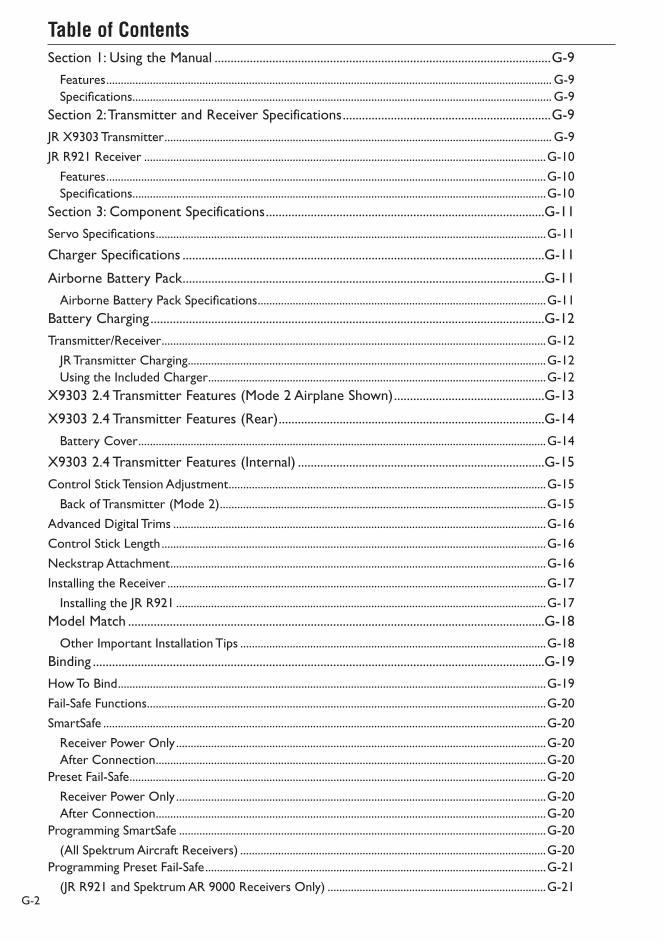
Table of Contents
G-2
Section 1: Using the Manual .........................................................................................................G-9
Features ......................................................................................................................................................... G-9Specifications ................................................................................................................................................ G-9
Section 2: Transmitter and Receiver Specifications .................................................................G-9
JR X9303 Transmitter ..................................................................................................................................... G-9
JR R921 Receiver ..........................................................................................................................................G-10
Features .......................................................................................................................................................G-10Specifications ..............................................................................................................................................G-10
Section 3: Component Specifications .......................................................................................G-11
Servo Specifications ......................................................................................................................................G-11
Charger Specifications .................................................................................................................G-11
Airborne Battery Pack .................................................................................................................G-11
Airborne Battery Pack Specifications ...................................................................................................G-11Battery Charging ...........................................................................................................................G-12
Transmitter/Receiver ....................................................................................................................................G-12
JR Transmitter Charging ...........................................................................................................................G-12Using the Included Charger ....................................................................................................................G-12
X9303 2.4 Transmitter Features (Mode 2 Airplane Shown) ...............................................G-13
X9303 2.4 Transmitter Features (Rear) ...................................................................................G-14
Battery Cover ............................................................................................................................................G-14
X9303 2.4 Transmitter Features (Internal) .............................................................................G-15
Control Stick Tension Adjustment .............................................................................................................G-15
Back of Transmitter (Mode 2) ................................................................................................................G-15
Advanced Digital Trims ................................................................................................................................G-16
Control Stick Length ....................................................................................................................................G-16
Neckstrap Attachment .................................................................................................................................G-16
Installing the Receiver ..................................................................................................................................G-17
Installing the JR R921 ...............................................................................................................................G-17Model Match ..................................................................................................................................G-18
Other Important Installation Tips .........................................................................................................G-18Binding .............................................................................................................................................G-19
How To Bind ...................................................................................................................................................G-19
Fail-Safe Functions .........................................................................................................................................G-20
SmartSafe ........................................................................................................................................................G-20
Receiver Power Only ...............................................................................................................................G-20After Connection ......................................................................................................................................G-20
Preset Fail-Safe ...............................................................................................................................................G-20
Receiver Power Only ...............................................................................................................................G-20After Connection ......................................................................................................................................G-20
Programming SmartSafe ..............................................................................................................................G-20
(All Spektrum Aircraft Receivers) .........................................................................................................G-20Programming Preset Fail-Safe .....................................................................................................................G-21
(JR R921 and Spektrum AR 9000 Receivers Only) ...........................................................................G-21

Table of Contents
G-3
Standard Range Testing ................................................................................................................G-21
Range Testing the X9303 2.4 ..................................................................................................................G-21Advanced Range Testing Using a Flight Log ............................................................................G-22
Advanced Range Testing the X9303 2.4 ...............................................................................................G-22Flight Log—Optional for JR R921 Receiver ...........................................................................G-23
Using the Flight Log ..................................................................................................................................G-23Receiver Power System Requirements ....................................................................................G-24
Recommended Power System Guidelines ...............................................................................................G-24
Flash Memory ................................................................................................................................G-25
Battery Alarm and Display ..........................................................................................................G-25
Tip on Using 2.4GHz Systems ...................................................................................................G-25
AIRPLANE – ACRO MODE .........................................................................................................A-1
Flight Modes ..................................................................................................................................................A-1
ACRO PROGRAMMING - PLEASE READ ...........................................................................................A-1
ACRO - GETTING STARTED – SYSTEM MENU BASICS ................................................................A-1
ACCESS THE SYSTEM MENU ......................................................................................................................A-2
SELECT A MODEL MEMORY .......................................................................................................................A-2
RESET THE MODEL ........................................................................................................................................A-3
TO ACTIVATE THE ACRO MODE ..............................................................................................................A-4
ENTER A NAME FOR THE MODEL ...........................................................................................................A-4
ACRO - SYSTEM MENU - ADVANCED FUNCTIONS ........................................................A-5
FLIGHT MODES ..............................................................................................................................................A-6
To Activate Flight Modes ................................................................................................................................A-7
TRIM:COM (Flight Modes) ............................................................................................................................A-8
D/R:SW (Flight Modes) ..................................................................................................................................A-8
SWITCH ASSIGNMENTS ..............................................................................................................................A-9
FLAP TRIM ON/OFF .......................................................................................................................................A-9
ACTIVATE/INHIBIT SWITCHES ............................................................................................................... A-10
WING TYPE ................................................................................................................................................... A-11
WING Parameter – (Wing Type) .............................................................................................................. A-12
V-tail (Wing Type) .......................................................................................................................................... A-14
Dual Channels (Wing Type) ........................................................................................................................ A-14
Twin E. (Wing Type) ...................................................................................................................................... A-16
TRIM STEP ...................................................................................................................................................... A-18
ACRO – FUNCTION LIST .................................................................................................................... A-19
REV.SW – SERVO REVERSING ................................................................................................................ A-19
SUB TRIM ........................................................................................................................................................ A-20
TRVL ADJ. – TRAVEL ADJUST ................................................................................................................... A-21
D/R & EXP – DUAL RATE AND EXPONENTIAL ............................................................................... A-22
THRO CURV – THROTTLE CURVE ........................................................................................................ A-23
FLAP SYS. – FLAP SYSTEM ......................................................................................................................... A-25
AUTO LAND (Flap System) ....................................................................................................................... A-26
ELEV – ELEVATOR COMPENSATION (Flap System) .......................................................................... A-27
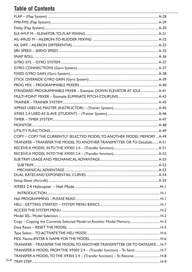
Table of Contents
G-4
FLAP – (Flap System) ................................................................................................................................... A-28
FM0-FM2 (Flap System) ............................................................................................................................... A-29
Delay (Flap System) ...................................................................................................................................... A-30
ELEFLP M – ELEVATOR-TO-FLAP MIXING ...................................................................................... A-31
AILRUD M – AILERON-TO-RUDDER MIXING ............................................................................. A-32
AIL DIFF. – AILERON DIFFERENTIAL ..................................................................................................... A-33
SRV. SPEED – SERVO SPEED ...................................................................................................................... A-35
SNAP ROLL.................................................................................................................................................... A-36
GYRO SYS. – GYRO SYSTEM .................................................................................................................... A-37
GYRO CONNECTIONS (Gyro System) ................................................................................................ A-37
FIXED GYRO GAIN (Gyro System) ........................................................................................................ A-38
STICK OVERRIDE GYRO GAIN (Gyro System) .................................................................................. A-39
PROG MIX – PROGRAMMABLE MIXERS ............................................................................................. A-40
STANDARD PROGRAMMABLE MIXER – Example: DOWN ELEVATOR AT IDLE ..................... A-41
MULTI-POINT MIXER – Example: ELIMINATE PITCH-COUPLING ............................................... A-43
TRAINER – TRAINER SYSTEM ................................................................................................................. A-45
XP9303 USED AS MASTER (INSTRUCTOR) – (Trainer System) ..................................................... A-45
X9303 2.4 USED AS SLAVE (STUDENT) – (Trainer System) ............................................................ A-46
TIMER – TIMER SYSTEM ............................................................................................................................. A-47
MONITOR...................................................................................................................................................... A-48
UTILITY FUNCTIONS ................................................................................................................................ A-49
COPY – COPY THE CURRENTLY SELECTED MODEL TO ANOTHER MODEL MEMORY ... A-49
TRANSFER – TRANSFER THE MODEL TO ANOTHER TRANSMITTER OR TO DataSafe ....... A-51
RECEIVE A MODEL INTO THE X9303 2.4 – (Transfer function)..................................................... A-51
RECEIVE A MODEL INTO THE X9303 2.4 – (Transfer function)..................................................... A-52
SUB TRIM USAGE AND MECHANICAL ADVANTAGE ..................................................................... A-53
SUB TRIM .................................................................................................................................................... A-53MECHANICAL ADVANTAGE ............................................................................................................... A-53
DUAL RATES AND EXPONENTIAL CURVES ..................................................................................... A-54
Setup Sheet (Aircraft) .................................................................................................................................. A-55
X9303 2.4 Helicopter – Heli Mode ...........................................................................................H-1
INTRODUCTION ...................................................................................................................................... H-1
Heli PROGRAMMING - PLEASE READ .................................................................................................... H-1
HELI - GETTING STARTED – SYSTEM MENU BASICS ....................................................................... H-1
ACCESS THE SYSTEM MENU ..................................................................................................................... H-2
Model SEL- Model Selection ......................................................................................................................... H-2
Copy – Copying the Currently Selected Model to Another Model Memory ................................... H-3
Data Reset – RESET THE MODEL ............................................................................................................. H-5
Type Select – TO ACTIVATE THE HELI MODE ....................................................................................... H-6
MDL Name-ENTER A NAME FOR THE MODEL ................................................................................... H-6
TRANSFER – TRANSFER THE MODEL TO ANOTHER TRANSMITTER OR TO DATASAFE .... H-7
TRANSFER A MODEL FROM THE X9303 2.4 – (Transfer function) – To Send .............................. H-7
TRANSFER A MODEL TO THE X9303 2.4 – (Transfer function) – To Receive ............................... H-8
TRIM STEP ........................................................................................................................................................ H-9

Table of Contents
G-5
HELI - SYSTEM MENU - ADVANCED FUNCTIONS ..........................................................................H-10
ADDITIONAL FLIGHT MODES 3 and 4 ...............................................................................................H-10
RUD TRIM: COM – (Flight Mode Trim Options) ...................................................................................H-11
SWITCH ASSIGNMENTS ...........................................................................................................................H-11
ACTIVATE/DEACTIVATE SWITCHES .....................................................................................................H-12
GOVERNOR PROGRAM ACTIVATION ................................................................................................H-12
SWASH TYP-SWASHPLATE TYPE ............................................................................................................H-13
Accessing the Swashplate Type Function .................................................................................................H-13
FUNCTION MODE .....................................................................................................................H-14
HELI – FUNCTION LIST ............................................................................................................................H-14
D/R & EXP – DUAL RATE AND EXPONENTIAL ...............................................................................H-14
Auto Dual Rate ..............................................................................................................................................H-15
REV.SW - SERVO REVERSING .................................................................................................................H-15
Sub Trim ...........................................................................................................................................................H-16
TRVL ADJ. – TRAVEL ADJUST ...................................................................................................................H-17
Swash Mix- CCPM SWASHPLATE Mixing .............................................................................................H-18
Variations of CCPM Mixing ....................................................................................................................H-18CCPM Servo Connection/Channel Numbers ....................................................................................H-18Accessing the Swashplate Mixing Function .........................................................................................H-19
CCPM Exponential (EXP) ...........................................................................................................................H-19
THRO HOLD- THROTTLE HOLD ..........................................................................................................H-20
Accessing the Throttle Hold Function .................................................................................................H-20Stick Auto/Auto Cut Setting .......................................................................................................................H-21
Hold Delay ......................................................................................................................................................H-21
THRO CURV – THROTTLE CURVES ......................................................................................................H-22
Accessing the Throttle Curve Function ...............................................................................................H-23Throttle Trim Lever Function .....................................................................................................................H-24
Hovering Throttle Lever ..............................................................................................................................H-24
Throttle Curve Exponential .......................................................................................................................H-24
Accessing the Throttle Curve Exponential Function ........................................................................H-24PIT. CURV/PITCH CURVES Function .......................................................................................................H-25
Accessing the Pitch Curve Function .....................................................................................................H-25Hovering Pitch Lever ....................................................................................................................................H-26
Example of Throttle Curve and Pitch Curve Settings ......................................................................H-26Accessing the Revolution Mixing Function .........................................................................................H-27Setting up Revolution Mixing..................................................................................................................H-27
REVO.MIX/Revo Mix Function: Non Heading Lock Gyros Only .......................................................H-27
GYRO SENS/Gyro Gain Function .............................................................................................................H-28
Accessing the Gyro Gain Function .......................................................................................................H-28Gyro Remote Gain Connections: JR G500T, JR770 and Others ...................................................H-29
Remote Gain Gyros .....................................................................................................................................H-29
Mixing – Cyclic-to-Throttle Mixing ...........................................................................................................H-29
Rudder-to-Throttle Mixing .........................................................................................................................H-30
Accessing the Cyclic-to-Throttle Function .........................................................................................H-31
Table of Contents
G-6
Aileron-to-Throttle and Elevator-to-Throttle Mixing ...........................................................................H-31
Setting the Desired Flight Modes for Cyclic-to-Throttle Mixing ...................................................H-31GOVERNOR- GOVERNOR FUNCTION .............................................................................................H-32
Accessing the Governor Function ........................................................................................................H-32PROG MIX 1-6 – PROGRAMMABLE MIXES 1 through 6 ..................................................................H-33
Swashplate Timing Mixes Example: Elevator-to-Aileron (Corrects Vertical Tracking)....................H-35
Swashplate Timing: Aileron-to-Elevator (Corrects Rolling Maneuvers) ............................................H-37
STANDARD PROGRAMMABLE MIXES – Example: Right Aileron with Positive Pitch ............H-39MULTI-POINT MIXES – Example: FMOD to Gear Mixing (Retract and other Functions) .........H-41
Trainer – Programmable Trainer System..................................................................................................H-44
X9303 2.4 USED AS MASTER (INSTRUCTOR) – (Trainer System) ............................................H-44X9303 2.4 USED AS SLAVE (STUDENT) – (Trainer System) ........................................................H-45
Timer – Timer System .................................................................................................................................H-46
MONITOR- SERVO MONITOR ...............................................................................................................H-47
Setup Sheet (Helicopter) .............................................................................................................................H-48
Sailplane – GLID Mode................................................................................................................... S-1
SYSTEM MODE GLID FEATURES ...........................................................................................................S-1
FUNCTION MODE GLID FEATURES ...................................................................................................S-1
System Mode ......................................................................................................................................................S-2
System Mode ......................................................................................................................................................S-2
To enter System Mode: ................................................................................................................................S-2Model Select .......................................................................................................................................................S-3
Copy – Copying the Currently Selected Model to Another Model Memory .....................................S-4
Model Name ......................................................................................................................................................S-6
Type Select ..........................................................................................................................................................S-6
Model Reset .......................................................................................................................................................S-7
TRANSFER – Transfer the Model to Another Transmitter or to DataSafe .........................................S-8
TRANSFER a model from the X9303 2.4 – (Transfer function) ............................................................S-8
TRANSFER a model to the X9303 2.4 – (Transfer function) .................................................................S-9
Trim Step .......................................................................................................................................................... S-10
Device Select ................................................................................................................................................... S-11
Flight Modes ................................................................................................................................................ S-11
Activating and Assigning Flight Modes ....................................................................................................... S-12
Motor Function .............................................................................................................................................. S-13
Flap and AUX Functions ............................................................................................................................... S-14
Activating / Inhibiting Channels .............................................................................................................. S-14Wing Type ........................................................................................................................................................ S-15
Function Mode ........................................................................................................................................... S-16
D/R & EXP – DUAL RATE AND EXPONENTIAL ................................................................................ S-18
REV.SW – SERVO REVERSING ................................................................................................................. S-19
SUB TRIM ......................................................................................................................................................... S-20
TRVL. ADJ - TRAVEL ADJUST ..................................................................................................................... S-21
Elevator-to-Flap Mix ...................................................................................................................................... S-21
Aileron-to-Flap Mix ....................................................................................................................................... S-22
Differential ....................................................................................................................................................... S-22

Table of Contents
G-7
Camber Adjust ................................................................................................................................................ S-23
Camber Mix .................................................................................................................................................... S-24
Aileron-to-Rudder Mix ................................................................................................................................. S-25
Butterfly Mix (Landing Flaps) ....................................................................................................................... S-26
Flap Rate........................................................................................................................................................... S-27
Motor Hold ..................................................................................................................................................... S-27
Programmable Curve Mix 1 (Programmed for Spoiler-to-Elevator Mix).......................................... S-28
PROG MIX - PROGRAMMABLE MIXERS ............................................................................................... S-29
MULTI-POINT PROGRAMMABLE MIXER ............................................................................................. S-33
Trainer – Programmable Trainer System................................................................................................... S-36
X9303 2.4 USED AS MASTER (INSTRUCTOR) – (Trainer System) ............................................. S-36X9303 2.4 USED AS SLAVE (STUDENT) – (Trainer System) ......................................................... S-37
Timer ................................................................................................................................................................ S-37
Monitor ............................................................................................................................................................ S-38
Programming a 6-Channel Sailplane by Engineering Manager John Adams ......................S-39
Channel Assignment .................................................................................................................................. S-41Step #1 Servo Assignment .......................................................................................................................... S-41
Step #2- System Mode .................................................................................................................................. S-42
Step #3 Selecting a Model Memory ........................................................................................................... S-42
Step #4 Selecting Model Type...................................................................................................................... S-43
Step #5 Naming a Model .............................................................................................................................. S-43
Step #6 Turning Off the Spoiler Stick Trim ............................................................................................... S-44
Step #7 Establishing Flight Modes .............................................................................................................. S-44
Step #8 Wing and Tail Type Select .............................................................................................................. S-45
Step #9 Entering FUNC.LIST ...................................................................................................................... S-45
Step #10 Servo Reversing ............................................................................................................................ S-46
Step #11 Sub Trim .......................................................................................................................................... S-47
Step #12 Travel Adjust ................................................................................................................................... S-48
Step #13 Butterfly (Landing Flaps) ............................................................................................................. S-48
Setting-up Flight Modes ............................................................................................................................ S-49Launch Mode Setup ................................................................................................................................... S-49
Step #14 Spoiler to Elevator Curve Mix (Programmable Mix 1) ....................................................... S-49
Step #15 Launch Pre-sets ............................................................................................................................ S-50
Step #16 Dual Rate and Exponential ......................................................................................................... S-51
Step #17 Elevator-to-Flap Mix .................................................................................................................... S-51
Step #18 Aileron-to-Flap .............................................................................................................................. S-52
Step #19 Aileron Differential ....................................................................................................................... S-52
Flaperon Mix ............................................................................................................................................... S-53Step #20 Flap Rate, Camber Mix and Camber Adjust ........................................................................... S-53
Step #21 Flap Rate, Camber Mix and Camber Adjust (continued) .................................................... S-54
Flaperon Mix ............................................................................................................................................... S-54Flaperon Mix Delay .................................................................................................................................... S-54Setting up Cruise Mode ............................................................................................................................ S-55
Step #22- Aileron-to-Rudder Mix ............................................................................................................. S-55
Step #23 Cruise Pre-sets ............................................................................................................................. S-56

G-8
Step #24 Dual Rate and Exponential ......................................................................................................... S-56
Step #25 Elevator-to-Flap Mix .................................................................................................................... S-57
Step #26 Aileron-to-Flap .............................................................................................................................. S-58
Step #27 Aileron Differential ....................................................................................................................... S-58
Flap Rate ...................................................................................................................................................... S-59Flaperon Mix ............................................................................................................................................... S-59
Step #28 Flap Rate, Camber Mix and Camber Adjust ........................................................................... S-59
Step #29 Flap Rate, Camber Mix and Camber Adjust (continued) .................................................... S-60
Flaperon Mix Delay .................................................................................................................................... S-60Setting Up Land Mode .............................................................................................................................. S-61
Step #30 Aileron-to-Rudder Mix .............................................................................................................. S-61
Step #31 Land Pre-sets ................................................................................................................................. S-62
Step #32 Dual Rate and Exponential ......................................................................................................... S-63
Step #33 Elevator-to-Flap Mix .................................................................................................................... S-64
Step #34 Aileron-to-Flap .............................................................................................................................. S-64
Step #35 Aileron Differential ....................................................................................................................... S-64
Flaperon Mix ............................................................................................................................................... S-65Flaperon Mix ............................................................................................................................................... S-65
Step #36 Flap Rate, Camber Mix and Camber Adjust ........................................................................... S-65
Step #37 Flap Rate, Camber Mix and Camber Adjust (continued) .................................................... S-66
Step #38 Aileron-to-Rudder Mix .............................................................................................................. S-66
Flaperon Mix Delay .................................................................................................................................... S-66Setup Sheet (Sailplane) .................................................................................................................................. S-67
Servo Precautions .......................................................................................................................................... W-1
General notes ................................................................................................................................................. W-1
Federal Aviation Administration .................................................................................................................. W-2
1. Purpose .................................................................................................................................................... W-22. Background .............................................................................................................................................. W-23. Operating Standards ............................................................................................................................. W-2Warning ........................................................................................................................................................ W-3Warranty Period ........................................................................................................................................ W-3Limited Warranty ....................................................................................................................................... W-3Damage Limits ............................................................................................................................................ W-3Safety Precautions ...................................................................................................................................... W-3Questions, Assistance, and Repairs ........................................................................................................ W-3
Warranty and Service Information ............................................................................................................ W-3
Warranty and Service Information ............................................................................................................ W-4
Inspection or Repairs ................................................................................................................................ W-4Warranty Inspection and Repairs ........................................................................................................... W-4Non-Warranty Repairs ............................................................................................................................. W-4Safety, Precautions, and Warnings ........................................................................................................... W-4Instructions for Disposal of WEEE by Users in the European Union ............................................ W-5FCC Information ........................................................................................................................................ W-5

JR X9303 Transmitter
Section 2: Transmitter and Receiver Specifications
Section 1: Using the Manual
G-9
JR’s X9303 2.4 offers airplane, helicopter and sailplane pilots sophisticated programming that JR’s 9303 is famous for with the added benefits of fully integrated Spektrum 2.4GHz DSM® radio link technology. DSM (Digital Spektrum Modulation) technology offers a far superior RF link than narrow band 72MHz FM and PCM systems, providing a higher level of confidence and safety. Now with even the most sophisticated models up to 9 channels, you’ll no longer have to wait for an
open frequency, worry about someone unintentionally powering up on the same frequency, or have to plan a frequency-based flight matrix for competition. And for response-critical aircraft like 3D helicopters and airplanes, latency (the time it takes for a stick input to translate to a servo output) is significantly reduced providing a more responsive precise connection to your model.
Features
• Fully integrated 2.4GHz Spektrum RF link
• Sophisticated three-model-type programming: Airplane, Helicopter, Sailplane
• Patented DuaLink™ Technology
• ModelMatch™
• ServoSync™
• Rolling Selector input
• Digital 3+1 trims
• 30-model memory
Specifications
• Model number—Airplane/Sailplane (JRP2910), Helicopter (JRP2920)
• Number of channels—9
• Modulation type—Direct Sequence Spread Spectrum DSM2/ DSM1 protocol
• Band—2.400 to 2.483GHz
• Spectral capacity—40 simultaneous systems
• Transmitter Current—180mA/DSM2 280mA/ DSM1
• Resolution—2048 w/R921 receiver
In the front of this manual you will find common transmitter features and specifications plus information on the included components and accessories. Guidelines for receiver and servo installation are also included. In each section of this manual (Air, Heli and Sailplane) are instructions for adjusting model-specific programming and functions. An explanation of the purpose of each programming function is provided, followed by an illustration of its corresponding LCD display and instructions on how to access and adjust the function.
A blank data sheet has been included at the end of each section, as well as on the JR web site. Once all data has been input for a particular model, it is highly recommended that you record these values and settings on a copy of the data sheet, so in the rare event of a loss of memory, these settings are available.
Note: The manual for the X9303 2.4 manual is posted online at www.horizonhobby.com in the support section or it can be ordered from your local hobby dealer or directly from Horizon Hobby.

JR R921 Receiver
G-10
The R921 receiver combines two internal with one or two (optional) remote receivers, offering superior path diversity. The radio system simultaneously transmits on two frequencies, creating up to four RF paths on two different 2.4GHz channels. This multi path redundancy, plus the fact that each of the up to 4 receivers are located in different locations throughout the aircraft exposes each
to a different RF environment creating a superior RF link in all conditions. The JR R921 allows the use of an optional Flight Log Data Recorder (SPM5940) to be used. The flight log plugs into the data port and provides quality of RF link data of the previous flight allowing the confirmation of the operational performance of the systems.
Features
• 9 channels
• 2 internal receivers
• 1 or 2 (optional) remote receiver(s)
• Patented multi-link technology
• Two types of fail-safe—SmartSafe and Preprogrammed fail-safe
• Flight Log compatible
Specifications
• Number of Channels—9
• Modulation—DSM2
• Band—2.400 to 2.4835GHz
• Dimensions (WxLxH)—.35”x2.06”x0.55”
• Weight—Main 15g/.6oz Remote 3g/.2 oz each
• Current—70mA
• Voltage range—3.5 to 9.6V
Note: The X9303 2.4 is compatible with all current Spektrum DSM aircraft receivers including:
AR6000 6-channel parkflyer receiver
AR6100 6-channel 3.5-gram parkflyer receiver
AR6200 6-channel full-range receiver
AR7000 7-channel full-range receiver
AR9000 9-channel full-range receiver
Important: When using the X9303 2.4 with parkflyer receivers (the AR6000 and AR6100), it’s imperative that these receivers only be flown in parkflyer-type aircraft (small electric airplanes or mini and micro helicopters). Flying receivers designed for parkflyers in larger aircraft could cause loss of control.

Servo Specifications
Section 3: Component Specifications
Charger Specifications
G-11
Type DS821
Torque 72 oz/in
Speed .19
Weight 1.5 oz
Size (in) (L x W x H) .74x1.50x1.47
Ball Bearing Yes
Motor 3-pole Ferrite
Model Number AD35M05
Input Voltage AC 120V, 60Hz
Output Current 11.6V Tx/110mAh, 5.8V Rx/110mAh
Charging Time 15 hours
Airborne Battery PackAirborne Battery Pack Specifications
Model Number B1100
Voltage 4.8V
Size (in) (L x W x H) 2.24 x 0.63 x 1.70
Weight (oz) 4.9

Transmitter/Receiver
Battery Charging
G-12
Note: It is imperative that you fully charge both the transmitter and the receiver battery packs prior to each flying session and that you check the condition of the receiver battery between each flight using a reliable battery tester with a built-in load. The included wall charger slow charges at a 110mA rate. In order to fully charge the included batteries, it’s necessary to leave the charger and batteries hooked up to the included wall charger for 15 hours.
An optional fast charger can be used to charge both the transmitter and receiver batteries, however, it’s imperative that the batteries are properly charged and the charge condition be checked prior to flight. False peaking is a common occurrence with many fast chargers (batteries giving an indication the battery is fully charged when in fact the battery is only partially charged). False peaking can lead to disastrous results and it is the pilot’s responsibility to verify the charge condition of the batteries before every flight. (Also see Receiver Power Requirements page G-24)
JR Transmitter Charging
The center pin on all JR® and Spektrum™ transmitters is negative. Therefore, the center pin on all JR chargers is negative, not positive. This is different from many other manufacturers’ chargers and radio systems. Beware of improper connections based on “color-coded” wire leads, as they may not apply in this instance. You must make sure that the center pin of your JR transmitter is always connected to the negative pole for correct polarity.
Note: When using a fast charger to charge the transmitter battery do not exceed 1.5 amps (or 1500mAh) charge rate or damage to the transmitter or battery damage can occur.
Using the Included Charger
The pilot lamps should always be on during the charging operation. If not, check to make sure that both the transmitter and receiver are switched off.
Do not use the charger for equipment other than JR. The charging plug polarity may not be the same. Equipment damage can result.
Do not use other manufacturers’ after-market accessories that plug into the transmitter’s charging jack if you are unsure of the polarity compatibility with your radio. Seek expert advice to avoid possible damage.
During the charging operation, the charger’s temperature is slightly elevated.
CENTER PIN IS
NEGATIVE
OUTSIDE IS POSITIVE
CHARGER PIGTAIL FOR RECEIVER
CHARGER PIGTAIL FOR TRANSMITTER
BLACK TO POSITIVE
RED TO NEGATIVE
RIGHT SIDE OF TRANSMITTER
RED–POSITIVE / BROWN–NEGATIVE / ORANGE–SIGNAL

X9303 2.4 Transmitter Features (Mode 2 Airplane Shown)
G-13
Trainer Button
Gear Switch
Flap Switch
Elevator Dual Rate
Flap Trim
Lever
AUX4/ Rudder Dual
RateAux Trim
Aileron Dual Rate
AUX2
Mix Switch
Lever
Elevator/ Aileron Stick
Throttle/ Rudder Stick
Rudder Trim
Throttle Trim
List Button
Enter Button
Clear Button
Power Switch
Aileron Trim
Elevator Trim
Rolling Selector
LCD Display
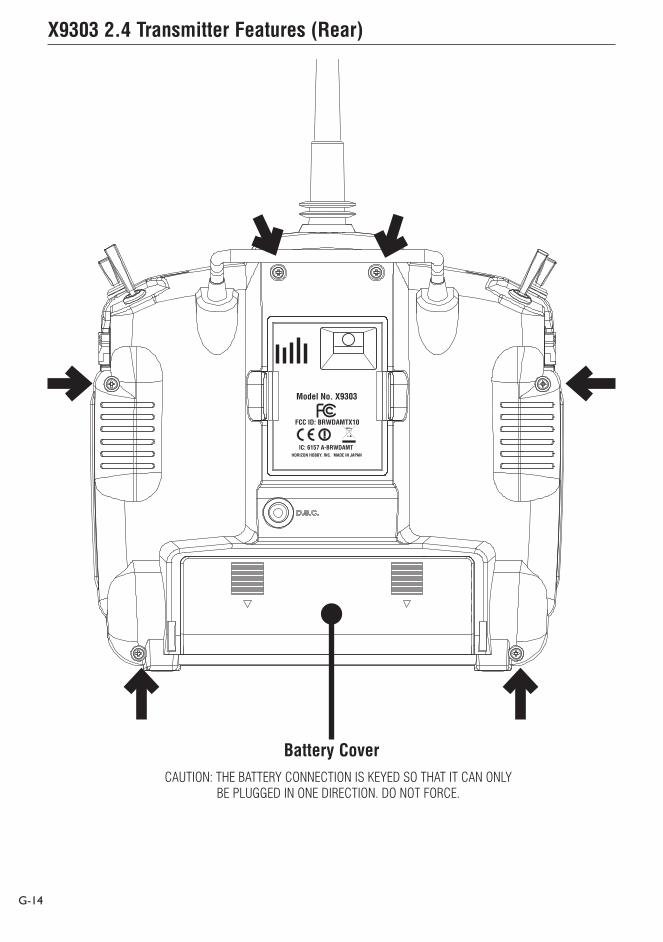
X9303 2.4 Transmitter Features (Rear)
G-14
Model No. X9303
FCC ID: BRWDAMTX10
IC: 6157 A-BRWDAMTHORIZON HOBBY, INC. MADE IN JAPAN
Battery CoverCAUTION: THE BATTERY CONNECTION IS KEYED SO THAT IT CAN ONLY
BE PLUGGED IN ONE DIRECTION. DO NOT FORCE.

X9303 2.4 Transmitter Features (Internal)
Control Stick Tension Adjustment
G-15
Remove the six transmitter screws from the back cover as shown on page G-14. Remove the transmitter back, being careful not to cause damage to any components.
Adjust each gimbal tension screw for desired tension (counter-clockwise to loosen stick tension; clockwise to tighten stick tension). When adjusting the throttle ratchet tension, make sure that the adjusting screw does not touch the PC board after adjustment is complete.
Back of Transmitter (Mode 2)
THROTTLE TENSION SCREW
RUDDER TENSION SCREW
ELEVATOR TENSION SCREW
AILERON TENSION SCREW
Control Stick Length
Neckstrap Attachment
G-16
Advanced Digital Trims
The X9303 2.4 features Advanced digital trims. On the Normal display screen, if a trim lever is moved, the screen will automatically change to display the graphic position for the trim being adjusted. The X9303 2.4’s Aileron, Elevator, and Rudder trim levers feature an audible center trim beep. This is helpful in determining the trim levers’ center position during flight. In addition, the frequency of each trim step changes from full right/up to full left/down, allowing the pilot to be aware of the general trim position audibly without looking at the transmitter.
By using the Trim Step Function located in the System Mode, the amount of travel per each trim step can be adjusted as needed to match your specific application.
Please note that when the X9303 2.4 transmitter is turned off, the trim values are stored in memory and are recalled when the system is turned back on.
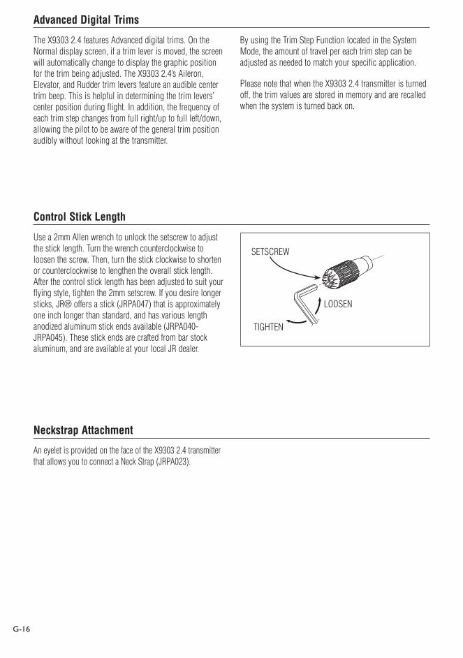
Use a 2mm Allen wrench to unlock the setscrew to adjust the stick length. Turn the wrench counterclockwise to loosen the screw. Then, turn the stick clockwise to shorten or counterclockwise to lengthen the overall stick length. After the control stick length has been adjusted to suit your flying style, tighten the 2mm setscrew. If you desire longer sticks, JR® offers a stick (JRPA047) that is approximately one inch longer than standard, and has various length anodized aluminum stick ends available (JRPA040-JRPA045). These stick ends are crafted from bar stock aluminum, and are available at your local JR dealer.
An eyelet is provided on the face of the X9303 2.4 transmitter that allows you to connect a Neck Strap (JRPA023).
LOOSEN
TIGHTEN
SETSCREW

Installing the Receiver
G-17
Installing the JR R921
The JR R921 incorporates dual internal receivers, and one or two remote receivers offering the security of up to four simultaneous RF links for the ultimate in multi-path RF security. Two internal receivers are located on the main PC board, while a third remote receiver must be plugged into one of the antenna ports in order for the system to operate. Optionally, a second remote receiver can be plugged into the remaining remote antenna port giving a total of four operational receivers. By locating these receivers in different locations throughout the aircraft, each receiver is exposed to its own RF environment, greatly improving path diversity (the ability of the receiver to see the signal in all conditions).
Note: The JR R921 requires that at least one remote receiver be used.
Install the main receiver using the same method you would use to install a conventional receiver in your aircraft. Typically wrap the main receiver in protective foam and fasten it in place using rubber bands or Velcro straps. Alternately in electric models or in jets (low vibration), it’s acceptable to use thick double-sided foam tape to fasten the main receiver in place.
Mounting the remote receiver(s) in a different location(s), from the primary receiver, gives tremendous improvements in path diversity. Essentially each receiver sees a different RF environment and this is the key to maintaining a solid RF link, even in aircraft that have substantial conductive materials, (i.e. Turbine engines with metal tail pipes, carbon fiber, tuned pipes, etc.) which can attenuate the signal.
Using double-sided foam tape, (servo tape) mount the remote receiver(s) keeping the remote antenna(s) at least 2 inches away from the primary antenna. Ideally the antennas will be oriented perpendicular to each other; however, we’ve found this to not be critical. 6-inch, 9-inch, 12-inch, 24-inch and 36-inch leads are available and in sophisticated aircraft, we’ve found it best to mount the remote receivers in different parts of the aircraft keeping the remote antennas as far away as practical from any conductive materials. A typical installation would include the main receiver mounted in the conventional location in the fuselage and the remote antennas in the nose (jets) in the top turtle deck and even in the tail. The optimum location is as far away from any conductive materials as practical.

G-18
In helicopters, there is generally enough room on the servo tray to achieve the necessary separation. If necessary, a mount can be made using clear plastic to mount the external antenna as shown below.
Other Important Installation Tips
1. The servos should be mounted using rubber grommets and brass eyelets to isolate them from vibration. Do not over-tighten the mounting screws; this will negate the vibration absorption effect of the rubber grommets. The following diagram will assist you in properly mounting your servo.
The brass eyelets are pushed from the bottom up in the rubber grommets. When the servo screw is tightened securely, it provides the proper security as well as the proper vibration isolation for your servo.
2. The servos must be able to move freely over their entire range of travel. Make sure that the control linkages do not bind or impede the movement of any of the servos.
3. Mount all switches away from the engine exhaust and away from any high vibration areas. Make sure the switch operates freely and is able to operate over its full travel.
Model MatchThe X9303 2.4 features patented ModelMatch technology that prevents the operation of a model if the wrong model memory is selected. During binding, the receiver actually learns and remembers the specific model memory (1 thru 30) that the transmitter is currently programmed to. Later if the incorrect model memory in the transmitter is selected and the receiver is turned on, the model simply won’t operate, preventing a possible crash. Change programming to the correct model memory and you’re set to fly.
Servo Mounting Tab
Screw
Rubber Grommet
Brass Eyelet
G-19
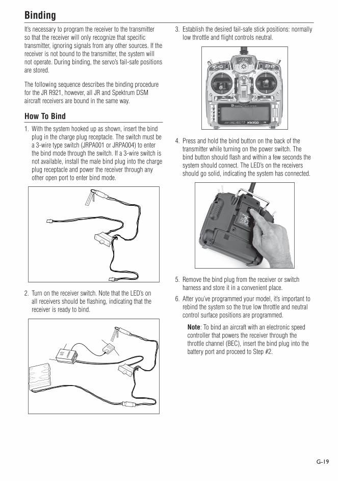
It’s necessary to program the receiver to the transmitter so that the receiver will only recognize that specific transmitter, ignoring signals from any other sources. If the receiver is not bound to the transmitter, the system will not operate. During binding, the servo’s fail-safe positions are stored.
The following sequence describes the binding procedure for the JR R921, however, all JR and Spektrum DSM aircraft receivers are bound in the same way.
How To Bind1. With the system hooked up as shown, insert the bind
plug in the charge plug receptacle. The switch must be a 3-wire type switch (JRPA001 or JRPA004) to enter the bind mode through the switch. If a 3-wire switch is not available, install the male bind plug into the charge plug receptacle and power the receiver through any other open port to enter bind mode.
REMO
VE BEFORE U
SE
2. Turn on the receiver switch. Note that the LED’s on all receivers should be flashing, indicating that the receiver is ready to bind.
AR90
00
3. Establish the desired fail-safe stick positions: normally low throttle and flight controls neutral.
4. Press and hold the bind button on the back of the transmitter while turning on the power switch. The bind button should flash and within a few seconds the system should connect. The LED’s on the receivers should go solid, indicating the system has connected.
5. Remove the bind plug from the receiver or switch harness and store it in a convenient place.
6. After you’ve programmed your model, it’s important to rebind the system so the true low throttle and neutral control surface positions are programmed.
Note: To bind an aircraft with an electronic speed controller that powers the receiver through the throttle channel (BEC), insert the bind plug into the battery port and proceed to Step #2.
Binding

G-20
The JR R921 receiver features two types of fail-safe: SmartSafe and Preset Fail-safe.
SmartSafe
This type of fail-safe is especially ideal for most types of electric aircraft and is also recommended for most types of gas- and glow-powered airplanes and helicopters. Here’s how SmartSafe works.
Receiver Power Only
When the receiver only is turned on (no transmitter signal is present), all servos except for the throttle are driven to their preset fail-safe positions, normally control surfaces at neutral and the landing gear down. These fail-safe positions are stored in the receiver during binding. At this time the throttle channel has no output, to avoid operating or arming the electronic speed control. In glow-powered models, the throttle servo has no input so it remains in its current position.
After Connection
When the transmitter is turned on and after the receiver connects to the transmitter, normal control of all channels occurs. After the system makes a connection, if loss of signal occurs, SmartSafe drives the throttle servo only to its preset fail-safe position (low throttle) that was set during binding. All other channels hold their last position. When the signal is regained, the system immediately (less than 4 ms) regains control.
Preset Fail-Safe
Preset fail-safe is ideal for sailplanes and is preferred by some modelers for their glow- and gas-powered aircraft.
Receiver Power Only
When the receiver only is turned on (no transmitter signal is present) all servos except for the throttle are driven to their preset fail-safe positions, normally control surfaces at neutral and the landing gear down. These fail-safe positions are stored in the receiver during binding. At this time the throttle channel has no output, to avoid operating or arming the electronic speed control. In glow-powered models, the throttle servo has no input so it remains in its current position.
After Connection
When the transmitter is turned on and after the receiver connects to the transmitter, normal control of all channels occurs. After the system makes a connection, if loss of signal occurs preset fail-safe drives all servos to their preset fail-safe positions. For sailplanes, it’s recommended that the spoilers/flaps deploy to de-thermalize the aircraft, preventing a flyaway. Some powered modelers prefer to use this fail-safe system to program a slight turn and low throttle to prevent their aircraft from flying away. When the signal is regained, the system immediately (in less than 4 ms regains control).
Programming SmartSafe
(All Spektrum Aircraft Receivers)
During the binding process the bind plug is left in throughout the process and is removed only after the receiver connects to the transmitter. After the connection is made, confirmed by operating the servos, the bind plug can be removed. The receiver is now programmed for SmartSafe.
Fail-Safe Functions

G-21
(JR R921 and Spektrum AR 9000 Receivers Only)
During the binding process, the bind plug is inserted in the bind port or in the charge jack, then the receiver is powered up. The LED’s in each receiver should blink, indicating that the receiver is in bind mode. Now before binding the receiver to the transmitter and with the receiver in bind mode, remove the bind plug. The LED’s will still be blinking. With the control sticks and switches in the desired fail-safe positions, bind the transmitter to the receiver by pressing and holding the bind buttons on the back of the transmitter/module and turning on the transmitter. The system should connect in less than 15 seconds. The receiver is now programmed for preset fail-safe.
Note: Fail-safe positions are stored via the stick and switch positions on the transmitter during binding.
Standard Range TestingBefore each flying session, and especially with a new model, it’s important to perform a range check. The X9303 2.4 incorporates a range testing system which, when the bind button on the transmitter is pressed and held, reduces the output power, allowing a range check.
Range Testing the X9303 2.4
1. With the model resting on the ground, stand 30 paces (approx. 90 feet) away from the model.
2. Face the model with the transmitter in your normal flying position and depress and hold the bind button on the back of the transmitter. This causes reduced power output from the transmitter.
3. You should have total control of the model with the button depressed at 30 paces (90 feet).
4. If control issues exist, call the JR Service Center at 1-877-504-0233 for further assistance.
Programming Preset Fail-Safe

G-22
While the above Standard Range Testing procedure is recommended for most sport aircraft, for sophisticated aircraft that contain significant amounts of conductive/reflective materials (i.e. turbine-powered jets, some types of scale aircraft, aircraft with carbon fuselages, etc.) the following advanced range check will confirm that all internal and remote receivers are operating optimally and that the installation (position of the receivers) is optimized for the specific aircraft. This Advanced Range Check allows the RF performance of each individual internal and remote receiver to be evaluated and to optimize the locations of each individual remote receiver.
Advanced Range Testing the X9303 2.4
1. Plug a flight log (optional) into the data port in the JR R921 receiver and turn on the system (transmitter and receiver).
2. Advance the Flight Log until F- frame losses are displayed, by pressing the button on the flight log.
3. Have a helper hold your aircraft while he observes the Flight Log data.
4. Standing 30 paces away from the model, face the model with the transmitter in your normal flying position and depress and hold the bind button on the back of the transmitter. This causes reduced power output from the transmitter.
5. Have your helper position the model in various orientations (nose up, nose down, nose toward the transmitter, nose away from the transmitter, etc.) while your helper is watching the Flight Log, noting any correlation between the aircraft’s orientation and Frame Losses. Do this for 1 minute. The timer on the X9303 can be used here. For giant-scale aircraft, it’s recommended that the airplane be tipped up on its nose and rotated 360 degrees for one minute, then record the data. Next place the airplane on its wheels and do a second test, rotating the aircraft in all directions for one minute.
6. After one minute, release the bind button. A successful range check will have recorded zero frame losses. Scrolling the Flight Log through the Antenna fades (A, B, L, R) allow you to evaluate the performance of each receiver. Antenna fades should be relatively uniform. If a specific antenna is experiencing a high degree of fades, then that antenna should be moved to a different location.
7. A successful Advanced test will yield the following:
H- 0 holds
F- 0 frame losses
A, B, R, L- Antenna fades will typically be less than 100. It’s important to compare the relative antenna fades and if a particular receiver has a significantly higher antenna fades (2 to 3X), then the test should be redone, and if the same results occur, move the offending receiver to a different location.
Advanced Range Testing Using a Flight Log
G-23
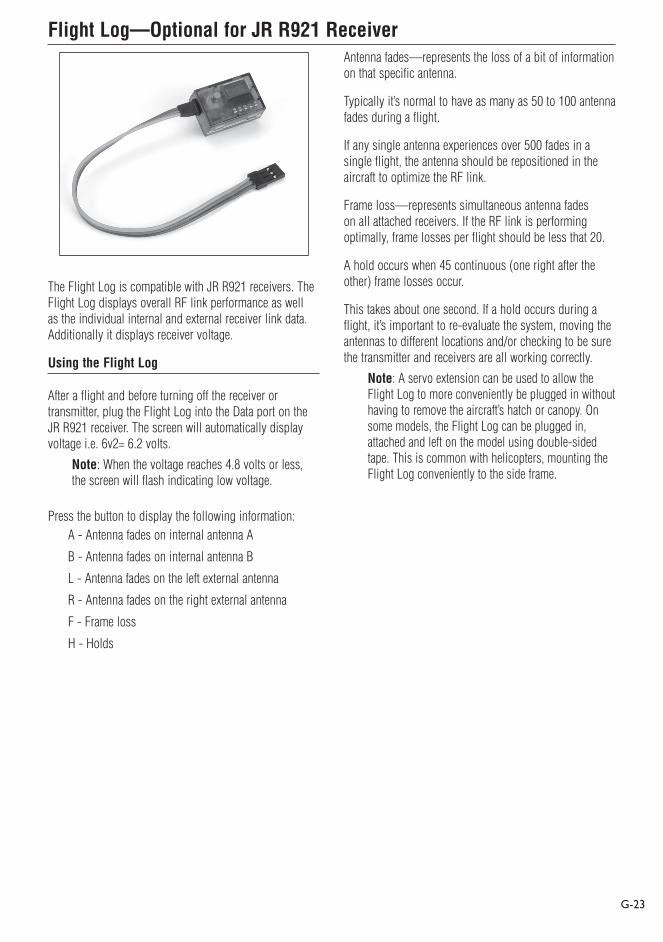
The Flight Log is compatible with JR R921 receivers. The Flight Log displays overall RF link performance as well as the individual internal and external receiver link data. Additionally it displays receiver voltage.
Using the Flight Log
After a flight and before turning off the receiver or transmitter, plug the Flight Log into the Data port on the JR R921 receiver. The screen will automatically display voltage i.e. 6v2= 6.2 volts.
Note: When the voltage reaches 4.8 volts or less, the screen will flash indicating low voltage.
Press the button to display the following information:A - Antenna fades on internal antenna A
B - Antenna fades on internal antenna B
L - Antenna fades on the left external antenna
R - Antenna fades on the right external antenna
F - Frame loss
H - Holds
Antenna fades—represents the loss of a bit of information on that specific antenna.
Typically it’s normal to have as many as 50 to 100 antenna fades during a flight.
If any single antenna experiences over 500 fades in a single flight, the antenna should be repositioned in the aircraft to optimize the RF link.
Frame loss—represents simultaneous antenna fades on all attached receivers. If the RF link is performing optimally, frame losses per flight should be less that 20.
A hold occurs when 45 continuous (one right after the other) frame losses occur.
This takes about one second. If a hold occurs during a flight, it’s important to re-evaluate the system, moving the antennas to different locations and/or checking to be sure the transmitter and receivers are all working correctly.
Note: A servo extension can be used to allow the Flight Log to more conveniently be plugged in without having to remove the aircraft’s hatch or canopy. On some models, the Flight Log can be plugged in, attached and left on the model using double-sided tape. This is common with helicopters, mounting the Flight Log conveniently to the side frame.
Flight Log—Optional for JR R921 Receiver

G-24
With all radio installations, it is vital that the onboard power system provides adequate power without interruption to the receiver even when the system is fully loaded (servos at maximum flight loads). This becomes especially critical with giant-scale models that utilize multiple high torque/ high current servos. Inadequate power systems that are unable to provide the necessary minimum voltage to the receiver during flight loads have become the number one cause of in-flight failures. Some of the power system components that affect the ability to properly deliver adequate power include: the selected receiver battery pack (number of cells, capacity, cell type, state of charge), switch harness, battery leads, regulator (if used), power bus (if used).
While the R921 receivers’ minimum operational voltage is 3.5-volts, it is highly recommended the system be tested per the guidelines below to a minimum acceptable voltage of 4.8-volts during ground testing. This will provide head room to compensate for battery discharging or if the actual flight loads are greater than the ground test loads.
Recommended Power System Guidelines1. When setting up large or complex aircraft with multiple
high torque servos, it’s highly recommended a current and voltmeter (Hangar 9 HAN172) be used. Plug the voltmeter in an open channel port in the receiver and with the system on, load the control surfaces (apply pressure with your hand) while monitoring the voltage at the receiver. The voltage should remain above 4.8 volts even when all servos are heavily loaded.
Note: The optional Flight Log has a built in voltmeter and it can be used to perform this test.
2. With the current meter inline with the receiver battery lead, load the control surfaces (apply pressure with your hand) while monitoring the current. The maximum continuous recommended current for a single heavy-duty servo/battery lead is three amps while short duration current spikes of up to five amps are acceptable. Consequently, if your system draws more than three amps continuous or five amps for short durations, a single battery pack with a single switch harness plugged into the receiver for power will be inadequate. It will be necessary to use multiple packs of the same capacity with multiple switches and multiple leads plugged into the receiver.
3. If using a regulator, it’s important that the above tests are done for an extended period of 5 minutes. When current passes through a regulator, heat is generated and this heat causes the regulator to increase resistance, which in turn causes even more heat to build up (thermal runaway). While a regulator may provide adequate power for a short duration, it’s important to test its ability over time as the regulator may not be able to maintain voltage at significant power levels.
4. For really large aircraft or complex models (for example 35% and larger or jets), multiple battery packs with multiple switch harnesses are necessary or, in many cases, one of the commercially available power boxes/ busses is recommended. No matter what power systems you choose, always carry out test #1 above making sure that the receiver is constantly provided with 4.8 volts or more under all conditions.
5. The latest generation of Nickel Metal Hydride batteries incorporate a new chemistry mandated to be more environmentally friendly. These batteries, when charged with peak detection fast chargers, have tendencies to false peak (not fully charge) repeatedly. These include all brands of Ni-MH batteries. If using Ni-MH packs, be especially cautious when charging making absolutely sure that the battery is fully charged. It is recommended to use a charger that can display total charge capacity. Note the number of mAh put into a discharged pack to verify it has been charged to full capacity.
Receiver Power System Requirements

G-25
All preprogrammed data is protected by a flash memory that guards against memory loss main transmitter battery failure.
Flash Memory
Battery Alarm and DisplayWhen the transmitter voltage drops below 9.0 volts DC, the display flashes “BATT LOW” and an alarm sounds.
If you are flying when this occurs, land immediately.
Tip on Using 2.4GHz SystemsWhile your DSM equipped 2.4GHz system is intuitive to operate, functioning nearly identically to 72MHz systems, following are a few common questions from customers:1. Q: Which do I turn on first, the transmitter or the
receiver?
A: If the receiver is turned on first, all servos except for the throttle will be driven to their preset fail-safe positions set during binding. At this time, the throttle channel doesn’t put out a pulse position preventing the arming of electronic speed controllers or, in the case of an engine-powered aircraft, the throttle servo remains in its current position. When the transmitter is then turned on, the transmitter scans the 2.4GHz band and acquires two open channels. Then the receiver that was previously bound to the transmitter scan the band and finds the GUID (Globally Unique Identifier code) stored during binding. The system then connects and operates normally.
If the transmitter is turned on first, the transmitter scans the 2.4GHz band and acquires two open channels. When the receiver is then turned on for a short period (the time it takes to connect), all servos except for the throttle are driven to their preset fail-safe positions while the throttle has no output pulse; The receiver scans the 2.4GHz band looking for the previously stored GUID; and when it locates the specific GUID code and confirms uncorrupted repeatable packet information the system connects and normal operation takes place. Typically this takes 2 to 6 seconds.
2. Q: Sometimes the system takes longer to connect and sometimes it doesn’t connect at all?
A: In order for the system to connect (after the receiver is bound) the receiver must receive a large number of continuous (one after the other) uninterrupted perfect packets from the transmitter in order to connect. This process is purposely critical of the environment, ensuring that it’s safe to fly when the system does connect. If the transmitter is too close to the receiver (less that 4 feet) or if the transmitter is located near metal objects (metal transmitter case, the bed of a truck, the top of a metal work bench, etc.) connection will take longer, and in some cases, connection will not occur as the system is receiving reflected 2.4GHz energy from itself and is interpreting this and unfriendly noise. Moving the system away from metal objects or moving the transmitter away from the receiver and powering the system up again will cause a connection to occur. This only happens during the initial connection. Once connected, the system is locked-in and, should a loss of signal occur (fail-safe), the system connects immediately (4ms) when signal is regained.

G-26
3. Q: I’ve heard that the DSM system is less tolerant of low voltage. Is that correct?
A: All DSM receivers have an operational voltage range of 3.5 to 9 volts. With most systems, this is not a problem as most servos cease to operate at around 3.8 volts. When using multiple high current draw servos with a single or inadequate battery/power source, heavy momentary loads can cause the voltage to dip below this 3.5-volt threshold, causing the entire system (servos and receiver) to brown out. When the voltage drops below the low voltage threshold (3.5 volts), the DSM receiver must reboot (go through the start-up process of scanning the band and finding the transmitter) and this can take several seconds. Please read the receiver power requirement on page G-24 as this explains how to test for and prevent this occurrence.
4. Q: Sometimes my receiver loses its bind and won’t connect, requiring rebinding. What happens if the bind is lost in flight?
A: The receiver will never lose its bind unless it’s instructed to. It’s important to understand that during the binding process the receiver not only learns the GUID (code) of the transmitter but the transmitter learns and stores the type of receiver that it’s bound to. If the bind button on the transmitter is pressed at any time and the transmitter is turned on, the transmitter looks for the binding protocol signal from a receiver. If no signal is present, the transmitter no longer has the correct information to connect to a specific receiver and in essence the transmitter has been “unbound” from the receiver. We’ve had several customers that use transmitter stands or trays that unknowingly depress the bind button and the system is then turned on, losing the necessary information to allow the connection to take place. We’ve also had customers that didn’t fully understand the range test process and pushed the bind button before turning on the transmitter, also causing the system to “lose its bind.” If, when turning on, the system fails to connect, one of the following has occurred:
• The wrong model has been selected in the model memory (Model Match).
• The transmitter is near conductive material (transmitter case, truck bed, etc.) and the reflected 2.4GHz energy is preventing the system from connecting (see #2 above).
• The bind button was unknowingly (or knowingly) depressed and the transmitter was turned on previously, causing the transmitter to no longer recognize the receiver.
5. Q: Can I use a 3-cell Li-Po pack in my transmitter
A: No. All current JR and Spektrum transmitters are designed to operate using a 9.6-volt transmitter pack. A fully charged 3-cell Li-Po pack puts out 12.6 volts. This higher voltage can overload the power-regulating transistor causing damage and or failure, possibly in flight. Many of our customers have experienced failures using 3-cell Li-Po packs and their use in JR and Spektrum transmitters is highly advised against. The X9303 2.4 system will operate for over 15 hours using a 2700mAh Ni-MH battery.
6. Q: How important is it that I test my system using a flight log?
A: For most sport airplanes and helicopters, the use of the flight log is unnecessary. For sophisticated aircraft, especially those that have significant conductive materials within the airframe (i.e. jets, scale airplanes, etc.), the Flight Log offers an extra measure of confidence that all radio components are working optimally. The Flight Log is an important tool that allows the confirmation that the installation (position of the internal and remote receivers relative to the conductive materials in the aircraft) is optimized and that the RF (radio) link is operating at the highest levels of performance.
Tip on Using 2.4GHz Systems (continued)