Embed Size (px)
Citation preview
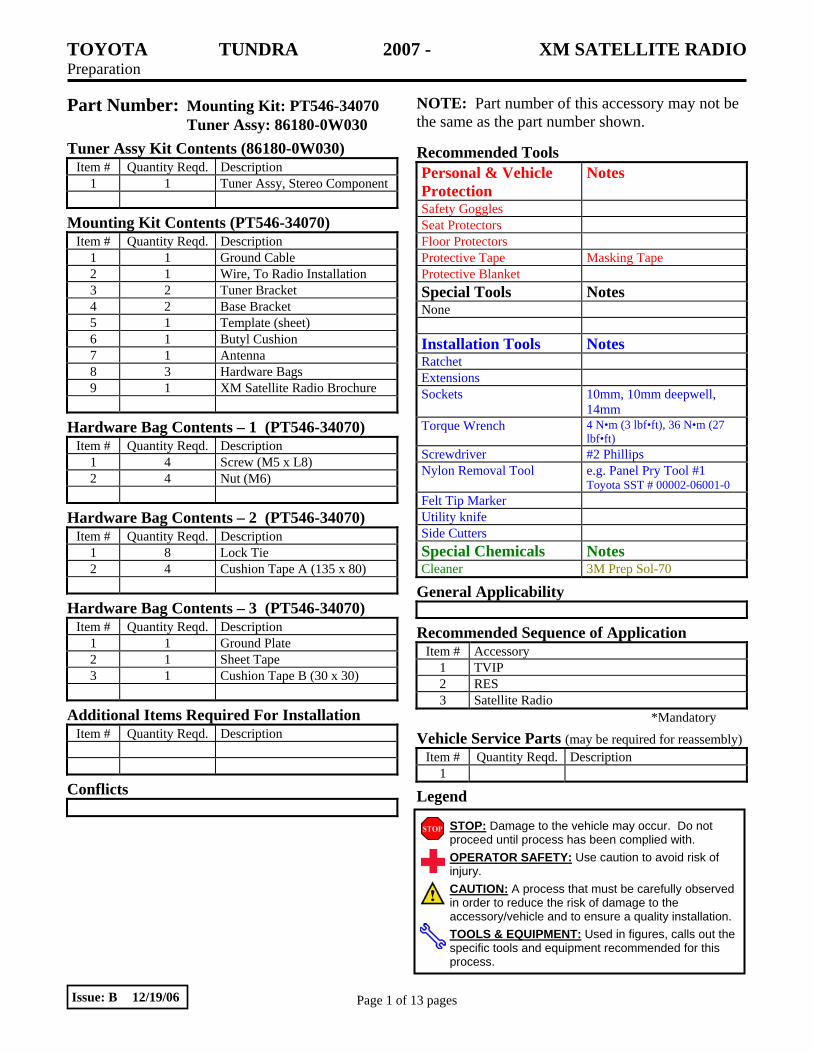
TOYOTA TUNDRA 2007 - XM SATELLITE RADIO Preparation
Page 1 of 13 pages Issue: B 12/19/06
Part Number: Mounting Kit: PT546-34070 Tuner Assy: 86180-0W030
NOTE: Part number of this accessory may not be the same as the part number shown.
Tuner Assy Kit Contents (86180-0W030) Item # Quantity Reqd. Description
1 1 Tuner Assy, Stereo Component
Mounting Kit Contents (PT546-34070) Item # Quantity Reqd. Description
1 1 Ground Cable 2 1 Wire, To Radio Installation 3 2 Tuner Bracket 4 2 Base Bracket 5 1 Template (sheet) 6 1 Butyl Cushion 7 1 Antenna 8 3 Hardware Bags 9 1 XM Satellite Radio Brochure
Hardware Bag Contents – 1 (PT546-34070) Item # Quantity Reqd. Description
1 4 Screw (M5 x L8) 2 4 Nut (M6)
Hardware Bag Contents – 2 (PT546-34070) Item # Quantity Reqd. Description
1 8 Lock Tie 2 4 Cushion Tape A (135 x 80)
Hardware Bag Contents – 3 (PT546-34070) Item # Quantity Reqd. Description
1 1 Ground Plate 2 1 Sheet Tape 3 1 Cushion Tape B (30 x 30)
Additional Items Required For Installation Item # Quantity Reqd. Description
Conflicts
Recommended Tools Personal & Vehicle Protection
Notes
Safety Goggles Seat Protectors Floor Protectors Protective Tape Masking Tape Protective Blanket Special Tools Notes None Installation Tools Notes Ratchet Extensions Sockets 10mm, 10mm deepwell,
14mm Torque Wrench 4 N•m (3 lbf•ft), 36 N•m (27
lbf•ft) Screwdriver #2 Phillips Nylon Removal Tool e.g. Panel Pry Tool #1
Toyota SST # 00002-06001-0 Felt Tip Marker Utility knife Side Cutters Special Chemicals Notes Cleaner 3M Prep Sol-70
General Applicability
Recommended Sequence of Application Item # Accessory
1 TVIP 2 RES 3 Satellite Radio
*Mandatory
Vehicle Service Parts (may be required for reassembly) Item # Quantity Reqd. Description
1
Legend
STOP: Damage to the vehicle may occur. Do not proceed until process has been complied with. OPERATOR SAFETY: Use caution to avoid risk of injury. CAUTION: A process that must be carefully observed in order to reduce the risk of damage to the accessory/vehicle and to ensure a quality installation.TOOLS & EQUIPMENT: Used in figures, calls out the specific tools and equipment recommended for this process.
TOYOTA TUNDRA 2007 - XM SATELLITE RADIO Preparation
Page 2 of 13 pages Issue: B 12/19/06
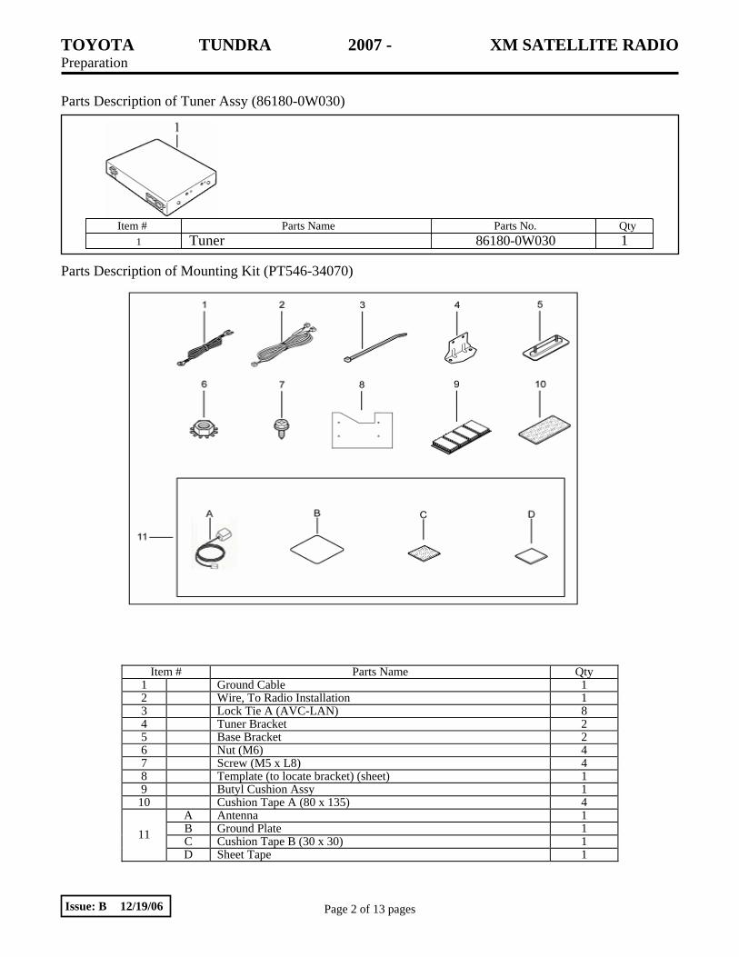
Parts Description of Tuner Assy (86180-0W030)
Parts Description of Mounting Kit (PT546-34070)
Item # Parts Name Qty 1 Ground Cable 1 2 Wire, To Radio Installation 1 3 Lock Tie A (AVC-LAN) 8 4 Tuner Bracket 2 5 Base Bracket 2 6 Nut (M6) 4 7 Screw (M5 x L8) 4 8 Template (to locate bracket) (sheet) 1 9 Butyl Cushion Assy 1
10 Cushion Tape A (80 x 135) 4 A Antenna 1 B Ground Plate 1 C Cushion Tape B (30 x 30) 1 11
D Sheet Tape 1
Item # Parts Name Parts No. Qty 1 Tuner 86180-0W030 1

TOYOTA TUNDRA 2007 - XM SATELLITE RADIO Procedure
Page 3 of 13 pages Issue: B 12/19/06
Care must be taken when installing this accessory to ensure that damage does not occur to the vehicle. The installation of this accessory should follow approved guidelines to ensure a quality installation. These guidelines can be found in the Accessory Installation Practices document. The Accessory Installation Practices document covers such items as:
• Vehicle Protection (use of covers and blankets, cleaning chemicals, etc.). • Safety (eye protection, rechecking torque procedure, etc.). • Vehicle Disassembly/Reassembly (panel removal, part storage, etc.). • Electrical Component Disassembly/Reassembly (battery disconnection, connector removal, etc.).
Please see your Toyota dealer for a copy of the Accessory Installation Practices document.
1. Remove the negative (–) battery cable (Fig. 1-1)
(a) Place Driver’s seat in middle position.
(b) Protect fender before starting.
(c) Place removed vehicle components on protective blanket.
(d) Remove the negative (–) battery cable.
CAUTION: Be careful not to touch the positive terminal.
2. Vehicle Disassembly
(a) Remove driver side front scuff plate. (Fig. 2-1)
(1) Using nylon pry tool, disengage ten (10) clips and remove the driver side front scuff plate.
(b) Remove driver side cowl trim panel. (Fig. 2-2)
(1) Remove plastic nut.
(2) Use nylon pry tool to disengage the two (2) clips; then remove the cowl trim panel.
Fig. 2-2
Plastic nut Nylon pry tool
Clips (x2)
Fig. 2-1
Scuff plate
Clips (x10)
Nylon pry tool
Fig. 1-1
10 mm socket Negative battery cable
Cowl trim panel
TOYOTA TUNDRA 2007 - XM SATELLITE RADIO Procedure
Page 4 of 13 pages Issue: B 12/19/06
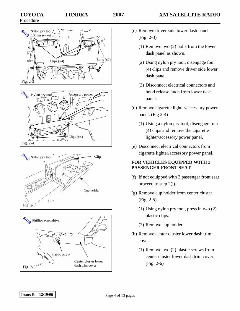
(c) Remove driver side lower dash panel. (Fig. 2-3)
(1) Remove two (2) bolts from the lower dash panel as shown.
(2) Using nylon pry tool, disengage four (4) clips and remove driver side lower dash panel.
(3) Disconnect electrical connectors and hood release latch from lower dash panel.
(d) Remove cigarette lighter/accessory power panel. (Fig 2-4)
(1) Using a nylon pry tool, disengage four (4) clips and remove the cigarette lighter/accessory power panel.
(e) Disconnect electrical connectors from cigarette lighter/accessory power panel.
FOR VEHICLES EQUIPPED WITH 3 PASSENGER FRONT SEAT
(f) If not equipped with 3 passenger front seat proceed to step 2(j).
(g) Remove cup holder from center cluster. (Fig. 2-5)
(1) Using nylon pry tool, press in two (2) plastic clips.
(2) Remove cup holder.
(h) Remove center cluster lower dash trim cover.
(1) Remove two (2) plastic screws from center cluster lower dash trim cover. (Fig. 2-6)
Fig. 2-6
Plastic screw
Phillips screwdriver
Center cluster lower dash trim cover
Fig. 2-4
Accessory power
Clips (x4)
Nylon pry tool
Fig. 2-3
Clips (x4)
Nylon pry tool 10 mm socket
Bolts (x2)
Fig. 2-5
Cup holder
Clip
Clip Nylon pry tool

TOYOTA TUNDRA 2007 - XM SATELLITE RADIO Procedure
Page 5 of 13 pages Issue: B 12/19/06
(2) Using nylon pry tool, disengage two (2) clips and remove center cluster lower dash trim cover. (Fig. 2-7)
(i) Remove center cluster cup holder tray and trim panel. (Fig 2-8)
(1) Remove four (4) screws and one (1) hex bolt as shown.
(2) Disengage four (4) clips and remove cup holder tray and trim panel.
(j) Remove the HVAC control panel.
(1) Disengage five (5) clips and pull right side of upper instrument panel toward you to provide adequate clearance to remove the HVAC control panel. (Fig 2-9)
(2) Using nylon pry tool, disengage four (4) clips and remove the HVAC control panel. (Fig. 2-10)
(3) Remove electrical connectors from HVAC control panel.
NOTE: When removing electrical connectors, always pull on the connector, not the wire.
Fig. 2-7
Phillips screwdriver, Nylon pry tool
Plastic screw
Clips x 2
Fig. 2-9 Nylon pry tool
Clips (x5), right side of panel
Pull rt. side of inst. panel to clear HVAC panel
Fig. 2-10
Clips (x4)
Nylon pry tool
10mm socket, Phillips screwdriver, Nylon Pry Tool
Fig. 2-8
Screws x 2
Screws x 2Hex Bolt
Clips x 2
Clips x 2
TOYOTA TUNDRA 2007 - XM SATELLITE RADIO Procedure
Page 6 of 13 pages Issue: B 12/19/06
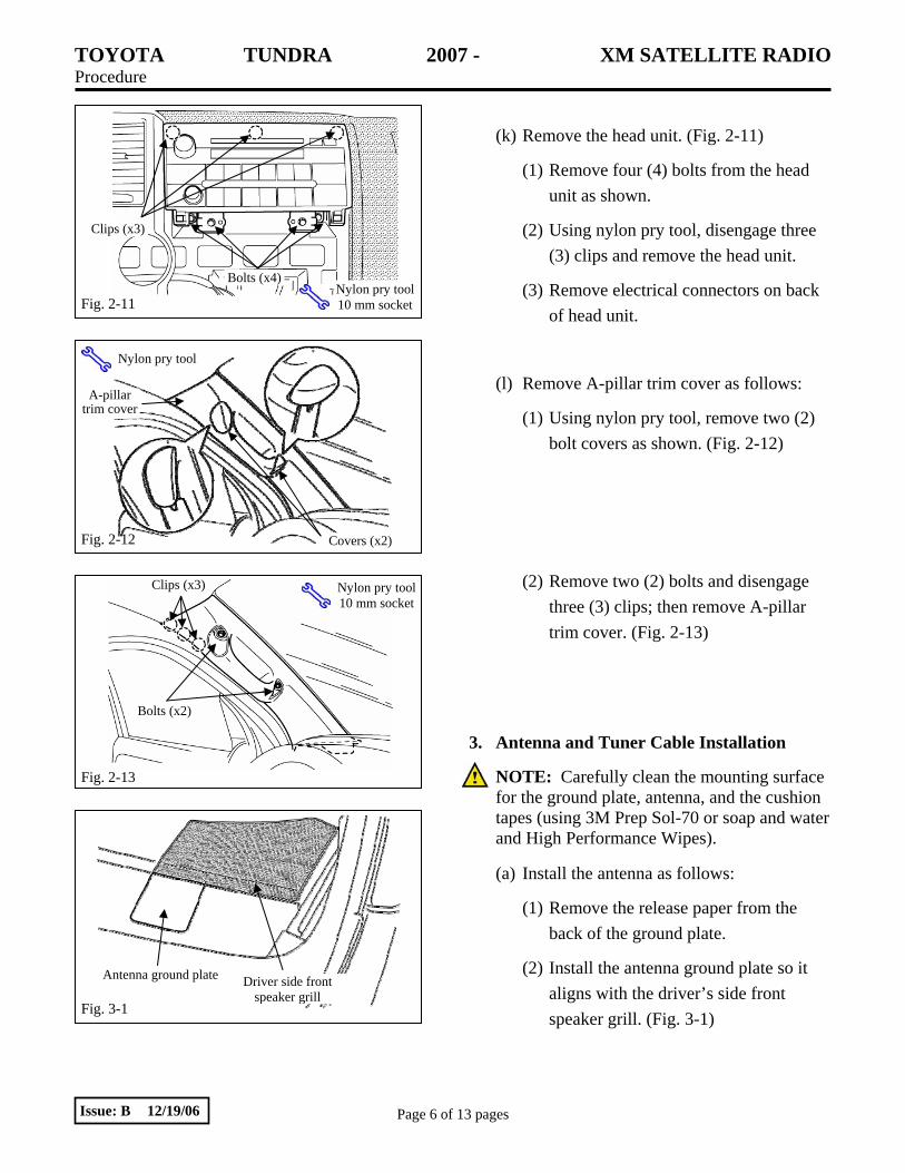
(k) Remove the head unit. (Fig. 2-11)
(1) Remove four (4) bolts from the head unit as shown.
(2) Using nylon pry tool, disengage three (3) clips and remove the head unit.
(3) Remove electrical connectors on back of head unit.
(l) Remove A-pillar trim cover as follows:
(1) Using nylon pry tool, remove two (2) bolt covers as shown. (Fig. 2-12)
(2) Remove two (2) bolts and disengage three (3) clips; then remove A-pillar trim cover. (Fig. 2-13)
3. Antenna and Tuner Cable Installation
NOTE: Carefully clean the mounting surface for the ground plate, antenna, and the cushion tapes (using 3M Prep Sol-70 or soap and water and High Performance Wipes).
(a) Install the antenna as follows:
(1) Remove the release paper from the back of the ground plate.
(2) Install the antenna ground plate so it aligns with the driver’s side front speaker grill. (Fig. 3-1)
Antenna ground plate Driver side front speaker grill
Fig. 3-1
Antenna ground plate Driver side front speaker grill
Fig. 2-13
Clips (x3)
Bolts (x2)
Nylon pry tool10 mm socket
Fig. 2-11
Clips (x3)
Bolts (x4) Nylon pry tool10 mm socket
Fig. 2-12
Nylon pry tool
A-pillar trim cover
Covers (x2)
TOYOTA TUNDRA 2007 - XM SATELLITE RADIO Procedure
Page 7 of 13 pages Issue: B 12/19/06
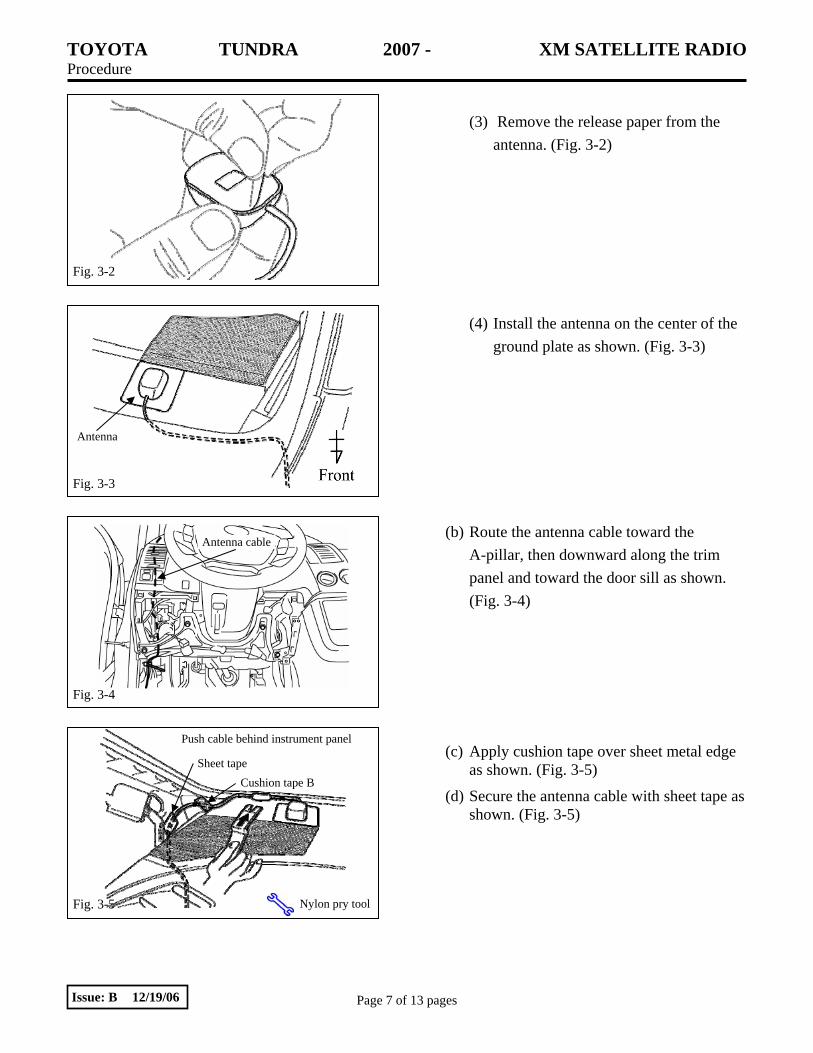
(3) Remove the release paper from the
antenna. (Fig. 3-2)
(4) Install the antenna on the center of the ground plate as shown. (Fig. 3-3)
(b) Route the antenna cable toward the A-pillar, then downward along the trim panel and toward the door sill as shown. (Fig. 3-4)
(c) Apply cushion tape over sheet metal edge as shown. (Fig. 3-5)
(d) Secure the antenna cable with sheet tape as shown. (Fig. 3-5)
Fig. 3-4
Antenna cable
Fig. 3-5
Sheet tape Cushion tape B
Nylon pry tool
Push cable behind instrument panel
Fig. 3-3
Antenna
Fig. 3-2
TOYOTA TUNDRA 2007 - XM SATELLITE RADIO Procedure
Page 8 of 13 pages Issue: B 12/19/06
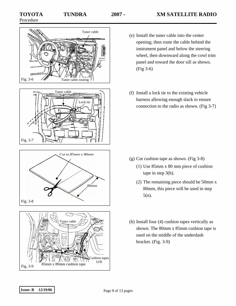
(e) Install the tuner cable into the center
opening; then route the cable behind the instrument panel and below the steering wheel, then downward along the cowl trim panel and toward the door sill as shown. (Fig 3-6)
(f) Install a lock tie to the existing vehicle
harness allowing enough slack to ensure connection to the radio as shown. (Fig 3-7)
(g) Cut cushion tape as shown. (Fig 3-8)
(1) Use 85mm x 80 mm piece of cushion tape in step 3(h).
(2) The remaining piece should be 50mm x 80mm, this piece will be used in step 5(n).
(h) Install four (4) cushion tapes vertically as shown. The 80mm x 85mm cushion tape is used on the middle of the underdash bracket. (Fig. 3-9)
Fig. 3-9
Tuner cable
85mm x 80mm cushion tape Cushion tapes
(x4)
Fig. 3-8
80mm
Cut to 85mm x 80mm
Fig. 3-7
Lock tie
Tuner cable
50mm
Tuner cable
Tuner cable routing Fig. 3-6
Tuner cable
Tuner cable routing

TOYOTA TUNDRA 2007 - XM SATELLITE RADIO Procedure
Page 9 of 13 pages Issue: B 12/19/06
(i) Install the ground cable. (Fig. 3-10)
(1) Loosen the existing ground screw.
(2) Route the ground cable into the kick panel area; then secure the ground cable terminal with the ground screw.
(j) Install one (1) lock tie to secure antenna cable, ground cable, and tuner cable to the existing vehicle harness. (Fig. 3-11)
(k) Route the tuner cable, the antenna cable,
and the ground cable along the door sill through the existing harness clamps. (Fig. 3-12)
4. DRIVER SEAT REMOVAL
(a) Remove driver seat bolts.
(1) Remove two (2) bolt covers and two (2) bolts from the rear mount brackets. (Fig 4-1)
Fig. 3-10
Ground cable
Ground screw
10 mm socket
Fig. 3-11 Lock tie (1)
Tuner cable
Ground cable
Antenna cable
Fig. 4-1
14 mm socket
Bolt (x2)
Bolt cover (x2)
Fig. 3-12

TOYOTA TUNDRA 2007 - XM SATELLITE RADIO Procedure
Page 10 of 13 pages Issue: B 12/19/06
(2) Remove two (2) bolts from the front mount brackets; then tilt the seat back to access the floor area. (Fig 4-2)
NOTE: Do not remove seat from vehicle. Tilt seat backwards. Do not remove electrical connectors.
5. Install Tuner
(a) Position the tuner template on the carpet and transfer the cut marks onto the carpet using a felt tip marker. Use reference point 1 for B-Cab and use reference 2 for C-Cab and D-Cab. (Fig. 5-1)
(b) Remove the template; then use a utility knife to create the four (4) holes identified by the template.
CAUTION: Ensure that the wire harness is not located under the cutting area prior to cutting carpet.
(c) Clean the base brackets and base bracket mounting area with 3M solvent.
(d) Install four (4) butyl cushions onto base brackets as shown. (Fig. 5-2)
NOTE: Dry fit brackets before adhearing butyl tape to vehicle.
(e) Insert base bracket studs underneath the carpet and through the cut holes; remove the release paper from the butyl cushions; then press the carpet downward to install the base brackets. (Fig. 5-3)
Fig. 5-3 Butyl cushions
Fig. 5-2
Butyl cushion (x4)
Base bracket (x2)
Fig. 5-1 Tuner template
Cut marks (x4)
Carpet punch Marker
Reference point 1 Reference point 2
Fig. 4-2
Bolt (x2)
14 mm socket
Driver seat
TOYOTA TUNDRA 2007 - XM SATELLITE RADIO Procedure
Page 11 of 13 pages Issue: B 12/19/06
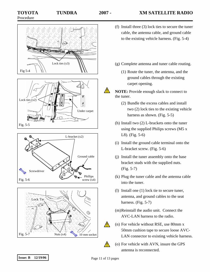
(f) Install three (3) lock ties to secure the tuner cable, the antenna cable, and ground cable to the existing vehicle harness. (Fig. 5-4)
(g) Complete antenna and tuner cable routing.
(1) Route the tuner, the antenna, and the ground cables through the existing carpet opening.
NOTE: Provide enough slack to connect to the tuner.
(2) Bundle the excess cables and install two (2) lock ties to the existing vehicle harness as shown. (Fig. 5-5)
(h) Install two (2) L-brackets onto the tuner using the supplied Philips screws (M5 x L8). (Fig. 5-6)
(i) Install the ground cable terminal onto the L-bracket screw. (Fig. 5-6)
(j) Install the tuner assembly onto the base bracket studs with the supplied nuts. (Fig. 5-7)
(k) Plug the tuner cable and the antenna cable into the tuner.
(l) Install one (1) lock tie to secure tuner, antenna, and ground cables to the seat harness. (Fig. 5-7)
(m) Reinstall the audio unit. Connect the AVC-LAN harness to the radio.
(n) For vehicle without RSE, use 80mm x 50mm cushion tape to secure loose AVC-LAN connector to existing vehicle harness.
(o) For vehicle with AVN, insure the GPS antenna is reconnected.
Fig. 5-5
Under carpet
Lock ties (x2)
Fig 5-4
Fig. 5-6
L-bracket (x2)
Phillips screw (x4)
Ground cable
Screwdriver
Fig. 5-7 Nuts (x4) 10 mm socket
Lock Tie
Lock ties (x3)
TOYOTA TUNDRA 2007 - XM SATELLITE RADIO Procedure
Page 12 of 13 pages Issue: B 12/19/06
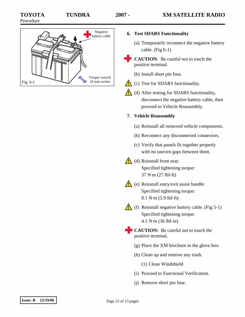
6. Test SDARS Functionality
(a) Temporarily reconnect the negative battery cable. (Fig 6-1)
CAUTION: Be careful not to touch the positive terminal.
(b) Install short pin fuse.
(c) Test for SDARS functionality.
(d) After testing for SDARS functionality, disconnect the negative battery cable, then proceed to Vehicle Reassembly.
7. Vehicle Reassembly
(a) Reinstall all removed vehicle components.
(b) Reconnect any disconnected connectors.
(c) Verify that panels fit together properly with no uneven gaps between them.
(d) Reinstall front seat: Specified tightening torque: 37 N·m (27 lbf-ft)
(e) Reinstall entry/exit assist handle: Specified tightening torque: 8.1 N·m (5.9 lbf-ft)
(f) Reinstall negative battery cable. (Fig 5-1) Specified tightening torque: 4.1 N·m (36 lbf-in)
CAUTION: Be careful not to touch the positive terminal.
(g) Place the XM brochure in the glove box.
(h) Clean up and remove any trash.
(1) Clean Windshield
(i) Proceed to Functional Verification.
(j) Remove short pin fuse.
Fig. 6-1
Negative battery cable
Torque wrench10 mm socket

TOYOTA TUNDRA 2007 - XM SATELLITE RADIO Checklist - these points MUST be checked to ensure a quality installation.
Check: Look For:
Page 13 of 13 pages Issue: B 12/19/06
Accessory Function Checks
Satellite Radio Tuner.
Receiver/player Assembly.
Vehicle Function Checks
Hazard switch.
Passenger's seat belt reminder light.
Passenger airbag ON/OFF light
Removed seat.
Proper operation of the removed seat lock mechanism.
HVAC (heating ventilation and air conditioning system.
Cigarette lighter and accessory power panel
Hood latch release mechanism
Cargo light switch
Power rear window control switch
RSCA switch
115VAC auxiliary switch
Traction control switch
*Verify the proper operation of the Satellite Radio Tuner.
*Verify the proper operation of the Receiver/player Assembly
*For vehicle with AVN, Perform On Screen System Check Mode.
*(Refer to the receiver assembly and radio owner's manuals.)
Verify proper operation of the hazard switch.
Verify proper operation of the passenger's seat belt reminder light. Verify proper operation of passenger airbag light.
Verify the removed seat is securely fastened.
Verify the proper operation of the removed seat lock mechanism.
Verify proper operation of the air conditioning system.
Verify proper operation of cigarette lighter and 12V accessory power panel.
Verify proper operation of hood latch release mechanism.
Verify proper operation of cargo light switch if equipped.
Verify rear window power control if equipped.
Verify proper operation of RSCA switch if equipped.
Verify proper operation of 115VAC auxiliary switch if equipped.
Verify proper operation of traction control switch if equipped.