Embed Size (px)
Citation preview
[12]
Guarantee:Terms and Conditions for UK & ROI (outside UK & ROI contact your local distributor)
We, Redring Xpelair Group, guarantee this product against faulty workmanship and material defects for a period of 5 years from the date of purchase.
In the event of a product breakdown during the guarantee period, you should initially contact your installer, before contacting Redring Xpelair Group on the Technical line number below providing that:
a) The appliance has been installed in a residential environment for domestic use only.
b) The appliance has been correctly installed and commissioned in accordance with our instructions and is being used on the supply circuit or voltage printed on the rating plate.
c) The appliance has been used in accordance with these instructions and has not been tampered with or otherwise subject to misuse, neglect or accident.
d) The appliance has been regularly maintained in accordance with these instructions and the airway is unobstructed.
e) The appliance has not been taken apart, modified or repaired except by a person authorised by us.
f) Evidence of the date of purchase in the form of an invoice or receipt will be required in order to qualify under the terms of this guarantee.
g) For the service work to be undertaken free of charge, the work must only be undertaken by Redring Xpelair Group Limited, or our approved agents.
h) Service under guarantee has no effect on the expiry date. The guarantee on any exchanged parts or product ends when the original guarantee period ends.
I) In the event of a product being returned to Redring Xpelair Group Limited and not found to be faulty, the product would be available for collection from the relevant premises within one month and if not collected it would be disposed of or delivered by Redring Xpelair Group Limited and a delivery charge made.
EXCLUSIONS
This guarantee does not cover damage or defects arising from poor or incorrect installation, improper use or lack of maintenance. It is the responsibility of the installer to check that the installation parameters meet the requirements of the product, and any relevant regulations.
If we are called out to a fault, which is subsequently identified as being an installation fault, we will make a charge. It is important that the routine checks are completed before calling us out, as many issues can be simply diagnosed and resolved.
We make no guarantees as to response times for repairs. We will endeavour to achieve the most timely response possible but while we indicate an average response time, this should not be taken as a guarantee.
The guarantee applies to a repair or replacement (at our discretion) of the product subject to the conditions above, and does not cover compensation for the loss of the product or consequential loss of any kind.
This guarantee does not affect your statutory rights.
Technical advice and service:Customers outside the UK- see international below.
UK: Xpelair have a comprehensive range of services including:
Free technical advice help-desk from engineers on all aspects of ventilation. Free design service, quotations and site surveys Service and maintenance contracts to suit all requirements.
Please ask for details:
By telephone on Techline: +44 (0) 7809 000430 By Fax on Techfax: +44 (0) 7809 000530 At the address shown
International:
Guarantee: Contact your local distributor or Xpelair direct for detailsTechnical Advice and Service: Contact your local Xpelair distributor.
Redring Xpelair Group LtdNewcombe House
Newcombe WayOrton Southgate
PeterboroughPE2 6SE
Tel: +44 (0) 1733 456789Fax: +44 (0) 1733 310606
www.redringxpelair.com
(A3) Booklet No: 24946AA (Revision A)
Xplus2 EC RFHMulti Point Ventilation Unit
Product Number: 92795AG
[2]
IMPORTANT CUSTOMER NOTES:This appliance can be used by children aged from 8 years and above and persons with reduced physical, sensory capabilities or lack of experience and knowledge, if they have been given supervision or instruction concerning the use of the appliance in a safe way and understand the hazards involved. Children shall not play with the appliance.Cleaning and maintenance of the appliance shall not be made by children.
WARNING: THE FAN AND ANCILLARY CONTROL EQUIPMENT MUST BE ISOLATED FROM THE POWER SUPPLY DURING INSTALATION OR MAINTENANCE.
Information on Maintenance and Operation:
For the Householder:Your home has been fitted with a highly energy efficient mechanical ventilation system. The system should consist of an Xplus2 EC RFH central mechanical extract fan, ducting, discharge grille and extract valves in the wet rooms, kitchen, bathroom and toilet. The correct working system will provide a healthy indoor atmosphere and will help eliminate condensation and unwanted odours. The Xplus2 EC RFH system is designed to operate with the Xplus 2 EC RFH switch supplied.The fan can be set to run in one of 4 modes:
Night-time speed setting where the fan provides background, trickle ventilation (the fan could also be set to run at this speed if the house is not fully occupied).
Day-time speed setting where the fan provides normal running conditions. Timed boost speed setting where the fan will run at High speed for a fixed 30 minute period. After this time
the fan will revert to the auto / Humidity speed setting condition. This setting would be used for the extract of cooking smells or moisture laden air. When this is in use it is advisable to open window vents or a window to provide replacement air.
Auto / Humidity speed setting where the fan runs at the day-time speed setting, adjusting to slow changes in natural humidity without increasing fan speed if humidity levels increase at a rate slower than 5% RH in 5 minutes. If humidity levels exceed 70% RH or increase quicker than 5% RH in 5 minutes the fan increases speed to the humidity speed setting. When humidity levels drop below 70% RH the fan continues to run at
[11]
This page has been left blank for the addition of any notes you may wish to make.
[10]
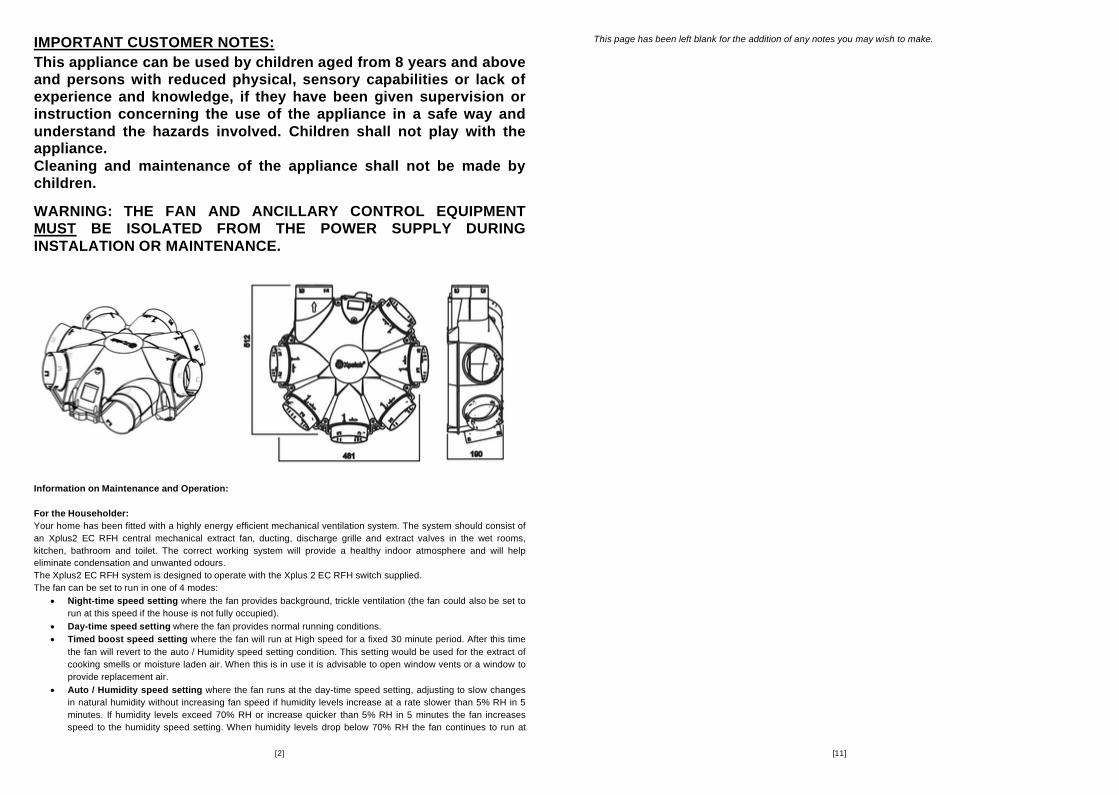
Ancillaries:The following ancillaries and spares are available for the Xplus2 EC RFH product range:
92433AW: �125mm Spigot
92435AW: Blanking Plate
Spares:
41983SK: Replacement electrical cover
42063SK: Replacement termination plug and screws
41987SK: Replacement Inlet Housing (Green)
[3]
humidity speed setting for a set time delay before returning to Day-time speed setting. The fan will default to this Auto setting when initially switched on.
All speeds are installer set on the integral PCB.The fan is designed to run continuously 24 hours a day. It is fitted with one of the world’s most energy efficient electronic motors.
Maintenance In normal running conditions the fan attracts very little dirt. However it may be advisable to have the unit inspected by your installer annually and clean if necessary (Making sure that water does not get into the motor or electrical termination box).
CE-Conformity:This unit meets all relevant CE standards.
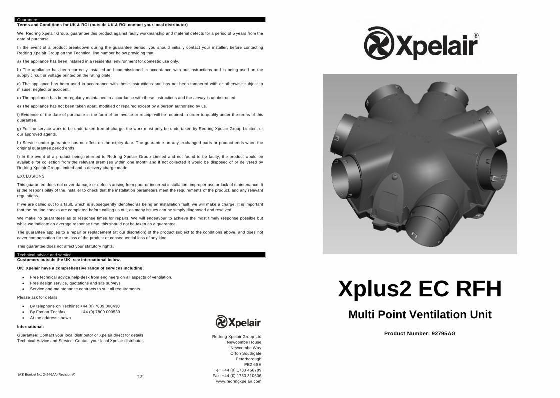
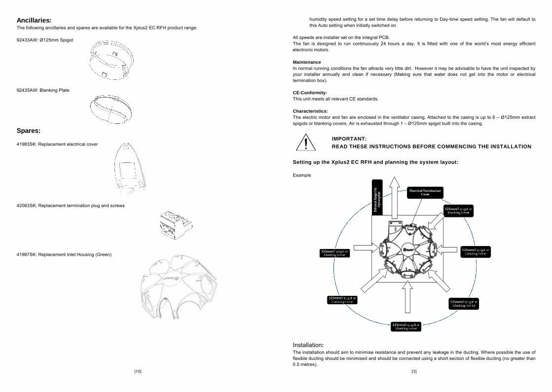
Characteristics:The electric motor and fan are enclosed in the ventilator casing. Attached to the casing is up to 6 – �125mm extract spigots or blanking covers. Air is exhausted through 1 – �125mm spigot built into the casing.
Setting up the Xplus2 EC RFH and planning the system layout:
Example
Installation:The installation should aim to minimise resistance and prevent any leakage in the ducting. Where possible the use of flexible ducting should be minimised and should be connected using a short section of flexible ducting (no greater than 0.5 metres).
IMPORTANT:READ THESE INSTRUCTIONS BEFORE COMMENCING THE INSTALLATION
[4]
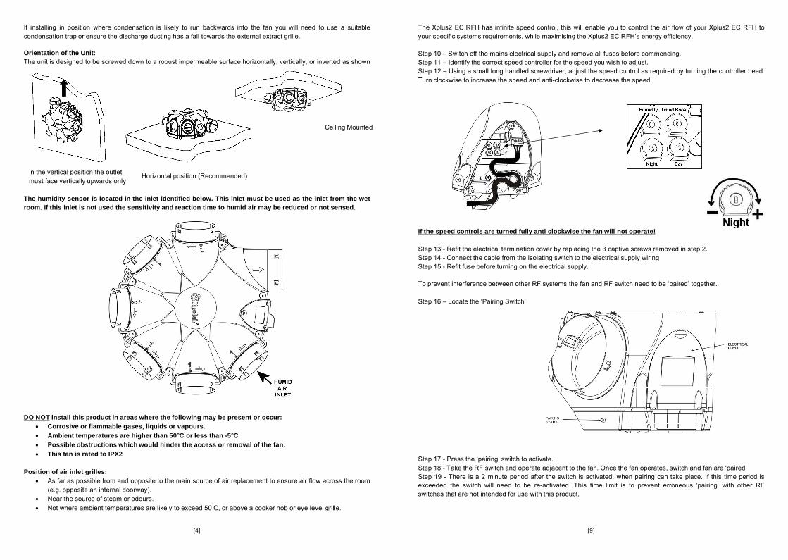
If installing in position where condensation is likely to run backwards into the fan you will need to use a suitable condensation trap or ensure the discharge ducting has a fall towards the external extract grille.
Orientation of the Unit:The unit is designed to be screwed down to a robust impermeable surface horizontally, vertically, or inverted as shown below.
The humidity sensor is located in the inlet identified below. This inlet must be used as the inlet from the wet room. If this inlet is not used the sensitivity and reaction time to humid air may be reduced or not sensed.
DO NOT install this product in areas where the following may be present or occur: Corrosive or flammable gases, liquids or vapours. Ambient temperatures are higher than 50°C or less than -5°C Possible obstructions which would hinder the access or removal of the fan. This fan is rated to IPX2
Position of air inlet grilles: As far as possible from and opposite to the main source of air replacement to ensure air flow across the room
(e.g. opposite an internal doorway). Near the source of steam or odours. Not where ambient temperatures are likely to exceed 50�C, or above a cooker hob or eye level grille.
Ceiling Mounted
Horizontal position (Recommended)In the vertical position the outlet must face vertically upwards only
[9]
The Xplus2 EC RFH has infinite speed control, this will enable you to control the air flow of your Xplus2 EC RFH to your specific systems requirements, while maximising the Xplus2 EC RFH’s energy efficiency.
Step 10 – Switch off the mains electrical supply and remove all fuses before commencing.Step 11 – Identify the correct speed controller for the speed you wish to adjust.Step 12 – Using a small long handled screwdriver, adjust the speed control as required by turning the controller head. Turn clockwise to increase the speed and anti-clockwise to decrease the speed.
If the speed controls are turned fully anti clockwise the fan will not operate!
Step 13 - Refit the electrical termination cover by replacing the 3 captive screws removed in step 2.Step 14 - Connect the cable from the isolating switch to the electrical supply wiring Step 15 - Refit fuse before turning on the electrical supply.
To prevent interference between other RF systems the fan and RF switch need to be ‘paired’ together.
Step 16 – Locate the ‘Pairing Switch’
Step 17 - Press the ‘pairing’ switch to activate.Step 18 - Take the RF switch and operate adjacent to the fan. Once the fan operates, switch and fan are ‘paired’Step 19 - There is a 2 minute period after the switch is activated, when pairing can take place. If this time period is exceeded the switch will need to be re-activated. This time limit is to prevent erroneous ‘pairing’ with other RF switches that are not intended for use with this product.
[8]
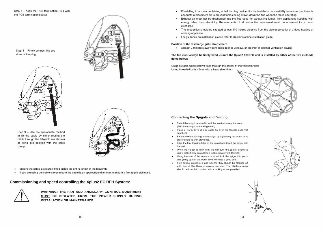
Ensure the cable is securely fitted inside the entire length of the labyrinth. If you are using the cable clamp ensure the cable is an appropriate diameter to ensure a firm grip is achieved.
Commissioning and speed controlling the Xplus2 EC RFH System:
WARNING: THE FAN AND ANCILLARY CONTROL EQUIPMENT MUST BE ISOLATED FROM THE POWER SUPPLY DURING INSTALATION OR MAINTENANCE.
Step 7 – Align the PCB termination Plug with the PCB termination socket
Step 8 – Firmly connect the two sides of the plug
Step 9 – Use the appropriate method to fix the cable by either routing the cable through the labyrinth (as shown) or fixing into position with the cable clamp.
[5]
If installing in a room containing a fuel burning device, it’s the installer’s responsibility to ensure that there is adequate replacement air to prevent fumes being drawn down the flue when the fan is operating.
Exhaust air must not be discharged into the flue used for exhausting fumes from appliances supplied with energy other than electricity. Requirements of all authorities concerned must be observed for exhaust discharge.
The inlet grilles should be situated at least 5.0 metres distance from the discharge outlet of a flued heating or cooking appliance.
For guidance on installation please refer to Xpelair’s online installation guide.
Position of the discharge grille atmosphere: At least 2.0 meters away from open door or window, or the inlet of another ventilation device.
The fan must always be firmly fixed, ensure the Xplus2 EC RFH unit is installed by either of the two methods listed below:
Using suitable wood screws fixed through the corner of the ventilator boxUsing threaded bolts ≤5mm with a head size ≥8mm
Connecting the Spigots and Ducting
Select the spigot required to suit the ventilation requirements: (�125mm spigot or blanking cover)
Place a worm drive clip or cable tie over the flexible duct (not supplied).
Fix the flexible ducting to the spigot by tightening the worm drive clip or cable tie (not provided).
Align the four locating tabs on the spigot and insert the spigot into the unit.
Once the spigot is flush with the unit turn the spigot clockwise until it locks firmly into position (approximately 30 degrees)
Using the one of the screws provided lock the spigot into place and gently tighten the worm drive to create a good seal.
If an extract spigot(s) is not required they should be blanked off with one of the blanking covers provided. The blanking cover should be fixed into position with a locking screw provided.
[6]
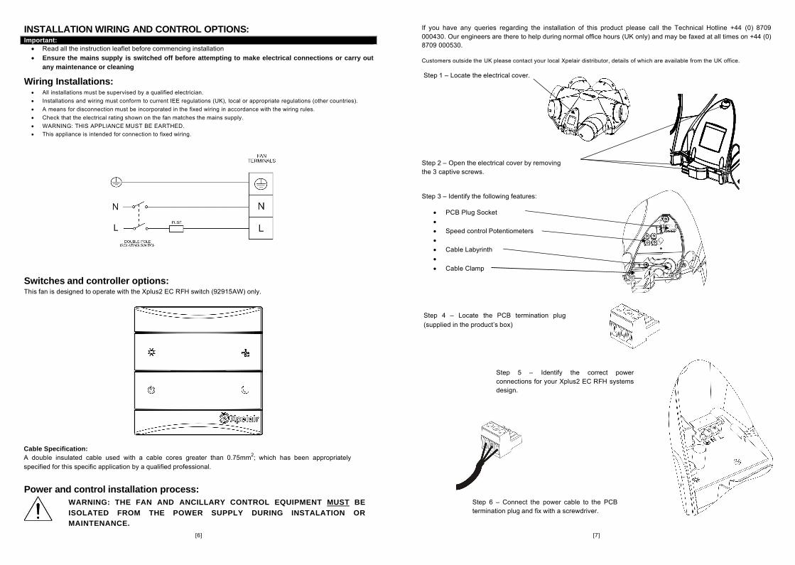
INSTALLATION WIRING AND CONTROL OPTIONS:Important: Read all the instruction leaflet before commencing installation Ensure the mains supply is switched off before attempting to make electrical connections or carry out
any maintenance or cleaning
Wiring Installations: All installations must be supervised by a qualified electrician. Installations and wiring must conform to current IEE regulations (UK), local or appropriate regulations (other countries). A means for disconnection must be incorporated in the fixed wiring in accordance with the wiring rules. Check that the electrical rating shown on the fan matches the mains supply. WARNING: THIS APPLIANCE MUST BE EARTHED. This appliance is intended for connection to fixed wiring.
Switches and controller options:This fan is designed to operate with the Xplus2 EC RFH switch (92915AW) only.
Power and control installation process:
Cable Specification: A double insulated cable used with a cable cores greater than 0.75mm2; which has been appropriately specified for this specific application by a qualified professional.
WARNING: THE FAN AND ANCILLARY CONTROL EQUIPMENT MUST BE ISOLATED FROM THE POWER SUPPLY DURING INSTALATION OR MAINTENANCE.
[7]
If you have any queries regarding the installation of this product please call the Technical Hotline +44 (0) 8709000430. Our engineers are there to help during normal office hours (UK only) and may be faxed at all times on +44 (0)8709 000530.
Customers outside the UK please contact your local Xpelair distributor, details of which are available from the UK office.
Step 1 – Locate the electrical cover.
Step 2 – Open the electrical cover by removing the 3 captive screws.
Step 3 – Identify the following features:
PCB Plug Socket Speed control Potentiometers Cable Labyrinth Cable Clamp
Step 4 – Locate the PCB termination plug (supplied in the product’s box)
Step 5 – Identify the correct power connections for your Xplus2 EC RFH systems design.
Step 6 – Connect the power cable to the PCB termination plug and fix with a screwdriver.